RU2809999C1 - Grinder - Google Patents
Grinder Download PDFInfo
- Publication number
- RU2809999C1 RU2809999C1 RU2023113965A RU2023113965A RU2809999C1 RU 2809999 C1 RU2809999 C1 RU 2809999C1 RU 2023113965 A RU2023113965 A RU 2023113965A RU 2023113965 A RU2023113965 A RU 2023113965A RU 2809999 C1 RU2809999 C1 RU 2809999C1
- Authority
- RU
- Russia
- Prior art keywords
- drums
- chambers
- cylindrical
- spiral guides
- holes
- Prior art date
Links
- 239000000463 material Substances 0.000 abstract description 13
- 239000000126 substance Substances 0.000 abstract description 3
- 238000004519 manufacturing process Methods 0.000 abstract description 2
- 239000004035 construction material Substances 0.000 abstract 1
- 239000002245 particle Substances 0.000 description 7
- 238000005299 abrasion Methods 0.000 description 2
- 239000004566 building material Substances 0.000 description 1
- 238000010586 diagram Methods 0.000 description 1
- 230000003993 interaction Effects 0.000 description 1
- 238000000034 method Methods 0.000 description 1
Images
Abstract
Description
Предлагаемое изобретение предназначено для применения в химической промышленности, производстве строительных материалов и других отраслях промышленности.The present invention is intended for use in the chemical industry, production of building materials and other industries.
Известна шаровая мельница [Патент РФ №2021021, МПК В01С 17/22, опубл. 15.10.1994], содержащая устройства загрузки и выгрузки, полый барабан со спиральными направляющими на внутренней поверхности, выполненными в виде выступов и впадин. Выступы и впадины размещены на барабане таким образом, что их продольная образующая установлена под углом 15-23° к образующей цилиндрической поверхности барабана. Выступы и впадины имеют ширину и глубину, равную 0,6-0,7 от среднего диаметра мелющего шара.A ball mill is known [RF Patent No. 2021021, IPC V01S 17/22, publ. 15.10.1994], containing loading and unloading devices, a hollow drum with spiral guides on the inner surface, made in the form of protrusions and depressions. The protrusions and depressions are placed on the drum in such a way that their longitudinal generatrix is installed at an angle of 15-23° to the generatrix of the cylindrical surface of the drum. The protrusions and depressions have a width and depth equal to 0.6-0.7 of the average diameter of the grinding ball.
Недостатком данной мельницы является относительно невысокая степень измельчения.The disadvantage of this mill is the relatively low degree of grinding.
Наиболее близким к предлагаемому является измельчитель, содержащий устройства загрузки и выгрузки, приводные цилиндрические барабаны, на внутренних поверхностях которых размещены спиральные направляющие в виде профилированных полых элементов, перегрузочные приспособления, соединяющие торцевые части барабанов, к торцам барабанов присоединены конические камеры, выполненные в виде спиральных направляющих, причем в зоне устройства загрузки первого барабана и на противоположном торце второго конические камеры выполнены в виде диффузоров, а остальные конические камеры имеют форму конфузоров [Патент РФ №2581489, МПК В01С 17/02, опубл. 10.02.2016, БИ№4].The closest to the proposed one is a grinder containing loading and unloading devices, cylindrical drive drums, on the inner surfaces of which spiral guides in the form of profiled hollow elements are placed, reloading devices connecting the end parts of the drums, conical chambers made in the form of spiral guides are attached to the ends of the drums , and in the area of the loading device of the first drum and at the opposite end of the second, the conical chambers are made in the form of diffusers, and the remaining conical chambers have the form of confusers [RF Patent No. 2581489, IPC V01S 17/02, publ. 02/10/2016, BI No. 4].
Недостатками данной мельницы являются относительно невысокая степень измельчения.The disadvantages of this mill are the relatively low degree of grinding.
Техническим результатом данного изобретения является создание измельчителя, имеющего высокую степень измельчения.The technical result of this invention is the creation of a grinder with a high degree of grinding.
Технический результат достигается тем, что предлагается измельчитель, содержащий устройства загрузки и выгрузки, приводные цилиндрические барабаны, на внутренних поверхностях которых размещены спиральные направляющие в виде профилированных полых элементов, перегрузочные приспособления, соединяющие торцевые части барабанов, к торцам барабанов присоединены конические камеры со спиральными направляющими, выполненные в виде диффузоров и конфузоров соответственно.The technical result is achieved by the fact that a grinder is proposed that contains loading and unloading devices, driven cylindrical drums, on the inner surfaces of which spiral guides in the form of profiled hollow elements are placed, reloading devices connecting the end parts of the drums, conical chambers with spiral guides are attached to the ends of the drums, made in the form of diffusers and confusers, respectively.
Отличительным конструктивным признаком предлагаемого изобретения является то, что в центральных частях приводных цилиндрических барабанов установлены камеры со сквозными отверстиями прямоугольного сечения, причем отверстия в одной камере размещены в шахматном порядке, в другой камере - по окружности, а на камерах установлены вибраторы, а в конических камерах, выполненных в виде конфузоров, к спиральным направляющим прикреплены цилиндрические билы.A distinctive design feature of the proposed invention is that in the central parts of the drive cylindrical drums there are chambers with through holes of rectangular cross-section, and the holes in one chamber are placed in a checkerboard pattern, in the other chamber - along the circumference, and vibrators are installed on the chambers, and in conical chambers , made in the form of confusers, cylindrical beaters are attached to the spiral guides.
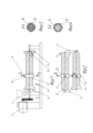
На фиг.1 показана схема измельчителя.Figure 1 shows a diagram of the chopper.
На фиг.2 приведен вид приводных цилиндрических барабанов сверху. На фиг.3 и фиг.4 представлены сечения А-А и Б-Б соответственно Измельчитель содержит устройства загрузки 1 и выгрузки 2, приводные цилиндрические барабаны 3 и 4, на внутренних поверхностях которых размещены спиральные направляющие в виде профилированных полых элементов, перегрузочные приспособления 5 и 6, соединяющие торцевые части барабанов, к торцам барабанов присоединены конические камеры 7 и 8 со спиральными направляющими, выполненные в виде диффузоров и конфузоров соответственно. В центральных частях приводных цилиндрических барабанов 3 и 4 установлены камеры 10 и 11 со сквозными отверстиями 12 прямоугольного сечения, причем отверстия 12 в камере 10 размещены в шахматном порядке, а в камере 11 - по окружности, а на камерах 10 и 11 установлены вибраторы 13. В конических камерах 8, выполненных в виде конфузоров, к спиральным направляющим прикреплены цилиндрические билы 14.Figure 2 shows a top view of the drive cylindrical drums. Figure 3 and Figure 4 show sections A-A and B-B, respectively. The chopper contains loading devices 1 and unloading 2, cylindrical drive drums 3 and 4, on the inner surfaces of which spiral guides in the form of profiled hollow elements are placed, reloading
Измельчитель работает следующим образом.The chopper works as follows.
Подлежащие измельчению материалы поступают из устройства загрузки 1 в коническую камеру 7, где движутся по спиральным направляющим, а затем направляются в приводной цилиндрический барабан 3. При движении по спиральным направляющим происходит измельчение частиц за счет истирания друг о друга и удара при падении в результате движения. Далее предварительно измельченный материал поступает в камеру 10. Здесь частицы попадают в сквозные отверстия 12 прямоугольного сечения, расположенные в шахматном порядке. При движении в сквозных отверстиях 12 материал интенсивно измельчается. Прямоугольное сечение отверстий 12 способствует взаимодействию частиц со стенками и ребрами внутренних поверхностей, многократным столкновениям и ударам, что способствует интенсивному измельчению.The materials to be crushed come from the loading device 1 into the conical chamber 7, where they move along spiral guides, and then are sent to the cylindrical drive drum 3. When moving along the spiral guides, the particles are crushed due to abrasion against each other and impact when falling as a result of the movement. Next, the pre-crushed material enters
Далее материал снова движется по спиральным направляющим барабана 3, поступает в коническую камеру 8, выполненную в виде конфузора, в которой к спиральным направляющим прикреплены цилиндрические билы 14. Здесь измельчение происходит при воздействии на частицы билов 14, которые при вращении барабана 3 взаимодействуют с материалом, измельчая его. Затем материал выгружается через перегрузочное приспособление 5 в коническую камеру 7, присоединенную к приводному цилиндрическому барабану 4. Процесс повторяется. При достижении материалом конической камеры 8, присоединенной к приводному цилиндрическому барабану 4, осуществляется выгрузка измельченного материала в устройство выгрузки 2 через перегрузочное приспособление 6.Next, the material again moves along the spiral guides of the drum 3, enters a
Наличие конических камер 7 и 8 способствует интенсификации измельчения за счет изменения кривизны траекторий движения материала.The presence of
Благодаря тому, что в центральных частях приводных цилиндрических барабанов 3 и 4 установлены камеры 10 и 11 со сквозными отверстиями 12 прямоугольного сечения, причем отверстия 12 в камере 10 размещены в шахматном порядке, а в камере 11 - по окружности, обеспечивается интенсивное измельчение за счет воздействия на частицы переменных нагрузок при движении внутри сквозных отверстий 12, вызывающих истирание частиц, многократные разнонаправленные столкновения различной интенсивности. Различные силовые воздействия на измельчаемый материал в камерах 10 и 11 вызваны разным расположением отверстий 12.Due to the fact that
Кроме того, повышению степени измельчения способствует наличие на камерах 10 и 11 вибраторов 13, заставляющих частицы материалов в камерах 10 и 11 вибрировать и истираться.In addition, the increase in the degree of grinding is facilitated by the presence of
Предлагаемый измельчитель позволяет осуществлять эффективное измельчение материалов без использования мелющих тел.The proposed grinder allows for efficient grinding of materials without the use of grinding media.
Claims (1)
Publications (1)
| Publication Number | Publication Date |
|---|---|
| RU2809999C1 true RU2809999C1 (en) | 2023-12-21 |
Family
ID=
Citations (6)
| Publication number | Priority date | Publication date | Assignee | Title |
|---|---|---|---|---|
| SU1001549A1 (en) * | 1981-07-06 | 1986-08-30 | Государственный Всесоюзный Научно-Исследовательский Институт Цементной Промышленности "Ниицемент" | Interchamber partition of tube mill |
| CN2154745Y (en) * | 1993-04-10 | 1994-02-02 | 许开宏 | Bowl mill |
| RU2021021C1 (en) * | 1990-10-26 | 1994-10-15 | Акционерное общество закрытого типа "Суперкерамика" | Ball mill |
| RU2581489C2 (en) * | 2014-07-11 | 2016-04-20 | Федеральное государственное бюджетное образовательное учреждение высшего профессионального образования "Ярославский государственный технический университет" (ФГБОУВПО "ЯГТУ") | Shredder |
| RU2614796C1 (en) * | 2016-03-21 | 2017-03-29 | Федеральное государственное бюджетное образовательное учреждение высшего профессионального образования "Кубанский государственный аграрный университет" | Vibration grinder |
| CN210131684U (en) * | 2019-04-02 | 2020-03-10 | 曲靖方园环保建材有限公司 | Grinding device for ultrafine fly ash |
Patent Citations (6)
| Publication number | Priority date | Publication date | Assignee | Title |
|---|---|---|---|---|
| SU1001549A1 (en) * | 1981-07-06 | 1986-08-30 | Государственный Всесоюзный Научно-Исследовательский Институт Цементной Промышленности "Ниицемент" | Interchamber partition of tube mill |
| RU2021021C1 (en) * | 1990-10-26 | 1994-10-15 | Акционерное общество закрытого типа "Суперкерамика" | Ball mill |
| CN2154745Y (en) * | 1993-04-10 | 1994-02-02 | 许开宏 | Bowl mill |
| RU2581489C2 (en) * | 2014-07-11 | 2016-04-20 | Федеральное государственное бюджетное образовательное учреждение высшего профессионального образования "Ярославский государственный технический университет" (ФГБОУВПО "ЯГТУ") | Shredder |
| RU2614796C1 (en) * | 2016-03-21 | 2017-03-29 | Федеральное государственное бюджетное образовательное учреждение высшего профессионального образования "Кубанский государственный аграрный университет" | Vibration grinder |
| CN210131684U (en) * | 2019-04-02 | 2020-03-10 | 曲靖方园环保建材有限公司 | Grinding device for ultrafine fly ash |
Similar Documents
| Publication | Publication Date | Title |
|---|---|---|
| RU2373809C1 (en) | Drum food mixer | |
| RU2372818C1 (en) | Loose material mixer | |
| RU2809999C1 (en) | Grinder | |
| RU2362627C1 (en) | Tubular helical mill | |
| RU2372817C1 (en) | Device to mix fodders | |
| RU102540U1 (en) | VERTICAL HAMMER MILL | |
| RU2362629C1 (en) | Conic helical mill | |
| RU2456092C1 (en) | Screen | |
| RU199892U1 (en) | PIPE BALL MILL | |
| RU2362628C1 (en) | Device for grinding of loose materials | |
| RU2633554C1 (en) | Disintegrator | |
| US4917312A (en) | Ball tube mill | |
| RU2568496C1 (en) | Tubular continuous-operation mill | |
| RU2560988C1 (en) | Drum ball crusher | |
| RU2782214C1 (en) | Ball mill | |
| RU2681130C1 (en) | Centrifugal disk grinder | |
| RU2684794C1 (en) | Continuous concrete mixer | |
| RU2821111C1 (en) | Granulator of loose media | |
| RU2542203C1 (en) | Device for finishing and grinding processing | |
| RU2546180C1 (en) | Mixer of loose materials | |
| RU2513074C1 (en) | Concrete mixer | |
| RU2792452C1 (en) | Centrifugal disc grinder | |
| RU2826402C1 (en) | Ball mill | |
| RU2742527C1 (en) | A desintegrator | |
| RU2786114C1 (en) | Centrifugal disc grinder |