RU2789762C1 - Vacuum deaeration assembly - Google Patents
Vacuum deaeration assembly Download PDFInfo
- Publication number
- RU2789762C1 RU2789762C1 RU2022112815A RU2022112815A RU2789762C1 RU 2789762 C1 RU2789762 C1 RU 2789762C1 RU 2022112815 A RU2022112815 A RU 2022112815A RU 2022112815 A RU2022112815 A RU 2022112815A RU 2789762 C1 RU2789762 C1 RU 2789762C1
- Authority
- RU
- Russia
- Prior art keywords
- pipeline
- working water
- water
- working
- pump
- Prior art date
Links
Images
Abstract
Description
Изобретение относится к области подготовки воды для теплоэнергетических установок.The invention relates to the field of water treatment for thermal power plants.
Известен аналог – узел вакуумной деаэрации, содержащий водоструйный эжектор, к которому подключены трубопровод отвода выпара, трубопровод рабочей воды, в который включен насос. Трубопровод рабочей воды подключен к баку рабочей воды. Водоструйный эжектор в данной схеме подключен по замкнутой схеме, так как вода из бака рабочей воды с помощью насоса подается в водоструйный эжектор, а затем поступает обратно в бак рабочей воды. Из бака рабочей воды отработанная в водоструйном эжекторе рабочая вода сбрасывается в канал гидрозолоудаления (см. Шарапов В. И., Орлов М. Е. Технологии обеспечения пиковой нагрузки систем теплоснабжения. - М.: Издательство «Новости теплоснабжения», 2006., рис. 2.16 на с. 87). Этот аналог принят в качестве прототипа.A known analogue is a vacuum deaeration unit containing a water-jet ejector, to which a vapor discharge pipeline is connected, a working water pipeline, which includes a pump. The working water pipeline is connected to the working water tank. The water jet ejector in this scheme is connected in a closed circuit, since water from the working water tank is supplied to the water jet ejector by means of a pump, and then flows back into the working water tank. From the working water tank, the working water used in the water jet ejector is discharged into the hydraulic ash removal channel (see Sharapov V.I., Orlov M.E. Technologies for ensuring the peak load of heat supply systems. - M .: Publishing house "News of heat supply", 2006., fig. 2.16 on p. 87). This analog is taken as a prototype.
Недостаток аналога и прототипа заключается в высокой температуре рабочей воды эжектора по причине её циркуляции по замкнутому контуру, что значительно уменьшает вакуум в вакуумном деаэраторе, а также существенным недостатком является сброс рабочей воды из бака рабочей воды в канал гидрозолоудаления, что ведет к увеличению потерь воды и снижению экономичности работы теплоэнергетической установки.The disadvantage of analogue and prototype is the high temperature of the working water of the ejector due to its circulation in a closed circuit, which significantly reduces the vacuum in the vacuum deaerator, and a significant disadvantage is the discharge of working water from the working water tank into the hydraulic ash removal channel, which leads to an increase in water losses and reducing the efficiency of the heat and power plant.
Задачей изобретения является создание узла вакуумной деаэрации, обеспечивающего наиболее глубокий вакуум в вакуумном деаэраторе, а также снижает потери рабочей воды и увеличивает экономичность теплоэнергетической установки.The objective of the invention is to create a vacuum deaeration unit that provides the deepest vacuum in the vacuum deaerator, and also reduces the loss of working water and increases the efficiency of a thermal power plant.
Технический результат достигается тем, что предложен узел вакуумной деаэрации, содержащий водоструйный эжектор, трубопровод отвода выпара, трубопровод рабочей воды, подключенный к баку рабочей воды, и включенный в трубопровод рабочей воды насос.The technical result is achieved by the fact that a vacuum deaeration unit is proposed, containing a water-jet ejector, a vapor discharge pipeline, a working water pipeline connected to a working water tank, and a pump included in the working water pipeline.
Особенность заключается в том, что трубопровод рабочей воды после насоса подключен к обратному циркуляционному трубопроводу, который в свою очередь подключен к градирне, к которой также подключен подающий циркуляционный трубопровод с включенным в него насосом, к подающему и обратному циркуляционным трубопроводам подключен конденсатор турбины, к подающему циркуляционному трубопроводу дополнительно подключен трубопровод рабочей воды.The peculiarity lies in the fact that the working water pipeline after the pump is connected to the return circulation pipeline, which in turn is connected to the cooling tower, to which the supply circulation pipeline with the pump included in it is also connected, a turbine condenser is connected to the supply and return circulation pipelines, a turbine condenser is connected to the supply the circulation pipeline is additionally connected to the working water pipeline.
Далее рассмотрим сведения, подтверждающие возможность осуществления заявленного изобретения.Next, consider the information confirming the possibility of implementing the claimed invention.
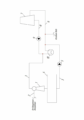
На чертеже изображена схема предлагаемого устройства. Устройство содержит водоструйный эжектор 1, к которому подключены трубопровод 2 отвода выпара и трубопровод 3 рабочей воды, который в свою очередь подключен к баку 4 рабочей воды. В трубопровод 3 рабочей воды включен насос 5, а сам трубопровод 3 подключен к обратному циркуляционному трубопроводу 6. Обратный циркуляционный трубопровод 6 подключен к градирне 7, к которой также подключен подающий циркуляционный трубопровод 8, в который включен насос 9. Также к циркуляционным трубопроводам 6 и 8 подключен конденсатор 10 турбины, а к подающему циркуляционному трубопроводу 8 дополнительно подключен трубопровод 3 рабочей воды.The drawing shows a diagram of the proposed device. The device contains a water-jet ejector 1, which is connected to the pipeline 2 removal of steam and the
Узел вакуумной деаэрации работает следующим образом. The vacuum deaeration unit operates as follows.
Для создания вакуума в вакуумном деаэраторе и удаления выпара, образовавшегося в процессе деаэрации, водоструйный эжектор 1 по трубопроводу 2 отвода выпара откачивает выпар с помощью рабочей воды, циркулируемой по трубопроводу 3 рабочей воды. Нагретая от выпара и отработанная в водоструйном эжекторе 1 рабочая вода поступает в бак 4 рабочей воды, откуда потом с помощью насоса 5 подается в обратный циркуляционный трубопровод 6. В обратный циркуляционный трубопровод 6 также подается исходная химически-очищенная вода. Далее общий поток воды подается в градирню 7, где происходит охлаждение общего потока воды. После градирни 7 часть охлажденной воды по подающему циркуляционному трубопроводу 8 с помощью насоса 9 подается в конденсатор 10 турбины, а другая часть подается в трубопровод 3 рабочей воды.To create a vacuum in the vacuum deaerator and remove the steam generated during the deaeration process, the water jet ejector 1 pumps out the steam through the steam outlet pipeline 2 with the help of working water circulating through the working
Необходимо пояснить, что рабочая вода, проходя через водоструйный эжектор 1, постепенно нагревается за счёт температуры уходящих газов, отсасываемых из вакуумного деаэратора. Соответственно, с увеличением температуры рабочей воды уменьшается вакуум в вакуумном деаэраторе. Для решения подобной проблемы в данной схеме нагретая и отработанная в водоструйном эжекторе 1 рабочая вода охлаждается за счёт подмешивания исходной воды и охлажденного конденсата турбины в обратный циркуляционный трубопровод 6 и далее общий поток воды дополнительно охлаждается в градирне 7, откуда потом подается в трубопровод 3 рабочей воды эжектора и в конденсатор 10 турбины.It should be clarified that the working water, passing through the water jet ejector 1, gradually heats up due to the temperature of the flue gases sucked from the vacuum deaerator. Accordingly, with an increase in the temperature of the working water, the vacuum in the vacuum deaerator decreases. To solve a similar problem in this scheme, the working water heated and exhausted in the water jet ejector 1 is cooled by mixing the source water and the cooled turbine condensate into the
Как правило, в летнее время температура воды после градирни равна температуре наружного воздуха, а в зимнее время года составляет 10-17 °С. Поэтому, согласно данной схеме, температура рабочей воды, поступающей в водоструйный эжектор 1 будет поддерживаться в вышеуказанных пределах.As a rule, in summer the temperature of the water after the cooling tower is equal to the temperature of the outside air, and in the winter it is 10-17 °C. Therefore, according to this scheme, the temperature of the working water entering the water jet ejector 1 will be maintained within the above limits.
Таким образом, заявляемое техническое решение позволяет обеспечить нормальную работу водоструйного эжектора с обеспечением наиболее глубокого вакуума в вакуумном деаэраторе за счет более низкой температуры рабочей воды и повысить экономичность теплоэнергетической установки за счёт участия рабочей воды в цикле работы теплоэнергетической установки.Thus, the proposed technical solution makes it possible to ensure the normal operation of the water jet ejector with the deepest vacuum in the vacuum deaerator due to the lower temperature of the working water and to increase the efficiency of the thermal power plant due to the participation of working water in the operation cycle of the thermal power plant.
Claims (1)
Publications (1)
| Publication Number | Publication Date |
|---|---|
| RU2789762C1 true RU2789762C1 (en) | 2023-02-09 |
Family
ID=
Citations (5)
| Publication number | Priority date | Publication date | Assignee | Title |
|---|---|---|---|---|
| RU2088842C1 (en) * | 1992-02-11 | 1997-08-27 | Ульяновский государственный технический университет | Makeup water treatment plant |
| RU2170705C1 (en) * | 2000-03-17 | 2001-07-20 | Ульяновский государственный технический университет | Makeup water treatment apparatus |
| JP2006346577A (en) * | 2005-06-16 | 2006-12-28 | Miura Co Ltd | High function water generation system |
| CN201306936Y (en) * | 2008-10-16 | 2009-09-09 | 上海青浦工业园区热电有限公司 | Water charging system of condenser in electric power plant |
| CN203906024U (en) * | 2014-04-28 | 2014-10-29 | 河北省电力勘测设计研究院 | Heating device for utilizing dead steam of thermal power plant |
Patent Citations (5)
| Publication number | Priority date | Publication date | Assignee | Title |
|---|---|---|---|---|
| RU2088842C1 (en) * | 1992-02-11 | 1997-08-27 | Ульяновский государственный технический университет | Makeup water treatment plant |
| RU2170705C1 (en) * | 2000-03-17 | 2001-07-20 | Ульяновский государственный технический университет | Makeup water treatment apparatus |
| JP2006346577A (en) * | 2005-06-16 | 2006-12-28 | Miura Co Ltd | High function water generation system |
| CN201306936Y (en) * | 2008-10-16 | 2009-09-09 | 上海青浦工业园区热电有限公司 | Water charging system of condenser in electric power plant |
| CN203906024U (en) * | 2014-04-28 | 2014-10-29 | 河北省电力勘测设计研究院 | Heating device for utilizing dead steam of thermal power plant |
Non-Patent Citations (2)
| Title |
|---|
| В.И. ШАРАПОВ и др. "Технологии обеспечения пиковой нагрузки систем теплоснабжения", Москва "Новости теплоснабжения", 2006, рис.2.16. * |
| О.В. ПАЗУШКИНА и др. "Оценка модернизации включения газоотводящих аппаратов вакуумных деаэраторов", Труды Академэнерго, 2020, N3, с.63-68, рис.2-7. * |
Similar Documents
| Publication | Publication Date | Title |
|---|---|---|
| KR102071105B1 (en) | Gas-steam combined cycle centralized heat supply device and heat supply method | |
| JP5462939B2 (en) | Power generation and seawater desalination complex plant | |
| JP2006070889A (en) | Method and device for power generation and desalination | |
| CN104152608B (en) | Based on the blast furnace slag flushing water generating system of flash evaporation power generation and function of mechanical steam recompression | |
| RU2789762C1 (en) | Vacuum deaeration assembly | |
| CN201680347U (en) | Slot type solar multi-stage thermal utilization device | |
| RU2303145C1 (en) | Thermal power station | |
| CN202883026U (en) | Power station backheating type steam-driven condensate pump system | |
| RU2561780C2 (en) | Combined-cycle plant | |
| RU118360U1 (en) | INSTALLATION OF ELECTRIC-HEAT-WATER SUPPLY OF ENTERPRISES OF MINING, TRANSPORT AND PROCESSING OF HYDROCARBON RAW MATERIALS | |
| RU68599U1 (en) | INSTALLATION FOR DISPOSAL OF HEAT ENERGY | |
| RU2007119765A (en) | HEAT ELECTRIC STATION | |
| RU2580849C1 (en) | Cogeneration turbine | |
| RU51171U1 (en) | HEAT WATER BOILER CIRCUIT | |
| RU2201510C2 (en) | Steam turbine plant | |
| CN210861030U (en) | Heating power device for waste incineration power plant | |
| RU2275515C1 (en) | Thermal power station | |
| RU2143638C1 (en) | Circuit arrangement for steam generators to recover low-potential heat of stack gases | |
| RU2766653C1 (en) | Steam turbine cogeneration plant | |
| RU130670U1 (en) | EVAPORATOR INSTALLATION OF A STEAM-GAS UNIT FOR DISPOSAL TYPE | |
| KR20020068001A (en) | Heat recovery method of additional drain water of feed water heater discharged to condenser in power plant | |
| SU355467A1 (en) | AIR CONDENSATION INSTALLATION | |
| SU659771A1 (en) | Power-and-heating plant | |
| RU2279556C1 (en) | Method of operation of thermal power station | |
| RU2232277C2 (en) | District-heating steam-power plant |