RU2766906C1 - Beverage container system - Google Patents
Beverage container system Download PDFInfo
- Publication number
- RU2766906C1 RU2766906C1 RU2021121014A RU2021121014A RU2766906C1 RU 2766906 C1 RU2766906 C1 RU 2766906C1 RU 2021121014 A RU2021121014 A RU 2021121014A RU 2021121014 A RU2021121014 A RU 2021121014A RU 2766906 C1 RU2766906 C1 RU 2766906C1
- Authority
- RU
- Russia
- Prior art keywords
- closing
- closing element
- manipulation
- axis
- lid
- Prior art date
Links
- 235000013361 beverage Nutrition 0.000 title claims abstract description 45
- 230000035622 drinking Effects 0.000 claims abstract description 124
- 229910052782 aluminium Inorganic materials 0.000 claims description 13
- XAGFODPZIPBFFR-UHFFFAOYSA-N aluminium Chemical compound [Al] XAGFODPZIPBFFR-UHFFFAOYSA-N 0.000 claims description 13
- 239000007788 liquid Substances 0.000 claims description 12
- 239000000463 material Substances 0.000 claims description 11
- 235000014171 carbonated beverage Nutrition 0.000 claims description 9
- 230000006378 damage Effects 0.000 claims description 5
- 239000000853 adhesive Substances 0.000 claims description 4
- 230000001070 adhesive effect Effects 0.000 claims description 4
- 239000013590 bulk material Substances 0.000 claims description 4
- 239000004411 aluminium Substances 0.000 claims description 3
- 239000011344 liquid material Substances 0.000 claims 1
- 230000000694 effects Effects 0.000 abstract description 3
- 239000000126 substance Substances 0.000 abstract 1
- 238000000034 method Methods 0.000 description 14
- 238000009423 ventilation Methods 0.000 description 14
- 230000008569 process Effects 0.000 description 10
- 238000003466 welding Methods 0.000 description 5
- 238000007689 inspection Methods 0.000 description 4
- 238000004026 adhesive bonding Methods 0.000 description 3
- 229910052751 metal Inorganic materials 0.000 description 3
- 239000002184 metal Substances 0.000 description 3
- 238000007789 sealing Methods 0.000 description 3
- 239000005028 tinplate Substances 0.000 description 3
- 235000013405 beer Nutrition 0.000 description 2
- 238000010276 construction Methods 0.000 description 2
- 235000015897 energy drink Nutrition 0.000 description 2
- 238000004519 manufacturing process Methods 0.000 description 2
- 238000012986 modification Methods 0.000 description 2
- 230000004048 modification Effects 0.000 description 2
- 238000004806 packaging method and process Methods 0.000 description 2
- 229920001296 polysiloxane Polymers 0.000 description 2
- 235000014214 soft drink Nutrition 0.000 description 2
- 238000012360 testing method Methods 0.000 description 2
- 230000009471 action Effects 0.000 description 1
- 230000004888 barrier function Effects 0.000 description 1
- 230000009172 bursting Effects 0.000 description 1
- 238000005266 casting Methods 0.000 description 1
- 230000001419 dependent effect Effects 0.000 description 1
- 238000006073 displacement reaction Methods 0.000 description 1
- 238000004049 embossing Methods 0.000 description 1
- 230000005484 gravity Effects 0.000 description 1
- 230000005661 hydrophobic surface Effects 0.000 description 1
- 230000001771 impaired effect Effects 0.000 description 1
- 238000007373 indentation Methods 0.000 description 1
- 238000001746 injection moulding Methods 0.000 description 1
- 238000009434 installation Methods 0.000 description 1
- 239000007769 metal material Substances 0.000 description 1
- 235000019645 odor Nutrition 0.000 description 1
- 238000005457 optimization Methods 0.000 description 1
- 239000004033 plastic Substances 0.000 description 1
- 239000004417 polycarbonate Substances 0.000 description 1
- 229920000515 polycarbonate Polymers 0.000 description 1
- 238000003825 pressing Methods 0.000 description 1
- 238000012545 processing Methods 0.000 description 1
Images


Classifications
-
- B—PERFORMING OPERATIONS; TRANSPORTING
- B65—CONVEYING; PACKING; STORING; HANDLING THIN OR FILAMENTARY MATERIAL
- B65D—CONTAINERS FOR STORAGE OR TRANSPORT OF ARTICLES OR MATERIALS, e.g. BAGS, BARRELS, BOTTLES, BOXES, CANS, CARTONS, CRATES, DRUMS, JARS, TANKS, HOPPERS, FORWARDING CONTAINERS; ACCESSORIES, CLOSURES, OR FITTINGS THEREFOR; PACKAGING ELEMENTS; PACKAGES
- B65D17/00—Rigid or semi-rigid containers specially constructed to be opened by cutting or piercing, or by tearing of frangible members or portions
- B65D17/50—Non-integral frangible members applied to, or inserted in, preformed openings, e.g. tearable strips or plastic plugs
- B65D17/506—Rigid or semi-rigid members, e.g. plugs
-
- B—PERFORMING OPERATIONS; TRANSPORTING
- B65—CONVEYING; PACKING; STORING; HANDLING THIN OR FILAMENTARY MATERIAL
- B65D—CONTAINERS FOR STORAGE OR TRANSPORT OF ARTICLES OR MATERIALS, e.g. BAGS, BARRELS, BOTTLES, BOXES, CANS, CARTONS, CRATES, DRUMS, JARS, TANKS, HOPPERS, FORWARDING CONTAINERS; ACCESSORIES, CLOSURES, OR FITTINGS THEREFOR; PACKAGING ELEMENTS; PACKAGES
- B65D47/00—Closures with filling and discharging, or with discharging, devices
- B65D47/04—Closures with discharging devices other than pumps
- B65D47/20—Closures with discharging devices other than pumps comprising hand-operated members for controlling discharge
- B65D47/26—Closures with discharging devices other than pumps comprising hand-operated members for controlling discharge with slide valves, i.e. valves that open and close a passageway by sliding over a port, e.g. formed with slidable spouts
- B65D47/28—Closures with discharging devices other than pumps comprising hand-operated members for controlling discharge with slide valves, i.e. valves that open and close a passageway by sliding over a port, e.g. formed with slidable spouts having linear movement
- B65D47/286—Closures with discharging devices other than pumps comprising hand-operated members for controlling discharge with slide valves, i.e. valves that open and close a passageway by sliding over a port, e.g. formed with slidable spouts having linear movement between planar parts
-
- B—PERFORMING OPERATIONS; TRANSPORTING
- B65—CONVEYING; PACKING; STORING; HANDLING THIN OR FILAMENTARY MATERIAL
- B65D—CONTAINERS FOR STORAGE OR TRANSPORT OF ARTICLES OR MATERIALS, e.g. BAGS, BARRELS, BOTTLES, BOXES, CANS, CARTONS, CRATES, DRUMS, JARS, TANKS, HOPPERS, FORWARDING CONTAINERS; ACCESSORIES, CLOSURES, OR FITTINGS THEREFOR; PACKAGING ELEMENTS; PACKAGES
- B65D2205/00—Venting means
- B65D2205/02—Venting holes
-
- B—PERFORMING OPERATIONS; TRANSPORTING
- B65—CONVEYING; PACKING; STORING; HANDLING THIN OR FILAMENTARY MATERIAL
- B65D—CONTAINERS FOR STORAGE OR TRANSPORT OF ARTICLES OR MATERIALS, e.g. BAGS, BARRELS, BOTTLES, BOXES, CANS, CARTONS, CRATES, DRUMS, JARS, TANKS, HOPPERS, FORWARDING CONTAINERS; ACCESSORIES, CLOSURES, OR FITTINGS THEREFOR; PACKAGING ELEMENTS; PACKAGES
- B65D2401/00—Tamper-indicating means
- B65D2401/15—Tearable part of the closure
-
- B—PERFORMING OPERATIONS; TRANSPORTING
- B65—CONVEYING; PACKING; STORING; HANDLING THIN OR FILAMENTARY MATERIAL
- B65D—CONTAINERS FOR STORAGE OR TRANSPORT OF ARTICLES OR MATERIALS, e.g. BAGS, BARRELS, BOTTLES, BOXES, CANS, CARTONS, CRATES, DRUMS, JARS, TANKS, HOPPERS, FORWARDING CONTAINERS; ACCESSORIES, CLOSURES, OR FITTINGS THEREFOR; PACKAGING ELEMENTS; PACKAGES
- B65D2517/00—Containers specially constructed to be opened by cutting, piercing or tearing of wall portions, e.g. preserving cans or tins
- B65D2517/0001—Details
- B65D2517/0031—Reclosable openings
- B65D2517/0046—Unusual reclosable openings
-
- B—PERFORMING OPERATIONS; TRANSPORTING
- B65—CONVEYING; PACKING; STORING; HANDLING THIN OR FILAMENTARY MATERIAL
- B65D—CONTAINERS FOR STORAGE OR TRANSPORT OF ARTICLES OR MATERIALS, e.g. BAGS, BARRELS, BOTTLES, BOXES, CANS, CARTONS, CRATES, DRUMS, JARS, TANKS, HOPPERS, FORWARDING CONTAINERS; ACCESSORIES, CLOSURES, OR FITTINGS THEREFOR; PACKAGING ELEMENTS; PACKAGES
- B65D2517/00—Containers specially constructed to be opened by cutting, piercing or tearing of wall portions, e.g. preserving cans or tins
- B65D2517/0001—Details
- B65D2517/0091—Means for venting upon initial opening
-
- Y—GENERAL TAGGING OF NEW TECHNOLOGICAL DEVELOPMENTS; GENERAL TAGGING OF CROSS-SECTIONAL TECHNOLOGIES SPANNING OVER SEVERAL SECTIONS OF THE IPC; TECHNICAL SUBJECTS COVERED BY FORMER USPC CROSS-REFERENCE ART COLLECTIONS [XRACs] AND DIGESTS
- Y02—TECHNOLOGIES OR APPLICATIONS FOR MITIGATION OR ADAPTATION AGAINST CLIMATE CHANGE
- Y02W—CLIMATE CHANGE MITIGATION TECHNOLOGIES RELATED TO WASTEWATER TREATMENT OR WASTE MANAGEMENT
- Y02W30/00—Technologies for solid waste management
- Y02W30/50—Reuse, recycling or recovery technologies
- Y02W30/80—Packaging reuse or recycling, e.g. of multilayer packaging
Abstract
Description
Настоящее изобретение касается системы укупорки емкостей для напитков, в частности банок для напитков. При этом предлагаемая изобретением система укупорки обеспечивает возможность открывания и повторного закрывания емкости для напитков.The present invention relates to a closure system for beverage containers, in particular beverage cans. At the same time, the closure system according to the invention makes it possible to open and re-close the beverage container.
Банки для напитков являются одной из важнейших торговых упаковок для напитков. Они применяются, прежде всего, для газированных напитков, в частности для пива, лимонадов и энергетических напитков, и, как правило, обладают устойчивостью к внутреннему давлению по меньшей мере 6,2 бар. Применяемые сегодня банки для напитков состоят чаще всего из неразъемной, по существу цилиндрической емкости из алюминия или белой жести и, как правило, соединенной в фальц, крышки из алюминия. Для облегчения открывания крышка имеет чаще всего овальную линию надреза, а также приклепанную металлическую лапку, которая при приподнятии вдавливает надрезанный овал под действием рычага внутрь банки и так создает питьевое отверстие. Эта встроенная «открывашка» банки называется также «Stay-on-Tab» (англ. «остающееся ушко»).Beverage cans are one of the most important commercial packaging for drinks. They are used primarily for carbonated drinks, in particular for beer, soft drinks and energy drinks, and generally have an internal pressure resistance of at least 6.2 bar. Beverage cans used today usually consist of a one-piece, essentially cylindrical container made of aluminum or tinplate and, as a rule, a lid made of aluminum that is joined in a fold. To facilitate opening, the lid most often has an oval notch line, as well as a riveted metal tab, which, when lifted, presses the notched oval into the can under the action of a lever and thus creates a drinking hole. This built-in can opener is also called a "Stay-on-Tab".
Преимущества банок для напитков для потребителя заключаются, прежде всего, в их низком собственном весе, в их неразбиваемости и в возможности использовать их после открывания непосредственно в качестве сосуда для питья. Для изготовителей напитков к этому добавляется высокое барьерное действие, так как нейтральность этого материала для запахов и одновременное защищающее от света действие обеспечивают возможность хорошей защиты даже для чувствительных продуктов и долгий срок хранения.The advantages of beverage cans for the consumer lie primarily in their low dead weight, their indestructibility and the possibility of using them directly as a drinking vessel after opening. For beverage manufacturers, a high barrier effect is added to this, since the neutrality of this material for odors and the simultaneous light-protection effect ensure good protection even for sensitive products and a long shelf life.
Основным недостатком банок для напитков «Stay-on-Tab» является отсутствующая до сих пор возможность повторного закрывания. Поэтому было бы предпочтительно предоставить систему укупорки, посредством которой преимущества известных банок для напитков могут комбинироваться с возможностью повторного закрывания.The main disadvantage of "Stay-on-Tab" beverage cans is the lack of reclosability so far. Therefore, it would be preferable to provide a closure system whereby the advantages of known beverage cans can be combined with the possibility of reclosing.
В DE 10 2012 213 093 A1 представлена повторно закрываемая система укупорки. Недостаток, в частности по сравнению с обычными укупорками «Stay-on-Tab», заключается в том, что, во-первых, конструктивные издержки значительно выше. Во-вторых, оснащенная такой системой укупорки крышка гораздо глубже, так что больше не обеспечена возможность укладки крышек в стопу, и необходимы специальные машины для соединения крышек с цилиндрической частью банки.DE 10 2012 213 093 A1 presents a reclosable closure system. The disadvantage, in particular compared to conventional "Stay-on-Tab" closures, is that, firstly, the construction costs are significantly higher. Secondly, the lid provided with such a closure system is much deeper, so that stacking of closures is no longer possible, and special machines are needed to connect the closures to the cylindrical part of the can.
Поэтому задачей изобретения является предоставление улучшенной системы укупорки емкостей для жидкостей или сыпучего материала, в частности банок для напитков или картонных коробок, в частности, при которой емкость, или, соответственно, банка, может повторно закрываться простым образом.It is therefore an object of the invention to provide an improved closure system for containers for liquids or bulk material, in particular beverage cans or cartons, in particular, in which the container, or can, can be reclosed in a simple manner.
Другой задачей является предоставление такой системы укупорки, имеющей гарантийную печать, которая просто, в частности визуально, позволяет отличать неоткрытые емкости от повторно закрытых.Another object is to provide such a sealing system, bearing a guarantee seal, which simply, in particular visually, makes it possible to distinguish between unopened and re-closed containers.
Другой задачей является предоставление такой системы укупорки, которая является особенно компактной, в частности не увеличивает наружные размеры емкости и не ухудшает возможность укладки емкости в стопу.Another object is to provide such a closure system which is particularly compact, in particular does not increase the outer dimensions of the container and does not impair the stackability of the container.
Другой задачей является предоставление такой системы укупорки, которая может изготавливаться при низких конструктивных издержках.Another object is to provide such a closure system which can be manufactured at low construction cost.
Другой задачей является предоставление такой системы укупорки, которая рассчитана на давление по меньшей мере 6,2 бар.Another object is to provide such a closure system which is designed for a pressure of at least 6.2 bar.
Другой задачей является предоставление баночной крышки для банки для напитков, имеющей такую систему укупорки, и банку для напитков, имеющую такую систему укупорки.Another object is to provide a can lid for a beverage can having such a closure system and a beverage can having such a closure system.
Другой задачей является предоставление такой баночной крышки, имеющей такую систему укупорки, причем эта баночная крышка может соединяться с остальным корпусом банки с получением банки для напитков с помощью существующих машин и способов.It is another object to provide such a can lid having such a closure system, where the can lid can be connected to the rest of the can body to form a beverage can using existing machines and methods.
Другой задачей является предоставление такой баночной крышки и такой банки для напитков, которые могут укладываться в стопу, в частности при этом система укупорки является столь плоской, что наружные размеры баночной крышки или, соответственно, банки для напитков не увеличиваются, или их возможность укладки в стопу негативным образом не ухудшается.Another object is to provide a can lid and a beverage can that can be stacked, in particular the closure system is so flat that the external dimensions of the can lid or the beverage can do not increase or are stackable. does not worsen in a negative way.
По меньшей мере одна из этих задач решается путем осуществления отличительных признаков независимых пунктов формулы изобретения. Признаки, которые совершенствуют изобретение альтернативным или предпочтительно образом, содержатся в зависимых пунктах формулы изобретения.At least one of these problems is solved by implementing the features of the independent claims. Features which improve the invention in an alternative or advantageous manner are contained in the dependent claims.
Первый аспект настоящего изобретения касается системы укупорки емкости для напитков, например, банки для напитков. Эта система укупорки имеет закрывающий элемент для закрывания питьевого отверстия крышки емкости для напитков и манипуляционный элемент для открывания питьевого отверстия вручную пользователем. При этом закрывающий элемент может размещаться на нижней стороне крышки и может неподвижно соединяться с манипуляционным элементом на верхней стороне крышки. Закрывающий элемент для закрывания питьевого отверстия выполнен для того, чтобы в закрытом положении накрывать питьевое отверстие по всей площади. Манипуляционный элемент и закрывающий элемент могут располагаться с возможностью движения вдоль первой оси, которая проходит по существу параллельно верхней стороне крышки. При этом движение манипуляционного элемента в первом направлении вдоль первой оси может вызывать движение закрывающего элемента из закрытого положения и открывание питьевого отверстия, а движение манипуляционного элемента в противоположном первому направлению втором направлении вдоль первой оси может вызывать движение закрывающего элемента в закрытое положение и повторное закрывание питьевого отверстия.A first aspect of the present invention relates to a closure system for a beverage container, such as a beverage can. This closure system has a closing element for closing the drinking opening of the beverage container lid and a handling element for opening the drinking opening manually by the user. In this case, the closing element can be placed on the lower side of the lid and can be fixedly connected to the handling element on the upper side of the lid. The closing element for closing the drinking hole is designed to cover the entire area of the drinking hole in the closed position. The handling element and the closure element can be movably positioned along a first axis that extends substantially parallel to the top side of the lid. In this case, the movement of the manipulation element in the first direction along the first axis can cause the movement of the closing element from the closed position and the opening of the drinking hole, and the movement of the manipulation element in the opposite direction to the first direction in the second direction along the first axis can cause the movement of the closing element to the closed position and re-closing the drinking hole .
В собранном состоянии крышка также относится к закрывающему элементу. В этом варианте осуществления закрывающий элемент имеет упомянутую крышку, имеющую верхнюю сторону, нижнюю сторону и питьевое отверстие, кроме того, закрывающий элемент для закрывания питьевого отверстия и манипуляционный элемент для открывания питьевого отверстия вручную пользователем. Тогда в соответствии с изобретением закрывающий элемент размещен на нижней стороне крышки и неподвижно соединен с манипуляционным элементом на верхней стороне крышки. Закрывающий элемент для закрывания питьевого отверстия выполнен для того, чтобы в закрытом положении накрывать питьевое отверстие по всей площади, и манипуляционный элемент и закрывающий элемент расположены с возможностью движения вдоль первой оси, которая проходит по существу параллельно верхней стороне крышки. При этом движение манипуляционного элемента в первом направлении вдоль первой оси вызывает движение закрывающего элемента из закрытого положения и открывание питьевого отверстия, а движение манипуляционного элемента в противоположном первому направлению втором направлении вдоль первой оси (обратное) движение закрывающего элемента в закрытое положение и вместе с тем повторное закрывание питьевого отверстия.In the assembled state, the cover also refers to the closing element. In this embodiment, the closure element has said lid having a top side, a bottom side and a drinking hole, in addition, a closure element for closing the drinking hole and a handling element for opening the drinking hole manually by the user. Then, according to the invention, the closing element is placed on the lower side of the lid and is fixedly connected to the handling element on the upper side of the lid. The closing element for closing the drinking hole is designed to cover the entire area of the drinking hole in the closed position, and the manipulation element and the closing element are movable along the first axis, which runs essentially parallel to the upper side of the cover. In this case, the movement of the manipulation element in the first direction along the first axis causes the movement of the closing element from the closed position and the opening of the drinking hole, and the movement of the manipulation element in the opposite direction to the first direction in the second direction along the first axis (reverse) movement of the closing element to the closed position and, at the same time, repeated closing the drinking hole.
По одному из вариантов осуществления система укупорки имеет по меньшей мере один предохранительный и/или контрольный элемент, причем этот контрольный элемент выполнен таким образом, что онAccording to one of the embodiments, the closure system has at least one safety and/or control element, and this control element is designed in such a way that it
- имеет первое состояние, пока манипуляционный элемент не движется, и/или закрывающий элемент не движется из закрытого положения, и- has the first state until the manipulation element moves and/or the closing element moves from the closed position, and
- принимает по меньшей мере визуально отличающееся от первого состояния второе состояние, как только манипуляционный элемент движется в первом направлении, или, соответственно, закрывающий элемент движется из закрытого положения.- assumes a second state at least visually different from the first state, as soon as the manipulation element moves in the first direction, or, accordingly, the closing element moves from the closed position.
Такой предохранительный элемент, который не обязательно должен предоставлять функцию контроля, предохраняет манипуляционный элемент предпочтительно от смещения.Such a safety element, which does not necessarily have to provide a control function, preferably prevents the manipulation element from being dislodged.
При варианте осуществления в виде контрольного элемента второе состояние может приниматься необратимо. Контрольный элемент сохраняет это второе состояние, в частности, даже тогда, когда манипуляционный элемент движется обратно во втором направлении, или, соответственно, когда закрывающий элемент движется обратно в закрытое положение.In the control element embodiment, the second state may be accepted irreversibly. The control element retains this second state, in particular even when the handling element moves back in the second direction, or, respectively, when the closing element moves back to the closed position.
Такой контрольный элемент позволяет пользователю различать, является ли емкость для напитков еще не открытой, или была ли система укупорки уже использована для открывания и повторного закрывания емкости.Such a control element allows the user to distinguish whether the beverage container is not yet open, or whether the closure system has already been used to open and re-close the container.
В одном из вариантов осуществления контрольный элемент имеет по меньшей мере одну, расположенную видимым (т.е. пользователю) снаружи образом, контрольную перемычку, причем эта контрольная перемычка расположена и устроена так, что она разрушается, когда манипуляционный элемент движется в первом направлении, или, соответственно, когда закрывающий элемент движется из закрытого положения. При этом указанная или указанные контрольные перемычки могут иметь каждая место предполагаемого разрушения.In one embodiment, the control element has at least one externally visible (i.e., user-friendly) control bridge, the control bridge being positioned and configured to collapse when the manipulation element is moved in a first direction, or , respectively, when the closing element moves from the closed position. In this case, the specified or specified control jumpers can each have a place of the alleged destruction.
В другом варианте осуществления контрольный элемент расположен и устроен таким образом, что движение манипуляционного элемента в первом направлении вызывает движение отклонения контрольного элемента, посредством которого осуществляется разрушение указанной по меньшей мере одной контрольной перемычки.In another embodiment, the control element is located and arranged in such a way that the movement of the manipulation element in the first direction causes the movement of the deviation of the control element, through which the destruction of the specified at least one control jumper.
В другом варианте осуществления контрольный элемент установлен на манипуляционном элементе посредством одной или нескольких поперечных перемычек (например, посредством по меньшей мере двух поперечных перемычек). Они обеспечивают предпочтительно возможность движения контрольного элемента вокруг оси наклона, ортогональной первой оси. При этом указанная по меньшей мере одна контрольная перемычка проходит предпочтительно вдоль первой оси и может быть, в частности, закреплена как на контрольном элементе, так и на манипуляционном элементе. Кроме того, контрольный элемент расположен на манипуляционном элементе таким образом, что он сталкивается с крышкой, когда манипуляционный элемент движется в первом направлении, при этом движение отклонения полностью или частично вызывается этим столкновением, и при этом движение отклонения включает в себя наклон контрольного элемента вокруг оси наклона.In another embodiment, the control element is mounted on the handling element via one or more transverse bridges (for example, via at least two transverse bridges). They preferably make it possible for the control element to move about an inclination axis orthogonal to the first axis. In this case, said at least one control bridge preferably extends along the first axis and can, in particular, be attached both to the control element and to the manipulation element. In addition, the control element is located on the manipulation element in such a way that it collides with the lid when the manipulation element moves in the first direction, while the deflection movement is completely or partially caused by this collision, and the deflection movement includes tilting the control element around the axis tilt.
Соответственно в этом специальном варианте осуществления контрольные перемычки разрушаются вследствие движения наклона вокруг оси, ортогональной ориентации контрольных перемычек.Accordingly, in this special embodiment, the control webs are destroyed due to tilt movement about an axis orthogonal to the orientation of the control webs.
Вместо одной или нескольких поперечных перемычек предохранительный и/или контрольный элемент может быть соединен с манипуляционным элементом также посредством шарнира. Этот шарнир может быть создан засечкой в манипуляционном элементе. Шарнир задает предпочтительно ось наклона, которая ортогональна первой оси.Instead of one or more transverse bridges, the safety and/or control element can also be connected to the manipulation element by means of a hinge. This hinge can be created by a notch in the manipulation element. The hinge preferably defines an inclination axis which is orthogonal to the first axis.
Предохранительный и/или контрольный элемент может иметь одну или несколько контрольных перемычек, которые соединяют предохранительный и/или контрольный элемент манипуляционного элемента с ручкой и предусмотрены для того, чтобы при приподнятии ручки разрушаться и так делать приподнятие ручки необратимо видимым.The safety and/or control element can have one or more control bridges, which connect the safety and/or control element of the handling element to the handle and are provided in order to be destroyed when the handle is lifted and thus make the lifting of the handle irreversibly visible.
В другом варианте осуществления контрольный элемент на своей нижней стороне имеет возвышение, которое расположено таким образом, что при движении манипуляционного элемента в первом направлении оно сталкивается с крышкой. Это возвышение может быть выполнено в виде крючка.In another embodiment, the control element has an elevation on its lower side, which is arranged in such a way that when the manipulation element moves in the first direction, it collides with the lid. This elevation can be made in the form of a hook.
В частности, при этом движение отклонения по меньшей мере частично вызывается этим столкновением. Возвышение может прилегать к крышке, например, на крае питьевого отверстия или на конце направляющей прорези питьевого отверстия. Кроме того, закрывающий элемент может иметь углубление, при этом возвышение вдается в это углубление.In particular, the deflection movement is at least partially caused by this collision. The elevation may rest against the lid, for example at the edge of the drinking hole or at the end of the guide slot of the drinking hole. In addition, the closure element may have a recess, with the elevation protruding into this recess.
В другом варианте осуществления манипуляционный элемент выполнен цельно с контрольным элементом. Это означает, в частности, что контрольный элемент выполнен в виде интегральной составной части манипуляционного элемента и состоит из того же самого материала. Например, манипуляционный элемент и контрольный элемент могут состоять из алюминия.In another embodiment, the manipulation element is integral with the control element. This means in particular that the control element is designed as an integral part of the manipulation element and consists of the same material. For example, the manipulation element and the control element may be made of aluminum.
В другом варианте осуществления контрольный элемент предусмотрен на закрывающем элементе. В первом состоянии он вставляется в отверстие крышки и тогда виден снаружи через смотровое отверстие манипуляционного элемента. В частности, контрольный элемент может быть устроен и размещен относительно отверстия крышки таким образом, что он разрушается, когда манипуляционный элемент движется в первом направлении, или, соответственно, когда закрывающий элемент движется из закрытого положения.In another embodiment, the control element is provided on the closing element. In the first state, it is inserted into the opening of the lid and is then visible from the outside through the viewing hole of the manipulation element. In particular, the control element can be arranged and positioned relative to the opening of the cover in such a way that it is destroyed when the handling element is moved in the first direction, or, respectively, when the closing element is moved from the closed position.
По другому варианту осуществления системы укупорки питьевое отверстие имеет направляющую прорезь, которая проходит вдоль первой оси, а манипуляционный элемент и/или закрывающий элемент имеют направляющий элемент, который вставляется в направляющую прорезь, так что манипуляционный элемент может двигаться исключительно вдоль первой оси. Кроме того, этот направляющий элемент может служить, например, для того, чтобы неподвижно соединять друг с другом манипуляционный элемент и закрывающий элемент. Направляющая прорезь и питьевое отверстие могут переходить друг в друга и/или быть выполнены в виде одного сплошного общего отверстия. Направляющая прорезь является опциональной.According to another embodiment of the closure system, the drinking opening has a guide slot that extends along the first axis, and the handling element and/or the closure element have a guide element that is inserted into the guide slot, so that the manipulation element can move exclusively along the first axis. In addition, this guide element can serve, for example, to permanently connect the handling element and the closure element to each other. The guide slot and the drinking hole can pass into each other and/or be made in the form of one continuous common hole. The guide slot is optional.
Питьевое отверстие, за исключением направляющей прорези, выполнено предпочтительно округлым, овальным или в форме полумесяца.The drinking opening, with the exception of the guide slot, is preferably round, oval or crescent shaped.
По другому варианту осуществления системы укупорки закрывающий элемент имеет по меньшей мере одну насечку, которая расположена таким образом, что при движении закрывающего элемента из закрытого положения открывание питьевого отверстия осуществляется в первую очередь через эту насечку. Для этого насечка может быть расположена, например, рядом с краевым участком питьевого отверстия, в частности краевым участком питьевого отверстия, которые при движении закрывающего элемента освобождается в первую очередь. Насечка может быть расположена на закрывающем элементе таким образом, чтобы она была размещена на первой оси, когда закрывающий элемент находится в закрытом положении.According to another embodiment of the closure system, the closure element has at least one notch, which is located in such a way that when the closure element moves from the closed position, the opening of the drinking opening is carried out primarily through this notch. To this end, the incision can be located, for example, next to the edge region of the drinking opening, in particular the edge region of the drinking opening, which is released first when the closure element is moved. The notch may be positioned on the closure element such that it is placed on the first axis when the closure element is in the closed position.
По другому варианту осуществления системы укупорки крышка имеет на первой оси насечку или отверстие, а закрывающий элемент выполнен для того, чтобы в закрытом положении накрывать, кроме питьевого отверстия, также эту насечку или, соответственно, отверстие. При этом насечка возле питьевого отверстия или, соответственно, отверстие расположены рядом с питьевым отверстием соответственно таким образом, что при движении закрывающего элемента из закрытого положения насечка или, соответственно, отверстие соответственно открывается раньше питьевого отверстия. Для этого насечка или отверстие может быть расположено, например, рядом с краевым участком питьевого отверстия, в частности краевым участком питьевого отверстия, который при движении закрывающего элемента из закрытого положения в открытое положение освобождается в первую очередь.According to another embodiment of the closure system, the lid has a notch or hole on the first axis, and the closing element is designed to cover, in addition to the drinking hole, also this notch or hole in the closed position. In this case, the notch near the drinking hole or, respectively, the hole is located next to the drinking hole, respectively, in such a way that when the closing element moves from the closed position, the notch or, respectively, the hole, respectively, opens before the drinking hole. To this end, the notch or opening can be located, for example, next to the edge portion of the drinking hole, in particular the edge portion of the drinking hole, which is released first when the closure element moves from the closed position to the open position.
По одному из вариантов осуществления крышка имеет по меньшей мере одно углубление, которое расположено относительно закрытого положения закрывающего элемента таким образом, что вследствие движения закрывающего элемента из закрытого положения, т.е., в частности, движения в первом направлении, указанное по меньшей мере одно углубление полностью или частично накрывается закрывающим элементом. При этом указанное по меньшей мере одно углубление может быть вычеканено или выштамповано либо в верхней стороне, либо в нижней стороне крышки.According to one of the embodiments, the lid has at least one recess, which is located relative to the closed position of the closing element in such a way that due to the movement of the closing element from the closed position, i.e., in particular, movement in the first direction, the specified at least one the recess is completely or partially covered by a closing element. At the same time, said at least one recess can be embossed or stamped either in the upper side or in the lower side of the lid.
В одном их вариантов осуществления упомянутое по меньшей мере одно углубление расположено таким образом, а закрывающий элемент выполнен с такими размерами, что при движении закрывающего элемента из закрытого положения указанное по меньшей мере одно углубление до открывания питьевого отверстия по меньшей мере частично покрывается закрывающим элементом, и благодаря этому становится возможен газообмен, т.е. между нижней и верхней стороной крышки или, соответственно, внутренним пространством банки и окружающей средой, когда указанное по меньшей мере одно углубление частично накрыто закрывающим элементом, в частности когда одновременно питьевое отверстие (включая направляющую прорезь, если она имеется) по меньшей мере частично покрыто закрывающим элементом. Этот газообмен служит, в частности, для выравнивания избыточного давления и/или недостаточного давления в емкости для напитков.In one of the embodiments, said at least one recess is located in such a way, and the closing element is sized such that when the closing element moves from the closed position, said at least one recess is at least partially covered by the closing element before opening the drinking hole, and due to this, gas exchange becomes possible, i.e. between the lower and upper side of the lid or, respectively, the interior of the jar and the environment, when said at least one recess is partially covered by the closure element, in particular when at the same time the drinking opening (including the guide slot, if any) is at least partially covered by the closure element. This gas exchange serves in particular to equalize overpressure and/or underpressure in the beverage container.
В одном и вариантов осуществления указанное по меньшей мере одно углубление расположено в нижней стороне крышки, и газообмен осуществляется через указанное по меньшей мере одно углубление. Углубления могут изготавливаться (например, чеканиться или штамповаться), в частности, таким образом, чтобы каждому углублению соответствовало возвышение на верхней стороне крышки.In one embodiment, said at least one recess is located in the underside of the lid, and gas exchange takes place through said at least one recess. The recesses can be produced (for example minted or stamped) in particular in such a way that each recess corresponds to an elevation on the top side of the lid.
В другом варианте осуществления указанное по меньшей мере одно углубление расположено в верхней стороне крышки так, что на нижней стороне крышки существует соответствующее углублению возвышение, при этом закрывающий элемент при накрывании указанного по меньшей мере одного углубления дистанцируется этим возвышением от нижней стороны крышки, и газообмен осуществляется, минуя указанное по меньшей мере одно возвышение, например, в промежуточном пространстве между двумя возвышениями.In another embodiment, said at least one recess is located in the upper side of the lid so that on the lower side of the lid there is an elevation corresponding to the recess, while the closing element, when closing the specified at least one recess, is distanced by this elevation from the lower side of the lid, and gas exchange is carried out , bypassing the specified at least one elevation, for example, in the intermediate space between two elevations.
По другому варианту осуществления неподвижное соединение закрывающего элемента и манипуляционного элемента осуществляется посредством либо сварного соединения, клеевого соединения, клепаного соединения, либо стопорного соединения. Предпочтительно между закрывающим элементом и манипуляционным элементом предусмотрена только одна единственная сварка (в частности, одна единственная ультразвуковая или фрикционная сварка) или только одна единственная заклепка. В частности, предпочтительно предусмотрена только одна единственная сварка (в частности, одна единственная ультразвуковая сварка) в области соединения между крепежным штифтом закрывающего элемента и вырезом манипуляционного элемента.According to another embodiment, the fixed connection of the closure element and the manipulation element is by means of either a welded connection, an adhesive connection, a riveted connection, or a retaining connection. Preferably, between the closing element and the manipulation element, only one single welding (in particular one single ultrasonic or friction welding) or only one single rivet is provided. In particular, only one single weld (in particular one single ultrasonic weld) is preferably provided in the region of the connection between the fastening pin of the closure element and the opening of the handling element.
Такое неподвижное соединение предпочтительно является не варьируемым по своей длине и/или фиксированным от вращения. Другими словами, расстояние между манипуляционным элементом и закрывающим элементом в области этого соединения предпочтительно является постоянным и/или не варьируемым и/или эти два элемента не могут вращаться друг относительно друга.Such a fixed connection is preferably non-variable in its length and/or fixed against rotation. In other words, the distance between the handling element and the closing element in the area of this connection is preferably constant and/or not variable and/or the two elements cannot rotate relative to each other.
В одном из вариантов осуществления закрывающего элемента закрывающий элемент имеет крепежный штифт, а манипуляционный элемент имеет вырез, причем этот крепежный штифт для неподвижного соединения закрывающего элемента и манипуляционного элемента введен в этот вырез. В частности, крепежный штифт может иметь крючок с зазубриной для застопоривания на манипуляционном элементе, и/или вставляться в направляющую прорезь питьевого отверстия, которая проходит вдоль первой оси.In one of the embodiments of the closure element, the closure element has a fastening pin, and the manipulation element has a cutout, this fastening pin for a fixed connection of the closing element and the manipulation element being inserted into this cutout. In particular, the fixing pin may have a barbed hook for locking onto the handling element and/or be inserted into a guide slot of the drinking hole which extends along the first axis.
По другому варианту осуществления закрывающего элемента манипуляционный элемент имеет прилегающую к баночной крышке ручку, причем эта ручка на нижней стороне предпочтительно выполнена с фаской, и может ставиться стоймя посредством движения поворота вокруг оси поворота, ортогональной первой оси, по меньшей мере на 45°, в частности по меньшей мере 90°. В частности, при этомAccording to another embodiment of the closure element, the handling element has a handle adjacent to the jar lid, this handle being preferably chamfered on the underside and can be placed upright by means of a pivoting movement about a pivot axis orthogonal to the first axis by at least 45°, in particular at least 90°. In particular, while
- движение поворота может осуществляться в направлении второго направления, то есть против направления открывания,- the pivoting movement can be carried out in the direction of the second direction, i.e. against the opening direction,
- манипуляционный элемент может быть выполнен цельно с ручкой, при этом манипуляционный элемент имеет действующую в качестве шарнира засечку в верхней стороне, которая проходит вдоль оси поворота, или- the handling element can be made in one piece with a handle, whereby the handling element has a notch acting as a hinge in the upper side, which extends along the axis of rotation, or
- ручка может быть выполнена в форме полукольца, при этом ручка может быть расположена, например, вокруг контрольного элемента.- the handle can be made in the form of a semicircle, while the handle can be located, for example, around the control element.
По другому варианту осуществления системы укупорки как крышка, так и манипуляционный элемент состоят из алюминия, кроме того, также закрывающий элемент может состоять из алюминия.According to another embodiment of the closure system, both the lid and the handling element are made of aluminum, in addition, the closure element can also be made of aluminum.
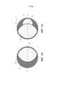
По другому варианту осуществления системы укупорки закрывающий элемент по своей внешней форме адаптирован к форме крышки. В частности, закрывающий элемент может быть овальным или эллиптическим и иметь вдоль второй оси, ортогональной первой оси, большую длину, чем вдоль первой оси.According to another embodiment of the closure system, the closure element is adapted in its external shape to the shape of the lid. In particular, the closure element may be oval or elliptical and have a longer length along a second axis, orthogonal to the first axis, than along the first axis.
Второй аспект изобретения касается емкости для напитков, имеющей систему укупорки по первому аспекту изобретения. В частности, эта емкость для напитков представляет собой банку для напитков, имеющую по существу цилиндрический корпус для помещения жидкостей, в частности газированных напитков. При этом банка может быть изготовлена, в частности, из белой жести или алюминия. Крышка системы укупорки может быть закреплена на банке посредством соединения в фальц.A second aspect of the invention relates to a beverage container having a closure system according to the first aspect of the invention. In particular, this beverage container is a beverage can having a substantially cylindrical housing for containing liquids, in particular carbonated beverages. In this case, the can can be made, in particular, from tinplate or aluminium. The lid of the capping system can be secured to the can by means of a seam connection.
В частности, эта система укупорки может заменять у известных из уровня техники банок для напитков крышку, имеющую «Stay-on-Tab».In particular, this closure system can replace the "Stay-on-Tab" closure of prior art beverage cans.
Предлагаемая изобретением система укупорки и предлагаемая изобретением банка для напитков чисто в качестве примера описываются подробнее ниже на конкретных примерах осуществления, схематично изображенных на чертежах, при этом подробно рассматриваются и другие преимущества изобретения. В частности, показано:The closure system according to the invention and the beverage can according to the invention are described in more detail below with specific exemplary embodiments shown schematically in the drawings, while other advantages of the invention are discussed in detail. In particular, it shows:
фиг.1: банка для напитков, имеющая примерный вариант осуществления предлагаемой изобретением системы укупорки;1: a beverage can having an exemplary embodiment of the closure system according to the invention;
фиг.2: первый вариант осуществления предлагаемой изобретением системы укупорки;2: first embodiment of the closure system according to the invention;
фиг.3: основные компоненты первого варианта осуществления системы укупорки в покомпонентном изображении;Figure 3: Exploded view of the main components of the first embodiment of the closure system;
фиг.4a-d: первый примерный вариант осуществления закрывающего элемента как части первого варианта осуществления системы укупорки;4a-d: a first exemplary embodiment of a closure element as part of a first embodiment of a closure system;
фиг.5a-c: первый примерный вариант осуществления манипуляционного элемента как части первого варианта осуществления системы укупорки;5a-c: a first exemplary embodiment of a handling element as part of a first embodiment of a closure system;
фиг.6a-d: первый примерный вариант осуществления закрывающего элемента на виде в плане и на трех изображениях в сечении;6a-d: first exemplary embodiment of the closure in plan view and three sectional views;
фиг.7a-b: первый примерный вариант осуществления баночной крышки как части предлагаемой изобретением системы укупорки;7a-b: a first exemplary embodiment of a jar lid as part of a closure system according to the invention;
фиг.8a-b: второй и третий примерный вариант осуществления баночной крышки;8a-b: second and third exemplary jar lid embodiments;
фиг.9a-b: четвертый и пятый примерный вариант осуществления баночной крышки;9a-b: fourth and fifth exemplary embodiment of a jar lid;
фиг.10a-b: закрывающий элемент и крышка после открывания питьевого отверстия;Fig.10a-b: closing element and cover after opening the drinking hole;
фиг.11a-b: закрывающий элемент и крышка в закрытом положении;Fig.11a-b: closing element and cover in the closed position;
фиг.12a-b: второй примерный вариант осуществления манипуляционного элемента как части предлагаемой изобретением системы укупорки;12a-b: second exemplary embodiment of the handling element as part of the closure system according to the invention;
фиг.13a-d: другой вариант осуществления предлагаемой изобретением системы укупорки;13a-d: another embodiment of the closure system according to the invention;
фиг.14a-c: второй примерный вариант осуществления закрывающего элемента;14a-c: second exemplary embodiment of the closing element;
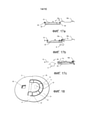
фиг.15a-c: другой примерный вариант осуществления системы укупорки, имеющей углубления в баночной крышке в качестве вентиляционных каналов;15a-c: another exemplary embodiment of a closure system having indentations in the jar lid as vents;
фиг.16a-c: разные примерные варианты осуществления углублений; иFig.16a-c: different exemplary embodiments of the recesses; And
фиг.17a-c: вид в сечении системы укупорки, имеющей углубления, для иллюстрации функции в качестве вентиляционных каналов;17a-c: cross-sectional view of a closure system having recesses to illustrate the function as ventilation ducts;
фиг.18: другой примерный вариант осуществления манипуляционного элемента;Fig.18: another exemplary embodiment of the manipulation element;
фиг.19: крышка, имеющая опциональные разгрузочные насечки;Fig.19: cover with optional discharge notches;
фиг. 20: другой вариант осуществления крышки для применения с системой укупорки;fig. 20: another embodiment of a closure for use with a closure system;
фиг.21: один из возможных вариантов осуществления закрывающего элемента для применения с крышкой с фиг.20;Fig. 21: one possible embodiment of a closure element for use with the lid of Fig. 20;
фиг.22: другой вариант осуществления крышки для применения с системой укупорки.22: Another embodiment of a closure for use with a closure system.
На фиг.1 изображается банка 2 для напитков в качестве примерного варианта осуществления емкости для напитков, имеющей предлагаемую изобретением систему 1 укупорки.1 shows a beverage can 2 as an exemplary embodiment of a beverage container having a
Показанная в качестве примера банка 2 для напитков может применяться для всех видов напитков, в частности для напитков, газированных напитков, таких как пиво, лимонады и энергетические напитки. Она обладает устойчивостью к внутреннему давлению по меньшей мере 6,2 бар. Она имеет неразъемную, по существу цилиндрическую емкость из алюминия или белой жести, а также, в качестве части системы 1 укупорки, соединенную в фальц крышку, например, из алюминия. Для соединения в фальц, например, отбортованный край банки может перегибаться один раз, а край крышки дважды, так чтобы возникающее соединение в фальц состояло всего из пяти охватывающих друг друга с геометрическим замыканием металлических слоев. Кроме банок для напитков, предлагаемая изобретением система 1 укупорки может применяться и для других видов упаковки, так, например, для картонных коробок для напитков или бутылок. На крышке зафиксированы другие компоненты системы укупорки.The exemplary beverage can 2 can be used for all types of beverages, in particular beverages, carbonated beverages such as beer, soft drinks and energy drinks. It has an internal pressure resistance of at least 6.2 bar. It has a one-piece, essentially cylindrical container made of aluminum or tinplate, as well as, as part of the
На фиг.2 показан первый примерный вариант осуществления системы 1 укупорки до установки на банку 2 для напитков с фиг.1. Она имеет, во-первых, саму крышку 10, верхняя сторона 12 которой здесь видна. Во-вторых, изображен манипуляционный элемент 30, который предусмотрен на верхней стороне 12 крышки и позволяет пользователю открывать банку вручную.FIG. 2 shows a first exemplary embodiment of the
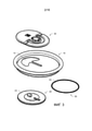
На фиг.3 показаны основные компоненты первого варианта осуществления системы 1 укупорки в покомпонентном изображении. Этими основными компонентами являются крышка 10, имеющая питьевое отверстие 14, манипуляционный элемент 30 и закрывающий элемент 20 для накрывания питьевого отверстия 14 с нижней стороны крышки.Figure 3 shows the main components of the first embodiment of the
Описанная система 1 укупорки может, с одной стороны, включать в себя закрывающий элемент 20 и манипуляционный элемент 30 (и при известных условиях уплотнительное кольцо 50), которые крепятся друг к другу вокруг надлежащей крышки 10, прежде чем эта крышка затем собирается с цилиндрическим корпусом с получением банки. С другой стороны, описанная система 1 укупорки может включать в себя также саму крышку 10.The
Дополнительно изображено опциональное уплотнительное кольцо 50, которое может состоять, например, из силикона или резины и может устанавливаться на закрывающем элементе 20. Когда закрывающий элемент, как здесь изображено, имеет насечку 23, уплотнительное кольцо может быть сформировано предпочтительно так, чтобы оно имело соответствующую форме насечки 23 вогнутость 53. Так как уплотнительное кольцо 50 может приходить в соприкосновение с напитком, оно предпочтительно выполнено безопасным для пищевых продуктов и без мягчителя. Опционально оно может иметь гидрофобную поверхность.An optional O-
Крышка 10, закрывающий элемент 20 и манипуляционный элемент 30 могут быть изготовлены из одного и того же материала, например, из алюминия. Изготовление может осуществляться посредством известных способов, например, посредством литья или штамповки. Но в частности, закрывающий элемент 20 и манипуляционный элемент 30 могут также состоять из неметаллических материалов, например, полимерных материалов. В качестве материала может применяться, в частности, поликарбонат; тогда компоненты могут изготавливаться, например, способом литья под давлением. Опционально закрывающий элемент 20 и манипуляционный элемент 30 могут выполняться прозрачными.The
Закрывающий элемент 20 и манипуляционный элемент 30 выполнены таким образом, что после компоновки через питьевое отверстие 14 они могут неподвижно соединяться друг с другом, например, посредством сварки, склеивания, крючка с зазубриной или других механических способов.Closing
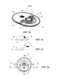
На фиг.4a-4d показан первый вариант осуществления закрывающего элемента 20. Фиг.4a представляет собой вид в перспективе закрывающего элемента 20, а на фиг.4b показан вид того же самого закрывающего элемента 20 в плане. На верхней стороне 21 предусмотрены углубление 26 и крепежный штифт 28 для соединения с манипуляционным элементом 30 (здесь не изображен). Наружное уплотнение 24 и внутреннее уплотнение 25 расположены концентрически и служат для уплотнения относительно нижней стороны крышки (здесь не изображено). При этом постоянное прижатие уплотнений 24 и 25 к нижней стороне крышки обеспечивает герметичное уплотнение. Опциональное центральное возвышение 27, в частности, когда манипуляционный элемент выполнен куполообразным, обеспечивает одинаковое расстояние между крышкой, с одной стороны, и верхней стороной закрывающего элемента 20 и нижней стороной манипуляционного элемента, с другой стороны. В показанном варианте осуществления закрывающий элемент 20 имеет насечку 23, уплотнения 24 и 25 соответственно тоже снабжены насечками. Насечка 23, крепежный штифт 28 и углубление 26 расположены вдоль первой оси A. Под прямым углом к ней проходит вторая ось B. На фиг.4c показано изображение в сечении закрывающего элемента 20 вдоль оси B, а на фиг.4d показано изображение в сечении по оси A. Изображена также обращенная к внутреннему пространству банки нижняя сторона 22 закрывающего элемента 20. Опционально может быть предусмотрено уплотнительное кольцо из силикона или резины (сравн. фиг.3) на уплотнениях 24 и 25 или, соответственно, между ними.4a-4d show a first embodiment of the
Закрывающий элемент 20 может быть, как изображено, округлым, но также иметь другие формы (например, иметь полукруглую или многоугольную форму). Эта форма может быть, например, по меньшей мере частично адаптирована к форме накрываемого питьевого отверстия. В частности, закрывающий элемент 20 может быть овальным или эллиптическим. Чтобы обеспечивать полное движение открывания закрывающего элемента 20 в направлении первой оси A, овальный или эллиптический закрывающий элемент предпочтительно является более широким вдоль второй оси B, чем вдоль первой оси A.The
На фиг.5a-5b показан первый вариант осуществления манипуляционного элемента 30. Фиг.5a представляет собой вид в перспективе верхней стороны 31 манипуляционного элемента 30. Вырез 38 вместе с крепежным штифтом закрывающего элемента (здесь не изображен) служит для соединения этих двух элементов. Вырез 38 может опционально иметь крючок с зазубриной, в который может застопориваться крепежный штифт 28. Альтернативно или дополнительно введенный в вырез 38 крепежный штифт 28 может фиксироваться привариванием или приклеиванием.FIGS. 5a-5b show a first embodiment of the handling
Манипуляционный элемент 30 имеет предохранительный или контрольный элемент 34. В одном из вариантов осуществления в виде контрольного элемента 34 он может, подобно своего рода печати качества, отображать целостность содержимого банки, пока система укупорки не была открыта. При открывании такой контрольный элемент 34 изменяется необратимо и визуально различимым образом. В частности, это позволяет пользователю простым образом различать, находится ли еще банка в оригинальном состоянии или была ли она уже открыта и снова закрыта.The handling
В показанном варианте осуществления предохранительный или контрольный элемент 34, который может быть выполнен округлым, соединен с основной частью манипуляционного элемента 30 посредством двух поперечных перемычек 35. Он имеет две контрольные перемычки 36, которые расположены ортогонально перемычкам 35 вращения, и которые выполнены для того, чтобы разрушаться при открывании системы укупорки.In the embodiment shown, the safety or
Поэтому перемычки 35 вращения являются опциональными. Альтернативно предохранительный или контрольный элемент 34 мог бы быть соединен с остальным манипуляционным элементом 30 также посредством шарнира (не показан).Therefore,
Так как элемент 34 может также выполнять только функцию предохранительного элемента, контрольные перемычки 36 также являются опциональными.Since
Изображена, кроме того, ручка 33, которая в виде лапки посредством действующей в качестве шарнира засечки 37 соединена с остальной частью манипуляционного элемента 30.In addition, a
На фиг.5b и 5c показано сечение манипуляционного элемента 30 и проиллюстрировано применение ручки для открывания системы укупорки. Ручка 33 предпочтительно имеет фаску для облегчения пользователю захвата и потягивания вверх ручки, прилегающей к баночной крышке. Вокруг шарнира 37 может осуществляться движение 7 поворота ручки 33, предпочтительно на угол до 135°. С помощью приподнятой таким образом ручки 33 манипуляционный элемент 30 путем потягивания 8 за ручку может просто выдвигаться вдоль оси A из своего первоначального закрытого положения для открывания банки.Figures 5b and 5c show a cross-section of the handling
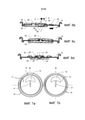
На фиг.6a показан первый вариант осуществления системы 1 укупорки на виде в плане. Изображены три оси A, B и C, при этом первая ось A проходит вдоль направления движения манипуляционного элемента, а оси B и C ортогонально ему. При этом ось B пересекает ось A на высоте крепежного штифта 28 закрывающего элемента и выреза 38 манипуляционного элемента, а ось C на высоте контрольного элемента 34 (сравн. фиг.4a и 5a). На фиг.6b, 6c и 6b показано соответственно изображение в сечении по одной из этих осей. При этом на фиг.6b показано сечение системы 1 укупорки вдоль первой оси A, на фиг.6c показано сечение вдоль оси B, а на фиг.6d показано сечение вдоль оси C.6a shows a first embodiment of the
Как можно различить на фиг.6b-d, манипуляционный элемент 30 установлен выше, а закрывающий элемент ниже крышки 10. Крепежный штифт 28 вставляется через питьевое отверстие крышки в вырез манипуляционного элемента 30 и способствует (например, посредством зацепления крючком, приваривания или приклеивания) прочному, без прокручивания соединению манипуляционного и закрывающего элемента. Альтернативно манипуляционный и закрывающий элемент могут быть также склепаны. Манипуляционный элемент 30 может быть выполнен куполообразным.As can be seen in FIGS. 6b-d, the handling
Манипуляционный элемент 30 действует предпочтительно как тарельчатая пружина, которая опирается в наружной области на крышку 10 и так отжимает среднюю область манипуляционного элемента от крышки 10. Благодаря этому предпочтительно закрывающий элемент 20, в частности его уплотнение 24 и/или его уплотнение 25, прижимается к нижней стороне 12 крышки 10. Средняя область может быть отодвинутой или вогнуто куполообразной относительно наружной области, в частности вверх. Манипуляционный элемент может наружной областью опираться на верхнюю сторону крышки 10.The handling
Контрольный элемент 34 лежит выше углубления 26 закрывающего элемента и соединен с манипуляционным элементом поперечными перемычками 35. Контрольные перемычки 36 соединяют контрольный элемент 34 с манипуляционным элементом вдоль первой оси A. Контрольный элемент 34 имеет на своей нижней стороне шиповидное возвышение 37, которое прилегает к баночной крышке 10 у края питьевого отверстия или на конце направляющей прорези питьевого отверстия (сравн. фиг.7a).The
При этом контрольный элемент 34 и его возвышение 39 размещены и устроены таким образом, что необходимое для открывания банки движение манипуляционного элемента вдоль первой оси A (движение 8 открывания) приводит к столкновению контрольного элемента 34 или, соответственно, возвышения 39, с верхней стороной баночной крышки 10, при этом осуществляется движение отклонения контрольного элемента 34. В качестве движения отклонения контрольного элемента 34 может осуществляться движение 5 вверх, движение 6 вращения вокруг оси C или комбинация этих двух движений 5, 6, например, как следствие крепления контрольного элемента 34 посредством опциональных поперечных перемычек 35. Вследствие такого движения отклонения, которое неизбежно инициируется посредством системы укупорки при открывании банки, контрольные перемычки 36 разрушаются. Поэтому открывание банки без разрушения контрольных перемычек по этому варианту осуществления предлагаемой изобретением системы укупорки исключено.In this case, the
Контрольные перемычки 36 имеют, в частности обусловленный производством, допуск, так что, чтобы можно было разрушить их и таким образом открыть банку, должна затрачиваться определенная сила. Тогда контрольный элемент размещен и выполнен таким образом, что движение 8 открывания создает движения 5, 6 отклонения, которое превышает этот допуск. Предпочтительно контрольные перемычки 36 могут иметь места предполагаемого разрушения. Для этого, например, каждая из контрольных перемычек 36 может иметь по существу треугольную форму, при этом один угол треугольника представляет собой соединение с контрольным элементом 34 и (как самое тонкое место контрольной перемычки 36) одновременно служит местом предполагаемого разрушения.The control bridges 36 have a manufacturing tolerance, in particular, so that a certain force must be expended in order to be able to destroy them and thus open the can. The control element is then positioned and designed in such a way that the
Крышка 10 может быть опционально куполообразной наружу (или, соответственно, вверх). Манипуляционный элемент 30 и/или закрывающий элемент 20 обладают в этом случае соответствующей куполообразностью. Это усиливает предпочтительно уплотнение с помощью закрывающего элемента 20.The
Как различимым образом изображено на фиг.6a-c, система укупорки выполнена с такими размерами, что возможность укладки в стопу нескольких снабженных этой системой укупорки баночных крышек не ухудшается. Также не ухудшается возможность укладки в стопу нескольких выполненных с такой баночной крышкой банок для напитков. В частности, манипуляционный элемент 30 и закрывающий элемент 20 выполнены каждый достаточно плоскими, чтобы обеспечивать обработку баночной крышки (включая систему укупорки) в существующих машинах и способах, в которых крышки устанавливаются на банку.As can be seen clearly in FIGS. 6a-c, the closure system is dimensioned such that the stacking capability of several jar lids provided with this closure system is not impaired. The possibility of stacking several beverage cans made with such a jar lid also does not deteriorate. In particular, the handling
На фиг.7a-b, 8a-b и 9a-b изображены разные примерные варианты осуществления крышки 10 или, соответственно, питьевых отверстий 14.7a-b, 8a-b and 9a-b show different exemplary embodiments of the
При этом на фиг.7a и 7b показан первый вариант осуществления. На фиг.7a показана баночная крышка 10 сверху. Изображена верхняя сторона 11 крышки, имеющая питьевое отверстие 14. По периметру вокруг верхней стороны находится край 13 фальца для соединения крышки 10 с банкой 2 (сравн. фиг.1). Этот край 13 фальца повышен относительно верхней стороны 11 крышки (глубина сердцевины). На фиг.7b показана нижняя сторона 12 той же самой крышки. Первый вариант осуществления крышки 10 имеет питьевое отверстие 14, имеющее направляющую прорезь 17, которая проходит вдоль оси A и задает направления движения для открывания и повторного закрывания банки. В частности, крепежный штифт закрывающего элемента может вставляться в направляющую прорезь 17 и при открывании банки направляться вдоль нее.Meanwhile, FIGS. 7a and 7b show the first embodiment. 7a shows the
На фиг.8a и 8b в качестве второго и третьего примерных вариантов осуществления крышки 10 показаны две модификации первого варианта осуществления фиг.7a и 7b. На фиг.8a питьевое отверстие 14 имеет напротив направляющей прорези 17 засечку 15. На фиг.8b рядом с питьевым отверстием напротив направляющей прорези предусмотрено маленькое отверстие 16. При этом засечка 15 и отверстие 16 размещены соответственно так, что они скрываются закрывающим элементом 20 (здесь не изображен), пока банка закрыта. Они могут быть предусмотрены дополнительно или альтернативно засечке 23 закрывающего элемента и позволяют, в частности в случае газированных напитков, плавно выравнивать избыточное давление в банке, когда она открывается. Для этого они предпочтительно расположены на первой оси A, так как там при движении открывания закрывающего элемента вдоль этой оси накрывание закрывающим элементом прекращается в первую очередь.Figures 8a and 8b show two modifications of the first embodiment of Figures 7a and 7b as second and third exemplary embodiments of the
На фиг.9a и 9b в качестве четвертого и пятого примерных вариантов осуществления крышки 10 показаны две модификации показанных на фиг.8a и 8b вариантов осуществления, имеющих засечку 15 или, соответственно, отверстие 16. В этих вариантах осуществления питьевое отверстие 14 является по существу круглым и выполнено без направляющей прорези. Но в принципе, могут применяться и разные другие, известные из уровня техники формы питьевого отверстия.In Figs. 9a and 9b, as fourth and fifth exemplary embodiments of the
На фиг.10a и 10b проиллюстрирован процесс открывания банки с помощью закрывающего элемента 20. При этом на фиг.10a показана крышка 10 с находящимся под ней закрывающим элементом 20 сверху, а на фиг.10b та же самая конфигурация снизу. Манипуляционный элемент 30 не изображен здесь только для лучшей обзорности. После движения 8 открывания закрывающего элемента 20 из его закрытого положения под питьевым отверстием 14 вдоль первой оси A закрывающий элемент 20 находится в положении питья, в котором питьевое отверстие 14 освобождено, и которое обеспечивает пользователю возможность питья или выливания содержимого банки.Figures 10a and 10b illustrate the process of opening a jar with a
На фиг.10b показана снизу нижняя сторона 22 закрывающего элемента 20 перед нижней стороной 12 баночной крышки. После движения 8 открывания питьевое отверстие 14 освобождено. Нижняя сторона 22 закрывающего элемента 20 приходит в соприкосновение с содержимым, и поэтому предпочтительно выполнена нечувствительной и безопасной для пищевых продуктов. Она может быть, в частности, выполнена гладкой и ровной. В этом примерном варианте осуществления нижняя сторона 22 (в противоположность верхней стоне 21) не имеет признаков, отличающихся возвышениями или углублениями.10b shows the
На фиг.10a показана верхняя сторона 11 баночной крышки 10, имеющая край 13 фальца и питьевое отверстие 14. Под ними (изображено штриховой линией, так как, собственно, скрыто баночной крышкой) находится закрывающий элемент 20, который своей верхней стороной 21 прилегает к баночной крышке и с помощью наружного уплотнения 24, внутреннего уплотнения 25, а также центрального возвышения 27 осуществляет уплотнение соответственно накрытой закрывающим элементом 20 части нижней стороны крышки. Можно различить, что крепежный штифт 28 в направляющей прорези питьевого отверстия направляется вдоль первой оси A.10a shows the
На фиг.11a и 11b проиллюстрирован (аналогично фиг.10a и 10b) процесс повторного закрывания банки. При этом на фиг.11a показана крышка 10 с находящимся под ней закрывающим элементом 20 сверху, а на фиг.11b та же самая конфигурация снизу. Манипуляционный элемент 30 здесь также только для лучшей обзорности не изображен. Закрывающий элемент 20 находится в своем закрытом положении под питьевым отверстием 14 и таким образом препятствует выходу содержимого банки. Это положение закрывающий элемент 20 принимает первоначально и после движения 9 закрывания, посредством которого банка может снова закрываться, после того, как она уже была открыта. Движение 9 закрывания проходит вдоль первой оси A и против движения 8 открывания (сравн. фиг.10a). Как можно видеть на фиг.11a, крепежный штифт 28 в закрытом положении закрывающего элемента 20 размещен в начале направляющей прорези.Figures 11a and 11b illustrate (similarly to Figures 10a and 10b) the process of reclosing a can. In this case, Fig. 11a shows the
На фиг.12a и 12b показан второй вариант осуществления манипуляционного элемента 30, имеющий альтернативный вариант осуществления контрольного элемента 40. При этом на фиг.12a манипуляционный элемент 30 показан сверху, а на фиг.12b снизу.Figures 12a and 12b show a second embodiment of the
Контрольный элемент 40 имеет запирающий элемент 41, который предусмотрен для того, чтобы при сборке системы укупорки застопориваться на крае крышки. Для этого запирающий элемент 41 закреплен на манипуляционном элементе посредством шарнира 43, который обеспечивает возможность этого застопоривания. Контрольный элемент 40 имеет две контрольные перемычки 42 на запирающем элементе 41. При движении манипуляционного элемента 30 от края баночной крышки эти контрольные перемычки 42 разрушаются, вследствие чего открывание банки остается видимым даже после повторного закрывания. На фиг.12a и 12b манипуляционный элемент 30 чисто в качестве примера изображен с двумя по-разному выполненными контрольными элементами 34 и 40. Альтернативно манипуляционный элемент 30, конечно, может быть оснащен также только одним из двух контрольных элементов или же каким-либо иначе выполненным контрольным элементом, который служит для той же самой цели, т.е. отображать пользователю, открывалась ли уже укупорочная система.The
На фиг.13a-13d изображен другой примерный вариант осуществления предлагаемой изобретением системы укупорки, причем эта система укупорки имеет альтернативный контрольный элемент.On figa-13d shows another exemplary embodiment of the closure system according to the invention, and this closure system has an alternative control element.
На фиг.13a показана крышка 10 этого варианта осуществления системы укупорки. Она изображена снизу, так что видна нижняя сторона 12, имеющая питьевое отверстие 14 и направляющую прорезь 17. В продолжение направляющей прорези 17 предусмотрено другое продолговатое отверстие 48.13a shows the
На фиг.13b показан закрывающий элемент 20 этого варианта осуществления системы укупорки. На верхней стороне 21 предусмотрены углубление 26 и крепежный штифт 28 для соединения с манипуляционным элементом 30 (здесь не изображен). Наружное уплотнение 24 и внутреннее уплотнение 25 служат для уплотнения относительно нижней стороны крышки (здесь не изображена). В отличие от варианта осуществления, изображенного на фиг.4a, показанный здесь закрывающий элемент 20 дополнительно имеет контрольный элемент 45 в виде стержня. Этот контрольный стержень 45 установлен на крае углубления 26. Стержень 45 и углубление 26 выполнены с такими размерами, что стержень подходит к углублению. Хотя контрольный стержень 45 изображен здесь цилиндрическим, он может также иметь другую форму. Так, он может быть выполнен, в частности, коническим, в форме полуцилиндра или в форме прямоугольного параллелепипеда. Стержень 45 размещен на закрывающем элементе 20 так, что он в закрытом положении закрывающего элемента 20, т.е. в положении, в котором закрывающий элемент 20 накрывает питьевое отверстие 14, вставляется в продолговатое отверстие 48 крышки 10 (см. фиг.13a).13b shows the
На фиг.13c и 13d показан манипуляционный элемент 30 этого варианта осуществления системы укупорки сверху и снизу. На фиг.13c показана верхняя сторона 31 манипуляционного элемента 30. В отличие от варианта осуществления, изображенного на фиг.5a, показанный здесь манипуляционный элемент 30 не имеет контрольного элемента. Вместо этого предусмотрено смотровое отверстие 46, которое размещено выше контрольного стержня 45 закрывающего элемента 20, когда манипуляционный элемент 30 и закрывающий элемент 20 соединены друг с другом, например, неподвижно соединены посредством крепежного штифта 28 и выреза 38.13c and 13d show the handling
Кроме того, манипуляционный элемент 30 имеет контрольные перемычки 44, которые соединяют основную часть манипуляционного элемента с ручкой 33 и предусмотрены для того, чтобы разрушаться при приподнятии ручки 33 (сравн. фиг.5a-c), и так уже делать необратимо видимым приподнятие ручки 33. Разумеется, что этот вариант осуществления ручки 33 может также комбинироваться с вариантами осуществления манипуляционного элемента 30, представленными ранее.In addition, the
На фиг.13d показана нижняя сторона 32 манипуляционного элемента 30. Различимо снабженное фаской углубление 47 у смотрового отверстия 46, которое размещено выше углубления 26 закрывающего элемента 20, когда манипуляционный элемент 30 и закрывающий элемент 20 соединены друг с другом.13d shows the
Показанный на фиг.13a-d вариант осуществления системы укупорки имеет альтернативную систему контроля, чтобы делать оригинально закрытую банку заметно отличающейся от повторно закрытой. При этом контрольный стержень 45 выполняет функцию контрольного элемента. В оригинально закрытом состоянии контрольный стержень 45 через отверстие 48 крышки вставляется в смотровое отверстие 46 в манипуляционный элемент 30 и виден там потребителю. Предпочтительно верхняя сторона контрольного стержня 45 может быть выполнена цветной для улучшения видимости. При движении открывания контрольный стержень 45 наталкивается на баночную крышку 10 и разрушается. Предпочтительно контрольный стержень 45 может иметь место предполагаемого разрушения, чтобы не разрушаться неконтролируемым образом и при известных условиях не блокировать процесс открывания. Разрушенный контрольный стержень 45 посредством имеющего фаску углубления 47 в нижней стороне 32 манипуляционного элемента 30 и посредством движения открывания наклоняется и ложится в углублении 26 на верхнюю сторону 22 закрывающего элемента 20. Поэтому контрольный стержень больше не виден в смотровое отверстие. Альтернативно стороны контрольного стержня 45 может быть выполнены другого цвета, чем верхняя сторона, так чтобы осуществленное открывание было различимо по цвету в смотровом отверстии 46.The embodiment of the closure system shown in FIGS. 13a-d has an alternative control system to make an originally closed can distinctly different from a reclosed one. When this
В частности, в этом варианте осуществления закрывающий элемент 20, наряду с показанной округлой, может иметь также овальную или эллиптическую форму.In particular, in this embodiment, the
На фиг.14a-c показан второй примерный вариант осуществления закрывающего элемента 20. На фиг.14a закрывающий элемент 20 изображен сверху, так что видна верхняя сторона 21 с расположенными на ней (и уже показанными со ссылкой на фиг.4a-d или, соответственно, фиг.13b) признаками. Эти признаки включают в себя наружное уплотнение 24 и внутреннее уплотнение 25, имеющее насечку 23, углубление 26, центральное возвышение 27 и крепежный штифт 28. Кроме того, здесь контрольный стержень 45 является частью закрывающего элемента 20. Помимо этого, закрывающий элемент 20 имеет в этом варианте осуществления контурную область 29, которая придает закрывающему элементу в целом овальную форму. Эта контурная область 29 адаптирована по форме и размеру к баночной крышке. Благодаря тому, что закрывающий элемент вдоль оси B гораздо длиннее, чем вдоль ортогонального ей направления открывания, продолжает обеспечиваться полное открывание системы укупорки. Это изображено на фиг.14b и 14c. Однако уплотнения 24 и 25 расположены по кругу и охватывают область, которая достаточно велика, чтобы полностью накрывать питьевое отверстие в крышке. Опционально (сравн. фиг.3) возле уплотнений 24 и 25 или, соответственно, между ними может быть предусмотрено уплотнительное кольцо.14a-c show a second exemplary embodiment of the
На фиг.14b и 14c показана система 1 укупорки, имеющая закрывающий элемент с фиг.14a, снизу. Видна соответственно нижняя сторона 12 баночной крышки и нижняя сторона 22 закрывающего элемента. На фиг.14b закрывающий элемент находится в закрытом положении - питьевое отверстие полностью накрыто. На фиг.14c банка открыта. Закрывающий элемент был выдвинут вдоль первой оси A из закрытого положения, так что питьевое отверстие 14 освобождено. Изображена также соответственно насечка 23, которая расположена на первой оси A и при смещении закрывающего элемента вдоль первой оси A представляет собой первое отверстие ниже питьевого отверстия 14, так что здесь имеющееся, в частности, в случае газированных напитков, избыточное давление внутри банки может выравниваться особенно плавно. Адаптированная к баночной крышке форма закрывающего элемента улучшает, с одной стороны, стабильность системы 1 укупорки, а с другой стороны, препятствует избыточному движению открывания или, соответственно, повторного закрывания системы укупорки.Figures 14b and 14c show a
На фиг.15a-c показан другой примерный вариант осуществления системы 1 укупорки. Изображена эта система укупорки соответственно снизу, так что видны нижняя сторона 12 баночной крышки и нижняя сторона 22 закрывающего элемента. Закрывающий элемент здесь чисто в качестве примера является показанным на фиг.14a-c. По этому варианту осуществления баночная крышка имеет одно или несколько углублений 18, которые могут быть выполнены, например, продолговатыми. Они могут изготавливаться в верхней или нижней стороне крышки, например, посредством штамповки или чеканки. Эти, выполняемые также в виде пазов или канавок, деформации служат, с одной стороны, для повышенной стабильности и прочности крышки. С другой стороны, они могут служить в качестве вентиляционных каналов для газообмена, так что этот вариант осуществления не имеет насечек на закрывающем элементе или у питьевого отверстия. При первом открывании емкости воздух может контролируемым образом улетучиваться из банки, а при питье наружный воздух может втекать в банку. Но углубления могут также комбинироваться с насечками.On figa-c shows another exemplary embodiment of the
На фиг.15a закрывающий элемент находится в закрытом положении - питьевое отверстие полностью накрыто, продолговатые углубления 18 не затрагиваются закрывающим элементом, так что не возможен ни газообмен, ни выход жидкости.In Fig. 15a the closing element is in the closed position - the drinking opening is completely covered, the
На фиг.15b показан закрывающий элемент во время движения 8 открывания вдоль первой оси A. Питьевое отверстие еще полностью накрыто, но закрывающий элемент уже был сдвинут под углубления 18. Как только закрывающий элемент своей уплотнительной областью частично покроет одно из углублений 18, через не накрытую часть этого по меньшей мере одного углубления 18 и еще покрытое питьевое отверстие может происходить газообмен 7a между внутренним пространством банки и окружающей средой, при этом углубление служит вентиляционным каналом. Таким образом предпочтительно имеющееся, в частности у газированных напитков, избыточное давление внутри банки может выравниваться особенно плавно и еще до открывания питьевого отверстия 14.15b shows the closure element during the
На фиг.15c банка полностью открыта. Закрывающий элемент был выдвинут вдоль первой оси A из закрытого положения, так что питьевое отверстие 14 освобождено. При этом углубления 18 частично накрыты закрывающим элементом, так что газообмен 7b между окружающей средой и внутренней областью банки может осуществляться не только через питьевое отверстие, но и через углубления 18, которые служат вентиляционным каналом. Таким образом может предпочтительно выравниваться возникающее при питье или выливании избыточное давление внутри банки. Предпочтительно это улучшает свойства выливания. Питье или выливание содержимого банки через питьевое отверстие может осуществляться как равномернее, так и быстрее. Так как выходящая из банки жидкость равномерно посредством углублений 18 может заменяться воздухом из окружающей среды, для протекания жидкости по меньшей мере большая часть питьевого отверстия 14, в частности все питьевое отверстие 14 доступно для протекания жидкости.In Fig. 15c, the jar is fully open. The closing element has been extended along the first axis A from the closed position so that the
Углубления 18 по своим размерам, поверхности, форме, количеству и положениям предпочтительно рассчитаны на то, чтобы обеспечивать контролируемый оптимальный газообмен 7a, 7b между внутренним пространством банки и окружающей средой. Оптимизация варианта осуществления углублений должна предпочтительно учитывать контролируемый, как можно более плавный выход 7a газа при открывании банки, в частности в случае газированных напитков, и/или как можно более интенсивный вход 7b воздуха в банку, во время питья содержимого банки или переливания через питьевое отверстие 14.The
Для этого оптимизированные для выхода 7a углубления 18 могут комбинироваться с оптимизированными для входа 7b углублениями 18 (при этом, однако, может быть достаточно и одного вида углублений - для выхода или входа). Оптимизированные для выхода 7a углубления могут быть размещены так, чтобы они достигались закрывающим элементом сразу после начала процесса открывания и выполняли функцию вентиляционного канала, но при полном открывании были полностью накрыты закрывающим элементом. Оптимизированные для входа 7b углубления, напротив, могут быть размещены так, чтобы они достигались закрывающим элементом и выполняли функцию вентиляционного канала только при полном открывании.To this end, the
На фиг.16a-c проиллюстрированы разные формы и расположения углублений 18ʽ, 18ʽʽ, 18ʽʽʽ. И здесь изображена нижняя сторона 12 баночной крышки вместе с нижней стороной 22 закрывающего элемента. Чисто в качестве примера здесь изображены каплеобразные углубления 18ʽ, ромбовидные углубления 18ʽʽ, а также дугообразное углубление 18ʽʽʽ. Наряду с углублениями, расположенными параллельно направлению открывания, возможны также радиальные расположения.16a-c illustrate different shapes and arrangements of recesses 18', 18'', 18''. Here again, the
Кроме геометрических форм могут также применяться углубления, имеющие более сложные рисунки, в частности фигуры логотипы или надписи, которые создают связь с содержимым банки или информируют о нем. Эти рисунки могут содержать, например, фирменный знак изготовителя или информацию об объеме наполнения или дате окончания срока хранения. Возможна комбинация таких рисунков с формами углублений, оптимизированными для газообмена 7a, 7b. Однако, в принципе, форма и расположение углубления или, соответственно, углублений может варьироваться, пока ими создается вентиляционный канал, который обходит уплотнение закрывающего элемента.In addition to geometric shapes, recesses with more complex designs, in particular logo shapes or inscriptions, can also be used, which create a connection with the contents of the can or inform about it. These drawings may contain, for example, the manufacturer's logo or information about the filling volume or expiration date. It is possible to combine such patterns with recess shapes optimized for
Либо нижняя сторона 12 крышки может иметь одно или несколько углублений 18, 18ʽ, 18ʽʽ, 18ʽʽʽ, так что верхняя сторона 11 имеет соответствующие возвышения, либо одно или несколько углублений 18, 18ʽ, 18ʽʽ, 18ʽʽʽ имеются в верхней стороне 11 крышки и соответственно на нижней стороне 12 имеются один или несколько признаков возвышения. В последнем случае закрывающий элемент может быть выполнен для того, чтобы с помощью одного или нескольких возвышений при движении открывания немного (например, до 1 мм) приподниматься от нижней стороны крышки, так чтобы газообмен 7a, 7b осуществлялся всегда через промежутки между возвышениями или между уплотнением и нижней стороной 12 крышки.Either the
На фиг.17a-c показан один из примерных вариантов осуществления системы укупорки, имеющей углубления в баночной крышке, на изображении в сечении. Видна соответственно крышка 10, имеющая питьевое отверстие 14 и два углубления 18a и 18b. Эти углубления изготовлены в нижней стороне крышки, так что на верхней стороне они представляют собой возвышения. Ниже крышки показан закрывающий элемент 20, который контактирует с нижней стороной крышки своим уплотнительным кольцом 50. Закрывающий элемент здесь для обзорности не изображен.17a-c show one exemplary embodiment of a closure system having depressions in a jar lid, in cross section. A
На фиг.17a закрывающий элемент 20 находится в своем закрытом положении ниже питьевого отверстия 14 и накрывает его. Углубления 18a и 18b в этом положении не затрагиваются закрывающим элементом 20.In Fig. 17a, the closing
На фиг.17b показана ситуация, в которой начался процесс открывания. Закрывающий элемент 20 движется в направлении 8 открывания и достигает первого углубления 18a, вследствие чего возникает вентиляционный канал, через который может осуществляться газообмен 7a изнутри банки в окружающую среду, так что избыточное давление в банке может нарастать или уменьшаться, прежде чем закрывающий элемент 20 освободит питьевое отверстие 14.17b shows the situation in which the opening process has started. The closing
На фиг.17c показана система укупорки в открытом состоянии. Питьевое отверстие 14 преобладающим образом свободно, закрывающий элемент покрывает только небольшую часть отверстия 14 - эта часть может также, например, быть направляющей прорезью питьевого отверстия (см., например, фиг.7a, b). Закрывающий элемент накрывает второе углубление 18b, так что возникает вентиляционный канал. Теперь, при питье или опорожнении жидкого содержимого банки, в частности путем наклона банки, оно течет из банки, следуя силе тяжести, через питьевое отверстие 14 (иллюстрировано стрелкой 4). Поэтому в банке может возникать недостаточное давление, которое может негативным образом уменьшать скорость течения. Однако через вентиляционный канал второго углубления 18b может осуществляться вход 7b газа в банку, благодаря чему недостаточное давление может предпочтительно выравниваться.17c shows the closure system in an open state. The
Предпочтительно первое углубление 18a по своим размерам, форме, положению, ориентации, поверхностной структуре выполнено для оптимального выхода 7a газа. Точно так же углубление 18b по своим размерам, форме, положению, ориентации, поверхностной структуре выполнено для оптимального входа 7b газа. Альтернативно, конечно, может применяться углубление, которое имеет признаки, обеспечивающие желаемым образом как выход 7a газа, так и вход 7b газа.Preferably, the
Закрывающий элемент 20 может предпочтительно иметь углубления, ответные углублениям в крышке, причем эти углубления, в зависимости от положения закрывающего элемента 20, образуют различно выполненные вентиляционные каналы для наиболее оптимального возможного направления газообмена 7a, 7b. Точно так же манипуляционный элемент предпочтительно выполнен так, чтобы не создавалось препятствия газообмену 7a, 7b, или, соответственно, выполнен так, чтобы газообмен 7a, 7b поддерживался и осуществлялся по возможности контролируемым образом. Так, также манипуляционный элемент может иметь вентиляционные каналы, или, соответственно, образовывать вентиляционные каналы вместе с закрывающим элементом 20. Например, такой выход 7a газа может быть целенаправлен в окружающую среду, в частности отведен от пользователя банки, например, ортогонально направлению открывания. Закрывающий элемент 20 и манипуляционный элемент могут быть также выполнены для того, чтобы воспринимать избыточное давление внутри банки и регулируемым образом отдавать в окружающую среду.The
Процесс открывания может опционально замедляться одним или несколькими механическими сопротивлениями (здесь не изображены), когда закрывающий элемент находится в определенном положении, чтобы оптимально выполнить выход 7a газа. Эти сопротивления могут быть выполнены, например, в виде возвышений в крышке, на которые манипуляционный элемент или закрывающий элемент наталкиваются во время процесса открывания. Указанное или указанные сопротивления, посредством которых первое открывание укупорки становится различимо для пользователя, могут также создаваться, в частности, контрольным элементом (сравн. фиг.5a, 12a, 13b).The opening process can optionally be slowed down by one or more mechanical resistances (not shown here) when the closing element is in a certain position in order to optimally carry out the
Эти сопротивления могут приводить к небольшому замедлению процесса открывания в определенном положении. Оно может выбираться так, чтобы могло выходить определенное количество газа, прежде чем открывается питьевое отверстие 14. Но сопротивления могут также создавать сопротивление, заметное для открывающего укупорку пользователя. В этом случае пользователь может ожидать выхода воздуха из банки, в частности полного падения избыточного давления, до продолжения им процесса открывания.These resistances can lead to a slight delay in the opening process in a certain position. It can be chosen so that a certain amount of gas can escape before the
Опционально вентиляционный канал в закрывающем элементе или в манипуляционном элементе может выполняться таким образом, чтобы посредством выхода 7a газа создавался акустический сигнал, например, наподобие свистка или флейты. Пользователь может, например, по силе звука этого сигнала различать, действует ли еще в банке избыточное давление, и в зависимости от этого продолжать процесс открывания.Optionally, the ventilation duct in the closure element or in the handling element can be designed in such a way that an acoustic signal, for example like a whistle or a flute, is generated by means of the
На фиг.18 показан другой примерный вариант осуществления манипуляционного элемента 30, который может комбинироваться с описанным выше закрывающим элементом 20.FIG. 18 shows another exemplary embodiment of a
Предохранительный и/или контрольный элемент 34 соединен в этом случае с остальным манипуляционным элементом 30 посредством шарнира 70, в частности с участком манипуляционного элемента 30, на котором предусмотрено соединение с закрывающим элементом (здесь область, в которой предусмотрен вырез 38 для помещения крепежного штифта 28; но вместо выреза 38 могут выбираться и другие виды соединения, например, как описано выше). Предохранительный и/или контрольный элемент 34 опционально соединен с ручкой 33, например, соединен неподвижно (например, посредством жесткого участка 71) или посредством одной или нескольких контрольных перемычек 44, которые разрушаются при приподнятии ручки 33.The safety and/or
На нижней стороне предохранительного и/или контрольного элемента 34 предусмотрено предпочтительно возвышение 39 (здесь, так как оно скрыто, обозначено штриховой линией), которое, в частности, может быть выполнено в виде крючка.On the lower side of the safety and/or
На фиг.19 показан другой опциональный признак крышки 12 для применения с системой укупорки. Как здесь показано, направляющая прорезь 17 на своем обращенном от питьевого отверстия 14 конце может иметь по меньшей мере одну или несколько разгрузочных насечек 72. Обращенный от него конец может быть задним концом направляющей прорези 17. Разгрузочные насечки 12 могут образовывать радиус в углах в остальном прямоугольного поперечного сечения направляющей прорези 17. Разгрузочные насечки 72 могут быть выштампованы, например, так, чтобы этот конец направляющей прорези 17 не имел прямого угла. Благодаря этому при высоких внутренних давлениях может предупреждаться надрыв крышки 12 и/или лопание крышки 12.FIG. 19 shows another
Эти одна или несколько разгрузочных насечек 72 распространяются предпочтительно по существу перпендикулярно продольному направлению направляющей прорези 17. Данная разгрузочная насечка 72 предпочтительно искривлена, при этом средняя точка круга кривизны предпочтительно лежит ближе к средней точке крышки 12, чем разгрузочная насечка 72. Данная разгрузочная насечка 72 может быть выполнена, например, дугообразно. Длина разгрузочной насечки 72, в частности длина дуги, может быть больше ширины направляющей прорези 17 перпендикулярно ее продольной оси. Как будет нетрудно различить специалисту, такие разгрузочные насечки 72 могут применяться с каждой из вышеописанных крышек 12.These one or
На фиг.20 и 22 показаны другие оптимальные признаки и варианты осуществления крышки 12, которые могут находить применение в комбинации с разгрузочными насечками или независимо от них. При этом крышка имеет по меньшей мере одно первое углубление 18A или несколько углублений 18A, которые во время открывания закрывающего элемента 20 и/или в его открытом положении могут образовывать первый вентиляционный канал, как уже описано выше.On Fig and 22 show other optimal features and options for the implementation of the
Указанное по меньшей мере одно первое углубление 18A расположено так, что оно в закрытом положении закрывающего элемента 20 расположено внутри уплотнения (на фиг.20 и 22 не показано; см. уплотнительное кольцо 50 на фиг.17a-17c).Said at least one
Указанное по меньшей мере одно первое углубление 18A предпочтительно расположено так, что оно в закрытом положении перекрывается закрывающим элементом 20 (на фиг.20 и 22 не показано) и/или манипуляционным элементом 30, предпочтительно полностью.Said at least one
При перестановке закрывающего элемента 20 в открытое положение достигается предпочтительно положение, в частности промежуточное положение, в котором уплотнение 50 и/или закрывающий элемент 20 перекрывает указанное по меньшей мере одно первое углубление 18A. Так может достигаться выравнивание давления, в частности начальное выравнивание давления при открывании системы укупорки. Указанное по меньшей мере одно первое углубление 18A может быть расположено так, чтобы оно в открытом положении полностью перекрывалось закрывающим элементом 20 и/или полностью было расположено внутри уплотнения 50.By shifting the
В комбинации с указанным по меньшей мере одним первым углублением 18A или независимо от него крышка 12 может иметь по меньшей мере одно второе углубление 18B. Оно предпочтительно расположено так, что оно в закрытом положении не скрывается закрывающим элементом 20 и/или в закрытом положении не расположено внутри уплотнения 50, даже частично. Указанное по меньшей мере одно второе углубление 18B в закрытом положении предпочтительно не скрыто манипуляционным элементом 30. В открытом положении указанное по меньшей мере одно второе углубление предпочтительно частично (в частности, только частично) перекрывается закрывающим элементом 20 и/или уплотнением 50 и/или манипуляционным элементом 30.In combination with or independently of said at least one
Второе углубление может быть выполнено, например, в виде одного или нескольких углублений 18B, которое расположено в направлении смещения манипуляционного элемента 30 позади манипуляционного элемента 30 (см. фиг.20) и/или рядом с манипуляционным элементом 30 (см. фиг.22).The second recess can be made, for example, in the form of one or
Как описано выше, указанное по меньшей мере одно первое углубление 18A и/или указанное по меньшей мере одно второе углубление 18B могут выступать вверх или вниз. Указанное по меньшей мере одно первое углубление 18A и/или указанное по меньшей мере одно второе углубление 18B может быть выполнено, в частности, в виде чеканки.As described above, said at least one
В комбинации с указанным по меньшей мере одним первым углублением 18A и/или указанным по меньшей мере одним вторым углублением 18B или независимо от них крышка 12 может также иметь одно или несколько (в частности, два) третьих углубления 19. Они могут взаимодействовать с одним или несколькими соответствующими выступами 73 на верхней стороне закрывающего элемента 20 (см. фиг.21) для создания продольной направляющей и/или предохранителя от прокручивания для закрывающего элемента 20. Поэтому углубление 19 предпочтительно выступает вверх. Оно может быть выполнено в виде чеканки в крышке 12.In combination with or independently of said at least one
Разумеется, что представленные фигуры только схематично изображают возможные примеры осуществления. Разные методы могут точно так же комбинироваться друг с другом, а также с устройствами, например, емкостями для напитков, уровня техники.Of course, the figures shown are only schematic representations of possible embodiments. The different methods can be combined with each other in the same way, as well as with prior art devices, such as beverage containers.
Хотя выше описываются, в частности, банка и баночная крышка, раскрытая система укупорки может также устанавливаться на других емкостях для жидкостей или сыпучего материала. Такие емкости для жидкостей могут быть изготовлены, например, из картона, пластика и/или металла. Это относится, в частности, к емкостям, которые по меньшей мере в области выливного отверстия изготовлены из материала, обладающего достаточной жесткостью. Названная в настоящем случае крышка у емкости для жидкости может быть заменена, например, стенкой емкости и/или образовываться такой стенкой.Although the can and can lid are described in particular above, the disclosed closure system can also be installed on other containers for liquids or bulk material. Such containers for liquids can be made of, for example, cardboard, plastic and/or metal. This applies in particular to containers which, at least in the area of the pouring opening, are made of a material that is sufficiently rigid. The lid of the liquid container, named in the present case, can be replaced by, for example, a wall of the container and/or be formed by such a wall.
Изобретение касается, в том числе, следующих аспектов:The invention relates, inter alia, to the following aspects:
1. Система (1) укупорки для емкости для жидкостей (в частности напитков) и/или сыпучего материала, в частности банки (2) для напитков или картонной коробки, имеющая1. A closure system (1) for a container for liquids (in particular drinks) and / or bulk material, in particular a can (2) for drinks or a cardboard box, having
- закрывающий элемент (20) для закрывания питьевого отверстия (14) крышки (10) емкости для напитков и- a closing element (20) for closing the drinking opening (14) of the lid (10) of the beverage container and
- манипуляционный элемент (30) для открывания питьевого отверстия (14) вручную пользователем,- a manipulation element (30) for opening the drinking hole (14) manually by the user,
отличающаяся тем, чтоcharacterized in that
- закрывающий элемент (20) может размещаться на нижней стороне (12) крышки (10) и может неподвижно соединяться с манипуляционным элементом (30) на верхней стороне (11) крышки (10);- the closing element (20) can be placed on the lower side (12) of the lid (10) and can be fixedly connected to the handling element (30) on the upper side (11) of the lid (10);
- закрывающий элемент (20) для закрывания питьевого отверстия (14) выполнен для того, чтобы в закрытом положении по всей площади накрывать питьевое отверстие (14); и- the closing element (20) for closing the drinking hole (14) is designed to cover the drinking hole (14) in the closed position over the entire area; And
- манипуляционный элемент (30) и закрывающий элемент (20) расположены с возможностью движения воль первой оси (A), которая проходит по существу параллельно верхней стороне (11) крышки (10), при этом- the handling element (30) and the closing element (20) are movable in the first axis (A), which runs essentially parallel to the upper side (11) of the cover (10), while
- движение манипуляционного элемента (30) в первом направлении (8) вдоль первой оси (A) может вызывать движение закрывающего элемента (20) из закрытого положения и открывание питьевого отверстия (14), а- movement of the manipulation element (30) in the first direction (8) along the first axis (A) can cause the closing element (20) to move from the closed position and open the drinking hole (14), and
- движение манипуляционного элемента (30) в противоположном первому направлению (8) втором направлении (9) вдоль первой оси (A) может вызывать движение закрывающего элемента (20) в закрытое положение и повторное закрывание питьевого отверстия (14).- movement of the manipulation element (30) in the opposite direction (8) to the second direction (9) along the first axis (A) can cause the closing element (20) to move to the closed position and re-close the drinking hole (14).
2. Система укупорки (1) по аспекту 1, имеющая крышку (10), причем эта крышка имеет верхнюю сторону (11), нижнюю сторону (12) и питьевое отверстие (14),2. The closure system (1) according to
отличающаяся тем, чтоcharacterized in that
- закрывающий элемент (20) размещен на нижней стороне (12) крышки (10) и неподвижно соединен с манипуляционным элементом (30) на верхней стороне (11) крышки (10); и- the closing element (20) is located on the lower side (12) of the cover (10) and is fixedly connected to the handling element (30) on the upper side (11) of the cover (10); And
- манипуляционный элемент (30) и закрывающий элемент (20) расположены с возможностью движения вдоль первой оси (A), при этом- manipulation element (30) and closing element (20) are located with the possibility of movement along the first axis (A), while
- движение манипуляционного элемента (30) в первом направлении (8) вдоль первой оси (A) вызывает движение закрывающего элемента (20) из закрытого положения и открывание питьевого отверстия (14), а- the movement of the manipulation element (30) in the first direction (8) along the first axis (A) causes the movement of the closing element (20) from the closed position and the opening of the drinking hole (14), and
- движение манипуляционного элемента (30) в противоположном первому направлению (8) втором направлении (9) вдоль первой оси (A) вызывает движение закрывающего элемента (20) в закрытое положение и повторное закрывание питьевого отверстия (14).- movement of the handling element (30) in the opposite direction (8) to the second direction (9) along the first axis (A) causes the closing element (20) to move to the closed position and re-closing the drinking hole (14).
3. Система укупорки (1) по аспекту 1 или аспекту 2,3. Capping system (1) according to
отличающаяся тем, чтоcharacterized in that
система укупорки имеет по меньшей мере один контрольный элемент (34, 40, 45), причем этот контрольный элемент выполнен таким образом, что онthe closure system has at least one control element (34, 40, 45), and this control element is designed in such a way that it
- имеет первое состояние, пока манипуляционный элемент (30) не движется, и/или закрывающий элемент (20) не движется из закрытого положения, и- has a first state until the manipulation element (30) is moving and/or the closing element (20) is moving from the closed position, and
- необратимо принимает по меньшей мере визуально отличающееся от первого состояния второе состояние, когда манипуляционный элемент (30) движется в первом направлении (8), и/или закрывающий элемент (20) движется из закрытого положения,- irreversibly assumes a second state at least visually different from the first state when the manipulation element (30) moves in the first direction (8) and/or the closing element (20) moves from the closed position,
в частности, при этомin particular, while
- контрольный элемент (34, 40, 45) сохраняет второе состояние даже тогда, когда манипуляционный элемент (30) движется обратно во втором направлении (9), и/или закрывающий элемент (20) движется обратно в закрытое положение; и/или- the control element (34, 40, 45) maintains the second state even when the manipulation element (30) moves back in the second direction (9) and/or the closing element (20) moves back to the closed position; and/or
- манипуляционный элемент (30) выполнен цельно с контрольным элементом (34), в частности при этом манипуляционный элемент (30) и контрольный элемент (34) состоят из алюминия.- the manipulation element (30) is integral with the control element (34), in particular the manipulation element (30) and the control element (34) are made of aluminium.
4. Система укупорки (1) по аспекту 3,4. Capping system (1) according to aspect 3,
отличающаяся тем, чтоcharacterized in that
контрольный элемент (34, 40) имеет по меньшей мере одну, расположенную видимым снаружи образом, контрольную перемычку (36, 42), которая расположена и устроена таким образом, что она разрушается, когда манипуляционный элемент (30) движется в первом направлении (8), и/или закрывающий элемент (20) движется из закрытого положения,the control element (34, 40) has at least one control bridge (36, 42) located and arranged in such a way that it is visible from the outside, which is located and arranged in such a way that it is destroyed when the manipulation element (30) moves in the first direction (8) , and/or the closing element (20) moves from the closed position,
в частности, при этом указанная по меньшей мере одна контрольная перемычка (36, 42) имеет место предполагаемого разрушения.in particular, said at least one control jumper (36, 42) is in the place of the alleged destruction.
5. Система укупорки (1) по аспекту 4,5. Capping system (1) according to
отличающаяся тем, чтоcharacterized in that
контрольный элемент (34) расположен и устроен таким образом, что движение манипуляционного элемента (30) в первом направлении (8) вызывает движение (5, 6) отклонения контрольного элемента (34), посредством которого осуществляется разрушение указанной по меньшей мере одной контрольной перемычки (36), в частности при этомthe control element (34) is located and arranged in such a way that the movement of the manipulation element (30) in the first direction (8) causes the movement (5, 6) of the deviation of the control element (34), through which the destruction of the specified at least one control jumper ( 36), in particular
- контрольный элемент (34) установлен на манипуляционном элементе (30) посредством двух поперечных перемычек (35), которые обеспечивают возможность движения контрольного элемента (34) вокруг оси (C) наклона, ортогональной первой оси (A),- the control element (34) is mounted on the manipulation element (30) by means of two transverse bridges (35), which allow the control element (34) to move around the tilt axis (C), orthogonal to the first axis (A),
- указанная по меньшей мере одна контрольная перемычка (36) проходит вдоль первой оси (A), в частности, при этом указанная по меньшей мере одна контрольная перемычка (36) закреплена на контрольном элементе (34) и на манипуляционном элементе (30),- the specified at least one control jumper (36) runs along the first axis (A), in particular, while the specified at least one control jumper (36) is fixed on the control element (34) and on the manipulation element (30),
- контрольный элемент (34) расположен таким образом, что при движении манипуляционного элемента (30) в первом направлении (8) он сталкивается с крышкой (10), при этом движение (5, 6) отклонения по меньшей мере частично вызывается этим столкновением, и- the control element (34) is located in such a way that when the manipulation element (30) moves in the first direction (8), it collides with the cover (10), while the deviation movement (5, 6) is at least partially caused by this collision, and
- движение отклонения включает в себя наклон (6) контрольного элемента (34) вокруг оси (C) наклона;- the movement of the deviation includes the tilt (6) of the control element (34) around the axis (C) tilt;
в частности, при этом контрольный элемент (34) на своей нижней стороне имеет возвышение (39), которое расположено таким образом, что при движении манипуляционного элемента (30) в первом направлении (8) оно сталкивается с крышкой (10), в частности при этомin particular, in this case, the control element (34) on its lower side has an elevation (39), which is located in such a way that when the manipulation element (30) moves in the first direction (8), it collides with the cover (10), in particular when this
- движение (5, 6) отклонения по меньшей мере частично вызывается этим столкновением;- the deflection movement (5, 6) is at least partially caused by this collision;
- возвышение (39) прилегает к крышке (10) у края питьевого отверстия (14) или на конце направляющей прорези (17) питьевого отверстия; и/или- the elevation (39) is adjacent to the lid (10) at the edge of the drinking hole (14) or at the end of the guide slot (17) of the drinking hole; and/or
- закрывающий элемент (20) имеет углубление (26), при этом возвышение (39) вдается в это углубление (26).- the closing element (20) has a recess (26), while the elevation (39) protrudes into this recess (26).
6. Система укупорки (1) по аспекту 3,6. Capping system (1) according to aspect 3,
отличающаяся тем, чтоcharacterized in that
контрольный элемент (45) предусмотрен на закрывающем элементе (20) и в первом состоянии вставляется в отверстие (48) крышки и виден через смотровое отверстие (46) манипуляционного элемента (30), в частности при этом контрольный элемент (45) устроен и размещен относительно отверстия (48) крышки (10) таким образом, что контрольный элемент (45) разрушается, когда манипуляционный элемент (30) движется в первом направлении (8), и/или закрывающий элемент (20) движется из закрытого положения.the control element (45) is provided on the closing element (20) and in the first state is inserted into the opening (48) of the cover and is visible through the inspection hole (46) of the manipulation element (30), in particular, the control element (45) is arranged and placed relative to holes (48) of the cover (10) in such a way that the control element (45) is destroyed when the manipulation element (30) moves in the first direction (8) and/or the closing element (20) moves from the closed position.
7. Система укупорки (1) по одному из предыдущих аспектов,7. Capping system (1) according to one of the previous aspects,
отличающаяся тем, чтоcharacterized in that
- питьевое отверстие (14) имеет направляющую прорезь (17), которая проходит вдоль первой оси (A), а- the drinking hole (14) has a guide slot (17) that runs along the first axis (A), and
- манипуляционный элемент (30) и/или закрывающий элемент (20) имеют направляющий элемент, который вставляется в направляющую прорезь, так что манипуляционный элемент (30) может двигаться исключительно вдоль первой оси (A),- the handling element (30) and/or the closing element (20) have a guide element that is inserted into the guide slot, so that the manipulation element (30) can move exclusively along the first axis (A),
в частности, при этом направляющий элемент неподвижно соединяет друг с другом манипуляционный элемент (30) и закрывающий элемент (20).in particular, in this case, the guide element permanently connects the handling element (30) and the closing element (20) to each other.
8. Система укупорки (1) по одному из предыдущих аспектов,8. Capping system (1) according to one of the previous aspects,
отличающаяся тем, чтоcharacterized in that
- закрывающий элемент (20) имеет по меньшей мере одну насечку (23), при этом указанная по меньшей мере одна насечка (23) расположена таким образом, что при движении закрывающего элемента (20) из закрытого положения открывание питьевого отверстия (14) осуществляется в первую очередь через эту насечку (23), в частности при этом насечка (23) расположена таким образом, что она размещена на первой оси (A), когда закрывающий элемент (20) находится в закрытом положении; и/или- the closing element (20) has at least one notch (23), while said at least one notch (23) is located in such a way that when the closing element (20) moves from the closed position, the opening of the drinking hole (14) is carried out in first of all through this notch (23), in particular the notch (23) is located in such a way that it is placed on the first axis (A) when the closing element (20) is in the closed position; and/or
- крышка (10) имеет на первой оси (A) насечку (15) или отверстие (16), а закрывающий элемент выполнен для того, чтобы в закрытом положении накрывать насечку (15) или отверстие (16), при этом насечка (15) или отверстие (16) расположены на или рядом с питьевым отверстием (14) таким образом, что при движении закрывающего элемента (20) из закрытого положения насечка (15) или отверстие (16) открывается раньше питьевого отверстия (14).- the lid (10) has a notch (15) or hole (16) on the first axis (A), and the closing element is designed to cover the notch (15) or hole (16) in the closed position, while the notch (15) or the hole (16) is located on or next to the drinking hole (14) in such a way that when the closing element (20) moves from the closed position, the notch (15) or hole (16) opens before the drinking hole (14).
9. Система укупорки (1) по одному из предыдущих аспектов,9. Capping system (1) according to one of the previous aspects,
отличающаяся тем, чтоcharacterized in that
крышка (10) имеет по меньшей мере одно углубление (18, 18ʽ, 18ʽʽ, 18ʽʽʽ), которое расположено относительно закрытого положения закрывающего элемента (20) таким образом, что вследствие движения закрывающего элемента (20) из закрытого положения, в частности движения в первом направлении (8), указанное по меньшей мере одно углубление (18, 18ʽ, 18ʽʽ, 18ʽʽʽ) по меньшей мере частично покрывается закрывающим элементом (20), в частности при этом углубление вычеканено или выштамповано в верхней стороне (11) либо в нижней стороне (12) крышки (10),the cover (10) has at least one recess (18, 18ʽ, 18ʽʽ, 18ʽʽʽ), which is located relative to the closed position of the closing element (20) in such a way that due to the movement of the closing element (20) from the closed position, in particular the movement in the first direction (8), said at least one recess (18, 18ʽ, 18ʽʽ, 18ʽʽʽ) is at least partially covered by the closing element (20), in particular the recess is embossed or stamped in the upper side (11) or in the lower side ( 12) covers (10),
при этом указанное по меньшей мере одно углубление (18, 18ʽ, 18ʽʽ, 18ʽʽʽ) расположено таким образом, а закрывающий элемент (20) выполнен с такими размерами, чтоwherein said at least one recess (18, 18ʽ, 18ʽʽ, 18ʽʽʽ) is located in such a way, and the closing element (20) is made with such dimensions that
- при движении закрывающего элемента (20) из закрытого положения указанное по меньшей мере одно углубление (18, 18ʽ, 18ʽʽ, 18ʽʽʽ) до открывания питьевого отверстия (14) по меньшей мере частично покрывается закрывающим элементом (20), и- when the closing element (20) moves from the closed position, said at least one recess (18, 18ʽ, 18ʽʽ, 18ʽʽʽ) before opening the drinking hole (14) is at least partially covered by the closing element (20), and
- становится возможен газообмен (7a, 7b), в частности, для выравнивания избыточного давления и/или недостаточного давления в емкости для напитков, когда указанное по меньшей мере одно углубление (18, 18ʽ, 18ʽʽ, 18ʽʽʽ) частично покрыто закрывающим элементом (20), в частности когда одновременно питьевое отверстие (14) полностью или частично покрыто закрывающим элементом (20).- gas exchange (7a, 7b) becomes possible, in particular to equalize overpressure and/or underpressure in the beverage container, when said at least one recess (18, 18ʽ, 18ʽʽ, 18ʽʽʽ) is partially covered by the closing element (20) , in particular when at the same time the drinking hole (14) is completely or partially covered by the closing element (20).
10. Система укупорки (1) по аспекту 9,10. Capping system (1) according to
отличающаяся тем, чтоcharacterized in that
- указанное по меньшей мере одно углубление (18, 18ʽ, 18ʽʽ, 18ʽʽʽ) расположено в нижней стороне (12) крышки, и газообмен (7a, 7b) осуществляется через указанное по меньшей мере одно углубление (18, 18ʽ, 18ʽʽ, 18ʽʽʽ); или- said at least one recess (18, 18ʽ, 18ʽʽ, 18ʽʽʽ) is located in the lower side (12) of the lid, and gas exchange (7a, 7b) takes place through said at least one recess (18, 18ʽ, 18ʽʽ, 18ʽʽʽ); or
- указанное по меньшей мере одно углубление (18, 18ʽ, 18ʽʽ, 18ʽʽʽ) расположено в верхней стороне (12) крышки (10) так, что на нижней стороне (12) крышки (10) существует соответствующее углублению возвышение, при этом закрывающий элемент (20) при накрывании указанного по меньшей мере одного углубления (18, 18ʽ, 18ʽʽ, 18ʽʽʽ) дистанцируется этим возвышением от нижней стороны (12) крышки (10), и газообмен (7a, 7b) осуществляется, минуя указанное по меньшей мере одно возвышение.- the specified at least one recess (18, 18ʽ, 18ʽʽ, 18ʽʽʽ) is located in the upper side (12) of the cover (10) so that on the lower side (12) of the cover (10) there is an elevation corresponding to the recess, while the closing element ( 20) when covering said at least one recess (18, 18ʽ, 18ʽʽ, 18ʽʽʽ), this elevation distances itself from the lower side (12) of the lid (10) by this elevation, and gas exchange (7a, 7b) is carried out bypassing the indicated at least one elevation.
11. Система укупорки (1) по одному из предыдущих аспектов,11. Capping system (1) according to one of the previous aspects,
отличающаяся тем, чтоcharacterized in that
- манипуляционный элемент (30) и закрывающий элемент (20) состоят из алюминия, в частности при этом неподвижное соединение закрывающего элемента (20) и манипуляционного элемента (30) осуществляется посредством сварного соединения и/или стопорного соединения; или- the manipulation element (30) and the closing element (20) are made of aluminum, in particular, the fixed connection of the closing element (20) and the manipulation element (30) is carried out by means of a welded connection and/or a locking connection; or
- манипуляционный элемент (30) и закрывающий элемент (20) состоит из полимерного материала, в частности при этом манипуляционный элемент (30) и закрывающий элемент (20) состоят из одного и того же полимерного материала, и/или неподвижное соединение закрывающего элемента (20) и манипуляционного элемента (30) осуществляется посредством клеевого соединения и/или стопорного соединения.- the handling element (30) and the closing element (20) consist of a polymeric material, in particular, the manipulation element (30) and the closing element (20) consist of the same polymeric material, and/or the fixed connection of the closing element (20 ) and manipulation element (30) is carried out by means of an adhesive connection and/or a locking connection.
12. Система укупорки (1) по одному из предыдущих аспектов,12. Capping system (1) according to one of the previous aspects,
отличающаяся тем, чтоcharacterized in that
- закрывающий элемент (20) имеет крепежный штифт (28), а манипуляционный элемент (30) имеет вырез (38), причем этот крепежный штифт для неподвижного соединения закрывающего элемента (20) и манипуляционного элемента (30) введен в этот вырез, в частности при этом крепежный штифт (28)- the closing element (20) has a fastening pin (28), and the manipulation element (30) has a cutout (38), and this fastening pin for the fixed connection of the closing element (20) and the manipulation element (30) is inserted into this cutout, in particular while the fixing pin (28)
- имеет крючок с зазубриной для застопоривания на манипуляционном элементе (30), и/или- has a notched hook for locking on the handling element (30), and/or
- крепежный штифт (28) вставляется в направляющую прорезь (17) питьевого отверстия (14), которая проходит вдоль первой оси (A).- the fixing pin (28) is inserted into the guide slot (17) of the drinking hole (14) which runs along the first axis (A).
13. Система укупорки (1) по одному из предыдущих аспектов,13. Capping system (1) according to one of the previous aspects,
отличающаяся тем, чтоcharacterized in that
манипуляционный элемент (30) имеет прилегающую к баночной крышке ручку (33), причем эта ручка (33)the handling element (30) has a handle (33) adjacent to the jar lid, and this handle (33)
- на нижней стороне предпочтительно выполнена с фаской, иpreferably bevelled on the underside, and
- может ставиться стоймя посредством движения (7) поворота вокруг оси поворота, ортогональной первой оси (A), по меньшей мере на 45°, в частности по меньшей мере 90°,- can be placed upright by means of a pivoting movement (7) about a pivot axis orthogonal to the first axis (A) by at least 45°, in particular at least 90°,
в частности, при этомin particular, while
- движение (7) поворота осуществляется в направлении второго направления (9),- the rotation movement (7) is carried out in the direction of the second direction (9),
- манипуляционный элемент (30) выполнен цельно с ручкой (33), при этом действующая в качестве шарнира засечка (37) проходит вдоль оси поворота, и/или- the handling element (30) is made integral with the handle (33), while the notch (37) acting as a hinge runs along the axis of rotation, and/or
- ручка (33) выполнена в форме полукольца.- the handle (33) is made in the form of a half ring.
14. Система укупорки (1) по одному из предыдущих аспектов,14. Capping system (1) according to one of the previous aspects,
отличающаяся тем, чтоcharacterized in that
закрывающий элемент (20) по своей внешней форме адаптирован к форме крышки (10),the closing element (20) is adapted in its external shape to the shape of the lid (10),
в частности, при этом закрывающий элемент (20) является овальным или эллиптическим и имеет вдоль второй оси (B), ортогональной первой оси (A), большую длину, чем вдоль первой оси (A).in particular, in this case, the closing element (20) is oval or elliptical and has a longer length along the second axis (B) orthogonal to the first axis (A) than along the first axis (A).
15. Банка (2) для напитков, имеющая цилиндрический корпус для помещения жидкостей, в частности газированных напитков,15. Can (2) for drinks, having a cylindrical body for containing liquids, in particular carbonated drinks,
отличающаясяdifferent
системой (1) укупорки по одному из предыдущих аспектов.system (1) capping according to one of the previous aspects.
Claims (91)
Applications Claiming Priority (3)
| Application Number | Priority Date | Filing Date | Title |
|---|---|---|---|
| EP18212937.9 | 2018-12-17 | ||
| EP18212937.9A EP3670373B1 (en) | 2018-12-17 | 2018-12-17 | Closure system for drink cans |
| PCT/EP2019/085378 WO2020127071A1 (en) | 2018-12-17 | 2019-12-16 | Closure system for beverage cans |
Publications (1)
| Publication Number | Publication Date |
|---|---|
| RU2766906C1 true RU2766906C1 (en) | 2022-03-16 |
Family
ID=64744376
Family Applications (1)
| Application Number | Title | Priority Date | Filing Date |
|---|---|---|---|
| RU2021121014A RU2766906C1 (en) | 2018-12-17 | 2019-12-16 | Beverage container system |
Country Status (14)
| Country | Link |
|---|---|
| US (4) | US11884445B2 (en) |
| EP (4) | EP3670373B1 (en) |
| JP (2) | JP7468910B2 (en) |
| KR (2) | KR20210105402A (en) |
| CN (2) | CN113423645B (en) |
| AU (2) | AU2019407591A1 (en) |
| BR (2) | BR112021011435A2 (en) |
| CA (2) | CA3123739A1 (en) |
| ES (1) | ES2874333T3 (en) |
| HR (1) | HRP20211171T1 (en) |
| MX (2) | MX2021007067A (en) |
| RS (1) | RS61973B1 (en) |
| RU (1) | RU2766906C1 (en) |
| WO (3) | WO2020126969A1 (en) |
Families Citing this family (7)
| Publication number | Priority date | Publication date | Assignee | Title |
|---|---|---|---|---|
| CA3122967A1 (en) | 2018-10-23 | 2020-04-30 | Yeti Coolers, Llc | Closure and lid and method of forming closure and lid |
| RS61973B1 (en) | 2018-12-17 | 2021-07-30 | Re Lid Eng Ag | Closure system for drink cans |
| USD964102S1 (en) | 2019-10-09 | 2022-09-20 | Yeti Coolers, Llc | Tumbler |
| USD982973S1 (en) | 2019-10-09 | 2023-04-11 | Yeti Coolers, Llc | Tumbler |
| USD982982S1 (en) | 2020-10-01 | 2023-04-11 | Yeti Coolers, Llc | Tumbler |
| USD977912S1 (en) | 2020-10-01 | 2023-02-14 | Yeti Coolers, Llc | Tumbler |
| DE102022202042A1 (en) | 2022-02-28 | 2023-08-31 | Gert Löwe | Vessel lid arrangement for a drinking vessel |
Citations (5)
| Publication number | Priority date | Publication date | Assignee | Title |
|---|---|---|---|---|
| WO2009062004A1 (en) * | 2007-11-09 | 2009-05-14 | Crown Packaging Technology, Inc. | Resealable beverage can end and methods relating to same |
| US20100126992A1 (en) * | 2008-11-26 | 2010-05-27 | Evan Ira Phillips | Container |
| DE102010056552A1 (en) * | 2010-12-30 | 2012-07-05 | Oleg Raschkov | Closure device for re-closing beverage tin, has inner element moved away from tin wall by actuating actuating device into open position, so that device is displaced with respect to tin wall |
| EP2848547A1 (en) * | 2013-09-13 | 2015-03-18 | Xolution GmbH | Method for manufacturing a lid with a locking device |
| WO2015185718A1 (en) * | 2014-06-05 | 2015-12-10 | Xolution Gmbh | Container lid with closure |
Family Cites Families (137)
| Publication number | Priority date | Publication date | Assignee | Title |
|---|---|---|---|---|
| US2302972A (en) | 1941-01-22 | 1942-11-24 | Virgil B Nuckols | Dispenser closure |
| US2429984A (en) * | 1944-08-23 | 1947-11-04 | American Can Co | Valve closed container |
| US3259265A (en) * | 1964-02-27 | 1966-07-05 | Crown Cork & Seal Co | Reseal for tab opening cans |
| US3363798A (en) | 1965-10-11 | 1968-01-16 | Panagiotis M. Garangiotis | Sliding closure for a pressurized beverage container |
| US3447724A (en) | 1967-01-10 | 1969-06-03 | Earl W Fiddyment | Pour spout and vent construction |
| US3708091A (en) * | 1970-08-05 | 1973-01-02 | Steel Corp | Can end with bonded seal slide |
| US3705670A (en) * | 1970-08-05 | 1972-12-12 | United States Steel Corp | Can end with bonded seal slide |
| US3705671A (en) * | 1970-08-05 | 1972-12-12 | United States Steel Corp | Can end with bonded seal slide |
| US3717276A (en) * | 1971-02-12 | 1973-02-20 | Owens Illinois Inc | Vented closure |
| US3952914A (en) | 1975-02-24 | 1976-04-27 | Vogt Kuno J | Re-sealable container lid |
| US4023703A (en) | 1975-05-27 | 1977-05-17 | Strobe Carl J | Easy-open container with flange push-in member |
| US4136797A (en) | 1976-11-15 | 1979-01-30 | Crown Cork & Seal Company, Inc. | Easy-opening can end and method of opening |
| US4077538A (en) | 1976-08-16 | 1978-03-07 | Waterbury Nelson J | Vendable reclosable beverage container |
| US4078702A (en) | 1976-10-14 | 1978-03-14 | Pennwalt Corporation | Automatically re-closing a closure difficult for children to open |
| US4127212A (en) | 1977-01-28 | 1978-11-28 | Waterbury Nelson J | Vendable reclosable beverage container |
| US4170724A (en) * | 1977-01-28 | 1979-10-09 | Waterbury Nelson J | Vendable reclosable beverage container |
| US4099642A (en) * | 1977-12-01 | 1978-07-11 | Dart Industries, Inc. | Drinking receptacle cover and valve assembly |
| US4162742A (en) * | 1978-07-24 | 1979-07-31 | Vogt Kuno J | Easy opening top closure member for a container |
| US4183443A (en) * | 1978-08-25 | 1980-01-15 | Billitzer Edward P | Reusable cup cover |
| US4234099A (en) * | 1978-09-07 | 1980-11-18 | Tarro Richard E | Container with attached pull tab opening |
| US4339053A (en) * | 1978-09-07 | 1982-07-13 | Tarro Richard E | Container with attached pull tab opener and indicator |
| US4171060A (en) * | 1978-12-11 | 1979-10-16 | Spil-Les | Covered drinking cup |
| US4190174A (en) | 1979-01-29 | 1980-02-26 | Thermo-Seal, Inc. | Drinking receptacle cover with a lip operated valve |
| US4215794A (en) * | 1979-06-29 | 1980-08-05 | United States Steel Corporation | Tab for easy-open can end |
| GB2073646B (en) * | 1980-03-25 | 1983-12-07 | Metal Box Co Ltd | Moulding plastics onto metal sheets |
| US4361249A (en) * | 1981-02-25 | 1982-11-30 | Tuneski Richard J | Beverage container lid |
| US4506809A (en) | 1982-06-25 | 1985-03-26 | Calmar, Inc. | Dispensing fitment for squeeze bottles |
| US4407424A (en) | 1982-07-01 | 1983-10-04 | The Continental Group, Inc. | Plastic plug type closure for beverage containers |
| US4673099A (en) * | 1982-08-23 | 1987-06-16 | Wells Robert A | Reclosable self-opening can end |
| US4433792A (en) * | 1982-09-29 | 1984-02-28 | George Mandel | Opening and stopper device |
| US4442950A (en) * | 1983-01-24 | 1984-04-17 | Wilson Thomas P | Opening and closing means for a container top |
| US4463866A (en) * | 1983-03-11 | 1984-08-07 | George Mandel | Contamination protection member for opening and resealing device |
| GB8404320D0 (en) | 1984-02-18 | 1984-03-21 | Metal Box Plc | Closure for container |
| EP0161754B1 (en) * | 1984-05-08 | 1989-05-24 | MB GROUP plc | Closures for containers |
| US4524879A (en) | 1984-06-18 | 1985-06-25 | Van Dorn Company | Can end pour spout and pull tab construction |
| US4541541A (en) | 1984-10-09 | 1985-09-17 | Weatherchem Corporation | Tamper-resistant closure for dispensers |
| US4605141A (en) * | 1985-03-01 | 1986-08-12 | Duksoo Won | Opening means having hold down means |
| US4580692A (en) * | 1985-05-29 | 1986-04-08 | Aluminum Company Of America | Container sealing cap |
| US4747511A (en) * | 1986-07-10 | 1988-05-31 | Sun Coast Plastics, Inc. | Plug-type openers for plastic can ends |
| US4681238A (en) * | 1986-10-03 | 1987-07-21 | Sanchez Ruben G | Re-closure device for pop top containers |
| US4711372A (en) * | 1987-02-02 | 1987-12-08 | Sunbeam Plastics Corporation | Tamper indicating closure |
| US4865215A (en) * | 1987-06-02 | 1989-09-12 | Wells Robert A | Reclosable self-opening can end |
| US4746032A (en) | 1987-08-18 | 1988-05-24 | Meei Huey Tai | Quick-release resealable beverage can cover assembly |
| US4749099A (en) | 1987-11-02 | 1988-06-07 | Arthur Davis | Drink preserver |
| US4784283A (en) * | 1988-01-21 | 1988-11-15 | Paul Cantu | Self-closing beverage can |
| US4877129A (en) * | 1988-06-15 | 1989-10-31 | Wells Robert A | Reclosable self-opening can end |
| US4880137A (en) * | 1988-06-15 | 1989-11-14 | Wells Robert A | Reclosable self-opening can end |
| US4842159A (en) * | 1988-08-22 | 1989-06-27 | Heidrich Dennis A | Temporary closure for beverage can |
| US5086941A (en) | 1990-01-25 | 1992-02-11 | Board Of Regents Of The University Of Wisconsin System On Behalf Of University Of Wisconsin - Stout | Dispenser closure assembly |
| US5129773A (en) * | 1990-08-29 | 1992-07-14 | Shock John P | Container and closeable pull tab |
| US5080249A (en) * | 1990-08-29 | 1992-01-14 | Shock John P | Container and closeable pull tab |
| DE9101290U1 (en) * | 1991-02-05 | 1991-04-25 | Ott, Siegfried, 8220 Traunstein, De | |
| US5285924A (en) * | 1993-02-16 | 1994-02-15 | Morris Kenneth S | Slidable beverage container cover |
| US5555993A (en) * | 1995-02-24 | 1996-09-17 | Borkowski; James T. | Beverage can and pivotal, screen guard opener system |
| US5810189A (en) | 1995-11-22 | 1998-09-22 | Baker; Anthony Leonard | Container seal |
| KR0141618B1 (en) * | 1995-11-28 | 1998-07-15 | 조성호 | Improved sanitary conditions of can cap |
| US6279769B1 (en) * | 1996-04-30 | 2001-08-28 | Tetra Laval Holdings & Finance S.A. | Device for forming a mouth in a container |
| US6059137A (en) * | 1997-01-24 | 2000-05-09 | Westwood; Peter L. | Reclosable drink can |
| US5938062A (en) * | 1997-10-01 | 1999-08-17 | Paramski; Walter P. | Food dispensing package |
| US6050456A (en) * | 1997-11-04 | 2000-04-18 | Progressive Technology Of Wisconsin, Inc. | Screw feeder for proportioning machine |
| CA2334995C (en) | 1998-06-17 | 2005-11-29 | Akline | Removable case for opening and closing a pressurized can provided with a frangible obturator |
| GB0103404D0 (en) | 2001-02-12 | 2001-03-28 | Steadman William D | Can opening arrangement |
| US6626314B1 (en) | 2001-03-13 | 2003-09-30 | Rexam Beverage Can Company | Resealable closure for beverage container |
| US6732875B2 (en) | 2001-08-06 | 2004-05-11 | Solo Cup Company | Reclosable container lid |
| GB0226119D0 (en) * | 2002-11-08 | 2002-12-18 | Martin Yaffe Internat Ltd | Re-sealable container |
| DE10261232A1 (en) | 2002-12-20 | 2004-07-22 | Wichelhaus, André | Closure for a container |
| US20060201944A1 (en) * | 2003-01-24 | 2006-09-14 | Toyo Seikan Kaisha, Ltd. | Easily openable container lid with resealability and method of producing the same |
| CN1863709A (en) | 2003-08-08 | 2006-11-15 | 彼得勒斯·J·P·德尔波特 | Rupture type openable beverage container lid |
| NL1024270C2 (en) | 2003-09-11 | 2005-03-14 | Nicola Perra | Beverage container, semi-finished product and method for manufacturing a beverage container. |
| US7152753B2 (en) | 2004-04-23 | 2006-12-26 | Huffman Todd A | Re-sealable can mechanism |
| USD530603S1 (en) | 2004-05-11 | 2006-10-24 | Portola Packaging, Inc. | Container closure having a pull tab |
| US7845510B2 (en) | 2004-10-08 | 2010-12-07 | Dixie Consumer Products Llc | Reclosable cup lid with sliding closure member |
| US7850037B2 (en) | 2004-10-08 | 2010-12-14 | Dixie Consumer Products Llc | Reclosable lid having a slidable closure panel |
| USD533779S1 (en) | 2004-10-08 | 2006-12-19 | Fort James Corporation | Reclosable cup lid |
| US7874447B2 (en) | 2004-10-08 | 2011-01-25 | Dixie Consumer Products Llc | Reclosable cup lid with sliding member and scalloped track |
| US7275653B2 (en) | 2005-03-10 | 2007-10-02 | International Paper Company | Reclosable container lid |
| US7537134B2 (en) * | 2005-06-27 | 2009-05-26 | Lee Richard S | Self-closing fluid container |
| US20070012698A1 (en) | 2005-07-15 | 2007-01-18 | Durdon Terrance N | Cup Lid Having a Sliding Stopper |
| EP1767464A1 (en) | 2005-09-23 | 2007-03-28 | Crown Packaging Technology, Inc | Sealing device for a container |
| US7513380B2 (en) | 2006-01-20 | 2009-04-07 | Robert Canedo | Self closing container |
| JO2803B1 (en) | 2006-05-10 | 2014-03-15 | كراون باكيجنج تكنولوجي،انك. | Opening Device |
| DE102007028048A1 (en) | 2006-06-17 | 2008-06-19 | Horst Heigl | A container closure assembly |
| DE102006051409A1 (en) | 2006-10-27 | 2008-04-30 | C-A-P Technologies Gmbh | Package e.g. drinks can, for free-flow product, has sealing cap extending over whole cover and rotationally positioned opposite cover |
| US8240498B2 (en) | 2006-10-31 | 2012-08-14 | Crown Packaging Technology, Inc. | Resealable closure |
| US7891517B2 (en) | 2007-01-12 | 2011-02-22 | Samantha Simmons | Apparatus for sealing a beverage can |
| JP4109309B1 (en) | 2007-02-05 | 2008-07-02 | 三浦 愛 | Container with pull tab with pull top |
| DE102007007372A1 (en) | 2007-02-12 | 2008-08-14 | C-A-P Technologies Gmbh | Packaging for free-flowing or flowable products |
| DE102007049754A1 (en) | 2007-10-16 | 2009-04-23 | C-A-P Technologies Gmbh | Method for applying lids to packaging |
| AT505756B1 (en) | 2008-02-21 | 2009-04-15 | Christian Dipl Ing Bratsch | COVER OF A CONTAINER |
| DE102008011919A1 (en) | 2008-02-29 | 2009-09-03 | Scharf, Andreas | Disposable container i.e. tin, for storing fluid i.e. beverage, has opening element staying in contact with closing element and extends outwards via lid, where closing element comprises covering section and retaining section |
| US8469218B2 (en) | 2008-03-27 | 2013-06-25 | Xolution Gmbh | Closure for a package |
| DE102008031667A1 (en) | 2008-07-04 | 2010-01-14 | Imv Innovation Marketing Und Vertriebs Gmbh | Resealable can lid and beverage can |
| USD594329S1 (en) | 2008-10-10 | 2009-06-16 | Stolle Machinery Company, Llc | Tab flange |
| US8857644B2 (en) | 2008-11-26 | 2014-10-14 | B.E. Inventive, Llc | Container |
| USD615861S1 (en) | 2009-02-03 | 2010-05-18 | Graham Stewart Watts | Can cover |
| AT507950B1 (en) | 2009-02-23 | 2011-07-15 | Xolution Gmbh | COVER OF A CONTAINER |
| AT508082B1 (en) | 2009-04-07 | 2011-01-15 | Xolution Gmbh | RE-SEALABLE CLOSURE OF A LIQUID CONTAINER |
| US8833585B2 (en) | 2009-05-22 | 2014-09-16 | Crown Packaging Technology, Inc. | Resealable beverage can ends |
| AT508717B1 (en) | 2009-09-07 | 2011-06-15 | Xolution Gmbh | COVER OF A CONTAINER |
| US9463910B2 (en) * | 2010-04-06 | 2016-10-11 | c2c Beteiligungs—GmbH | Container closure device and container having such a closure device |
| KR101013669B1 (en) * | 2010-05-25 | 2011-02-10 | 서진혁 | Resealable easy open end for a can |
| USD632562S1 (en) | 2010-06-29 | 2011-02-15 | Millercoors, Llc | Can end |
| SG188348A1 (en) * | 2010-09-01 | 2013-04-30 | E V D S Bvba | Reclosing can for food product |
| EP2426058A1 (en) * | 2010-09-01 | 2012-03-07 | E.V.D.S. Bvba | Self-closing can for a food product |
| AT510368B1 (en) * | 2010-09-07 | 2013-04-15 | Xolution Gmbh | COVER OF A CONTAINER |
| AT510271B1 (en) | 2010-10-15 | 2012-03-15 | Xolution Gmbh | METHOD FOR PRODUCING FILLED AND RECYCLABLE PRESSURE TANKS |
| FR2970239B1 (en) | 2011-01-10 | 2013-02-08 | 3L Distrib | PACKAGE EQUIPPED WITH A SEALED OPENING AND CLOSING DEVICE |
| US20120248113A1 (en) * | 2011-04-01 | 2012-10-04 | Marjan Majcen | Resealable Hinged Tab Opener For A Can |
| US8573431B2 (en) * | 2011-09-07 | 2013-11-05 | Pacific Market International, Llc | Beverage container closure with venting |
| USD708944S1 (en) | 2011-09-12 | 2014-07-15 | Save-Ty Can Cap B.V. | Can cap |
| AT511815B1 (en) | 2011-11-15 | 2013-03-15 | Xolution Gmbh | COVER OF A CONTAINER |
| KR20130003637U (en) * | 2011-12-12 | 2013-06-20 | 유형욱 | Slide type can cover |
| DE102012213093A1 (en) | 2012-07-25 | 2014-03-06 | Ball Packaging Europe Gmbh | Box lid for beverage box that is filled with carbonated beverage, has rotation locking portion functioning as rotation lock for seal element, where rotary and seal elements are respectively arranged on outer and inner surfaces of lid |
| US8844761B2 (en) | 2012-08-10 | 2014-09-30 | Daniel A. Zabaleta | Resealable beverage containers and methods of making same |
| ES2594875T3 (en) | 2012-09-20 | 2016-12-23 | Xolution Gmbh | Lid of a container |
| SG11201506170YA (en) * | 2013-02-12 | 2015-09-29 | E V D S Bvba | Intermediate element for reclosing can |
| USD722266S1 (en) | 2013-06-01 | 2015-02-10 | Airtight Co., Ltd. | Inner cap for container |
| WO2015095326A1 (en) | 2013-12-18 | 2015-06-25 | Ignite Usa, Llc | Sealing mechanism for beverage container |
| USD747649S1 (en) | 2014-01-15 | 2016-01-19 | B.E. Inventive, Llc | Can end |
| EP2913276A1 (en) * | 2014-02-27 | 2015-09-02 | Estavayer Lait SA | Plastic can and method for manufacturing same |
| FR3021959B1 (en) | 2014-06-06 | 2017-02-10 | Bettercan & Co | PACKAGING CONSUMABLE PRODUCT WITH REFERMABLE PLUG. |
| US20150375910A1 (en) | 2014-06-25 | 2015-12-31 | Abraham Cohen Bissu | Lid assembly and method |
| US9517866B2 (en) | 2015-02-09 | 2016-12-13 | Heatgenie, Inc. | Closure system for containers |
| US9938052B2 (en) | 2015-02-17 | 2018-04-10 | Sealtap Gmbh | Safety mechanism for containers |
| ES2877524T3 (en) | 2015-04-20 | 2021-11-17 | Snstech Llc | Container closure system |
| USD762116S1 (en) | 2015-05-13 | 2016-07-26 | Libation Lids, LLC | Lid |
| DE102015108403B3 (en) * | 2015-05-28 | 2016-06-09 | Norbert Klinger | Beverage can closure and can unit made of beverage can and closure |
| DE102015110773A1 (en) | 2015-06-05 | 2016-12-08 | Can2Close Gmbh | Container closure device and container |
| USD816500S1 (en) | 2015-07-24 | 2018-05-01 | G3 Enterprises, Inc. | Beverage cap liner |
| USD820678S1 (en) | 2015-10-09 | 2018-06-19 | Crown Packaging Technology, Inc. | Beverage can top |
| US10124942B2 (en) | 2015-10-30 | 2018-11-13 | Yeti Coolers, Llc | Closure and lid and method of forming closure and lid |
| AU2017226178A1 (en) * | 2016-03-04 | 2018-09-20 | Cool Gear International, Llc | Resealable container |
| ES2909970T3 (en) | 2016-10-10 | 2022-05-11 | Xolution Gmbh | Verification medium for can seamers |
| EP3534757A4 (en) | 2016-11-01 | 2020-07-01 | Igloo Products Corp. | Container lid |
| USD859155S1 (en) | 2017-12-27 | 2019-09-10 | Nadiah Reiley | Lid |
| EP3520924A1 (en) | 2018-02-06 | 2019-08-07 | Xolution GmbH | Spring biased knockout pad |
| RS61973B1 (en) | 2018-12-17 | 2021-07-30 | Re Lid Eng Ag | Closure system for drink cans |
-
2018
- 2018-12-17 RS RS20210738A patent/RS61973B1/en unknown
- 2018-12-17 EP EP18212937.9A patent/EP3670373B1/en active Active
- 2018-12-17 ES ES18212937T patent/ES2874333T3/en active Active
-
2019
- 2019-12-16 WO PCT/EP2019/085240 patent/WO2020126969A1/en unknown
- 2019-12-16 EP EP19817358.5A patent/EP3898435A1/en active Pending
- 2019-12-16 AU AU2019407591A patent/AU2019407591A1/en active Pending
- 2019-12-16 CN CN201980091865.4A patent/CN113423645B/en active Active
- 2019-12-16 WO PCT/EP2019/085378 patent/WO2020127071A1/en unknown
- 2019-12-16 MX MX2021007067A patent/MX2021007067A/en unknown
- 2019-12-16 BR BR112021011435-1A patent/BR112021011435A2/en active Search and Examination
- 2019-12-16 JP JP2021534718A patent/JP7468910B2/en active Active
- 2019-12-16 CA CA3123739A patent/CA3123739A1/en active Pending
- 2019-12-16 KR KR1020217022690A patent/KR20210105402A/en unknown
- 2019-12-16 US US17/309,758 patent/US11884445B2/en active Active
- 2019-12-16 BR BR112021011524-2A patent/BR112021011524A2/en unknown
- 2019-12-16 RU RU2021121014A patent/RU2766906C1/en active
- 2019-12-16 WO PCT/EP2019/085335 patent/WO2020127037A1/en unknown
- 2019-12-16 CA CA3123736A patent/CA3123736C/en active Active
- 2019-12-16 US US17/309,666 patent/US11884449B2/en active Active
- 2019-12-16 AU AU2019406290A patent/AU2019406290A1/en active Pending
- 2019-12-16 EP EP19818102.6A patent/EP3898437A1/en active Pending
- 2019-12-16 MX MX2021007228A patent/MX2021007228A/en unknown
- 2019-12-16 JP JP2021555889A patent/JP2022515576A/en active Pending
- 2019-12-16 KR KR1020217022214A patent/KR20210102960A/en unknown
- 2019-12-16 EP EP19818097.8A patent/EP3898436A1/en active Pending
- 2019-12-16 CN CN201980083494.5A patent/CN113573984B/en active Active
-
2021
- 2021-07-21 HR HRP20211171TT patent/HRP20211171T1/en unknown
-
2023
- 2023-12-12 US US18/536,734 patent/US20240109685A1/en active Pending
- 2023-12-12 US US18/536,743 patent/US20240116670A1/en active Pending
Patent Citations (5)
| Publication number | Priority date | Publication date | Assignee | Title |
|---|---|---|---|---|
| WO2009062004A1 (en) * | 2007-11-09 | 2009-05-14 | Crown Packaging Technology, Inc. | Resealable beverage can end and methods relating to same |
| US20100126992A1 (en) * | 2008-11-26 | 2010-05-27 | Evan Ira Phillips | Container |
| DE102010056552A1 (en) * | 2010-12-30 | 2012-07-05 | Oleg Raschkov | Closure device for re-closing beverage tin, has inner element moved away from tin wall by actuating actuating device into open position, so that device is displaced with respect to tin wall |
| EP2848547A1 (en) * | 2013-09-13 | 2015-03-18 | Xolution GmbH | Method for manufacturing a lid with a locking device |
| WO2015185718A1 (en) * | 2014-06-05 | 2015-12-10 | Xolution Gmbh | Container lid with closure |
Also Published As
Similar Documents
| Publication | Publication Date | Title |
|---|---|---|
| RU2766906C1 (en) | Beverage container system | |
| EP2440467B1 (en) | Vessel and method for making the same | |
| EP2038178B1 (en) | Vent tube for liquid container | |
| RU2559140C2 (en) | Closure device for container and container provided with it | |
| US8360262B2 (en) | Integrated food packaging system having a cup, a container, and a cover | |
| US9446879B2 (en) | Container end closure with optional secondary vent opening | |
| RU2286932C2 (en) | Repeatedly sealable capping device for open end of beverage container | |
| AU2011281959B2 (en) | Reclosable container lid, containers, in particular beverage cans, containing the reclosable container lid, method for producing such containers, and use of the container lid according to the invention | |
| JPWO2005051783A1 (en) | can | |
| US4433808A (en) | Pourable, recloseable lid | |
| CA2795237A1 (en) | Beverage can closure element | |
| WO2007146361A2 (en) | Spill-resistant container | |
| EP2621820A1 (en) | Lid for beverage can | |
| JPWO2020127071A5 (en) | ||
| CN117963304A (en) | Closure system for beverage cans | |
| BE1024800A1 (en) | RE-LINKABLE LID FOR DRINK CAN | |
| CN115768695A (en) | Can lid | |
| AU2013203439A1 (en) | Reclosable container lid, containers, in particular beverage cans, containing the reclosable container lid, method for producing such containers, and use of the container lid according to the invention |