RU2766373C1 - Pipeline electric heating system monitoring device - Google Patents
Pipeline electric heating system monitoring device Download PDFInfo
- Publication number
- RU2766373C1 RU2766373C1 RU2021121099A RU2021121099A RU2766373C1 RU 2766373 C1 RU2766373 C1 RU 2766373C1 RU 2021121099 A RU2021121099 A RU 2021121099A RU 2021121099 A RU2021121099 A RU 2021121099A RU 2766373 C1 RU2766373 C1 RU 2766373C1
- Authority
- RU
- Russia
- Prior art keywords
- housings
- monorail
- movable
- housing
- information collection
- Prior art date
Links
Images

Classifications
-
- B—PERFORMING OPERATIONS; TRANSPORTING
- B62—LAND VEHICLES FOR TRAVELLING OTHERWISE THAN ON RAILS
- B62D—MOTOR VEHICLES; TRAILERS
- B62D57/00—Vehicles characterised by having other propulsion or other ground- engaging means than wheels or endless track, alone or in addition to wheels or endless track
- B62D57/02—Vehicles characterised by having other propulsion or other ground- engaging means than wheels or endless track, alone or in addition to wheels or endless track with ground-engaging propulsion means, e.g. walking members
- B62D57/028—Vehicles characterised by having other propulsion or other ground- engaging means than wheels or endless track, alone or in addition to wheels or endless track with ground-engaging propulsion means, e.g. walking members having wheels and mechanical legs
-
- F—MECHANICAL ENGINEERING; LIGHTING; HEATING; WEAPONS; BLASTING
- F16—ENGINEERING ELEMENTS AND UNITS; GENERAL MEASURES FOR PRODUCING AND MAINTAINING EFFECTIVE FUNCTIONING OF MACHINES OR INSTALLATIONS; THERMAL INSULATION IN GENERAL
- F16L—PIPES; JOINTS OR FITTINGS FOR PIPES; SUPPORTS FOR PIPES, CABLES OR PROTECTIVE TUBING; MEANS FOR THERMAL INSULATION IN GENERAL
- F16L55/00—Devices or appurtenances for use in, or in connection with, pipes or pipe systems
- F16L55/26—Pigs or moles, i.e. devices movable in a pipe or conduit with or without self-contained propulsion means
-
- F—MECHANICAL ENGINEERING; LIGHTING; HEATING; WEAPONS; BLASTING
- F17—STORING OR DISTRIBUTING GASES OR LIQUIDS
- F17D—PIPE-LINE SYSTEMS; PIPE-LINES
- F17D5/00—Protection or supervision of installations
- F17D5/02—Preventing, monitoring, or locating loss
- F17D5/06—Preventing, monitoring, or locating loss using electric or acoustic means
Landscapes
- Engineering & Computer Science (AREA)
- Mechanical Engineering (AREA)
- General Engineering & Computer Science (AREA)
- Chemical & Material Sciences (AREA)
- Combustion & Propulsion (AREA)
- Transportation (AREA)
- Physics & Mathematics (AREA)
- Acoustics & Sound (AREA)
- Investigating Materials By The Use Of Optical Means Adapted For Particular Applications (AREA)
Abstract
Description
Изобретение относится к диагностирующему оборудованию, в частности к робототехническим устройствам для мониторинга систем электрического обогрева, используемых для транспортных трубопроводов в нефтегазовой промышленности.The invention relates to diagnostic equipment, in particular to robotic devices for monitoring electrical heating systems used for transport pipelines in the oil and gas industry.
Известен робот для технического контроля трубопроводов и сложных изгибных участков труб (патент РФ №2707306, опубл. 26.11.2019), включающее несущее основание с опорными колесами, электродвигатели с колесами, видеокамеру, светодиоды и расположенные в основании источник питания и материнскую плату. Несущее основание выполнено в виде замкнутого цилиндра с дополнительным электродвигателем, который соединен с обеих сторон посредством валов с электродвигателями с колесами.A robot is known for technical control of pipelines and complex bending sections of pipes (RF patent No. 2707306, publ. 11/26/2019), including a bearing base with support wheels, electric motors with wheels, a video camera, LEDs and a power source and a motherboard located at the base. The bearing base is made in the form of a closed cylinder with an additional electric motor, which is connected on both sides by means of shafts with electric motors with wheels.
Недостатками данного устройства является недостаточное время автономной работы, обусловленное малой емкостью аккумуляторной батареи, ограниченный угол обзора видеокамеры ввиду ее установки за границами полусфер.The disadvantages of this device are insufficient battery life due to the low capacity of the rechargeable battery, a limited viewing angle of the video camera due to its installation outside the boundaries of the hemispheres.
Известен автономный адаптивно шагающий робот для диагностики газопроводов (патент РФ №2571242, опубл. 20.12.2015), который выполнен в виде аэродинамического тела с пропеллером, на поверхности которого расположен узел перемещения, состоящий из не менее трех шайб. На каждой шайбе установлены узлы подвески, которые установлены с возможностью упора в стенки газопровода.An autonomous adaptively walking robot for diagnosing gas pipelines is known (RF patent No. 2571242, published on December 20, 2015), which is made in the form of an aerodynamic body with a propeller, on the surface of which there is a movement unit consisting of at least three washers. Suspension units are installed on each washer, which are installed with the possibility of abutting against the walls of the gas pipeline.
Недостатками устройства являются низкая автономность при эксплуатации устройства в газопроводах с высокими значениями скорости потока газа из-за чувствительности пропеллера, недостаточная устойчивость блока перемещения из-за малой площади соприкосновения опорных блоков и внутренней полости трубопровода.The disadvantages of the device are low autonomy when operating the device in gas pipelines with high gas flow rates due to the sensitivity of the propeller, insufficient stability of the movement unit due to the small area of contact between the support blocks and the internal cavity of the pipeline.
Известен змееподобный робот (патент РФ №183886, опубл. 08.10.2018), который состоит из жестко соединенных между собой однотипных элементов, включающие в себя два звена и расположенный между ними механизм продольно-поступательного перемещения, соединяющий оси вращения секторов конического зубчатого колеса на звеньях элемента.A snake-like robot is known (RF patent No. 183886, publ. 10/08/2018), which consists of rigidly interconnected similar elements, including two links and a longitudinal-translational movement mechanism located between them, connecting the rotation axes of the bevel gear sectors on the links element.
Недостатком устройства является, необходимость использования в конструкции робота тяговых приводов с высокими силомоментными характеристиками, что увеличивает энергопотребление и как следствие уменьшает время автономной работы устройства.The disadvantage of the device is the need to use traction drives with high torque characteristics in the design of the robot, which increases energy consumption and, as a result, reduces the battery life of the device.
Известен робот для диагностики трубопроводов (патент РФ №142123, опубл. 20.06.2014), который состоит из самоходной тележки с несущей конструкцией и двигателями с опорными колесами, манипулятором с двумя степенями свободы, видеокамерой, ультразвуковыми и инфракрасными дальномерами, импульсным преобразователем напряжения, источником питания, материнской платой, реализующей управление роботом, стойками с шарнирными механизмами, соединенные пружинами попарно между собой и крышкой, на которой расположены маленькие колеса - прижимы для прижатия робота к поверхности трубы, при этом двигатели, ультразвуковые и инфракрасные дальномеры, импульсный преобразователь напряжения, источник питания, материнская плата расположены внутри несущей конструкции, а дальномеры и видеокамера передают информацию на материнскую плату, которая выполнена с возможностью передачи сигналов на манипулятор, видеокамеру и двигатели с опорными колеса.Known robot for diagnosing pipelines (RF patent No. 142123, publ. 06/20/2014), which consists of a self-propelled truck with a supporting structure and engines with support wheels, a manipulator with two degrees of freedom, a video camera, ultrasonic and infrared rangefinders, a pulsed voltage converter, a source power supply, a motherboard that controls the robot, racks with hinged mechanisms, connected by springs in pairs between themselves and a cover on which small wheels are located - clamps for pressing the robot to the pipe surface, while motors, ultrasonic and infrared rangefinders, a pulsed voltage converter, a source power supply, the motherboard is located inside the supporting structure, and the range finders and the video camera transmit information to the motherboard, which is configured to transmit signals to the manipulator, video camera and motors with support wheels.
Недостатком устройства является неустойчивость самоходной тележки на трубопроводе ввиду нулевого развала основных опорных колес самоходной тележки к верхней образующей трубопровода.The disadvantage of the device is the instability of the self-propelled cart on the pipeline due to the zero collapse of the main support wheels of the self-propelled cart to the upper generatrix of the pipeline.
Известен универсальный диагностический снаряд-дефектоскоп для контроля за состоянием трубопровода (патент РФ №2111453, опубл. 20.05.1998), принятый за прототип, который содержит состоящий из размещенных в отдельных корпусах, соединенных между собой карданами и гермокабелями и снабженных манжетами и каретками секций магнитной, ультразвуковой и энергетической с генераторной установкой, отличающийся тем, что в него введена соединенная с энергетической и ультразвуковой секциями секция навигационных и высотно-плановых отметок, представляющая собой герметичный корпус, внутри которого размещен навигационный модуль, включающий командный прибор с трехосным гиростабилизатором, цифровой вычислительный комплекс и блок регистрирующей аппаратуры, а энергетическая секция дополнительно снабжена буферной подзаряжаемой аккумуляторной батареей, функциональным датчиком давления и блоком автоматики, включающим релейные группы.A universal diagnostic projectile-defectoscope for monitoring the condition of a pipeline is known (RF patent No. 2111453, publ. , ultrasonic and power with a generator set, characterized in that a section of navigation and altitude-planning marks connected to the power and ultrasonic sections is introduced into it, which is a sealed case, inside which a navigation module is placed, including a command device with a three-axis gyrostabilizer, a digital computer complex and a block of recording equipment, and the power section is additionally equipped with a buffer rechargeable battery, a functional pressure sensor and an automation unit, including relay groups.
Недостатком устройства является низкая скорость прохождения участков трубопровода из-за трения одометров о внутренние стенки трубопровода и значительной массы всех секций дефектоскопа, невозможность преодоления дефектоскопом сложных участков трубопровода ввиду отсутствия блоков управления инспекционным снарядом.The disadvantage of the device is the low speed of passage of sections of the pipeline due to the friction of the odometers on the internal walls of the pipeline and the significant mass of all sections of the flaw detector, the inability of the flaw detector to overcome difficult sections of the pipeline due to the lack of control units for the inspection projectile.
Техническим результатом является создание устройства для мониторинга систем электрического обогрева трубопроводов по всей его длине и способного преодолевать сложные участки СКИН-систем.The technical result is the creation of a device for monitoring electric heating systems of pipelines along their entire length and capable of overcoming complex sections of SKIN systems.
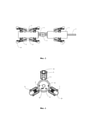
В устройстве для мониторинга систем электрического обогрева трубопроводов, состоящем из отдельных корпусов, соединенных между собой гермокабелем, технический результат достигается тем, что корпуса модуля сбора информации и модуля передачи данных выполнены в форме цилиндра, в передней и задней части которых на боковых стенках жестко закреплены выступы, крышки с выполненными пазами, которые установлены с двух сторон каждого из корпусов, в нижней части корпусов жестко закреплены опоры, на которых с возможностью съема установлены подвижные крепления для опорных колес, при этом они развернуты на 120° относительно друг друга, амортизаторы жестко закреплены на корпусе и соединены через подвижную платформу с возможностью перемещения вверх и низ с подвижным креплением, привод установлен внутри корпуса и соединен через питающие кабели с креплением к монорельсу, внутри подвижного крепления установлена зубчато-ременная передача, которая состоит из большого шкива, который соединен с приводом, а малый шкив - с опорным колесом, в верхней части корпусов жестко закреплены опоры, на которых с возможностью съема установлены крепления к монорельсу, в верхней части которого закреплен токоприемник, в крышке, которая установлена в передней части корпуса модуля сбора информации выполнены отверстия в центре для установки фронтальной видеокамеры, а ниже отверстия меньшего диаметра для установки температурного датчика и полупроводниковых диодов, модули передачи данных и сбора информации соединены между собой шарниром, внутри модуля сбора информации установлены фронтальная видеокамера, в которую встроены полупроводниковые диоды и датчик температуры, которые, соединены через гермокабели с блоком связи, внутри модуля передачи данных установлены приводы и блок связи, приводы, фронтальная видеокамера и блок связи соединены через питающие кабели с токоприемником.In a device for monitoring electric heating systems for pipelines, consisting of separate housings interconnected by a pressure cable, the technical result is achieved by the fact that the housings of the information collection module and the data transmission module are made in the form of a cylinder, in the front and rear parts of which protrusions are rigidly fixed on the side walls , covers with grooves, which are installed on both sides of each of the housings, supports are rigidly fixed in the lower part of the housings, on which movable fasteners for the support wheels are installed with the possibility of removal, while they are turned 120 ° relative to each other, the shock absorbers are rigidly fixed to housing and connected through a movable platform with the ability to move up and down with a movable mount, the drive is installed inside the hull and connected via power cables to the monorail mount, a toothed belt drive is installed inside the movable mount, which consists of a large pulley, which is connected to the drive, a small the first pulley - with a support wheel, supports are rigidly fixed in the upper part of the housings, on which fastenings to the monorail are installed with the possibility of removal, in the upper part of which the pantograph is fixed, in the cover, which is installed in the front part of the housing of the information collection module, holes are made in the center for installation front video camera, and below the hole of a smaller diameter for installing a temperature sensor and semiconductor diodes, the data transmission and information collection modules are interconnected by a hinge; a communication unit, drives and a communication unit are installed inside the data transmission module, drives, a front video camera and a communication unit are connected via power cables to the current collector.
Устройство поясняется следующей фигурой:The device is illustrated by the following figure:
фиг. 1 - общий вид устройства;fig. 1 - general view of the device;
фиг. 2 - вид с боку;fig. 2 - side view;
фиг. 3 - вид снизу;fig. 3 - bottom view;
фиг. 4 - вид спереди;fig. 4 - front view;
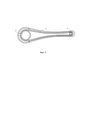
фиг. 5 - зубчато-ременный механизм;fig. 5 - toothed belt mechanism;
1 - монорельс;1 - monorail;
2 - модуль сбора информации;2 - information collection module;
3 - модуль передачи данных;3 - data transmission module;
4 - шарнир;4 - hinge;
5 - гермокабель;5 - pressure cable;
6 - подвижные крепления;6 - movable mounts;
7 - амортизаторы;7 - shock absorbers;
8 - фронтальная видеокамера;8 - front video camera;
9 - крепление к монорельсу;9 - fastening to the monorail;
10 - полупроводниковые диоды10 - semiconductor diodes
11 - датчик температуры;11 - temperature sensor;
12 - токоприемник;12 - current collector;
13 - приводы;13 - drives;
14 - блок связи;14 - communication unit;
15 - пазы;15 - grooves;
16 - крышки;16 - covers;
17 - опоры;17 - supports;
18 - питающие кабели;18 - power cables;
19 - опорные колеса;19 - support wheels;
20 - большой шкив;20 - large pulley;
21 - малый шкив;21 - small pulley;
22 - зубчатый ремень;22 - toothed belt;
23 - подвижная платформа.23 - mobile platform.
Устройство для мониторинга систем электрического обогрева трубопроводов включает модуль сбора информации 2 (фиг. 1-5) и модуль передачи данных 3. Корпус модуля сбора информации 2 и модуля передачи данных 3, выполнены в форме цилиндра в передней и задней части на боковых стенках жестко закреплены выступы. Крышки 16 с выполненными пазами 15, которые установлены с двух сторон каждого из корпусов. В нижней части корпуса модуля сбора информации 2 и модуля передачи данных 3, жестко закреплены опоры 17, на них с возможностью съема установлены подвижные крепления 6 для опорных колес 19. Подвижные крепления 6 развернуты на 120° относительно друг друга. Расположение в 120° друг от друга обусловлено тем, что устройство обладает тремя точками опоры, которые должны быть равномерно распределены по поверхности цилиндра. При 120° износ колес и креплений минимален. Также при меньшем угле между колесами уменьшается устойчивость на поворотах, а при большем угле уменьшается стабильность при движении и увеличивается износ подвижного крепления 9 к монорельсу 1. На корпусе жестко закреплены амортизаторы 7 соединенные через подвижную платформу 23 с возможностью перемещения вверх и низ с подвижным креплением 6 для обеспечения возможности упора колес в стенки трубопровода. Привод 13 установлен внутри корпуса и соединен через питающие кабели 18 с креплением к монорельсу 9. Внутри подвижного крепления 6 находится зубчато-ременная передача, которая состоит из большого шкива 20, малого шкива 21 и зубчатого ремня 22. Большой шкив 20 соединен с приводом 13, а малый шкив 21 - с опорным колесом 19. В верхней части корпуса модуля сбора информации 2 и модуля передачи данных 3 жестко закреплены опоры 17, на них с возможностью съема установлены крепления к монорельсу 9. В верхней части крепления к монорельсу 9 установлен токоприемник 12. В передней части корпуса модуля сбора информации 2 в крышке выполнены отверстия в центре для установки фронтальной видеокамеры 8, а ниже отверстия меньшего диаметра для установки температурного датчика 11 и полупроводниковых диодов 10 для освещения.The device for monitoring electric heating systems for pipelines includes an information collection module 2 (Fig. 1-5) and a data transmission module 3. The body of the
Внутри модуля сбора информации 2 установлены два привода 13 и фронтальная видеокамера 8, в которую встроены полупроводниковые диоды 10 и датчик температуры 11. Фронтальная видеокамера 8 соединена через гермокабели 5 с блоком связи 14. Датчик температуры 11 соединен через гермокабели 5 с блоком связи 14.Inside the
Внутри модуля передачи данных 3 установлены четыре привода и блок связи 14. Приводы 13, фронтальная видеокамера 8 и блок связи 14 соединены через питающие кабели 18.Four drives and a
Модуль передачи данных 3 соединен с модулем сбора информации 2 при помощи шарнира 4, который обеспечивает подвижность блоков относительно друг друга.The data transmission module 3 is connected to the
Мониторинг осуществляется следующим образом. Устройство устанавливают внутри трубопровода СКИН-системы, на монорельс 1 и его соединяют с помощью крепление к монорельсу 9, которые обеспечивает устойчивое положение робота при движении внутри трубопровода. На монорельс 1 подается ток, токоприемник 12 соприкасается с монорельсом, в результате чего электрическая энергия от рельса передается на приводы 13 через питающие кабели 18. Привод 13 приводит в движение большой шкив 20, который вращает с помощью зубчатого ремня 22 малый шкив 21, а тот в свою очередь приводит в движение опорное колесо 19, в результате чего устройство перемещается по монорельсу 1 внутри трубопровода за счет креплений 9, жестко присоединенных к опорам 17 на корпусах блока сбора информации 2 и блока передачи данных 3. Подвижные крепления 6 опорных колес обеспечивают прохождение искривленных участков трассы за счет амортизаторов 7, соединенных с подвижным креплением 6 через подвижную платформу 23, позволяющую перемещаться вверх и вниз. Прохождение кривых поворота и участков сложной конфигурации достигается за счет шарнира 4, соединяющего модуль сбора информации 2 и модуль передачи информации 3, и гибкого гермокабеля 5. В процессе движения по трассе трубопровода видеофиксация внутренней поверхности с интеллектуальным распознаванием дефектов осуществляется фронтальной видеокамерой 8 с полупроводниковыми диодами 10, освещающими внутреннюю полость трубопровода. По ходу трассы датчик температуры 11 фиксирует температуру внутри СКИН-трубы, информация сохраняется на накопителе и в дальнейшем анализируется в ходе камеральной обработки. Участки с пониженной температурой свидетельствуют о нарушении герметичности конструкции теплоизоляции или о ее повышенной влажности.Monitoring is carried out as follows. The device is installed inside the pipeline of the SKIN system, on the
Устройство обладает рядом преимуществ перед предшествующими моделями. Данное робототехническое устройство позволяет наблюдать за системами электрического нагрева даже в искривленных участках трубопроводов в силу своей конструкции. Также фронтальная камера позволяет наблюдать за большой площадью, так как она находится в передней части устройств, и ее угол обзора ничем не ограничен. Робот не имеет ограничений по времени использования, так как питается напрямую и не зависит от аккумуляторов. Также он имеет высокую скорость прохождения трубы благодаря жестким креплениям к монорельсу и опорным колесам с надежными упорами к внутренним стенкам трубопровода.The device has a number of advantages over previous models. This robotic device makes it possible to observe electric heating systems even in curved sections of pipelines due to its design. Also, the front camera allows you to observe a large area, since it is located in front of the devices, and its viewing angle is not limited in any way. The robot has no restrictions on the time of use, as it is powered directly and does not depend on batteries. It also has a high speed of pipe passage due to rigid attachments to the monorail and supporting wheels with reliable stops against the inner walls of the pipeline.
Claims (1)
Priority Applications (1)
| Application Number | Priority Date | Filing Date | Title |
|---|---|---|---|
| RU2021121099A RU2766373C1 (en) | 2021-07-16 | 2021-07-16 | Pipeline electric heating system monitoring device |
Applications Claiming Priority (1)
| Application Number | Priority Date | Filing Date | Title |
|---|---|---|---|
| RU2021121099A RU2766373C1 (en) | 2021-07-16 | 2021-07-16 | Pipeline electric heating system monitoring device |
Publications (1)
| Publication Number | Publication Date |
|---|---|
| RU2766373C1 true RU2766373C1 (en) | 2022-03-15 |
Family
ID=80736585
Family Applications (1)
| Application Number | Title | Priority Date | Filing Date |
|---|---|---|---|
| RU2021121099A RU2766373C1 (en) | 2021-07-16 | 2021-07-16 | Pipeline electric heating system monitoring device |
Country Status (1)
| Country | Link |
|---|---|
| RU (1) | RU2766373C1 (en) |
Citations (5)
| Publication number | Priority date | Publication date | Assignee | Title |
|---|---|---|---|---|
| FR2638813A1 (en) * | 1988-11-09 | 1990-05-11 | Nancy Ecole Sup Sciences Techn | Self-propelled vehicle for grinding piping |
| RU2969U1 (en) * | 1995-01-19 | 1996-10-16 | Акционерное общество закрытого типа "Робоцентр" | IN-TRAFFIC VEHICLE |
| RU2111453C1 (en) * | 1993-09-02 | 1998-05-20 | Центральный научно-исследовательский институт "Гидроприбор" | Multi-purpose diagnostic tool-flaw detector for checking pipeline for conditions |
| RU2418234C1 (en) * | 2009-11-06 | 2011-05-10 | Дочернее открытое акционерное общество "Оргэнергогаз" | In-pipe transport facility |
| RU2451867C2 (en) * | 2010-06-17 | 2012-05-27 | Открытое акционерное общество "Газпром" | In-tube control apparatus and method for moving it in gas main with preset uniform velocity |
-
2021
- 2021-07-16 RU RU2021121099A patent/RU2766373C1/en active
Patent Citations (5)
| Publication number | Priority date | Publication date | Assignee | Title |
|---|---|---|---|---|
| FR2638813A1 (en) * | 1988-11-09 | 1990-05-11 | Nancy Ecole Sup Sciences Techn | Self-propelled vehicle for grinding piping |
| RU2111453C1 (en) * | 1993-09-02 | 1998-05-20 | Центральный научно-исследовательский институт "Гидроприбор" | Multi-purpose diagnostic tool-flaw detector for checking pipeline for conditions |
| RU2969U1 (en) * | 1995-01-19 | 1996-10-16 | Акционерное общество закрытого типа "Робоцентр" | IN-TRAFFIC VEHICLE |
| RU2418234C1 (en) * | 2009-11-06 | 2011-05-10 | Дочернее открытое акционерное общество "Оргэнергогаз" | In-pipe transport facility |
| RU2451867C2 (en) * | 2010-06-17 | 2012-05-27 | Открытое акционерное общество "Газпром" | In-tube control apparatus and method for moving it in gas main with preset uniform velocity |
Similar Documents
| Publication | Publication Date | Title |
|---|---|---|
| US7210364B2 (en) | Autonomous robotic crawler for in-pipe inspection | |
| US7182025B2 (en) | Autonomous robotic crawler for in-pipe inspection | |
| EP1373783B1 (en) | Gas main robotic inspection system | |
| CN112828856B (en) | A new type of multifunctional combined inspection robot for tunnels | |
| CN114517710B (en) | Hanging rail type inspection robot system applied to mine | |
| CN103867848A (en) | Spiral driving pipeline robot | |
| CN111043448A (en) | Pipeline robot | |
| KR102353477B1 (en) | Rail robot and rail robot system | |
| KR102458696B1 (en) | Rail robot and rail robot system | |
| CN211694003U (en) | A detection and control system of a pipeline robot | |
| RU2766373C1 (en) | Pipeline electric heating system monitoring device | |
| CN118493361A (en) | Multi-joint bionic composite snake-shaped robot | |
| CN205632714U (en) | Wheeled magnetism adsorbs wall climbing robot | |
| CN102554915A (en) | Robot for taking out foreign matters from ventilation duct of air conditioner of train | |
| JPH0370669B2 (en) | ||
| CN114184238A (en) | Old pipeline inspection robot based on telescopic wheel train | |
| RU2600043C2 (en) | Robot ball | |
| CN117704197B (en) | Pipeline robot | |
| CN209495071U (en) | A magnetically adsorbed traveling soft robot for maintenance of submarine oil pipelines | |
| CN110937088A (en) | Dual-drive AUV magnetic coupling vector propulsion device suitable for ice hole arrangement | |
| CN211694004U (en) | A detachable wheel replacement assembly and a pipeline robot having the same | |
| CN211875101U (en) | Waterproof sealing structure and pipeline robot with same | |
| CN212195684U (en) | spherical robot | |
| CN211764756U (en) | Amphibious scientific investigation robot | |
| CN114593306A (en) | Pipe diameter adaptive wheeled module and pipeline robot |