RU2763368C1 - Production equipment of a section of the rolling mill with rotary grips and hot rolling production line - Google Patents
Production equipment of a section of the rolling mill with rotary grips and hot rolling production line Download PDFInfo
- Publication number
- RU2763368C1 RU2763368C1 RU2020137206A RU2020137206A RU2763368C1 RU 2763368 C1 RU2763368 C1 RU 2763368C1 RU 2020137206 A RU2020137206 A RU 2020137206A RU 2020137206 A RU2020137206 A RU 2020137206A RU 2763368 C1 RU2763368 C1 RU 2763368C1
- Authority
- RU
- Russia
- Prior art keywords
- rotary
- roller table
- rolling mill
- section
- production equipment
- Prior art date
Links
- 238000005096 rolling process Methods 0.000 title claims abstract description 132
- 238000004519 manufacturing process Methods 0.000 title claims abstract description 81
- 238000005098 hot rolling Methods 0.000 title claims description 15
- 230000033001 locomotion Effects 0.000 claims description 20
- 238000009434 installation Methods 0.000 claims description 8
- 230000003993 interaction Effects 0.000 claims description 2
- 230000000694 effects Effects 0.000 abstract description 2
- 238000007493 shaping process Methods 0.000 abstract 1
- 239000000126 substance Substances 0.000 abstract 1
- 238000000034 method Methods 0.000 description 8
- 230000000712 assembly Effects 0.000 description 6
- 238000000429 assembly Methods 0.000 description 6
- 230000033764 rhythmic process Effects 0.000 description 4
- 238000007789 sealing Methods 0.000 description 3
- 238000010276 construction Methods 0.000 description 2
- 230000008878 coupling Effects 0.000 description 2
- 238000010168 coupling process Methods 0.000 description 2
- 238000005859 coupling reaction Methods 0.000 description 2
- 230000006872 improvement Effects 0.000 description 2
- 229910000831 Steel Inorganic materials 0.000 description 1
- 230000005540 biological transmission Effects 0.000 description 1
- 238000009826 distribution Methods 0.000 description 1
- 238000005516 engineering process Methods 0.000 description 1
- 239000000463 material Substances 0.000 description 1
- 230000004048 modification Effects 0.000 description 1
- 238000012986 modification Methods 0.000 description 1
- 230000008569 process Effects 0.000 description 1
- 230000009467 reduction Effects 0.000 description 1
- 230000004044 response Effects 0.000 description 1
- 239000010959 steel Substances 0.000 description 1
Images


Classifications
-
- B—PERFORMING OPERATIONS; TRANSPORTING
- B21—MECHANICAL METAL-WORKING WITHOUT ESSENTIALLY REMOVING MATERIAL; PUNCHING METAL
- B21B—ROLLING OF METAL
- B21B39/00—Arrangements for moving, supporting, or positioning work, or controlling its movement, combined with or arranged in, or specially adapted for use in connection with, metal-rolling mills
- B21B39/14—Guiding, positioning or aligning work
- B21B39/16—Guiding, positioning or aligning work immediately before entering or after leaving the pass
-
- B—PERFORMING OPERATIONS; TRANSPORTING
- B21—MECHANICAL METAL-WORKING WITHOUT ESSENTIALLY REMOVING MATERIAL; PUNCHING METAL
- B21B—ROLLING OF METAL
- B21B37/00—Control devices or methods specially adapted for metal-rolling mills or the work produced thereby
- B21B37/68—Camber or steering control for strip, sheets or plates, e.g. preventing meandering
-
- B—PERFORMING OPERATIONS; TRANSPORTING
- B21—MECHANICAL METAL-WORKING WITHOUT ESSENTIALLY REMOVING MATERIAL; PUNCHING METAL
- B21B—ROLLING OF METAL
- B21B39/00—Arrangements for moving, supporting, or positioning work, or controlling its movement, combined with or arranged in, or specially adapted for use in connection with, metal-rolling mills
- B21B39/008—Rollers for roller conveyors
-
- B—PERFORMING OPERATIONS; TRANSPORTING
- B21—MECHANICAL METAL-WORKING WITHOUT ESSENTIALLY REMOVING MATERIAL; PUNCHING METAL
- B21B—ROLLING OF METAL
- B21B39/00—Arrangements for moving, supporting, or positioning work, or controlling its movement, combined with or arranged in, or specially adapted for use in connection with, metal-rolling mills
- B21B39/20—Revolving, turning-over, or like manipulation of work, e.g. revolving in trio stands
- B21B39/24—Revolving, turning-over, or like manipulation of work, e.g. revolving in trio stands by tongs or grippers
-
- B—PERFORMING OPERATIONS; TRANSPORTING
- B65—CONVEYING; PACKING; STORING; HANDLING THIN OR FILAMENTARY MATERIAL
- B65G—TRANSPORT OR STORAGE DEVICES, e.g. CONVEYORS FOR LOADING OR TIPPING, SHOP CONVEYOR SYSTEMS OR PNEUMATIC TUBE CONVEYORS
- B65G47/00—Article or material-handling devices associated with conveyors; Methods employing such devices
- B65G47/22—Devices influencing the relative position or the attitude of articles during transit by conveyors
- B65G47/24—Devices influencing the relative position or the attitude of articles during transit by conveyors orientating the articles
- B65G47/244—Devices influencing the relative position or the attitude of articles during transit by conveyors orientating the articles by turning them about an axis substantially perpendicular to the conveying plane
-
- B—PERFORMING OPERATIONS; TRANSPORTING
- B65—CONVEYING; PACKING; STORING; HANDLING THIN OR FILAMENTARY MATERIAL
- B65G—TRANSPORT OR STORAGE DEVICES, e.g. CONVEYORS FOR LOADING OR TIPPING, SHOP CONVEYOR SYSTEMS OR PNEUMATIC TUBE CONVEYORS
- B65G47/00—Article or material-handling devices associated with conveyors; Methods employing such devices
- B65G47/74—Feeding, transfer, or discharging devices of particular kinds or types
- B65G47/90—Devices for picking-up and depositing articles or materials
-
- B—PERFORMING OPERATIONS; TRANSPORTING
- B21—MECHANICAL METAL-WORKING WITHOUT ESSENTIALLY REMOVING MATERIAL; PUNCHING METAL
- B21B—ROLLING OF METAL
- B21B1/00—Metal-rolling methods or mills for making semi-finished products of solid or profiled cross-section; Sequence of operations in milling trains; Layout of rolling-mill plant, e.g. grouping of stands; Succession of passes or of sectional pass alternations
- B21B1/02—Metal-rolling methods or mills for making semi-finished products of solid or profiled cross-section; Sequence of operations in milling trains; Layout of rolling-mill plant, e.g. grouping of stands; Succession of passes or of sectional pass alternations for rolling heavy work, e.g. ingots, slabs, blooms, or billets, in which the cross-sectional form is unimportant ; Rolling combined with forging or pressing
- B21B1/06—Metal-rolling methods or mills for making semi-finished products of solid or profiled cross-section; Sequence of operations in milling trains; Layout of rolling-mill plant, e.g. grouping of stands; Succession of passes or of sectional pass alternations for rolling heavy work, e.g. ingots, slabs, blooms, or billets, in which the cross-sectional form is unimportant ; Rolling combined with forging or pressing in a non-continuous process, e.g. triplet mill, reversing mill
-
- B—PERFORMING OPERATIONS; TRANSPORTING
- B21—MECHANICAL METAL-WORKING WITHOUT ESSENTIALLY REMOVING MATERIAL; PUNCHING METAL
- B21B—ROLLING OF METAL
- B21B1/00—Metal-rolling methods or mills for making semi-finished products of solid or profiled cross-section; Sequence of operations in milling trains; Layout of rolling-mill plant, e.g. grouping of stands; Succession of passes or of sectional pass alternations
- B21B1/02—Metal-rolling methods or mills for making semi-finished products of solid or profiled cross-section; Sequence of operations in milling trains; Layout of rolling-mill plant, e.g. grouping of stands; Succession of passes or of sectional pass alternations for rolling heavy work, e.g. ingots, slabs, blooms, or billets, in which the cross-sectional form is unimportant ; Rolling combined with forging or pressing
- B21B2001/028—Slabs
-
- B—PERFORMING OPERATIONS; TRANSPORTING
- B21—MECHANICAL METAL-WORKING WITHOUT ESSENTIALLY REMOVING MATERIAL; PUNCHING METAL
- B21B—ROLLING OF METAL
- B21B2201/00—Special rolling modes
- B21B2201/06—Thermomechanical rolling
-
- B—PERFORMING OPERATIONS; TRANSPORTING
- B21—MECHANICAL METAL-WORKING WITHOUT ESSENTIALLY REMOVING MATERIAL; PUNCHING METAL
- B21B—ROLLING OF METAL
- B21B2273/00—Path parameters
- B21B2273/22—Aligning on rolling axis, e.g. of roll calibers
-
- B—PERFORMING OPERATIONS; TRANSPORTING
- B21—MECHANICAL METAL-WORKING WITHOUT ESSENTIALLY REMOVING MATERIAL; PUNCHING METAL
- B21B—ROLLING OF METAL
- B21B39/00—Arrangements for moving, supporting, or positioning work, or controlling its movement, combined with or arranged in, or specially adapted for use in connection with, metal-rolling mills
- B21B39/02—Feeding or supporting work; Braking or tensioning arrangements, e.g. threading arrangements
- B21B39/04—Lifting or lowering work for conveying purposes, e.g. tilting tables arranged immediately in front of or behind the pass
-
- B—PERFORMING OPERATIONS; TRANSPORTING
- B21—MECHANICAL METAL-WORKING WITHOUT ESSENTIALLY REMOVING MATERIAL; PUNCHING METAL
- B21B—ROLLING OF METAL
- B21B39/00—Arrangements for moving, supporting, or positioning work, or controlling its movement, combined with or arranged in, or specially adapted for use in connection with, metal-rolling mills
- B21B39/02—Feeding or supporting work; Braking or tensioning arrangements, e.g. threading arrangements
- B21B39/12—Arrangement or installation of roller tables in relation to a roll stand
Abstract
Description
ОБЛАСТЬ ТЕХНИКИFIELD OF TECHNOLOGY
[0001] Настоящее изобретение относится к области техники, касающейся стана горячей прокатки, а в частности, к производственному оборудованию участка прокатного стана с поворотными захватами и производственной линии горячей прокатки.[0001] The present invention relates to the technical field of a hot rolling mill, and in particular to the production equipment of a swivel mill section and a hot rolling production line.
УРОВЕНЬ ТЕХНИКИBACKGROUND OF THE INVENTION
[0002] В последние годы с быстрым усовершенствованием производственных мощностей по производству средних и толстых листов в Китае производство средних и толстых листов значительно увеличилось, а конкуренция на рынке стала более жесткой. Расширение диапазона рабочих характеристик прокатываемых слябов, повышение производительности и увеличение выхода стальных листов стали основными задачами и трудностями в этой области.[0002] In recent years, with the rapid improvement of the production capacity of medium and thick sheets in China, the production of medium and thick sheets has increased significantly, and competition in the market has become more intense. Expanding the performance range of rolled slabs, increasing productivity and increasing the yield of steel sheets have become major challenges and challenges in this field.
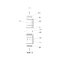
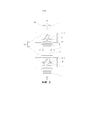
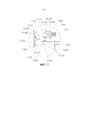
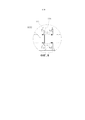
[0003] В настоящее время, как изображено на ФИГ. 1 и 2, обычная производственная линия на участке прокатного стана содержит последовательно расположенные транспортировочный роликовый стол 901 на входной стороне, поворотный роликовый стол 902 на входной стороне, подающий ролик 904 на входной стороне, прокатный ролик 905, подающий ролик 906 на выходной стороне, поворотный роликовый стол 907 на выходной стороне и транспортировочный роликовый стол 909 на выходной стороне от начала производственной цепочки к ее концу. Направляющие на входной стороне соответственно расположены с обеих сторон поворотного роликового стола 902 на входной стороне, а впускные нажимные пластины 903 расположены на направляющих на входной стороне. Направляющие на выходной стороне соответственно расположены с обеих сторон поворотного роликового стола 907 на выходной стороне, а выпускные нажимные пластины 908 расположены на направляющих на выходной стороне. Во время прокатки средних и толстых листов прокатываемое изделие 910 регулируют поворотным роликовым столом 902 на входной стороне на заданный угол и затем после регулировки угла прокатывают в прямом направлении прокатным роликом 905; после прокатки в прямом направлении прокатываемое изделие 910 снова регулируют поворотным роликовым столом 907 на выходной стороне на заданный угол и затем после регулировки угла прокатывают в обратном направлении прокатным роликом 905. Прокатываемое изделие 910 может быть прямо выведено или подвергнуто последующей обычной продольной прокатке после многократных прокаток в прямом и обратном направлениях под углом согласно требованиям к производственному процессу.[0003] Currently, as shown in FIG. 1 and 2, a typical production line in a rolling mill section comprises in series a transport roller table 901 on the input side, a rotary roller table 902 on the input side, a
[0004] Однако в существующей обычной производственной линии заданный угол прокатываемого изделия 910 регулируют за счет взаимодействия с боковой направляющей, расположенной с обеих сторон производственной линии, скорость реагирования является низкой, а время для регулировки заданного угла прокатываемого изделия 910 является продолжительным, что не способствует повышению эффективности производства. Кроме того, угол регулировки прокатываемого изделия 910 боковой направляющей обычно является горизонтальным или продольным, и при этом угол регулировки существенно ограничен.[0004] However, in the existing conventional production line, the predetermined angle of the rolled
[0005] Пока не предложено эффективного решения проблем низкой скорости и низкой точности при регулировке заданного угла прокатываемого изделия прокатным станом в предшествующем уровне техники.[0005] So far, there has been no effective solution to the problems of low speed and low accuracy in adjusting the predetermined angle of a rolled product by a rolling mill in the prior art.
[0006] Таким образом, основываясь на многолетнем опыте и в соответствующих отраслях промышленности, изобретателями по настоящей заявки предложены производственное оборудование участка прокатного стана с поворотными захватами и производственная линия горячей прокатки, с тем чтобы преодолеть недостатки предшествующего уровня техники.[0006] Thus, based on many years of experience and related industries, the inventors of the present application propose the production equipment of a rolling mill section with rotary jaws and a hot rolling production line in order to overcome the shortcomings of the prior art.
РАСКРЫТИЕ СУЩНОСТИ ИЗОБРЕТЕНИЯDISCLOSURE OF THE INVENTION
[0007] Задачей настоящего раскрытия является обеспечение производственного оборудования участка прокатного стана с поворотными захватами и производственной линии горячей прокатки. Угол прокатываемого изделия регулируют поворотным захватом, расположенным на поворотном роликовом столе на входной стороне и поворотном роликовом столе на выходной стороне, с тем чтобы оптимизировать скорость и улучшить точность, а также сократить время регулировки угла прокатываемого изделия, достичь высокой степени автоматизации и уменьшить сложность работы, что способствует улучшению производственного ритма и эффективности производства.[0007] It is an object of the present disclosure to provide manufacturing equipment for a swivel mill section and a hot rolling production line. The angle of the rolled product is adjusted by the rotary gripper located on the rotary table on the input side and the rotary table on the output side, so as to optimize the speed and improve the accuracy, and shorten the time of adjusting the angle of the rolled product, achieve a high degree of automation and reduce the complexity of operation, which contributes to the improvement of the production rhythm and production efficiency.
[0008] Задача настоящего раскрытия может быть решена посредством принятия следующих технических решений.[0008] the Problem of the present disclosure can be solved by adopting the following technical solutions.
[0009] В настоящем раскрытии обеспечено производственное оборудование участка прокатного стана с поворотными захватами, содержащее поворотно-захватное устройство, выполненное с возможностью подъема и поворота, и поворотный роликовый стол, причем поворотно-захватное устройство расположено соответственно выше поворотного роликового стола и выполнено с возможностью соответственно зажатия прокатываемого изделия, проходящего через поворотный роликовый стол, и приведения в движение прокатываемого изделия с его подъемом и поворотом, так что осевая линия прокатываемого изделия и осевая линия прокатки образуют заданный угол.[0009] In the present disclosure, there is provided manufacturing equipment for a rolling mill section with rotary grippers, comprising a rotary gripper capable of being lifted and rotated and a rotary roller table, wherein the rotary gripper is located respectively above the rotary roller table and configured to respectively clamping the rolled product passing through the rotary roller table, and driving the rolled product to rise and turn, so that the centerline of the rolled product and the centerline of rolling form a predetermined angle.
[0010] В предпочтительном варианте реализации настоящего раскрытия поворотный роликовый стол содержит поворотный роликовый стол на входной стороне и поворотный роликовый стол на выходной стороне. Имеется по меньшей мере две группы поворотно-захватных устройств, причем указанные две группы поворотно-захватных устройств соответственно расположены на поворотном роликовом столе на входной стороне и выше поворотного роликового стола на выходной стороне, и между поворотным роликовым столом на входной стороне и поворотным роликовым столом на выходной стороне расположен прокатный ролик.[0010] In a preferred embodiment of the present disclosure, the rotary roller table comprises a rotary roller table on the input side and a rotary roller table on the output side. There are at least two groups of rotary grippers, said two groups of rotary grippers being respectively located on the rotary roller table on the input side and above the rotary roller table on the output side, and between the rotary roller table on the input side and the rotary roller table on the the output side is a rolling roller.
[0011] В предпочтительном варианте реализации настоящего раскрытия поворотно-захватное устройство содержит монтажную раму, подъемный узел, поворотный узел и по меньшей мере два зажимных узла, причем монтажная рама установлена с фиксацией выше поворотного роликового стола, подъемный узел расположен на верхней части монтажной рамы, поворотный узел расположен в нижней части подъемного узла, и каждый из зажимных узлов расположен вдоль направления длины поворотного роликового стола; каждый зажимной узел содержит два зажимных органа, выполненных с возможностью перемещения в противоположных направлениях, при этом каждый из зажимных органов расположен с возможностью перемещения в нижней части соответствующего траверсного узла, и два траверсных узла находятся на одной и той же горизонтальной прямой линии, так что обеспечена возможность перемещения двух зажимных органов в каждой группе в противоположных направлениях по одной и той же горизонтальной прямой линии, а каждый из траверсных узлов расположен в нижней части поворотного узла.[0011] In a preferred embodiment of the present disclosure, the swivel gripper includes a mounting frame, a lifting assembly, a swivel assembly, and at least two clamping assemblies, wherein the mounting frame is fixedly mounted above the rotary roller table, the lifting assembly is located on top of the mounting frame, the rotary unit is located at the bottom of the lifting unit, and each of the clamping units is located along the length direction of the rotary roller table; each clamping assembly comprises two clamping members movable in opposite directions, each of the clamping members being movable at the bottom of the respective traverse assembly, and the two traverse assemblies are on the same horizontal straight line, so that the possibility of moving two clamping bodies in each group in opposite directions along the same horizontal straight line, and each of the traverse nodes is located in the lower part of the rotary node.
[0012] В предпочтительном варианте реализации настоящего раскрытия монтажная рама содержит соединительный держатель и две прямостоящие стойки, причем две прямостоящие стойки расположены соответственно с обеих сторон поворотного роликового стола, нижний конец каждой из двух прямостоящих стоек закреплен на установочной плите, верхние концы двух прямостоящих стоек соединены с двумя концами соединительного держателя, а подъемный узел расположен на соединительном держателе.[0012] In a preferred embodiment of the present disclosure, the mounting frame comprises a connecting holder and two upright posts, the two upright posts respectively located on both sides of the turntable, the lower end of each of the two upright posts is fixed to the mounting plate, the upper ends of the two upright posts are connected with two ends of the connecting holder, and the lifting unit is located on the connecting holder.
[0013] В предпочтительном варианте реализации настоящего раскрытия подъемный узел содержит подъемный цилиндр, при этом закрепленный конец подъемного цилиндра установлен на верхней части соединительного держателя, и шток поршня подъемного цилиндра проходит через соединительный держатель в вертикальном направлении и соединен с верхней частью поворотного узла.[0013] In a preferred embodiment of the present disclosure, the lift assembly includes a lift cylinder, wherein the fixed end of the lift cylinder is mounted on the top of the connecting holder, and the piston rod of the lift cylinder passes through the connecting holder in a vertical direction and is connected to the top of the rotary assembly.
[0014] В предпочтительном варианте реализации настоящего раскрытия подъемный узел дополнительно содержит два стержня для направления подъема и две втулки для направления подъема. Указанные две втулки для направления подъема соответственно расположены на соединительном держателе и размещены соответственно с обеих сторон подъемного цилиндра. Стержни для направления подъема расположены с возможностью скольжения в соответствующих втулках для направления подъема, и нижние концы стержней для направления подъема проходят через соответствующие втулки для направления подъема и соединены с верхней частью поворотного узла.[0014] In a preferred embodiment of the present disclosure, the lift assembly further comprises two lift guide rods and two lift guide bushings. Said two sleeves for the lifting direction are respectively located on the connecting holder and placed respectively on both sides of the lifting cylinder. The up direction rods are slidably disposed in respective up direction bushings, and the lower ends of the up direction rods pass through the respective up direction bushes and are connected to the upper part of the swivel assembly.
[0015] В предпочтительном варианте реализации настоящего раскрытия поворотный узел содержит соединительную пластину и первый корпус, причем первый корпус расположен в нижней части соединительной пластины, и между первым корпусом и соединительной пластиной образована вмещающая полость. Первый приводной вал, выполненный с возможностью вращения, расположен в вертикальном направлении во вмещающей полости, и верхний конец первого приводного вала соединен с выходным валом первого приводного двигателя, и на первый приводной вал надето с фиксацией первое приводное зубчатое колесо. Первый ведомый вал, параллельный первому приводному валу, расположен с фиксацией во вмещающей полости. Снаружи первого ведомого вала надет с возможностью поворота вращательный каркас, имеющий цилиндрическую форму. На вращательный каркас надето с фиксацией первое ведомое зубчатое колесо, причем первое ведомое зубчатое колесо зацеплено с первым приводным зубчатым колесом, а нижняя часть вращательного каркаса соединена с траверсными узлами.[0015] In a preferred embodiment of the present disclosure, the rotary assembly includes a connection plate and a first housing, the first housing being located at the bottom of the connection plate, and a containing cavity is formed between the first housing and the connection plate. The first rotatable drive shaft is located in the vertical direction in the containing cavity, and the upper end of the first drive shaft is connected to the output shaft of the first drive motor, and the first drive gear is put on the first drive shaft with fixation. The first driven shaft, parallel to the first drive shaft, is located with fixation in the containing cavity. Outside the first driven shaft, a rotational frame having a cylindrical shape is put on with the possibility of rotation. The first driven gear is put on the rotational frame with fixation, the first driven gear is engaged with the first drive gear, and the lower part of the rotational frame is connected to the traverse units.
[0016] В предпочтительном варианте реализации настоящего раскрытия на верхней части соединительной пластины расположена опора первого двигателя, на опоре первого двигателя установлен первый приводной двигатель, с первым приводным двигателем соединен первый кодовый датчик положения, и между выходным валом первого приводного двигателя и первым приводным валом расположена первая муфта.[0016] In a preferred embodiment of the present disclosure, a first motor mount is located on the top of the connection plate, a first drive motor is mounted on the first motor mount, a first encoder is connected to the first drive motor, and a first clutch.
[0017] В предпочтительном варианте реализации настоящего раскрытия в нижней части поворотного узла расположена монтажная рама, и каждый из траверсных узлов закреплен на монтажной раме.[0017] In a preferred embodiment of the present disclosure, a mounting frame is located at the bottom of the pivot assembly, and each of the traverse assemblies is secured to the mounting frame.
[0018] Траверсный узел содержит часть для направления перемещения, второй приводной двигатель, второй корпус и опору подшипника. Часть для направления перемещения, второй корпус и опора подшипника расположены на верхней части монтажной рамы. Второй приводной вал, выполненный с возможностью вращения, расположен во втором корпусе вдоль горизонтального направления. Один конец второго приводного вала соединен с выходным валом второго приводного двигателя, и на второй приводной вал надето с фиксацией второе приводное зубчатое колесо. Во втором корпусе расположен второй ведомый вал, параллельный второму приводному валу. На второй ведомый вал надето с фиксацией второе ведомое зубчатое колесо, причем второе ведомое зубчатое колесо зацеплено со вторым приводным зубчатым колесом. Один конец второго ведомого вала соединен с одним концом части для направления перемещения через вторую муфту, а другой конец части для направления перемещения расположен с возможностью поворота на опоре подшипника через промежуточный подшипник. Верхняя часть зажимного органа расположена с возможностью перемещения на части для направления перемещения.[0018] The traverse assembly includes a travel direction portion, a second drive motor, a second housing, and a bearing support. The travel direction part, the second housing and the bearing support are located on the top of the mounting frame. The second rotatable drive shaft is located in the second housing along the horizontal direction. One end of the second drive shaft is connected to the output shaft of the second drive motor, and the second drive gear is latched onto the second drive shaft. In the second housing there is a second driven shaft parallel to the second drive shaft. The second driven gear is put on the second driven shaft with fixation, and the second driven gear is engaged with the second drive gear. One end of the second driven shaft is connected to one end of the movement direction part through the second clutch, and the other end of the movement direction part is rotatably located on the bearing support through the intermediate bearing. The upper part of the clamping body is located with the possibility of movement on the part for the direction of movement.
[0019] В предпочтительном варианте реализации настоящего раскрытия часть для направления перемещения представляет собой винтовую конструкцию или шарико-винтовую пару с надетой гайкой.[0019] In a preferred embodiment of the present disclosure, the movement direction portion is a screw structure or a ball screw with a nut.
[0020] В предпочтительном варианте реализации настоящего раскрытия на внешней части второго корпуса расположена опора второго двигателя, на опоре второго двигателя установлен второй приводной двигатель, со вторым приводным двигателем соединен второй кодовый датчик положения, и между выходным валом второго приводного двигателя и вторым приводным валом расположена третья муфта.[0020] In a preferred embodiment of the present disclosure, a second motor support is located on the outside of the second housing, a second drive motor is mounted on the second engine support, a second encoder is connected to the second drive motor, and a second encoder is located between the output shaft of the second drive motor and the second drive shaft. third clutch.
[0021] В предпочтительном варианте реализации настоящего раскрытия в нижней части монтажной рамы вдоль направления длины поворотного роликового стола расположены множество рельсовых направляющих. С обеих сторон верхней части зажимного органа соответственно установлены ролики. Верхние части зажимных органов соединены с возможностью взаимодействия с соответствующими рельсовыми направляющими через ролики.[0021] In a preferred embodiment of the present disclosure, a plurality of guide rails are disposed at the bottom of the mounting frame along the length direction of the turntable roller table. On both sides of the upper part of the clamping body, rollers are installed respectively. The upper parts of the clamping bodies are connected with the possibility of interaction with the corresponding rail guides through the rollers.
[0022] В предпочтительном варианте реализации настоящего раскрытия зажимной орган представляет собой длинную узкую конструкцию, расположенную в вертикальном направлении. В нижней части и на внешней стенке расположен выступ, предотвращающий скольжение, зажимного органа, обращенный к стороне прокатываемого изделия.[0022] In a preferred embodiment of the present disclosure, the clamping member is a long, narrow structure arranged in a vertical direction. In the lower part and on the outer wall there is a protrusion that prevents slipping of the clamping body, facing the side of the rolled product.
[0023] В предпочтительном варианте реализации настоящего раскрытия поворотный роликовый стол на входной стороне и поворотный роликовый стол на выходной стороне образованы множеством первых роликовых столов, расположенных сторона к стороне в горизонтальном направлении, причем первые роликовые столы соединены соответственно с двигателями первых роликовых столов, и соседние двигатели первых роликовых столов выполнены с возможностью приведения в движение соответствующих первых роликовых столов с их поворотом в одном и том же направлении или в противоположных направлениях.[0023] In a preferred embodiment of the present disclosure, the input side turntable and the output side turntable are formed by a plurality of first roller tables arranged side by side in a horizontal direction, the first roller tables being connected respectively to the motors of the first roller tables, and adjacent the motors of the first roller tables are configured to drive the respective first roller tables to rotate in the same direction or in opposite directions.
[0024] В предпочтительном варианте реализации настоящего раскрытия между выпускным концом поворотного роликового стола на входной стороне и прокатным роликом расположен впускной клетьевой ролик, а между прокатным роликом и впускным концом поворотного роликового стола на выходной стороне расположен выпускной клетьевой ролик.[0024] In the preferred embodiment of the present disclosure, an inlet cage roller is located between the outlet end of the turntable on the input side and the rolling roller, and an outlet roller is located between the rolling roller and the inlet end of the rotary roller table on the output side.
[0025] В предпочтительном варианте реализации настоящего раскрытия впускной клетьевой ролик и выпускной клетьевой ролик образованы множеством вторых роликовых столов, расположенных сторона к стороне в горизонтальном направлении, и одна сторона каждого из вторых роликовых столов обеспечена двигателем второго роликового стола, посредством которого обеспечено приведение в действие второго роликового стола с его поворотом.[0025] In a preferred embodiment of the present disclosure, the inlet cage roller and the outlet cage roller are formed by a plurality of second roller tables arranged side by side in a horizontal direction, and one side of each of the second roller tables is provided with a second roller table motor, through which the actuation is provided. second roller table with its rotation.
[0026] В предпочтительном варианте реализации настоящего раскрытия производственное оборудование участка прокатного стана с поворотными захватами дополнительно содержит транспортировочный роликовый стол на входной стороне и выпускной транспортировочный роликовый стол. Выпускной конец транспортировочного роликового стола на входной стороне соединен с впускным концом поворотного роликового стола на входной стороне, а впускной конец транспортировочного роликового стола на выходной стороне соединен с выпускным концом поворотного роликового стола на выходной стороне.[0026] In a preferred embodiment of the present disclosure, the production equipment of the rotary jaw rolling mill section further comprises a transport roller table on the inlet side and an exit transport roller table. The output end of the transport roller table on the input side is connected to the input end of the rotary roller table on the input side, and the input end of the transport roller table on the output side is connected to the output end of the rotary roller table on the output side.
[0027] В предпочтительном варианте реализации настоящего раскрытия транспортировочный роликовый стол на входной стороне и транспортировочный роликовый стол на выходной стороне образованы множеством третьих роликовых столов, расположенных сторона к стороне в горизонтальном направлении, и одна сторона каждого из третьих роликовых столов обеспечена двигателем третьего роликового стола, посредством которого обеспечено приведение в действие третьего роликового стола для поворота.[0027] In the preferred embodiment of the present disclosure, the transport roller table on the input side and the transport roller table on the output side are formed by a plurality of third roller tables arranged side by side in the horizontal direction, and one side of each of the third roller tables is provided with a motor of the third roller table, by means of which actuation of the third roller table for rotation is ensured.
[0028] Настоящее раскрытие обеспечивает производственную линию горячей прокатки, содержащую участок установки прокатного стана, причем участок установки прокатного стана обеспечен производственным оборудованием участка прокатного стана с поворотными захватами, как описано выше.[0028] The present disclosure provides a hot rolling production line comprising a rolling mill station, the rolling mill station being provided with rotary gripper mill station manufacturing equipment as described above.
[0029] В предпочтительном варианте реализации настоящего раскрытия участок установки прокатного стана является участком одноклетевого прокатного стана, причем участок одноклетевого прокатного стана обеспечен производственным оборудованием участка прокатного стана с поворотными захватами.[0029] In a preferred embodiment of the present disclosure, the rolling mill section is a single-stand rolling mill section, wherein the single-stand rolling mill section is provided with mill section manufacturing equipment with rotary grips.
[0030] В предпочтительном варианте реализации настоящего раскрытия участок установки прокатного стана содержит участок прокатного стана для черновой прокатки и участок прокатного стана для чистовой прокатки, причем выпускной конец участка прокатного стана для черновой прокатки соединен с впускным концом участка прокатного стана для чистовой прокатки, и производственное оборудование участка прокатного стана с поворотными захватами расположено на участке прокатного стана для черновой прокатки и/или участке прокатного стана для чистовой прокатки.[0030] In a preferred embodiment of the present disclosure, the rolling mill section comprises a rough rolling mill section and a finish rolling mill section, wherein an outlet end of the rough rolling mill section is connected to an inlet end of the fine rolling mill section, and the production the rolling mill section equipment is located in the rough rolling mill section and/or the fine rolling mill section.
[0031] В виду вышеизложенного характеристиками и преимуществами производственного оборудования участка прокатного стана с поворотными захватами и производственной линии горячей прокатки согласно настоящему раскрытию являются: поворотно-захватное устройство, выполненное с возможностью выполнения подъемных и поворотных действий, расположено на поворотном роликовом столе производственной линии горячей прокатки; когда прокатываемое изделие проходит через поворотный роликовый стол, поворотно-захватное устройство может зажимать прокатываемое изделие и приводить в движение прокатываемое изделие с его подъемом и поворотом, таким образом заданный угол прокатываемого изделия во время процесса прокатки может быть отрегулирован быстро и точно, что отвечает требованиям к установочному направлению прокатываемого изделия и сокращает время регулировки угла прокатываемого изделия. В дополнение к этому, нет необходимости вручную регулировать высоту подъема и угол поворота прокатываемого изделия, что повышает степень автоматизации, уменьшает сложность работы и значительно улучшает производственный ритм и эффективность производства.[0031] In view of the foregoing, the characteristics and advantages of the production equipment of the rotary grip rolling mill section and the hot rolling production line according to the present disclosure are: ; when the rolled product passes through the rotary roller table, the rotary gripper can clamp the rolled product and drive the rolled product to lift and turn, so that the predetermined angle of the rolled product during the rolling process can be adjusted quickly and accurately, which meets the requirements for installation direction of the rolled product and shortens the time for adjusting the angle of the rolled product. In addition, there is no need to manually adjust the lifting height and rotation angle of the rolled product, which increases the degree of automation, reduces the complexity of work, and greatly improves the production rhythm and production efficiency.
КРАТКОЕ ОПИСАНИЕ ЧЕРТЕЖЕЙBRIEF DESCRIPTION OF THE DRAWINGS
[0032] Следующие чертежи предназначены только для схематического иллюстрирования и объяснения настоящего раскрытия, а не для ограничения объема настоящего раскрытия. На чертежах:[0032] The following drawings are only intended to schematically illustrate and explain the present disclosure, and not to limit the scope of the present disclosure. On the drawings:
[0033] на ФИГ. 1 схематически представлена конструкция производственной линии с прокатным станом в предшествующем уровне техники для продольной прокатки прокатываемого изделия;[0033] in FIG. 1 is a schematic representation of the construction of a production line with a rolling mill in the prior art for longitudinal rolling of a rolled product;
[0034] на ФИГ. 2 схематически представлена конструкция производственной линии с прокатным станом в предшествующем уровне техники для горизонтальной прокатки прокатываемого изделия;[0034] in FIG. 2 is a schematic representation of a production line structure with a prior art rolling mill for horizontal rolling of a rolled product;
[0035] на ФИГ. 3 схематически представлена конструкция производственного оборудования участка прокатного стана с поворотными захватами согласно настоящему раскрытию;[0035] in FIG. 3 is a schematic representation of the construction of the production equipment of a rolling mill section with rotary jaws according to the present disclosure;
[0036] на ФИГ. 4 представлен вид спереди поворотно-захватного устройства производственного оборудования участка прокатного стана с поворотными захватами согласно настоящему раскрытию;[0036] in FIG. 4 is a front view of a rotary gripper of a production facility of a rolling mill section with rotary grippers according to the present disclosure;
[0037] на ФИГ. 5 представлен вид спереди в разрезе поворотно-захватного устройства производственного оборудования участка прокатного стана с поворотными захватами согласно настоящему раскрытию;[0037] in FIG. 5 is a sectional front view of a rotary gripper production equipment of a rolling mill section with rotary grippers according to the present disclosure;
[0038] на ФИГ. 6 представлен вид спереди в разрезе поворотного узла поворотно-захватного устройства производственного оборудования участка прокатного стана с поворотными захватами согласно настоящему раскрытию;[0038] in FIG. 6 is a front sectional view of a swivel assembly of a swivel-gripper production equipment of a rolling mill section with swivel grips according to the present disclosure;
[0039] на ФИГ. 7 представлен вид спереди в разрезе траверсного узла поворотно-захватного устройства производственного оборудования участка прокатного стана с поворотными захватами согласно настоящему раскрытию;[0039] in FIG. 7 is a front sectional view of a traverse assembly of a rotary gripper production equipment of a rolling mill section with rotary grippers according to the present disclosure;
[0040] на ФИГ. 8 схематически представлена конструкция соединения части для направления перемещения и опоры подшипника в траверсном узле поворотно-захватного устройства производственного оборудования участка прокатного стана с поворотными захватами; и[0040] in FIG. 8 schematically shows the design of the connection of the part for the direction of movement and the bearing support in the traverse assembly of the rotary gripper of the production equipment of the rolling mill section with rotary grippers; and
[0041] на ФИГ. 9 представлен вид с левого бока поворотно-захватного устройства производственного оборудования участка прокатного стана с поворотными захватами согласно настоящему раскрытию.[0041] in FIG. 9 is a left side view of a rotary gripper of the production equipment of a rolling mill section with rotary grippers according to the present disclosure.
[0042] Ссылочные обозначения для известного технического решения:[0042] Reference symbols for the known technical solution:
[0043] 901: впускной транспортировочный роликовый стол;[0043] 901: inlet transport roller table;
902: поворотный роликовый стол на входной стороне;902: rotary roller table on the input side;
903: впускная нажимная пластина;903: inlet pressure plate;
904: впускной клетьевой ролик;904: inlet cage roller;
905: прокатный ролик;905: rolling roller;
906: выпускной клетьевой ролик;906: outlet cage roller;
907: поворотный роликовый стол на выходной стороне;907: rotary roller table on the output side;
908: выпускная нажимная пластина;908: exhaust pressure plate;
909: выпускной транспортировочный роликовый стол;909: discharge transport roller table;
910: прокатываемое изделие.910: rolled product.
[0044] Ссылочные обозначения для настоящего раскрытия:[0044] Reference symbols for this disclosure:
[0045] 1: поворотный роликовый стол на входной стороне;[0045] 1: rotary roller table on the input side;
2: прокатный ролик;2: rolling roller;
3: поворотный роликовый стол на выходной стороне;3: rotary roller table on the output side;
4: впускной транспортировочный роликовый стол;4: inlet transport roller table;
5: впускной клетьевой ролик;5: inlet cage roller;
6: выпускной клетьевой ролик;6: outlet cage roller;
7: выпускной транспортировочный роликовый стол;7: discharge transport roller table;
8: впускная боковая направляющая;8: inlet side rail;
811: впускная нажимная пластина;811: inlet pressure plate;
9: выпускная боковая направляющая;9: outlet side rail;
911: выпускная нажимная пластина;911: exhaust pressure plate;
10: прокатываемое изделие;10: rolled product;
11: поворотно-захватное устройство;11: rotary gripper;
111: подъемный узел;111: lifting unit;
1111: подъемный цилиндр;1111: lift cylinder;
1112: стержень для направления подъема;1112: rod for lifting direction;
1113: втулка для направления подъема;1113: sleeve for lifting direction;
112: монтажная рама;112: mounting frame;
1121: соединительный держатель;1121: connecting holder;
1122: прямостоящая стойка;1122: upright post;
113: траверсный узел;113: traverse assembly;
1131: монтажная рама;1131: mounting frame;
11311: рельсовая направляющая;11311: rail guide;
1132: часть для направления перемещения;1132: part for the direction of movement;
11321: вторая муфта;11321: second clutch;
1133: второй корпус;1133: second building;
11331: опора второго двигателя;11331: support for the second engine;
1134: второй приводной вал;1134: second drive shaft;
11341: пятая концевая крышка;11341: fifth end cap;
11342: шестая концевая крышка;11342: sixth end cap;
11343: третий упорный подшипник;11343: third thrust bearing;
11344: третий самоустанавливающийся подшипник;11344: third self-aligning bearing;
1135: второй ведомый вал;1135: second driven shaft;
11351: седьмая концевая крышка;11351: seventh end cap;
11352: восьмая концевая крышка;11352: eighth end cap;
11353: четвертый упорный подшипник;11353: fourth thrust bearing;
11354: четвертый самоустанавливающийся подшипник;11354: fourth self-aligning bearing;
1136: второе приводное зубчатое колесо;1136: second drive gear;
1137: второе ведомое зубчатое колесо;1137: second driven gear;
1138: второй приводной двигатель;1138: second drive motor;
11381: третья муфта;11381: third clutch;
1139: второй кодовый датчик положения;1139: second encoder;
114: поворотный узел;114: swivel assembly;
1140: вращательный каркас;1140: rotating frame;
1141: соединительная пластина;1141: connecting plate;
1142: первый корпус;1142: first building;
1143: первый приводной вал;1143: first drive shaft;
11431: первая концевая крышка;11431: first end cap;
11432: вторая концевая крышка;11432: second end cap;
11433: первый упорный подшипник;11433: first thrust bearing;
11434: первый самоустанавливающийся подшипник;11434: the first self-aligning bearing;
1144: первый ведомый вал;1144: first driven shaft;
11441: третья концевая крышка;11441: third end cap;
11442: четвертая концевая крышка;11442: fourth end cap;
11443: второй упорный подшипник;11443: second thrust bearing;
11444: второй самоустанавливающийся подшипник;11444: second self-aligning bearing;
1145: первое приводное зубчатое колесо;1145: first drive gear;
1146: первое ведомое зубчатое колесо;1146: first driven gear;
1147: первый приводной двигатель;1147: first drive motor;
11471: опора первого двигателя;11471: support of the first engine;
1148: первый кодовый датчик положения;1148: first encoder;
1149: первая муфта;1149: first clutch;
115: зажимной орган;115: clamping body;
1151: выступ, предотвращающий скольжение;1151: anti-slip ridge;
1152: ролик;1152: roller;
116: опора подшипника;116: bearing support;
117: промежуточный подшипник;117: intermediate bearing;
12: поворотный роликовый стол.12: rotary roller table.
ОСУЩЕСТВЛЕНИЕ ИЗОБРЕТЕНИЯIMPLEMENTATION OF THE INVENTION
[0046] Чтобы иметь более ясное представление о технических признаках, объектах и обеспечиваемых результатах настоящего раскрытия, далее будут описаны конкретные варианты реализации настоящего раскрытия со ссылкой на чертежи.[0046] In order to have a clearer understanding of the technical features, objects, and provided results of the present disclosure, specific embodiments of the present disclosure will now be described with reference to the drawings.
[0047] Первый вариант реализации[0047] First Embodiment
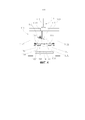
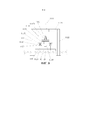
[0048] Как показано на ФИГ. 3, в настоящем раскрытии обеспечено производственное оборудование участка прокатного стана с поворотными захватами, содержащее поворотно-захватное устройство 11, выполненное с возможностью подъема и поворота, и поворотный роликовый стол 12, причем поворотно-захватное устройство 11 расположено соответственно выше поворотного роликового стола 12 и выполнено с возможностью соответственно зажатия прокатываемого изделия 10, проходящего через поворотный роликовый стол 12, и приведения в движение прокатываемого изделия 10 с его подъемом и поворотом, так что осевая линия прокатываемого изделия 10 и осевая линия прокатки образуют заданный угол. В настоящем раскрытии поворотно-захватное устройство 11 расположено выше поворотного роликового стола 12, поворотно-захватное устройство 11 может зажимать прокатываемое изделие 10 и приводит в движение прокатываемое изделие 10 с его подъемом и поворотом, таким образом заданный угол прокатываемого изделия 10 во время процесса прокатки может быть отрегулирован быстро и точно, что отвечает требованиям к установочному направлению прокатываемого изделия 10 и сокращает время регулировки угла прокатываемого изделия 10; в дополнение к этому, нет необходимости вручную регулировать высоту подъема и угол поворота прокатываемого изделия 10, что повышает степень автоматизации, уменьшает сложность работы и значительно улучшает производственный ритм и эффективность производства.[0048] As shown in FIG. 3, in the present disclosure, there is provided a rolling mill section manufacturing facility with rotary grippers, comprising a
[0049] Производственное оборудование участка прокатного стана с поворотными захватами также содержит обычные устройства, такие как множество транспортировочных роликовых столов, боковые направляющие, клетьевые ролики и прокатные станы, для взаимодействия с поворотно-захватным устройством 11 и поворотным роликовым столом 12 для завершения прокатки прокатываемого изделия 10.[0049] The production equipment of the rotary gripper section of the rolling mill also includes conventional devices such as a plurality of transport roller tables, side guides, stand rollers, and rolling mills for cooperating with the
[0050] В применяемом при необходимости варианте реализации настоящего раскрытия, как показано на ФИГ. 3, поворотный роликовый стол 12 содержит поворотный роликовый стол 1 на входной стороне и поворотный роликовый стол 3 на выходной стороне. Имеется по меньшей мере две группы поворотно-захватных устройств 11, причем две группы поворотно-захватных устройств 11 соответственно расположены на поворотном роликовом столе 1 на входной стороне и выше поворотного роликового стола 3 на выходной стороне, и между поворотным роликовым столом 1 на входной стороне и поворотным роликовым столом 3 на выходной стороне расположен прокатный ролик 2. Поворотно-захватные устройства 11 соответственно зажимают прокатываемые изделия 10, проходящие через поворотный роликовый стол 1 на входной стороне и поворотный роликовый стол 3 на выходной стороне, и приводят в движение прокатываемые изделия 10 с выполнением их подъема и поворотного перемещения. Поворотно-захватное устройство 11, выполненное с возможностью приведения в движение прокатываемого изделия 10 с его подъемом и поворотом, расположено выше каждого поворотного роликового стола 1 на входной стороне и поворотного роликового стола 3 на выходной стороне производственной линии горячей прокатки. Когда прокатываемое изделие 10 проходит через поворотный роликовый стол 1 на входной стороне и поворотный роликовый стол 3 на выходной стороне, заданный угол прокатываемого изделия 10 может быть предварительно откалиброван посредством поворотно-захватного устройства 11, что улучшает точность заданного угла, образованного осевой линией прокатываемого изделия 10 и осевой линией прокатки.[0050] In an optionally applicable embodiment of the present disclosure, as shown in FIG. 3, the rotary roller table 12 includes a rotary roller table 1 on the input side and a rotary roller table 3 on the output side. There are at least two groups of
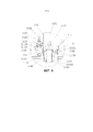
[0051] В применяемом при необходимости варианте реализации настоящего раскрытия, как показано на ФИГ. 4, поворотно-захватное устройство 11 содержит монтажную раму 112, подъемный узел 111, поворотный узел 114 и по меньшей мере два зажимных узла. Монтажная рама 112 установлена с фиксацией выше поворотного роликового стола 12, подъемный узел 111 расположен на верхней части монтажной рамы 112, поворотный узел 114 расположен в нижней части подъемного узла 111, и каждый из зажимных узлов расположен вдоль направления длины поворотного роликового стола 12. Высоту зажимного узла регулируют подъемным узлом 111, так что зажимной узел может быть выровнен с прокатываемым изделием 10, и множество групп зажимных узлов взаимодействуют друг с другом со стабильным зажатием прокатываемого изделия 10, при этом угол прокатываемого изделия 10 регулируют поворотным узлом 114. Каждый зажимной узел содержит два зажимных органа 115, выполненных с возможностью перемещения в противоположных направлениях, при этом каждый из зажимных органов 115 расположен с возможностью перемещения в нижней части соответствующего траверсного узла 113, и два траверсных узла 113 находятся на одной и той же горизонтальной прямой линии, так что обеспечена возможность перемещения двух зажимных органов 115 в каждой группе в противоположных направлениях по одной и той же горизонтальной прямой линии, и каждый из траверсных узлов 113 расположен в нижней части поворотного узла 114. В каждом зажимном узле два зажимных органа 115 взаимодействуют друг с другом и упираются в две противоположные внешние стенки прокатываемого изделия 10, тем самым зажимая прокатываемое изделие 10.[0051] In an optionally applicable embodiment of the present disclosure, as shown in FIG. 4, the
[0052] В частности, как показано на ФИГ. 4, 5 и 9, монтажная рама 112 содержит соединительный держатель 1121 и две прямостоящие стойки 1122. Соединительный держатель 1121 представляет собой длинную конструкцию в форме стержня, расположенную в горизонтальном направлении. Обе прямостоящие стойки 1122 расположены вертикально по отношению к соединительному держателю 1121. Две прямостоящие стойки 1122 соответственно расположены с обеих сторон поворотного роликового стола 12. Нижние концы двух прямостоящих стоек 1122 закреплены на установочной плите. Верхний конец одной прямостоящей стойки 1122 соединен с одним концом соединительного держателя 1121, а другой конец другой прямостоящей стойки 1122 соединен с другим концом соединительного держателя 1121. Подъемный узел 111 расположен на соединительном держателе 1121. Зажимной узел расположен выше прокатываемого изделия 10 посредством монтажной рамы 112 так, чтобы соответствовать требованиям к зажиму для прокатываемого изделия 10.[0052] In particular, as shown in FIG. 4, 5, and 9, the mounting
[0053] В частности, как показано на ФИГ. 4 и 5, подъемный узел 111 содержит подъемный цилиндр 1111, два стержня 1112 для направления подъема и две втулки 1113 для направления подъема. Закрепленный конец подъемного цилиндра 1111 установлен в верхнем среднем положении соединительного держателя 1121. Шток поршня подъемного цилиндра 1111 проходит вниз в вертикальном направлении, проходит через соединительный держатель 1121 и затем соединяется с верхней частью поворотного узла 114. Две втулки 1113 для направления подъема соответственно расположены с фиксацией на соединительном держателе 1121 и соответственно размещены с обеих сторон подъемного цилиндра 1111. Два стержня 1112 для направления подъема расположены в соответствующих втулках 1113 для направления подъема с возможностью скольжения вверх и вниз, и оба нижних конца двух стержней 1112 для направления подъема проходят через соответствующие втулки 1113 для направления подъема и соединены с верхней частью поворотного узла 114. Подъемный цилиндр 1111 служит для регулировки подъема зажимного узла. Два стержня 1112 для направления подъема служат для позиционирования подъемного цилиндра 1111, предотвращая поворот штока поршня подъемного цилиндра 1111 во время процесса подъема и улучшая устойчивость подъемного цилиндра 1111 при его перемещении вверх и вниз.[0053] In particular, as shown in FIG. 4 and 5, the
[0054] Кроме того, подъемный цилиндр 1111 может быть, но без ограничения, гидравлическим цилиндром.[0054] In addition, the
[0055] В частности, как показано на ФИГ. 4-6, поворотный узел 114 содержит соединительную пластину 1141 и первый корпус 1142. Соединительная пластина 1141 расположена в горизонтальном направлении, а шток поршня подъемного цилиндра 1111 и два стержня 1112 для направления подъема соединены с фиксацией с соединительной пластиной 1141. Первый корпус 1142 расположен в нижней части соединительной пластины 1141, и между первым корпусом 1142 и соединительной пластиной 1141 образована вмещающая полость. Первый приводной двигатель 1147 расположен на верхней части соединительной пластины 1141. Первый приводной вал 1143, выполненный с возможностью вращения, расположен во вмещающей полости вдоль вертикального направления. Верхний конец первого приводного вала 1143 соединен с выходным валом первого приводного двигателя 1147. На среднюю часть первого приводного вала 1143 надето с фиксацией первое приводное зубчатое колесо 1145. Первый ведомый вал 1144, параллельный первому приводному валу 1143, расположен с фиксацией во вмещающей полости. Снаружи первого ведомого вала 1144 надет с возможностью поворота вращательный каркас 1140, имеющий цилиндрическую форму. На среднюю часть вращательного каркаса 1140 надето с фиксацией первое ведомое зубчатое колесо 1146, причем первое ведомое зубчатое колесо 1146 зацеплено с первым приводным зубчатым колесом 1145. Нижняя часть вращательного каркаса 1140 проходит к внешней части вмещающей полости и соединена с каждым траверсным узлом 113. Первый приводной двигатель 1147 приводит в движение первый приводной вал 1143 с его поворотом. Первое приводное зубчатое колесо 1145 и первое ведомое зубчатое колесо 1146 зацеплены друг с другом для приведения в движение вращательного каркаса 1140 с его поворотом, затем посредством этого приводятся в движение траверсные узлы 113 с их поворотом так, чтобы иметь возможность регулировать направление зажимного узла, расположенного в нижней части траверсного узла 113, с регулировкой угла прокатываемого изделия 10 на поворотном роликовом столе 12.[0055] In particular, as shown in FIG. 4-6, the
[0056] Кроме того, как показано на ФИГ. 6, на верхней части соединительной пластины 1141 расположена с фиксацией опора 11471 первого двигателя. На опоре 11471 первого двигателя установлен первый приводной двигатель 1147. Первый приводной двигатель 1147 соединен с первым кодовым датчиком 1148 положения. Между выходным валом первого приводного двигателя 1147 и первым приводным валом 1143 расположена первая муфта 1149. Посредством первого кодового датчика 1148 положения могут быть записаны в реальном времени скорость поворота и направление поворота первого приводного вала 1143, так что может быть получена информация об угле поворота прокатываемого изделия 10.[0056] In addition, as shown in FIG. 6, on the top of the connecting
[0057] Кроме того, как показано на ФИГ. 6, между верхним концом первого приводного вала 1143 и внутренней стенкой вмещающей полости расположен первый упорный подшипник 11433, а между нижним концом первого приводного вала 1143 и внутренней стенкой вмещающей полости расположен первый самоустанавливающийся подшипник 11434. Между верхним концом первого ведомого вала 1144 и вращательным каркасом 1140 расположен второй упорный подшипник 11443, а между нижним концом первого ведомого вала 1144 и вращательным каркасом 1140 расположен второй самоустанавливающийся подшипник 11444. Улучшается стабильность поворота поворотного узла 114.[0057] In addition, as shown in FIG. 6, between the upper end of the
[0058] Кроме того, как показано на ФИГ. 6, верхний конец первого приводного вала 1143 обеспечен первой концевой крышкой 11431. Нижний конец первого приводного вала 1143 обеспечен второй концевой крышкой 11432, а между первой концевой крышкой 11431 со второй концевой крышкой 11432 и внутренней стенкой вмещающей полости расположено уплотнительное кольцо. Верхний конец первого ведомого вала 1144 обеспечен третьей концевой крышкой 11441, нижний конец первого ведомого вала 1144 обеспечен четвертой концевой крышкой 11442, а между третьей концевой крышкой 11441 с четвертой концевой крышкой 11442 и вращательным каркасом 1140 расположено уплотнительное кольцо. Таким образом, обеспечена герметичная рабочая среда для первого приводного вала 1142 и первого ведомого вала 1144.[0058] In addition, as shown in FIG. 6, the upper end of the
[0059] Кроме того, два стержня 1112 для направления подъема могут быть соединены с фиксацией с верхней частью соединительной пластины 1141 в любом положении при условии, что это не влияет на поворот поворотного узла 114.[0059] In addition, the two
[0060] В частности, как показано на ФИГ. 4-9, в нижней части поворотного узла 114 расположена монтажная рама 1131. Монтажная рама 1131 является прямоугольной блочной конструкцией, расположенной в горизонтальном направлении, и все траверсные узлы 113 закреплены на монтажной раме 1131. При этом траверсный узел 113 содержит часть 1132 для направления перемещения, второй приводной двигатель 1138, второй корпус 1133 и опору 116 подшипника. Часть 1132 для направления перемещения, второй корпус 1133 и опора 116 подшипника расположены на верхней части монтажной рамы 1131. Второй приводной вал 1134, выполненный с возможностью вращения, расположен во втором корпусе 1133 вдоль горизонтального направления. Один конец второго приводного вала 1134 соединен с выходным валом второго приводного двигателя 1138. На среднюю часть второго приводного вала 1134 надето с фиксацией второе приводное зубчатое колесо 1136. Во втором корпусе 1133 расположен второй ведомый вал 1135, выполненный с возможностью вращения. Второй ведомый вал 1135 параллелен второму приводному валу 1134. На второй ведомый вал 1135 надето с фиксацией второе ведомое зубчатое колесо 1137, причем второе ведомое зубчатое колесо 1137 зацеплено со вторым приводным зубчатым колесом 1136. Один конец второго ведомого вала 1135 соединен с одним концом части 1132 для направления перемещения второй муфтой 11321, а другой конец части 1132 для направления перемещения расположен с возможностью поворота на опоре 116 подшипника через промежуточный подшипник 117. Верхняя часть зажимного органа 115 расположена с возможностью перемещения на части 1132 для направления перемещения. Второй приводной двигатель 1138 приводит в движение второй приводной вал 1134 с его поворотом. Второе приводное зубчатое колесо 1136 и второе ведомое зубчатое колесо 1137, которые зацеплены для приведения в движение части 1132 для направления перемещения с ее поворотом, для регулировки положения зажимного органа 115 в горизонтальном направлении, тем самым обеспечивая, что два зажимных органа 115 взаимодействуют друг с другом со стабильным зажатием прокатываемого изделия 10.[0060] In particular, as shown in FIG. 4-9, a mounting
[0061] Кроме того, часть 1132 для направления перемещения может, но не ограничиваясь этим, представлять собой винтовую конструкцию или шарико-винтовую пару с надетой гайкой.[0061] In addition, the
[0062] Кроме того, как показано на ФИГ. 7, на внешней части второго корпуса 1133 расположена с фиксацией опора 11331 второго двигателя. На опоре 11331 второго двигателя установлен второй приводной двигатель 1138. Со вторым кодовым датчиком 1139 положения соединен второй приводной двигатель 1138. Между выходным валом второго приводного двигателя 1138 и вторым приводным валом 1134 расположена третья муфта 11381. Скорость поворота и направление поворота части 1132 для направления перемещения могут быть записаны в реальном времени вторым кодовым датчиком 1139 положения, с тем чтобы получать информацию о положении зажимного органа 115 в горизонтальном направлении.[0062] In addition, as shown in FIG. 7, on the outside of the
[0063] Кроме того, как показано на ФИГ. 7, между одним концом второго приводного вала 1134, который находится возле второго приводного двигателя 1138, и внутренней стенкой второго корпуса 1133 расположен третий упорный подшипник 11343, а между одним концом второго приводного вала 1134, который находится на удалении от второго приводного двигателя 1138, и внутренней стенкой второго корпуса 1133 расположен третий самоустанавливающийся подшипник 11344. Между одним концом второго ведомого вала 1135, который находится возле части 1132 для направления перемещения, и внутренней стенкой второго корпуса 1133 расположен четвертый упорный подшипник 11353, а между одним концом второго ведомого вала 1135, который находится на удалении от части 1132 для направления перемещения, и внутренней стенкой второго корпуса 1133 расположен четвертый самоустанавливающийся подшипник 11354.[0063] In addition, as shown in FIG. 7, between one end of the
[0064] Кроме того, как показано на ФИГ. 7, один конец второго приводного вала 1134 обеспечен пятой концевой крышкой 11341, другой конец второго приводного вала 1134 обеспечен шестой концевой крышкой 11342, а между пятой концевой крышкой 11341 с шестой концевой крышкой 11342 и внутренней стенкой второго корпуса 1133 расположено уплотнительное кольцо. Один конец второго ведомого вала 1135 обеспечен седьмой концевой крышкой 11351, а другой конец второго ведомого вала 1135 обеспечен восьмой концевой крышкой 11352, а между седьмой концевой крышкой 11351 и восьмой концевой крышкой 11352 со вторым корпусом 1133 расположено уплотнительное кольцо. Таким образом, обеспечена герметичная рабочая среда для второго приводного вала 1134 и второго ведомого вала 1135.[0064] In addition, as shown in FIG. 7, one end of the
[0065] В частности, как показано на ФИГ. 4 и 9, вдоль направления длины поворотного роликового стола 12 в нижней части монтажной рамы 1131 расположены множество рельсовых направляющих 11311. С обеих сторон верхней части зажимного органа 115 соответственно установлены ролики 1152 посредством штифтов. Верхние части зажимных органов 115 расположены в соответствующих рельсовых направляющих 11311, и ролик 1152 соединен с возможностью взаимодействия с внутренними стенками двух противоположных сторон соответствующих рельсовых направляющих 11311. Рельсовые направляющие 11311 обеспечивают возможность плавного перемещения зажимного органа 115 вдоль части 1132 для направления перемещения.[0065] In particular, as shown in FIG. 4 and 9, along the length direction of the turntable roller table 12, a plurality of
[0066] Кроме того, как показано на ФИГ. 4, 5 и 9, зажимной орган 115 представляет собой длинную узкую конструкцию, расположенную в вертикальном направлении. В нижней части и на внешней стенке расположен выступ 1151, предотвращающий скольжение, зажимного органа 115, обращенный к стороне прокатываемого изделия 10. При этом для выступа 1151, предотвращающего скольжение, можно выбирать различные материалы в зависимости от веса прокатываемого изделия 10, так что между зажимным органом 115 и прокатываемым изделием 10 создаются разные силы трения, что может обеспечить стабильный зажимающий эффект прокатываемого изделия 10.[0066] In addition, as shown in FIG. 4, 5 and 9, the clamping
[0067] В применяемом при необходимости варианте реализации настоящего раскрытия, как изображено на ФИГ. 3, поворотный роликовый стол 1 на входной стороне и поворотный роликовый стол 3 на выходной стороне образованы множеством первых роликовых столов, расположенных сторона к стороне в горизонтальном направлении, при этом каждый из первых роликовых столов соединен с двигателем первого роликового стола, и соседние двигатели первых роликовых столов выполнены с возможностью приведения в движение соответствующих первых роликовых столов с их поворотом в одном и том же направлении или в противоположных направлениях. Посредством управления направлением поворота и скоростью поворота каждого из первых роликовых столов можно обеспечить плавный поворот прокатываемого изделия 10 на заданный угол.[0067] In an optionally applicable embodiment of the present disclosure, as shown in FIG. 3, the turntable roller table 1 on the input side and the turntable roller table 3 on the output side are formed by a plurality of first roller tables arranged side by side in the horizontal direction, each of the first roller tables is connected to the motor of the first roller table, and the adjacent motors of the first roller tables The tables are configured to drive the respective first roller tables to rotate in the same direction or in opposite directions. By controlling the rotation direction and rotation speed of each of the first roller tables, the rolled
[0068] Кроме того, когда направления поворота соседних первых роликовых столов на поворотном роликовом столе 1 на входной стороне и поворотном роликовом столе 3 на выходной стороне противоположны друг другу, причем первые роликовые столы могут быть сгруппированы по нечетным и четным числам, причем первые роликовые столы в одной и той же нечетной или четной группе поворачиваются в одном и том же направлении, при этом первые роликовые столы в нечетной группе и первые роликовые столы в четной группе поворачиваются в противоположных направлениях (т.е. два соседних первых роликовых стола поворачиваются в противоположных направлениях, а два первых роликовых стола с одним первым роликовым столом между ними поворачиваются в одном и том же направлении).[0068] In addition, when the rotation directions of adjacent first roller tables on the input side rotary roller table 1 and the output side rotary roller table 3 are opposite to each other, the first roller tables may be grouped in odd and even numbers, the first roller tables in the same odd or even group turn in the same direction, with the first roller tables in the odd group and the first roller tables in the even group turning in opposite directions (i.e. two adjacent first roller tables turn in opposite directions , and the first two roller tables with one first roller table between them turn in the same direction).
[0069] В частности, двигатели первых роликовых столов могут быть расположены на одной и той же стороне или с обеих сторон поворотного роликового стола 1 на входной стороне и поворотного роликового стола 3 на выходной стороне при условии, что это удобно для управления поворотным роликовым столом 1 на входной стороне и поворотным роликовым столом 3 на выходной стороне. Когда необходимо управлять поворотом первых роликовых столов в одном и том же направлении в поворотном роликовом столе 1 на входной стороне и поворотном роликовом столе 3 на выходной стороне, с каждым из двигателей первых роликовых столов может быть соединена распределительная коробка передач так, чтобы централизованно управлять поворотом первых роликовых столов в одном и том же направлении, или каждый из первых роликовых столов по отдельности соединен с одним из двигателей первых роликовых столов так, чтобы независимо управлять каждым из первых роликовых столов.[0069] In particular, the motors of the first roller tables may be located on the same side or both sides of the rotary roller table 1 on the input side and the rotary roller table 3 on the output side, as long as it is convenient to control the rotary roller table 1 on the input side and a rotary roller table 3 on the output side. When it is necessary to control the rotation of the first roller tables in the same direction in the rotary roller table 1 on the input side and the rotary roller table 3 on the output side, a distribution box can be connected to each of the motors of the first roller tables so as to centrally control the rotation of the first roller tables in the same direction, or each of the first roller tables is individually connected to one of the motors of the first roller tables so as to drive each of the first roller tables independently.
[0070] Кроме того, поворотный роликовый стол 1 на входной стороне и поворотный роликовый стол 3 на выходной стороне могут быть соединены с двигателем первого роликового стола различными способами соединения для обеспечения передачи:[0070] In addition, the turntable 1 on the input side and the turntable 3 on the output side can be connected to the motor of the first roller table in various connection methods to ensure transmission:
[0071] первый способ соединения: выходной вал двигателя первого роликового стола соединен с первым роликовым столом через муфту;[0071] the first connection method: the motor output shaft of the first roller table is connected to the first roller table through a coupling;
[0072] второй способ соединения: выходной вал двигателя первого роликового стола соединен с первым роликовым столом через удлинительный вал;[0072] the second connection method: the motor output shaft of the first roller table is connected to the first roller table through an extension shaft;
[0073] третий способ соединения: выходной вал двигателя первого роликового стола соединен с первым роликовым столом последовательно через редуктор и муфту;[0073] the third connection method: the motor output shaft of the first roller table is connected to the first roller table in series through a gearbox and a clutch;
[0074] четвертый способ соединения: выходной вал двигателя первого роликового стола соединен с первым роликовым столом последовательно через редуктор и удлинительный вал;[0074] the fourth connection method: the motor output shaft of the first roller table is connected to the first roller table in series through a gearbox and an extension shaft;
[0075] пятый способ соединения: выходной вал двигателя первого роликового стола соединен с первым роликовым столом последовательно через редуктор, распределительную коробку передач и муфту;[0075] the fifth connection method: the output shaft of the motor of the first roller table is connected to the first roller table in series through a gearbox, a camshaft gearbox and a clutch;
[0076] шестой способ соединения: выходной вал двигателя первого роликового стола соединен с первым роликовым столом последовательно через редуктор, распределительную коробку передач и удлинительный вал.[0076] The sixth connection method: the motor output shaft of the first roller table is connected to the first roller table in series through a reduction gear, a camshaft, and an extension shaft.
[0077] В частности, удлинительный вал может представлять собой, но не ограничиваясь этим, соединительный вал с ползуном, соединительный вал с барабанной муфтой или комбинированный соединительный вал.[0077] In particular, the extension shaft may be, but is not limited to, a slider connection shaft, a drum coupling shaft, or a combined connection shaft.
[0078] В частности, как изображено на ФИГ. 3, каждая из обеих сторон поворотного роликового стола 1 на входной стороне обеспечена впускным манипулятором 8, который обеспечен впускной нажимной пластиной 811, и впускной манипулятор 8 может управлять впускной нажимной пластиной 811 с перемещением в направлении средней части поворотного роликового стола 1 на входной стороне. Каждая из обеих сторон поворотного роликового стола 3 на выходной стороне обеспечена выпускным манипулятором 9, который обеспечен выпускной нажимной пластиной 911, и выпускной манипулятор 9 может управлять выпускной нажимной пластиной 911 с перемещением в направлении средней части поворотного роликового стола 3 на выходной стороне. Когда прокатываемое изделие 10 поворачивается на заданный угол, прокатываемое изделие 10 проталкивается в заданное положение через впускные боковые направляющие 8 и выпускные боковые направляющие 9.[0078] In particular, as shown in FIG. 3, each of both sides of the turntable 1 on the inlet side is provided with an
[0079] Кроме того, как изображено на ФИГ. 3, между выпускным концом поворотного роликового стола 1 на входной стороне и прокатным роликом 2 расположен подающий ролик 5 на входной стороне, а между прокатным роликом 2 и впускным концом поворотного роликового стола 3 на выходной стороне расположен подающий ролик 6 на выходной стороне. Подающий ролик 5 на входной стороне и подающий ролик 6 на выходной стороне образованы множеством вторых роликовых столов, расположенных сторона к стороне в горизонтальном направлении, одна сторона каждого из вторых роликовых столов обеспечена двигателем второго роликового стола, посредством которого обеспечено приведение в действие второго роликового стола для поворота, и концевая часть второго роликового стола соединена с выходным валом двигателя второго роликового стола. Подающий ролик 5 на входной стороне и подающий ролик 6 на выходной стороне обеспечивают плавные подведение прокатываемого изделия 10 к прокатному ролику 2 и отведение прокатываемого изделия 10 от прокатного ролика, что обеспечивает плавную прокатку прокатываемого изделия 10.[0079] In addition, as shown in FIG. 3, between the outlet end of the rotary roller table 1 on the input side and the rolling
[0080] В применяемом при необходимости варианте реализации настоящего раскрытия, как показано на ФИГ. 3, производственное оборудование участка прокатного стана с поворотными захватами также содержит транспортировочный роликовый стол 4 на входной стороне и транспортировочный роликовый стол 7 на выходной стороне, причем выпускной конец транспортировочного роликового стола 4 на входной стороне соединен с впускным концом поворотного роликового стола 1 на входной стороне, а впускной конец транспортировочного роликового стола 7 на выходной стороне соединен с выпускным концом поворотного роликового стола 3 на выходной стороне. Транспортировочный роликовый стол 4 на входной стороне и транспортировочный роликовый стол 7 на выходной стороне образованы множеством третьих роликовых столов, расположенных сторона к стороне в горизонтальном направлении, одна сторона каждого из третьих роликовых столов обеспечена двигателем третьего роликового стола, посредством которого обеспечено приведение в действие третьего роликового стола для поворота, и концевая часть третьего роликового стола соединена с выходным валом двигателя третьего роликового стола. Плавные подведение и отведение прокатываемого изделия 10 обеспечены транспортировочным роликовым столом 4 на входной стороне и транспортировочным роликовым столом 7 на выходной стороне.[0080] In an optionally applicable embodiment of the present disclosure, as shown in FIG. 3, the production equipment of the rotary jaw rolling mill section also comprises a transport roller table 4 on the input side and a transport roller table 7 on the output side, the output end of the transport roller table 4 on the input side being connected to the inlet end of the rotary roller table 1 on the input side, and the inlet end of the transport roller table 7 on the outlet side is connected to the outlet end of the rotary roller table 3 on the outlet side. The transport roller table 4 on the input side and the transport roller table 7 on the output side are formed by a plurality of third roller tables arranged side by side in the horizontal direction, one side of each of the third roller tables is provided with a third roller table motor, through which the third roller table is driven. table for turning, and the end part of the third roller table is connected to the output shaft of the motor of the third roller table. Smooth bringing and retracting of the rolled
[0081] В процессе работы производственного оборудования участка прокатного стана с поворотными захватами согласно настоящему раскрытию, когда прокатываемое изделие 10 поступает в прокатный ролик 2 через поворотный роликовый стол 1 на входной стороне, согласно требованиям к углу для производственного процесса прокатки под углом, прокатываемое изделие 10 поворачивается посредством поворотно-захватного устройства 11 на поворотном роликовом столе 1 на входной стороне для осуществления прокатки прокатываемого изделия 10 в прямом направлении. После прокатки прокатываемое изделие 10 в прямом направлении оно поступает в прокатный ролик 2 через поворотный роликовый стол 3 на выходной стороне, согласно требованиям к углу для производственного процесса прокатки под углом, прокатываемое изделие 10 снова поворачивается посредством поворотно-захватного устройства 11 на поворотном роликовом столе 3 на выходной стороне для осуществления прокатки прокатываемого изделия 10 в обратном направлении. Согласно требованиям к производственному процессу после многократных прокаток прокатываемого изделия 10 под углом в прямом и обратном направлениях оно может быть прямо выведено или подвергнуто последующей обычной продольной прокатке.[0081] In the operation of the production equipment of the rotary jaw rolling mill section according to the present disclosure, when the rolled
[0082] Производственное оборудование участка прокатного стана с поворотными захватами согласно настоящему раскрытию имеет следующие признаки и преимущества:[0082] The production equipment of the rolling mill section with rotary jaws according to the present disclosure has the following features and advantages:
[0083] В производственном оборудовании участка прокатного стана с поворотными захватами поворотно-захватное устройство 11, выполненное с возможностью выполнения подъемных и поворотных действий, расположено соответственно на поворотном роликовом столе 1 на входной стороне и поворотном роликовом столе 3 на выходной стороне, когда прокатываемое изделие 10 проходит через поворотный роликовый стол 1 на входной стороне и поворотный роликовый стол 3 на выходной стороне, поворотно-захватное устройство 11 может зажимать прокатываемое изделие 10 и приводит в движение прокатываемое изделие 10 с его подъемом и поворотом, таким образом заданный угол прокатываемого изделия 10 во время процесса прокатки может быть отрегулирован быстро и точно, что отвечает требованиям к установочному направлению прокатываемого изделия 10, и сокращает время регулировки угла прокатываемого изделия 10; в дополнение к этому, нет необходимости вручную регулировать высоту подъема и угол поворота прокатываемого изделия 10, степень автоматизации высока, сложность работы уменьшена, и производственный ритм и эффективность производства значительно улучшены.[0083] In the production equipment of the rotary gripper section of the rolling mill, the
[0084] Второй вариант реализации[0084] Second embodiment
[0085] Настоящее раскрытие обеспечивает производственную линию горячей прокатки, содержащую участок установки прокатного стана, на котором расположено вышеупомянутое производственное оборудование участка прокатного стана с поворотными захватами.[0085] The present disclosure provides a hot rolling production line comprising a rolling mill section on which the aforementioned rotary gripper mill section manufacturing equipment is located.
[0086] В одном применяемом при необходимости варианте реализации настоящего раскрытия участок установки прокатного стана является участком одноклетевого прокатного стана, на котором расположено производственное оборудование участка прокатного стана с поворотными захватами, причем прокатный стан расположен на участке одноклетевого прокатного стана так, чтобы обеспечить выход прокатываемого изделия 10 после завершения его черновой прокатки и чистовой прокатки.[0086] In one optionally applicable embodiment of the present disclosure, a rolling mill station is a single-stand rolling mill section on which the production equipment of a rotary jaw mill section is located, the rolling mill being located on the single-stand rolling mill section so as to allow the output of the rolled
[0087] Еще в одном применяемом при необходимости варианте реализации настоящего раскрытия участок установки прокатного стана является участком двухклетевого прокатного стана, то есть участок установки прокатного стана содержит участок прокатного стана для черновой прокатки и участок прокатного стана для чистовой прокатки, причем выпускной конец участка прокатного стана для черновой прокатки соединен с впускным концом участка прокатного стана для чистовой прокатки, и участок прокатного стана для черновой прокатки и/или участок прокатного стана для чистовой прокатки обеспечены производственным оборудованием участка прокатного стана с поворотными захватами. При этом участок прокатного стана для черновой прокатки и участок прокатного стана для чистовой прокатки обеспечены одним прокатным станом, соответственно, и прокатываемое изделие 10 проходит через участок прокатного стана для черновой прокатки для осуществления обработки в виде черновой прокатки, затем проходит через участок прокатного стана для чистовой прокатки для осуществления обработки в виде чистовой прокатки и в завершении выводится.[0087] In yet another optionally applicable embodiment of the present disclosure, the rolling mill section is a two-stand rolling mill section, i.e., the rolling mill section comprises a rough rolling mill section and a finish rolling mill section, wherein the outlet end of the rolling mill section The rough rolling mill section is connected to the inlet end of the fine rolling mill section, and the rough rolling mill section and/or the finishing mill section are provided with rotary gripper mill section production equipment. Meanwhile, the rough rolling mill section and the finish rolling mill section are provided with one rolling mill, respectively, and the rolled
[0088] Характеристиками и преимуществами производственной линии горячей прокатки согласно настоящему раскрытию являются следующее.[0088] The characteristics and advantages of the hot rolling production line according to the present disclosure are as follows.
[0089] В производственной линии горячей прокатки производственное оборудование участка прокатного стана с поворотными захватами расположено на участке установки прокатного стана. Производственное оборудование участка прокатного стана с поворотными захватами может приводить в движение прокатываемое изделие 10 с его подъемом и поворотом, заданный угол прокатываемого изделия 10 во время процесса прокатки может быть отрегулирован быстро и точно, что сокращает время регулировки угла прокатываемого изделия 10, улучшает степень автоматизации производственной линии горячей прокатки, уменьшает сложность работы и улучшает эффективность производства производственной линии горячей прокатки.[0089] In the hot rolling production line, the production equipment of the rotary jaw rolling mill section is located in the rolling mill installation section. The production equipment of the rolling mill section with rotary jaws can drive the rolled
[0090] Выше описаны только иллюстративные варианты реализации настоящего раскрытия, которые не предназначены для ограничения объема настоящего раскрытия. Любые эквивалентные изменения и модификации, сделанные специалистами в данной области без отклонения от концепций и принципов настоящего раскрытия, следует считать подпадающими под объем защиты настоящего раскрытия.[0090] The above describes only illustrative embodiments of the present disclosure, which are not intended to limit the scope of the present disclosure. Any equivalent changes and modifications made by those skilled in the art without deviating from the concepts and principles of this disclosure should be considered to fall within the protection scope of this disclosure.
Claims (23)
Applications Claiming Priority (2)
| Application Number | Priority Date | Filing Date | Title |
|---|---|---|---|
| CN201911099272.0 | 2019-11-12 | ||
| CN201911099272.0A CN111215460A (en) | 2019-11-12 | 2019-11-12 | Rolling mill area production equipment with rotary clamp and hot rolling production line |
Publications (1)
| Publication Number | Publication Date |
|---|---|
| RU2763368C1 true RU2763368C1 (en) | 2021-12-28 |
Family
ID=70828992
Family Applications (1)
| Application Number | Title | Priority Date | Filing Date |
|---|---|---|---|
| RU2020137206A RU2763368C1 (en) | 2019-11-12 | 2020-11-12 | Production equipment of a section of the rolling mill with rotary grips and hot rolling production line |
Country Status (5)
| Country | Link |
|---|---|
| EP (1) | EP3821993B1 (en) |
| JP (1) | JP2021074780A (en) |
| KR (1) | KR102373964B1 (en) |
| CN (1) | CN111215460A (en) |
| RU (1) | RU2763368C1 (en) |
Families Citing this family (1)
| Publication number | Priority date | Publication date | Assignee | Title |
|---|---|---|---|---|
| CN114472556A (en) * | 2021-12-31 | 2022-05-13 | 山东瀚高建设节能工程有限公司 | Continuous rolling equipment for steel structure door and window profiles |
Citations (4)
| Publication number | Priority date | Publication date | Assignee | Title |
|---|---|---|---|---|
| SU869896A1 (en) * | 1955-04-18 | 1981-10-07 | За витель ПИСАН И Е ЗОБРЕТЕНИЯ К АВТО1 СКОМУ СВИДЕТЕЛЬСТВУ (6t) Дополнительное к авт. свид-ау | Rolled bar tilter |
| JP2007216278A (en) * | 2006-02-17 | 2007-08-30 | Nippon Steel Corp | Equipment of rolling steel |
| JP2009279630A (en) * | 2008-05-23 | 2009-12-03 | Nippon Steel Corp | Method of controlling heated slab turning apparatus and control system therefor |
| KR100946103B1 (en) * | 2008-02-25 | 2010-03-10 | 주식회사 포스코 | Slab turning apparatus and method for rolling slab using the same |
Family Cites Families (8)
| Publication number | Priority date | Publication date | Assignee | Title |
|---|---|---|---|---|
| JPS61165218A (en) * | 1985-01-16 | 1986-07-25 | Ishikawajima Harima Heavy Ind Co Ltd | Side guide device of rolling mill |
| JP2003191004A (en) * | 2001-12-26 | 2003-07-08 | Jfe Steel Kk | Apparatus and method for turning thick plate |
| JP4835123B2 (en) * | 2005-11-29 | 2011-12-14 | Jfeスチール株式会社 | Turning table for thick plate rolling mill |
| DE102006011975A1 (en) * | 2006-03-15 | 2007-09-27 | Siemens Ag | Operating method for a rolling mill for rolling a strip-shaped rolling stock |
| JP2012166208A (en) * | 2011-02-10 | 2012-09-06 | Nippon Steel Corp | Method for manufacturing thick and middle plate |
| KR101322014B1 (en) * | 2011-09-30 | 2013-10-28 | 주식회사 포스코 | Reversible plate rolling mill system equipped with one width meter enabling turn-free and turn-free method using thererof |
| KR101361979B1 (en) * | 2012-01-02 | 2014-02-24 | 허태구 | The horizontality gantry griper equipment of turn and Tilting simultaneous performance |
| KR20150075479A (en) * | 2013-12-26 | 2015-07-06 | 주식회사 포스코 | Auto turning method for salb |
-
2019
- 2019-11-12 CN CN201911099272.0A patent/CN111215460A/en active Pending
-
2020
- 2020-11-12 RU RU2020137206A patent/RU2763368C1/en active
- 2020-11-12 EP EP20207315.1A patent/EP3821993B1/en active Active
- 2020-11-12 JP JP2020189010A patent/JP2021074780A/en active Pending
- 2020-11-12 KR KR1020200151326A patent/KR102373964B1/en active IP Right Grant
Patent Citations (4)
| Publication number | Priority date | Publication date | Assignee | Title |
|---|---|---|---|---|
| SU869896A1 (en) * | 1955-04-18 | 1981-10-07 | За витель ПИСАН И Е ЗОБРЕТЕНИЯ К АВТО1 СКОМУ СВИДЕТЕЛЬСТВУ (6t) Дополнительное к авт. свид-ау | Rolled bar tilter |
| JP2007216278A (en) * | 2006-02-17 | 2007-08-30 | Nippon Steel Corp | Equipment of rolling steel |
| KR100946103B1 (en) * | 2008-02-25 | 2010-03-10 | 주식회사 포스코 | Slab turning apparatus and method for rolling slab using the same |
| JP2009279630A (en) * | 2008-05-23 | 2009-12-03 | Nippon Steel Corp | Method of controlling heated slab turning apparatus and control system therefor |
Also Published As
| Publication number | Publication date |
|---|---|
| EP3821993B1 (en) | 2024-04-17 |
| KR20210057701A (en) | 2021-05-21 |
| JP2021074780A (en) | 2021-05-20 |
| CN111215460A (en) | 2020-06-02 |
| KR102373964B1 (en) | 2022-03-11 |
| EP3821993A1 (en) | 2021-05-19 |
Similar Documents
| Publication | Publication Date | Title |
|---|---|---|
| CN111375941B (en) | Automatic welding device for nanometer thin-wall pipe fitting | |
| CN1047111C (en) | A rolling stand for generic rolling mills having three or more adjustable driven rolls | |
| JP2021074781A (en) | Production equipment in rolling mill area with push blade angle adjustable manipulator and hot rolling production line | |
| RU2763368C1 (en) | Production equipment of a section of the rolling mill with rotary grips and hot rolling production line | |
| CN109333284B (en) | Automatic grinding machine for differential cross axle journal | |
| CN116274806A (en) | Forging equipment and forging process for low-temperature super duplex stainless steel forging | |
| CN111335314A (en) | Signal tower pile driver for communication | |
| CN212168615U (en) | Shape-adjusting roller-free straight welded pipe forming machine | |
| CN112222193A (en) | Novel rotary feeding device for cold-rolled metal seamless pipes | |
| CN210201671U (en) | Motor coil forming equipment | |
| CN205362253U (en) | Double -stranded drawbench with automatic discharge function | |
| CN113134527B (en) | Intelligent numerical control bending machine and bending processing method | |
| CN207138516U (en) | A kind of acid cleaning of steel tube cold-drawn machining production line | |
| CN113680824B (en) | Double-station mandrel circulation stop rolling process and device for hot-rolled seamless pipe and application of double-station mandrel circulation stop rolling process and device | |
| CN213976036U (en) | Mechanical arm for cargo transfer | |
| CN211360080U (en) | Rolling mill area production equipment with rotary clamp and hot rolling production line | |
| CN208004514U (en) | A kind of steel pipe drawing machine | |
| CN219617072U (en) | Tooling for machining counter roller set frame body | |
| CN114043454B (en) | Truss manipulator for realizing material transfer by utilizing ram device and material transfer method | |
| CN217251714U (en) | Pipe straightening machine | |
| CN219093120U (en) | Hot rolling device for seamless steel tube production | |
| CN215547081U (en) | Machine tool shank self-carrying machining device | |
| CN219211187U (en) | Adjustable veneer reeling machine | |
| CN212351413U (en) | High-precision full-automatic flat head machine for stainless steel pipe | |
| CN212475444U (en) | Coiling mechanism is used in aluminium strip anodic oxidation production |