RU2760804C1 - Sealed wall with a reinforced corrugated membrane - Google Patents
Sealed wall with a reinforced corrugated membrane Download PDFInfo
- Publication number
- RU2760804C1 RU2760804C1 RU2020125090A RU2020125090A RU2760804C1 RU 2760804 C1 RU2760804 C1 RU 2760804C1 RU 2020125090 A RU2020125090 A RU 2020125090A RU 2020125090 A RU2020125090 A RU 2020125090A RU 2760804 C1 RU2760804 C1 RU 2760804C1
- Authority
- RU
- Russia
- Prior art keywords
- reinforcing elements
- undulating
- corrugations
- corrugation
- wall
- Prior art date
Links
- 239000012528 membrane Substances 0.000 title claims abstract description 70
- 230000003014 reinforcing effect Effects 0.000 claims abstract description 481
- 238000003860 storage Methods 0.000 claims abstract description 14
- 229910052751 metal Inorganic materials 0.000 claims description 96
- 239000002184 metal Substances 0.000 claims description 96
- 230000004888 barrier function Effects 0.000 claims description 68
- 238000007667 floating Methods 0.000 claims description 17
- 238000003780 insertion Methods 0.000 claims description 8
- 230000037431 insertion Effects 0.000 claims description 8
- 239000012263 liquid product Substances 0.000 claims description 7
- 238000000034 method Methods 0.000 claims description 7
- 238000012546 transfer Methods 0.000 claims description 5
- 230000000284 resting effect Effects 0.000 claims description 4
- 230000008719 thickening Effects 0.000 claims 3
- 230000000712 assembly Effects 0.000 abstract description 4
- 238000000429 assembly Methods 0.000 abstract description 4
- 230000000694 effects Effects 0.000 abstract description 2
- 239000000126 substance Substances 0.000 abstract 1
- VNWKTOKETHGBQD-UHFFFAOYSA-N methane Chemical compound C VNWKTOKETHGBQD-UHFFFAOYSA-N 0.000 description 14
- 230000002787 reinforcement Effects 0.000 description 14
- 230000003993 interaction Effects 0.000 description 12
- 239000007789 gas Substances 0.000 description 9
- 239000003949 liquefied natural gas Substances 0.000 description 8
- 239000012530 fluid Substances 0.000 description 6
- 238000004519 manufacturing process Methods 0.000 description 6
- 238000005192 partition Methods 0.000 description 5
- 238000007789 sealing Methods 0.000 description 5
- 238000003466 welding Methods 0.000 description 5
- 230000000670 limiting effect Effects 0.000 description 4
- 238000005452 bending Methods 0.000 description 3
- 238000001125 extrusion Methods 0.000 description 3
- 238000009434 installation Methods 0.000 description 3
- 239000003915 liquefied petroleum gas Substances 0.000 description 3
- 229910052782 aluminium Inorganic materials 0.000 description 2
- XAGFODPZIPBFFR-UHFFFAOYSA-N aluminium Chemical compound [Al] XAGFODPZIPBFFR-UHFFFAOYSA-N 0.000 description 2
- 238000004873 anchoring Methods 0.000 description 2
- 230000006835 compression Effects 0.000 description 2
- 238000007906 compression Methods 0.000 description 2
- 238000006073 displacement reaction Methods 0.000 description 2
- 238000009826 distribution Methods 0.000 description 2
- 238000005516 engineering process Methods 0.000 description 2
- 239000000446 fuel Substances 0.000 description 2
- 239000011796 hollow space material Substances 0.000 description 2
- 238000009413 insulation Methods 0.000 description 2
- 230000014759 maintenance of location Effects 0.000 description 2
- 239000000463 material Substances 0.000 description 2
- 150000002739 metals Chemical class 0.000 description 2
- 238000000465 moulding Methods 0.000 description 2
- 230000008439 repair process Effects 0.000 description 2
- 239000007787 solid Substances 0.000 description 2
- 239000004697 Polyetherimide Substances 0.000 description 1
- 239000004698 Polyethylene Substances 0.000 description 1
- 239000002390 adhesive tape Substances 0.000 description 1
- 229910045601 alloy Inorganic materials 0.000 description 1
- 239000000956 alloy Substances 0.000 description 1
- 238000013459 approach Methods 0.000 description 1
- 239000011230 binding agent Substances 0.000 description 1
- 230000008859 change Effects 0.000 description 1
- 230000000295 complement effect Effects 0.000 description 1
- 239000002131 composite material Substances 0.000 description 1
- 230000008602 contraction Effects 0.000 description 1
- 238000001514 detection method Methods 0.000 description 1
- 239000000835 fiber Substances 0.000 description 1
- 230000014509 gene expression Effects 0.000 description 1
- 239000003365 glass fiber Substances 0.000 description 1
- 239000003292 glue Substances 0.000 description 1
- 230000005484 gravity Effects 0.000 description 1
- 239000011261 inert gas Substances 0.000 description 1
- 239000007788 liquid Substances 0.000 description 1
- 229910001092 metal group alloy Inorganic materials 0.000 description 1
- 230000036961 partial effect Effects 0.000 description 1
- 239000004033 plastic Substances 0.000 description 1
- 229920003023 plastic Polymers 0.000 description 1
- 239000000088 plastic resin Substances 0.000 description 1
- 229920000515 polycarbonate Polymers 0.000 description 1
- 239000004417 polycarbonate Substances 0.000 description 1
- 229920001601 polyetherimide Polymers 0.000 description 1
- -1 polyethylene Polymers 0.000 description 1
- 229920000573 polyethylene Polymers 0.000 description 1
- 238000012545 processing Methods 0.000 description 1
- 230000009467 reduction Effects 0.000 description 1
- 230000002829 reductive effect Effects 0.000 description 1
- 230000004044 response Effects 0.000 description 1
- 230000002441 reversible effect Effects 0.000 description 1
- 239000010935 stainless steel Substances 0.000 description 1
- 229910001220 stainless steel Inorganic materials 0.000 description 1
- XLYOFNOQVPJJNP-UHFFFAOYSA-N water Substances O XLYOFNOQVPJJNP-UHFFFAOYSA-N 0.000 description 1
Images


Classifications
-
- F—MECHANICAL ENGINEERING; LIGHTING; HEATING; WEAPONS; BLASTING
- F17—STORING OR DISTRIBUTING GASES OR LIQUIDS
- F17C—VESSELS FOR CONTAINING OR STORING COMPRESSED, LIQUEFIED OR SOLIDIFIED GASES; FIXED-CAPACITY GAS-HOLDERS; FILLING VESSELS WITH, OR DISCHARGING FROM VESSELS, COMPRESSED, LIQUEFIED, OR SOLIDIFIED GASES
- F17C3/00—Vessels not under pressure
- F17C3/02—Vessels not under pressure with provision for thermal insulation
- F17C3/025—Bulk storage in barges or on ships
- F17C3/027—Wallpanels for so-called membrane tanks
-
- F—MECHANICAL ENGINEERING; LIGHTING; HEATING; WEAPONS; BLASTING
- F17—STORING OR DISTRIBUTING GASES OR LIQUIDS
- F17C—VESSELS FOR CONTAINING OR STORING COMPRESSED, LIQUEFIED OR SOLIDIFIED GASES; FIXED-CAPACITY GAS-HOLDERS; FILLING VESSELS WITH, OR DISCHARGING FROM VESSELS, COMPRESSED, LIQUEFIED, OR SOLIDIFIED GASES
- F17C13/00—Details of vessels or of the filling or discharging of vessels
- F17C13/004—Details of vessels or of the filling or discharging of vessels for large storage vessels not under pressure
-
- B—PERFORMING OPERATIONS; TRANSPORTING
- B65—CONVEYING; PACKING; STORING; HANDLING THIN OR FILAMENTARY MATERIAL
- B65D—CONTAINERS FOR STORAGE OR TRANSPORT OF ARTICLES OR MATERIALS, e.g. BAGS, BARRELS, BOTTLES, BOXES, CANS, CARTONS, CRATES, DRUMS, JARS, TANKS, HOPPERS, FORWARDING CONTAINERS; ACCESSORIES, CLOSURES, OR FITTINGS THEREFOR; PACKAGING ELEMENTS; PACKAGES
- B65D90/00—Component parts, details or accessories for large containers
- B65D90/02—Wall construction
- B65D90/027—Corrugated or zig-zag structures; Folded plate
-
- B—PERFORMING OPERATIONS; TRANSPORTING
- B65—CONVEYING; PACKING; STORING; HANDLING THIN OR FILAMENTARY MATERIAL
- B65D—CONTAINERS FOR STORAGE OR TRANSPORT OF ARTICLES OR MATERIALS, e.g. BAGS, BARRELS, BOTTLES, BOXES, CANS, CARTONS, CRATES, DRUMS, JARS, TANKS, HOPPERS, FORWARDING CONTAINERS; ACCESSORIES, CLOSURES, OR FITTINGS THEREFOR; PACKAGING ELEMENTS; PACKAGES
- B65D90/00—Component parts, details or accessories for large containers
- B65D90/02—Wall construction
- B65D90/04—Linings
- B65D90/041—Rigid liners fixed to the container
-
- B—PERFORMING OPERATIONS; TRANSPORTING
- B67—OPENING, CLOSING OR CLEANING BOTTLES, JARS OR SIMILAR CONTAINERS; LIQUID HANDLING
- B67D—DISPENSING, DELIVERING OR TRANSFERRING LIQUIDS, NOT OTHERWISE PROVIDED FOR
- B67D7/00—Apparatus or devices for transferring liquids from bulk storage containers or reservoirs into vehicles or into portable containers, e.g. for retail sale purposes
- B67D7/06—Details or accessories
- B67D7/38—Arrangements of hoses, e.g. operative connection with pump motor
-
- B—PERFORMING OPERATIONS; TRANSPORTING
- B67—OPENING, CLOSING OR CLEANING BOTTLES, JARS OR SIMILAR CONTAINERS; LIQUID HANDLING
- B67D—DISPENSING, DELIVERING OR TRANSFERRING LIQUIDS, NOT OTHERWISE PROVIDED FOR
- B67D7/00—Apparatus or devices for transferring liquids from bulk storage containers or reservoirs into vehicles or into portable containers, e.g. for retail sale purposes
- B67D7/06—Details or accessories
- B67D7/58—Arrangements of pumps
-
- B—PERFORMING OPERATIONS; TRANSPORTING
- B67—OPENING, CLOSING OR CLEANING BOTTLES, JARS OR SIMILAR CONTAINERS; LIQUID HANDLING
- B67D—DISPENSING, DELIVERING OR TRANSFERRING LIQUIDS, NOT OTHERWISE PROVIDED FOR
- B67D9/00—Apparatus or devices for transferring liquids when loading or unloading ships
-
- F—MECHANICAL ENGINEERING; LIGHTING; HEATING; WEAPONS; BLASTING
- F17—STORING OR DISTRIBUTING GASES OR LIQUIDS
- F17C—VESSELS FOR CONTAINING OR STORING COMPRESSED, LIQUEFIED OR SOLIDIFIED GASES; FIXED-CAPACITY GAS-HOLDERS; FILLING VESSELS WITH, OR DISCHARGING FROM VESSELS, COMPRESSED, LIQUEFIED, OR SOLIDIFIED GASES
- F17C3/00—Vessels not under pressure
- F17C3/02—Vessels not under pressure with provision for thermal insulation
- F17C3/04—Vessels not under pressure with provision for thermal insulation by insulating layers
-
- B—PERFORMING OPERATIONS; TRANSPORTING
- B65—CONVEYING; PACKING; STORING; HANDLING THIN OR FILAMENTARY MATERIAL
- B65D—CONTAINERS FOR STORAGE OR TRANSPORT OF ARTICLES OR MATERIALS, e.g. BAGS, BARRELS, BOTTLES, BOXES, CANS, CARTONS, CRATES, DRUMS, JARS, TANKS, HOPPERS, FORWARDING CONTAINERS; ACCESSORIES, CLOSURES, OR FITTINGS THEREFOR; PACKAGING ELEMENTS; PACKAGES
- B65D2588/00—Large container
- B65D2588/02—Large container rigid
- B65D2588/12—Large container rigid specially adapted for transport
-
- F—MECHANICAL ENGINEERING; LIGHTING; HEATING; WEAPONS; BLASTING
- F17—STORING OR DISTRIBUTING GASES OR LIQUIDS
- F17C—VESSELS FOR CONTAINING OR STORING COMPRESSED, LIQUEFIED OR SOLIDIFIED GASES; FIXED-CAPACITY GAS-HOLDERS; FILLING VESSELS WITH, OR DISCHARGING FROM VESSELS, COMPRESSED, LIQUEFIED, OR SOLIDIFIED GASES
- F17C2201/00—Vessel construction, in particular geometry, arrangement or size
- F17C2201/01—Shape
- F17C2201/0147—Shape complex
- F17C2201/0157—Polygonal
-
- F—MECHANICAL ENGINEERING; LIGHTING; HEATING; WEAPONS; BLASTING
- F17—STORING OR DISTRIBUTING GASES OR LIQUIDS
- F17C—VESSELS FOR CONTAINING OR STORING COMPRESSED, LIQUEFIED OR SOLIDIFIED GASES; FIXED-CAPACITY GAS-HOLDERS; FILLING VESSELS WITH, OR DISCHARGING FROM VESSELS, COMPRESSED, LIQUEFIED, OR SOLIDIFIED GASES
- F17C2201/00—Vessel construction, in particular geometry, arrangement or size
- F17C2201/05—Size
- F17C2201/052—Size large (>1000 m3)
-
- F—MECHANICAL ENGINEERING; LIGHTING; HEATING; WEAPONS; BLASTING
- F17—STORING OR DISTRIBUTING GASES OR LIQUIDS
- F17C—VESSELS FOR CONTAINING OR STORING COMPRESSED, LIQUEFIED OR SOLIDIFIED GASES; FIXED-CAPACITY GAS-HOLDERS; FILLING VESSELS WITH, OR DISCHARGING FROM VESSELS, COMPRESSED, LIQUEFIED, OR SOLIDIFIED GASES
- F17C2203/00—Vessel construction, in particular walls or details thereof
- F17C2203/01—Reinforcing or suspension means
- F17C2203/011—Reinforcing means
- F17C2203/012—Reinforcing means on or in the wall, e.g. ribs
-
- F—MECHANICAL ENGINEERING; LIGHTING; HEATING; WEAPONS; BLASTING
- F17—STORING OR DISTRIBUTING GASES OR LIQUIDS
- F17C—VESSELS FOR CONTAINING OR STORING COMPRESSED, LIQUEFIED OR SOLIDIFIED GASES; FIXED-CAPACITY GAS-HOLDERS; FILLING VESSELS WITH, OR DISCHARGING FROM VESSELS, COMPRESSED, LIQUEFIED, OR SOLIDIFIED GASES
- F17C2203/00—Vessel construction, in particular walls or details thereof
- F17C2203/03—Thermal insulations
- F17C2203/0304—Thermal insulations by solid means
- F17C2203/0358—Thermal insulations by solid means in form of panels
-
- F—MECHANICAL ENGINEERING; LIGHTING; HEATING; WEAPONS; BLASTING
- F17—STORING OR DISTRIBUTING GASES OR LIQUIDS
- F17C—VESSELS FOR CONTAINING OR STORING COMPRESSED, LIQUEFIED OR SOLIDIFIED GASES; FIXED-CAPACITY GAS-HOLDERS; FILLING VESSELS WITH, OR DISCHARGING FROM VESSELS, COMPRESSED, LIQUEFIED, OR SOLIDIFIED GASES
- F17C2205/00—Vessel construction, in particular mounting arrangements, attachments or identifications means
- F17C2205/03—Fluid connections, filters, valves, closure means or other attachments
- F17C2205/0302—Fittings, valves, filters, or components in connection with the gas storage device
- F17C2205/0352—Pipes
- F17C2205/0355—Insulation thereof
-
- F—MECHANICAL ENGINEERING; LIGHTING; HEATING; WEAPONS; BLASTING
- F17—STORING OR DISTRIBUTING GASES OR LIQUIDS
- F17C—VESSELS FOR CONTAINING OR STORING COMPRESSED, LIQUEFIED OR SOLIDIFIED GASES; FIXED-CAPACITY GAS-HOLDERS; FILLING VESSELS WITH, OR DISCHARGING FROM VESSELS, COMPRESSED, LIQUEFIED, OR SOLIDIFIED GASES
- F17C2209/00—Vessel construction, in particular methods of manufacturing
- F17C2209/22—Assembling processes
-
- F—MECHANICAL ENGINEERING; LIGHTING; HEATING; WEAPONS; BLASTING
- F17—STORING OR DISTRIBUTING GASES OR LIQUIDS
- F17C—VESSELS FOR CONTAINING OR STORING COMPRESSED, LIQUEFIED OR SOLIDIFIED GASES; FIXED-CAPACITY GAS-HOLDERS; FILLING VESSELS WITH, OR DISCHARGING FROM VESSELS, COMPRESSED, LIQUEFIED, OR SOLIDIFIED GASES
- F17C2221/00—Handled fluid, in particular type of fluid
- F17C2221/03—Mixtures
- F17C2221/032—Hydrocarbons
- F17C2221/033—Methane, e.g. natural gas, CNG, LNG, GNL, GNC, PLNG
-
- F—MECHANICAL ENGINEERING; LIGHTING; HEATING; WEAPONS; BLASTING
- F17—STORING OR DISTRIBUTING GASES OR LIQUIDS
- F17C—VESSELS FOR CONTAINING OR STORING COMPRESSED, LIQUEFIED OR SOLIDIFIED GASES; FIXED-CAPACITY GAS-HOLDERS; FILLING VESSELS WITH, OR DISCHARGING FROM VESSELS, COMPRESSED, LIQUEFIED, OR SOLIDIFIED GASES
- F17C2223/00—Handled fluid before transfer, i.e. state of fluid when stored in the vessel or before transfer from the vessel
- F17C2223/01—Handled fluid before transfer, i.e. state of fluid when stored in the vessel or before transfer from the vessel characterised by the phase
- F17C2223/0146—Two-phase
- F17C2223/0153—Liquefied gas, e.g. LPG, GPL
- F17C2223/0161—Liquefied gas, e.g. LPG, GPL cryogenic, e.g. LNG, GNL, PLNG
-
- F—MECHANICAL ENGINEERING; LIGHTING; HEATING; WEAPONS; BLASTING
- F17—STORING OR DISTRIBUTING GASES OR LIQUIDS
- F17C—VESSELS FOR CONTAINING OR STORING COMPRESSED, LIQUEFIED OR SOLIDIFIED GASES; FIXED-CAPACITY GAS-HOLDERS; FILLING VESSELS WITH, OR DISCHARGING FROM VESSELS, COMPRESSED, LIQUEFIED, OR SOLIDIFIED GASES
- F17C2223/00—Handled fluid before transfer, i.e. state of fluid when stored in the vessel or before transfer from the vessel
- F17C2223/03—Handled fluid before transfer, i.e. state of fluid when stored in the vessel or before transfer from the vessel characterised by the pressure level
- F17C2223/033—Small pressure, e.g. for liquefied gas
-
- F—MECHANICAL ENGINEERING; LIGHTING; HEATING; WEAPONS; BLASTING
- F17—STORING OR DISTRIBUTING GASES OR LIQUIDS
- F17C—VESSELS FOR CONTAINING OR STORING COMPRESSED, LIQUEFIED OR SOLIDIFIED GASES; FIXED-CAPACITY GAS-HOLDERS; FILLING VESSELS WITH, OR DISCHARGING FROM VESSELS, COMPRESSED, LIQUEFIED, OR SOLIDIFIED GASES
- F17C2260/00—Purposes of gas storage and gas handling
- F17C2260/01—Improving mechanical properties or manufacturing
- F17C2260/011—Improving strength
-
- F—MECHANICAL ENGINEERING; LIGHTING; HEATING; WEAPONS; BLASTING
- F17—STORING OR DISTRIBUTING GASES OR LIQUIDS
- F17C—VESSELS FOR CONTAINING OR STORING COMPRESSED, LIQUEFIED OR SOLIDIFIED GASES; FIXED-CAPACITY GAS-HOLDERS; FILLING VESSELS WITH, OR DISCHARGING FROM VESSELS, COMPRESSED, LIQUEFIED, OR SOLIDIFIED GASES
- F17C2270/00—Applications
- F17C2270/01—Applications for fluid transport or storage
- F17C2270/0102—Applications for fluid transport or storage on or in the water
- F17C2270/0105—Ships
- F17C2270/0107—Wall panels
Abstract
Description
ОБЛАСТЬ ТЕХНИКИ, К КОТОРОЙ ОТНОСИТСЯ ИЗОБРЕТЕНИЕTECHNICAL FIELD OF THE INVENTION
Настоящее изобретение относится к области герметичных резервуаров с гофрированной металлической мембраной для хранения и/или транспортировки текучей среды и, в частности, к герметичным и теплоизоляционным резервуарам для сжиженного газа.The present invention relates to the field of sealed containers with a corrugated metal membrane for storing and / or transporting fluid, and in particular to sealed and heat insulating containers for liquefied gas.
Настоящее изобретение относится, в частности, к области герметичных и теплоизоляционных резервуаров для хранения и/или транспортировки текучей среды при низкой температуре, таких как резервуары для транспортировки сжиженного углеводородного газа (СУГ), например, при температуре от -50°C до 0°C включительно, или для транспортировки сжиженного природного газа (СПГ) при температуре приблизительно -162°C при атмосферном давлении. Такие резервуары могут быть установлены на суше или на плавучей конструкции. В случае плавучей конструкции резервуар может быть предназначен для транспортировки сжиженного газа или для приёма сжиженного газа, служащего в качестве топлива для приведения в движение плавучей конструкции.The present invention relates, in particular, to the field of sealed and heat-insulating tanks for storing and / or transporting fluid at low temperatures, such as tanks for transporting liquefied petroleum gas (LPG), for example, at temperatures from -50 ° C to 0 ° C inclusive, or for the transportation of liquefied natural gas (LNG) at a temperature of approximately -162 ° C at atmospheric pressure. Such tanks can be installed on land or on a floating structure. In the case of a floating structure, the tank can be designed to transport liquefied gas or to receive liquefied gas that serves as fuel to propel the floating structure.
УРОВЕНЬ ТЕХНИКИLEVEL OF TECHNOLOGY
В документе FR-A-2936784 описан резервуар с гофрированной герметичной мембраной, усиленной с помощью волнообразных усиливающих элементов, расположенных под гофрами между герметичной мембраной и опорой этой герметичной мембраны для уменьшения напряжений в герметичной мембране, вызванных множеством факторов, включая термическую усадку при охлаждении резервуара, эффект изгибания судовой балки и динамическое давление, вызванное движением груза, в частности, из-за волн.FR-A-2936784 discloses a tank with a pleated sealed membrane reinforced with undulating reinforcements located under the pleats between the sealed diaphragm and the support of the sealed diaphragm to reduce stresses in the sealed diaphragm caused by a variety of factors, including thermal shrinkage when the tank is cooled. the bending effect of the ship's beam and the dynamic pressure caused by the movement of cargo, in particular due to waves.
В таком резервуаре герметичная мембрана имеет два перпендикулярных ряда гофров. Поэтому герметичная мембрана имеет множество узлов, соответствующих пересечениям между гофрами рядов гофров.In such a tank, the sealed membrane has two perpendicular rows of corrugations. Therefore, the sealed membrane has many nodes corresponding to the intersections between the corrugations of the rows of corrugations.
В одном варианте осуществления усиливающие части, также называемые волнообразными усиливающими элементами, являются полыми и обеспечивают циркуляцию газа между гофрами и опорой через усиливающие части, в частности, для инертирования теплоизолирующего барьера или обнаружения утечек. Усиливающие части расположены под гофрами и между двумя последовательными узлами и, следовательно, прерываются на уровне упомянутых узлов.In one embodiment, the reinforcing portions, also referred to as corrugated reinforcing members, are hollow and allow gas to circulate between the corrugations and the support through the reinforcing portions, in particular to inert a thermal barrier or detect leaks. The reinforcing parts are located under the corrugations and between two successive nodes and, therefore, are interrupted at the level of said nodes.
СУЩНОСТЬ ИЗОБРЕТЕНИЯSUMMARY OF THE INVENTION
Однако заявитель обнаружил, что напряжения в герметичной мембране не всегда одинаковы в резервуаре. Таким образом, один и тот же гофр может подвергаться асимметричным напряжениям, которые могут вызывать деформации мембраны, при которых усиливающие части не выполняют функцию усиления мембраны надлежащим образом. В частности, заявитель обнаружил, что усиливающие части подвергаются совместным смещениям с участком гофра, в котором они размещены, когда упомянутый гофр подвергается асимметричным напряжениям. Совместное смещение усиливающей части и гофра может вызывать скручивание мембраны на уровне узла.However, the applicant has found that the stresses in the sealed membrane are not always the same in the reservoir. Thus, the same corrugation can be subjected to asymmetric stresses, which can cause deformations of the membrane in which the reinforcing portions do not function properly to reinforce the membrane. In particular, the applicant has found that the reinforcing parts undergo joint displacements with the region of the corrugation in which they are placed when said corrugation is subjected to asymmetric stresses. The joint displacement of the reinforcing part and the corrugation can cause the membrane to twist at the knot level.
Основная идея изобретения заключается в обеспечении герметичной стенки с гофрированной герметичной мембраной, непрерывно усиленной вдоль гофра. Основная идея изобретения заключается в обеспечении непрерывности волнообразных усиливающих элементов, расположенных в гофре. Основная идея изобретения заключается в обеспечении выравнивания волнообразных усиливающих элементов, расположенных под гофром, для ограничения рисков скручивания мембраны на уровне узла. Таким образом, основная идея изобретения заключается в сохранении выравнивания волнообразных усиливающих элементов, расположенных под последовательными участками гофра, соответствующими продольному направлению упомянутого гофра. В частности, основная идея изобретения заключается в сохранении волнообразных усиливающих элементов, расположенных под гофром по обе стороны от узла, выровненными в продольном направлении упомянутого гофра.The main idea of the invention is to provide a sealed wall with a corrugated sealed membrane continuously reinforced along the corrugation. The main idea of the invention is to ensure the continuity of the wave-like reinforcing elements located in the corrugation. The main idea of the invention is to provide alignment of the undulating reinforcing elements located under the corrugation in order to limit the risks of twisting of the membrane at the level of the assembly. Thus, the basic idea of the invention is to maintain the alignment of the undulating reinforcing elements located under the successive corrugation sections corresponding to the longitudinal direction of the said corrugation. In particular, the basic idea of the invention is to keep the undulating reinforcing elements located under the corrugation on either side of the assembly, aligned in the longitudinal direction of said corrugation.
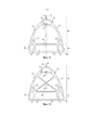
В соответствии с одним вариантом осуществления изобретение предлагает герметичную стенку резервуара, включающую в себя гофрированную герметичную мембрану, причём гофрированная герметичная мембрана включает в себя первый ряд параллельных гофров, второй ряд параллельных гофров и плоские участки, расположенные между гофрами и предназначенные для того, чтобы опираться на опорную поверхность, причём упомянутые первый и второй ряды гофров протяжены в пересекающихся направлениях и образуют множество узлов на пересечениях упомянутых гофров,In accordance with one embodiment, the invention provides a sealed tank wall including a pleated sealed membrane, wherein the pleated sealed membrane includes a first row of parallel corrugations, a second row of parallel corrugations, and flat portions located between the corrugations to rest on a supporting surface, wherein said first and second rows of corrugations are extended in intersecting directions and form a set of nodes at the intersections of said corrugations,
под гофрами первого ряда гофров расположены волнообразные усиливающие элементы,wavy reinforcing elements are located under the corrugations of the first row of corrugations,
каждый из двух последовательных волнообразных усиливающих элементов в гофре включает в себя основание, предназначенное для того, чтобы опираться на опорную поверхность, и усиливающий участок, расположенный над основанием в направлении толщины стенки резервуара, при этом два волнообразных усиливающих элемента проходят в продольном направлении в гофре по обе стороны от узла,each of two successive undulating reinforcing elements in the corrugation includes a base intended to rest on the abutment surface and a reinforcing portion located above the base in the direction of the tank wall thickness, the two undulating reinforcing elements extending longitudinally in the corrugation along both sides of the node,
упомянутые основания являются полыми, соединительный элемент расположен в гофре на уровне узла и установлен в основаниях упомянутых двух волнообразных усиливающих элементов для соединения двух волнообразных усиливающих элементов в выровненном положении.said bases are hollow, the connecting element is located in the corrugation at the level of the assembly and is installed in the bases of said two undulating reinforcing elements to connect the two undulating reinforcing elements in an aligned position.
Благодаря этим признакам, обеспечивается непрерывность между двумя последовательными волнообразными усиливающими элементами, расположенными в гофре по обе стороны узла. Благодаря этим признакам, относительное перемещение между двумя последовательными волнообразными усиливающими элементами, расположенными в гофре, ограничено, в том числе при наличии асимметричных напряжений по обе стороны узла и/или по обе стороны гофра. В частности, два последовательных волнообразных усиливающих элемента, расположенных под гофром, поддерживаются выровненными в продольном направлении гофра. Таким образом, участок гофра, расположенный с одной стороны узла, эффективно поддерживается волнообразным усиливающим элементом, расположенным под упомянутым участком гофра, причём упомянутый волнообразный усиливающий элемент удерживаться на месте за счёт взаимодействия со смежным волнообразным усиливающим элементом посредством соединительного элемента.Thanks to these features, continuity is ensured between two successive undulating reinforcing elements located in the corrugation on both sides of the assembly. Due to these features, the relative movement between two successive undulating reinforcing elements located in the corrugation is limited, including in the presence of asymmetric stresses on both sides of the assembly and / or on both sides of the corrugation. In particular, two successive undulating reinforcements located under the corrugation are kept aligned in the longitudinal direction of the corrugation. Thus, a portion of the corrugation located on one side of the assembly is effectively supported by an undulating reinforcing element located below said portion of the corrugation, wherein said undulating reinforcing element is held in place by interaction with an adjacent undulating reinforcing element by means of a connecting element.
Варианты осуществления такой стенки могут иметь один или более следующих отличительных признаков.Embodiments of such a wall may have one or more of the following features.
В одном варианте осуществления основание одного или каждого из упомянутых волнообразных усиливающих элементов имеет соответствующий выступающий участок, продольно выступающий от усиливающего участка упомянутого волнообразного усиливающего элемента в направлении другого волнообразного усиливающего элемента для взаимодействия с узлом.In one embodiment, the base of one or each of said undulating reinforcing elements has a corresponding protruding portion extending longitudinally from the reinforcing portion of said undulating reinforcing element towards the other undulating reinforcing element for interaction with the assembly.
Также волнообразные усиливающие элементы просты в изготовлении, выступающий участок основания, например, может быть изготовлен из экструдированной усиливающей части путём простого удаления усиливающего участка волнообразного усиливающего элемента на уровне упомянутого выступающего участка.Likewise, the undulating reinforcing elements are easy to manufacture, the protruding portion of the base, for example, can be made from an extruded reinforcing portion by simply removing the reinforcing portion of the undulating reinforcing element at the level of said protruding portion.
В одном варианте осуществления один конец соединительного элемента имеет сечение, размер и форма которого те же самые, что и полого сечения основания, в котором размещают упомянутый конец, для обеспечения установки без значительного зазора. Другими словами, соединительный элемент установлен и проходит в продольном направлении в основаниях с простым монтажным зазором, так что положение двух волнообразных усиливающих элементов выровнено без значительного углового зазора.In one embodiment, one end of the connecting element has a cross-section, the size and shape of which is the same as the hollow cross-section of the base, in which the said end is located, to ensure installation without significant clearance. In other words, the connecting element is installed and extends longitudinally in the bases with a simple mounting gap, so that the position of the two undulating reinforcing elements is aligned without a significant angular gap.
Волнообразный усиливающий элемент предпочтительно установлен с возможностью скольжения относительно опоры и упомянутого гофра. Таким образом, тепловое сжатие волнообразного усиливающего элемента может происходить без возникновения локальных напряжений. Кроме того, продольная установка соединительного элемента в основании волнообразного усиливающего элемента также обеспечивает тепловое сжатие волнообразного усиливающего элемента и соединительного элемента без возникновения локальных напряжений.The undulating reinforcing element is preferably slidably mounted relative to the support and said corrugation. Thus, thermal compression of the undulating reinforcing element can occur without local stresses occurring. In addition, the longitudinal positioning of the connecting element at the base of the undulating reinforcing element also allows thermal compression of the undulating reinforcing element and the connecting element without causing local stresses.
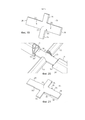
В одном варианте осуществления, по меньшей мере, один из упомянутых волнообразных усиливающих элементов соединён со связующей вставкой, взаимодействующей с упомянутым узлом, причём торцевая поверхность связующей вставки, противоположная узлу, образует упорную поверхность для торцевой поверхности волнообразного усиливающего элемента, обращённой к узлу, причём упомянутая связующая вставка включает в себя канал, продолжающий полое сечение основания волнообразного усиливающего элемента в направлении другого волнообразного усиливающего элемента, через который проходит соединительный элемент.In one embodiment, at least one of said undulating reinforcing elements is connected to a connecting insert cooperating with said assembly, wherein the end surface of the connecting insert, opposite to the assembly, forms an abutment surface for the end surface of the undulating reinforcing element facing the assembly, wherein said The connecting insert includes a channel extending the hollow section of the base of the undulating reinforcing element towards the other undulating reinforcing element through which the connecting element passes.
В одном варианте осуществления связующая вставка прикреплена к соединительному элементу.In one embodiment, the link insert is attached to the link member.
Основание волнообразного усиливающего элемента образует нижнюю часть волнообразного усиливающего элемента, а усиливающий участок образует верхнюю часть волнообразного усиливающего элемента. Основание и усиливающий участок могут быть разделены плоской или неплоской внутренней стенкой. Они также могут быть не разделены. В одном варианте осуществления основание одного из упомянутых волнообразных усиливающих элементов включает в себя нижнюю стенку, предназначенную для того, чтобы опираться на опорную поверхность. В одном варианте осуществления основание одного из упомянутых волнообразных усиливающих элементов дополнительно включает в себя верхнюю стенку, параллельную нижней стенке, предназначенной для того, чтобы опираться на опорную поверхность, причём усиливающий участок упомянутого волнообразного усиливающего элемента расположен над верхней стенкой основания.The base of the undulating reinforcing element forms the lower part of the undulating reinforcing element, and the reinforcing portion forms the upper part of the undulating reinforcing element. The base and reinforcement section can be separated by a flat or non-planar inner wall. They also may not be separated. In one embodiment, the base of one of said undulating reinforcing elements includes a bottom wall intended to be supported against the abutment surface. In one embodiment, the base of one of said undulating reinforcing elements further includes an upper wall parallel to the bottom wall intended to bear against the abutment surface, the reinforcing portion of said undulating reinforcing element being located above the upper wall of the base.
В одном варианте осуществления основание открыто на усиливающем участке. Другими словами, полое внутреннее пространство основания, в котором устанавливают конец соединительного элемента, открыто на усиливающем участке.In one embodiment, the base is exposed at the reinforcing portion. In other words, the hollow inner space of the base, in which the end of the connecting member is mounted, is open at the reinforcing portion.
В одном варианте осуществления волнообразный усиливающий элемент имеет внутреннюю поверхность, которая расположена параллельно нижней стенке основания и ограничивает полое пространство основания.In one embodiment, the undulating reinforcing element has an inner surface that is parallel to the bottom wall of the base and defines the hollow space of the base.
Внутренняя поверхность может быть получена множеством способов.The inner surface can be obtained in a variety of ways.
В одном варианте осуществления внутренняя поверхность образована поверхностью внутренней стенки, отделяющей усиливающий участок от основания.In one embodiment, the inner surface is formed by the surface of the inner wall separating the reinforcing portion from the base.
В одном варианте осуществления внутренняя поверхность образована торцевой поверхностью внутреннего ребра усиливающего участка. В одном варианте осуществления внутреннее ребро расположено в плоскости, параллельной направлению толщины стенки резервуара, от внутренней перегородки усиливающего участка, например, от зоны пересечения между двумя внутренними перегородками, размещёнными в усиливающем участке.In one embodiment, the inner surface is formed by the end surface of the inner rib of the reinforcing portion. In one embodiment, the inner rib is located in a plane parallel to the direction of the tank wall thickness from the inner baffle of the reinforcing portion, for example from the intersection between two inner baffles located in the reinforcing portion.
В одном варианте осуществления внутренняя поверхность образована одним или более боковыми участками верхней стенки основания, причём упомянутые боковые участки проходят параллельно нижней стенке от боковых стенок волнообразного усиливающего элемента.In one embodiment, the inner surface is formed by one or more side portions of the upper wall of the base, said side portions extending parallel to the lower wall from the side walls of the undulating reinforcing element.
В одном варианте осуществления один конец соединительного элемента, установленный в упомянутом основании, имеет плоское, например, прямоугольное или трапециевидное, сечение, расположенное параллельно упомянутой нижней стенке. Благодаря этим признакам, момент инерции соединительного элемента относительно оси изгиба, параллельной направлению толщины стенки резервуара, является относительно высоким.In one embodiment, one end of the connecting element mounted in said base has a planar, eg rectangular or trapezoidal, section parallel to said bottom wall. Due to these features, the moment of inertia of the connecting element about the bending axis parallel to the direction of the tank wall thickness is relatively high.
Предпочтительно в этом случае один конец соединительного элемента, установленный в основании, имеет ширину, измеренную в направлении ширины, перпендикулярном направлению толщины стенки резервуара и перпендикулярном продольному направлению гофра, превышающую толщину упомянутого конца соединительного элемента, измеренную в направлении толщины стенки резервуара.Preferably in this case, one end of the connecting element installed in the base has a width, measured in the width direction perpendicular to the tank wall thickness direction and perpendicular to the longitudinal direction of the corrugation, exceeding the thickness of said end of the connecting element measured in the tank wall thickness direction.
В одном варианте осуществления ширина конца соединительного элемента, установленного в основании, превышает половину ширины волнообразного усиливающего элемента в упомянутом направлении ширины. Такая ширина конца соединительного элемента обеспечивает высокую жёсткость в ответ на боковые напряжения, то есть в упомянутом направлении ширины.In one embodiment, the width of the end of the connecting element installed in the base is greater than half the width of the undulating reinforcing element in said width direction. This width of the end of the connecting element provides a high stiffness in response to lateral stresses, i.e. in the said width direction.
В одном варианте осуществления полый участок основания имеет плоское сечение, параллельное опорной поверхности, когда нижняя стенка упомянутого основания опирается на упомянутую опорную поверхность. Другими словами, полый участок основания имеет ширину, измеренную в направлении, перпендикулярном продольному направлению гофра и перпендикулярном направлению толщины стенки резервуара, превышающую толщину упомянутого полого участка, измеренную в направлении толщины стенки резервуара.In one embodiment, the hollow base portion has a planar cross-section parallel to the abutment surface when the bottom wall of said base rests on said abutment surface. In other words, the hollow base portion has a width, measured in a direction perpendicular to the longitudinal direction of the corrugation and perpendicular to the tank wall thickness direction, greater than the thickness of said hollow portion, measured in the tank wall thickness direction.
В одном варианте осуществления конец соединительного элемента 13 установлен в основании на расстояние от 2 до 3 см или предпочтительно на расстояние более 5 см, в частности, от 5 см до 8 см. Такое расстояние обеспечивает значительную зону взаимодействия между соединительным элементом и волнообразным усиливающим элементом, что обеспечивает стабильное поддержание выравнивания между волнообразными усиливающими элементами и надлежащее распределение боковых напряжений по значительной зоне взаимодействия.In one embodiment, the end of the connecting
В одном варианте осуществления упомянутый соединительный элемент представляет собой плоскую часть, которая имеет постоянную толщину.In one embodiment, said connecting element is a flat portion that has a constant thickness.
Соединительный элемент в виде плоской тонкой части имеет небольшой общий размер в направлении толщины стенки резервуара и, следовательно, может проходить под герметичной мембраной на уровне узла, не взаимодействуя с гофрами уплотнительной мембраны.The flat thin piece connector has a small overall dimension in the direction of the tank wall thickness and therefore can extend under the sealed membrane at the assembly level without interacting with the corrugations of the sealing membrane.
В одном варианте осуществления основания имеют две внутренние стенки, расположенные в направлении толщины, причём упомянутые внутренние стенки с нижней стенкой и, если применимо, с верхней стенкой ограничивают полый участок основания. В одном варианте осуществления полый участок основания имеет сечение прямоугольной формы.In one embodiment, the bases have two inner walls located in the thickness direction, said inner walls with a bottom wall and, if applicable, an upper wall define a hollow portion of the base. In one embodiment, the hollow base portion has a rectangular cross-section.
В одном варианте осуществления узел включает в себя вершину, причем упомянутый гофр включает в себя вогнутый участок, образующий сужение гофра, по обе стороны вершины, причём упомянутый выступающий участок и/или связующая вставка проходит в узле до сужения гофра, расположенного с соответствующей стороны вершины, или за пределы упомянутого сужения гофра.In one embodiment, the knot includes a vertex, wherein said corrugation includes a concave portion defining a tapered corrugation on both sides of the apex, wherein said protruding portion and / or link insert extends in the knot until the corrugation is tapered on the corresponding side of the apex, or beyond the said tapering of the corrugation.
Упомянутое сужение образует, например, минимальное сечение гофра в узле.Said constriction forms, for example, the minimum section of the corrugation in the knot.
В одном варианте осуществления соединительный элемент включает в себя упорную поверхность, предназначенную для ограничения вставки соединительного элемента в одно из упомянутых оснований.In one embodiment, the connector includes an abutment surface for restricting the insertion of the connector into one of said bases.
В одном варианте осуществления упорная поверхность представляет собой первую упорную поверхность, предназначенную для ограничения вставки соединительного элемента в одно из оснований, а соединительный элемент включает в себя вторую упорную поверхность, предназначенную для ограничения вставки соединительного элемента в другое основание.In one embodiment, the abutment surface is a first abutment surface for restricting insertion of the connector into one of the bases, and the joint includes a second abutment surface for restricting insertion of the joint into the other base.
Упорные поверхности могут быть получены множеством способов. В одном варианте осуществления соединительный элемент включает в себя утолщение и/или расширение, причём соединительный элемент на уровне упомянутого утолщения и/или расширения имеет сечение, размеры которого превышают размеры полого участка основания или оснований, при этом упомянутое утолщение и/или расширение имеет упорную поверхность или поверхности. В одном варианте осуществления соединительный элемент имеет центральный участок, имеющий постоянное сечение в продольном направлении гофра, причём упорная поверхность или поверхности образованы присоединяемой частью, прикреплённой к упомянутому центральному участку. Присоединяемая часть может быть получена множеством способов, например, может представлять собой винт, заклёпку, гвоздь, прикреплённый к центральному участку соединительного элемента и предпочтительно не проходящий через него. Присоединяемая часть также может представлять собой металлическую часть, прикреплённую к центральному участку соединительного элемента. Металлическая часть, которая может служить в качестве упора для первых волнообразных усиливающих элементов, например, представляет собой соединительную часть, имеющую соединительные лапки, предназначенные для взаимодействия со вторыми волнообразными усиливающими элементами, размещёнными во вторых гофрах.The abutment surfaces can be obtained in a variety of ways. In one embodiment, the connecting element includes a bulge and / or expansion, wherein the connecting element at the level of said bulge and / or expansion has a section that is larger than the hollow portion of the base or bases, wherein said bulge and / or expansion has an abutting surface or surface. In one embodiment, the connecting element has a central portion having a constant cross-section in the longitudinal direction of the corrugation, the abutment surface or surfaces being formed by an attachable portion attached to said central portion. The attachment part can be obtained in a variety of ways, for example, it can be a screw, rivet, nail, attached to the central portion of the connecting element and preferably not passing through it. The joining part can also be a metal part attached to the central portion of the connecting element. The metal part that can serve as a stop for the first undulating reinforcing elements, for example, is a connecting part having connecting tabs intended to cooperate with the second undulating reinforcing elements located in the second corrugations.
В одном варианте осуществления соединительный элемент установлен с возможностью скольжения относительно опорной поверхности, например, теплоизолирующего барьера. Другими словами, соединительный элемент не прикреплён к теплоизолирующему барьеру. Таким образом, когда ни волнообразные усиливающие элементы, ни соединительные элементы не прикреплены к опорной поверхности, волнообразные усиливающие элементы и соединительные элементы могут удерживаться между герметичной мембраной и опорной поверхностью за счёт взаимодействия между волнообразными усиливающими элементами и соединительным элементом и крепления герметичной мембраны к опорной поверхности, например, с помощью сварки.In one embodiment, the connecting element is slidably mounted relative to a support surface, such as an insulating barrier. In other words, the connecting piece is not attached to the thermal barrier. Thus, when neither undulating reinforcing elements nor connecting elements are attached to the abutment surface, the undulating reinforcing elements and connecting elements can be held between the sealed membrane and the abutment surface by interaction between the undulating reinforcing elements and the connecting element and attaching the sealed membrane to the abutment surface. for example, by welding.
В одном варианте осуществления волнообразные усиливающие элементы, расположенные под гофрами первого ряда гофров, представляют собой первые волнообразные усиливающие элементы, причём резервуар дополнительно включает в себя вторые волнообразные усиливающие элементы, расположенные под гофрами второго ряда гофров, при этом два вторых волнообразных усиливающих элемента расположены в гофре второго ряда гофров, образующем узел, по обе стороны от упомянутого узла.In one embodiment, the undulating reinforcing elements located under the corrugations of the first row of corrugations are the first undulating reinforcing elements, wherein the reservoir further includes second undulating reinforcing elements located below the corrugations of the second row of corrugations, with the two second undulating reinforcing elements located in the corrugation a second row of corrugations forming a knot on either side of said knot.
В одном варианте осуществления второй волнообразный усиливающий элемент протяжён между двумя последовательными узлами гофра.In one embodiment, the second undulating reinforcing element extends between two successive corrugation assemblies.
В одном варианте осуществления расстояние между концами основания и/или между концами связующей вставки вставок двух первых волнообразных усиливающих элементов превышает ширину вторых волнообразных усиливающих элементов, расположенных в гофре второго ряда гофров, образующем узел, причём соединительный элемент включает в себя центральный участок, расположенный между основаниями упомянутых двух первых волнообразных усиливающих элементов.In one embodiment, the distance between the ends of the base and / or between the ends of the connecting insert of the inserts of the two first undulating reinforcing elements is greater than the width of the second undulating reinforcing elements located in the corrugation of the second row of corrugations forming the assembly, where the connecting element includes a central portion located between the bases said first two undulating reinforcing elements.
В одном варианте осуществления вторые усиливающие элементы, смежные с узлом, имеют один конец, контактирующий с соединительным элементом. Благодаря этим признакам, соединительный элемент выполняет функцию упора и, следовательно, ограничивает перемещение вторых волнообразных усиливающих элементов в продольном направлении вторых гофров.In one embodiment, the second reinforcing elements adjacent to the assembly have one end in contact with the connecting element. Due to these features, the connecting element serves as a stop and therefore limits the movement of the second undulating reinforcing elements in the longitudinal direction of the second corrugations.
В одном варианте осуществления вторые волнообразные усиливающие элементы являются полыми, причём соединительный элемент включает в себя центральный участок, расположенный между основаниями первых волнообразных усиливающих элементов, при этом соединительный элемент дополнительно включает в себя две лапки и каждая из упомянутых двух лапок выступает от центрального участка соединительного элемента в продольном направлении второго ряда гофров и входит в соответствующий второй волнообразный усиливающий элемент.In one embodiment, the second undulating reinforcing elements are hollow, wherein the connecting element includes a central portion located between the bases of the first undulating reinforcing elements, the connecting element further includes two legs and each of said two legs protrudes from the central region of the connecting element in the longitudinal direction of the second row of corrugations and fits into the corresponding second corrugated reinforcing element.
В одном варианте осуществления лапки представляют собой упругие лапки, предназначенные для оказания усилия в направлении, противоположном герметичной мембране, для прижатия упомянутых вторых волнообразных усиливающих элементов к опорной поверхности.In one embodiment, the tabs are resilient tabs designed to exert force in a direction opposite to the sealed membrane to press said second undulating reinforcing elements against the abutment surface.
В одном варианте осуществления две лапки установлены во вторых волнообразных усиливающих элементах для соединения упомянутых двух вторых волнообразных усиливающих элементов с соединительным элементом. Например, в этом случае соединительный элемент имеет крестообразную форму, причём упомянутые лапки и упомянутые концы соединительного элемента образуют четыре ответвления. Крестообразный плоский соединительный элемент может быть выполнен в виде плоской части.In one embodiment, two tabs are installed in the second undulating reinforcing elements for connecting said two second undulating reinforcing elements to the connecting element. For example, in this case, the connecting element has a cruciform shape, with said legs and said ends of the connecting element forming four branches. The cruciform flat connecting element can be made in the form of a flat part.
В одном варианте осуществления соединительный элемент включает в себя крестообразную плоскую часть, причём упомянутые лапки и упомянутые концы соединительного элемента образуют четыре ответвления крестообразной части.In one embodiment, the connector includes a cruciform flat portion, said tabs and said ends of the connector defining four branches of the cruciform portion.
В одном варианте осуществления лапки и центральный участок выполнены за одно целое.In one embodiment, the tabs and the center portion are integrally formed.
В одном варианте осуществления конец одной из упомянутых лапок, удалённый от центрального участка, включает в себя удерживающий элемент, предназначенный для удержания второго волнообразного усиливающего элемента.In one embodiment, the end of one of said tabs distal from the central portion includes a holding element for holding the second undulating reinforcing element.
Удерживающий элемент может быть образован множеством способов. В одном варианте осуществления вторые волнообразные усиливающие элементы включают в себя монтажный выступ в полом участке, причём конец лапок выполнен с возможностью взаимодействия с этим выступом для удержания вторых усиливающих элементов. В одном варианте осуществления вторые волнообразные усиливающие элементы включают в себя внутренние перегородки, причём конец лапок выполнен с возможностью фиксации, например, зажима, на краевой поверхности упомянутых внутренних перегородок, обращённой к узлу.The containment member can be formed in a variety of ways. In one embodiment, the second undulating reinforcing elements include a mounting protrusion in the hollow portion, the end of the tabs being configured to engage with this protrusion to retain the second reinforcing elements. In one embodiment, the second undulating reinforcing elements include inner baffles, the end of the tabs being adapted to be fixed, for example by a clip, on an edge surface of said inner baffles facing the assembly.
В одном варианте осуществления соединительный элемент дополнительно включает в себя удерживающую пластину, прикреплённую к центральному участку соединительного элемента, причём пластина имеет лапки.In one embodiment, the connector further includes a holding plate attached to a central portion of the connector, the plate having tabs.
В одном варианте осуществления соединительный элемент включает в себя крепёжный элемент для пластины, причём упомянутый крепёжный элемент закреплён в основании на расстоянии от теплоизолирующего барьера.In one embodiment, the connecting element includes a fastening element for a plate, said fastening element being fixed in the base at a distance from the thermal barrier.
В одном варианте осуществления каждый из соответствующих вторых волнообразных усиливающих элементов включает в себя полое основание, предназначенное для того, чтобы опираться на опорную поверхность, и усиливающий участок, расположенный над основанием в направлении толщины стенки резервуара. В этом случае две лапки соединительного элемента могут быть продольно установлены в упомянутых основаниях. В результате получается монтажное устройство относительно небольшого общего размера в направлении толщины стенки.In one embodiment, each of the respective second undulating reinforcing elements includes a hollow base for abutting against the abutment surface and a reinforcing portion located above the base in the direction of the tank wall thickness. In this case, the two lugs of the connecting element can be longitudinally mounted in the said bases. The result is a mounting device of relatively small overall dimensions in the direction of wall thickness.
В одном варианте осуществления усиливающий участок волнообразного усиливающего элемента, основание которого включает в себя упомянутый выступающий участок, имеет скошенный конец в направлении узла.In one embodiment, the reinforcing portion of the undulating reinforcing element, the base of which includes said protruding portion, has a beveled end towards the assembly.
В одном варианте осуществления усиливающий участок волнообразных усиливающих элементов имеет внешнюю стенку, например, полуэллиптической выпуклой внешней формы, ограничивающую внутреннее пространство усиливающего участка, причём усиливающий участок дополнительно включает в себя внутренние усиливающие перегородки.In one embodiment, the reinforcing portion of the undulating reinforcing elements has an outer wall, such as a semi-elliptical convex outer shape, defining the interior of the reinforcing portion, wherein the reinforcing portion further includes inner reinforcing baffles.
В одном варианте осуществления внутренние перегородки располагаются между соответствующим боковым участком верхней стенки основания и внутренней поверхностью внешней стенки усиливающего участка.In one embodiment, the inner baffles are located between the corresponding side portion of the top wall of the base and the inner surface of the outer wall of the reinforcing portion.
В одном варианте осуществления усиливающий участок волнообразных усиливающих элементов имеет внешнюю стенку, причём конец упомянутой внешней стенки, обращённый к узлу, образует краевую поверхность упомянутой внешней стенки, при этом упомянутая краевая поверхность скошена таким образом, что она имеет поверхность, наклонённую относительно плоскости, перпендикулярной продольному направлению гофра, и обращённую к гофру.In one embodiment, the reinforcing portion of the undulating reinforcing elements has an outer wall, wherein the end of said outer wall facing the assembly forms an edge surface of said outer wall, wherein said edge surface is beveled such that it has a surface inclined with respect to a plane perpendicular to the longitudinal direction of the corrugation, and facing the corrugation.
В одном варианте осуществления гофрированная герметичная мембрана включает в себя гофрированную прямоугольную часть из листового металла, причём упомянутый первый ряд гофров протяжён в направлении длины части из листового металла, а упомянутый второй ряд гофров протяжён в направлении ширины части из листового металла,In one embodiment, the corrugated sealed membrane includes a corrugated rectangular sheet metal portion, wherein said first row of corrugations extends in the length direction of the sheet metal portion and said second row of corrugations extends in the width direction of the sheet metal portion,
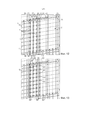
и волнообразные усиливающие элементы, расположенные под гофром первого ряда гофров, включают в себя ряд выровненных волнообразных усиливающих элементов, причём упомянутый ряд волнообразных усиливающих элементов располагается по всей длине прямоугольной части из листового металла, при этом каждый из упомянутых волнообразных усиливающих элементов включает в себя полое основание и усиливающий участок, и они попарно соединены множеством соединительных элементов, установленных в основаниях последовательных волнообразных усиливающих элементов на уровне узлов.and undulating reinforcing elements located under the corrugation of the first row of corrugations include a series of aligned undulating reinforcing elements, said row of undulating reinforcing elements being disposed along the entire length of the rectangular sheet metal portion, wherein each of said undulating reinforcing elements includes a hollow base and a reinforcing portion, and they are connected in pairs by a plurality of connecting members installed at the bases of successive undulating reinforcing members at the node level.
В одном варианте осуществления гофрированная герметичная мембрана включает в себя гофрированную прямоугольную часть из листового металла, причём упомянутый первый ряд гофров протяжён в направлении длины части из листового металла, а упомянутый второй ряд гофров протяжён в направлении ширины части из листового металла,In one embodiment, the corrugated sealed membrane includes a corrugated rectangular sheet metal portion, wherein said first row of corrugations extends in the length direction of the sheet metal portion and said second row of corrugations extends in the width direction of the sheet metal portion,
и волнообразные усиливающие элементы, расположенные под гофром первого ряда гофров, включают в себя ряд выровненных волнообразных усиливающих элементов, причём упомянутый ряд волнообразных усиливающих элементов располагается по существу по всей длине прямоугольной части из листового металла, при этом каждый из упомянутых волнообразных усиливающих элементов включает в себя полое основание, включающее в себя нижнюю стенку, предназначенную для того, чтобы опираться на опорную поверхность, и усиливающий участок, расположенный над основанием, и они попарно соединены множеством соединительных элементов, установленных в основаниях последовательных волнообразных усиливающих элементов на уровне узлов упомянутого гофра.and undulating reinforcing elements disposed below the corrugation of the first row of corrugations include a series of aligned undulating reinforcing elements, said series of undulating reinforcing elements extending substantially along the entire length of the rectangular sheet metal portion, wherein each of said undulating reinforcing elements includes a hollow base including a bottom wall intended to rest on the supporting surface and a reinforcing section located above the base, and they are connected in pairs by a plurality of connecting elements installed in the bases of successive undulating reinforcing elements at the level of the nodes of said corrugation.
В одном варианте осуществления два конца ряда волнообразных усиливающих элементов прикреплены, например, зажаты, на краях прямоугольной части из листового металла, ограничивающей гофр. Таким образом, можно работать с частью из листового металла с одним или более рядами волнообразных усиливающих элементов, предварительно прикреплённых к ней, что упрощает сборку стенки резервуара.In one embodiment, the two ends of the row of undulating reinforcements are attached, eg, clamped, at the edges of the rectangular sheet metal portion defining the corrugation. In this way, it is possible to work with a sheet metal part with one or more rows of undulating reinforcements pre-attached to it, making it easier to assemble the tank wall.
В одном варианте осуществления множество рядов волнообразных усиливающих элементов, образованных одинаковым образом, расположено в соответствующих гофрах первого ряда гофров по всей длине прямоугольной части из листового металла, например, в каждом из гофров или в только некоторых, и может быть прикреплено к прямоугольной части из листового металла одинаковым образом.In one embodiment, a plurality of rows of corrugated reinforcing elements, formed in the same way, are located in corresponding corrugations of the first row of corrugations along the entire length of the rectangular portion of sheet metal, for example, in each of the corrugations or only some of them, and may be attached to the rectangular portion of sheet metal. metal in the same way.
В одном варианте осуществления ряды волнообразных усиливающих элементов расположены в гофрах второго ряда гофров. Волнообразные усиливающие элементы могут быть прикреплены различными способами, например, за счёт взаимодействия с соединительными элементами. В одном варианте осуществления волнообразные усиливающие элементы, расположенные в гофрах второго ряда гофров, прикреплены к гофрированной части из листового металла, например, с помощью двусторонней клейкой ленты или клея.In one embodiment, the rows of undulating reinforcing elements are located in the corrugations of the second row of corrugations. Wave-like reinforcing elements can be attached in various ways, for example, by interaction with connecting elements. In one embodiment, undulating reinforcements located in the corrugations of the second row of corrugations are attached to the corrugated sheet metal portion, for example, with double-sided tape or glue.
В одном варианте осуществления множество рядов волнообразных усиливающих элементов расположено в соответствующих гофрах первого ряда гофров по существу по всей длине прямоугольной части из листового металла, а ряды вторых волнообразных усиливающих элементов расположены в гофрах второго ряда гофров, причём вторые волнообразные усиливающие элементы соединены с первыми волнообразными усиливающими элементами за счёт взаимодействия с крестообразными соединительными элементами на уровне узлов для образования каркаса гофрированной прямоугольной части из листового металла.In one embodiment, a plurality of rows of undulating reinforcing elements are located in corresponding corrugations of the first row of corrugations along substantially the entire length of the rectangular sheet metal portion, and the rows of second corrugated reinforcing elements are located in the corrugations of the second row of corrugations, with the second undulating reinforcing elements connected to the first undulating reinforcing elements. elements by interacting with cruciform connectors at the node level to form the frame of the corrugated rectangular sheet metal part.
Такой каркас может быть предварительно собран на внешней поверхности прямоугольной части из листового металла и прикреплён к последней, как описано выше. Каркас также может быть предварительно собран независимо от прямоугольной части из листового металла, предназначенной для его установки, например, с помощью монтажной рамы. Предварительная сборка каркаса облегчает сборку стенки резервуара за счёт ограничения операций.Such a framework can be pre-assembled on the outer surface of the rectangular sheet metal portion and attached to the latter as described above. The frame can also be pre-assembled independently of the rectangular sheet metal portion to be installed, for example using a mounting frame. The pre-assembly of the frame facilitates the assembly of the tank wall by limiting the operations.
В одном варианте осуществления герметичная мембрана включает в себя вторую гофрированную прямоугольную часть из листового металла, расположенную смежно с первой гофрированной прямоугольной частью из листового металла в направлении длины и приваренную к последней с обеспечением герметичности,In one embodiment, the sealed membrane includes a second corrugated rectangular sheet metal portion disposed adjacent to the first corrugated rectangular sheet metal portion in the length direction and welded to the latter in a sealable manner,
причём вторая гофрированная прямоугольная часть из листового металла снабжена вторым каркасом, образованным из первых и вторых волнообразных усиливающих элементов, расположенных в гофрах второй гофрированной прямоугольной части из листового металла и соединённых множеством соединительных элементов, установленных в упомянутых волнообразных усиливающих элементах на уровне узлов второй гофрированной прямоугольной части из листового металла.moreover, the second corrugated rectangular part of sheet metal is provided with a second frame formed from the first and second wave-like reinforcing elements located in the corrugations of the second corrugated rectangular part of sheet metal and connected by a plurality of connecting elements installed in the said wave-like reinforcing elements at the level of the nodes of the second corrugated rectangular part sheet metal.
Первый концевой усиливающий элемент, образующий конец ряда первых волнообразных усиливающих элементов первого каркаса, может быть соединён со вторым концевым усиливающим элементом, образующим конец ряда первых волнообразных усиливающих элементов второго каркаса, соединительной планкой, причём каждый из первого и второго концевых усиливающих элементов включает в себя продольное пространство, выходящее на нижней поверхности концевого усиливающего элемента, при этом соединительная планка установлена в продольном пространстве первого и второго концевых усиливающих элементов для выравнивания ряда волнообразных усиливающих элементов первого каркаса и ряда волнообразных усиливающих элементов второго каркаса.The first end reinforcing element forming the end of the row of first undulating reinforcing elements of the first frame can be connected to the second end reinforcing element forming the end of the row of the first undulating reinforcing elements of the second frame by a connecting strip, and each of the first and second end reinforcing elements includes a longitudinal a space opening out on the bottom surface of the end reinforcing member, wherein the connecting strip is positioned in the longitudinal space of the first and second end reinforcing members to align the row of undulating reinforcing members of the first frame and the row of undulating reinforcing members of the second frame.
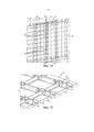
В одном варианте осуществления изобретение также обеспечивает узел, образующий предварительно собранный каркас для мембран, причём упомянутый каркас включает в себя волнообразные усиливающие элементы, предназначенные для размещения под гофрами гофрированной герметичной мембраны, включающей в себя два ряда пересекающихся гофров, один из упомянутых волнообразных гофров включает в себя плоскую нижнюю поверхность, предназначенную для того, чтобы опираться на опорную поверхность, и внутреннее пространство, смежное с нижней стенкой,In one embodiment, the invention also provides an assembly forming a pre-assembled scaffold for membranes, wherein said scaffold includes undulating reinforcing elements intended to be positioned under the corrugations of a corrugated sealed membrane including two rows of intersecting corrugations, one of said corrugated corrugations comprising itself a flat bottom surface intended to rest on a supporting surface and an interior space adjacent to the bottom wall,
упомянутый каркас включает в себя с множество рядов выровненных первых волнообразных усиливающих элементов, причём каждый ряд предназначен для размещения под гофром первого ряда гофров герметичной мембраны,said frame includes a plurality of rows of aligned first undulating reinforcing elements, each row being designed to be placed under the corrugation of the first row of corrugations of the hermetic membrane,
упомянутый каркас включает в себя множество рядов выровненных вторых волнообразных усиливающих элементов, причём каждый ряд предназначен для размещения под гофром второго ряда гофров герметичной мембраны,said frame includes a plurality of rows of aligned second undulating reinforcing elements, each row being intended to be placed under the corrugation of the second row of corrugations of the sealed membrane,
упомянутый каркас дополнительно включает в себя множество крестообразных соединительных элементов, включающих в себя лапки, размещённые в пространствах первых и вторых волнообразных усиливающих элементов на уровне пересечений рядов первых волнообразных усиливающих элементов и рядов вторых волнообразных усиливающих элементов,said frame further includes a plurality of cruciform connecting elements including tabs positioned in the spaces of the first and second undulating reinforcing elements at the intersection level of the rows of the first undulating reinforcing elements and the rows of the second undulating reinforcing elements,
упомянутый узел дополнительно включает в себя монтажную раму, расположенную вокруг концов рядов волнообразных усиливающих элементов и включающую в себя крепления, взаимодействующие с концевыми усиливающими элементами, расположенными на концах рядов первых волнообразных усиливающих элементов и рядов вторых волнообразных усиливающих элементов, для удержания узла в собранном состоянии.said assembly further includes a mounting frame disposed around the ends of the rows of undulating reinforcing elements and including fasteners interacting with end reinforcing elements located at the ends of the rows of first undulating reinforcing elements and the rows of second undulating reinforcing elements to hold the assembly in an assembled state.
В предварительно собранном каркасе волнообразные усиливающие элементы соединены крестообразными соединительными элементами и монтажной рамой в виде решётки волнообразных усиливающих элементов.In the pre-assembled frame, the undulating reinforcing elements are connected by cruciform connectors and a mounting frame in the form of an array of undulating reinforcing elements.
В одном варианте осуществления концевые первые волнообразные усиливающие элементы и концевые вторые волнообразные усиливающие элементы включают в себя открытое пространство, выходящее на нижней поверхности упомянутых концевых первых и вторых волнообразных усиливающих элементов.In one embodiment, the end first undulating reinforcing elements and the end second undulating reinforcing elements include an open space protruding at the bottom surface of said end first and second undulating reinforcing elements.
В одном варианте осуществления монтажная рама заменена гофрированной металлической пластиной, предназначенной для образования участка герметичной мембраны, и на краях металлической пластины расположены крепления.In one embodiment, the mounting frame is replaced with a corrugated metal plate to form a sealed membrane portion, and fasteners are located at the edges of the metal plate.
В одном варианте осуществления изобретение также обеспечивает способ сборки герметичной стенки резервуара для сборки стенки резервуара, включающий в себя этапы, на которых:In one embodiment, the invention also provides a method of assembling a sealed tank wall for assembling a tank wall, including the steps of:
размещают на опорной поверхности герметичного резервуара предпочтительно для каждого первого гофра гофрированной прямоугольной части из листового металла герметичной мембраны ряд первых волнообразных усиливающих элементов, причём упомянутый ряд образуют путём поочерёдной установки соединительных элементов и первых волнообразных усиливающих элементов, в частности, вышеупомянутого соединительного элемента и вышеупомянутых первых волнообразных усиливающих элементов,placed on the support surface of the sealed container, preferably for each first corrugation of the corrugated rectangular sheet metal portion of the sealed membrane, a row of first undulating reinforcing elements, said row being formed by alternately installing connecting elements and first undulating reinforcing elements, in particular the aforementioned connecting element and the aforementioned first undulating reinforcing elements,
удерживают концы упомянутого ряда первых волнообразных усиливающих элементов на опорной поверхности,hold the ends of said row of first undulating reinforcing elements on the supporting surface,
размещают на опорной поверхности предпочтительно для каждого второго гофра гофрированной прямоугольной части из листового металла вторые волнообразные усиливающие элементы,second corrugated reinforcing elements are placed on the support surface, preferably for every second corrugation of the corrugated rectangular sheet metal portion,
закрепляют на опорной поверхности гофрированную прямоугольную часть из листового металла так, чтобы ряд первых волнообразных усиливающих элементов был размещён в соответствующем первом гофре упомянутой гофрированной прямоугольной части из листового металла, а вторые волнообразные усиливающие элементы были размещены в соответствующем втором гофре гофрированной прямоугольной части из листового металла.the corrugated rectangular part of sheet metal is fixed on the support surface so that a number of first corrugated reinforcing elements are placed in the corresponding first corrugation of the said corrugated rectangular part of sheet metal, and the second corrugated reinforcing elements are placed in the corresponding second corrugation of the corrugated rectangular part of sheet metal.
В одном варианте осуществления этап удержания концов ряда первых волнообразных усиливающих элементов включает в себя этапы, на которых:In one embodiment, the step of holding the ends of the plurality of first undulating reinforcing elements includes the steps of:
размещают соединительный элемент в первом волнообразном усиливающем элементе, выступающем от гофрированной прямоугольной части из листового металла, предварительно прикреплённой к опорной поверхности,placing the connecting element in the first undulating reinforcing element protruding from the corrugated rectangular sheet metal part previously attached to the support surface,
устанавливают в упомянутом соединительном элементе концевой первый волнообразный усиливающий элемент ряда первых волнообразных усиливающих элементов.the end first undulating reinforcing element of the row of first undulating reinforcing elements is installed in said connecting element.
В одном варианте осуществления этап удержания концов ряда первых волнообразных усиливающих элементов включает в себя этап, на котором закрепляют фиксирующую поперечину на опорной поверхности, причём упомянутая фиксирующая поперечина взаимодействует с концевым первым волнообразным усиливающим элементом ряда первых волнообразных усиливающих элементов для удержания соответствующего конца ряда первых волнообразных усиливающих элементов на опорной поверхности.In one embodiment, the step of holding the ends of the row of first undulating reinforcing elements includes the step of securing the securing beam to the abutment surface, said fixing beam cooperating with the end first undulating reinforcing element of the row of first undulating reinforcing elements to hold the corresponding end of the row of first undulating reinforcing elements. elements on the support surface.
В одном варианте осуществления способ дополнительно включает в себя этап, на котором удаляют фиксирующую поперечину с опорной поверхности.In one embodiment, the method further includes removing the anchoring cross member from the abutment surface.
В одном варианте осуществления фиксирующая поперечина взаимодействует с концом множества рядов смежных первых волнообразных усиливающих элементов, расположенных на опорной поверхности, для стабилизации положения упомянутых рядов первых волнообразных усиливающих элементов.In one embodiment, the anchoring beam cooperates with the end of a plurality of rows of adjacent first undulating reinforcing elements located on the abutment surface to stabilize the position of said rows of first undulating reinforcing elements.
В одном варианте осуществления этап размещения вторых волнообразных усиливающих элементов включает в себя этап, на котором устанавливают упомянутые вторые волнообразные усиливающие элементы в смежных соединительных элементах двух рядов смежных первых волнообразных усиливающих элементов.In one embodiment, the step of positioning the second undulating reinforcing elements includes placing said second undulating reinforcing elements in adjacent connecting elements of two rows of adjacent first undulating reinforcing elements.
В одном варианте осуществления этап закрепления гофрированной прямоугольной части из листового металла на опорной поверхности включает в себя этап, на котором приваривают упомянутую гофрированную прямоугольную часть из листового металла к гофрированной прямоугольной части из листового металла, предварительно закреплённой на теплоизолирующем барьере.In one embodiment, the step of securing a corrugated rectangular sheet metal portion to a support surface includes welding said corrugated rectangular sheet metal portion to a corrugated rectangular sheet metal portion previously secured to an insulating barrier.
В одном варианте осуществления изобретение также обеспечивает волнообразный усиливающий элемент, предназначенный для размещения под гофром гофрированной герметичной мембраны, причём волнообразный усиливающий элемент включает в себя полое основание и полый усиливающий участок, расположенный над упомянутым основанием, основание включает в себя плоскую нижнюю стенку, предназначенную для того, чтобы опираться на опорную поверхность, и верхнюю стенку, отделяющую основание от усиливающего участка и параллельную упомянутой нижней поверхности, нижняя стенка и верхняя стенка соединены боковыми стенками основания, усиливающий участок включает в себя внешнюю стенку, расположенную над основанием, причём упомянутая внешняя стенка с верхней стенкой основания ограничивают внутреннее пространство усиливающего участка.In one embodiment, the invention also provides an undulating reinforcing element for placement under the corrugation of a corrugated sealed membrane, wherein the undulating reinforcing element includes a hollow base and a hollow reinforcing portion located above said base, the base includes a flat bottom wall for to rest on the supporting surface, and the upper wall separating the base from the reinforcing portion and parallel to said lower surface, the lower wall and the upper wall are connected by the side walls of the base, the reinforcing portion includes an outer wall located above the base, and the said outer wall with the upper the base wall defines the inner space of the reinforcing section.
Варианты осуществления волнообразного усиливающего элемента могут включать в себя один или более следующих признаков.Embodiments of the undulating reinforcing element may include one or more of the following features.
В одном варианте осуществления волнообразный усиливающий элемент дополнительно включает в себя внутреннюю перегородку, расположенную во внутреннем пространстве усиливающего участка. В одном варианте осуществления внутренняя перегородка имеет круглую форму, отсечённую верхней стенкой основания, причём упомянутая внутренняя перегородка проходит по касательной к внешней стенке по обе стороны от вершины упомянутой внешней стенки.In one embodiment, the undulating reinforcing element further includes an inner baffle located in the interior of the reinforcing portion. In one embodiment, the inner baffle is circular in shape, cut off by the upper wall of the base, said inner baffle extending tangentially to the outer wall on either side of the apex of said outer wall.
В одном варианте осуществления основание имеет выступающий участок, выступающий в продольном направлении относительно усиливающего участка на уровне, по меньшей мере, одного продольного конца волнообразного усиливающего элемента.In one embodiment, the base has a projecting portion longitudinally protruding with respect to the reinforcing portion at the level of at least one longitudinal end of the undulating reinforcing element.
В одном варианте осуществления изобретение также обеспечивает волнообразный усиливающий элемент, предназначенный для размещения под гофром герметичной мембраны герметичного и теплоизоляционного резервуара, причем упомянутый волнообразный усиливающий элемент включает в себя плоскую стенку, предназначенную для того, чтобы опираться на опорную поверхность, и внешнюю стенку, совместно ограничивающие внутреннее пространство упомянутого волнообразного усиливающего элемента, волнообразный усиливающий элемент дополнительно включает в себя в упомянутом внутреннем пространстве внутреннюю перегородку, имеющую круглую форму, отсечённую плоской стенкой, причём упомянутая внутренняя перегородка проходит по касательной к внешней стенке по обе стороны от вершины упомянутой внешней стенки.In one embodiment, the invention also provides an undulating reinforcing element for placement under a corrugation of a sealed membrane of a sealed and insulating reservoir, said undulating reinforcing element including a flat wall intended to rest on a support surface and an outer wall jointly defining the inner space of said undulating reinforcing element, the undulating reinforcing element further includes in said inner space an inner baffle having a circular shape cut off by a flat wall, said inner baffle extending tangentially to the outer wall on both sides of the apex of said outer wall.
В одном варианте осуществления внешняя стенка имеет полуэллиптическую выпуклую форму.In one embodiment, the outer wall has a semi-elliptical convex shape.
Стенка резервуара может образовывать часть берегового хранилища, например, для хранения СПГ, или может быть установлена на плавучей прибрежной или глубоководной конструкции, в частности, на танкере-метановозе или на любом судне, использующем горючий сжиженный газ в качестве топлива, на плавучей установке для регазификации и хранения газа (FSRU), на плавучей установке для добычи, хранения и отгрузки нефти (FPSO) и т.д.The tank wall may form part of an onshore storage facility, for example, for storing LNG, or it may be installed on a floating offshore or deep water structure, such as a methane tanker or any vessel using flammable liquefied gas as fuel, on a floating regasification unit and storage of gas (FSRU), floating installation for production, storage and offloading of oil (FPSO), etc.
В одном варианте осуществления изобретение обеспечивает судно для транспортировки холодного жидкого продукта, которое включает в себя двойной корпус и резервуар, включающий в себя вышеупомянутую герметичную стенку, расположенный в двойном корпусе.In one embodiment, the invention provides a cold liquid transport vessel that includes a double hull and a reservoir including the aforementioned sealed wall disposed in the double hull.
В одном варианте осуществления изобретение также обеспечивает способ загрузки или разгрузки такого судна, в котором холодный жидкий продукт подают по изолированным трубопроводам из плавучего или берегового хранилища в резервуар судна или из резервуара судна к плавучему или береговому хранилищу.In one embodiment, the invention also provides a method for loading or unloading such a vessel, wherein a cold liquid product is supplied through insulated pipelines from a floating or onshore storage facility to a vessel's tank or from a vessel's tank to a floating or onshore storage facility.
В одном варианте осуществления изобретение также обеспечивает систему передачи холодного жидкого продукта, причем система включает в себя вышеупомянутое судно, изолированные трубопроводы, выполненные с возможностью соединения резервуара, установленного в корпусе судна, с плавучим или береговым хранилищем, и насос для подачи потока холодного жидкого продукта по изолированным трубопроводам из плавучего или берегового хранилища в резервуар судна или из резервуара судна к плавучему или береговому хранилищу.In one embodiment, the invention also provides a cold liquid product transfer system, the system including the aforementioned vessel, insulated piping adapted to connect a vessel installed in the vessel's hull to a floating or onshore storage facility, and a pump for supplying a flow of cold liquid product through the vessel. insulated pipelines from a floating or onshore storage facility to a ship's tank or from a ship's tank to a floating or onshore storage facility.
КРАТКОЕ ОПИСАНИЕ ЧЕРТЕЖЕЙBRIEF DESCRIPTION OF DRAWINGS
Настоящее изобретение станет более понятным, и другие задачи, детали, признаки и преимущества станут более очевидными из следующего далее описания конкретных вариантов осуществления изобретения, приведенных лишь в качестве неограничивающей иллюстрации со ссылкой на приложенные чертежи.The present invention will become more clear, and other objects, details, features and advantages will become more apparent from the following description of specific embodiments of the invention, given by way of non-limiting illustration only with reference to the accompanying drawings.
Фиг. 1 представляет схематический вид в перспективе участка стенки герметичного и теплоизоляционного резервуара, на котором частично показана герметичная мембрана.FIG. 1 is a schematic perspective view of a portion of the wall of a sealed and heat-insulating vessel, in which the sealed membrane is partially shown.
Фиг. 2 представляет вид сверху теплоизолирующего барьера стенки герметичного и теплоизоляционного резервуара, показанной на фиг. 1, на котором уплотнительная мембрана не показана.FIG. 2 is a top view of the insulating barrier of the sealed and insulating tank wall shown in FIG. 1, in which the sealing membrane is not shown.
Фиг. 3 представляет вид в разрезе гофра герметичной мембраны, показанной на фиг. 1, в котором размещены волнообразные усиливающие элементы, соединённые соединительным элементом на уровне узла герметичной мембраны.FIG. 3 is a cross-sectional view of the corrugation of the sealed membrane shown in FIG. 1, which houses wave-like reinforcing elements connected by a connecting element at the level of the hermetic membrane assembly.
Фиг. 4 представляет частичный вид в перспективе волнообразного усиливающего элемента в соответствии с первым вариантом осуществления.FIG. 4 is a partial perspective view of a wave-like reinforcing element according to the first embodiment.
Фиг, 5 представляет местный вид в перспективе соединительного элемента в соответствии с первым вариантом осуществления.Fig. 5 is a fragmentary perspective view of a connecting member according to a first embodiment.
Фиг. 6 представляет вид в разрезе альтернативного варианта осуществления соединительного элемента, показанного на фиг. 5.FIG. 6 is a cross-sectional view of an alternative embodiment of the connector shown in FIG. 5.
Фиг. 7 представляет местный вид в перспективе волнообразного усиливающего элемента в соответствии со вторым вариантом осуществления.FIG. 7 is a fragmentary perspective view of a corrugated reinforcing element in accordance with a second embodiment.
Фигуры 8 и 9 представляют виды в разрезе альтернативных вариантов осуществления волнообразного усиливающего элемента, показанного на фиг. 4 или фиг. 7.Figures 8 and 9 are cross-sectional views of alternative embodiments of the undulating reinforcement shown in Figs. 4 or FIG. 7.
Фиг. 10 и 11 представляют схематические виды в перспективе волнообразных усиливающих элементов, соединённых на уровне узла соединительными элементами в соответствии с альтернативными вариантами осуществления на фиг. 5.FIG. 10 and 11 are schematic perspective views of undulating reinforcing elements connected at the assembly level by connecting elements in accordance with alternative embodiments of FIGS. 5.
Фигуры 12-14 представляют схематические виды в перспективе стенки герметичного и теплоизоляционного резервуара во время сборки, иллюстрирующие этапы установки волнообразных усиливающих элементов и герметичной мембраны на теплоизолирующем барьере.Figures 12-14 are schematic perspective views of the walls of the sealed and insulating tank during assembly, illustrating the steps of installing undulating reinforcements and the sealed membrane on the insulating barrier.
Фиг. 15 представляет схематический вид в перспективе герметичной мембраны в соответствии с альтернативным вариантом сборки герметичной мембраны на теплоизолирующем барьере.FIG. 15 is a schematic perspective view of a sealed membrane in accordance with an alternative sealed membrane assembly on an insulating barrier.
Фиг. 16 представляет схематический вид с вырезом резервуара танкера-метановоза и терминала для загрузки/разгрузки этого танкера.FIG. 16 is a schematic cutaway view of the tank of a methane tanker and the terminal for loading / unloading this tanker.
Фиг 17 представляет схематический вид в перспективе волнообразных усиливающих элементов, соединённых на уровне узла соединительным элементом в соответствии с альтернативным вариантом осуществления на фиг. 11.FIG. 17 is a schematic perspective view of undulating reinforcing elements connected at the assembly level by a connecting element in accordance with the alternative embodiment of FIG. eleven.
Фиг. 18 представляет схематический вид в перспективе связующей вставки, показанной на фиг. 17.FIG. 18 is a schematic perspective view of the bonding insert shown in FIG. 17.
Фиг. 19 представляет схематический вид в перспективе соединительного элемента, показанного на фиг. 17.FIG. 19 is a schematic perspective view of the connector shown in FIG. 17.
Фиг. 20 представляет схематический вид в перспективе волнообразных усиливающих элементов, соединённых на уровне узла соединительным элементом в соответствии с альтернативным вариантом осуществления на фиг. 17.FIG. 20 is a schematic perspective view of undulating reinforcing elements connected at the assembly level by a connecting element in accordance with the alternative embodiment of FIG. 17.
Фиг. 21 представляет схематический вид в перспективе соединительного элемента, показанного на фиг. 20.FIG. 21 is a schematic perspective view of the connector shown in FIG. twenty.
Фиг. 22 представляет вид сверху решётки из волнообразных усиливающих элементов в соответствии с альтернативным вариантом сборки волнообразных усиливающих элементов, показанным на фиг. 15.FIG. 22 is a top plan view of a wave-reinforcing array in accordance with the alternative wave-reinforcement assembly shown in FIG. 15.
Фиг. 23 представляет вид снизу усиленной герметичной мембраны, иллюстрирующий волнообразный половинчатый усиливающий элемент на уровне стыка между двумя смежными металлическими пластинами;FIG. 23 is a bottom view of a reinforced sealed membrane illustrating a wave-like half reinforcing element at a junction between two adjacent metal plates;
Фигуры 24 и 25 представляют виды в разрезе волнообразных усиливающих элементов в соответствии с альтернативными вариантами осуществления;Figures 24 and 25 are cross-sectional views of undulating reinforcing elements in accordance with alternative embodiments;
Фиг. 26 представляет схематический вид в перспективе волнообразных усиливающих элементов, показанных на фигурах 24 и 25, соединённых на уровне узла соединительным элементом;FIG. 26 is a schematic perspective view of the undulating reinforcing elements shown in Figures 24 and 25 connected at the assembly level by a connecting element;
Фигуры 27 и 28 представляют виды в разрезе волнообразных усиливающих элементов в соответствии с альтернативными вариантами осуществления.Figures 27 and 28 are cross-sectional views of undulating reinforcing elements in accordance with alternative embodiments.
Фиг. 29 представляет схематический вид в перспективе с прозрачностью узла основной герметичной мембраны, расположенного на уровне угла стенки резервуара, причём упомянутый угол образован двумя гранями упомянутой стенки резервуара, при этом в упомянутом узле размещён соединительный элемент в соответствии с одним альтернативным вариантом осуществления.FIG. 29 is a schematic perspective view with transparency of a main sealed membrane assembly positioned at the level of a corner of a tank wall, said angle being formed by two edges of said tank wall, with said assembly accommodating a connector in accordance with one alternative embodiment.
Фиг. 30 представляет схематический вид в перспективе соединительного элемента, показанного на фиг. 29.FIG. 30 is a schematic perspective view of the connector shown in FIG. 29.
ПОДРОБНОЕ ОПИСАНИЕ ВАРИАНТОВ ОСУЩЕСТВЛЕНИЯDETAILED DESCRIPTION OF IMPLEMENTATION OPTIONS
Условно выражения «внешний» и «внутренний» используются для определения положения одного элемента относительно другого со ссылкой на внутреннюю и внешнюю стороны резервуара.The terms “outer” and “inner” are used conventionally to define the position of one element relative to another with reference to the inner and outer sides of the tank.
Герметичный и теплоизоляционный резервуар для хранения и транспортировки криогенной текучей среды, например, сжиженного природного газа (СПГ), включает в себя множество стенок резервуара, каждая из которых имеет многослойную конструкцию.A sealed and insulated tank for storing and transporting a cryogenic fluid, such as liquefied natural gas (LNG), includes a plurality of tank walls, each of which has a multilayer structure.
Такая стенка резервуара включает в себя в направлении от наружной стороны к внутренней стороне резервуара теплоизолирующий барьер, закреплённый на несущей конструкции с помощью удерживающих элементов, и герметичную мембрану, поддерживаемую теплоизолирующим барьером и предназначенную для контакта с криогенной текучей средой, содержащейся в резервуаре.Such a tank wall includes, in the direction from the outside to the inside of the tank, a heat-insulating barrier secured to the supporting structure by means of retaining elements, and a sealed membrane supported by a heat-insulating barrier and intended for contact with a cryogenic fluid contained in the reservoir.
Несущая конструкция, в частности, может представлять собой самонесущую металлическую пластину или, в более общем смысле, может представлять собой жёсткую перегородку любого типа, имеющую подходящие механические свойства. Несущая конструкция, в частности, может быть образована корпусом или двойным корпусом судна. Несущая конструкция включает в себя множество стенок, определяющих общую форму резервуара, обычно многогранную форму.The supporting structure can in particular be a self-supporting metal plate or, more generally, can be any type of rigid partition having suitable mechanical properties. The supporting structure, in particular, can be formed by the hull or the double hull of the ship. The supporting structure includes a plurality of walls defining the overall shape of the tank, usually a multi-faceted shape.
Резервуар также может включать в себя множество теплоизолирующих барьеров и герметичных мембран. Например, в направлении от наружной стороны к внутренней стороне резервуара, резервуар может включать в себя вспомогательный теплоизолирующий барьер, закреплённый на несущей конструкции, вспомогательную герметичную мембрану, поддерживаемую вспомогательным теплоизолирующим барьером, основной теплоизолирующий барьер, опирающийся на вспомогательную герметичную мембрану, и основную герметичную мембрану, опирающуюся на основной теплоизолирующий барьер. Теплоизолирующий барьер может быть изготовлен множеством способов, из множества материалов и в соответствии с известными технологиями, например, как описано в документе WO2017017337 или WO2017006044. Герметичные мембраны могут состоять из гофрированных прямоугольных металлических частей, включающих в себя ряд гофров разных или одинаковых размеров.The reservoir can also include a variety of thermal barriers and sealed membranes. For example, in the direction from the outside to the inside of the tank, the tank may include an auxiliary insulating barrier secured to a supporting structure, an auxiliary sealed membrane supported by an auxiliary insulating barrier, a main insulating barrier supported by an auxiliary sealed membrane, and a main sealed membrane. resting on the main thermal insulation barrier. The thermal barrier can be made in a variety of ways, from a variety of materials and in accordance with known techniques, for example, as described in document WO2017017337 or WO2017006044. Sealed membranes can be composed of corrugated rectangular metal parts that include a number of corrugations of different or equal sizes.
Фиг. 1 показывает часть герметичной мембраны 1, предназначенной для контакта с текучей средой, содержащейся в резервуаре, и закреплённой на теплоизолирующем барьере 2. Герметичная мембрана 1 включает в себя множество гофрированных металлических пластин прямоугольной формы, закреплённых на теплоизолирующем барьере 2. Герметичная мембрана 1 включает в себя первый ряд параллельных гофров, называемых высокими гофрами 3, протяжённых в первом направлении, и второй ряд параллельных гофров, называемых низкими гофрами 4, протяжённых во втором направлении. В данном случае выражения «высокие» и «низкие» имеют относительное значение и означают, что первый ряд гофров 3 имеет большую высоту, чем второй ряд гофров 4. Первое и второе направления перпендикулярны. Следовательно, высокие гофры 3 образуют с низкими гофрами 4 узлы 5 на уровне каждого пересечения между ними. Другими словами, каждый гофр 3, 4 включает в себя последовательность продольных участков 6 и узлов 5, причём упомянутые узлы образованы пересечением упомянутых гофров 3, 4 с перпендикулярным гофром 4, 3. Продольные участки 6 имеют по существу постоянное сечение, при этом изменение сечения гофра 3, 4 на уровне пересечения между двумя гофрами 3, 4 означает начало узла 5. Однако продольный участок 6 может включать в себя локальные изменения формы, деформации (не показаны), например, как описано в документе FR2861060.FIG. 1 shows a portion of a sealed membrane 1 intended for contact with a fluid contained in a reservoir and secured to a thermal insulating
Узел 5 включает в себя складку 7, которая продолжает верхнюю краевую поверхность 8 (смотри фиг. 3) высокого гофра 3, образующего упомянутый узел. Верхняя краевая поверхность 8 высокого гофра 3 включает в себя пару вогнутых гофров 9 (более подробно показаны на фиг. 3), вогнутая сторона которых обращена внутрь резервуара, и которые расположены по обе стороны от сгиба 7.The
Другие возможные признаки и детали герметичной мембраны 1, гофрированных металлических пластин, образующих упомянутую герметичную мембрану 1, и конструкции узлов 5 описаны в документе WO2017017337 или WO2017006044. Например, герметичная мембрана 1 может быть выполнена из листа нержавеющей стали или алюминия, может иметь толщину приблизительно 1,2 мм и может быть получена путём вытяжки или гибки. Также возможны другие металлы или сплавы и другая толщина.Other possible features and details of the sealed membrane 1, the corrugated metal plates forming said sealed membrane 1, and the structures of the
Как показано на фигурах 1 и 2, ряды первых волнообразных усиливающих элементов 11 расположены под высокими гофрами 3. Подобным образом ряды вторых волнообразных усиливающих элементов 12 расположены под низкими гофрами 4. Волнообразные усиливающие элементы 11, 12 позволяют поддерживать и усиливать гофры 3, 4 герметичной мембраны при наличии напряжений, связанных, например, с движением текучей среды в резервуаре. Волнообразные усиливающие элементы 11, 12 могут быть выполнены из множества материалов, например, из металлов, в частности, алюминия, металлических сплавов, пластиков, в частности, полиэтилена, поликарбоната, полиэфиримида, или композитных материалов, содержащих волокна, в частности, стеклянные волокна, связанные пластичной смолой.As shown in Figures 1 and 2, the rows of first
Первые волнообразные усиливающие элементы 11 расположены под каждым продольным участком 6 высоких гофров 3. Подобным образом вторые волнообразные усиливающие элементы 12 расположены под каждым продольным участком 6 низких гофров 4.The first
Однако напряжения в резервуаре не всегда одинаковы. Таким образом, высокий гофр 3 может подвергаться асимметричным напряжениям по длине. Асимметричные напряжения приводят к воздействию бокового напряжения на продольный участок 6 высокого гофра 3, при этом смежный продольный участок 6 упомянутого высокого гофра 3 не подвергается аналогичному напряжению. При наличии таких асимметричных напряжений высокий гофр 3 может подвергаться значительному скручиванию на уровне узла 5, разделяющего два последовательных продольных участка 6, подверженных упомянутому асимметричному напряжению.However, the stresses in the reservoir are not always the same. Thus, the high corrugation 3 can be subjected to asymmetric stresses along the length. Asymmetric stresses lead to lateral stress on the
Для предотвращения этого, как более подробно объяснено ниже со ссылкой на фигуры 3-5, первые волнообразные усиливающие элементы 11, расположенные под одним высоким гофром 3, соединены соединительным элементом 13. Соединительные элементы 13 расположены под высоким гофром 3 на уровне каждого узла 5 для соединения двух последовательных первых волнообразных усиливающих элементов 11 в упомянутом высоком гофре 3.To prevent this, as explained in more detail below with reference to Figures 3-5, the first
Соединительные элементы 13 обеспечивают стабильное выравнивание двух последовательных первых волнообразных усиливающих элементов 11. Таким образом, каждый высокий гофр 3 поддерживается рядом первых волнообразных усиливающих элементов 11, попарно соединённых вдоль упомянутого высокого гофра 3 в выравнивании, соответствующем продольному направлению упомянутого высокого гофра 3. Таким образом, если высокий гофр 3 подвергается асимметричному напряжению, соединительный элемент 13 обеспечивает сохранение выравнивания последовательных первых волнообразных усиливающих элементов 11 и, следовательно, позволяет предотвратить скручивание герметичной мембраны 1 на уровне узла 5. В частности, первый волнообразный усиливающий элемент 11, расположенный под продольным участком 6, подверженным напряжению, передаёт часть усилия на первые волнообразные усиливающие элементы 11, с которыми он соединён с помощью соединительных элементов 13, что обеспечивает распределение упомянутого усилия на смежные первые волнообразные усиливающие элементы 11. Другими словами, соединительные элементы 13 обеспечивают по существу аналогичное поведение ряда первых волнообразных усиливающих элементов 11 при наличии асимметричных напряжений и симметричных напряжений вдоль высокого гофра 3, под которым расположен упомянутый ряд первых волнообразных усиливающих элементов 11. Таким образом, высокие гофры 3 равномерно усилены по всей длине, и вероятность значительного скручивания в случае асимметричных напряжений уменьшается или исключается.The connecting
Как показано на фиг. 2, расстояние, разделяющее два последовательных первых волнообразных усиливающих элемента 11, больше, чем ширина вторых волнообразных усиливающих элементов 12. Кроме того, вторые волнообразные усиливающие элементы 12 проходят в продольных участках 6 низких гофров 4 до тех пор, пока они войдут в контакт с соединительными элементами 13, размещёнными в узлах 5, образованных на концах упомянутых продольных участков 6. Таким образом, концы 14 каждого второго волнообразного усиливающего элемента 12 расположены между двумя смежными первыми волнообразными усиливающими элементами 11. Таким образом, вторые волнообразные усиливающие элементы 12 зафиксированы на уровне узлов, с одной стороны, в поперечном направлении за счёт первых волнообразных усиливающих элементов 11, а, с другой стороны, в продольном направлении за счёт соединительных элементов 13, размещённых в упомянутых узлах.As shown in FIG. 2, the distance separating two successive first
Первые волнообразные усиливающие элементы 11 описаны ниже со ссылкой на фигуры 3 и 4. Первый волнообразный усиливающий элемент 11 включает в себя основание 15 и усиливающий участок 16.The first
Основание 15 имеет нижнюю стенку 17, две боковые стенки 18 и верхнюю стенку 19. Нижняя стенка 17 является плоской и опирается на теплоизолирующий барьер 2. Верхняя стенка 19 является плоской и параллельна нижней стенке 17. Боковые стенки соединяют нижнюю стенку 17 и верхнюю стенку 19 по всей длине первого волнообразного усиливающего элемента 11. Нижняя стенка 17, боковые стенки 18 и верхняя стенка 19 совместно ограничивают полое внутреннее пространство основания 15.The
Как показано на фиг. 4, основание 15 предпочтительно включает в себя усиливающие стенки 21 в полом пространстве, соединяющие нижнюю стенку 17 и верхнюю стенку 19. Усиливающие стенки 21 усиливают основание 15 и, в частности, позволяют основанию 15 сохранять свою форму даже при воздействии сильных напряжений.As shown in FIG. 4, the base 15 preferably includes reinforcing
Усиливающий участок 16 первого волнообразного усиливающего элемента 11 включает в себя внешнюю стенку 22. Внешняя стенка 22 предпочтительно имеет форму, комплементарную форме высокого гофра 3. Таким образом, как показано на фиг. 4, внешняя стенка 22 имеет куполообразную форму.The reinforcing
Усиливающий участок 16 предпочтительно является полым для обеспечения циркуляции инертирующего газа или газа для обнаружения утечек в теплоизолирующем барьере 2. Таким образом, верхняя стенка 19 основания 15 и внешняя стенка 22 вместе ограничивают полое внутреннее пространство усиливающего участка 16.The
Усиливающий участок 16 предпочтительно включает в себя внутренние перегородки 23 для усиления упомянутого усиливающего участка 16. На фиг. 4 внутренние перегородки 23 пересекаются по существу по центру усиливающего участка 16.The reinforcing
Основание 15 имеет длину, превышающую длину усиливающего участка 16. Таким образом, как показано на фиг. 4, основание 15 имеет выступающий участок 24, который выступает в продольном направлении за пределы усиливающего участка 16.The
Первый волнообразный усиливающий элемент 11 может быть изготовлен множеством способов. Первый волнообразный усиливающий элемент 11 предпочтительно сначала изготавливают с постоянным сечением по всей длине упомянутого первого волнообразного усиливающего элемента 11 путём экструзии. После этого обрабатывают усиливающий участок 16 для получения выступающего участка 24 основания 15. Усиливающий участок 16 предпочтительно обрабатывают для получения скоса на уровне стыка с выступающим участком 24, поэтому усиливающий участок имеет максимальную длину на уровне стыка с основанием 15.The first
Фиг. 3 показывает два первых волнообразных усиливающих элемента 11 на уровне узла 5, соединённых соединительным элементом 13. Как объяснено выше, высокий гофр 3 имеет на уровне узла 5 два вогнутых участка 9, разделённых сгибом 7. Вогнутые гофры 9 образуют уменьшение высоты высокого гофра 3 на уровне узла 5. Следовательно, верхняя краевая поверхность 8 высокого гофра 3 имеет постоянное сечение до уменьшения размера, образованного вогнутыми гофрами 9 на уровне узла 5.FIG. 3 shows two first
Длина усиливающего участка 16 по вершине внешней стенки 22, например, равна длине продольного участка 6 высокого гофра 3, который имеет постоянное сечение между двумя узлами 5. Участок постоянного сечения заканчивается в месте, где высокий гофр 3 имеет небольшое боковое сужение, обозначающее начало узла 5, геометрия которого является сложной, как объяснено выше. Кроме того, скошенная форма усиливающих участков 16 по существу соответствует наклону бокового сужения, таким образом, усиливающий участок 16 максимально приближается к узлу 5 для оптимальной поддержки гофра.The length of the reinforcing
Кроме того, краевая поверхность внешней стенки 22 также скошена (не показано). Таким образом, краевая поверхность внешней стенки имеет поверхность, наклонённую относительно продольной оси усиливающего участка 16. Скошенная краевая поверхность имеет скошенную поверхность, обращённую к высокому гофру 3. Таким образом, если первый волнообразный усиливающий элемент 11 перемещается в продольном направлении в высоком гофре, в котором он размещён, контакт между усиливающим участком 16 и высоким гофром 3 происходит на уровне скошенной краевой поверхности, поверхность которой повторяет форму высокого гофра. Следовательно, этот контакт происходит без риска повреждения высокого гофра из-за взаимодействия между скошенной краевой поверхностью и высоким гофром 3, при этом отсутствует вероятность того, что краевая поверхность внешней стенки 22 повредит высокий гофр 3.In addition, the edge surface of the
Основание 15 имеет ширину меньше, чем ширина бокового сужения, обозначающего начало узла 5. Другими словами, расстояние, разделяющее боковые стенки 18 основания 15 меньше, чем ширина высокого гофра 3 на уровне бокового сужения, обозначающего начало узла 5. Таким образом, выступающий участок 24 основания 15 может быть вставлен в узел 5, как показано на фиг. 3.The
Выступающий участок 24 первого волнообразного усиливающего элемента 11 предпочтительно продольно выступает в узел 5 в направлении сгиба 7 за пределы минимального уменьшения высоты высокого гофра 3, образованного вогнутым участком 9. Однако расстояние, разделяющее выступающие участки 24 двух последовательных первых волнообразных усиливающих элементов 11, превышает ширину смежного второго волнообразного усиливающего элемента 12, размещённого в низком гофре 4, образующем узел 5. Другими словами, выступающие участки 24 первых волнообразных усиливающих элементов 11, заканчиваются перед низким гофром 4, так что они не попадают на линию прохождения упомянутого низкого гофра 4. Таким образом, как показано на фиг. 2, вторые волнообразные усиливающие элементы 12 могут быть протяжены так, что они могут быть вставлены в узел 5, расположенный между основаниями 15 двух первых волнообразных усиливающих элементов 11. Таким образом, упомянутые вторые волнообразные усиливающие элементы 12 могут удерживаться на месте за счёт взаимодействия с основаниями 15 упомянутых первых волнообразных усиливающих элементов 11.The protruding
Соединительный элемент 13 размещён в основаниях 15 двух последовательных первых волнообразных усиливающих элементов 11 для соединения упомянутых последовательных первых волнообразных усиливающих элементов 11.A connecting
Фиг. 5 иллюстрирует пример соединительного элемента, вставленного в основания 15 двух последовательных первых волнообразных усиливающих элементов 11, как показано на фиг. 3. Такой соединительный элемент имеет форму параллелепипедной планки 25, ширина которой меньше чем расстояние, разделяющее усиливающие стенки 21 оснований 15. В частности, планка 25 имеет сечение, размеры которого немного меньше, чем размеры пространства 20 (смотри фиг. 4), ограниченного нижней стенкой 17, верхней стенкой 19 и усиливающими стенками 21 оснований 15.FIG. 5 illustrates an example of a connecting element inserted into the
Взаимосоответствующие формы соединительного элемента 13 и пространства 20 двух последовательных первых волнообразных усиливающих элементов 11 позволяют вставлять соединительный элемент 13 в пространства 20 с надлежащим взаимодействием между соединительным элементом 13 и основаниями упомянутых первых волнообразных усиливающих элементов 11, что обеспечивает поддержание выравнивания упомянутых первых волнообразных усиливающих элементов 11.Corresponding shapes of the connecting
Например, соединительный элемент 13 может быть вставлен в каждое пространство 20 на расстояние от 2 см до 3 см или предпочтительно на расстояние более 5 см, в частности, от 5 см до 8 см, для взаимодействия с первыми волнообразными усиливающими элементами 11 на длине, достаточной для стабильного поддержания выравнивания упомянутых первых волнообразных усиливающих элементов 11.For example, the connecting
Как показано на фиг. 2, вторые волнообразные усиливающие элементы 12 вставлены в узлы 5 с минимальным зазором или даже контактируют с соединительными элементами 13. Таким образом, вторые волнообразные усиливающие элементы 12 могут фиксировать соединительный элемент 13, с которым они взаимодействуют, при перемещении.As shown in FIG. 2, the second
Соединительный элемент 13 в виде планки 25 предпочтительно может быть вставлен в основание 15 скользящим образом, что позволяет игнорировать производственные допуски и обеспечивает более или менее глубокую вставку планки 25 в основания 15 для устранения каких-либо производственных зазоров. Таким образом, планка 25 имеет центральный участок 27 и два конца 28, разделённых упомянутым центральным участком 27. Центральный участок 27 соответствует расстоянию, разделяющему два основания 15, а концы 28 представляют собой участки упомянутой планки 25, вставляемые в основания 15. Относительное скольжение между соединительным элементом 13 и первыми волнообразными усиливающими элементами 11 также позволяет компенсировать тепловое сжатие волнообразных усиливающих элементов без возникновения напряжений.The connecting
Планка 25 может быть изготовлена множеством способов и может быть сплошной или полой.The
Фиг. 6 иллюстрирует альтернативный вариант осуществления планки 25, показанной на фиг. 5. В альтернативном варианте осуществления соединительный элемент 13 имеет центральный участок 27, разделяющий два продольных конца 28. Центральный участок 27 имеет большую толщину по сравнению с концами 28. Аналогично планке 25, концы 28 имеют сечение, форма которого взаимосоответствует форме пространств 20 первых волнообразных усиливающих элементов 11. Таким образом, каждый конец 28 соединительного элемента 13 вставляется в соответствующее пространство 20 до тех пор, пока основание 15, включающее в себя упомянутое пространство 20, не упрётся в центральный участок 27. Другими словами, центральный участок 27 образует две упорные поверхности, ограничивающие вставку соединительного элемента 13 в пространства 20 оснований 15, в которые вставлены концы 28 упомянутого соединительного элемента 13.FIG. 6 illustrates an alternative embodiment of the
Упорные поверхности, позволяющие ограничить вставку соединительного элемента 13 в основания 15, могут быть получены множеством способов. В варианте осуществления, который не показан, для образования упомянутых упорных поверхностей к верхней поверхности планки 25 прикреплены присоединяемые части. Таким образом, например, на планке 25 могут быть закреплены винты, но они не проходят сквозь неё, в результате чего упомянутая планка 25 имеет выступы, при этом вставка планки 25 в пространства 20 ограничивается упором верхней стенки 19 основания в эти винты. В другом варианте осуществления, который не показан, такую же функцию могут выполнять заклёпки, причём заклёпки предпочтительно выступают только из верхней поверхности планки 25. В другом варианте осуществления, который не показан, но получен на основе фиг. 10, часть 33 может быть расширена так, что её края, обращённые к первым волнообразным усиливающим элементам 11, служат в качестве упоров для упомянутых первых волнообразных усиливающих элементов 11 в дополнение к обеспечению соединения с лапками 34.The abutment surfaces allowing to restrict the insertion of the connecting
Фигуры 7-9 иллюстрируют альтернативные варианты осуществления первого волнообразного усиливающего элемента 11. Элементы, идентичные или выполняющие ту же функцию, что и элементы, описанные выше со ссылкой на фигуры 1-6, обозначены теми же ссылочными позициями. Альтернативные варианты первых волнообразных усиливающих элементов 11 также применимы в отношении вторых волнообразных усиливающих элементов 12.Figures 7-9 illustrate alternative embodiments of the first
Фиг. 7 иллюстрирует первый альтернативный вариант первого волнообразного усиливающего элемента 11, показанного на фиг. 4. Альтернативный вариант отличается от варианта, показанного на фиг. 4, тем, что конец усиливающего участка 16, от которого выступает выступающий участок 24, является прямым, то есть не скошен, таким образом, усиливающий участок имеет постоянную длину.FIG. 7 illustrates a first alternative embodiment of the first
Фиг. 8 иллюстрирует второй альтернативный вариант первого волнообразного усиливающего элемента 11. На фиг. 8 первый волнообразный усиливающий элемент 11 включает в себя основание 15 и усиливающий участок 16.FIG. 8 illustrates a second alternative embodiment of the first
Основание 15 включает в себя нижнюю стенку 17, две боковые стенки 18 и верхнюю стенку 19. Нижняя стенка 17, боковые стенки 18 и верхняя стенка 19 совместно образуют полый канал в основании 15. Основание 15 дополнительно включает в себя в упомянутом полом канале усиливающие стенки 21, соединяющие нижнюю стенку 17 и верхнюю стенку 19.The
Усиливающий участок включает в себя внешнюю стенку 22. Внешняя стенка имеет форму, взаимосоответствующую форме высокого гофра 3, под которым должен быть размещён первый волнообразный усиливающий элемент. Внешняя стенка 22 обычно имеет две боковые стенки 29, каждая из которых образует боковую поверхность усиливающего участка 16. Каждая боковая стенка 29 протяжена от основания 15, в частности, от верхнего конца соответствующей боковой стенки 18 основания 15, до вершины усиливающего участка 16. Внешняя стенка с верхней стенкой 19 основания 15 ограничивают полый канал в усиливающем участке 16.The reinforcing section includes an
Усиливающий участок дополнительно включает в себя внутреннюю перегородку 23. Внутренняя перегородка в альтернативном варианте, показанном на фиг. 8, имеет кольцевую форму, отсечённую верхней стенкой 19 основания 15. Внутренняя перегородка 23 отсечённой кольцевой формы проходит по касательной к боковым стенкам 29 внешней стенки 22. В частности, каждый из двух первых криволинейных участков 30 внутренней перегородки 23 соединяет верхнюю стенку 19 основания 15 с внутренней поверхностью соответствующей боковой стенки 29. Второй криволинейный участок 31 соединяет две боковые стенки 29 внешней стенки 22.The reinforcing portion further includes an
Стык между каждым первым криволинейным участком 30 и верхней стенкой 19 основания 15 предпочтительно выполнен на верхней поверхности упомянутой верхней стенки 19 на уровне стыка между нижней поверхностью упомянутой верхней стенки 19 и соответствующей усиливающей перегородкой 21 основания 15.The joint between each first
В альтернативном варианте, показанном на фиг. 9, усиливающий участок 16 дополнительно включает в себя пересекающиеся усиливающие перегородки 32. Пересекающиеся усиливающие перегородки 32 соединяют боковую стенку 29 соответствующей внешней стенки 22 и верхнюю стенку 19 основания. Пересекающиеся усиливающие перегородки 32 пересекаются на уровне плоскости X симметрии первого волнообразного усиливающего элемента, продолжающейся в продольном направлении первого волнообразного усиливающего элемента 11 перпендикулярно верхней стенке 19 основания 15 и проходящей через вершину 10 усиливающего участка 16. Усиливающая перегородка 32, протяжённая от одной из боковых стенок 29, предпочтительно соединяется с верхней стенкой 19 основания 15 на уровне стыка между первым криволинейным участком 30, соединяющим другую боковую стенку 29 и верхнюю стенку 19 основания 15.In an alternative embodiment shown in FIG. 9, the reinforcing
В альтернативном варианте, который не показан, усиливающие перегородки 32 первого волнообразного усиливающего элемента 11, который показан на фиг. 9, заменены усиливающей перегородкой, параллельной верхней стенке 19. Такая усиливающая перегородка, например, соединяется с внутренней поверхностью боковой стенки 29, образованной внешней стенкой 22, на уровне стыка по касательной между внутренней перегородкой 23 отсечённой кольцевой формы и упомянутой внутренней поверхностью боковой стенки 29.Alternatively, not shown, the reinforcing
Фигуры 10 и 11 представляют схематические виды в перспективе волнообразных усиливающих элементов, соединённых на уровне узла соединительными элементами в соответствии с альтернативными вариантами осуществления на фиг. 5. Элементы, идентичные или выполняющие ту же функцию, что и элементы, описанные выше, обозначены теми же ссылочными позициями.Figures 10 and 11 are schematic perspective views of undulating reinforcing elements connected at the assembly level by connecting elements in accordance with alternative embodiments of Figs. 5. Elements that are the same or have the same function as those described above are denoted by the same reference numbers.
Соединительный элемент 13, показанный на фиг. 10, включает в себя планку 25, как описано со ссылкой на фиг. 5. Таким образом, планка 25 включает в себя центральный участок 27, разделяющий два конца 28 упомянутой планки 25, размещённые в основаниях 15 двух последовательных первых волнообразных усиливающих элементов 11.The connecting
В этом варианте на центральном участке 27 планки 25 закреплена пластина 33. Пластина 33 закреплена таким образом, что она не проходит через планку 25, так что планка 25 не выступает в направлении теплоизолирующего барьера 2.In this embodiment, a
Пластина 33 имеет две лапки 34, каждая из которых выступает вбок от планки 25. Каждая из лапок 34 размещена в полом участке второго волнообразного усиливающего элемента 12.The
Каждая лапка 34 предпочтительно является упругой. В варианте осуществления, показанном на фиг. 10, упругие лапки 34 образованы загнутым концом пластины 33. Упругие лапки 34 выполнены так, чтобы оказывать на вторые волнообразные усиливающие элементы 12, в которые они вставлены, удерживающее усилие в направлении теплоизолирующего барьера 2. Таким образом, упругие лапки 34 предпочтительно позволяют удерживать в заданном положении вторые волнообразные усиливающие элементы 12, на теплоизолирующем барьере 2, в которые они вставлены.Each
В варианте осуществления, показанном на фиг. 10, каждый из первых волнообразных усиливающих элементов 11 и вторых волнообразных усиливающих элементов имеет основание 15 и усиливающий участок 16. Однако основания 15 вторых волнообразных усиливающих элементов 12 не включают в себя выступающий участок 24 в отличие от первых волнообразных усиливающих элементов 11.In the embodiment shown in FIG. 10, each of the first
Для упрощения фигур 10 и 11 усиливающие стенки 21 и внутренние перегородки 23 волнообразных усиливающих элементов 11, 12 не показаны, при этом волнообразные усиливающие элементы 11, 12, показанные на фигурах 10 и 11, включают или не включают в себя усиливающие стенки 21 и/или внутренние перегородки 23, как описано выше.To simplify Figures 10 and 11, the reinforcing
Вторые волнообразные усиливающие элементы, прикреплённые к соединительному элементу, могут удерживаться множеством других способов. В варианте осуществления, который не показан, вторые волнообразные усиливающие элементы 12 включают в себя внутренние усиливающие перегородки, как на фиг. 3, и лапки 34 имеют концы, которые зажимаются на упомянутых внутренних перегородках вторых волнообразных усиливающих элементов 12. В другом варианте осуществления, который не показан, полый участок вторых волнообразных усиливающих элементов имеет выступ, на котором зажимается конец лапки 34.The second undulating reinforcing elements attached to the connecting element can be held in a variety of other ways. In an embodiment not shown, the second
Вариант осуществления, показанный на фиг. 11, отличается от варианта осуществления, показанного на фиг. 10, тем, что лапки 34 выполнены за одно целое с планкой 25. Соединительный элемент 13 обычно имеет крестообразную форму, включающую в себя четыре лапки, причём две противоположные лапки 28 размещены в основаниях 15 первых волнообразных усиливающих элементов 11, и две противоположные лапки 34 размещены в основаниях 15 вторых волнообразных усиливающих элементов 12. Другими словами, соединительный элемент 13, показанный на фиг. 11, подобен сплошной или полой планке 25, центральный участок 27 которой выступает вбок, образуя лапки 34, размещённые в основаниях 15 вторых волнообразных усиливающих элементов 12. Например, лапки 34 соединительного элемента 13 могут быть вставлены в основания 15 вторых волнообразных усиливающих элементов 12 на расстояние от 2 м до 3 см или предпочтительно на расстояние более 4 см, в частности, от 4 см до 6 см, для взаимодействия со вторыми волнообразными усиливающими элементами 12 на длине, достаточной для стабильного поддержания выравнивания упомянутых вторых волнообразных усиливающих элементов 12.The embodiment shown in FIG. 11 differs from the embodiment shown in FIG. 10, in that the
Фигуры 12-14 представляют схематические виды в перспективе герметичного и теплоизоляционного резервуара во время сборки, иллюстрирующие этапы крепления волнообразных усиливающих элементов и герметичной мембраны к теплоизолирующему барьеру.Figures 12-14 are schematic perspective views of the sealed and insulating container during assembly, illustrating the steps of attaching undulating reinforcements and the sealed membrane to the insulating barrier.
Во время сборки резервуара ряды волнообразных усиливающих элементов 11, 12 устанавливают и удерживают на теплоизолирующем барьере 2 перед покрытием их гофрированными металлическими пластинами. Гофрированные металлические пластины имеют прямоугольную форму и имеют высокие гофры 3 и низкие гофры 4. Края упомянутых гофрированных металлических пластин пересекают высокие гофры 3 и низкие гофры 4 между двумя последовательными узлами упомянутых гофров 3, 4. Таким образом, волнообразные усиливающие элементы 11, 12, расположенные под гофрами 3, 4 на уровне краёв гофрированных металлических пластин, совместно покрыты двумя последовательными гофрированными металлическими пластинами.During assembly of the reservoir, rows of undulating reinforcing
На фиг. 12 частично показана герметичная мембрана 1 во время сборки. На фиг. 12 некоторые металлические пластины герметичной мембраны 1 уже закреплены на металлических вставках 35 теплоизолирующего барьера 2. Таким образом, участки 36 волнообразных усиливающих элементов 11, 12, размещённые под гофрами 3, 4 уже установленных металлических пластин, частично не покрыты упомянутыми и уже установленными металлическими пластинами.FIG. 12 partially shows the sealed diaphragm 1 during assembly. FIG. 12, some metal plates of the sealed membrane 1 are already fixed on the metal inserts 35 of the heat-insulating
Во-первых, как показано на фиг. 12, ряды 37 первых волнообразных усиливающих элементов 11 размещают на теплоизолирующем барьере 2. Ряды 37 включают в себя множество первых волнообразных усиливающих элементов 11, соединённых соединительными элементами для образования последовательности первых волнообразных усиливающих элементов 11.First, as shown in FIG. 12,
Кроме того, первый конец 38 рядов 37 первых волнообразных усиливающих элементов соединяют с помощью соединительного элемента 13 с первыми волнообразными усиливающими элементами 11, частично покрытыми металлической пластиной, уже закреплённой на изолирующем барьере. Таким образом, первый конец 38 рядов 37 удерживается на теплоизолирующем барьере 2 за счёт упомянутой металлической пластины, уже закреплённой на теплоизолирующем барьере 2.In addition, the first end 38 of the
Второй конец 39 рядов 37 первых волнообразных усиливающих элементов 11, противоположный первому концу 38, удерживается на теплоизолирующем барьере 2 с помощью фиксирующей поперечины 40. Фиксирующую поперечину 40 временно закрепляют на теплоизолирующем барьере 2 с помощью любого подходящего средства, например, с помощью винтов, гвоздей и т.д. Фиксирующую поперечину 40, например, временно крепят к металлическим вставкам 35, причём упомянутые металлические вставки включают в себя, например, резьбовое отверстие, обеспечивающее взаимодействие с крепёжным винтом фиксирующей поперечины 40. В другом варианте осуществления фиксирующая поперечина 40 может быть временно прикреплена к шпилькам, служащим для крепления теплоизолирующего барьера 2, или с помощью крепёжной лапки, устанавливаемой в пространство между двумя изоляционными панелями, образующими теплоизолирующий барьер 2. Фиксирующая поперечина 40 покрывает второй конец 39 каждого ряда 37 для удержания упомянутого второго конца 39 рядов 37 на теплоизолирующем барьере 2.The
Таким образом, соединительные элементы 13 и крепление концов 38, 39 рядов 37 первых волнообразных усиливающих элементов 11 позволяют удерживать упомянутые ряды 37 на теплоизолирующем барьере 2.Thus, the connecting
Во-вторых, как показано на фиг. 13, ряды 41 вторых волнообразных усиливающих элементов 12 размещают на теплоизолирующем барьере 2. Вторые волнообразные усиливающие элементы 12 удерживаются на теплоизолирующем барьере 2 любыми подходящими средствами, например, с помощью лапок 34 соединительных элементов 13, описанных выше, с помощью двусторонней клейкой ленты и т.д.Second, as shown in FIG. 13,
В варианте осуществления, показанном на фигурах 12-14, каждая гофрированная металлическая пластина включает в себя три участка с высокими гофрами 3. Кроме того, вторые волнообразные усиливающие элементы 12 удерживаются на теплоизолирующем барьере 2 с помощью лапок 34 соединительных элементов 13, соединяющих первые волнообразные усиливающие элементы 11. В связи с этим на теплоизолирующем барьере 2 устанавливают четыре ряда 37 первых волнообразных усиливающих элементов, причём четвёртый ряд 37 позволяет закрепить вторые волнообразные усиливающие элементы 12 рядов 41 перед установкой гофрированной металлической пластины, предназначенной для их покрытия.In the embodiment shown in Figures 12-14, each corrugated metal plate includes three portions of high corrugations 3. In addition, the second corrugated reinforcing
Наконец, в-третьих, как показано на фиг. 14, гофрированную металлическую пластину герметичной мембраны закрепляют на теплоизолирующем барьере 2, приваривая её к металлическим вставкам 35, таким образом, она покрывает ряды 37, 41 волнообразных усиливающих элементов 11, 12 и обеспечивает их фиксацию на теплоизолирующем барьере 2. Затем фиксирующая поперечина 38 может быть удалена, и установка волнообразных усиливающих элементов 11, 12 и металлических пластин может быть продолжена путем повторения этапов, описанных выше.Finally, thirdly, as shown in FIG. 14, the corrugated metal plate of the sealed membrane is fixed on the heat-insulating
Фиг. 15 показывает альтернативный вариант осуществления способа сборки герметичной мембраны. В этом варианте волнообразные усиливающие элементы временно крепят не к теплоизолирующему барьеру 2, а к металлическим пластинам. Затем первые волнообразные усиливающие элементы 11 устанавливают в высоких гофрах 3 гофрированной металлической пластины 42. Затем первые волнообразные усиливающие элементы 11 соединяют с помощью соединительных элементов 13.FIG. 15 shows an alternative embodiment of a method for assembling a sealed membrane. In this embodiment, the undulating reinforcing elements are temporarily attached not to the heat-insulating
Как объяснено выше, края гофрированной металлической пластины 42 пересекают высокие гофры 3 между двумя узлами 5. В связи с этим половины первых волнообразных усиливающих элементов 43 расположены на уровне высоких гофров 3, пересекаемых краями металлической пластины 42. Для удержания первых волнообразных усиливающих элементов 11, 43 в высоком гофре 3 металлической пластины 42 на краях упомянутой металлической пластины 42 расположены удерживающие зажимы 44. Удерживающие зажимы 44 включают в себя участок, расположенный на внутренней поверхности металлической пластины 42, и участок, размещённый в усиливающем участке 16 первого волнообразного половинчатого усиливающего элемента 43, как показано на фиг. 15.As explained above, the edges of the
Подобно первым волнообразным усиливающим элементам 11, 43, вторые волнообразные усиливающие элементы 12 установлены в низких гофрах 4 металлической пластины 42, а половины вторых волнообразных усиливающих элементов 45 установлены на участках низкого гофра, пересекаемых на уровне краёв металлической пластины 42. Вторые волнообразные усиливающие элементы 12 и половины вторых волнообразных усиливающих элементов 45 удерживаются в низких гофрах 4 за счёт взаимодействия с соединительными элементами 13 между первыми волнообразными усиливающими элементами 11 и с помощью удерживающих зажимов (не показаны), аналогичных удерживающим зажимам 44.Like the first
Таким образом, волнообразные усиливающие элементы 11, 12, 43, 45 удерживаются в металлической пластине 42 и образуют единый узел. Этот узел размещают на теплоизолирующем барьере 2, а затем после его размещения удаляют удерживающие зажимы для обеспечения крепления путём приваривания металлических пластин 42 к металлическим вставкам 35 теплоизолирующего барьера.Thus, the
Фигуры 17-19 иллюстрируют волнообразные усиливающие элементы, соединённые на уровне узла соединительным элементом в соответствии с альтернативным вариантом осуществления. На фигурах 17-19 элементы, идентичные или выполняющие те же функции, что и элементы, описанные выше, обозначены теми же ссылочными позициями.Figures 17-19 illustrate undulating reinforcing elements connected at the assembly level by a connecting element in accordance with an alternative embodiment. In Figures 17-19, elements identical or performing the same function as those described above are denoted by the same reference numerals.
Этот альтернативный вариант осуществления отличается от вариантов, описанных выше, тем, что первые волнообразные усиливающие элементы 11, размещённые под продольными участками 6 высоких гофров 3, не имеют выступающего участка 24. Таким образом, основание 15 и усиливающий участок 16 первых волнообразных усиливающих элементов 11 совместно образуют торцевую поверхность 46 волнообразного усиливающего элемента 11. Торцевая поверхность 46 обращена к узлу 5, в котором размещён соединительный элемент 13, причём узел 5 не показан на фиг. 17 для упрощения чертежа.This alternative embodiment differs from the embodiments described above in that the first
Аналогично варианту осуществления, описанному выше со ссылкой на фиг. 3, торцевая поверхность 46 скошена. Таким образом, основание 15 и усиливающий участок 16 скошены так, что торцевая поверхность 46 лежит в наклонной плоскости, по существу соответствующей наклону бокового сужения на уровне узла 5. Таким образом, торцевая поверхность 46 максимально приближается к узлу 5 для оптимальной поддержки высокого гофра 3. Первые волнообразные усиливающие элементы 11 просты в изготовлении и не требуют какой-либо особой обработки усиливающего участка 16 для получения выступающего участка 24.Similar to the embodiment described above with reference to FIG. 3, the
В этом варианте осуществления выступающий участок 24 заменён связующей вставкой 47. Связующая вставка 47 позволяет поддерживать нижнюю часть высокого гофра 3, как выступающий участок 24, описанный выше. Для этого связующая вставка 47, например, имеет конструкцию, аналогичную выступающему участку 24, то есть конструкцию, аналогичную конструкции основания 15.In this embodiment, the
Таким образом, как показано на фиг. 18, связующая вставка 47 является полой и имеет нижнюю стенку, 48, две боковые стенки 49, верхнюю стенку 50 и усиливающие стенки 51. Связующая вставка 47 имеет поверхность 61, взаимосоответствующую торцевой поверхности 46 волнообразного усиливающего элемента 11, то есть имеет скос, противоположный скосу поверхности 46. Различные стенки 48, 49, 50, 51 дополнительной вставки 47 продолжают соответствующие стенки 18, 19, 20, 21 основания 15 в узел 5. Другими словами, связующая вставка 47 продолжает основание 15 первого волнообразного усиливающего элемента 11 и размещена в узле 5 аналогично выступающему участку 24, как описано выше.Thus, as shown in FIG. 18, the connecting
Аналогично соединительному элементу 13, описанному выше со ссылкой на фиг. 11, соединительный элемент 13, показанный на фиг. 19, имеет крестообразную форму. Таким образом, соединительный элемент включает в себя планку 25, образующие две противоположные первые лапки 28. Как показано на фиг. 17, первые лапки 28 проходят через дополнительные вставки 47 и размещены в основаниях 15 первых волнообразных усиливающих элементов 11, соединённых на уровне узла 5. Вторые лапки 34 позволяют удерживать вторые волнообразные усиливающие элементы 12. Вторые лапки 34 выполнены за одно целое с планкой 25 и выступают вбок от упомянутой планки 25 для размещения в основаниях 15 упомянутых вторых волнообразных усиливающих элементов 12 на уровне узла 5, как показано на фиг. 17.Similar to the connecting
Первые лапки 28 соединительного элемента 13, показанного на фиг. 19, включают в себя отверстие 52. Подобным образом связующая вставка 47, показанная на фиг. 18, включает в себя два отверстия 62. Отверстия 52 и 62 позволяют прикрепить связующую вставку 47 к соединительному элементу 13. Связующие вставки 47 могут быть прикреплены множеством способов. В примере, показанном на фигурах 17-19, связующие вставки 47 прикреплены к соединительному элементу 13 с помощью заклёпок 53. В варианте осуществления, который не показан, связующие вставки 47 прикреплены к соединительному элементу 13 с помощью винтов, сварки или любого другого подходящего средства.The
Связующие вставки 47 позволяют ограничить скольжение первых волнообразных усиливающих элементов 11 под высокими гофрами 3. В частности, связующие вставки фиксируют первые волнообразные усиливающие элементы 11 в направлении узла 5, что предотвращает контакт торцевых поверхностей 46 упомянутых первых волнообразных усиливающих элементов 11 с герметичной мембраной 1 на уровне узла 5. Отсутствие контакта позволяет предотвратить повреждение герметичной мембраны 1 на уровне узлов 5.Connecting
Кроме того, связующие вставки 47 выполняют роль упоров для фиксации первых волнообразных усиливающих элементов 11 и обеспечивают надлежащее размещение упомянутых первых волнообразных усиливающих элементов 11 на теплоизолирующем барьере 2 во время сборки уплотнительной мембраны 1 на теплоизолирующем барьере 2. Функция упора особенно предпочтительна в случае стенок резервуара, имеющих вертикальную составляющую, и предотвращает перемещение первых волнообразных усиливающих элементов 11 под действием силы тяжести.In addition, the connecting
Связующие вставки 47 могут быть прикреплены к соединительному элементу 13 на предварительном этапе изготовления. Таким образом, соединительные элементы 13, к которым предварительно прикреплены связующие вставки 47, размещают на теплоизолирующем барьере 2, и первые волнообразные усиливающие элементы 11 размещают на упомянутом теплоизолирующем барьере 2 путём вставки в основание 15 упомянутых первых волнообразных усиливающих элементов 11 лапок 28, выступающих из связующей вставки 47.The connecting inserts 47 can be attached to the connecting
В контексте сборки герметичной мембраны, как описано выше со ссылкой на фигуры 12-14, первые волнообразные усиливающие элементы 11, предназначенные для усиления высоких гофров 3 завершающей металлической пластины, устанавливаемой для завершения сборки герметичной мембраны 1, предпочтительно устанавливают с помощью соединительных элементов 13, к которым заранее не прикреплена связующая вставка 47.In the context of the assembly of the sealed membrane, as described above with reference to Figures 12-14, the first
Для сборки завершающей металлической пластины герметичной мембраны связующие вставки 47 обычно устанавливают на первые лапки 28 соответствующих соединительных элементов 13, но не прикрепляют к ним упомянутые соединительные элементы 13 размещают на теплоизолирующем барьере 2. Затем связующие вставки перемещают вдоль первых лапок 28 скользящим образом для обеспечения размещения первых волнообразных усиливающих элементов 11 таким образом, чтобы адаптировать положение упомянутых первых волнообразных усиливающих элементов 11 к конструкционным ограничениям, создаваемым уже установленными участками герметичной мембраны 1. Затем связующие вставки приводят в контакт с упомянутыми первыми волнообразными усиливающими элементами 11 и крепят к соединительному элементу 13.To assemble the final metal plate of the sealed membrane, the connecting
Фигуры 20 и 21 иллюстрируют альтернативный вариант осуществления фигур 17-19. Этот вариант отличается от варианта, описанного выше со ссылкой на фигуры 17-19, тем, что связующая вставка 47 заменена особой формой соединительного элемента 13. В альтернативном варианте осуществления, показанном на фигурах 20 и 21, первые лапки 28 соединительного элемента 13 имеют уступ 54, образующий изменение сечения упомянутых первых лапок 28. Первые лапки 28 обычно имеют первый участок 55, ширина которого больше, чем ширина пространства 20 оснований 15 первых волнообразных усиливающих элементов 11, и второй участок 56, ширина которого меньше, предпочтительно немного меньше, чем ширина пространства 20. Таким образом, уступ 54 образует упорную поверхность, ограничивающую вставку первых лапок 28 в пространство 20. Как показано на фиг. 20, первые лапки 28 вставляются в пространство 20 оснований 15 первых волнообразных усиливающих элементов 11 до тех пор, пока уступы 54 не упрутся в торцевую поверхность 46 упомянутых первых волнообразных усиливающих элементов 11.Figures 20 and 21 illustrate an alternative embodiment of Figures 17-19. This embodiment differs from the embodiment described above with reference to Figures 17-19 in that the linking
Фиг. 22 показывает решётку 56, состоящую из волнообразных усиливающих элементов 11, 12, 43, 45 в альтернативном варианте осуществления на фиг. 15. Этот вариант отличается от варианта, показанного на фиг. 15, тем, что для установки волнообразных усиливающих элементов 11, 12, 43, 45 на теплоизолирующем барьере 2 металлическая пластина 42 заменена монтажной рамой 57. Монтажная рама 57, схематически показанная на фиг. 22, включает в себя выступы 58, размещённые в половинах волнообразных усиливающих элементов 43 и 45. Выступы 58 позволяют удерживать половины волнообразных усиливающих элементов 43 и 45 аналогично удерживающим зажимам 44 для скрепления решётки 56, состоящей из различных волнообразных усиливающих элементов 11, 12, половины волнообразных усиливающих элементов 43, 45, соединительных элементов 13 и связующих вставок 47. Следовательно, волнообразные усиливающие элементы 11, 12, 43, 45 могут быть расположены на теплоизолирующем барьере 2 блоками, причём каждый блок состоит из решётки 56, к которой впоследствии крепится гофрированная металлическая пластина 42 уплотнительной мембраны 1.FIG. 22 shows a
Фиг. 23 иллюстрирует вид снизу одного варианта осуществления половины волнообразного усиливающего элемента 43. На этой фигуре показан только одна половина волнообразного усиливающего элемента 43, расположенного под высоким гофром 3, однако приведенное ниже описание по аналогии применимо к половинам волнообразных усиливающих элементов 45, расположенным под низкими гофрами 4.FIG. 23 illustrates a bottom view of one embodiment of a half undulating reinforcing
В этом варианте осуществления основание 15 половин волнообразных усиливающих элементов 43, по меньшей мере, частично открыто на нижней поверхности упомянутых половинах волнообразных усиливающих элементов 43. Другими словами, основание 15 половин волнообразных усиливающих элементов 43 имеет конец, противоположный соединительному элементу 13, нижняя стенка 17 которого не продолжается до края, противоположного упомянутому соединительному элементу 13. Таким образом, упомянутые половины волнообразных половинчатых усиливающих элементов 43 образуют открытое пространство 59, в котором размещена соединительная планка 60, предназначенная для соединения двух смежных половин волнообразных усиливающих элементов 43, принадлежащих двум смежным решёткам 56. Следовательно, открытое пространство 59 ограничено верхней стенкой 19 и усиливающими стенками 21 основания 15 половины волнообразного усиливающего элемента 43. Соединительная планка 60 имеет форму, взаимосоответствующую форме открытого пространства 59, например, форму параллелепипеда.In this embodiment, the
При размещении первой решётки 56 на теплоизолирующем барьере 2 планку 60 обычно вставляют в открытое пространство59 каждой из половин волнообразных усиливающих элементов 43 упомянутой первой решётки 56. При креплении второй решётки 56 к теплоизолирующему барьеру 2 половины волнообразных усиливающих элементов 43 могут быть размещены непосредственно путём размещения планок 60, предварительно установленных на теплоизолирующем барьере 2, в открытых пространствах 59 половин волнообразных усиливающих элементов 43 второй решётки 56. Соединительные планки 60 позволяют обеспечить непрерывность волнообразных усиливающих элементов под гофрами 3, 4.When placing the
Кроме того, открытое пространство 59 может быть длиннее, чем половина соединительной планки 60, для обеспечения зазора для размещения соединительных планок 60 в открытых пространствах 59. Такие зазоры для размещения позволяют компенсировать любой монтажный зазор металлических пластин герметичной мембраны, в частности, при размещении завершающей металлической пластины герметичной мембраны 1.In addition, the
Кроме того, половины волнообразных усиливающих элементов 43, 45, соединённые соединительными планками 60, обеспечивают большую гибкость при возможном ремонте герметичной мембраны и/или волнообразных усиливающих элементов 11, 12, 43, 45, поскольку при ремонте необходимо удалить только повреждённый участок.In addition, the halves of the
В альтернативном варианте осуществления, который не показан, только одна из двух половин волнообразных усиливающих элементов 43 или 45, соединённых соединительной планкой 60, включает в себя открытое пространство 59, причём упомянутая соединительная планка смещается в другой половине волнообразного усиливающего элемента упомянутой пары скользящим образом.In an alternative embodiment, which is not shown, only one of the two halves of the corrugated reinforcing
Фигуры 24 и 25 представляют собой виды в разрезе волнообразных усиливающих элементов в соответствии с альтернативными вариантами осуществления. В этих вариантах элементы, идентичные или выполняющие одинаковую функцию, обозначены одинаковыми ссылочными позициями.Figures 24 and 25 are cross-sectional views of undulating reinforcement elements in accordance with alternative embodiments. In these embodiments, elements that are the same or have the same function are denoted by the same reference numerals.
В вариантах, показанных на фигурах 24 и 25, основание 15 первого волнообразного усиливающего элемента 11 не включает в себя верхнюю стенку 19. Другими словами, пространство 20 открыто сверху, причём упомянутое пространство ограничено боковыми стенками 18 и нижней стенкой 17.In the variants shown in Figures 24 and 25, the
Кроме того, первые волнообразные усиливающие элементы 11 включают в себя две внутренние перегородки 23, как описано выше со ссылкой на фигуру 4, 7 или 9. Вертикальная внутренняя стенка 64 вертикально выступает от пересечения 65 между внутренними перегородками 23 в направлении нижней стенки 17. Нижняя поверхность 63 вертикальной внутренней стенки 64 является плоской и параллельна нижней стенке 17. Нижняя поверхность 63 совместно с нижней стенкой 17 и боковыми стенками 18 ограничивают пространство 20, в котором размещают конец 28 соединительного элемента 13.In addition, the first
Различные варианты, описанные выше, могут быть объединены друг с другом. Таким образом, в примере, показанном на фиг. 25, соединительный элемент 13 представляет собой соединительный элемент 13, описанный выше со ссылкой на фигуры 20 и 21. Концы 28 этого соединительного элемента 13 проходят через связующие вставки 47, как описано со ссылкой на фигуры 17 и 18, причём уступы 54 упираются в упомянутые связующие вставки 47. Кроме того, связующие вставки соединены с первыми и вторыми волнообразными усиливающими элементами 11, 12, как описано со ссылкой на фигуры 24 и 25.The various options described above can be combined with each other. Thus, in the example shown in FIG. 25, the connecting
Как показано на фиг. 26, концы 28 и лапки 34 соединительного элемента размещены в основаниях 15 соответствующих волнообразных усиливающих элементов 11, 12, так что нижние поверхности 63 вертикальных внутренних стенок 64 контактируют с верхней поверхностью упомянутых концов 28 и лапок 34.As shown in FIG. 26, the ends 28 and
Фиг. 27 иллюстрирует волнообразный усиливающий элемент 11, 12 в соответствии с альтернативным вариантом осуществления. На фиг. 27 элементы, идентичные или выполняющие ту же функцию, что и элементы, описанные выше, обозначены теми же ссылочными позициями. Кроме того, описание, приведенное ниже со ссылкой на фигуры 27 и 28, в равной степени применимо к первым волнообразным усиливающим элементам 11 и/или вторым волнообразным усиливающим элементам 12.FIG. 27 illustrates an undulating reinforcing
В варианте, проиллюстрированном на фиг. 27, верхняя стенка основания 15 не является непрерывной между боковыми стенками 18 упомянутого основания 15. В частности, верхняя стенка образована двумя боковыми участками 66. Каждый из этих боковых участков 66 расположен параллельно нижней стенке 17. Боковые участки 66 протяжены от соответствующей боковой стенки 18 в направлении другой боковой стенки 18. Таким образом, аналогично усиливающим элементам, описанным выше со ссылкой на фигуры 24 и 25, пространство 20 основания 15 этого альтернативного варианта осуществления открыто сверху, то есть на усиливающем участке 16.In the embodiment illustrated in FIG. 27, the top wall of the
Каждый из боковых участков 66 имеет нижнюю поверхность 67, обращённую к нижней стенке 17, причём упомянутые нижние поверхности 67 совместно с боковыми стенками 18 и нижней стенкой 17 ограничивают пространство 20, в котором размещают конец 28 или лапку 34. Таким образом, пространство 20 имеет плоское сечение, расположенное параллельно нижней стенке 17, то есть имеет ширину, которая превышает толщину, что обеспечивает взаимодействие с концом 28 или лапкой 34, имеющими аналогичное сечение и способными передавать боковые напряжения между соединительным элементом 13 и волнообразным усиливающим элементом 11, 12. Таким образом, при наличии асимметричных напряжений по обе стороны от узла 5 соединительный элемент 13 обеспечивает жёсткость, которая надёжно поддерживает выравнивание между двумя последовательными волнообразными усиливающими элементами 11, 12, размещёнными под гофром 3, 4 и соединёнными упомянутым соединительным элементом 13.Each of the
Кроме того, волнообразный усиливающий элемент 11, 12 в этом варианте имеет две внутренние перегородки 23, как описано выше. Каждая внутренняя перегородка 23 протяжена между соответствующим боковым участком 66 и внутренней поверхностью усиливающего участка 16. В частности, каждая внутренняя перегородка 23 протяжена от одного конца 68 соответствующего бокового участка 66, причём упомянутый конец 68 противоположен боковой стенке 18, от которой проходит упомянутый боковой участок 66, в направлении внутренней поверхности стенки 22 противоположного усиливающего участка 16, то есть продолжающей боковую стенку 18 напротив боковой стенки 18, от которой идёт упомянутый боковой участок 66. Две внутренние перегородки 23 пересекаются по существу по центру усиливающего участка 16.In addition, the undulating reinforcing
В варианте осуществления, проиллюстрированном на фиг. 27, основание 15 имеет нижние выемки 69 и верхние выемки 82.In the embodiment illustrated in FIG. 27, the
Нижние выемки 69 протяжены в направлении толщины основания 15 и образованы в нижней стенке 17 на стыках между нижней стенкой 17 и боковыми стенками 18. Подобным образом верхние выемки 82 протяжены в направлении толщины основания 15 и образованы в боковых участках 66 на стыках между упомянутым и боковыми участками 66 и боковыми стенками 18.The bottom recesses 69 extend in the thickness direction of the
Выемки 69, 82 позволяют выполнить точную посадку, которая ограничена монтажными зазорами между концом 28 или лапкой 34 и поверхностями, ограничивающими пространство 20. Таким образом, например, если волнообразные усиливающие элементы 11, 12 изготовлены путём экструзии или формования, стыковочные зоны между боковыми стенками 18 и, с одной стороны, нижней стенкой 17, а, с другой стороны, боковыми участками 66, не имеют криволинейного участка, который может блокировать пространство 20 и взаимодействовать с концом 28 или лапкой 34 во время вставки упомянутого конца 28 или лапки 34 в пространство 20.The
Вариант осуществления, проиллюстрированный на фиг. 28, отличается от варианта осуществления, проиллюстрированного на фиг. 27, тем, что выемки 69, 82 образованы в боковых стенках 18 и, следовательно, протяжены в направлении ширины основания 15. Однако выемки 69, 82 выполняют ту же функцию, что и выемки, описанные выше со ссылкой на фиг. 27, а именно исключают криволинейные угловые зоны, например, в случае волнообразных усиливающих элементов 11, 12, изготовленных путём экструзии или формования.The embodiment illustrated in FIG. 28 differs from the embodiment illustrated in FIG. 27 in that the
Фигуры 29 и 30 иллюстрируют альтернативный вариант осуществления, в котором стенка резервуара имеет две грани, которые образуют между собой угол, например, угол 167°. Элементы, идентичные или выполняющие ту же функцию, что и элементы, описанные выше, обозначены теми же ссылочными позициями.Figures 29 and 30 illustrate an alternative embodiment in which the tank wall has two edges that form an angle to each other, such as an angle of 167 °. Elements that are the same or have the same function as those described above are denoted by the same reference numbers.
В этом альтернативном варианте осуществления гофры протяжены перпендикулярно ребру 83, образованному между первой гранью 84 стенки резервуара и второй гранью 85 упомянутой стенки резервуара. Кроме того, гофры проходят параллельно упомянутому ребру 83. В частности, в примере, проиллюстрированном на фиг. 29, гофр протяжён вдоль ребра 83 и покрывает упомянутое ребро 83. В примере, проиллюстрированном на этих фигурах, высокие гофры 3 проходят перпендикулярно ребру 83, а низкий гофр 4 покрывает ребро 83, приведенное ниже описание по аналогии применимо к обратной ситуации.In this alternative embodiment, the corrugations extend perpendicularly to a
Таким образом, в этом варианте узел 5 образован на линии прохождения ребра 83. Подобным образом высокий гофр 3 непрерывно протяжён между первой гранью 84 и второй гранью 85 стенки.Thus, in this embodiment, the
В варианте осуществления, проиллюстрированном на фиг. 29, узел 5 не имеет сгиба 7, и продольные участки 6 гофра 11 имеют по существу непрерывное сечение до плоскости пересечения между гранями 84, 85. Однако из-за угла между упомянутым и гранями и аналогично узлам, описанным выше, первый волнообразный усиливающий элемент 11 не может пройти через этот узел. Следовательно, как и для узлов 5, описанных выше, необходимо использовать соединительный элемент 13 для обеспечения непрерывности выравнивания между волнообразными усиливающими элементами 11. Таким образом, высокий гофр 3 имеет продольные участки 6, которые протяжены в первом продольном направлении параллельно первой грани 84 и перпендикулярно ребру 83, и продольные участки 6, которые протяжены параллельно второй грани 85 и перпендикулярно ребру 83.In the embodiment illustrated in FIG. 29, the
Такой высокий гофр 3, как объяснено выше, может подвергаться асимметричным напряжениям по обе стороны от узла 5, покрывающего ребро 83. Таким образом, необходимо обеспечить выравнивание волнообразных усиливающих элементов 11, расположенных на двух гранях 84, 85 по обе стороны от узла 5, то есть обеспечить, чтобы волнообразный усиливающий элемент 11, расположенный на первой грани 84, и волнообразный усиливающий элемент 11, расположенный на второй грани 85, сохраняли продольное направление, лежащее в одной плоскости, перпендикулярной ребру 83.Such a high corrugation 3, as explained above, can be subjected to asymmetric stresses on either side of the
С этой целью соединительный элемент 13 в соответствии с альтернативным вариантом осуществления отличается от соединительного элемента, описанного выше со ссылкой, например, на фигуры 11, 17, 19-21 или 26, тем, что концы 28 образуют угол с центральным участком 27 упомянутого соединительного элемента 13.To this end, the connecting
В частности, центральный участок 27 является плоским и имеет прямоугольное сечение. Первый конец 28 протяжён от первого края 86 центрального участка 27 под углом, соответствующим половине угла между двумя гранями 84, 85 стенки. Второй конец 28 протяжён от второго края 87 центрального участка 27, противоположного первому краю 86, под углом, соответствующим половине угла между двумя гранями 84, 85 стенки. Другими словами, каждый из концов 28 протяжён от плоского центрального участка 27, и концы образуют между собой угол, соответствующий углу между двумя гранями 84, 85 стенки. Таким образом, первый конец 28 проходит параллельно первой грани 84, а второй конец 28 проходит параллельно второй грани 85. Первый конец 28 вставляется в пространство 20, образованное полым основанием 15 волнообразного усиливающего элемента 11, расположенного в продольном участке 6 гофра, образующего узел 5, и расположенного на первой грани 84, а второй конец 28 вставляется в пространство 20, образованное полым основанием 15 волнообразного усиливающего элемента 11, расположенного под продольным участком 6 гофра, образующего узел 5, и расположенного на второй грани 85 стенки.In particular, the
Аналогично концам 28, описанным выше со ссылкой на фигуры 1-26, концы 28 соединительного элемента 13 установлены с простым монтажным зазором для обеспечения надлежащего взаимодействия между упомянутым и концами 28 и основанием 15 и, следовательно, для сохранения выравнивания волнообразных усиливающих элементов 11 относительно боковых напряжений.Similar to the
Описанная выше технология изготовления герметичного и теплоизоляционного резервуара может использоваться в резервуарах разных типов, например, для образования основной уплотнительной мембраны резервуара для СПГ в береговом сооружении или на плавучей конструкции, например, на танкере-метановозе или другом судне.The above-described sealed and insulating tank technology can be used in various types of tanks, for example, to form the main sealing membrane of an LNG tank in an onshore facility or on a floating structure such as a methane tanker or other vessel.
Обратимся к фиг. 16, вид с вырезом танкера-метановоза 70 иллюстрирует герметичный и изолированный резервуар 71, в общем, призматической формы, установленный в двойном корпусе 72 судна. Стенка резервуара 71 включает в себя основной герметичный барьер, предназначенный для контакта с СПГ, содержащимся в резервуаре, вспомогательный герметичный барьер между основным герметичным барьером и двойным корпусом 72 судна и два теплоизолирующих барьера, расположенных соответственно между основным герметичным барьером и вспомогательным герметичным барьером и между вспомогательным герметичным барьером и двойным корпусом 72.Referring to FIG. 16, a cutaway view of a
Как известно, трубопроводы 73 загрузки/разгрузки, расположенные на верхней палубе судна, могут быть соединены с помощью соответствующих соединителей с морским или портовым терминалом для передачи СПГ в резервуар 71 или из него.As is known, the loading /
Фиг. 16 иллюстрирует пример морского терминала, содержащего станцию 75 загрузки и разгрузки, подводный трубопровод 76 и береговое сооружение 77. Станция 75 загрузки и разгрузки представляет собой стационарное прибрежное сооружение, содержащее подвижную стрелу 74 и башню 78, которая поддерживает подвижную стрелу 74. Подвижная стрела 74 удерживает связку гибких изолированных труб 79, которые могут быть соединены с трубопроводами 73 загрузки/разгрузки. Подвижная стрела 74, которая может регулироваться, может быть адаптирована к танкерам-метановозам всех размеров. Внутри башни 78 проходит соединительный трубопровод, который не показан. Станция 75 загрузки и разгрузки позволяет выполнять загрузку и разгрузку танкера-метановоза 70 из берегового сооружения 77 или на него. Последнее содержит резервуары 80 для хранения сжиженного газа и соединительные трубопроводы 81, соединенные подводным трубопроводом 76 со станцией 75 загрузки и разгрузки. Подводный трубопровод 76 может использоваться для передачи сжиженного газа между станцией 75 загрузки и разгрузки и береговым сооружением 77 на большое расстояние, например, 5 км, что позволяет останавливать танкер-метановоз 70 на большом расстоянии от берега во время операций загрузки и разгрузки.FIG. 16 illustrates an example of a marine terminal comprising a loading and unloading
Для создания давления, необходимого для передачи сжиженного газа, используются насосы, установленные на борту судна 70, и/или насосы, установленные в береговом сооружении 77, и/или насосы, установленные на станции 75 загрузки и разгрузки.Pumps installed on
Хотя изобретение описано со ссылкой на несколько конкретных вариантов осуществления, очевидно, что оно никоим образом не ограничивается ими, и что оно включает в себя все технические эквиваленты и сочетания описанных средств, если они находятся в пределах объёма изобретения.Although the invention has been described with reference to several specific embodiments, it is obvious that it is in no way limited by them, and that it includes all technical equivalents and combinations of the described means as long as they fall within the scope of the invention.
Использование глаголов «включать в себя», «содержать» и производных форм не исключает наличия элементов или этапов, отличных от изложенных в пункте формулы изобретения.The use of the verbs "include", "contain" and derived forms does not exclude the presence of elements or steps other than those set forth in the claim.
В формуле изобретения любая ссылочная позиция в скобках не должна интерпретироваться как ограничение пункта формулы изобретения.In the claims, any reference position in parentheses should not be interpreted as limiting the claim.
Claims (28)
Applications Claiming Priority (5)
| Application Number | Priority Date | Filing Date | Title |
|---|---|---|---|
| FR1850874A FR3077278B1 (en) | 2018-02-01 | 2018-02-01 | WATERPROOF WALL WITH REINFORCED CORRUGATED MEMBRANE |
| FR1850874 | 2018-02-01 | ||
| FR1852568 | 2018-03-23 | ||
| FR1852568A FR3077277B1 (en) | 2018-02-01 | 2018-03-23 | WATERPROOF WALL WITH REINFORCED CORRUGATED MEMBRANE |
| PCT/FR2019/050232 WO2019150054A1 (en) | 2018-02-01 | 2019-02-01 | Sealed wall with reinforced corrugated membrane |
Publications (1)
| Publication Number | Publication Date |
|---|---|
| RU2760804C1 true RU2760804C1 (en) | 2021-11-30 |
Family
ID=62143344
Family Applications (1)
| Application Number | Title | Priority Date | Filing Date |
|---|---|---|---|
| RU2020125090A RU2760804C1 (en) | 2018-02-01 | 2019-02-01 | Sealed wall with a reinforced corrugated membrane |
Country Status (10)
| Country | Link |
|---|---|
| US (1) | US11913604B2 (en) |
| EP (1) | EP3746377A1 (en) |
| JP (1) | JP7286662B2 (en) |
| KR (1) | KR102502222B1 (en) |
| CN (1) | CN111971236B (en) |
| FR (2) | FR3077278B1 (en) |
| RU (1) | RU2760804C1 (en) |
| SA (1) | SA520412560B1 (en) |
| SG (1) | SG11202007296RA (en) |
| WO (1) | WO2019150054A1 (en) |
Families Citing this family (7)
| Publication number | Priority date | Publication date | Assignee | Title |
|---|---|---|---|---|
| FR3101337B1 (en) * | 2019-09-26 | 2021-12-10 | Gaztransport Et Technigaz | A method of repairing a wall of a liquefied natural gas transport and / or storage tank. |
| FR3112764B1 (en) * | 2020-07-24 | 2022-08-05 | Gaztransport Et Technigaz | System for stacking membranes in a sealed and thermally insulating tank |
| FR3122240B1 (en) * | 2021-04-22 | 2024-01-12 | Gaztransport Et Technigaz | Device for maintaining a mesh of wave reinforcements. |
| CN115465476A (en) * | 2022-07-28 | 2022-12-13 | 上海空间推进研究所 | Squeeze isolation device for propellant management |
| CN116123436B (en) * | 2023-01-16 | 2024-02-09 | 宇欧围护技术(上海)有限公司 | Double-arch straight cornea and double-arch multi-slope peak right angle metal extension film |
| CN116605357B (en) * | 2023-07-20 | 2023-10-24 | 中太(苏州)氢能源科技有限公司 | Component for inner wall of liquefied gas storage cabin |
| CN116753452B (en) * | 2023-08-08 | 2023-11-24 | 中太能源科技(上海)有限公司 | Liquefied natural gas storage container |
Citations (5)
| Publication number | Priority date | Publication date | Assignee | Title |
|---|---|---|---|---|
| FR2936784A1 (en) * | 2008-10-08 | 2010-04-09 | Gaztransp Et Technigaz | REINFORCED CORRUGATED MEMBRANE TANK |
| AU2012201046A1 (en) * | 2008-10-08 | 2012-03-15 | Gaztransport Et Technigaz | Vessel with a reinforced corrugated membrane |
| US20150132048A1 (en) * | 2012-06-13 | 2015-05-14 | Samsung Heavy Ind. Co., Ltd. | Reinforcing member fixing device for primary barrier of liquefied natural gas storage tank |
| RU2563563C2 (en) * | 2010-08-11 | 2015-09-20 | ГАЗТРАНСПОР э ТЕКНИГАЗ | Design of impermeable wall |
| FR3039248A1 (en) * | 2015-07-24 | 2017-01-27 | Gaztransport Et Technigaz | WATERPROOF AND THERMALLY INSULATING TANK WITH A REINFORCING PIECE |
Family Cites Families (18)
| Publication number | Priority date | Publication date | Assignee | Title |
|---|---|---|---|---|
| GB547578A (en) * | 1941-05-01 | 1942-09-02 | Motherwell Bridge & Engineerin | Improvements in or relating to storage tanks |
| FR2683786B1 (en) * | 1991-11-20 | 1994-02-18 | Gaz Transport | IMPROVED WATERPROOF AND THERMALLY INSULATING TANK, INTEGRATED INTO THE CARRIER STRUCTURE OF A VESSEL. |
| CN2304628Y (en) * | 1997-04-04 | 1999-01-20 | 蔡洪文 | Assembled floating top of tank |
| FR2781557B1 (en) * | 1998-07-24 | 2000-09-15 | Gaz Transport & Technigaz | IMPROVEMENT FOR A WATERPROOF AND THERMALLY INSULATING TANK WITH PREFABRICATED PANELS |
| FR2861060B1 (en) | 2003-10-16 | 2006-01-06 | Gaz Transport & Technigaz | WATERPROOF STRUCTURE AND TANK PROVIDED WITH SUCH A STRUCTURE |
| CN101959752B (en) | 2008-03-03 | 2014-03-26 | 三星重工业株式会社 | Reinforcement member for membrane of liquefied natural gas cargo, membrane assembly having same, and construction method for same |
| FR2968284B1 (en) * | 2010-12-01 | 2013-12-20 | Gaztransp Et Technigaz | SEAL BARRIER FOR A TANK WALL |
| FR2987099B1 (en) * | 2012-02-20 | 2015-04-17 | Gaztransp Et Technigaz | SEALED AND THERMALLY INSULATING TANK WITH ANGLE PIECE |
| FR3001945B1 (en) * | 2013-02-14 | 2017-04-28 | Gaztransport Et Technigaz | WATERPROOF AND THERMALLY INSULATING WALL FOR FLUID STORAGE TANK |
| FR3004234B1 (en) * | 2013-04-09 | 2016-07-29 | Gaztransport Et Technigaz | SEALED AND INSULATING TANK HAVING A SEAL BARRIER LOCALLY LIKELY TO SLIDE IN RELATION TO THE INSULATING BARRIER |
| FR3004507B1 (en) * | 2013-04-11 | 2019-04-26 | Gaztransport Et Technigaz | DECOUPLING THE ONDULATIONS OF A SEALED BARRIER |
| CN203442474U (en) * | 2013-07-30 | 2014-02-19 | 中国国际海运集装箱(集团)股份有限公司 | Sealing device for outer tank of low-temperature tank truck and low-temperature tank truck |
| KR101571426B1 (en) | 2014-02-21 | 2015-11-24 | 삼성중공업 주식회사 | Reinforcement unit used for membrane |
| FR3022971B1 (en) * | 2014-06-25 | 2017-03-31 | Gaztransport Et Technigaz | SEALED AND INSULATING TANK AND METHOD OF MAKING SAME |
| FR3023257B1 (en) * | 2014-07-04 | 2017-12-29 | Gaztransport Et Technigaz | SEALED AND INSULATED TANK DISPOSED IN A FLOATING DOUBLE SHELL |
| KR102313896B1 (en) * | 2014-09-02 | 2021-10-18 | 가즈트랑스포르 에 떼끄니가즈 | Folding device for simultaneous formation of a plurality of corrugations in a metal sheet and method for use of said device |
| FR3026459B1 (en) * | 2014-09-26 | 2017-06-09 | Gaztransport Et Technigaz | SEALED AND INSULATING TANK WITH A BRIDGING ELEMENT BETWEEN THE PANELS OF THE SECONDARY INSULATING BARRIER |
| FR3038690B1 (en) | 2015-07-06 | 2018-01-05 | Gaztransport Et Technigaz | THERMALLY INSULATING, WATERPROOF TANK WITH SECONDARY SEALING MEMBRANE EQUIPPED WITH ANGLE ARRANGEMENT WITH WALL-MOLDED METAL SHEETS |
-
2018
- 2018-02-01 FR FR1850874A patent/FR3077278B1/en active Active
- 2018-03-23 FR FR1852568A patent/FR3077277B1/en active Active
-
2019
- 2019-02-01 RU RU2020125090A patent/RU2760804C1/en active
- 2019-02-01 JP JP2020541666A patent/JP7286662B2/en active Active
- 2019-02-01 US US16/965,577 patent/US11913604B2/en active Active
- 2019-02-01 KR KR1020207023217A patent/KR102502222B1/en active IP Right Grant
- 2019-02-01 WO PCT/FR2019/050232 patent/WO2019150054A1/en active Search and Examination
- 2019-02-01 EP EP19707444.6A patent/EP3746377A1/en active Pending
- 2019-02-01 CN CN201980024420.4A patent/CN111971236B/en active Active
- 2019-02-01 SG SG11202007296RA patent/SG11202007296RA/en unknown
-
2020
- 2020-07-30 SA SA520412560A patent/SA520412560B1/en unknown
Patent Citations (5)
| Publication number | Priority date | Publication date | Assignee | Title |
|---|---|---|---|---|
| FR2936784A1 (en) * | 2008-10-08 | 2010-04-09 | Gaztransp Et Technigaz | REINFORCED CORRUGATED MEMBRANE TANK |
| AU2012201046A1 (en) * | 2008-10-08 | 2012-03-15 | Gaztransport Et Technigaz | Vessel with a reinforced corrugated membrane |
| RU2563563C2 (en) * | 2010-08-11 | 2015-09-20 | ГАЗТРАНСПОР э ТЕКНИГАЗ | Design of impermeable wall |
| US20150132048A1 (en) * | 2012-06-13 | 2015-05-14 | Samsung Heavy Ind. Co., Ltd. | Reinforcing member fixing device for primary barrier of liquefied natural gas storage tank |
| FR3039248A1 (en) * | 2015-07-24 | 2017-01-27 | Gaztransport Et Technigaz | WATERPROOF AND THERMALLY INSULATING TANK WITH A REINFORCING PIECE |
Also Published As
| Publication number | Publication date |
|---|---|
| FR3077278A1 (en) | 2019-08-02 |
| KR20200112879A (en) | 2020-10-05 |
| CN111971236B (en) | 2022-08-05 |
| JP7286662B2 (en) | 2023-06-05 |
| SG11202007296RA (en) | 2020-08-28 |
| US20210071817A1 (en) | 2021-03-11 |
| CN111971236A (en) | 2020-11-20 |
| KR102502222B1 (en) | 2023-02-21 |
| SA520412560B1 (en) | 2022-12-08 |
| FR3077278B1 (en) | 2020-02-07 |
| EP3746377A1 (en) | 2020-12-09 |
| US11913604B2 (en) | 2024-02-27 |
| FR3077277B1 (en) | 2020-01-24 |
| WO2019150054A1 (en) | 2019-08-08 |
| FR3077277A1 (en) | 2019-08-02 |
| JP2021514334A (en) | 2021-06-10 |
Similar Documents
| Publication | Publication Date | Title |
|---|---|---|
| RU2760804C1 (en) | Sealed wall with a reinforced corrugated membrane | |
| CN107850265B (en) | Sealed and thermally insulated tank equipped with a reinforcement | |
| CN107820554B (en) | Sealed and thermally insulated tank equipped with a corner-arranged secondary sealing membrane of corrugated metal sheet | |
| RU2763009C2 (en) | Sealed and heat-insulated tank with connecting elements between panels of auxiliary heat-insulating barrier | |
| US9677711B2 (en) | Sealed and thermally insulating tank for storing a fluid | |
| RU2631746C2 (en) | Hermeticizing thermal insulating wall of the tank for storage of the fluid medium | |
| KR101994435B1 (en) | Sealed, thermally insulating vessel | |
| RU2697015C2 (en) | Sealed and heat-insulated tank equipped with through element | |
| CN110088522B (en) | Corner structure of sealed and thermally insulated can and method of assembling same | |
| KR20210060683A (en) | Fluidtight and thermally insulated tank comprising a metal membrane that is corrugated in orthogonal folds | |
| CN110778906B (en) | Sealing wall with reinforced corrugated membrane | |
| KR20140130708A (en) | Sealed and thermally insulating tank comprising a corner piece | |
| RU2761702C1 (en) | Sealed and heat-insulating tank | |
| CN110778909B (en) | Leakage-proof wall with reinforced corrugated membrane | |
| CN112119257A (en) | Closed tank wall comprising a sealing film | |
| KR20200007674A (en) | Tank wall including a sealing membrane including a corrugation having a reinforced curvilinear portion | |
| RU2764605C2 (en) | Sealed and heat-insulating tank | |
| US20210301978A1 (en) | Self-bracing watertight tank wall | |
| RU2780113C2 (en) | Sealed tank wall containing sealing membrane |