RU2760776C2 - Linear belt drive with high reduction - Google Patents
Linear belt drive with high reduction Download PDFInfo
- Publication number
- RU2760776C2 RU2760776C2 RU2020113011A RU2020113011A RU2760776C2 RU 2760776 C2 RU2760776 C2 RU 2760776C2 RU 2020113011 A RU2020113011 A RU 2020113011A RU 2020113011 A RU2020113011 A RU 2020113011A RU 2760776 C2 RU2760776 C2 RU 2760776C2
- Authority
- RU
- Russia
- Prior art keywords
- pulleys
- drive
- shaft
- belt
- chassis
- Prior art date
Links
- 230000009467 reduction Effects 0.000 title description 2
- 230000003068 static effect Effects 0.000 claims abstract description 8
- 238000000034 method Methods 0.000 claims description 24
- 230000007423 decrease Effects 0.000 claims description 10
- 230000033001 locomotion Effects 0.000 claims description 8
- 230000003247 decreasing effect Effects 0.000 claims description 2
- 230000000694 effects Effects 0.000 abstract 1
- 238000011089 mechanical engineering Methods 0.000 abstract 1
- 239000000126 substance Substances 0.000 abstract 1
- 239000000463 material Substances 0.000 description 15
- 238000013461 design Methods 0.000 description 9
- 230000008901 benefit Effects 0.000 description 4
- 238000012986 modification Methods 0.000 description 4
- 230000004048 modification Effects 0.000 description 4
- 230000005540 biological transmission Effects 0.000 description 3
- 230000000670 limiting effect Effects 0.000 description 3
- 229920002635 polyurethane Polymers 0.000 description 3
- 239000004814 polyurethane Substances 0.000 description 3
- 238000005452 bending Methods 0.000 description 2
- 230000006835 compression Effects 0.000 description 2
- 238000007906 compression Methods 0.000 description 2
- 230000007246 mechanism Effects 0.000 description 2
- 230000002829 reductive effect Effects 0.000 description 2
- 238000012360 testing method Methods 0.000 description 2
- 238000005299 abrasion Methods 0.000 description 1
- 230000008859 change Effects 0.000 description 1
- 239000003086 colorant Substances 0.000 description 1
- 230000001010 compromised effect Effects 0.000 description 1
- 238000010276 construction Methods 0.000 description 1
- 238000011109 contamination Methods 0.000 description 1
- 230000001627 detrimental effect Effects 0.000 description 1
- 238000009826 distribution Methods 0.000 description 1
- 230000008030 elimination Effects 0.000 description 1
- 238000003379 elimination reaction Methods 0.000 description 1
- 238000005516 engineering process Methods 0.000 description 1
- 230000007717 exclusion Effects 0.000 description 1
- 230000006870 function Effects 0.000 description 1
- 230000001788 irregular Effects 0.000 description 1
- 238000005461 lubrication Methods 0.000 description 1
- 238000012423 maintenance Methods 0.000 description 1
- 238000004519 manufacturing process Methods 0.000 description 1
- 238000013507 mapping Methods 0.000 description 1
- 230000013011 mating Effects 0.000 description 1
- 230000003534 oscillatory effect Effects 0.000 description 1
- 230000002028 premature Effects 0.000 description 1
- 230000008569 process Effects 0.000 description 1
- 238000011084 recovery Methods 0.000 description 1
- 230000002787 reinforcement Effects 0.000 description 1
- 238000004088 simulation Methods 0.000 description 1
- 125000006850 spacer group Chemical group 0.000 description 1
- 238000003860 storage Methods 0.000 description 1
- 238000006467 substitution reaction Methods 0.000 description 1
- 238000012546 transfer Methods 0.000 description 1
Images


Classifications
-
- F—MECHANICAL ENGINEERING; LIGHTING; HEATING; WEAPONS; BLASTING
- F16—ENGINEERING ELEMENTS AND UNITS; GENERAL MEASURES FOR PRODUCING AND MAINTAINING EFFECTIVE FUNCTIONING OF MACHINES OR INSTALLATIONS; THERMAL INSULATION IN GENERAL
- F16H—GEARING
- F16H19/00—Gearings comprising essentially only toothed gears or friction members and not capable of conveying indefinitely-continuing rotary motion
- F16H19/02—Gearings comprising essentially only toothed gears or friction members and not capable of conveying indefinitely-continuing rotary motion for interconverting rotary or oscillating motion and reciprocating motion
- F16H19/06—Gearings comprising essentially only toothed gears or friction members and not capable of conveying indefinitely-continuing rotary motion for interconverting rotary or oscillating motion and reciprocating motion comprising flexible members, e.g. an endless flexible member
-
- F—MECHANICAL ENGINEERING; LIGHTING; HEATING; WEAPONS; BLASTING
- F16—ENGINEERING ELEMENTS AND UNITS; GENERAL MEASURES FOR PRODUCING AND MAINTAINING EFFECTIVE FUNCTIONING OF MACHINES OR INSTALLATIONS; THERMAL INSULATION IN GENERAL
- F16H—GEARING
- F16H19/00—Gearings comprising essentially only toothed gears or friction members and not capable of conveying indefinitely-continuing rotary motion
- F16H19/02—Gearings comprising essentially only toothed gears or friction members and not capable of conveying indefinitely-continuing rotary motion for interconverting rotary or oscillating motion and reciprocating motion
- F16H19/025—Gearings comprising essentially only toothed gears or friction members and not capable of conveying indefinitely-continuing rotary motion for interconverting rotary or oscillating motion and reciprocating motion comprising a friction shaft
-
- F—MECHANICAL ENGINEERING; LIGHTING; HEATING; WEAPONS; BLASTING
- F16—ENGINEERING ELEMENTS AND UNITS; GENERAL MEASURES FOR PRODUCING AND MAINTAINING EFFECTIVE FUNCTIONING OF MACHINES OR INSTALLATIONS; THERMAL INSULATION IN GENERAL
- F16H—GEARING
- F16H19/00—Gearings comprising essentially only toothed gears or friction members and not capable of conveying indefinitely-continuing rotary motion
- F16H19/02—Gearings comprising essentially only toothed gears or friction members and not capable of conveying indefinitely-continuing rotary motion for interconverting rotary or oscillating motion and reciprocating motion
- F16H19/06—Gearings comprising essentially only toothed gears or friction members and not capable of conveying indefinitely-continuing rotary motion for interconverting rotary or oscillating motion and reciprocating motion comprising flexible members, e.g. an endless flexible member
- F16H19/0618—Gearings comprising essentially only toothed gears or friction members and not capable of conveying indefinitely-continuing rotary motion for interconverting rotary or oscillating motion and reciprocating motion comprising flexible members, e.g. an endless flexible member the flexible member, e.g. cable, being wound on a drum or thread for creating axial movement parallel to the drum
-
- F—MECHANICAL ENGINEERING; LIGHTING; HEATING; WEAPONS; BLASTING
- F16—ENGINEERING ELEMENTS AND UNITS; GENERAL MEASURES FOR PRODUCING AND MAINTAINING EFFECTIVE FUNCTIONING OF MACHINES OR INSTALLATIONS; THERMAL INSULATION IN GENERAL
- F16H—GEARING
- F16H19/00—Gearings comprising essentially only toothed gears or friction members and not capable of conveying indefinitely-continuing rotary motion
- F16H19/02—Gearings comprising essentially only toothed gears or friction members and not capable of conveying indefinitely-continuing rotary motion for interconverting rotary or oscillating motion and reciprocating motion
- F16H19/06—Gearings comprising essentially only toothed gears or friction members and not capable of conveying indefinitely-continuing rotary motion for interconverting rotary or oscillating motion and reciprocating motion comprising flexible members, e.g. an endless flexible member
- F16H19/0622—Gearings comprising essentially only toothed gears or friction members and not capable of conveying indefinitely-continuing rotary motion for interconverting rotary or oscillating motion and reciprocating motion comprising flexible members, e.g. an endless flexible member for converting reciprocating movement into oscillating movement and vice versa, the reciprocating movement is perpendicular to the axis of oscillation
-
- F—MECHANICAL ENGINEERING; LIGHTING; HEATING; WEAPONS; BLASTING
- F16—ENGINEERING ELEMENTS AND UNITS; GENERAL MEASURES FOR PRODUCING AND MAINTAINING EFFECTIVE FUNCTIONING OF MACHINES OR INSTALLATIONS; THERMAL INSULATION IN GENERAL
- F16H—GEARING
- F16H55/00—Elements with teeth or friction surfaces for conveying motion; Worms, pulleys or sheaves for gearing mechanisms
-
- F—MECHANICAL ENGINEERING; LIGHTING; HEATING; WEAPONS; BLASTING
- F16—ENGINEERING ELEMENTS AND UNITS; GENERAL MEASURES FOR PRODUCING AND MAINTAINING EFFECTIVE FUNCTIONING OF MACHINES OR INSTALLATIONS; THERMAL INSULATION IN GENERAL
- F16H—GEARING
- F16H7/00—Gearings for conveying rotary motion by endless flexible members
- F16H7/02—Gearings for conveying rotary motion by endless flexible members with belts; with V-belts
-
- F—MECHANICAL ENGINEERING; LIGHTING; HEATING; WEAPONS; BLASTING
- F16—ENGINEERING ELEMENTS AND UNITS; GENERAL MEASURES FOR PRODUCING AND MAINTAINING EFFECTIVE FUNCTIONING OF MACHINES OR INSTALLATIONS; THERMAL INSULATION IN GENERAL
- F16H—GEARING
- F16H7/00—Gearings for conveying rotary motion by endless flexible members
- F16H7/18—Means for guiding or supporting belts, ropes, or chains
- F16H7/20—Mountings for rollers or pulleys
-
- F—MECHANICAL ENGINEERING; LIGHTING; HEATING; WEAPONS; BLASTING
- F16—ENGINEERING ELEMENTS AND UNITS; GENERAL MEASURES FOR PRODUCING AND MAINTAINING EFFECTIVE FUNCTIONING OF MACHINES OR INSTALLATIONS; THERMAL INSULATION IN GENERAL
- F16H—GEARING
- F16H9/00—Gearings for conveying rotary motion with variable gear ratio, or for reversing rotary motion, by endless flexible members
- F16H9/02—Gearings for conveying rotary motion with variable gear ratio, or for reversing rotary motion, by endless flexible members without members having orbital motion
- F16H9/04—Gearings for conveying rotary motion with variable gear ratio, or for reversing rotary motion, by endless flexible members without members having orbital motion using belts, V-belts, or ropes
-
- F—MECHANICAL ENGINEERING; LIGHTING; HEATING; WEAPONS; BLASTING
- F16—ENGINEERING ELEMENTS AND UNITS; GENERAL MEASURES FOR PRODUCING AND MAINTAINING EFFECTIVE FUNCTIONING OF MACHINES OR INSTALLATIONS; THERMAL INSULATION IN GENERAL
- F16H—GEARING
- F16H19/00—Gearings comprising essentially only toothed gears or friction members and not capable of conveying indefinitely-continuing rotary motion
- F16H19/02—Gearings comprising essentially only toothed gears or friction members and not capable of conveying indefinitely-continuing rotary motion for interconverting rotary or oscillating motion and reciprocating motion
- F16H19/06—Gearings comprising essentially only toothed gears or friction members and not capable of conveying indefinitely-continuing rotary motion for interconverting rotary or oscillating motion and reciprocating motion comprising flexible members, e.g. an endless flexible member
- F16H2019/0609—Gearings comprising essentially only toothed gears or friction members and not capable of conveying indefinitely-continuing rotary motion for interconverting rotary or oscillating motion and reciprocating motion comprising flexible members, e.g. an endless flexible member the reciprocating motion being created by at least one drum or pulley with different diameters, using a differential effect
-
- F—MECHANICAL ENGINEERING; LIGHTING; HEATING; WEAPONS; BLASTING
- F16—ENGINEERING ELEMENTS AND UNITS; GENERAL MEASURES FOR PRODUCING AND MAINTAINING EFFECTIVE FUNCTIONING OF MACHINES OR INSTALLATIONS; THERMAL INSULATION IN GENERAL
- F16H—GEARING
- F16H19/00—Gearings comprising essentially only toothed gears or friction members and not capable of conveying indefinitely-continuing rotary motion
- F16H19/02—Gearings comprising essentially only toothed gears or friction members and not capable of conveying indefinitely-continuing rotary motion for interconverting rotary or oscillating motion and reciprocating motion
- F16H19/06—Gearings comprising essentially only toothed gears or friction members and not capable of conveying indefinitely-continuing rotary motion for interconverting rotary or oscillating motion and reciprocating motion comprising flexible members, e.g. an endless flexible member
- F16H2019/0668—Gearings comprising essentially only toothed gears or friction members and not capable of conveying indefinitely-continuing rotary motion for interconverting rotary or oscillating motion and reciprocating motion comprising flexible members, e.g. an endless flexible member with open loop, e.g. with the free ends of the flexible member fixed to the casing, e.g. when the drive means are arranged on the carriage
-
- F—MECHANICAL ENGINEERING; LIGHTING; HEATING; WEAPONS; BLASTING
- F16—ENGINEERING ELEMENTS AND UNITS; GENERAL MEASURES FOR PRODUCING AND MAINTAINING EFFECTIVE FUNCTIONING OF MACHINES OR INSTALLATIONS; THERMAL INSULATION IN GENERAL
- F16H—GEARING
- F16H19/00—Gearings comprising essentially only toothed gears or friction members and not capable of conveying indefinitely-continuing rotary motion
- F16H19/02—Gearings comprising essentially only toothed gears or friction members and not capable of conveying indefinitely-continuing rotary motion for interconverting rotary or oscillating motion and reciprocating motion
- F16H19/06—Gearings comprising essentially only toothed gears or friction members and not capable of conveying indefinitely-continuing rotary motion for interconverting rotary or oscillating motion and reciprocating motion comprising flexible members, e.g. an endless flexible member
- F16H2019/0681—Gearings comprising essentially only toothed gears or friction members and not capable of conveying indefinitely-continuing rotary motion for interconverting rotary or oscillating motion and reciprocating motion comprising flexible members, e.g. an endless flexible member the flexible member forming a closed loop
- F16H2019/0686—Gearings comprising essentially only toothed gears or friction members and not capable of conveying indefinitely-continuing rotary motion for interconverting rotary or oscillating motion and reciprocating motion comprising flexible members, e.g. an endless flexible member the flexible member forming a closed loop the flexible member being directly driven by a pulley or chain wheel
Landscapes
- Engineering & Computer Science (AREA)
- General Engineering & Computer Science (AREA)
- Mechanical Engineering (AREA)
- Transmissions By Endless Flexible Members (AREA)
- Transmission Devices (AREA)
- Devices For Conveying Motion By Means Of Endless Flexible Members (AREA)
- Materials For Medical Uses (AREA)
- Actuator (AREA)
- Valve Device For Special Equipments (AREA)
- Connection Of Motors, Electrical Generators, Mechanical Devices, And The Like (AREA)
Abstract
Description
ПЕРЕКРЕСТНАЯ ССЫЛКА НА РОДСТВЕННЫЕ ЗАЯВКИCROSS-REFERENCE TO RELATED APPLICATIONS
Настоящая заявка испрашивает приоритет по предварительной заявке на патент США № 62/555,944, поданной 8 сентября 2017 г., озаглавленной «Полиспаст для плоских ремней», которая включена сюда путем ссылки во всей ее полноте.This application claims priority on Provisional US Patent Application No. 62 / 555,944, filed September 8, 2017, entitled “Stripe for Flat Belts,” which is incorporated herein by reference in its entirety.
ОБЛАСТЬ ТЕХНИКИ, К КОТОРОЙ ОТНОСИТСЯ ИЗОБРЕТЕНИЕTECHNICAL FIELD OF THE INVENTION
Настоящее изобретение относится к конструкции систем линейного привода, приводимых в действие вращательными двигателями и приводимых в движение современными плоскими полиуретановыми ремнями, армированными сталью.The present invention relates to the design of linear drive systems powered by rotary motors and driven by modern flat steel-reinforced polyurethane belts.
ПРЕДПОСЫЛКИ К СОЗДАНИЮ ИЗОБРЕТЕНИЯBACKGROUND TO THE CREATION OF THE INVENTION
Плоские ремни были изобретены для решения проблем, которые присутствуют у подъемных систем на основе проволочного троса, таких как их требования к смазке, относительно низкий тяговый потенциал и малый срок службы. Достижения в области материаловедения позволили создать прочную и долговечную полиуретановую оболочку, которая защищает несколько проволочных тросов, расположенных параллельно, что позволяет использовать меньшие тяговые барабаны, одновременно увеличивая ожидаемый срок службы в 3 раза и более. Усиленные сталью полиуретановые ремни отличаются высокой производительностью, долговечностью и не требуют технического обслуживания. Сочетание черт, которые быстро получили распространение в грузоподъемной индустрии. В настоящее время они находят применение в других колебательных линейных применениях, таких как ножничные подъемники, вилочные погрузчики и тренажеры, благодаря своей способности эффективно передавать мощность без технического обслуживания в течение длительного периода времени.Flat belts were invented to solve problems that are present in wire rope hoisting systems such as their lubrication requirements, relatively low traction potential and short service life. Advances in materials science have resulted in a strong and durable polyurethane sheath that protects multiple wire ropes in parallel, allowing smaller traction drums to be used while increasing expected lifespan by 3 times or more. Steel-reinforced polyurethane belts are designed for high performance, durability and maintenance-free. A combination of features that quickly spread in the lifting industry. They are now finding use in other oscillatory linear applications such as scissor lifts, forklifts and exercise equipment due to their ability to efficiently transmit power without maintenance over a long period of time.
При проектировании систем, в которых используются плоские ремни, необходимо соблюдать осторожность, поскольку они чувствительны к значительным отклонениям угла наклона, подобно другим конструкциям усиленных ремней. Небольшие углы наклона, которые в противном случае были бы совершенно приемлемы для системы с проволочным тросом, являются значительно более вредными для систем на основе ремня. Конструкции полиспастов на основе тросов дают преимущество механического понижения, но вводят углы наклона для полиспастной системы, особенно когда необходимы передаточные отношения более 4:1. Тросы известны своей стойкостью к углам наклона, и поэтому в таких ситуациях всегда хорошо себя зарекомендовали. С другой стороны, ремни не могут быть легко применены для топологий полиспаста, так как даже малейший из углов наклона является достаточным для существенного сокращения ожидаемого срока службы системы.Care must be taken when designing systems that use flat belts as they are sensitive to large deviations in pitch, like other reinforced belt designs. Small tilt angles that would otherwise be perfectly acceptable for a wire rope system are significantly more detrimental to belt based systems. Cable-based chain hoist designs offer the advantage of mechanical lowering, but introduce tilt angles for the chain hoist system, especially when gear ratios greater than 4: 1 are required. Ropes are renowned for their resistance to tilt angles and therefore have always proven themselves well in these situations. On the other hand, belts cannot easily be applied to chain hoist topologies, as even the smallest of pitch angles is sufficient to significantly reduce the expected system life.
СУЩНОСТЬ ИЗОБРЕТЕНИЯSUMMARY OF THE INVENTION
В целом, это изобретение относится к системам линейного привода, которые сконфигурированы для развертывания с системой с плоским ремнем.In general, this invention relates to linear drive systems that are configured for deployment with a flat belt system.
В одном аспекте изобретения система линейного привода включает в себя шасси привода, имеющего главную ось привода.In one aspect of the invention, a linear drive system includes a drive chassis having a main drive shaft.
Система включает в себя первое множество шкивов, соединенных соответственно с первым валом, соединенным с шасси привода. Первое множество шкивов включает в себя шкивы, имеющие ось вращения, которая совпадает с первым валом. Шкивы в первом множестве шкивов разнесены друг от друга на непостоянный интервал. Шкивы в первом множестве шкивов имеют разные диаметры осевой линии шкива относительно друг друга. Система включает в себя второе множество шкивов, соединенных соответственно со вторым валом, соединенным с шасси привода. Второе множество шкивов включает в себя шкивы, имеющие ось вращения, которая совпадает со вторым валом. Шкивы во втором множестве шкивов разнесены друг от друга на непостоянное расстояние, причем шкивы во втором множестве шкивов имеют разные диаметры осевой линии шкива относительно друг друга. По меньшей мере, один из первого вала и второго вала выполнен с возможностью перемещения вдоль главной оси привода. Первый вал и второй вал расположены вдоль главной оси привода и смещены относительно друг друга на статичный угол поворота вокруг главной оси привода. Точки на соответствующих концах отрезков, продолжающихся вдоль геометрической осевой линии каждого шкива в первом множестве шкивов и втором множестве шкивов, лежат вдоль общего окружного профиля, ортогонального к главной оси привода.The system includes a first plurality of pulleys respectively coupled to a first shaft coupled to a drive chassis. The first plurality of pulleys includes pulleys having an axis of rotation that coincides with the first shaft. The pulleys in the first plurality of pulleys are spaced from each other at an irregular interval. The pulleys in the first plurality of pulleys have different pulley centerline diameters relative to each other. The system includes a second plurality of pulleys respectively coupled to a second shaft coupled to a drive chassis. The second plurality of pulleys includes pulleys having an axis of rotation that coincides with the second shaft. The pulleys in the second plurality of pulleys are spaced apart from each other at a variable distance, and the pulleys in the second plurality of pulleys have different diameters of the centerline of the pulley relative to each other. At least one of the first shaft and the second shaft is movable along the main axis of the drive. The first shaft and the second shaft are located along the main axis of the drive and are offset relative to each other by a static angle of rotation around the main axis of the drive. Points at the respective ends of the segments extending along the geometric centerline of each pulley in the first plurality of pulleys and the second plurality of pulleys lie along a common circumferential profile orthogonal to the major axis of the drive.
В определенных вариантах реализации, система линейного привода включает в себя один или несколько из следующих дополнительных признаков. Система линейного привода может включать в себя плоский ремень, продолжающийся от первой оконечной точки до первого множества шкивов и вокруг них, до второго множества шкивов и вокруг них и до второй оконечной точки. Система линейного привода может включать элемент передачи, выполненный с возможностью зацепления с плоским ремнем. Элемент передачи может включать в себя электрический двигатель и/или один или несколько направляющих роликов. Система линейного привода может включать в себя по меньшей мере один приводной вал, подвижно соединенный с шасси привода для перемещения вдоль главной оси привода. В некоторых вариантах осуществления, спроектированная геометрическая осевая линия по меньшей мере из 6 шкивов пересекает общий окружной профиль определенного размера, ортогональный к главной оси привода. Каждый шкив может иметь ось вращения, совпадающую с его сопряженным валом.In certain embodiments, the linear drive system includes one or more of the following additional features. The linear drive system may include a flat belt extending from the first end point to and around the first plurality of pulleys, to and around the second plurality of pulleys and to the second end point. The linear drive system may include a transmission element configured to engage with a flat belt. The transmission element can include an electric motor and / or one or more deflector rollers. The linear drive system may include at least one drive shaft movably coupled to the drive chassis for movement along the main axis of the drive. In some embodiments, the projected geometric centerline of the at least 6 pulleys intersects a defined overall circumferential profile orthogonal to the main axis of the drive. Each pulley can have an axis of rotation that coincides with its mating shaft.
В одном аспекте изобретения, система линейного привода с ременной передачей включает в себя шасси привода и приводной вал, подвижно соединенный с шасси привода для перемещения вдоль оси. Система включает в себя первое множество внешних шкивов и второе множество внешних шкивов, соединенных соответственно с первым внешним валом и вторым внешним валом. Первое множество внешних шкивов и второе множество внешних шкивов выполнены с возможностью свободного вращения вокруг первого внешнего вала и второго внешнего вала, соответственно. Первый внешний вал и второй внешний вал соединены с возможностью вращения с шасси привода и закреплены сбоку относительно шасси привода. Система включает в себя первое множество внутренних шкивов и второе множество внутренних шкивов, соединенных соответственно с первым внутренним валом и вторым внутренним валом. Первое множество внутренних шкивов и второе множество внутренних шкивов выполнены с возможностью свободного вращения вокруг первого внутреннего вала и второго внутреннего вала, соответственно. Первый внутренний вал и второй внутренний вал выполнены с возможностью перемещения вдоль оси в шасси привода для приведения в действие приводного вала.In one aspect of the invention, a belt-driven linear drive system includes a drive chassis and a drive shaft movably coupled to the drive chassis for axial movement. The system includes a first plurality of outer pulleys and a second plurality of outer pulleys coupled to a first outer shaft and a second outer shaft, respectively. The first plurality of outer pulleys and the second plurality of outer pulleys are freely rotatable about the first outer shaft and the second outer shaft, respectively. The first outer shaft and the second outer shaft are rotatably coupled to the drive chassis and laterally attached to the drive chassis. The system includes a first plurality of inner pulleys and a second plurality of inner pulleys coupled to a first inner shaft and a second inner shaft, respectively. The first plurality of inner pulleys and the second plurality of inner pulleys are freely rotatable about the first inner shaft and the second inner shaft, respectively. The first inner shaft and the second inner shaft are axially movable in the drive chassis to drive the drive shaft.
Система включает в себя плоский ремень, продолжающийся от первой оконечной точки до и вокруг: первого множества внутренних шкивов, первого множества внешних шкивов, второго множества внутренних шкивов, второго множества внешних шкивов и до второй оконечной точки. Первый внешний вал и первый внутренний вал наклонены относительно друг друга на статичный угол поворота вокруг оси, и второй внешний вал и второй внутренний вал наклонены относительно друг друга на статичный угол поворота вокруг оси с тем, чтобы устранить углы наклона.The system includes a flat belt extending from a first endpoint to and around: a first plurality of inner pulleys, a first plurality of outer pulleys, a second plurality of inner pulleys, a second plurality of outer pulleys, and up to a second endpoint. The first outer shaft and the first inner shaft are tilted relative to each other by a static pivot angle, and the second outer shaft and the second inner shaft are tilted relative to each other by a static pivot angle so as to eliminate tilt angles.
В определенных вариантах реализации, система линейного привода с ременной передачей включает в себя один или несколько из следующих дополнительных признаков. Система линейного привода с ременной передачей может включать в себя шкив перенаправления, соединенный с шасси привода и выполненный с возможностью соединения с вращательным приводом. Плоский ремень может продолжаться от первой оконечной точки, затем к и вокруг первого множества внешних шкивов, затем к и вокруг шкива перенаправления, затем вокруг второго множества внутренних шкивов, затем к и вокруг второго множества внешних шкивов, и затем ко второй оконечной точке. Система линейного привода с ременной передачей может включать в себя вращательный привод. Вращательный привод может быть выполнен с возможностью вращения вперед и назад. Шасси привода может включать в себя крышку корпуса, расположенную вокруг шасси привода и по меньшей мере участок приводного вала может перемещаться в и из крышки корпуса.In certain embodiments, a belt-driven linear drive system includes one or more of the following additional features. A belt driven linear drive system may include a redirection pulley coupled to a drive chassis and configured to be coupled to a rotary drive. The flat belt may extend from the first end point, then to and around the first plurality of outer pulleys, then to and around the redirection pulley, then around the second plurality of inner pulleys, then to and around the second plurality of outer pulleys, and then to the second end point. The belt driven linear drive system may include a rotary drive. The rotary drive can be configured to rotate forward and backward. The drive chassis may include a housing cover disposed around the drive chassis and at least a portion of the drive shaft is movable in and out of the housing cover.
Первый внутренний вал и второй внутренний вал могут быть выполнены с возможностью перемещения вдоль оси в одном и том же направлении, посредством чего расстояние между первым множеством внешних шкивов и первым множеством внутренних шкивов выполнено с возможностью увеличения одновременно с уменьшением расстояния между вторым множеством внешних шкивов и вторым множеством внутренних шкивов и, посредством чего, расстояние между первым множеством внешних шкивов и первым множеством внутренних шкивов выполнено с возможностью уменьшения одновременно с увеличением расстояния между вторым множеством внешних шкивов и вторым множеством внутренних шкивов. Первый внутренний вал и второй внутренний вал могут быть выполнены с возможностью качания вдоль оси.The first inner shaft and the second inner shaft may be axially movable in the same direction, whereby the distance between the first plurality of outer pulleys and the first plurality of inner pulleys is configured to increase simultaneously with decreasing the distance between the second plurality of outer pulleys and the second the plurality of inner pulleys, and whereby the distance between the first plurality of outer pulleys and the first plurality of inner pulleys is configured to decrease simultaneously with increasing the distance between the second plurality of outer pulleys and the second plurality of inner pulleys. The first inner shaft and the second inner shaft can be configured to swing along an axis.
Система линейного привода с ременной передачей может включать в себя вращательный привод, соединенный со шкивом перенаправления.A belt driven linear drive system may include a rotary drive coupled to a redirection pulley.
Каждый из первого множества внешних шкивов, второго множества внешних шкивов, первого множества внутренних шкивов и второго множества внутренних шкивов содержит шкивы, которые могут иметь разные диаметры. Шкивы, имеющие разные диаметры, могут быть параллельны друг другу. Расстояние между параллельными шкивами может быть непостоянным. Расстояние между параллельными шкивами может уменьшаться по мере уменьшения диаметра шкивов.Each of the first plurality of outer pulleys, the second plurality of outer pulleys, the first plurality of inner pulleys, and the second plurality of inner pulleys contains pulleys that may have different diameters. Pulleys with different diameters can be parallel to each other. The distance between parallel pulleys may not be constant. The distance between parallel pulleys can decrease as the diameter of the pulleys decreases.
Система линейного привода с ременной передачей может включать в себя упорные шайбы, расположенные между шкивами, для обеспечения расстояния между параллельными шкивами. Шкивы могут уменьшаться в диаметре в осевом направлении наружу.The belt drive linear drive system may include thrust washers located between the pulleys to maintain distance between the parallel pulleys. The pulleys can decrease in diameter axially outward.
Определенные аспекты обеспечивают способы приведения в действие системы линейного привода с ременной передачей. Способы включают подачу питания на вращательный привод, соединенный прямо или косвенно с плоским ремнем, согласно одной или нескольким системам линейного привода, описанным в данном документе.Certain aspects provide methods for operating a belt-driven linear drive system. The methods include energizing a rotary actuator coupled directly or indirectly to a flat belt in accordance with one or more linear actuator systems described herein.
Определенные аспекты обеспечивают способы изготовления системы линейного привода согласно одной или нескольких систем линейного привода, описанных в данном документе.Certain aspects provide methods of making a linear drive system in accordance with one or more of the linear drive systems described herein.
В данном документе раскрыты способы, системы и компоненты для проектирования конструкции полиспаста на основе плоского ремня, теоретически не имеющего углов наклона. Технология отображения формирует набор плоских положений для осевых линий свободных промежутков, которые обеспечивают множество геометрий шкивов, которые располагаются на общей оси и промежутки которых являются свободными от углов наклона на границах зацепления шкива.This document discloses methods, systems and components for designing a chain hoist structure based on a flat belt, theoretically having no tilt angles. The display technology generates a set of flat positions for the centerlines of the free spacing, which provide a variety of pulley geometries that are located on a common axis and the spacing of which is free of tilt angles at the edges of the engagement of the pulley.
Настоящее изобретение позволяет использовать высокоэффективные плоские ремни в топологиях полиспастов с высоким понижением (6:1 или более) с главными преимуществами увеличенного срока службы, высокой эффективностью передачи мощности, более эффективной передачей тягового усилия и компактным дизайном машины.The present invention allows for the use of high performance flat belts in high drop (6: 1 or more) chain hoist topologies with the main advantages of increased durability, high power transfer efficiency, more efficient traction power transmission, and a compact machine design.
В определенных реализациях, одна или две топологии полиспастов на основе ремня объединены с фрикционным приводом для образования электрического линейного привода, приводимого в действие электрическим двигателем. Электрический линейный привод может использоваться в применениях для замены гидравлики, в строительном оборудовании, погрузочно-разгрузочном оборудовании и производственном оборудовании. Эти применения могут включать, но не ограничиваются ими, вилочные погрузчики, штабелеры, тележки, подъемники, грузовики, ножничные подъемники, системы имитации движения и оборудование для добычи нефти.In certain implementations, one or two belt-based chain hoist topologies are combined with a friction drive to form an electric linear drive driven by an electric motor. The electric linear actuator can be used in hydraulic replacement applications, construction equipment, material handling equipment, and manufacturing equipment. These applications may include, but are not limited to, forklifts, stackers, carts, lifts, trucks, scissor lifts, motion simulation systems, and oil recovery equipment.
КРАТКОЕ ОПИСАНИЕ ЧЕРТЕЖЕЙBRIEF DESCRIPTION OF DRAWINGS
Специалисту в данной области следует понимать, что чертеж в основном предназначен для иллюстративных целей и не предназначен для ограничения объема предмета изобретения, описанного в данном документе. Чертежи не обязательно выполнены в масштабе; в некоторых случаях различные аспекты предмета изобретения, раскрытого в данном документе, могут быть показаны преувеличенными или увеличенными на чертежах, чтобы облегчить понимание различных признаков. На чертежах, одинаковые ссылочные позиции обычно указывают на одинаковые, функционально аналогичные и/или структурно аналогичные элементы.One skilled in the art should understand that the drawing is generally intended for illustrative purposes and is not intended to limit the scope of the subject matter described herein. The drawings are not necessarily to scale; in some cases, various aspects of the subject matter disclosed herein may be shown exaggerated or exaggerated in the drawings to facilitate understanding of the various features. In the drawings, like reference numbers generally indicate the same, functionally similar and / or structurally similar elements.
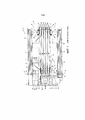
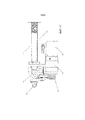
Фиг.1 иллюстрирует предшествующий уровень техники, понижающий привод полиспаста, приводимый в действие системой барабанов, которая содержит углы наклона.1 illustrates the prior art of a chain hoist reduction drive driven by a reel system that includes pitch angles.
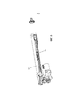
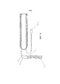
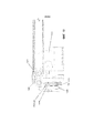
Фиг.2 изображает изометрический вид линейного привода во всей его полноте.Figure 2 is an isometric view of a linear actuator in its entirety.
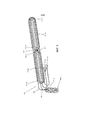
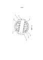
Фиг.3 показывает изометрический вид основных приводных элементов линейного привода с ременной передачей.3 shows an isometric view of the main drive elements of a belt driven linear actuator.
Фиг.4 представляет собой пример иллюстрации соединений выходного штока привода.4 is an example illustration of the actuator output stem connections.
Фиг.5 показывает подробный изометрический вид основных структурных элементов привода.5 shows a detailed isometric view of the main structural elements of the drive.
Фиг.6 представляет изометрический вид топологии отдельного ремня.6 is an isometric view of a single belt topology.
Фигуры 7A-7C представляют собой пример иллюстрации геометрического метода, используемого для предотвращения углов наклона в свободных промежутках полиспаста. Точка наблюдения принимается вдоль главной оси привода.Figures 7A-7C are an example of an illustration of a geometric technique used to prevent tilt angles in free spacing of a chain hoist. The observation point is taken along the main axis of the drive.
Фиг.7D-Фиг.7E иллюстрирует конструкцию машины, которая позволяет избегать углов наклона посредством способов предшествующего уровня техники.FIGS. 7D-7E illustrate a machine design that avoids tilt angles by means of prior art methods.
Фиг.8 изображает осевой вид топологии ремня.8 is an axial view of a belt topology.
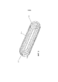
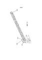
Фиг.9 показывает изометрический вид отдельного полиспаста на основе ремня.Fig. 9 shows an isometric view of a separate chain hoist based on a belt.
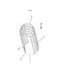
Фиг.10 изображает изометрический вид сечения отдельного полиспаста на основе ремня.10 is an isometric cross-sectional view of a separate chain hoist based on a belt.
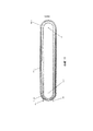
Фиг.11 показывает вид сбоку полиспаста на основе ремня, перпендикулярно оси правостороннего набора шкивов.11 shows a side view of a belt-based pulley block perpendicular to the axis of a right-hand set of pulleys.
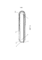
Фиг.12 показывает вид сбоку полиспаста на основе ремня, перпендикулярно оси левостороннего набора шкивовFigure 12 shows a side view of a belt-based chain hoist perpendicular to the axis of a left-hand set of pulleys.
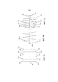
Фиг.13 представляет сечение набора шкивов, которые поддерживают ремень. Точка наблюдения принимается вдоль главной оси привода.13 is a cross-sectional view of a set of pulleys that support a belt. The observation point is taken along the main axis of the drive.
Фиг.14 иллюстрирует вид сбоку топологии ремня рядом с концом двигателя привода.14 illustrates a side view of a belt topology near an end of a drive motor.
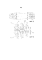
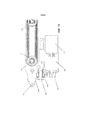
Фиг.15 показывает вид сбоку привода в сечении.15 shows a side cross-sectional view of the actuator.
Фиг.16 представляет собой пример иллюстрации средства окончания концов ремня и механизма поддержки натяжения ремня.Fig. 16 is an illustrative example of a belt end ending means and a belt tensioning support mechanism.
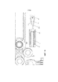
Фиг.17 показывает вид сбоку привода.Fig shows a side view of the drive.
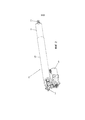
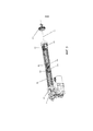
Фиг.18 иллюстрирует отдельные виды изобретения, действующие только на растяжение.FIG. 18 illustrates specific tensile-only views of the invention.
Фиг.19 представляет крупный план рамной структуры из отдельных видов.Fig. 19 is a close-up of a frame structure from selected views.
Фиг.20 показывает заднюю сторону видов только для натяжения по этому изобретению, иллюстрирующую топологию ремня.Fig. 20 shows the rear side of the tension-only views of this invention illustrating the topology of the belt.
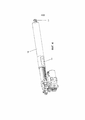
Фиг.21 показывает полный изометрический вид реализации данного изобретения только для натяжения.21 shows a complete isometric view of an implementation of the present invention for tension only.
ПОДРОБНОЕ ОПИСАНИЕ ИЗОБРЕТЕНИЯDETAILED DESCRIPTION OF THE INVENTION
Ниже приведены более подробные описания различных концепций, относящихся к и примерам осуществления, устройству тали для использования с плоским ремнем.The following are more detailed descriptions of various concepts and embodiments of a hoist for use with a flat belt.
Фиг.1 иллюстрирует плоский ремень, используемый в традиционной топологии полиспаста, описанной в патенте США № 8,714,524 В2. Два параллельных вала 76 и 106 содержат множество шкивов, по которым проходит плоский ремень 120. Один конец ремня закреплен на конце 122, тогда как другой конец плоского ремня приводится в движение бобиной 121. Все шкивы свободно вращаются вокруг своих соответствующих валов, за исключением барабана, который приводится в действие двигателем 114. Механическое понижение, наблюдаемое на бобине такой системы, является значительным и эквивалентно количеству свободных промежутков в системе, которое в данном случае составляет 10. Способы полиспаста обычно используются с тросом, а не с плоскими ремнями, из-за углов наклона («перегибов») в ремне, которые могут возникнуть на каждой из границы раздела шкива, вызванных тем, что свободные промежутки 128 являются не горизонтальными. Эта неидеальная геометрическая ситуация приводит либо к асимметричному распределению натяжения внутри армирующих прядей, и/или к скольжению между ремнем и шкивом. Преждевременный выход из строя ремня произойдет из-за истирания боковой стенки и усталости прядей. Система наматывания, которая обрабатывает участки ремня, которые подвергаются наибольшему количеству циклов изгиба, является наиболее вероятной областью для отказа ремня. В этой конструкции присутствуют не только углы наклона, но и они различаются, так как расстояние между основными приводными валами 76 и 106 варьируется в зависимости от диапазона перемещения машины. Хотя эта система может работать в ограниченных условиях, рабочие характеристики ремня, измеряемые общим натяжением, давлением шкива и сроком службы, будут скомпрометированы по сравнению с тросом, который подвергается той же топологии.1 illustrates a flat belt used in a conventional chain hoist topology described in US Pat. No. 8,714,524 B2. The two
Фиг.2 показывает общую форму настоящего изобретения. Привод 201 состоит из внешнего шасси 202, которое может быть выполнено в форме вмещающего корпуса, и приводного вала 203, который вытягивается и втягивается относительно внешнего шасси, которое может быть втянуто по меньшей мере частично во внешнее шасси 202. Элементы 204 и 205 крепления расположены, соответственно, на внешнем шасси и на приводном валу 203, что позволяет подавать питание в эти точки. Привод приводится в действие двигателем 206 (например, электрическим двигателем).2 shows the general form of the present invention. The
Фиг.3 изображает основные рабочие элементы привода 201. Унитарный плоский ремень 301 проходит вокруг четырех основных множеств шкивов 308, 309, 310 и 311, которые соединены с возможностью вращения с четырьмя основными приводными валами 302, 303, 304 и 305. Внешние приводные валы 304 и 305 закреплены относительно шасси 202, в то время как внутренние приводные валы 302 и 303 могут свободно перемещаться вдоль главной оси 307 посредством призматического соединения, создаваемого шасси 202 и ведущим валом 203.3 shows the main operating elements of the
Фиг.4 иллюстрирует структуру, используемую при передаче осевой нагрузки от элементов 205 крепления на внутренние приводные валы 302 и 303. Выходной вал 203 может быть изготовлен в виде полого вала. Выходной вал 203 соединяет элементы 205 крепления с внутренними приводными валами 302 и 303 посредством жестких вставок 402, образующих неподвижный узел компонентов, которые составляют силовую раму.4 illustrates a structure used in transferring the axial load from the
Фиг.5 представляет структуру, связанную с неподвижной рамой. Полукруглые элементы 501, 502 являются компонентами внешнего шасси 202, которые соединяют внешний приводной вал 304 с остальной частью основания шасси. Таким образом, может быть создано натяжение в обоих направлениях между неподвижными валами 304 и 305 и валами 302 и 303 силовой рамы, которые перемещаются относительно неподвижных валов 304 и 305 и относительно внешнего шасси 202 и внутри него.5 shows a structure associated with a fixed frame.
Фиг.6 иллюстрирует топологию ремня в полном объеме. Единое плоское тело 301 ремня начинается с геометрии 601 заклинивания конца, которая близко закреплена относительно внешнего шасси 202. Ремень 301 наматывается на множество шкивов 308, соединенных с возможностью вращения с валом 302, и наматывается на множество шкивов 311, соединенных с возможностью вращения с валом 305, вызывая изогнутые геометрии 602a-e и 604 a-d ремня. Свободные промежутки 603 a-j соединяются с дугообразными участками ремня для того, чтобы полностью составить устройство полиспаста. Затем ремень наматывается на шкив перенаправления для образования дуги 605, которая ведет к узлу привода. Узел привода представляет собой фрикционный приводной компонент, состоящий из фрикционного барабана и противоположного ему направляющего шкива. Несколько участков 606a-c ремня находятся на тяговом барабане 1501, в то время как дополнительные участки 607a, b дуги находятся на направляющем шкиве 1503, который свободно вращается. Выходя из узла привода, дуга 608 ремня обеспечивает перенаправление вдоль промежутка 614 на противоположный полиспаст, где он наматывается вокруг двух множеств шкивов 309 и 310, которые свободно вращаются вокруг валов 303 и 304, соответственно. Они образуют дуговые участки 609 a-f и 611 a-e, соединенные свободными промежутками 610 a-j. Выходя из второго полиспаста, ремень проходит вдоль свободного промежутка 612, который ведет к концевой точке 613 заклинивания.6 illustrates the belt topology in its entirety. The single
В условиях работы, один полиспаст растягивается, в то время как другой сокращается. Разница напряжения между двумя наборами является эквивалентной внешней нагрузке, налагаемой на систему, а разница напряжения ремня от стороны высокого напряжения к стороне низкого напряжения обеспечивается фрикционным приводом, который будет описан позже. Следует отметить, что в этом примере варианта осуществления изобретения два полиспаста противостоят друг другу для обеспечения возможности двунаправленной нагрузки. Другие варианты осуществления изобретения, которые требуют возможности одностороннего действия, могут требовать только одного полиспаста (см. Фиг.18) с избыточным ремнем, который высвобождается из фрикционной передачи, ведомой в приемную бобину низкого напряжения.In working conditions, one pulley block is stretched while the other is being reduced. The voltage difference between the two sets is equivalent to the external load applied to the system, and the belt voltage difference from the high voltage side to the low voltage side is provided by a friction drive, which will be described later. It should be noted that in this exemplary embodiment of the invention, the two pulleys are opposed to each other to allow bi-directional loading. Other embodiments of the invention that require single acting capability may require only one chain hoist (see FIG. 18) with a redundant belt that is released from a friction drive driven into a low voltage take-up reel.
Фигуры 7A-7C представляют собой пример иллюстрации геометрического метода, используемого для предотвращения углов наклона в устройстве полиспаста. На этой фигуре мы смотрим вниз по главной оси движения трех различных видов полиспастов, причем в каждом случае показана центральная линия ремня или троса. Фиг.7А представляет традиционное устройство полиспаста. Фиг.7В представляет модифицированную конструкция полиспаста, которая устраняет углы наклона посредством простого способа наклона. Фиг.7С представляет описанный в данном документе способ геометрического отображения, который учитывает общие оси обоих наборов шкивов, а также устраняет углы наклона. Фиг.7D-Фиг.7Е представляют конструкцию машины, основанную на способе, изображенном на Фиг.7В.Figures 7A-7C are an example illustration of a geometric technique used to prevent tilt angles in a chain hoist device. In this figure, we are looking down the main axis of motion of three different types of chain hoists, each showing the center line of the belt or cable. 7A shows a conventional chain hoist device. 7B shows a modified chain hoist design that eliminates tilt angles through a simple tilt method. 7C is a geometric mapping method described herein that takes into account the common axes of both sets of pulleys and also eliminates tilt angles. FIGS. 7D-7E represent a machine structure based on the method shown in FIG. 7B.
Обычный полиспаст, аналогичный тому, который показан на фиг.1, будет иметь проекцию, аналогичную крайней левой иллюстрации, состоящей из двух наборов шкивов одинакового диаметра, которые расположены на осях 705, которые являются параллельными, и от упомянутого угла проекции будет казаться совпадающей. Первый набор шкивов будет представлять дугообразные участки гибкого растягивающего элемента, которые, если смотреть от проекции упомянутой оси, будут отображаться в виде вертикальных линий 701a, b, c. Следует обратить внимание, что для простоты здесь показаны только шесть свободных промежутков. Второй набор шкивов будет отображать дугообразные участки центральной линии гибкого растягивающего элемента, которые, если смотреть от упомянутого угла проекции, будут отображаться в виде вертикальных линий 702 a, b, c. Свободные промежутки 703 a, b, c проходят от первого набора шкивов ко второму набору шкивов, а свободные промежутки 704 a, b проходят от второго набора шкивов обратно к первому. Эти свободные промежутки, аналогичные свободным промежуткам 128 на фиг.1, являются не параллельными главной оси и, таким образом, имеют поперечную составляющую, которую можно увидеть с этой перспективы. Наличие этой поперечной составляющей свидетельствует об угле наклона, который является очевидным в любой точке входа в шкив.A conventional pulley block like the one shown in Fig. 1 will have a projection similar to the leftmost illustration, consisting of two sets of pulleys of the same diameter, which are located on
Чтобы адаптировать полиспаст для использования с плоским ремнем, мы должны избавиться от углов наклона. Это легко достигается простым наклоном каждого из шкивов и их соответствующих дуг 707a-c ремня согласно фиг.7B и фиг.7D и фиг.7E, так что горизонтальный аспект свободного промежутка сокращается до нуля. У этого вида, все шкивы наклонены на один и тот же угол, так что углы наклона исчезают.To adapt the chain hoist for use with a flat belt, we have to get rid of the tilt angles. This is easily achieved by simply tilting each of the pulleys and their respective belt arcs 707a-c in FIGS. 7B and FIGS. 7D and 7E so that the horizontal aspect of the free space is reduced to zero. In this view, all the pulleys are tilted at the same angle, so the tilt angles disappear.
Противоположный набор шкивов будет создавать проекции 708 а-в линии центров. Это выполняет условие нулевого угла наклона, но делает оси 706 а-с шкивов поворота больше не совпадающими. Таким образом, опорный вал должен иметь несколько не совпадающих участков вала, которые поддерживают шкивы.The opposite set of pulleys will create projections 708 a-in the center line. This satisfies the zero tilt condition, but renders the pivot pulley axes 706 a-c no longer aligned. Thus, the support shaft must have several mismatched shaft sections that support the pulleys.
Фиг.7D и Фиг.7E изображают конструкцию машины, которая основана на этом принципе исключения угла наклона. Как можно видеть, опорные валы (с осевыми линиями 706a-c) не совпадают друг с другом на обоих концах полиспаста. Эта машина, разработанная Роланом Верри и Жаном-Марком Тейсье, испытывает усталость при изгибе в образцах из проволочного троса. Благодаря умелому контролю величины хода некоторые участки троса подвергаются воздействию множества долей максимального количества циклов изгиба. Таким образом, запуская машину только один раз, оператор может определить состояние износа троса при 20%, 40%, 60%, 80% и 100% от максимального количества циклов испытаний на изгиб. В случае этой машины, допустима дополнительная ширина машины, полученная методом исключения углов наклона, и шкивы по необходимости имеют одинаковый размер для целей сопоставимой информации тестирования.FIGS. 7D and 7E depict a machine structure that is based on this tilt exclusion principle. As you can see, the support shafts (with
Настоящее изобретение не требует, чтобы шкивы были точно одинакового размера, и чрезвычайно важно поддерживать общую компактность машины и непрерывность опорных валов.The present invention does not require the pulleys to be exactly the same size, and it is extremely important to maintain the overall compactness of the machine and the continuity of the backup shafts.
Это выполнено на иллюстрации фиг.7С. Геометрия может быть найдена посредством метода отображения, начиная с осей 709 и 710 шкива, которые располагаются на противоположных концах полиспаста. Начальный размер 711a шкива и его положения осевого промежутка сначала вычерчиваются на его оси 710, с каждой последующей дугой осевой линии (712a, затем 711b, 712b, 711c, 712c и т.д.) определяемой его предшественником и его перпендикулярностью и сбалансированностью на своем собственном валу. Существует только одно геометрическое решение для набора шкивов с учетом набора осей 709, 710 шкивов, исходной геометрии 711а дуги осевой линии и количества шкивов для генерации. Результирующие плоские местоположения осевых линий свободного промежутка, как видно из этой перспективы, находятся вдоль окружного профиля 713 с упомянутыми дополнительными ограничениями. Расстояние между параллельными шкивами является обязательно непостоянным и уменьшается по мере уменьшения диаметра шкивов по направлению к периферии.This is done in the illustration of FIG. 7C. The geometry can be found through the display method, starting with the pulley axes 709 and 710, which are located at opposite ends of the chain hoist. The
Фиг.8 показывает осевой вид топологии ремня с выделением оси 801 вращения внешнего вала 305 и его соответствующего набора свободно вращающихся шкивов 311. Участки 604a-d ремня находятся на множестве шкивов 311 в соответствии с положениями, показанными на фиг.7. Множество шкивов 308 свободно вращаются вокруг вала 302 с его осью 802. Участки 602a-e ремня находятся на множестве шкивов 308 в соответствии с положениями, изображенными на фиг.7.FIG. 8 shows an axial view of a belt topology, highlighting the axis of
Фиг.9 показывает изометрический вид топологии полиспаста. Дуговые геометрии 609 a-f и 611 a-e соединены свободными промежутками 610 a-j.9 shows an isometric view of a chain hoist topology.
Фиг.10 показывает сечение топологии полиспаста, включая свободные промежутки 612 и 614, которые приводят к заклиниванию 613 окончания и изгибу 608 перенаправления, соответственно. Окружной профиль 713 изображен, пересекая центральную точку каждого участка ремня в сечении.10 shows a cross-sectional view of a chain hoist topology including
Фиг.11 и фиг.12 представляют вид сбоку топологии полиспаста для ясности.11 and 12 are side views of a chain hoist topology for clarity.
Фиг.13 иллюстрирует сечение множества шкивов 308, которые состоят из пяти отдельных шкивов 1301a-e, каждый из которых вращается с различными скоростями и свободно вращается вокруг вала 303. Шкивы имеют разделительные упорные шайбы 1302 a-f, которые допускают сжимающую осевую нагрузку стопки шкивов. Уплотнения 1303 a-d поддерживают объем смазанного подшипника и исключают возможные загрязнения. Участки 611a-e ремня расположены на множестве шкивов 308. Вставки 402а и 402b выходного штока обеспечивают механическое соединение между валами 302, 303 силовой рамы и выходным штоком 203.13 illustrates a cross-sectional view of a plurality of
Фиг.14 изображает вид сбоку топологии ремня вблизи приводного двигателя для ясности.14 depicts a side view of a belt topology in the vicinity of a drive motor for clarity.
Фиг.15 показывает опорную структуру множества компонентов в сечении. Двигатель 206 и его редуктор 1502 прикреплены к тяговому барабану 1501, который приводит в движение участки 606a-c ремня. Участки 607 а, b ремня постоянно находятся на натяжном барабане 1503, который свободно вращается вокруг своей опорной оси 1505. Базовая рама 1504 закрепляет эти компоненты на месте.15 shows a support structure of a plurality of components in cross section.
Фиг.16 иллюстрирует вид сечения натяжного механизма для концов ремня. Геометрия 613 заклинивания ремня сжата между клином 1601 и опорными стенками 1602а, b. Опорные стенки 1602a, b являются частью оконечного корпуса 1603, который сжимает пружину 1605 сжатия против корпуса 1604 концевой заделки. Направляющий шкив используется для изменения направления ремня от корпуса концевой заделки. Корпус 1604 концевой заделки прикреплен к базовой раме 1504. При нормальной работе, оконечный корпус 1603 сжимается относительно базовой рамы 1504, когда в ремне развивается высокое натяжение. Если во время работы развивается низкое натяжение ремня, пружина 1605 сжатия выталкивает оконечный корпус 1603 наружу, постоянно поддерживая натяжение ремня и обеспечивая, таким образом, работу тягового барабана 1501.16 illustrates a cross-sectional view of a tensioning mechanism for the ends of a belt. The
Фиг.17 иллюстрирует полный вид сбоку многих базовых компонентов для ясности.17 illustrates a full side view of many of the base components for clarity.
Фиг.18 показывает альтернативную разновидность изобретения, которое основывается только на одном наборе полиспаста. Ремень после выхода из первого полиспаста и приводного устройства, наматывается на барабан. Множество шкивов 1801 аналогичны набору 311 шкивов, а множество шкивов 1802 аналогичны набору 310 шкивов. Приводной шкив 1803 аналогичен приводному шкиву 1501 из предыдущего вида, а натяжной шкив 1804 аналогичен натяжному шкиву 1503.FIG. 18 shows an alternative variation of the invention which is based on only one set of chain hoists. The belt, after exiting the first chain hoist and the drive device, is wound on a drum. The plurality of
Фиг.19 представляет детализированный вид элементов привода. Топология ремня остается идентичной первому полиспасту, шкиву перенаправления и приводному узлу. Участки 1901a-c дуги ремня аналогичны участкам 606a-c дуги ремня, а участки 1902a, b дуги ремня аналогичны 607a, b. Когда ремень выходит из области привода, он перенаправляется шкивом 1903 на приемную бобину, а не перенаправляется на противоположный полиспаст. Бобина 1904 может приводиться в действие пружиной или активным механическим средством.19 is a detailed view of the drive elements. The belt topology remains identical to the first chain hoist, redirection pulley and drive assembly. Belt arch sections 1901a-c are similar to belt arch sections 606a-c, and belt arch sections 1902a, b are similar to 607a, b. When the belt exits the drive area, it is redirected by the 1903 pulley to the take-up reel instead of being redirected to the opposite chain hoist. Bobbin 1904 can be spring-driven or powered by an active mechanical means.
Фиг.20 представляет детализированный вид топологии ремня второй разновидности по изобретению. Участок 2001 дуги ремня расположен на шкиве перенаправления 1903 со свободным промежутком 2002, ведущим к намотанному ремню 2003.Fig. 20 is a detailed topology view of a belt of a second variation according to the invention. Belt
Фиг.21 показывает изометрический вид второй разновидности.21 shows an isometric view of a second variation.
Свободные промежутки 2100a-j поддерживают растягивающую нагрузку через привод, аналогично любому другому полиспасту на основе подъемных устройств. Ремень приводится в движение через ведущий вал приводного узла на основе трения, состоящего из приводного шкива 1803 и натяжного шкива 1804. После выхода из узла привода, ремень 1903 перенаправляется на барабан 1904 для хранения при низком натяжении. Большая часть потока мощности через систему проходит через ведущий вал приводного шкива 1803 и во вращательный привод.The clearances 2100a-j support the tensile load through the drive in a manner similar to any other hoist-based chain hoist. The belt is driven through the drive shaft of a friction driven drive assembly consisting of
Используемые здесь термины «приблизительно», «примерно», «по существу» и аналогичные термины предназначены для того, чтобы иметь широкое значение в гармонии с общим и общепринятым использованием специалистами в данной области техники, к которой относится данный предмет изобретения.As used herein, the terms "about," "about," "substantially," and similar terms are intended to have a broad meaning in harmony with the general and customary use of those skilled in the art to which this subject matter pertains.
Специалистам в данной области техники, которые рассматривают это изобретение, следует понимать, что эти термины предназначены для того, чтобы обеспечить описание определенных описанных признаков, не ограничивая объем этих признаков предоставленными точными числовыми диапазонами.Those of skill in the art who consider this invention should understand that these terms are intended to provide a description of certain features described without limiting the scope of those features to the precise numerical ranges provided.
Соответственно, эти термины следует интерпретировать как указывающие на то, что несущественные или незначительные модификации или изменения описанного предмета и считаются находящимися в рамках объема изобретения.Accordingly, these terms are to be interpreted as indicating that minor or minor modifications or changes to the subject matter described and are considered to be within the scope of the invention.
Следует отметить, что термин «пример осуществления», используемый в данном документе для описания различных вариантов осуществления, предназначен для указания того, что такие варианты осуществления являются возможными примерами, представлениями и/или иллюстрациями возможных вариантов осуществления (и такой термин не предназначен для обозначения того, что такие варианты осуществления являются обязательно неординарными или превосходными примерами).It should be noted that the term “exemplary embodiment” as used herein to describe various embodiments is intended to indicate that such embodiments are possible examples, representations, and / or illustrations of possible embodiments (and such a term is not intended to indicate that that such embodiments are necessarily extraordinary or excellent examples).
Для цели настоящего изобретения, термин «связанный» означает соединение двух элементов прямо или косвенно друг с другом. Такое соединение может быть неподвижным или подвижным по природе. Такое соединение может быть достигнуто двумя элементами или двух элементов, и любые дополнительные промежуточные элементы, в целом, образованы как единое цельное тело друг с другом или с двумя элементами или двумя элементами и любыми дополнительными промежуточными элементами, прикрепленными друг к другу. Такое соединение может быть постоянным по природе или может быть съемным или высвобождаемым по природе.For the purpose of the present invention, the term "linked" means the connection of two elements directly or indirectly to each other. Such a connection can be stationary or mobile in nature. Such connection can be achieved with two elements or two elements, and any additional intermediate elements, in general, formed as a single one-piece body with each other or with two elements or two elements and any additional intermediate elements attached to each other. Such a connection may be permanent in nature, or may be removable or releasable in nature.
Следует отметить, что ориентация различных элементов может отличаться в соответствии с другими примерами осуществления, и что такие варианты предназначены для охвата настоящим изобретением.It should be noted that the orientation of the various elements may differ in accordance with other embodiments, and that such variations are intended to be encompassed by the present invention.
Следует понимать, что признаки раскрытых вариантов осуществления могут быть включены в другие раскрытые варианты осуществления.It should be understood that the features of the disclosed embodiments may be included in other disclosed embodiments.
Следует отметить, что конструкции и устройства пружинных систем или их компонентов, как показано в различных примерах осуществления, являются только иллюстративными.It should be noted that the structures and arrangements of the spring systems or their components as shown in the various embodiments are illustrative only.
Хотя только несколько вариантов осуществления были подробно описаны в этом раскрытии, специалисты в данной области техники, которые рассматривают это изобретение, легко поймут, что возможны многие модификации (например, изменения в габаритах, размерах, структурах, формах и пропорциях различных элементов, значениях параметров, схемах расположения, использования материалов, цветов, ориентации и т.д.) без существенного отклонения от новых учений и преимуществ раскрытого предмета.Although only a few embodiments have been described in detail in this disclosure, those skilled in the art who contemplate this invention will readily understand that many modifications are possible (e.g., changes in dimensions, dimensions, structures, shapes and proportions of various elements, parameter values, layouts, use of materials, colors, orientation, etc.) without significantly deviating from the new teachings and benefits of the disclosed subject.
Например, элементы, показанные как образованные как одно целое, могут быть составлены из нескольких частей или элементов, положение элементов может быть обращено или изменено иным образом, и природа или количество дискретных элементов или положений могут быть изменены или отличаться.For example, elements shown as being formed as a whole can be composed of multiple parts or elements, the position of the elements can be reversed or otherwise changed, and the nature or number of discrete elements or positions can be changed or different.
Порядок или последовательность любых этапов процесса или способа могут изменяться или повторно чередоваться согласно альтернативным вариантам осуществления. Другие замены, модификации, изменения и пропуски также могут быть сделаны в конструкции, рабочих условиях и компоновке различных примеров осуществления без отклонения от объема настоящего изобретения.The order or sequence of any steps in a process or method may be varied or re-interleaved according to alternative embodiments. Other substitutions, modifications, changes and omissions can also be made in the design, operating conditions and layout of the various embodiments without departing from the scope of the present invention.
Вся литература и аналогичные материалы, цитируемые в этой заявке, включая, но не ограничиваясь этим, патенты, патентные заявки, статьи, книги, трактаты и веб-страницы, независимо от формата такой литературы и аналогичных материалов, прямо включены путем ссылки в их полноте.All literature and similar materials cited in this application, including, but not limited to, patents, patent applications, articles, books, treatises and web pages, regardless of the format of such literature and similar materials, are expressly incorporated by reference in their entirety.
В случае если одна или несколько из включенной литературы и аналогичных материалов отличаются от или противоречат этой заявке, включая, но, не ограничиваясь определенными терминами, условием использования, описаниями способов или тому подобным, эта заявка контролируется.In the event that one or more of the included literature and similar materials differ from or contradict this application, including, but not limited to certain terms, conditions of use, method descriptions or the like, this application is controlled.
Хотя в материалах настоящей заявки было раскрыто и проиллюстрировано множество обладающих признаками изобретения различных вариантов осуществления, специалистам в данной области техники будет абсолютно очевидно широкое разнообразие других средств и/или конструкций для выполнения функций и/или для получения результатов и/или одного или более преимуществ, описанных в материалах настоящей заявки, при этом каждое из таких изменений и/или модификаций полагается как находящееся в пределах объема обладающих признаками изобретения вариантов осуществления, описанных в материалах настоящей заявки.While many different inventive embodiments have been disclosed and illustrated herein, those skilled in the art will readily appreciate a wide variety of other means and / or designs for performing functions and / or for obtaining results and / or one or more advantages. described in the materials of this application, each of such changes and / or modifications is considered to be within the scope of the inventive embodiments described in the materials of this application.
В более общем смысле специалисты в данной области техники без труда осознают, что все параметры, размеры, материалы и конфигурации, описанные в материалах настоящей заявки, подразумеваются в качестве примерных, и что фактические параметры, размеры, материалы и/или конфигурации будут зависеть от специфичного применения, для которого эти обладающие признаками изобретения идеи используются.More generally, those skilled in the art will readily understand that all parameters, dimensions, materials and configurations described in the materials of this application are intended as exemplary, and that the actual parameters, dimensions, materials and / or configurations will depend on the specific the application for which these inventive ideas are used.
Специалисты в данной области техники осознают или будут в состоянии определить, используя накопленный опыт, множество эквивалентов для отдельных обладающих признаками изобретения вариантов осуществления, описанных в материалах настоящей заявки.Those of skill in the art will recognize, or will be able to determine, through experience, many equivalents for the individual inventive embodiments described herein.
Следовательно, следует понимать, что упомянутые выше варианты осуществления представлены лишь в качестве примера, и что на практике могут быть применены отличные от описанных и заявленных варианты осуществления, обладающие признаками изобретения, находящиеся в пределах объема прилагаемой формулы изобретения и ее эквивалентов.Therefore, it should be understood that the above-mentioned embodiments are presented by way of example only, and that other than those described and claimed, embodiments having the features of the invention, falling within the scope of the appended claims and their equivalents, may be practiced.
Обладающие признаками изобретения варианты осуществления настоящего изобретения направлены к каждому индивидуальному признаку, системе, изделию, материалу, комплекту и/или способу, описанному в материалах настоящей заявки.Inventive embodiments of the present invention are directed to each individual feature, system, article, material, kit, and / or method described herein.
Также любое сочетание двух или более таких признаков, систем, изделий, материалов, комплектов и/или способов, если такие признаки, системы, изделия, материалы, комплекты и/или способы не являются взаимно исключающими, включено в пределы обладающего признаками изобретения объема настоящего изобретения.Also, any combination of two or more such features, systems, products, materials, kits and / or methods, unless such features, systems, products, materials, kits and / or methods are mutually exclusive, is included within the inventive scope of the present invention. ...
Кроме того, способ, описанный в данном документе, может быть воплощен как способ, из которого был предоставлен по меньшей мере один пример.In addition, the method described herein may be embodied as a method from which at least one example has been provided.
Действия, выполняемые как часть способа, могут быть упорядочены любым подходящим образом.The actions performed as part of the method can be ordered in any suitable manner.
Соответственно, могут быть созданы варианты осуществления, в которых действия выполняются в порядке, отличном от проиллюстрированного, что может включать в себя выполнение некоторых действий одновременно, даже если они показаны как последовательные действия в иллюстративных вариантах осуществления.Accordingly, embodiments may be created in which actions are performed in an order other than that illustrated, which may include performing some actions at the same time even though they are shown as sequential actions in illustrative embodiments.
Все определения, которые даны и использованы в материалах настоящей заявки, должны быть приняты как более преимущественные, чем определения словарей, определения документов, включенных посредством ссылки, и/или обычные значения данных терминов.All definitions that are given and used in the materials of this application should be taken as more preferential than definitions of dictionaries, definitions of documents incorporated by reference, and / or the usual meanings of these terms.
Единственное число существительных, использованных в описании настоящей заявки и в формуле изобретения, если четко не указано иным образом, должно пониматься как «по меньшей мере, один».The singular number of nouns used in the description of the present application and in the claims, unless clearly indicated otherwise, should be understood as "at least one".
Фраза «и/или» как указано в описании настоящей заявки, должна подразумеваться как «любой из двух или оба вместе» для соединяемых таким образом элементов, т.е. эти элементы в некоторых случаях присутствуют в этом объединении, а в других случаях - отсутствуют.The phrase "and / or" as indicated in the description of the present application should be understood as "either of the two or both together" for the elements so connected, i. E. these elements are in some cases present in this union, and in other cases they are absent.
Множество элементов, перечисленных с помощью «и/или» должно истолковываться подобным образом, т.е. «один или более» из элементов, соединяемых подобным образом.Many of the items listed with "and / or" are to be construed in a similar way, i.e. "One or more" of elements that are connected in a similar way.
Если необходимо могут быть использованы другие элементы, отличные от элементов в частности перечисленных союзом «и/или», относящиеся или не относящиеся к перечисленным в частности элементам.If necessary, other elements can be used, other than those specifically listed by the union "and / or", whether or not related to the specifically listed elements.
Таким образом, в качестве неограничивающего примера, ссылка на «A и/или B», когда используется в связи со свободным языком, таким как «содержащий», может ссылаться, в одном варианте осуществления, только на A (необязательно, включая элементы, отличные от В); в другом варианте осуществления только к B (необязательно включая элементы, отличные от A); в еще одном варианте осуществления к A и B (необязательно включая другие элементы); и т.п.Thus, as a non-limiting example, a reference to "A and / or B", when used in connection with a free language such as "comprising", may refer, in one embodiment, only to A (optionally, including elements other than from B); in another embodiment only to B (optionally including elements other than A); in yet another embodiment to A and B (optionally including other elements); etc.
Используемый здесь в описании и формуле изобретения термин «или» следует понимать как имеющий то же значение, что и «и/или», как определено выше.As used herein in the specification and claims, the term “or” is to be understood as having the same meaning as “and / or” as defined above.
Например, при разделении элементов в списке «или» или «и/или» должны интерпретироваться как включающие, то есть включающие по меньшей мере один, но также включающие более одного, из числа или списка элементов, и, возможно, дополнительные незарегистрированные позиции.For example, when dividing items in a list, “or” or “and / or” should be interpreted as including, that is, including at least one, but also including more than one, from a number or list of items, and possibly additional unregistered items.
Только термины, четко обозначенные как противоположные, такие как «только один из» или «точно один из», или, когда используется в формуле изобретения «состоящий из», будут относиться к включению ровно одного элемента из числа или списка элементов.Only terms clearly indicated as opposed, such as "only one of" or "exactly one of", or when used in the claims "consisting of", will refer to the inclusion of exactly one item from a number or list of items.
Как правило, термин «или», используемый в данном документе, должен толковаться только как указывающий на исключительные альтернативы (т.е. «один или другой, но не оба»), когда ему предшествуют термины исключительности, такие как «либо», «один из», «только одно из» или «точно одно из», «состоящее, по существу, из» при использовании в формуле изобретения, имеет свое обычное значение, используемое в области патентного права.In general, the term “or” as used in this document should only be construed as indicating exclusive alternatives (ie, “one or the other, but not both”) when preceded by exclusivity terms such as “either”, “ one of "," only one of "or" exactly one of "," consisting essentially of "when used in the claims, has its usual meaning as used in the field of patent law.
При использовании в описании настоящей заявки и в формуле изобретения фраза «по меньшей мере, один» со ссылкой к списку из одного или более элементов должна означать по меньшей мере один элемент из одного или более элементов в списке элементов, причем не обязательно включать по меньшей мере каждый элемент, перечисленный в пределах списка элементов, причем не исключаются любые сочетания элементов в списке элементов.When used in the description of the present application and in the claims, the phrase "at least one" with reference to a list of one or more elements shall mean at least one element of one or more elements in the list of elements, and it is not necessary to include at least each element listed within the list of elements, and any combination of elements in the list of elements is not excluded.
Это определение также допускает присутствие, если необходимо, других элементов, отличных от элементов, в частности идентифицированных в пределах списка элементов, к которым ссылается фраза «по меньшей мере, один», при этом они могут быть связанными или несвязанными с идентифицированными в частности элементами.This definition also allows for the presence, if necessary, of other elements other than elements, in particular those identified within the list of elements referred to by the phrase “at least one”, which may or may not be associated with the specifically identified elements.
Таким образом, в качестве не ограничивающего примера выражение «по меньшей мере, один из А и В» (или, эквивалентно, «по меньшей мере, один из А или В», или эквивалентно, «по меньшей мере, один из А и/или В») может ссылаться в одном варианте, по меньшей мере к одному А, если необходимо, включающему больше одного, при отсутствии B (и, если необходимо, включающему элементы отличные от B); в другом варианте по меньшей мере к одному В, если необходимо, включающему больше одного, при отсутствии А (и, если необходимо, включающему элементы отличные от А); еще в одном варианте по меньшей мере к одному А, если необходимо, включающему больше одного, и, по меньшей мере к одному В, если необходимо, включающему больше одного (и, если необходимо, включающему другие элементы); и т.д.Thus, by way of non-limiting example, the expression “at least one of A and B” (or, equivalently, “at least one of A or B”, or equivalently, “at least one of A and / or B ") can refer, in one embodiment, to at least one A, if necessary, including more than one, in the absence of B (and, if necessary, including elements other than B); in another embodiment, at least one B, if necessary, including more than one, in the absence of A (and, if necessary, including elements other than A); in yet another embodiment, at least one A, if necessary, including more than one, and at least one B, if necessary, including more than one (and, if necessary, including other elements); etc.
В формуле изобретения, а также в приведенном выше описании все переходные фразы, такие как «содержащий», «включающий», «несущий», «имеющий», «содержащий в себе», «включающий в себя», «несущий», «составленный из», и тому подобное следует понимать как открытый, то есть означать включающий, но не ограничивающийся им.In the claims, as well as in the above description, all transitional phrases such as “comprising”, “including”, “bearing”, “having”, “containing”, “including”, “bearing”, “composed from ”, and the like should be understood as open, that is, to mean including, but not limited to.
Только переходные фразы «состоящий из» и «состоящий, по существу, из» должны быть закрытыми или полузакрытыми переходными фразами, соответственно, как указано в Руководстве по процедурам патентной экспертизы Патентного ведомства США, раздел 2111.03.Only transitional phrases “consisting of” and “consisting essentially of” shall be closed or semi-closed transitional phrases, respectively, as specified in the US Patent Office Patent Examination Procedures Manual, Section 2111.03.
Формула изобретения не должна рассматриваться как ограниченная описанным порядком или элементами, если не указано иное.The claims are not to be construed as limited to the order or elements described, unless otherwise indicated.
Следует понимать, что специалистом в данной области техники могут быть сделаны различные изменения в форме и деталях, не выходя за рамки сущности и объема прилагаемой формулы изобретения.It should be understood that various changes in form and detail may be made by one skilled in the art without departing from the spirit and scope of the appended claims.
Заявлены все варианты осуществления, которые соответствуют сущности и объему следующей формулы изобретения и ее эквивалентам.All embodiments are claimed which fall within the spirit and scope of the following claims and their equivalents.
Claims (44)
Applications Claiming Priority (3)
| Application Number | Priority Date | Filing Date | Title |
|---|---|---|---|
| US201762555944P | 2017-09-08 | 2017-09-08 | |
| US62/555,944 | 2017-09-08 | ||
| PCT/US2018/050257 WO2019051407A1 (en) | 2017-09-08 | 2018-09-10 | High reduction belt-driven linear actuator |
Related Child Applications (1)
| Application Number | Title | Priority Date | Filing Date |
|---|---|---|---|
| RU2021134553A Division RU2021134553A (en) | 2017-09-08 | 2018-09-10 | HIGH DROP BELT DRIVE LINEAR ACTUATOR |
Publications (3)
| Publication Number | Publication Date |
|---|---|
| RU2020113011A RU2020113011A (en) | 2021-10-08 |
| RU2020113011A3 RU2020113011A3 (en) | 2021-10-08 |
| RU2760776C2 true RU2760776C2 (en) | 2021-11-30 |
Family
ID=65635138
Family Applications (2)
| Application Number | Title | Priority Date | Filing Date |
|---|---|---|---|
| RU2020113011A RU2760776C2 (en) | 2017-09-08 | 2018-09-10 | Linear belt drive with high reduction |
| RU2021134553A RU2021134553A (en) | 2017-09-08 | 2018-09-10 | HIGH DROP BELT DRIVE LINEAR ACTUATOR |
Family Applications After (1)
| Application Number | Title | Priority Date | Filing Date |
|---|---|---|---|
| RU2021134553A RU2021134553A (en) | 2017-09-08 | 2018-09-10 | HIGH DROP BELT DRIVE LINEAR ACTUATOR |
Country Status (23)
| Country | Link |
|---|---|
| US (2) | US11255416B2 (en) |
| EP (2) | EP3679275B1 (en) |
| JP (2) | JP7224342B2 (en) |
| KR (1) | KR102609390B1 (en) |
| CN (2) | CN117028506A (en) |
| AU (1) | AU2018329195B2 (en) |
| BR (1) | BR112020003651A2 (en) |
| CA (1) | CA3073074A1 (en) |
| CL (2) | CL2020000522A1 (en) |
| DK (1) | DK3679275T3 (en) |
| ES (1) | ES2937014T3 (en) |
| FI (1) | FI3679275T3 (en) |
| IL (1) | IL272660B2 (en) |
| LT (1) | LT3679275T (en) |
| MX (1) | MX2020002613A (en) |
| PE (1) | PE20201272A1 (en) |
| PL (1) | PL3679275T3 (en) |
| PT (1) | PT3679275T (en) |
| RU (2) | RU2760776C2 (en) |
| SI (1) | SI3679275T1 (en) |
| UA (1) | UA126081C2 (en) |
| WO (1) | WO2019051407A1 (en) |
| ZA (1) | ZA202001088B (en) |
Families Citing this family (5)
| Publication number | Priority date | Publication date | Assignee | Title |
|---|---|---|---|---|
| CA3073074A1 (en) | 2017-09-08 | 2019-03-14 | Liftwave, Inc. Dba Rise Robotics | High reduction belt-driven linear actuator |
| CN116745230A (en) * | 2020-12-23 | 2023-09-12 | 里弗特威弗股份有限公司以莱斯机器人名义营业 | Self-rolling strip driving mechanism |
| AU2021410706A1 (en) * | 2020-12-23 | 2023-06-15 | Liftwave, Inc. Dba Rise Robotics | Self-reeling belt drive mechanism |
| US11746860B2 (en) * | 2020-12-23 | 2023-09-05 | Liftwave, Inc. | Self-reeling belt drive |
| EP4337591A1 (en) * | 2021-05-10 | 2024-03-20 | Liftwave Inc. Dba Rise Robotics | Flexible form factor belt driven block and tackle |
Citations (4)
| Publication number | Priority date | Publication date | Assignee | Title |
|---|---|---|---|---|
| US3044312A (en) * | 1960-05-20 | 1962-07-17 | Curtiss Wright Corp | Mechanism for converting rotary to linear movement |
| WO2006008515A2 (en) * | 2004-07-20 | 2006-01-26 | Timothy John Jones | Drive belt actuator with drive pulleys of different circumferential speed |
| RU2336450C1 (en) * | 2007-05-04 | 2008-10-20 | Дмитрий Александрович Иосселиани | Friction-type direction converter |
| RU2604762C2 (en) * | 2012-08-22 | 2016-12-10 | Таль | Linear drive |
Family Cites Families (22)
| Publication number | Priority date | Publication date | Assignee | Title |
|---|---|---|---|---|
| US217119A (en) * | 1879-07-01 | Improvement in draft-equalizers | ||
| US222742A (en) * | 1879-12-16 | Improvement in speed-accelerators | ||
| US4272997A (en) | 1978-08-17 | 1981-06-16 | H. A. Phillips & Co. | Drive mechanism |
| JPH0284045A (en) | 1988-09-19 | 1990-03-26 | Hitachi Ltd | Three-phase brushless motor |
| JPH0284045U (en) * | 1988-12-19 | 1990-06-29 | ||
| JPH02199345A (en) * | 1989-01-30 | 1990-08-07 | Canon Inc | Rectilinearly moving device |
| FR2643963B1 (en) * | 1989-03-03 | 1991-06-14 | Noirot Yves | DEVICE FOR DRIVING A FLEXIBLE LINK |
| DE4342500C2 (en) * | 1993-12-07 | 1998-08-06 | Cybertron Gmbh | Device for converting a rotary movement into a linear movement |
| SE505961C2 (en) * | 1994-05-11 | 1997-10-27 | Linvent Ab | Linear conveyor drive mechanism |
| US6134978A (en) * | 1997-11-13 | 2000-10-24 | Lin; Bob | Transmission mechanism for a scanner |
| RU2219224C2 (en) | 1999-12-28 | 2003-12-20 | Панин Александр Андреевич | Multifunctional lubrication composition additive |
| JP2001241525A (en) | 2000-02-25 | 2001-09-07 | Fuminori Hirose | Linear movement device |
| DE102009001667A1 (en) * | 2008-04-11 | 2009-10-15 | Saia-Burgess Murten Ag | Actuator for use in e.g. motor vehicle, has housing parts movable relative to each other, and drawing units e.g. cables, chain or belts, provided for transmission of motor movement to one housing part |
| US8714524B2 (en) | 2009-12-16 | 2014-05-06 | Herkules Equipment Corporation | Belt-driven transportation system |
| FR3002403A3 (en) * | 2013-02-18 | 2014-08-22 | Concept Immo Global | Remotely guided viewing device for allowing interlocutors equipped with connected multimedia terminals to exchange virtual visits of e.g. real estate projects, has viewing module and communication module that are used simultaneously |
| US9121481B2 (en) * | 2013-07-25 | 2015-09-01 | Liftwave, Inc. | Differential conical drive |
| TWI598525B (en) * | 2013-11-01 | 2017-09-11 | 山葉發動機股份有限公司 | Actuator |
| JP2015124528A (en) * | 2013-12-26 | 2015-07-06 | アイシン精機株式会社 | Driving device |
| WO2017004511A2 (en) | 2015-07-02 | 2017-01-05 | Liftwave, Inc. Dba Rise Robotics | Bi-directionally acting differential drive apparatuses, systems, and methods |
| JP6030254B1 (en) * | 2016-01-25 | 2016-11-24 | 上銀科技股▲分▼有限公司 | Belt-type linear transmission module |
| CA3069516A1 (en) | 2017-07-10 | 2019-01-17 | Liftwave, Inc. Dba Rise Robotics | Normalizing tension distribution and minimizing sidewall abrasion within angular drive belt systems |
| CA3073074A1 (en) | 2017-09-08 | 2019-03-14 | Liftwave, Inc. Dba Rise Robotics | High reduction belt-driven linear actuator |
-
2018
- 2018-09-10 CA CA3073074A patent/CA3073074A1/en active Pending
- 2018-09-10 RU RU2020113011A patent/RU2760776C2/en active
- 2018-09-10 KR KR1020207006412A patent/KR102609390B1/en active IP Right Grant
- 2018-09-10 SI SI201830830T patent/SI3679275T1/en unknown
- 2018-09-10 BR BR112020003651-0A patent/BR112020003651A2/en unknown
- 2018-09-10 PE PE2020000325A patent/PE20201272A1/en unknown
- 2018-09-10 CN CN202311171336.XA patent/CN117028506A/en active Pending
- 2018-09-10 DK DK18854618.8T patent/DK3679275T3/en active
- 2018-09-10 WO PCT/US2018/050257 patent/WO2019051407A1/en unknown
- 2018-09-10 US US16/645,018 patent/US11255416B2/en active Active
- 2018-09-10 MX MX2020002613A patent/MX2020002613A/en unknown
- 2018-09-10 EP EP18854618.8A patent/EP3679275B1/en active Active
- 2018-09-10 PL PL18854618.8T patent/PL3679275T3/en unknown
- 2018-09-10 RU RU2021134553A patent/RU2021134553A/en unknown
- 2018-09-10 EP EP22204742.5A patent/EP4194715A3/en active Pending
- 2018-09-10 JP JP2020513759A patent/JP7224342B2/en active Active
- 2018-09-10 ES ES18854618T patent/ES2937014T3/en active Active
- 2018-09-10 UA UAA202002262A patent/UA126081C2/en unknown
- 2018-09-10 LT LTEPPCT/US2018/050257T patent/LT3679275T/en unknown
- 2018-09-10 PT PT188546188T patent/PT3679275T/en unknown
- 2018-09-10 CN CN201880058331.7A patent/CN111133229B/en active Active
- 2018-09-10 FI FIEP18854618.8T patent/FI3679275T3/en active
- 2018-09-10 AU AU2018329195A patent/AU2018329195B2/en active Active
- 2018-09-10 IL IL272660A patent/IL272660B2/en unknown
-
2020
- 2020-02-20 ZA ZA2020/01088A patent/ZA202001088B/en unknown
- 2020-03-03 CL CL2020000522A patent/CL2020000522A1/en unknown
-
2021
- 2021-01-21 CL CL2021000168A patent/CL2021000168A1/en unknown
- 2021-12-27 US US17/562,099 patent/US11920659B2/en active Active
-
2023
- 2023-02-07 JP JP2023016722A patent/JP2023065404A/en active Pending
Patent Citations (4)
| Publication number | Priority date | Publication date | Assignee | Title |
|---|---|---|---|---|
| US3044312A (en) * | 1960-05-20 | 1962-07-17 | Curtiss Wright Corp | Mechanism for converting rotary to linear movement |
| WO2006008515A2 (en) * | 2004-07-20 | 2006-01-26 | Timothy John Jones | Drive belt actuator with drive pulleys of different circumferential speed |
| RU2336450C1 (en) * | 2007-05-04 | 2008-10-20 | Дмитрий Александрович Иосселиани | Friction-type direction converter |
| RU2604762C2 (en) * | 2012-08-22 | 2016-12-10 | Таль | Linear drive |
Also Published As
Similar Documents
| Publication | Publication Date | Title |
|---|---|---|
| RU2760776C2 (en) | Linear belt drive with high reduction | |
| CN1130487C (en) | Synthetic fibre rope driven by rope wheel | |
| AU756246B2 (en) | Stranded synthetic fiber rope | |
| JP4832714B2 (en) | Synthetic fiber rope for power transmission with reinforcing elements and frictionally engaged, and synthetic fiber rope for power transmission with reinforcing elements and positively engaged | |
| JP2011116567A (en) | Tension member for an elevator | |
| BR9916369B1 (en) | tension element for an elevator. | |
| ES2567717T3 (en) | Lathe apparatus | |
| PL195002B1 (en) | Conveying rope made of synthetic fibre | |
| KR20050106471A (en) | Sheave for elevator | |
| US9663328B2 (en) | Elevator system belt | |
| ES2285850T3 (en) | ELEVATOR SYSTEM THAT HAS THE DRIVE MOTOR LOCATED IN THE BOTTOM OF THE ELEVATOR BOX. | |
| KR102520029B1 (en) | Termination for elevator belt | |
| JP2006335567A (en) | Support means with mechanically positive connection for connecting several cables | |
| US20180179023A1 (en) | Increased traction of elevator system belt | |
| US20130270044A1 (en) | Elevator suspension and/or driving arrangement | |
| US20210301907A1 (en) | Linear Motion Device | |
| PT1056675E (en) | Elevator system having drive motor located between elevator car and hoistway sidewall |