RU2760503C1 - Linear part with combined interferometers for a fiber-optic security detector - Google Patents
Linear part with combined interferometers for a fiber-optic security detector Download PDFInfo
- Publication number
- RU2760503C1 RU2760503C1 RU2020131673A RU2020131673A RU2760503C1 RU 2760503 C1 RU2760503 C1 RU 2760503C1 RU 2020131673 A RU2020131673 A RU 2020131673A RU 2020131673 A RU2020131673 A RU 2020131673A RU 2760503 C1 RU2760503 C1 RU 2760503C1
- Authority
- RU
- Russia
- Prior art keywords
- fiber
- optical
- optic
- optionally
- detector
- Prior art date
Links
- 230000003287 optical effect Effects 0.000 claims abstract description 656
- 239000013307 optical fiber Substances 0.000 claims abstract description 199
- 230000035945 sensitivity Effects 0.000 claims abstract description 65
- 230000010363 phase shift Effects 0.000 claims abstract description 40
- 230000000694 effects Effects 0.000 claims abstract description 20
- 239000000523 sample Substances 0.000 claims description 157
- 230000008878 coupling Effects 0.000 claims description 87
- 238000010168 coupling process Methods 0.000 claims description 87
- 238000005859 coupling reaction Methods 0.000 claims description 87
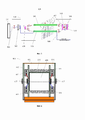
- 230000008859 change Effects 0.000 claims description 85
- 230000000704 physical effect Effects 0.000 claims description 20
- 238000000926 separation method Methods 0.000 claims description 12
- 230000007423 decrease Effects 0.000 claims description 8
- 239000000126 substance Substances 0.000 abstract 1
- 239000000835 fiber Substances 0.000 description 153
- 238000000034 method Methods 0.000 description 81
- 238000000253 optical time-domain reflectometry Methods 0.000 description 26
- 230000011664 signaling Effects 0.000 description 26
- 230000005855 radiation Effects 0.000 description 24
- 238000005253 cladding Methods 0.000 description 20
- 230000002452 interceptive effect Effects 0.000 description 20
- 230000004888 barrier function Effects 0.000 description 19
- 238000001514 detection method Methods 0.000 description 16
- 238000009434 installation Methods 0.000 description 16
- 238000012937 correction Methods 0.000 description 13
- 238000013461 design Methods 0.000 description 12
- 230000005489 elastic deformation Effects 0.000 description 11
- 230000015572 biosynthetic process Effects 0.000 description 8
- 230000000670 limiting effect Effects 0.000 description 8
- 239000002689 soil Substances 0.000 description 8
- 238000004804 winding Methods 0.000 description 8
- 238000010586 diagram Methods 0.000 description 7
- 238000005516 engineering process Methods 0.000 description 7
- 239000004744 fabric Substances 0.000 description 7
- 230000036541 health Effects 0.000 description 7
- 238000004519 manufacturing process Methods 0.000 description 6
- 239000000463 material Substances 0.000 description 6
- 238000000691 measurement method Methods 0.000 description 6
- 239000007787 solid Substances 0.000 description 6
- 230000003068 static effect Effects 0.000 description 6
- XLYOFNOQVPJJNP-UHFFFAOYSA-N water Substances O XLYOFNOQVPJJNP-UHFFFAOYSA-N 0.000 description 6
- 230000003321 amplification Effects 0.000 description 5
- 238000009933 burial Methods 0.000 description 5
- 239000000203 mixture Substances 0.000 description 5
- 238000003199 nucleic acid amplification method Methods 0.000 description 5
- 230000008520 organization Effects 0.000 description 5
- 230000004044 response Effects 0.000 description 5
- 238000005452 bending Methods 0.000 description 4
- 230000008901 benefit Effects 0.000 description 4
- 239000004567 concrete Substances 0.000 description 4
- 230000001419 dependent effect Effects 0.000 description 4
- 238000005259 measurement Methods 0.000 description 4
- 230000001105 regulatory effect Effects 0.000 description 4
- 230000002441 reversible effect Effects 0.000 description 4
- 230000006835 compression Effects 0.000 description 3
- 238000007906 compression Methods 0.000 description 3
- 239000002360 explosive Substances 0.000 description 3
- 230000010365 information processing Effects 0.000 description 3
- 239000002184 metal Substances 0.000 description 3
- 230000004048 modification Effects 0.000 description 3
- 238000012986 modification Methods 0.000 description 3
- 238000012544 monitoring process Methods 0.000 description 3
- 230000008569 process Effects 0.000 description 3
- 239000010865 sewage Substances 0.000 description 3
- 206010011878 Deafness Diseases 0.000 description 2
- 230000005540 biological transmission Effects 0.000 description 2
- 230000000903 blocking effect Effects 0.000 description 2
- 230000001427 coherent effect Effects 0.000 description 2
- 238000010276 construction Methods 0.000 description 2
- 230000006378 damage Effects 0.000 description 2
- 230000003247 decreasing effect Effects 0.000 description 2
- 239000000428 dust Substances 0.000 description 2
- 238000011900 installation process Methods 0.000 description 2
- 230000007246 mechanism Effects 0.000 description 2
- 230000001681 protective effect Effects 0.000 description 2
- 239000000243 solution Substances 0.000 description 2
- RLLPVAHGXHCWKJ-IEBWSBKVSA-N (3-phenoxyphenyl)methyl (1s,3s)-3-(2,2-dichloroethenyl)-2,2-dimethylcyclopropane-1-carboxylate Chemical compound CC1(C)[C@H](C=C(Cl)Cl)[C@@H]1C(=O)OCC1=CC=CC(OC=2C=CC=CC=2)=C1 RLLPVAHGXHCWKJ-IEBWSBKVSA-N 0.000 description 1
- 241000276457 Gadidae Species 0.000 description 1
- 238000010521 absorption reaction Methods 0.000 description 1
- 230000001133 acceleration Effects 0.000 description 1
- 230000009471 action Effects 0.000 description 1
- 239000011449 brick Substances 0.000 description 1
- 238000004891 communication Methods 0.000 description 1
- 238000005056 compaction Methods 0.000 description 1
- 239000004020 conductor Substances 0.000 description 1
- 230000001934 delay Effects 0.000 description 1
- 230000008030 elimination Effects 0.000 description 1
- 238000003379 elimination reaction Methods 0.000 description 1
- 238000002347 injection Methods 0.000 description 1
- 239000007924 injection Substances 0.000 description 1
- 230000007257 malfunction Effects 0.000 description 1
- 238000007726 management method Methods 0.000 description 1
- 230000036961 partial effect Effects 0.000 description 1
- 230000010287 polarization Effects 0.000 description 1
- 229920000642 polymer Polymers 0.000 description 1
- 238000003825 pressing Methods 0.000 description 1
- 230000037452 priming Effects 0.000 description 1
- 238000012797 qualification Methods 0.000 description 1
- 238000003908 quality control method Methods 0.000 description 1
- 230000009467 reduction Effects 0.000 description 1
- 238000002310 reflectometry Methods 0.000 description 1
- 239000011150 reinforced concrete Substances 0.000 description 1
- 238000004062 sedimentation Methods 0.000 description 1
- 230000008054 signal transmission Effects 0.000 description 1
- 238000012546 transfer Methods 0.000 description 1
- 230000001960 triggered effect Effects 0.000 description 1
- 238000003466 welding Methods 0.000 description 1
- 239000002023 wood Substances 0.000 description 1
Images


Classifications
-
- G—PHYSICS
- G01—MEASURING; TESTING
- G01D—MEASURING NOT SPECIALLY ADAPTED FOR A SPECIFIC VARIABLE; ARRANGEMENTS FOR MEASURING TWO OR MORE VARIABLES NOT COVERED IN A SINGLE OTHER SUBCLASS; TARIFF METERING APPARATUS; MEASURING OR TESTING NOT OTHERWISE PROVIDED FOR
- G01D5/00—Mechanical means for transferring the output of a sensing member; Means for converting the output of a sensing member to another variable where the form or nature of the sensing member does not constrain the means for converting; Transducers not specially adapted for a specific variable
- G01D5/26—Mechanical means for transferring the output of a sensing member; Means for converting the output of a sensing member to another variable where the form or nature of the sensing member does not constrain the means for converting; Transducers not specially adapted for a specific variable characterised by optical transfer means, i.e. using infrared, visible, or ultraviolet light
- G01D5/32—Mechanical means for transferring the output of a sensing member; Means for converting the output of a sensing member to another variable where the form or nature of the sensing member does not constrain the means for converting; Transducers not specially adapted for a specific variable characterised by optical transfer means, i.e. using infrared, visible, or ultraviolet light with attenuation or whole or partial obturation of beams of light
- G01D5/34—Mechanical means for transferring the output of a sensing member; Means for converting the output of a sensing member to another variable where the form or nature of the sensing member does not constrain the means for converting; Transducers not specially adapted for a specific variable characterised by optical transfer means, i.e. using infrared, visible, or ultraviolet light with attenuation or whole or partial obturation of beams of light the beams of light being detected by photocells
- G01D5/353—Mechanical means for transferring the output of a sensing member; Means for converting the output of a sensing member to another variable where the form or nature of the sensing member does not constrain the means for converting; Transducers not specially adapted for a specific variable characterised by optical transfer means, i.e. using infrared, visible, or ultraviolet light with attenuation or whole or partial obturation of beams of light the beams of light being detected by photocells influencing the transmission properties of an optical fibre
- G01D5/35306—Mechanical means for transferring the output of a sensing member; Means for converting the output of a sensing member to another variable where the form or nature of the sensing member does not constrain the means for converting; Transducers not specially adapted for a specific variable characterised by optical transfer means, i.e. using infrared, visible, or ultraviolet light with attenuation or whole or partial obturation of beams of light the beams of light being detected by photocells influencing the transmission properties of an optical fibre using an interferometer arrangement
- G01D5/35322—Mechanical means for transferring the output of a sensing member; Means for converting the output of a sensing member to another variable where the form or nature of the sensing member does not constrain the means for converting; Transducers not specially adapted for a specific variable characterised by optical transfer means, i.e. using infrared, visible, or ultraviolet light with attenuation or whole or partial obturation of beams of light the beams of light being detected by photocells influencing the transmission properties of an optical fibre using an interferometer arrangement using interferometer with one loop with several directions of circulation of the light, e.g. Sagnac interferometer
-
- G—PHYSICS
- G01—MEASURING; TESTING
- G01D—MEASURING NOT SPECIALLY ADAPTED FOR A SPECIFIC VARIABLE; ARRANGEMENTS FOR MEASURING TWO OR MORE VARIABLES NOT COVERED IN A SINGLE OTHER SUBCLASS; TARIFF METERING APPARATUS; MEASURING OR TESTING NOT OTHERWISE PROVIDED FOR
- G01D5/00—Mechanical means for transferring the output of a sensing member; Means for converting the output of a sensing member to another variable where the form or nature of the sensing member does not constrain the means for converting; Transducers not specially adapted for a specific variable
- G01D5/26—Mechanical means for transferring the output of a sensing member; Means for converting the output of a sensing member to another variable where the form or nature of the sensing member does not constrain the means for converting; Transducers not specially adapted for a specific variable characterised by optical transfer means, i.e. using infrared, visible, or ultraviolet light
- G01D5/32—Mechanical means for transferring the output of a sensing member; Means for converting the output of a sensing member to another variable where the form or nature of the sensing member does not constrain the means for converting; Transducers not specially adapted for a specific variable characterised by optical transfer means, i.e. using infrared, visible, or ultraviolet light with attenuation or whole or partial obturation of beams of light
- G01D5/34—Mechanical means for transferring the output of a sensing member; Means for converting the output of a sensing member to another variable where the form or nature of the sensing member does not constrain the means for converting; Transducers not specially adapted for a specific variable characterised by optical transfer means, i.e. using infrared, visible, or ultraviolet light with attenuation or whole or partial obturation of beams of light the beams of light being detected by photocells
- G01D5/353—Mechanical means for transferring the output of a sensing member; Means for converting the output of a sensing member to another variable where the form or nature of the sensing member does not constrain the means for converting; Transducers not specially adapted for a specific variable characterised by optical transfer means, i.e. using infrared, visible, or ultraviolet light with attenuation or whole or partial obturation of beams of light the beams of light being detected by photocells influencing the transmission properties of an optical fibre
- G01D5/35306—Mechanical means for transferring the output of a sensing member; Means for converting the output of a sensing member to another variable where the form or nature of the sensing member does not constrain the means for converting; Transducers not specially adapted for a specific variable characterised by optical transfer means, i.e. using infrared, visible, or ultraviolet light with attenuation or whole or partial obturation of beams of light the beams of light being detected by photocells influencing the transmission properties of an optical fibre using an interferometer arrangement
- G01D5/35329—Mechanical means for transferring the output of a sensing member; Means for converting the output of a sensing member to another variable where the form or nature of the sensing member does not constrain the means for converting; Transducers not specially adapted for a specific variable characterised by optical transfer means, i.e. using infrared, visible, or ultraviolet light with attenuation or whole or partial obturation of beams of light the beams of light being detected by photocells influencing the transmission properties of an optical fibre using an interferometer arrangement using interferometer with two arms in transmission, e.g. Mach-Zender interferometer
-
- G—PHYSICS
- G02—OPTICS
- G02B—OPTICAL ELEMENTS, SYSTEMS OR APPARATUS
- G02B26/00—Optical devices or arrangements for the control of light using movable or deformable optical elements
- G02B26/06—Optical devices or arrangements for the control of light using movable or deformable optical elements for controlling the phase of light
Landscapes
- Physics & Mathematics (AREA)
- General Physics & Mathematics (AREA)
- Engineering & Computer Science (AREA)
- Power Engineering (AREA)
- Optics & Photonics (AREA)
- Optical Transform (AREA)
Abstract
Description
[1] ОБЛАСТЬ ТЕХНИКИ[1] AREA OF TECHNOLOGY
[2] Изобретение относится к измерительной технике с использованием оптического волокна, а именно - к извещателям охранным волоконно-оптическим, а также к продуктам, способам и средствам, имеющим отношение к извещателям охранным волоконно-оптическим и их аспектам.[2] The invention relates to measuring technology using optical fiber, namely to fiber-optic security detectors, as well as to products, methods and means related to fiber-optic security detectors and their aspects.
[3] УРОВЕНЬ ТЕХНИКИ[3] BACKGROUND
[4] Из патента РФ № 2648008 (Д1) известно устройство сбора информации о величинах динамических воздействиях на гибкие конструкции и состояние концевых оптоволоконных извещателей. Устройство содержит станционную часть, оптоволоконный транспортный кабель, соединенный оптическим контактом с рефлектометром одним концом, а вторым концом соединенный со сплиттером, используемым для разветвления и продолжения транспортировки энергии зондирующих импульсов к чувствительным частям оптической схемы устройства, регулировочные оптические катушки, сплиттеры транспортной части оптической схемы; сплиттеры, предназначенные непосредственно для образования оптического кольца чувствительной части устройства, и концевые оптоволоконные извещатели. Ответвленные транспортные части устройства на части сплиттеров и отрезков транспортного кабеля производят разделение энергии зондирующего импульса до необходимого уровня мощности в целях обеспечения величины сигналов отражений от чувствительной части оптической схемы устройства в номинальном диапазоне от шкалы измерений приемного устройства, а также производят доставку энергии лазерного импульса к месту подключения сплиттеров, образующих оптические кольца чувствительной части оптической схемы устройства и формирующие сигналы возвращения зондирующего импульса.[4] From the patent of the Russian Federation No. 2648008 (D1) known device for collecting information on the values of dynamic effects on flexible structures and the state of end fiber optic detectors. The device contains a station part, a fiber-optic transport cable connected by an optical contact with the reflectometer at one end, and at the other end connected to a splitter used to branch and continue transporting the energy of probing pulses to the sensitive parts of the optical circuit of the device, adjusting optical coils, splitters of the transport part of the optical circuit; splitters designed directly to form an optical ring of the sensitive part of the device, and fiber-optic end detectors. Branched transport parts of the device into parts of splitters and sections of the transport cable divide the energy of the probing pulse to the required power level in order to ensure the magnitude of the reflection signals from the sensitive part of the optical circuit of the device in the nominal range from the measuring scale of the receiving device, and also deliver the energy of the laser pulse to the site connecting splitters that form optical rings of the sensitive part of the optical circuit of the device and generate signals for the return of the probe pulse.
[5] Известное из Д1 устройство обладает низкой защищенностью от влияния помеховых факторов, влияния дрейфа измерительных свойств приемопередающего устройства, низкой точностью определения воздействия на чувствительный элемент, высокой сложностью монтажа, в том числе из-за того, что требует использования в своем составе компенсационных катушек, необходимых для компенсации длины волокон чувствительного элемента, неравномерной чувствительностью по длине чувствительного элемента.[5] The device known from D1 has low protection against the influence of interference factors, the influence of the drift of the measuring properties of the transceiver device, low accuracy of determining the effect on the sensitive element, high installation complexity, including due to the fact that it requires the use of compensation coils required to compensate for the length of the fibers of the sensitive element, uneven sensitivity along the length of the sensitive element.
[6] Из патента РФ № 2400897 (Д2) известен барабан для крепления муфт со шлейфом оптического кабеля. Барабан представляет собой жесткий каркас, набранный из элементов (9, 10, 11) (круглых стержней, профилей или полос) с кронштейном и присоединительными местами (2) для крепления муфт (1). Кронштейн выполнен в форме пластины (3) с отбортовками (8) и вертикальной осью (4), вваренной в ее центр; барабан насаживается на вертикальную ось (4) и фиксируется таким образом на кронштейне. Крепление барабана на круглой бетонной опоре воздушной линии электропередачи осуществляется с помощью ленточных хомутов, зафиксированных в выполненных в пластине (3) заплечиках, а крепление барабана на многоугольной бетонной опоре (25) - посредством уголков в плоской пластине кронштейна, в которых закрепляются шпильки, проходящие насквозь ствола опоры. [6] From the patent of the Russian Federation No. 2400897 (D2) a drum for fastening couplings with a loop of an optical cable is known. The drum is a rigid frame made up of elements (9, 10, 11) (round rods, profiles or strips) with a bracket and connecting points (2) for fastening couplings (1). The bracket is made in the form of a plate (3) with flanges (8) and a vertical axis (4) welded into its center; the drum is pushed onto the vertical axis (4) and is thus fixed on the bracket. The drum is fastened to a round concrete support of an overhead power line with the help of tape clamps fixed in the shoulders made in the plate (3), and the drum is fastened to a polygonal concrete support (25) by means of corners in a flat bracket plate, in which studs are fixed, passing through trunk support.
[7] Известное из Д2 устройство не предназначено для наматывания готового изделия, представляющего собой линейную часть извещателя охранного волоконно-оптического с целью дальнейшей транспортировки контейнера и установки упомянутой линейной части на охраняемом периметре непосредственно из контейнера, что приводит к усложнению процесса монтажа и увеличению времени монтажа, невозможности использовать автотранспортное средство для монтажа, невозможности использовать механизированный способ укладки линейной части извещателя охранного волоконно-оптического.[7] The device known from D2 is not intended for winding a finished product, which is a linear part of a fiber-optic security detector for the purpose of further transporting the container and installing the said linear part on the protected perimeter directly from the container, which leads to a complication of the installation process and an increase in installation time , impossibility to use a vehicle for installation, impossibility to use a mechanized method of laying the linear part of a fiber-optic security detector.
[8] Из патента РФ № 2599527 (Д3) известен способ комбинированной охраны периметра протяженного объекта. Изобретение относится к техническим средствам охраны периметров объектов и может быть использовано для сигнализационного блокирования периметров объектов и протяженных рубежей на равнинной и пересеченной местности. Способ включает выполнение семи рубежей охраны: первого предупредительного рубежа за счет прокладки протяженного чувствительного элемента в виде волоконно-оптического кабеля; второго предупредительного рубежа, который выполняют аналогично первому; третьего рубежа в виде электрошокового заградительного препятствия; четвертого рубежа охраны, который выполняют аналогично первому и второму; пятого рубежа охраны - границу периметра объекта, который выполняют в виде решетчатого заграждения, при этом на заграждении устанавливают спиральный барьер безопасности и, по меньшей мере, один чувствительный элемент; устройство шестого рубежа охраны - контрольно-следовой полосы, и седьмого рубежа, который выполняют аналогично первому, второму и четвертому рубежам. Пятый рубеж оборудуют средствами тепло- и видеонаблюдения, звукового оповещения и освещением, к чувствительному элементу подключают оптические датчики тревожно-вызывной сигнализации. [8] From RF patent No. 2599527 (D3), a method of combined protection of the perimeter of an extended object is known. The invention relates to technical means of protecting the perimeters of objects and can be used for signaling blocking of the perimeters of objects and long lines on flat and rugged terrain. The method includes the implementation of seven security lines: the first warning line by laying an extended sensitive element in the form of a fiber-optic cable; the second warning line, which is performed in the same way as the first; the third line in the form of an electroshock obstacle; the fourth line of protection, which is performed similarly to the first and second; the fifth line of protection - the border of the perimeter of the object, which is made in the form of a lattice fence, while a spiral safety barrier and at least one sensitive element are installed on the fence; arrangement of the sixth line of protection - the control and trail strip, and the seventh line, which is performed similarly to the first, second and fourth lines. The fifth line is equipped with means of heat and video surveillance, sound alerts and lighting, optical sensors for alarming and ringing alarms are connected to the sensitive element.
[9] Известное из Д3 заграждение требует использования сетки для предотвращения подкопа, а также предполагает нерациональное размещение чувствительных элементов на заграждении, что снижает общую эффективность охраны периметра, усложняет процесс обнаружения несанкционированного доступа. [9] The fence known from D3 requires the use of a grid to prevent undermining, and also assumes an irrational placement of sensitive elements on the fence, which reduces the overall effectiveness of perimeter security, complicates the process of detecting unauthorized access.
[10] Из патента US3417571 (Д4) известно средство для укладки кабеля с двойным плугом. Средство для укладки кабеля для одновременной вспашки борозды и для направления в нее кабеля, включает два отдельных тяговых элемента с автономным питанием, средство включает: (a) удлиненную раму, регулируемую в продольном направлении и шарнирно соединенную с задней частью переднего тягового элемента и с передним концом заднего тягового элемента, чтобы удерживать тяговые элементы на расстоянии друг от друга, (b) выдающийся рычаг, связанный со стороной упомянутой рамы, (в) монтажную раму плуга для хвостовика, установленную на кронштейне, (d) хвостовик плуга, установленный на указанной монтажной раме хвостовика плуга, (e) раму кабельной катушки, установленную на одном из тяговых элементов, (f) кабельный направляющий элемент, установленный на задней стороне хвостовика плуга, и (g) направляющий элемент троса, установленный на одном из тяговых элементов, расположенных между рамой кабельной катушки и направляющим элементом троса на хвостовике плуга.[10] From patent US3417571 (D4) known means for laying a cable with a double plow. Cable management means for simultaneously plowing and guiding the cable into the furrow, includes two separate self-powered traction elements, the means includes: (a) an elongated frame, adjustable in the longitudinal direction and pivotally connected to the rear of the front traction element and to the front end a rear drawbar to keep the drawbar spaced apart, (b) a protruding arm associated with a side of said frame, (c) a plow mounting frame for a shank mounted on a bracket, (d) a plow shank mounted on said mounting frame plow shank, (e) a cable reel frame mounted on one of the pulling elements, (f) a cable guide mounted on the rear of the plow shank, and (g) a cable guide mounted on one of the pulling elements located between the cable frame spools and a cable guide on the plow shank.
[11] Известное из Д4 средство обладает низкой скоростью укладки кабеля, а также приводит к образованию полостей в грунте, снижающих чувствительность линейной части извещателя охранного волоконно-оптического. [11] The means known from D4 has a low speed of laying the cable, and also leads to the formation of cavities in the ground, which reduce the sensitivity of the linear part of the detector of the security fiber-optic.
[12] Из патента US5694114 (Д5) известна высокоскоростная защищенная волоконно-оптическая система. Высокоскоростная защищенная волоконно-оптическая система связи, которая включает систему когерентной сигнализации, использует пару одномодовых волоконно-оптических кабелей в сочетании с одним или несколькими источниками света, фазовыми модуляторами, детекторами и элементами поляризационного скремблирования для формирования интерферометра Саньяка. Фазовый модулятор приводится в действие так, что встречные лучи света в петле Саньяка проходят другой оптический путь, когда они проходят через петлю. Когда два луча рекомбинируются на центральном светоделителе контура Саньяка, два луча создают помехи друг другу, и данные, наложенные фазовой модуляцией на световые лучи фазовым модулятором, восстанавливаются как амплитудная модуляция на выходном детекторе интерферометра Саньяка. Система когерентной сигнализации подает относительно низкочастотный фоновый сигнал на интерферометр Саньяка и отслеживает изменения, происходящие с фоновым сигналом, которые указывают на присутствие злоумышленника. [12] From the patent US5694114 (D5) known high-speed secure fiber-optic system. A high speed secure fiber optic communication system that includes a coherent signaling system uses a pair of single mode fiber optic cables in combination with one or more light sources, phase modulators, detectors, and polarization scrambling elements to form a Sagnac interferometer. The phase modulator is driven so that the counterpropagating light rays in the Sagnac loop travel a different optical path as they travel through the loop. When the two beams recombine at the center beam splitter of the Sagnac circuit, the two beams interfere with each other, and the phase modulated data superimposed on the light beams by the phase modulator is recovered as amplitude modulation at the output detector of the Sagnac interferometer. The coherent signaling system delivers a relatively low frequency background signal to the Sagnac interferometer and monitors changes in the background signal that indicate the presence of an intruder.
[13] Известная из Д5 чувствительная часть не позволяет обнаруживать воздействие на подвижные конструкции в составе охраняемого периметра, что снижает общую защищенность периметра, а также требует использования электрической энергии в линейной части системы для определения воздействия на конструкцию.[13] The sensitive part known from D5 does not allow detecting the impact on movable structures as part of the protected perimeter, which reduces the overall security of the perimeter, and also requires the use of electrical energy in the linear part of the system to determine the impact on the structure.
[14] Из патента РФ № 172554 (Д6) известен концевой оптоволоконный извещатель. Концевой оптоволоконный извещатель (КОИ) содержит корпус с рабочим органом, обеспечивающим изменение положения оптических волокон чувствительной части КОИ, чувствительную часть, которая установлена в корпусе КОИ и соединена с транспортной частью, обеспечивающей подключение КОИ к разветвленной оптической сети и транспортировку лазерных импульсов в прямом и обратном направлении. Чувствительная часть выполнена из оптических волокон и сплиттера, выходы которого замкнуты между собой оптическим волокном и образуют замкнутую петлю, для формирования сигнала отражения, изменение геометрического положения волокон в чувствительной части КОИ в упругом диапазоне деформаций, вследствие изменения положения рабочего органа таковы, что приводят к изменению возможности формирования и прохождения сигналов отражения.[14] From the patent of the Russian Federation No. 172554 (D6), an end fiber optic detector is known. The end fiber optic detector (KOI) contains a housing with a working element that provides a change in the position of optical fibers of the sensitive part of the KOI, the sensitive part, which is installed in the KOI case and is connected to the transport part, which provides the connection of the KOI to a branched optical network and the transportation of laser pulses in the forward and backward direction. The sensitive part is made of optical fibers and a splitter, the outputs of which are closed to each other by an optical fiber and form a closed loop, to generate a reflection signal, a change in the geometric position of the fibers in the sensitive part of the COI in the elastic range of deformations, due to a change in the position of the working body, are such that lead to a change the possibility of forming and passing reflection signals.
[15] Известный из Д6 КОИ характеризуется невозможностью оценить исправность датчика в состоянии, когда поток зондирующего импульса блокирован, что, соответственно, снижает общую защищенность охраняемого периметра, а также снижает эффективность обнаружения несанкционированного доступа. Кроме того, известный из Д6 КОИ обладает сложной конструкцией захватов, препятствующей простой настройке, а также сложен в изготовлении.[15] The KOI known from D6 is characterized by the impossibility of assessing the health of the sensor in a state when the flow of the probing pulse is blocked, which, accordingly, reduces the overall security of the protected perimeter, and also reduces the efficiency of detecting unauthorized access. In addition, the KOI known from D6 possesses a complex design of grippers, which prevents easy adjustment, and is also difficult to manufacture.
[16] Известное из Д1 устройство может быть принято в качестве ближайшего аналога.[16] The device known from D1 can be adopted as the closest analogue.
[17] РАСКРЫТИЕ ИЗОБРЕТЕНИЯ[17] DISCLOSURE OF THE INVENTION
[18] Технической проблемой, решаемой заявленным изобретением, является создание технического средства, не обладающего недостатками ближайшего аналога, а также обладающего лучшей точностью определения места воздействия на чувствительный элемент, обладающего равномерной чувствительностью по всей длине чувствительного элемента, повышенной защищенностью от влияния помеховых факторов, от влияния дрейфа измерительных свойств приемопередающего устройства, повышенной точностью определения факта воздействия на чувствительный элемент, низкой сложностью монтажа. Другой технической проблемой, решаемой заявленным изобретением, является создание технического средства, расширяющего арсенал технических средств - извещателей охранных волоконно-оптических, а также их аспектов.[18] The technical problem solved by the claimed invention is the creation of a technical means that does not have the shortcomings of the closest analogue, and also has a better accuracy in determining the place of impact on the sensitive element, which has uniform sensitivity along the entire length of the sensitive element, increased protection against the influence of interference factors, from the influence of the drift of the measuring properties of the transceiver device, the increased accuracy of determining the fact of the effect on the sensitive element, the low complexity of installation. Another technical problem solved by the claimed invention is the creation of a technical means that expands the arsenal of technical means - security fiber optic detectors, as well as their aspects.
[19] Техническим результатом, достигаемым при реализации настоящего изобретения, является устранение недостатков ближайшего аналога, а именно - повышение точности определения места воздействия на чувствительный элемент, в частности, за счет использования метода совмещенных интерферометров, так как в таком методе используются данные сигналов отражений совмещенных интерферометров в каждом такте посылки зондирующего импульса, проходящего через одно и тоже оптическое волокно волоконно-оптического кабеля чувствительной части, обеспечивая более предсказуемую точность расчета расстояния до места воздействия на чувствительный элемент по соотношению величин сигналов отражения или скорости их изменений; обеспечение равномерной чувствительности чувствительной части извещателя охранного волоконно-оптического; повышение надежности извещателя охранного волоконно-оптического, в частности, за счет получения двух сигналов от одного и того же зондирующего импульса, что обеспечивает большую защищенность охраняемого периметра от влияния помеховых факторов, влияния дрейфа измерительных свойств приемопередающего устройства; упрощение монтажа за счет избавления от необходимости использования в своем составе компенсационных катушек, необходимых для компенсации длины волокон чувствительного элемента. Другим техническим результатом, достигаемым при реализации настоящего изобретения, является реализация им своего назначения.[19] The technical result achieved with the implementation of the present invention is to eliminate the disadvantages of the closest analogue, namely, to increase the accuracy of determining the location of impact on the sensitive element, in particular, through the use of the method of combined interferometers, since this method uses the data of the reflections of the combined interferometers in each cycle of sending a probe pulse passing through the same optical fiber of the fiber-optic cable of the sensitive part, providing a more predictable accuracy of calculating the distance to the point of impact on the sensitive element by the ratio of the magnitudes of the reflection signals or the rate of their changes; ensuring uniform sensitivity of the sensitive part of the fiber-optic security detector; increasing the reliability of a fiber-optic security detector, in particular, by receiving two signals from the same probing pulse, which ensures greater protection of the protected perimeter from the influence of interference factors, the influence of the drift of the measuring properties of the transceiver device; Simplification of installation by eliminating the need to use compensation coils in its composition, which are necessary to compensate for the length of the fibers of the sensing element. Another technical result achieved by the implementation of the present invention is the realization of its purpose.
[20] Технический результат достигается за счет того, что обеспечивается линейная часть извещателя охранного волоконно-оптического, в составе которого использованы комбинированные интерферометры, представляющая собой разветвленную оптическую схему на основе сплиттеров и волоконно-оптического кабеля, которые посредством соединительных муфт и транспортного кабеля связывают между собой приемопередающее устройство и чувствительные элементы извещателя охранного волоконно-оптического, содержащую замкнутые контуры, формирующие сигналы отражений, у которых одни и те же отрезки оптического волокна кабеля являются чувствительными элементами интерферометров, в которых создается сдвиг фазы зондирующего импульса в соответствии с оказанным физическим воздействием, одинаковый для обоих контуров, причем один замкнутый контур представляет собой интерферометр Маха-Цендера, а другой замкнутый контур представляет собой интерферометр Саньяка. [20] The technical result is achieved due to the fact that the linear part of the security fiber optic detector is provided, in which combined interferometers are used, which is a branched optical circuit based on splitters and a fiber-optic cable, which are connected by means of couplings and a transport cable between is a transceiver device and sensitive elements of a fiber-optic security detector, containing closed circuits that form reflection signals, in which the same lengths of optical fiber of the cable are sensitive elements of interferometers, in which a phase shift of the probing pulse is created in accordance with the physical impact, the same for both loops, one closed loop being a Mach-Zehnder interferometer and the other closed loop being a Sagnac interferometer.
[21] КРАТКОЕ ОПИСАНИЕ ЧЕРТЕЖЕЙ [21] BRIEF DESCRIPTION OF DRAWINGS
[22] Иллюстративные варианты осуществления настоящего изобретения описываются далее подробно со ссылкой на прилагаемые чертежи, которые включены в данный документ посредством ссылки, и на которых:[22] Exemplary embodiments of the present invention are described in further detail with reference to the accompanying drawings, which are incorporated herein by reference and in which:
[23] На фиг. 1-5 показаны примерные функциональные схемы заявленных извещателей охранных волоконно-оптических и интерферометров, использованных в их составе.[23] FIG. 1-5 show the approximate functional diagrams of the declared fiber-optic security detectors and interferometers used in their composition.
[24] На фиг. 6 показан примерный общий вариант реализации контейнерного устройства для сборки линейной части извещателя охранного волоконно-оптического.[24] FIG. 6 shows an exemplary general embodiment of a container device for assembling the linear part of a fiber-optic security detector.
[25] На фиг. 7 и 8 показаны примерные варианты заявленного ограждения.[25] FIG. 7 and 8 show exemplary options for the claimed fence.
[26] На фиг. 9 показан примерный вариант способа укладки кабеля и используемого для его реализации кабелеукладчика.[26] FIG. 9 shows an exemplary embodiment of the cable laying method and the cable laying method used for its implementation.
[27] На фиг. 10 показан примерный вариант динамического оптоволоконного датчика.[27] FIG. 10 shows an example of a dynamic fiber optic sensor.
[28] На фиг. 11 и 12 показаны примерные варианты исполнения конструкции концевого оптоволоконного датчика.[28] FIG. 11 and 12 show exemplary embodiments of an end-of-line fiber optic sensor.
[29] ОСУЩЕСТВЛЕНИЕ ИЗОБРЕТЕНИЯ[29] IMPLEMENTATION OF THE INVENTION
[30] На фиг. 1-5 показаны примерные общие схемы заявленных извещателей охранных волоконно-оптических. Предпочтительно, не ограничиваясь, оптическая схема каждой контролируемой зоны использует рефлектометрический метод измерения интерферирующих сигналов отражения, в том числе, метод совмещенных интерферометров, и содержит замкнутые и/или разомкнутые контуры и/или их комбинацию, формирующие сигналы отражений, у которых одни и те же отрезки оптического волокна кабеля являются чувствительными элементами интерферометров, в которых создается сдвиг фазы зондирующего импульса в соответствии с оказанным физическим воздействием, причем для совмещенных (комбинированных, совместных) интерферометров создается упомянутый сдвиг фазы, одинаковый для обоих контуров, причем предпочтительно, не ограничиваясь, на вход сплиттера поступают сигналы с разным сдвигом фаз относительно друг друга, причем амплитуды сигналов на входе сплиттеров предпочтительно, не изменяются, а результат сложения сигналов значительно зависит от разности фаз или сдвига фазы сигналов относительно друг друга на величину от 0 до 2π. При этом предпочтительно, чтобы амплитуда сигнала на выходе сплиттера была равна сумме амплитуд сигналов на входе при α=0, а при α=π была равна разности амплитуд входных сигналов, причем максимальная скорость изменения амплитуды выходного сигнала происходит, предпочтительно, при α=π/2. Предпочтительно, не ограничиваясь, оптическая схема каждой контролируемой зоны является симметричной с допустимой погрешностью, а чувствительной частью служит любое из плеч оптической схемы. Предпочтительно, не ограничиваясь, чувствительность оптических колец замкнутых контуров к механическим воздействиям максимальна в начале оптического кольца любого направления и значительно нечувствительна на самом дальнем конце оптического кольца (в середине кольца), причем чувствительность оптического кольца постепенно снижается от начала кольца к середине чувствительной части, при этом величина суммы сигналов отражения замкнутых контуров зависит от мощности излучателя, величины ответвленной доли энергии зондирующего импульса, начального значения разности фаз возвращаемых сигналов, а изменение величины суммы сигналов отражения зависит от силы и динамической характеристики (в частности, не ограничиваясь, скорости воздействия, производных, частотных характеристик) воздействия на чувствительную часть извещателя. Предпочтительно, не ограничиваясь, разомкнутый контур оптической схемы представляет собой двух лучевой интерферометр, при этом чувствительность оптической схемы разомкнутых контуров к механическим воздействиям одинакова на всем протяжении чувствительной части оптической схемы, при этом величина суммы сигналов отражения зависит от мощности излучателя, величины ответвленной доли энергии зондирующего импульса, начального значения разности фаз возвращаемых сигналов, а изменение величины суммы сигналов отражения зависит от силы, динамической характеристики воздействия на чувствительную часть извещателя. Предпочтительно, не ограничиваясь, для разомкнутого контура оптической схемы требуется выравнивание длины плеч интерферометров с допустимой погрешностью, длина одного из плеч при необходимости компенсируется длительностью зондирующего импульса, установкой дополнительной катушки из одномодового волокна, либо использованием последовательной оптической цепи необходимой длины из резервных жил волоконно-оптического кабеля. Предпочтительно, не ограничиваясь, заявленное средство позволяет определять место оказания воздействия на конструкцию, превышающего допустимые значения, как минимум с точностью до размеров контролируемой зоны и с дополнительной допустимой точностью внутри контролируемой зоны с применением специального программного обеспечения, используя соотношение сигналов отражения координатно-зависимого замкнутого контура и/или координатно-независимого разомкнутого контура. Предпочтительно, не ограничиваясь, для исключения наложения во времени сигналов отражения от замкнутого и разомкнутого контуров, в конце замкнутого контура устанавливается дополнительная катушка из того же оптического волокна между выходами сплиттера замкнутого контура. Предпочтительно, не ограничиваясь, для исключения симметричных воздействий на оптические волокна чувствительных частей извещателя каждой контролируемой зоны, снижающие чувствительность извещателя, должны использоваться оптические жилы разных плеч в двух разных волоконно-оптических кабелях, расположенных на разных частях заграждений и конструкций, включая возможность укладки одного из плеч чувствительной части оптической схемы в грунт. Предпочтительно, не ограничиваясь, оптическая схема извещателя образует древовидную структуру с по меньшей мере, одним, рефлектометром, в том числе со специализированным рефлектометром с объединенными или не объединенными входами и выходами, с транспортными ветвями, проложенными в разных волоконно-оптических кабелях разными путями, поступающими на входы оптической схемы чувствительных элементов, при этом обеспечивая возможность дублирования транспортной части извещателя, чувствительных элементов и станционного оборудования. Предпочтительно, не ограничиваясь, оптические волокна транспортной части извещателя частично конструктивно могут проходить в волоконно-оптических кабелях с волокнами чувствительной части извещателя или в отдельных кабелях. Предпочтительно, не ограничиваясь, адресация и присвоение условных номеров чувствительным частям извещателя (контролируемым зонам) производится вычислительным устройством на основании времени прихода одного или пары сигналов отражения от одного или двух контуров оптической схемы каждой контролируемой зоны. Предпочтительно, не ограничиваясь, к любой части оптической схемы извещателя по длине транспортной части могут подключаться концевые оптоволоконные датчики (КОД) со статической информацией о положении подвижного механизма датчика и другие контролируемые участки, использующие иные методы формирования рефлектометрического отклика, при соблюдении условия возможности отделения части энергии зондирующего импульса без нарушения работы существующих контролируемых зон и условия не наложения во времени сигналов отражения от устройств на уже имеющиеся сигналы от контролируемых зон. Предпочтительно, не ограничиваясь, к любой части оптической схемы извещателя могут подключаться устройства с разными принципами действия и оптическими схемами, использующие рефлектометрический способ измерения сигналов отражения малой мощности при соблюдении условия возможности отделения части энергии зондирующего импульса без нарушения работы существующих контролируемых зон и условия не наложения во времени сигналов отражения от устройств на уже имеющиеся сигналы от контролируемых зон. Предпочтительно, не ограничиваясь, сбор информации о величине возвращаемых сигналов с контролируемых зон о величинах динамического воздействия на заграждения и положениях рабочих органов КОД производится при помощи устройства обработки информации, рефлектометра и разветвленной на сплиттерах оптоволоконной кабельной сети. Дальность размещения контролируемых зон и КОД зависит от мощности излучателя и величины доли энергии зондирующего импульса для каждой зоны и может достигать 50000 м и более в каждом направлении, количество контролируемых зон определяется необходимой величиной части энергии зондирующего импульса, отводимой к контролируемым зонам и КОД. Предпочтительно, не ограничиваясь, извещатель может быть использован в системах охранной сигнализации периметров малых и протяженных территорий, включая контроль состояния датчиков КОД, используемых для контроля, положения ворот и калиток и тому подобного без использования электрической энергии. Предпочтительно, не ограничиваясь, извещатели могут быть использованы во взрывоопасных средах, в условиях 100% влажности, повышенной загазованности и запыленности, при работе в воде, включая канализационные стоки, в условиях повышенной радиации, в условиях, исключающих возможность применения электрических приборов, в условиях электромагнитных помех высокой мощности.[30] FIG. 1-5 show approximate general diagrams of the declared fiber-optic burglar detectors. Preferably, but not limited to, the optical design of each monitored area uses an OTDR method for measuring interfering reflection signals, including the method of coincident interferometers, and contains closed and / or open loops and / or a combination thereof, generating reflection signals that have the same sections of the optical fiber of the cable are sensitive elements of interferometers, in which a phase shift of the probing pulse is created in accordance with the exerted physical effect, and for the combined (combined, joint) interferometers, the mentioned phase shift is created, the same for both circuits, and preferably, without limitation, to the input Splitter receives signals with different phase shifts relative to each other, and the amplitudes of the signals at the input of the splitters preferably do not change, and the result of the addition of signals significantly depends on the phase difference or phase shift of the signals relative to each other by an amount from 0 to 2π. In this case, it is preferable that the signal amplitude at the splitter output was equal to the sum of the signal amplitudes at the input at α = 0, and at α = π it was equal to the difference between the amplitudes of the input signals, and the maximum rate of change in the output signal amplitude occurs, preferably at α = π / 2. Preferably, but not limited to, the optical design of each controlled area is symmetric with an acceptable error, and the sensitive part is any of the arms of the optical circuit. Preferably, but not limited to, the sensitivity of the closed-loop optical rings to mechanical stress is maximum at the beginning of the optical ring of any direction and is significantly insensitive at the farthest end of the optical ring (in the middle of the ring), and the sensitivity of the optical ring gradually decreases from the beginning of the ring to the middle of the sensitive part, when the value of the sum of the reflection signals of closed circuits depends on the power of the emitter, the value of the branch fraction of the probe pulse energy, the initial value of the phase difference of the returned signals, and the change in the value of the sum of the reflection signals depends on the strength and dynamic characteristics (in particular, without limitation, the impact velocity, derivatives, frequency characteristics) impact on the sensitive part of the detector. Preferably, but not limited to, the open-loop optical circuit is a two-beam interferometer, while the sensitivity of the open-loop optical circuit to mechanical stress is the same throughout the sensitive part of the optical circuit, while the sum of the reflection signals depends on the power of the emitter, the value of the branch fraction of the probe energy pulse, the initial value of the phase difference of the returned signals, and the change in the value of the sum of the reflection signals depends on the strength, the dynamic characteristics of the impact on the sensitive part of the detector. Preferably, but not limited to, an open loop of the optical circuit requires alignment of the length of the interferometer arms with an allowable error, the length of one of the arms, if necessary, is compensated by the duration of the probing pulse, the installation of an additional coil of single-mode fiber, or the use of a serial optical circuit of the required length from the backup cores of the fiber-optic cable. Preferably, but not limited to, the claimed means makes it possible to determine the location of the impact on the structure in excess of the permissible values, at least with an accuracy to the dimensions of the controlled area and with additional allowable accuracy within the controlled area using special software, using the ratio of the reflection signals of the coordinate-dependent closed loop and / or coordinate-independent open loop. Preferably, but not limited to, in order to avoid the time aliasing of the reflection signals from the closed and open loops, an additional coil of the same optical fiber is installed at the end of the closed loop between the outputs of the closed loop splitter. Preferably, but not limited to, to exclude symmetric effects on the optical fibers of the sensitive parts of the detector of each monitored area, which reduce the detector sensitivity, optical conductors of different arms should be used in two different fiber-optic cables located on different parts of the barriers and structures, including the possibility of laying one of the shoulders of the sensitive part of the optical scheme into the ground. Preferably, but not limited to, the optical circuit of the detector forms a tree structure with at least one OTDR, including a specialized OTDR with combined or non-combined inputs and outputs, with transport branches laid in different fiber-optic cables in different ways entering to the inputs of the optical circuit of the sensitive elements, while providing the possibility of duplicating the transport part of the detector, sensitive elements and station equipment. Preferably, but not limited to, the optical fibers of the transport part of the detector can be partially structurally run in fiber-optic cables with fibers of the sensitive part of the detector or in separate cables. Preferably, but not limited to, the addressing and assignment of conventional numbers to the sensitive parts of the detector (monitored zones) is performed by a computing device based on the arrival time of one or a pair of reflection signals from one or two circuits of the optical circuit of each monitored zone. Preferably, but not limited to, to any part of the optical circuit of the detector along the length of the transport part, end-of-line fiber optic sensors (CODE) with static information about the position of the moving mechanism of the sensor and other monitored areas using other methods of generating the reflectometric response can be connected, subject to the condition that part of the energy can be separated a probing pulse without disrupting the operation of the existing monitored zones and the conditions for not overlapping in time signals of reflection from the devices on the already existing signals from the monitored zones. Preferably, but not limited to, any part of the optical circuit of the detector can be connected to devices with different principles of operation and optical circuits using an OTDR method for measuring low-power reflection signals, subject to the condition that part of the energy of the probing pulse can be separated without disrupting the operation of the existing monitored zones and the condition of not superimposing time of reflection signals from devices to existing signals from monitored areas. Preferably, but not limited to, the collection of information on the magnitude of the returned signals from the monitored areas about the magnitude of the dynamic impact on the barriers and the positions of the working bodies of the CODE is carried out using an information processing device, an reflectometer, and a fiber-optic cable network branched on splitters. The range of the monitored zones and COP depends on the power of the emitter and the value of the fraction of the probe pulse energy for each zone and can reach 50,000 m or more in each direction, the number of monitored zones is determined by the required amount of the portion of the probe pulse energy diverted to the monitored zones and COP. Preferably, but not limited to, the detector can be used in burglar alarm systems for perimeters of small and long areas, including monitoring the status of CODE sensors used to control the position of gates and gates and the like without using electrical energy. Preferably, but not limited to, the detectors can be used in explosive environments, in conditions of 100% humidity, increased gas and dustiness, when working in water, including sewage, in conditions of increased radiation, in conditions that preclude the use of electrical devices, in electromagnetic conditions. high power interference.
[31] На фиг. 1 показана примерная функциональная схема извещателя охранного волоконно-оптического, в составе которого использованы совмещенные интерферометры. Предпочтительно, не ограничиваясь, предлагаемый извещатель 100 охранный волоконно-оптический, в составе которого использованы совмещенные интерферометры, со ссылкой на фиг. 1, содержит, по меньшей мере: приемопередающее устройство 101, содержащее вычислительное устройство и один или несколько рефлектометров, в том числе, с объединенными выходами излучателя и приемника сигналов, к которым подключается транспортная часть 102 оптической схемы извещателя. Предпочтительно, не ограничиваясь, транспортная часть 102 извещателя 100 состоит из: отрезков волоконно-оптического кабеля, соединительных элементов, делителя 103 мощности лазерного импульса, состоящего из сплиттеров, обеспечивающих снижение мощности энергии лазерного импульса в распределенной оптической схеме извещателя до необходимого уровня. Предпочтительно, не ограничиваясь, чувствительные элементы состоят из: сплиттера 104, разделяющего энергию зондирующего импульса на две части, отрезков 105, 106 чувствительных элементов волоконно-оптического кабеля, сплиттеров 107-110, 112, 113, причем интерферометр Майкельсона образован совместно сплиттером 104, отрезками кабеля 105, 106, сплиттерами-разделителями интерферометров 107, 108 и сплиттерами-отражателями 112, 113, интерферометр Маха-Цендера образован совместно сплиттером 104, отрезками кабеля 105, 106, сплиттерами-разделителями интерферометров 107, 108, сплиттером-сумматором 109 и сплиттером-отражателем 110, необязательно, с катушкой 111. Предпочтительно, не ограничиваясь, сплиттер 104 и концы отрезков кабелей чувствительных элементов размещены в одной соединительной муфте, а сплиттеры интерферометров - в другой соединительной муфте или в нескольких соединительных муфтах. Например, не ограничиваясь, сплиттеры-отражатели 112, 113 интерферометра Майкельсона могут быть размещены в одной другой соединительной муфте, а сплиттер-сумматор 109 и сплиттер-отражатель 110, необязательно, с катушкой 111 интерферометра Маха-Цендера - в еще одной другой соединительной муфте. Предпочтительно, не ограничиваясь, транспортная часть содержит несколько ответвлений (как минимум по количеству контролируемых зон и примененной оптической схемы деления энергии зондирующего импульса делителя), которые поступают на вход соответствующего сплиттера 104, размещенного в соответствующей соединительной муфте. В качестве примера, но не ограничения, сплиттеры 110, 112, 113 каждый могут быть реализованы на базе циркуляторов. В качестве примера, но не ограничения, вместо катушки 111 может быть использована иная оптическая линия задержки, например, не ограничиваясь выполненная посредством соединения в оптическую цепь необходимой длины резервных жил волоконно-оптического кабеля.[31] FIG. 1 shows an approximate functional diagram of a fiber-optic security detector, which includes combined interferometers. Preferably, but not limited to, the proposed fiber-
[32] Такой извещатель 100 охранный волоконно-оптический предпочтительно, не ограничиваясь, работает следующим образом. Предпочтительно, не ограничиваясь, от источника лазерного излучения в оптическую схему на вход делителя мощности транспортной части устройства поступает короткий лазерный импульс, где производится деление мощности импульса на доли. Предпочтительно, не ограничиваясь, делитель выполнен из сплиттеров с различной степенью деления, расположение сплиттеров делителя соответствует оптической схеме устройства и строго не определяется. Предпочтительно, не ограничиваясь, разделение энергии зондирующего импульса производится до необходимого уровня мощности в целях обеспечения величины сигналов отражения, соответственно, интерферометра Майкельсона и интерферометра Маха-Цендера от чувствительной части оптической схемы устройства в номинальном диапазоне шкалы измерений приемного устройства. Предпочтительно, не ограничиваясь, время поступления интерферирующих сигналов на вход приемного устройства зависит от скорости распространения лазерного излучения в материале оптического волокна, от длины транспортной части и длины чувствительной части, включая длину регулировочных катушек. Предпочтительно, не ограничиваясь, величина сигналов отражения, соответственно, интерферометра Майкельсона и интерферометра Маха-Цендера зависит от степени затухания сигнала в оптическом волокне, степени деления энергии зондирующего импульса в транспортной части устройства, величины сдвига фаз возвращаемых сигналов чувствительной части устройства, связанной с разностью формы и длины путей движения импульсов в волокне к месту оказания воздействия. Предпочтительно, не ограничиваясь, изменение величины сумм сигналов интерферометров соответствует величине и характеру упругой деформации чувствительной части устройства возникающего от динамического воздействия нарушителя на конструкцию, на которой закреплена чувствительная часть устройства. Предпочтительно, не ограничиваясь, оптическая схема каждой контролируемой зоны использует любой метод рефлектометрического измерения, в любом сочетании, в том числе, метод совмещенных интерферометров, в том числе, метод двухлучевых интерферометров Майкельсона и Маха-Цендера, и содержит, соответственно, контуры интерферометра Майкельсона и интерферометра Маха-Цендера. Предпочтительно, не ограничиваясь, одни и те же отрезки оптических волокон кабеля являются чувствительными элементами интерферометров, в которых создается сдвиг фазы зондирующего импульса в соответствии с оказанным физическим воздействием. Предпочтительно, не ограничиваясь, чувствительность оптической схемы интерферометра Маха-Цендера к механическим воздействиям одинакова на всем протяжении чувствительной части оптической схемы, величина сигнала отражения зависит от мощности излучателя, начального значения разности фаз, а изменение величины суммы сигналов отражения зависит от силы и характеристики воздействия на чувствительную часть устройства. Предпочтительно, не ограничиваясь, контур оптической схемы, представляет собой несбалансированный двухлучевой интерферометр Маха-Цендера, метод получения сигналов рефлектометрический, для чего предпочтительно выравнивание длины плеч интерферометров с допустимой погрешностью в пределах длительности распространения зондирующего импульса, причем при необходимости длина одного из плеч компенсируется установкой дополнительной катушки из одномодового волокна, либо использованием последовательной оптической цепи необходимой длины из резервных жил волоконно-оптического кабеля. Предпочтительно, не ограничиваясь, зондирующий импульс в интерферометре Маха-Цендера в предлагаемой оптической схеме дважды производит разделение и сложение интерферирующих сигналов. Предпочтительно, не ограничиваясь, чувствительность оптической схемы интерферометра Майкельсона к механическим воздействиям одинакова на всем протяжении чувствительной части оптической схемы, величина сигнала отражения зависит от мощности излучателя, начального значения разности фаз, а изменение величины суммы сигналов отражения зависит от силы и характеристики воздействия на чувствительную часть устройства. Предпочтительно, не ограничиваясь, контур оптической схемы интерферометра Майкельсона, представляет собой несбалансированный двухлучевой интерферометр Майкельсона, метод получения сигналов рефлектометрический, для работы интерферометра также предпочтительно выравнивание длины плеч чувствительного элемента с допустимой погрешностью. Предпочтительно, не ограничиваясь, зондирующий импульс в интерферометре Майкельсона в предлагаемой оптической схеме производит разделение сигналов на сплиттере 104, прохождение по волокнам отрезков 105 и 106 чувствительных элементов, разделение сигналов на сплиттерах 107 и 108 на доли интерферометров, отражение на сплиттерах 112, 113 повторное прохождение в обратном направлении в отрезках 105 и 106 и сложение на сплиттере 104 при следовании в обратном направлении, образуя объединенный сигнал интерферирующих между собой отражений, поступающий на вход приемника сигналов. Предпочтительно, не ограничиваясь, для исключения симметричных воздействий на оптические волокна чувствительных частей устройства каждой контролируемой зоны, снижающие чувствительность устройства, используются оптические жилы разных плеч в двух разных волоконно-оптических кабелях, расположенных на разных частях заграждений и конструкций. Предпочтительно, не ограничиваясь, адресация и присвоение условных номеров чувствительным частям устройства (контролируемым зонам) производится вычислительным устройством на основании времени прихода двух сигналов, соответственно, интерферометра Майкельсона и интерферометра Маха-Цендера. Предпочтительно, не ограничиваясь, к любой части оптической схемы устройства по длине транспортной части могут подключаться другие чувствительные элементы с другой оптической схемой, использующей рефлектометрический метод измерения в различных сочетаниях, а также концевые оптоволоконные датчики со статической информацией.[32] Such a fiber
[33] Предпочтительно, не ограничиваясь, описываемый извещатель 100 охранный волоконно-оптический, в составе которого использованы совмещенные интерферометры, относится к техническим средствам охраны, в которых в качестве чувствительного элемента используется одномодовый оптоволоконный кабель. Предпочтительно, не ограничиваясь, описываемое устройство предназначено для зональной организации рубежей охраны. Предпочтительно, не ограничиваясь, описываемое устройство может работать в условиях повышенных промышленных помех и природных воздействий и предназначено для охраны территорий, обустроенных гибкими сетчатыми заграждениями, с козырьками и навершием из армированной колючей ленты или на заграждениях, обустроенных частично гибкими и упругими элементами, включая сигнализацию подкопа. Предпочтительно, не ограничиваясь, предлагаемое устройство построено с применением стандартного типового оборудования, применяемого в оптоволоконной технике и специального программного обеспечения. Предпочтительно, не ограничиваясь, предлагаемое оптоволоконное многозонное сигнализационное устройство охраны периметров малых и протяженных объектов, основано на использовании высокочувствительного эффекта зависимости фазово-поляризационных, амплитудных и частотных характеристик величины возвращаемых сигналов интерферометра Майкельсона и интерферометра Маха-Цендера, образованных при прохождении части энергии зондирующего импульса лазерного излучения через оптическое волокно в прямом и обратном направлении, в контурах оптической схемы устройства, модулированных физическими воздействиями нарушителя. Предпочтительно, не ограничиваясь, в предлагаемом устройстве используется рефлектометрический метод получения сигналов отражения с целью определения их динамических свойств. Предпочтительно, не ограничиваясь, сигналы отражения или возвращаемые сигналы поступают на вход приемного устройства последовательно и разделяются между собой по времени поступления. Предпочтительно, не ограничиваясь, адресация сигналов возвращения (отражения) от чувствительных элементов и оптических датчиков осуществляется однозначным соответствием между дальностью размещения чувствительного элемента и временем поступления сигнала отражения на вход приемного устройства. Предпочтительно, не ограничиваясь, сигналы отражений интерферометра Майкельсона и интерферометра Маха-Цендера должны приходить на вход приемного устройства в разное время, это время регулируется длиной чувствительного элемента, либо дополнительной катушкой, либо резервными волокнами чувствительного элемента, либо иной оптической линией задержки, как это описано в настоящем документе. [33] Preferably, but not limited to, the described fiber-
[34] Таким образом в качестве описываемого извещателя 100 охранного волоконно-оптического, в составе которого использованы совмещенные интерферометры, заявлен извещатель охранный волоконно-оптический, в составе которого использованы совмещенные интерферометры, по меньшей мере, содержащий станционную часть с приемопередающим устройством, соединенным с линейной частью упомянутого извещателя, причем линейная часть представляет собой разветвленную оптическую схему на основе сплиттеров и волоконно-оптического кабеля, которые посредством соединительных муфт и транспортного кабеля связывают между собой приемопередающее устройство и чувствительные элементы извещателя охранного волоконно-оптического, содержащую замкнутый и разомкнутый контуры, формирующие сигналы отражений, у которых одни и те же отрезки оптического волокна кабеля являются чувствительными элементами интерферометров, в которых создается сдвиг фазы зондирующего импульса, в соответствии с оказанным физическим воздействием, одинаковый для обоих контуров, причем замкнутый контур представляет собой интерферометр Маха-Цендера, а разомкнутый контур представляет собой интерферометр Майкельсона. Необязательно, сплиттеры отражателей интерферометра Майкельсона и сплиттер сумматора и сплиттер отражателя интерферометра Маха-Цендера размещены в одной соединительной муфте. Необязательно, сплиттеры отражателей интерферометра Майкельсона и сплиттер сумматора и сплиттер отражателя интерферометра Маха-Цендера размещены в разных соединительных муфтах. Необязательно, приемопередающее устройство является рефлектометром с объединенным входом и выходом. Необязательно, разветвленная оптическая схема содержит оптическую линию задержки, выполненную посредством соединения в оптическую цепь необходимой длины резервных жил волоконно-оптического кабеля, или выполненную в виде катушки из оптического волокна. Необязательно, один из сплиттеров оптической схемы интерферометра Маха-Цендера выполнен на базе циркулятора. Необязательно, разделители оптической схемы интерферометра Майкельсона выполнены на базе циркуляторов или сплиттеров. Необязательно, разветвленная оптическая схема выполнена с возможностью передачи сигналов отражения интерферометра Маха-Цендера после их отражения в обратном направлении, где обеспечивается их повторное разделение и прохождение ими отрезков чувствительных элементов в обратном направлении с изменением фазы сигналов отражения, после чего обеспечивается суммирование сигналов отражения и их интерферирование. Необязательно, разветвленная оптическая схема выполнена с возможностью передачи сигналов отражения интерферометра Маха-Цендера по отдельному пути к приемопередающему устройству без изменений. Причем интерферометр Маха-Цендера и интерферометр Майкельсона представляют собой двухлучевые интерферометры, чувствительность которых к механическим воздействиям одинакова на всем протяжении чувствительной части, причем величины сумм сигналов отражения контуров интерферометров зависят от мощности излучателя, величины ответвленной доли энергии зондирующего импульса, начального значения разности фаз возвращаемых сигналов, а изменение величины суммы сигналов отражения зависит от силы, и динамической характеристики воздействия на чувствительную часть извещателя, при этом интерферометр Маха-Цендера и интерферометр Майкельсона не сбалансированы, причем длины плеч интерферометров выровнены с допустимой погрешностью, зависящей от длительности лазерного зондирующего импульса, при этом длина одного из плеч, при необходимости компенсирована какой-либо оптической линией задержки.[34] Thus, as the described fiber-
[35] Таким образом в качестве линейной части заявлена линейная часть извещателя 100 охранного волоконно-оптического, в составе которого использованы совмещенные интерферометры, представляющая собой разветвленную оптическую схему на основе сплиттеров и волоконно-оптического кабеля, которые посредством соединительных муфт и транспортного кабеля связывают между собой приемопередающее устройство и чувствительные элементы извещателя охранного волоконно-оптического, содержащую замкнутый и разомкнутый контуры, формирующие сигналы отражений, у которых одни и те же отрезки оптические волокна кабеля являются чувствительными элементами интерферометров, в которых создается сдвиг фазы зондирующего импульса в соответствии с оказанным физическим воздействием, одинаковый для обоих контуров, причем замкнутый контур представляет собой интерферометр Маха-Цендера, а разомкнутый контур представляет собой интерферометр Майкельсона. Необязательно, сплиттеры отражателей интерферометра Майкельсона и сплиттер сумматора и сплиттер отражателя интерферометра Маха-Цендера размещены в одной соединительной муфте. Необязательно, сплиттеры отражателей интерферометра Майкельсона и сплиттер сумматора и сплиттер отражателя интерферометра Маха-Цендера размещены в разных соединительных муфтах. Необязательно, приемопередающее устройство является рефлектометром с объединенным входом и выходом. Необязательно, разветвленная оптическая схема содержит оптическую линию задержки, выполненную посредством соединения в оптическую цепь необходимой длины резервных жил волоконно-оптического кабеля или выполнена в виде катушки из оптического волокна. Необязательно, один из сплиттеров оптической схемы интерферометра Маха-Цендера выполнен на базе циркулятора. Необязательно, разделители оптической схемы интерферометра Майкельсона выполнены на базе циркуляторов или сплиттеров. Необязательно, разветвленная оптическая схема выполнена с возможностью передачи сигналов отражения интерферометра Маха-Цендера после их отражения в обратном направлении, где обеспечивается их повторное разделение и прохождение ими отрезков чувствительных элементов в обратном направлении с изменением фазы сигналов отражения, после чего обеспечивается суммирование сигналов отражения и их интерферирование. Необязательно, разветвленная оптическая схема выполнена с возможностью передачи сигналов отражения интерферометра Маха-Цендера по отдельному пути к приемопередающему устройству без изменений. Причем интерферометр Маха-Цендера и интерферометр Майкельсона представляют собой двухлучевые интерферометры, чувствительность которых к механическим воздействиям одинакова на всем протяжении чувствительной части, причем величины сумм сигналов отражения контуров интерферометров зависят от мощности излучателя, величины ответвленной доли энергии зондирующего импульса, начального значения разности фаз возвращаемых сигналов, а изменение величины суммы сигналов отражения зависит от силы и динамической характеристики воздействия на чувствительную часть извещателя, при этом интерферометр Маха-Цендера и интерферометр Майкельсона не сбалансированы, причем длины плеч интерферометров выровнены с допустимой погрешностью, зависящей от длительности лазерного зондирующего импульса, при этом длина одного из плеч при необходимости компенсирована какой-либо оптической линией задержки.[35] Thus, the linear part of the fiber-
[36] Таким образом в качестве соединительной муфты заявлена соединительная муфта извещателя 100 охранного волоконно-оптического, в составе которого использованы совмещенные интерферометры, представляющая собой соединительную муфту, в которой размещена оптическая схема извещателя охранного волоконно-оптического, содержащая элементы замкнутого и разомкнутого контуров, формирующих сигналы отражений, у которых одни и те же отрезки оптического волокна кабеля являются чувствительными элементами интерферометров, в которых создается сдвиг фазы зондирующего импульса, в соответствии с оказанным физическим воздействием, одинаковый для обоих контуров, причем замкнутый контур представляет собой интерферометр Маха-Цендера, а разомкнутый контур представляет собой интерферометр Майкельсона. Необязательно, один из сплиттеров оптической схемы интерферометра Маха-Цендера выполнен на базе циркулятора. Необязательно, разделители оптической схемы интерферометра Майкельсона выполнены на базе циркуляторов или сплиттеров. Причем, интерферометр Маха-Цендера и интерферометр Майкельсона представляют собой двухлучевые интерферометры, чувствительность которых к механическим воздействиям одинакова на всем протяжении чувствительной части, причем величины сумм сигналов отражения контуров интерферометров зависят от мощности излучателя, величины ответвленной доли энергии зондирующего импульса, начального значения разности фаз возвращаемых сигналов, а изменение величины суммы сигналов отражения зависит от силы и динамической характеристики воздействия на чувствительную часть извещателя. Необязательно, интерферометр Маха-Цендера и интерферометр Майкельсона не сбалансированы, причем длины плеч интерферометров выровнены с допустимой погрешностью, зависящей от длительности лазерного зондирующего импульса, при этом длина одного из плеч при необходимости компенсирована какой-либо оптической линией задержки. Необязательно, оптическая линия задержки представляет собой оптическую линию задержки, выполненную посредством соединения в оптическую цепь необходимой длины резервных жил волоконно-оптического кабеля или выполненную в виде катушки из оптического волокна. [36] Thus, as a connecting sleeve, a connecting sleeve for a security fiber-
[37] Таким образом в качестве оптической схемы заявлена оптическая схема извещателя 100 охранного волоконно-оптического, в составе которого использованы совмещенные интерферометры, представляющая собой совмещенные интерферометры для извещателя охранного волоконно-оптического, реализующие оптическую схему, содержащую замкнутый и разомкнутый контуры, формирующие сигналы отражений, у которых одни и те же отрезки оптического волокна кабеля являются чувствительными элементами интерферометров, в которых создается сдвиг фазы зондирующего импульса в соответствии с оказанным физическим воздействием, одинаковый для обоих контуров, причем замкнутый контур представляет собой интерферометр Маха-Цендера, а разомкнутый контур представляет собой интерферометр Майкельсона. Необязательно, один из сплиттеров оптической схемы интерферометра Маха-Цендера выполнен на базе циркулятора. Необязательно, разделители оптической схемы интерферометра Майкельсона выполнены на базе циркуляторов или сплиттеров. Причем, интерферометр Маха-Цендера и интерферометр Майкельсона представляют собой двухлучевые интерферометры, чувствительность которых к механическим воздействиям одинакова на всем протяжении чувствительной части, причем величины сумм сигналов отражения контуров интерферометров зависят от мощности излучателя, величины ответвленной доли энергии зондирующего импульса, начального значения разности фаз возвращаемых сигналов, а изменение величины суммы сигналов отражения зависит от силы, и динамической характеристики воздействия на чувствительную часть извещателя. Необязательно, интерферометр Маха-Цендера и интерферометр Майкельсона не сбалансированы, причем длины плеч интерферометров выровнены с допустимой погрешностью, зависящей от длительности лазерного зондирующего импульса, при этом длина одного из плеч при необходимости компенсирована какой-либо оптической линией задержки. Необязательно, оптическая линия задержки представляет собой аппаратную линию задержки, выполненную посредством соединения в оптическую цепь необходимой длины резервных жил волоконно-оптического кабеля или выполненную в виде катушки из оптического волокна.[37] Thus, the optical circuit of the fiber-
[38] Таким образом в качестве способа сигнализации заявлен способ сигнализации с использованием извещателя 100 охранного волоконно-оптического с линейной частью с совмещенными интерферометрами, в соответствии с которым: обеспечивают размещение чувствительных элементов линейной части извещателя охранного волоконно-оптического, представляющей собой разветвленную оптическую схему, которую посредством сплиттеров, соединительных муфт и волоконно-оптического кабеля размещают на элементах ограждения (на козырьке, и/или на полотне, и/или на противоподкопном заграждении), формируют лазерный импульс с выхода приемопередающего устройства на вход упомянутой линейной части и получают возвращенные импульсы, являющиеся сигналами отражения, на вход приемопередающего устройства по тому же пути, но в обратном направлении, причем линейная часть содержит оптическую схему совмещенных интерферометров для извещателя охранного волоконно-оптического, содержащую замкнутый и разомкнутый контуры, формирующие сигналы отражений, у которых одни и те же отрезки оптического волокна кабеля являются чувствительными элементами интерферометров, в которых создается сдвиг фазы зондирующего импульса в соответствии с оказанным физическим воздействием, одинаковый для обоих контуров, причем замкнутый контур представляет собой интерферометр Маха-Цендера, а разомкнутый контур представляет собой интерферометр Майкельсона, при этом регистрируют изменение величины суммы сигналов отражения, соответствующее величине и характеру упругой деформации чувствительных элементов. Необязательно, сплиттеры-отражатели интерферометра Маха-Цендера и сплиттер сумматора и сплиттер отражателя интерферометра Майкельсона размещают в одной соединительной муфте. Необязательно, сплиттеры-отражатели интерферометра Маха-Цендера и сплиттер-сумматор и сплиттер-отражатель интерферометра Майкельсона размещают в разных соединительных муфтах. Необязательно, обеспечивают приемопередающее устройство, являющееся рефлектометром с объединенным входом и выходом. Необязательно, обеспечивают разветвленную оптическую схему, содержащую оптическую линию задержки, выполненную посредством соединения в оптическую цепь необходимой длины резервных жил волоконно-оптического кабеля или выполненную в виде катушки из оптического волокна. Необязательно, выполняют один из сплиттеров оптической схемы интерферометра Маха-Цендера на базе циркулятора. Необязательно, разделители оптической схемы интерферометра Майкельсона выполняют на базе циркуляторов или сплиттеров. Необязательно, выполняют разветвленную оптическую схему с возможностью передачи сигналов отражения интерферометра Маха-Цендера после их отражения в обратном направлении, где обеспечивается их повторное разделение и прохождение ими отрезков чувствительных элементов в обратном направлении с изменением фазы сигналов отражения, после чего обеспечивается суммирование сигналов отражения и их интерферирование. Необязательно, выполняют разветвленную оптическую схему с возможностью передачи сигналов отражения интерферометра Маха-Цендера по отдельному пути к приемопередающему устройству без изменений. Причем, обеспечивают интерферометр Маха-Цендера и интерферометр Майкельсона, представляющие собой двухлучевые интерферометры, чувствительность которых к механическим воздействиям одинакова на всем протяжении чувствительной части, причем величины сумм сигналов отражения контуров интерферометров зависят от мощности излучателя, величины ответвленной доли энергии зондирующего импульса, начального значения разности фаз возвращаемых сигналов, а изменение величины суммы сигналов отражения зависит от силы и динамической характеристики воздействия на чувствительную часть извещателя, при этом интерферометр Маха-Цендера и интерферометр Майкельсона не сбалансированы, причем длины плеч интерферометров выровнены с допустимой погрешностью, зависящей от длительности лазерного зондирующего импульса, при этом длина одного из плеч при необходимости компенсирована какой-либо оптической линией задержки. [38] Thus, as a signaling method, a signaling method is declared using a fiber-optic security detector 100 with a linear part with combined interferometers, in accordance with which: provide placement of sensitive elements of the linear part of a fiber-optic security detector, which is a branched optical circuit, which, by means of splitters, couplings and a fiber-optic cable, is placed on the elements of the fence (on the visor, and / or on the canvas, and / or on the anti-sink barrier), form a laser pulse from the output of the transceiver device to the input of the said linear part and receive returned pulses, which are reflection signals, to the input of the transceiver device along the same path, but in the opposite direction, and the linear part contains an optical circuit of combined interferometers for a fiber-optic security detector, containing closed and open circuits that form a signal the lines of reflections in which the same sections of the optical fiber of the cable are sensitive elements of interferometers, in which a phase shift of the probing pulse is created in accordance with the exerted physical effect, the same for both loops, and the closed loop is a Mach-Zehnder interferometer, and the open loop is is a Michelson interferometer, while recording the change in the magnitude of the sum of the reflection signals, corresponding to the magnitude and nature of the elastic deformation of the sensitive elements. Optionally, the Mach-Zehnder interferometer reflector splitters and the adder splitter and the Michelson interferometer reflector splitter are housed in the same coupling. Optionally, the splitters-reflectors of the Mach-Zehnder interferometer and the splitter-adder and splitter-reflector of the Michelson interferometer are placed in different couplings. Optionally, a transceiver is provided which is a combined input and output OTDR. Optionally, a branched optical circuit is provided comprising an optical delay line made by connecting in an optical circuit of a necessary length of spare cores of a fiber-optic cable or made in the form of an optical fiber coil. Optionally, one of the splitters of the optical scheme of the Mach-Zehnder interferometer based on the circulator is performed. Optionally, the separators of the optical scheme of the Michelson interferometer are based on circulators or splitters. Optionally, a branched optical circuit is performed with the possibility of transmitting the reflection signals of the Mach-Zehnder interferometer after they are reflected in the opposite direction, where their repeated separation and their passage of the segments of the sensitive elements in the opposite direction with a change in the phase of the reflection signals is ensured, after which the summation of the reflection signals and their interference. Optionally, a branched optical circuit is made with the possibility of transmitting reflection signals of the Mach-Zehnder interferometer along a separate path to the transceiver device without changes. Moreover, the Mach-Zehnder interferometer and the Michelson interferometer are provided, which are two-beam interferometers, the sensitivity of which to mechanical influences is the same throughout the sensitive part, and the values of the sums of the reflection signals of the interferometer contours depend on the power of the emitter, the value of the branch fraction of the probe pulse energy, the initial value of the difference phases of the returned signals, and the change in the magnitude of the sum of the reflection signals depends on the strength and dynamic characteristics of the impact on the sensitive part of the detector, while the Mach-Zehnder interferometer and the Michelson interferometer are not balanced, and the lengths of the interferometer arms are aligned with a permissible error depending on the duration of the laser probe pulse, in this case, the length of one of the arms, if necessary, is compensated by some optical delay line.
[39] На фиг. 2 показана примерная функциональная схема извещателя 200 охранного волоконно-оптического, в составе которого использован разомкнутый интерферометр с двумя плечами (двухлучевой интерферометр Майкельсона). Предпочтительно, не ограничиваясь, предлагаемый извещатель 200 охранный волоконно-оптический, в составе которого использован разомкнутый интерферометр с двумя плечами (двухлучевой интерферометр Майкельсона) со ссылкой на фиг. 2 содержит, по меньшей мере: приемопередающее устройство 201, содержащее вычислительное устройство и один или несколько рефлектометров, в том числе, с объединенными выходами излучателя и приемника сигналов, к которым подключается транспортная часть 202 оптической схемы извещателя. Предпочтительно, не ограничиваясь, транспортная часть 202 извещателя 200 состоит из: отрезков волоконно-оптического кабеля, соединительных элементов, делителя 203 мощности лазерного импульса, состоящего из сплиттеров, обеспечивающих снижение мощности энергии лазерного импульса в распределенной оптической схеме извещателя до необходимого уровня. Предпочтительно, не ограничиваясь, чувствительные элементы состоят из: сплиттера 204, разделяющего энергию зондирующего импульса на две части, отрезков 205, 206 чувствительных элементов волоконно-оптического кабеля, сплиттеров-отражателей 207, 208, причем интерферометр Майкельсона образован совместно сплиттером 204, отрезками кабеля 205, 206 и сплиттерами-отражателями 207, 208. Предпочтительно, не ограничиваясь, сплиттеры 204, 207, 208 могут быть размещены как в одной соединительной муфте, так и в разных. Предпочтительно, не ограничиваясь, транспортная часть содержит несколько ответвлений (как минимум по количеству контролируемых зон и примененной оптической схемы деления энергии зондирующего импульса делителя), которые поступают на вход соответствующего сплиттера 204, размещенного в соответствующей соединительной муфте. В качестве примера, но не ограничения, сплиттеры 207, 208 каждый могут быть реализованы на базе циркуляторов. Предпочтительно, не ограничиваясь, для разомкнутого контура оптической схемы интерферометра Майкельсона требуется выравнивание длины плеч с допустимой погрешностью, что при необходимости компенсируется длительностью зондирующего импульса, или корректировкой длины одного из плеч путем установки дополнительной оптической линии задержки из одномодового волокна. В качестве примера, но не ограничения, в качестве оптической лини задержки может быть использована катушка из одномодового волокна или иная оптическая линия задержки, например, не ограничиваясь выполненная посредством соединения в оптическую цепь необходимой длины резервных жил волоконно-оптического кабеля.[39] FIG. 2 shows an exemplary functional diagram of a fiber-
[40] Такой извещатель 200 охранный волоконно-оптический предпочтительно, не ограничиваясь, работает следующим образом. Предпочтительно, не ограничиваясь, от источника лазерного излучения в оптическую схему на вход делителя мощности транспортной части устройства поступает короткий лазерный импульс, где производится деление мощности импульса на доли. Предпочтительно, не ограничиваясь, делитель выполнен из сплиттеров с различной степенью деления, расположение сплиттеров делителя соответствует оптической схеме устройства и строго не определяется. Предпочтительно, не ограничиваясь, разделение энергии зондирующего импульса производится до необходимого уровня мощности в целях обеспечения величины сигналов отражения от двухлучевого интерферометра Майкельсона чувствительной части оптической схемы устройства в номинальном диапазоне шкалы измерений приемного устройства. Предпочтительно, не ограничиваясь, время поступления интерферирующих сигналов на вход приемного устройства зависит от скорости распространения лазерного излучения в материале оптического волокна, от длин транспортной части и чувствительной части, включая длину регулировочных катушек. Предпочтительно, не ограничиваясь, величина сигналов отражения интерферометра Майкельсона зависит от степени затухания сигнала в оптическом волокне, степени деления энергии зондирующего импульса в транспортной части устройства, величины сдвига фаз возвращаемых сигналов чувствительной части устройства, связанной с разностью формы и длины путей движения импульсов в волокне к месту оказания воздействия. Предпочтительно, не ограничиваясь, изменение величины суммы сигналов интерферометра соответствует величине и характеру упругой деформации чувствительной части устройства возникающего от динамического воздействия нарушителя на конструкцию, на которой закреплена чувствительная часть устройства. Предпочтительно, не ограничиваясь, оптическая схема каждой контролируемой зоны использует любой метод рефлектометрического измерения в любом сочетании, в том числе двухлучевые интерферометры Майкельсона. Предпочтительно, не ограничиваясь, оба отрезка оптического волокна 205 и 206 являются чувствительными элементами интерферометра Майкельсона, воздействие на которые и создает соответствующие изменения сдвига фазы зондирующего импульса, которые достигают отражателей, выполненных, необязательно, на сплиттерах 207 и 208, и возвращаются назад по тому же пути в отрезках кабеля чувствительных элементов 205 и 206, повторно проходя место воздействия на чувствительный элемент, достигая сплиттера 204, где происходит сложение отраженных импульсов, их интерференция и дальнейшее движение в обратном направлении по тому же пути транспортной части и делителя к приемному устройству. Предпочтительно, не ограничиваясь, чувствительность оптической схемы интерферометра Майкельсона к механическим воздействиям одинакова на всем протяжении чувствительной части оптической схемы, величина сигнала отражения зависит от мощности излучателя, степени деления энергии зондирующего импульса, начального значения разности фаз, а изменение величины суммы сигналов отражения зависит от силы и характеристики воздействия на чувствительную часть устройства. Предпочтительно, не ограничиваясь, разомкнутый контур оптической схемы интерферометра Майкельсона, представляет собой несбалансированный двухлучевой интерферометр Майкельсона, метод получения сигналов рефлектометрический, для работы интерферометра предпочтительно выравнивание длины плеч чувствительного элемента с допустимой погрешностью. Предпочтительно, не ограничиваясь, для исключения симметричных воздействий на оптические волокна чувствительных частей устройства каждой контролируемой зоны, снижающих чувствительность устройства, используются оптические жилы разных плеч в двух разных волоконно-оптических кабелях, расположенных на разных частях заграждений и конструкций. Предпочтительно, не ограничиваясь, адресация и присвоение условных номеров чувствительным частям устройства (контролируемым зонам) производится вычислительным устройством на основании времени прихода сигнала интерферометра Майкельсона. Предпочтительно, не ограничиваясь, к любой части оптической схемы устройства по длине транспортной части могут подключаться концевые оптоволоконные датчики со статической информацией и другие контролируемые участки, использующие иные методы формирования рефлектометрического отклика.[40] Such a fiber-
[41] Предпочтительно, не ограничиваясь, описываемый извещатель 200 охранный волоконно-оптический, в составе которого использован разомкнутый интерферометр с двумя плечами (двухлучевой интерферометр Майкельсона), относится к техническим средствам охраны, в которых в качестве чувствительного элемента используется одномодовый оптоволоконный кабель. Предпочтительно, не ограничиваясь, описываемое устройство предназначено для зональной организации рубежей охраны. Предпочтительно, не ограничиваясь, описываемое устройство может работать в условиях повышенных промышленных помех и природных воздействий и предназначено для охраны территорий, обустроенных гибкими сетчатыми заграждениями, с козырьками и навершием из армированной колючей ленты или на заграждениях, обустроенных частично гибкими и упругими элементами, включая сигнализацию подкопа. Предпочтительно, не ограничиваясь, предлагаемое устройство построено с применением стандартного типового оборудования, применяемого в оптоволоконной технике и специального программного обеспечения. Предпочтительно, не ограничиваясь, предлагаемое оптоволоконное многозонное сигнализационное устройство охраны периметров малых и протяженных объектов, основано на использовании высокочувствительного эффекта зависимости фазово-поляризационных, амплитудных и частотных характеристик величины возвращаемых сигналов интерферометра Майкельсона, образованных при прохождении части энергии зондирующего импульса лазерного излучения через оптическое волокно в прямом и обратном направлении, в контурах оптической схемы устройства, модулированных физическими воздействиями нарушителя. Предпочтительно, не ограничиваясь, в предлагаемом устройстве используется рефлектометрический метод получения сигналов отражения с целью определения их динамических свойств. Предпочтительно, не ограничиваясь, сигналы отражения или возвращаемые сигналы поступают на вход приемного устройства последовательно и разделяются между собой по времени поступления. Предпочтительно, не ограничиваясь, адресация сигналов возвращения (отражения) от чувствительных элементов и оптических датчиков осуществляется однозначным соответствием между дальностью размещения чувствительного элемента и временем поступления сигнала отражения на вход приемного устройства. Предпочтительно, не ограничиваясь, сигналы отражений интерферометров Майкельсона разных участков оптической схемы должны приходить на вход приемного устройства в разное время, это время регулируется длиной транспортной части, либо дополнительной катушкой, либо резервными волокнами чувствительного элемента, либо иной оптической линией задержки, например из резервных волокон транспортной части, как это описано в настоящем документе.[41] Preferably, but not limited to, the described fiber-
[42] Таким образом в качестве описываемого извещателя 200 охранного волоконно-оптического, в составе которого использован разомкнутый интерферометр с двумя плечами, заявлен извещатель охранный волоконно-оптический, в составе которого использован разомкнутый интерферометр с двумя плечами, по меньшей мере, содержащий станционную часть с приемопередающим устройством, соединенным с линейной частью упомянутого извещателя, причем линейная часть представляет собой разветвленную оптическую схему на основе сплиттеров и волоконно-оптического кабеля, которые посредством соединительных муфт и транспортного кабеля связывают между собой приемопередающее устройство и чувствительные элементы извещателя охранного волоконно-оптического, содержащую разомкнутый контур, формирующий сигналы отражений, у которого отрезки оптического волокна являются чувствительными элементами интерферометра, в которых создается сдвиг фазы зондирующего импульса в соответствии с оказанным физическим воздействием, причем разомкнутый контур представляет собой интерферометр Майкельсона. Необязательно, сплиттеры интерферометра Майкельсона размещены в одной соединительной муфте. Необязательно, приемопередающее устройство является рефлектометром с объединенным входом и выходом. Необязательно, разветвленная оптическая схема содержит оптическую линию задержки, выполненную посредством соединения в оптическую цепь необходимой длины резервных жил волоконно-оптического кабеля или выполненную в виде катушки из оптического волокна. Необязательно, сплиттеры интерферометра Майкельсона выполнены на базе циркуляторов или сплиттеров. Необязательно, интерферометр Майкельсона представляет собой двухлучевой интерферометр, чувствительность которого к механическим воздействиям одинакова на всем протяжении чувствительной части, причем величина суммы сигналов отражения контура зависит от мощности излучателя, величины ответвленной доли энергии зондирующего импульса, начального значения разности фаз возвращаемых сигналов, а изменение величины суммы сигналов отражения зависит от силы и динамической характеристики воздействия на чувствительную часть извещателя. Необязательно, интерферометр Майкельсона не сбалансирован, причем длины плеч интерферометра выровнены с допустимой погрешностью, зависящей от длительности лазерного зондирующего импульса, при этом длина одного из плеч компенсирована какой-либо оптической линией задержки.[42] Thus, as the described fiber-
[43] Таким образом в качестве другой линейной части заявлена линейная часть извещателя 200 охранного волоконно-оптического, в составе которого использован разомкнутый интерферометр с двумя плечами, представляющая собой разветвленную оптическую схему на основе сплиттеров и волоконно-оптического кабеля, которые посредством соединительных муфт и транспортного кабеля связывают между собой приемопередающее устройство и чувствительные элементы извещателя охранного волоконно-оптического, содержащую разомкнутый контур, формирующий сигналы отражений, у которого отрезки оптического волокна являются чувствительными элементами интерферометра, в которых создается сдвиг фазы зондирующего импульса в соответствии с оказанным физическим воздействием, причем разомкнутый контур представляет собой двухлучевой интерферометр Майкельсона. Необязательно, сплиттеры интерферометра Майкельсона размещены в одной соединительной муфте. Необязательно, приемопередающее устройство является рефлектометром с объединенным входом и выходом. Необязательно, разветвленная оптическая схема содержит оптическую линию задержки, выполненную посредством соединения в оптическую цепь необходимой длины резервных жил волоконно-оптического кабеля или выполненную в виде катушки из оптического волокна. Необязательно, разделительные элементы оптической схемы интерферометра Майкельсона выполнены на базе циркуляторов или сплиттеров. Необязательно, интерферометр Майкельсона представляет собой двухлучевой интерферометр, чувствительность которого к механическим воздействиям одинакова на всем протяжении чувствительной части, причем величина суммы сигналов отражения контура зависит от мощности излучателя, величины ответвленной доли энергии зондирующего импульса, начального значения разности фаз возвращаемых сигналов, а изменение величины суммы сигналов отражения зависит от силы и динамической характеристики воздействия на чувствительную часть извещателя. Необязательно, интерферометр Майкельсона не сбалансирован, причем длины плеч интерферометра выровнены с допустимой погрешностью, зависящей от длительности лазерного зондирующего импульса, при этом длина одного из плеч компенсирована какой-либо оптической линией задержки. Необязательно, оптическая линия задержки представляет собой оптическую линию задержки, выполненную посредством соединения в оптическую цепь необходимой длины резервных жил волоконно-оптического кабеля или выполненную в виде катушки из оптического волокна.[43] Thus, as another linear part, the linear part of the
[44] Таким образом в качестве другой соединительной муфты заявлена соединительная муфта извещателя 200 охранного волоконно-оптического, в составе которого использован разомкнутый интерферометр с двумя плечами, представляющая собой соединительную муфту, в которой размещена оптическая схема извещателя охранного волоконно-оптического, содержащая элементы разомкнутого контура, формирующего сигналы отражений разомкнутого контура, у которого отрезки кабеля оптического волокна являются чувствительными элементами интерферометра, в которых создается сдвиг фазы зондирующего импульса в соответствии с оказанным физическим воздействием, причем разомкнутый контур представляет собой двухлучевой интерферометр Майкельсона. Необязательно, разделительные элементы оптической схемы интерферометра Майкельсона выполнены на базе циркуляторов или сплиттеров. Необязательно, интерферометр Майкельсона представляет собой двухлучевой интерферометр, чувствительность которого к механическим воздействиям одинакова на всем протяжении чувствительной части, причем величина суммы сигналов отражения контура зависит от мощности излучателя, величины ответвленной доли энергии зондирующего импульса, начального значения разности фаз возвращаемых сигналов, а изменение величины суммы сигналов отражения зависит от силы и динамической характеристики воздействия на чувствительную часть извещателя. Необязательно, интерферометр Майкельсона не сбалансирован, причем длины плеч интерферометра выровнены с допустимой погрешностью, зависящей от длительности лазерного зондирующего импульса, при этом длина одного из плеч компенсирована какой-либо оптической линией задержки. Необязательно, оптическая линия задержки представляет собой оптическую линию задержки, выполненную посредством соединения в оптическую цепь необходимой длины резервных жил волоконно-оптического кабеля или выполненную в виде катушки из оптического волокна.[44] Thus, as another connecting sleeve, the connecting sleeve of the security fiber-
[45] Таким образом в качестве другой оптической схемы заявлена оптическая схема извещателя 200 охранного волоконно-оптического, в составе которого использован разомкнутый интерферометр с двумя плечами, представляющая собой разомкнутый интерферометр для извещателя охранного волоконно-оптического, реализующий оптическую схему, содержащую разомкнутый контур, формирующий сигналы отражений, у которого отрезки оптического волокна являются чувствительными элементами интерферометра, в которых создается сдвиг фазы зондирующего импульса в соответствии с оказанным физическим воздействием, причем разомкнутый контур представляет собой интерферометр Майкельсона. Необязательно, разделительные элементы оптической схемы интерферометра Майкельсона выполнены на базе циркуляторов или сплиттеров. Необязательно, интерферометр Майкельсона представляет собой двухлучевой интерферометр, чувствительность которого к механическим воздействиям одинакова на всем протяжении чувствительной части, причем величина суммы сигналов отражения контура зависит от мощности излучателя, величины ответвленной доли энергии зондирующего импульса, начального значения разности фаз возвращаемых сигналов, а изменение величины суммы сигналов отражения зависит от силы и динамической характеристики воздействия на чувствительную часть извещателя. Необязательно, интерферометр Майкельсона не сбалансирован, причем длины плеч интерферометра выровнены с допустимой погрешностью, зависящей от длительности лазерного зондирующего импульса, при этом длина одного из плеч компенсирована какой-либо оптической линией задержки. Необязательно, оптическая линия задержки представляет собой аппаратную линию задержки, выполненную посредством соединения в оптическую цепь необходимой длины резервных жил волоконно-оптического кабеля или выполненную в виде катушки из оптического волокна.[45] Thus, as another optical scheme, the optical scheme of the security fiber-
[46] Таким образом в качестве другого способа сигнализации заявлен способ сигнализации с использованием извещателя 200 охранного волоконно-оптического с линейной частью с разомкнутым интерферометром с двумя плечами, в соответствии с которым: обеспечивают размещение чувствительных элементов линейной части извещателя охранного волоконно-оптического, представляющей собой разветвленную оптическую схему, которую посредством сплиттеров, соединительных муфт и волоконно-оптического кабеля размещают на элементах ограждения (на козырьке, и/или полотне, и/или на противоподкопном заграждении), формируют лазерный импульс с выхода приемопередающего устройства на вход упомянутой линейной части и получают возвращенный импульс, являющийся сигналом отражения, на вход приемопередающего устройства по тому же пути, но в обратном направлении, причем линейная часть содержит оптическую схему разомкнутого интерферометра для извещателя охранного волоконно-оптического, содержащую разомкнутый контур, формирующий сигналы отражений, у которого отрезки оптического волокна являются чувствительными элементами интерферометра, в которых создается сдвиг фазы зондирующего импульса в соответствии с оказанным физическим воздействием, при этом регистрируют изменение величины сигнала отражения, соответствующее величине и характеру упругой деформации чувствительных элементов. Необязательно, сплиттеры интерферометра Майкельсона размещают в соединительной муфте. Необязательно, обеспечивают разветвленную оптическую схему, содержащую оптическую линию задержки, выполненную посредством соединения в оптическую цепь необходимой длины резервных жил волоконно-оптического кабеля или выполненную в виде катушки из оптического волокна. Необязательно, разделители оптической схемы интерферометра Майкельсона выполняют на базе циркуляторов или сплиттеров. Необязательно, обеспечивают интерферометр Майкельсона, представляющий собой двухлучевой интерферометр, чувствительность которого к механическим воздействиям одинакова на всем протяжении чувствительной части, причем величина суммы сигналов отражения контура зависит от мощности излучателя, величины ответвленной доли энергии зондирующего импульса, начального значения разности фаз возвращаемых сигналов, а изменение величины суммы сигналов отражения зависит от силы и динамической характеристики воздействия на чувствительную часть извещателя. Необязательно, обеспечивают несбалансированный интерферометр Майкельсона, причем длины плеч интерферометра выравнивают с допустимой погрешностью, зависящей от длительности лазерного зондирующего импульса, при этом длина одного из плеч компенсирована какой-либо оптической линией задержки.[46] Thus, as another signaling method, a signaling method is claimed using a fiber-
[47] На фиг. 3 показана функциональная схема контролируемой зоны извещателя охранного волоконно-оптического, в составе которого использован интерферометр с двумя плечами (двухлучевой интерферометр Маха-Цендера). Предпочтительно, не ограничиваясь, предлагаемый извещатель 300 охранный волоконно-оптический, в составе которого использован интерферометр с двумя плечами (двухлучевой интерферометр Маха-Цендера) со ссылкой на фиг. 3 содержит, по меньшей мере: приемопередающее устройство 301, содержащее вычислительное устройство и один или несколько рефлектометров, в том числе, с объединенными выходами излучателя и приемника сигналов, к которым подключена транспортная часть 302 оптической схемы извещателя. Предпочтительно, не ограничиваясь, транспортная часть 302 извещателя 300 состоит из: отрезков волоконно-оптического кабеля, соединительных элементов, делителя 303 мощности лазерного импульса, состоящего из сплиттеров, обеспечивающих снижение мощности энергии лазерного импульса в распределенной оптической схеме извещателя до необходимого уровня. Предпочтительно, не ограничиваясь, чувствительные элементы состоят из: сплиттера 304, разделяющего энергию зондирующего импульса на две части, отрезков 305, 306 чувствительных элементов волоконно-оптического кабеля, сплиттера сумматора 307 и сплиттера отражателя 308, причем интерферометр Маха-Цендера образован совместно сплиттером 304, отрезками кабеля 305, 306 и сплиттерами 307, 308. Предпочтительно, не ограничиваясь, сплиттеры 304, 307, 308 могут быть размещены как в одной соединительной муфте, так и в разных. Предпочтительно, не ограничиваясь, транспортная часть содержит несколько ответвлений (как минимум по количеству контролируемых зон и примененной оптической схемы деления энергии зондирующего импульса делителя), которые поступают на вход соответствующего сплиттера 304, размещенного в соответствующей соединительной муфте. В качестве примера, но не ограничения, сплиттеры 307, 308 каждый могут быть реализованы на базе циркуляторов. Предпочтительно, не ограничиваясь, разветвленная оптическая схема интерферометра Маха-Цендера выполнена с возможностью формирования сигналов интерференции в прямом направлении. Предпочтительно, не ограничиваясь, разветвленная оптическая схема выполнена с возможностью отражения в обратном направлении сигналов интерференции, сформированных интерферометром Маха-Цендера в прямом направлении, где обеспечивается их повторное разделение и прохождение ими отрезков чувствительных элементов в обратном направлении с повторным изменением фазы сигналов, после чего обеспечивается окончательное сложение сигналов отражения, их интерферирование и следование к приемному устройству. Предпочтительно, не ограничиваясь, сигнал, сформированный интерферометром Маха-Цендера в прямом направлении, передается в разветвленной оптической схеме по отдельному пути к приемопередающему устройству. Предпочтительно, не ограничиваясь, для разомкнутого контура оптической схемы интерферометра Маха-Цендера требуется выравнивание длины плеч с допустимой погрешностью, что при необходимости компенсируется длительностью зондирующего импульса, или корректировкой длины одного из плеч за счет установки дополнительной оптической линии задержки из одномодового волокна. В качестве примера, но не ограничения, в качестве оптической лини задержки может быть использована катушка из одномодового волокна или иная оптическая линия задержки, например, не ограничиваясь выполненная посредством соединения в оптическую цепь необходимой длины резервных жил волоконно-оптического кабеля.[47] FIG. 3 shows a functional diagram of the monitored zone of a fiber-optic security detector, which includes an interferometer with two arms (two-beam Mach-Zehnder interferometer). Preferably, but not limited to, the proposed
[48] Такой извещатель 300 охранный волоконно-оптический предпочтительно, не ограничиваясь, работает следующим образом. Предпочтительно, не ограничиваясь, от источника лазерного излучения в оптическую схему на вход делителя мощности транспортной части устройства поступает короткий лазерный импульс, где производится деление мощности импульса на доли. Предпочтительно, не ограничиваясь, делитель выполнен из сплиттеров с различной степенью деления, расположение сплиттеров делителя соответствует оптической схеме устройства и строго не определяется. Предпочтительно, не ограничиваясь, разделение энергии зондирующего импульса производится до необходимого уровня мощности в целях обеспечения величины сигналов отражения интерферометра Маха-Цендера от чувствительной части оптической схемы устройства в номинальном диапазоне шкалы измерений приемного устройства. Предпочтительно, не ограничиваясь, время поступления интерферирующих сигналов на вход приемного устройства зависит от скорости распространения лазерного излучения в материале оптического волокна, от длины транспортной части и длины чувствительной части, включая длину регулировочных катушек. Предпочтительно, не ограничиваясь, величина сигналов отражения интерферометра Маха-Цендера зависит от степени затухания сигнала в оптическом волокне, степени деления энергии зондирующего импульса в транспортной части устройства, величины сдвига фаз возвращаемых сигналов чувствительной части устройства, связанной с разностью формы и длины путей движения импульсов в волокне к месту оказания воздействия. Предпочтительно, не ограничиваясь, изменение величины суммы сигналов интерферометра соответствует величине и характеру упругой деформации чувствительной части устройства возникающего от динамического воздействия нарушителя на конструкцию, на которой закреплена чувствительная часть устройства. Предпочтительно, не ограничиваясь, оптическая схема каждой контролируемой зоны использует любой метод рефлектометрического измерения в любом сочетании, в том числе, метод двухлучевых интерферометров, в частности, метод интерферометра Маха-Цендера. Предпочтительно, не ограничиваясь, одни и те же отрезки оптического волокна кабеля являются чувствительными элементами интерферометра, в которых создается сдвиг фазы зондирующего импульса в соответствии с оказанным физическим воздействием. Предпочтительно, не ограничиваясь, чувствительность оптической схемы интерферометра Маха-Цендера к механическим воздействиям одинакова на всем протяжении чувствительной части оптической схемы, величина сигнала отражения зависит от мощности излучателя, начального значения разности фаз, а изменение величины суммы сигналов отражения зависит от силы и характеристики воздействия на чувствительную часть устройства. Предпочтительно, не ограничиваясь, контур оптической схемы интерферометра Маха-Цендера, представляет собой несбалансированный двухлучевой интерферометр Маха-Цендера, метод получения сигналов рефлектометрический, для работы интерферометра также предпочтительно выравнивание длины плеч чувствительного элемента с допустимой погрешностью. Предпочтительно, не ограничиваясь, зондирующий импульс в интерферометре Маха-Цендера в предлагаемой оптической схеме производит разделение сигналов на сплиттере 304, прохождение по волокнам отрезков 305 и 306 чувствительных элементов, сложение и интерференцию сигналов на сплиттере 307, отражение сигналов в обратном направлении на сплиттере 308, повторное прохождение сигнала через сплиттер 307, разделение сигналов и следование в обратном направлении в отрезках 305 и 306 и окончательное сложение на сплиттере 304 при следовании в обратном направлении, на выходе сплиттера 304, образуется объединенный сигнал интерферирующих между собой отражений, поступающий далее на вход приемника сигналов. Предпочтительно, не ограничиваясь, для исключения симметричных воздействий на оптические волокна чувствительных частей устройства каждой контролируемой зоны, снижающие чувствительность устройства, используются оптические жилы разных плеч в двух разных волоконно-оптических кабелях, расположенных на разных частях заграждений и конструкций. Предпочтительно, не ограничиваясь, адресация и присвоение условных номеров чувствительным частям устройства (контролируемым зонам) производится вычислительным устройством на основании времени прихода сигнала отражения интерферометра Маха-Цендера. Предпочтительно, не ограничиваясь, к любой части оптической схемы устройства по длине транспортной части могут подключаться концевые оптоволоконные датчики со статической информацией и другие контролируемые участки, использующие иные методы формирования рефлектометрического отклика. [48] Such a fiber
[49] Предпочтительно, не ограничиваясь, описываемый извещатель 300 охранный волоконно-оптический, в составе которого использован интерферометр с двумя плечами, относится к техническим средствам охраны, в которых в качестве чувствительного элемента используется одномодовый оптоволоконный кабель. Предпочтительно, не ограничиваясь, описываемое устройство предназначено для зональной организации рубежей охраны. Предпочтительно, не ограничиваясь, описываемое устройство может работать в условиях повышенных промышленных помех и природных воздействий и предназначено для охраны территорий, обустроенных гибкими сетчатыми заграждениями, с козырьками и навершием из армированной колючей ленты или на заграждениях, обустроенных частично гибкими и упругими элементами, включая сигнализацию подкопа. Предпочтительно, не ограничиваясь, предлагаемое устройство построено с применением стандартного типового оборудования, применяемого в оптоволоконной технике и специального программного обеспечения. Предпочтительно, не ограничиваясь, предлагаемое оптоволоконное многозонное сигнализационное устройство охраны периметров малых и протяженных объектов (извещатель охранный волоконно-оптический), основано на использовании высокочувствительного эффекта зависимости фазово-поляризационных, амплитудных и частотных характеристик величины возвращаемых сигналов интерферометра Маха-Цендера, образованных при прохождении части энергии зондирующего импульса лазерного излучения через оптическое волокно в прямом и обратном направлении, в контурах оптической схемы устройства, модулированных физическими воздействиями нарушителя. Предпочтительно, не ограничиваясь, в предлагаемом устройстве используется рефлектометрический метод получения сигналов отражения с целью определения их динамических свойств. Предпочтительно, не ограничиваясь, сигналы отражения или возвращаемые сигналы поступают на вход приемного устройства последовательно и разделяются между собой по времени поступления. Предпочтительно, не ограничиваясь, адресация сигналов возвращения (отражения) от чувствительных элементов и оптических датчиков осуществляется однозначным соответствием между дальностью размещения чувствительного элемента и временем поступления сигнала отражения на вход приемного устройства. Предпочтительно, не ограничиваясь, сигналы отражений интерферометра Маха-Цендера должны приходить на вход приемного устройства в разное время, это время регулируется длиной чувствительного элемента, либо дополнительной катушкой, либо резервными волокнами чувствительного элемента, либо иной оптической линией задержки, как это описано в настоящем документе.[49] Preferably, but not limited to, the described fiber-
[50] Таким образом в качестве описываемого извещателя 300 охранного волоконно-оптического, в составе которого использован разомкнутый интерферометр с двумя плечами, заявлен извещатель охранный волоконно-оптический, в составе которого использован замкнутый интерферометр с двумя плечами, по меньшей мере, содержащий станционную часть с приемопередающим устройством, соединенным с линейной частью упомянутого извещателя, причем линейная часть представляет собой разветвленную оптическую схему на основе сплиттеров и волоконно-оптического кабеля, которые посредством соединительных муфт и транспортного кабеля связывают между собой приемопередающее устройство и чувствительные элементы извещателя охранного волоконно-оптического, содержащую замкнутый контур, формирующий сигналы отражений, у которого отрезки оптического волокна являются чувствительными элементами интерферометра и создают сдвиг фазы зондирующего импульса для контура, причем замкнутый контур представляет собой интерферометр Маха-Цендера. Необязательно, сплиттеры интерферометра Маха-Цендера размещены в соединительной муфте. Необязательно, приемопередающее устройство является рефлектометром с объединенным входом и выходом. Необязательно, разветвленная оптическая схема содержит оптическую линию задержки, выполненную посредством соединения в оптическую цепь необходимой длины резервных жил волоконно-оптического кабеля или выполненную в виде катушки из оптического волокна. Необязательно, один из сплиттеров оптической схемы интерферометра Маха-Цендера выполнен на базе циркулятора. Необязательно интерферометр Маха-Цендера представляет собой двухлучевой интерферометр, чувствительность которого к механическим воздействиям одинакова на всем протяжении чувствительной части, причем величина суммы сигналов отражения контура зависит от мощности излучателя, величины ответвленной доли энергии зондирующего импульса, начального значения разности фаз возвращаемых сигналов, а изменение величины суммы сигналов отражения зависит от силы и динамической характеристики воздействия на чувствительную часть извещателя. Необязательно, интерферометр Маха-Цендера не сбалансирован, причем длины плеч интерферометра выровнены с допустимой погрешностью, зависящей от длительности лазерного зондирующего импульса, при этом длина одного из плеч компенсирована какой-либо оптической линией задержки. Необязательно, разветвленная оптическая схема интерферометра Маха-Цендера выполнена с возможностью формирования сигналов интерференции в прямом направлении. Необязательно, разветвленная оптическая схема выполнена с возможностью отражения в обратном направлении сигналов интерференции, сформированных интерферометром Маха-Цендера в прямом направлении, где обеспечивается их повторное разделение и прохождение ими отрезков чувствительных элементов в обратном направлении с повторным изменением фазы сигналов, после чего обеспечивается окончательное сложение сигналов отражения, их интерферирование и следование к приемному устройству. Необязательно, сигнал, сформированный интерферометром Маха-Цендера в прямом направлении, передается в разветвленной оптической схеме по отдельному пути к приемопередающему устройству.[50] Thus, as the described fiber-
[51] Таким образом в качестве другой линейной части заявлена линейная часть извещателя 300 охранного волоконно-оптического, в составе которого использован интерферометр с двумя плечами, представляющая собой разветвленную оптическую схему на основе сплиттеров и волоконно-оптического кабеля, которые посредством соединительных муфт и транспортного кабеля связывают между собой приемопередающее устройство и чувствительные элементы извещателя охранного волоконно-оптического, содержащую замкнутый контур, формирующий сигналы отражений, у которого отрезки оптического волокна являются чувствительными элементами интерферометра и создают сдвиг фазы зондирующего импульса для контура, причем замкнутый контур представляет собой интерферометр Маха-Цендера. Необязательно, сплиттеры интерферометра Маха-Цендера размещены в соединительной муфте. Необязательно, приемопередающее устройство является рефлектометром с объединенным входом и выходом. Необязательно, разветвленная оптическая схема содержит оптическую линию задержки, выполненную посредством соединения в оптическую цепь необходимой длины резервных жил волоконно-оптического кабеля или выполненную в виде катушки из оптического волокна. Необязательно, один из сплиттеров оптической схемы интерферометра Маха-Цендера выполнен на базе циркулятора. Необязательно, интерферометр Маха-Цендера представляет собой двухлучевой интерферометр, чувствительность которого к механическим воздействиям одинакова на всем протяжении чувствительной части, причем величина суммы сигналов отражения контура зависит от мощности излучателя, величины ответвленной доли энергии зондирующего импульса, начального значения разности фаз возвращаемых сигналов, а изменение величины суммы сигналов отражения зависит от силы и динамической характеристики воздействия на чувствительную часть извещателя. Необязательно, интерферометр Маха-Цендера не сбалансирован, причем длины плеч интерферометра выровнены с допустимой погрешностью, зависящей от длительности лазерного зондирующего импульса, при этом длина одного из плеч компенсирована какой-либо оптической линией задержки. Необязательно, разветвленная оптическая схема интерферометра Маха-Цендера выполнена с возможностью формирования сигналов интерференции в прямом направлении. Необязательно, разветвленная оптическая схема выполнена с возможностью отражения в обратном направлении сигналов интерференции, сформированных интерферометром Маха-Цендера в прямом направлении, где обеспечивается их повторное разделение и прохождение ими отрезков чувствительных элементов в обратном направлении с повторным изменением фазы сигналов, после чего обеспечивается окончательное сложение сигналов отражения, их интерферирование и следование к приемному устройству. Необязательно, сигнал, сформированный интерферометром Маха-Цендера в прямом направлении, передается в разветвленной оптической схеме по отдельному пути к приемопередающему устройству.[51] Thus, as another linear part, the linear part of the
[52] Таким образом в качестве другой соединительной муфты заявлена соединительная муфта извещателя 300 охранного волоконно-оптического, в составе которого использован замкнутый интерферометр с двумя плечами, представляющая собой соединительную муфту, в которой размещена оптическая схема извещателя охранного волоконно-оптического, содержащая замкнутый контур, формирующий сигнал отражений, у которого отрезки оптического волокна кабеля являются чувствительными элементами интерферометра, в которых создается сдвиг фазы зондирующего импульса в соответствии с оказанным физическим воздействием, причем замкнутый контур представляет собой интерферометр Маха-Цендера. Необязательно, один из сплиттеров оптической схемы интерферометра Маха-Цендера выполнен на базе циркулятора. Необязательно, интерферометр Маха-Цендера представляет собой двухлучевой интерферометр, чувствительность которого к механическим воздействиям одинакова на всем протяжении чувствительной части, причем величина суммы сигналов отражения контура зависит от мощности излучателя, величины ответвленной доли энергии зондирующего импульса, начального значения разности фаз возвращаемых сигналов, а изменение величины суммы сигналов отражения зависит от силы и динамической характеристики воздействия на чувствительную часть извещателя. Необязательно, интерферометр Маха-Цендера не сбалансирован, причем длины плеч интерферометра выровнены с допустимой погрешностью, зависящей от длительности лазерного зондирующего импульса, при этом длина одного из плеч компенсирована какой-либо оптической линией задержки. Необязательно, оптическая линия задержки представляет собой оптическую линию задержки, выполненную посредством соединения в оптическую цепь необходимой длины резервных жил волоконно-оптического кабеля или выполненную в виде катушки из оптического волокна. [52] Thus, as another connecting sleeve, the connecting sleeve of the security fiber-
[53] Таким образом в качестве другой оптической схемы заявлена оптическая схема извещателя 300 охранного волоконно-оптического, в составе которого использован замкнутый интерферометр с двумя плечами, представляющая собой замкнутый интерферометр для извещателя охранного волоконно-оптического, реализующий оптическую схему, содержащую замкнутый контур, формирующий сигнал отражений, у которого одни и те же отрезки оптического волокна кабеля являются чувствительными элементами интерферометра, в которых создается сдвиг фазы зондирующего импульса в соответствии с оказанным физическим воздействием, причем замкнутый контур представляет собой интерферометр Маха-Цендера. Необязательно, один из сплиттеров оптической схемы интерферометра Маха-Цендера выполнен на базе циркулятора. Необязательно, интерферометр Маха-Цендера представляет собой двухлучевой интерферометр, чувствительность которого к механическим воздействиям одинакова на всем протяжении чувствительной части, причем величина суммы сигналов отражения контура зависит от мощности излучателя, величины ответвленной доли энергии зондирующего импульса, начального значения разности фаз возвращаемых сигналов, а изменение величины суммы сигналов отражения зависит от силы и динамической характеристики воздействия на чувствительную часть извещателя. Необязательно, интерферометр Маха-Цендера не сбалансирован, причем длины плеч интерферометра выровнены с допустимой погрешностью, зависящей от длительности лазерного зондирующего импульса, при этом длина одного из плеч компенсирована какой-либо оптической линией задержки. Необязательно, оптическая линия задержки представляет собой оптическую линию задержки, выполненную посредством соединения в оптическую цепь необходимой длины резервных жил волоконно-оптического кабеля или выполненную в виде катушки из оптического волокна. Необязательно, разветвленная оптическая схема интерферометра Маха-Цендера выполнена с возможностью формирования сигналов интерференции в прямом направлении. Необязательно, разветвленная оптическая схема выполнена с возможностью отражения в обратном направлении сигналов интерференции, сформированных интерферометром Маха-Цендера в прямом направлении, где обеспечивается их повторное разделение и прохождение ими отрезков чувствительных элементов в обратном направлении с повторным изменением фазы сигналов, после чего обеспечивается окончательное сложение сигналов отражения, их интерферирование и следование к приемному устройству. Необязательно, сигнал, сформированный интерферометром Маха-Цендера в прямом направлении, передается в разветвленной оптической схеме по отдельному пути к приемопередающему устройству.[53] Thus, as another optical scheme, the optical scheme of the
[54] Таким образом в качестве другого способа сигнализации заявлен способ сигнализации с использованием извещателя 300 охранного волоконно-оптического с линейной частью с замкнутым интерферометром с двумя плечами, в соответствии с которым: обеспечивают размещение чувствительных элементов линейной части извещателя охранного волоконно-оптического, представляющей собой разветвленную оптическую схему, которую посредством сплиттеров, соединительных муфт и волоконно-оптического кабеля размещают на элементах ограждения (на козырьке, и/или полотне, и/или на противоподкопном заграждении), формируют лазерный импульс с выхода приемопередающего устройства на вход упомянутой линейной части и получают возвращенный импульс, являющийся сигналом отражения, на вход приемопередающего устройства по тому же пути, но в обратном направлении, причем линейная часть содержит оптическую схему замкнутого интерферометра для извещателя охранного волоконно-оптического, содержащую замкнутый контур, формирующий сигнал отражений, у которого отрезки оптического волокна кабеля являются чувствительными элементами интерферометра, в которых создается сдвиг фазы зондирующего импульса в соответствии с оказанным физическим воздействием, причем замкнутый контур представляет собой интерферометр Маха-Цендера, при этом регистрируют изменение величины сигнала отражения, соответствующее величине и характеру упругой деформации чувствительных элементов. Необязательно, сплиттеры интерферометра Маха-Цендера размещают в соединительной муфте. Необязательно, обеспечивают разветвленную оптическую схему, содержащую аппаратную линию задержки, выполненную посредством соединения в оптическую цепь необходимой длины резервных жил волоконно-оптического кабеля или выполненную в виде катушки из оптического волокна. Необязательно, выполняют один из сплиттеров оптической схемы интерферометра Маха-Цендера на базе циркулятора. Необязательно, обеспечивают интерферометр Маха-Цендера, представляющий собой двухлучевой интерферометр, чувствительность которого к механическим воздействиям одинакова на всем протяжении чувствительной части, причем величина суммы сигналов отражения контура зависит от мощности излучателя, величины ответвленной доли энергии зондирующего импульса, начального значения разности фаз возвращаемых сигналов, а изменение величины суммы сигналов отражения зависит от силы и динамической характеристики воздействия на чувствительную часть извещателя. Необязательно, обеспечивают несбалансированный интерферометр Маха-Цандера, причем длины плеч интерферометра выравнивают с допустимой погрешностью, зависящей от длительности лазерного зондирующего импульса, при этом длина одного из плеч компенсирована какой-либо оптической линией задержки. Необязательно, разветвленную оптическую схему интерферометра Маха-Цендера выполняют с возможностью формирования сигналов интерференции в прямом направлении. Необязательно, разветвленную оптическую схему выполняют с возможностью отражения в обратном направлении сигналов интерференции, сформированных интерферометром Маха-Цендера в прямом направлении, где обеспечивается их повторное разделение и прохождение ими отрезков чувствительных элементов в обратном направлении с повторным изменением фазы сигналов, после чего обеспечивается окончательное сложение сигналов отражения, их интерферирование и следование к приемному устройству. Необязательно, обеспечивают передачу сигнала, сформированного интерферометром Маха-Цендера в прямом направлении, в разветвленной оптической схеме по отдельному пути к приемопередающему устройству.[54] Thus, as another signaling method, a signaling method is claimed using a fiber-
[55] На фиг. 4 показана функциональная схема извещателя охранного волоконно-оптического, в составе которого использованы комбинированные интерферометры. Предпочтительно, не ограничиваясь, предлагаемый извещатель 400 охранный волоконно-оптический, в составе которого использованы комбинированные интерферометры, со ссылкой на фиг. 4, содержит, по меньшей мере: приемопередающее устройство 401, содержащее вычислительное устройство и один или несколько рефлектометров, в том числе, с объединенными выходами излучателя и приемника сигналов, к которым подключается транспортная часть 402 оптической схемы извещателя. Предпочтительно, не ограничиваясь, транспортная часть 402 извещателя 400 состоит из: отрезков волоконно-оптического кабеля, соединительных элементов, делителя 403 мощности лазерного импульса, состоящего из сплиттеров, обеспечивающих снижение мощности энергии лазерного импульса в распределенной оптической схеме извещателя до необходимого уровня. Предпочтительно, не ограничиваясь, чувствительные элементы состоят из: сплиттера 404, разделяющего энергию зондирующего импульса на две части, отрезков 405, 406 чувствительных элементов волоконно-оптического кабеля, сплиттеров 407-410, причем интерферометр Саньяка образован совместно сплиттером 404, отрезками кабеля 405, 406, сплиттерами 407, 408, катушкой 411, интерферометр Маха-Цендера образован совместно сплиттером 404, отрезками кабеля 405, 406, сплиттером-сумматором 409 и сплиттером-отражателем 410. Предпочтительно, не ограничиваясь, сплиттер 404 и концы отрезков кабелей чувствительных элементов размещены в одной соединительной муфте, а сплиттеры интерферометров - в другой соединительной муфте или в нескольких соединительных муфтах. Например, не ограничиваясь, сплиттеры 407, 408 интерферометра Саньяка могут быть размещены в одной другой соединительной муфте, а сплиттер-сумматор 409 и сплиттер-отражатель 410 интерферометра Маха-Цендера - в еще одной другой соединительной муфте. Предпочтительно, не ограничиваясь, транспортная часть содержит несколько ответвлений (как минимум по количеству контролируемых зон и примененной оптической схемы деления энергии зондирующего импульса делителя), которые поступают на вход соответствующего сплиттера 404, размещенного в соответствующей соединительной муфте. В качестве примера, но не ограничения, в составе извещателя 400 охранного волоконно-оптического может быть использована какая-либо оптическая линия задержки 411, например, не ограничиваясь выполненная посредством соединения в оптическую цепь необходимой длины резервных жил волоконно-оптического кабеля, или выполненная в виде катушки оптического волокна.[55] FIG. 4 shows a functional diagram of a fiber-optic security detector, which includes combined interferometers. Preferably, but not limited to, the proposed fiber-
[56] Такой извещатель 400 охранный волоконно-оптический предпочтительно, не ограничиваясь, работает следующим образом. Предпочтительно, не ограничиваясь, от источника лазерного излучения в оптическую схему на вход делителя мощности транспортной части устройства поступает короткий лазерный импульс, где производится деление мощности импульса на доли. Предпочтительно, не ограничиваясь, делитель выполнен из сплиттеров с различной степенью деления, расположение сплиттеров делителя соответствует оптической схеме устройства и строго не определяется. Предпочтительно, не ограничиваясь, разделение энергии зондирующего импульса производится до необходимого уровня мощности в целях обеспечения величины сигналов отражения, соответственно, интерферометра Саньяка и интерферометра Маха-Цендера от чувствительной части оптической схемы устройства в номинальном диапазоне шкалы измерений приемного устройства. Предпочтительно, не ограничиваясь, время поступления интерферирующих сигналов на вход приемного устройства зависит от скорости распространения лазерного излучения в материале оптического волокна, от длины транспортной части и длины чувствительной части, включая длину регулировочных катушек. Предпочтительно, не ограничиваясь, величина сигналов отражения, соответственно, интерферометра Саньяка и интерферометра Маха-Цендера зависит от степени затухания сигнала в оптическом волокне, степени деления энергии зондирующего импульса в транспортной части устройства, величины сдвига фаз возвращаемых сигналов чувствительной части устройства, связанной с разностью формы и длины путей движения импульсов в волокне к месту оказания воздействия. Предпочтительно, не ограничиваясь, изменение величины сумм сигналов интерферометров соответствует величине и характеру упругой деформации чувствительной части устройства возникающего от динамического воздействия нарушителя на конструкцию, на которой закреплена чувствительная часть устройства. Предпочтительно, не ограничиваясь, оптическая схема каждой контролируемой зоны использует любой метод рефлектометрического измерения, в любом сочетании, в том числе, метод совмещенных интерферометров, в том числе, метод двухлучевых интерферометров Саньяка и Маха-Цендера, и содержит, соответственно, контуры интерферометра Саньяка и интерферометра Маха-Цендера. Предпочтительно, не ограничиваясь, одни и те же отрезки оптических волокон кабеля являются чувствительными элементами интерферометров, в которых создается сдвиг фазы зондирующего импульса в соответствии с оказанным физическим воздействием. Предпочтительно, не ограничиваясь, чувствительность оптической схемы интерферометра Маха-Цендера к механическим воздействиям одинакова на всем протяжении чувствительной части оптической схемы, величина сигнала отражения зависит от мощности излучателя, начального значения разности фаз, а изменение величины суммы сигналов отражения зависит от силы и характеристики воздействия на чувствительную часть устройства. Предпочтительно, не ограничиваясь, контур оптической схемы, представляет собой несбалансированный двухлучевой интерферометр Маха-Цендера, метод получения сигналов рефлектометрический, для чего предпочтительно выравнивание длины плеч интерферометров с допустимой погрешностью в пределах длительности распространения зондирующего импульса, причем при необходимости длина одного из плеч компенсируется установкой дополнительной катушки из одномодового волокна, либо использованием последовательной оптической цепи необходимой длины из резервных жил волоконно-оптического кабеля. Предпочтительно, не ограничиваясь, зондирующий импульс в интерферометре Маха-Цендера в предлагаемой оптической схеме дважды производит разделение и сложение интерферирующих сигналов. Предпочтительно, не ограничиваясь, чувствительность оптической схемы интерферометра Саньяка к механическим воздействиям максимальна в начале оптического кольца (со стороны сплиттера 404) любого направления и значительно нечувствительна на самом дальнем конце оптического кольца (в середине кольца на катушке 411), причем чувствительность оптического кольца постепенно снижается от начала кольца к середине кольца чувствительной части, величина суммы интерферирующих сигналов отражения зависит от мощности излучателя, начального значения разности фаз возвращаемых сигналов, а изменение величины суммы интерферирующих сигналов отражения зависит от места, силы и динамической характеристики воздействия на чувствительную часть интерферометра Саньяка. Выходные сигналы отражений интерферометра Маха-Цендера и интерферометра Саньяка формируются на выходе сплиттера 404 в обратном направлении с задержкой по времени, определяемой длиной оптической линии задержки 411 (катушки 411 или иной оптической линии задержки), установленной в оптическом кольце интерферометра Саньяка. Для задержки сигнала отражения замкнутого контура интерферометра Саньяка относительно сигнала отражения интерферометра Маха-Цендера устанавливается регулировочная катушка 411, длина которой рассчитывается исходя из условия: время задержки сигнала должно быть не меньше длительности зондирующего импульса. В качестве примера, но не ограничения, вместо катушки 411 может быть использована иная оптическая линия задержки, например, не ограничиваясь выполненная посредством соединения в оптическую цепь необходимой длины резервных жил волоконно-оптического кабеля. Предпочтительно, не ограничиваясь, для исключения симметричных воздействий на оптические волокна чувствительных частей устройства каждой контролируемой зоны, снижающие чувствительность устройства, используются оптические жилы разных плеч в двух разных волоконно-оптических кабелях, расположенных на разных частях заграждений и конструкций. Предпочтительно, не ограничиваясь, адресация и присвоение условных номеров чувствительным частям устройства (контролируемым зонам) производится вычислительным устройством на основании времени прихода двух сигналов, соответственно, интерферометра Саньяка и интерферометра Маха-Цендера. Предпочтительно, не ограничиваясь, к любой части оптической схемы устройства по длине транспортной части могут подключаться другие чувствительные элементы с другой оптической схемой, использующей рефлектометрический метод измерения в различных сочетаниях, а также концевые оптоволоконные датчики со статической информацией.[56] Such a fiber
[57] Предпочтительно, не ограничиваясь, описываемый извещатель 400 охранный волоконно-оптический, в составе которого использованы комбинированные интерферометры, относится к техническим средствам охраны, в которых в качестве чувствительного элемента используется одномодовый оптоволоконный кабель. Предпочтительно, не ограничиваясь, описываемое устройство предназначено для зональной организации рубежей охраны. Предпочтительно, не ограничиваясь, описываемое устройство может работать в условиях повышенных промышленных помех и природных воздействий и предназначено для охраны территорий, обустроенных гибкими сетчатыми заграждениями, с козырьками и навершием из армированной колючей ленты или на заграждениях, обустроенных частично гибкими и упругими элементами, включая сигнализацию подкопа. Предпочтительно, не ограничиваясь, предлагаемое устройство построено с применением стандартного типового оборудования, применяемого в оптоволоконной технике и специального программного обеспечения. Предпочтительно, не ограничиваясь, предлагаемое оптоволоконное многозонное сигнализационное устройство охраны периметров малых и протяженных объектов, основано на использовании высокочувствительного эффекта зависимости фазово-поляризационных, амплитудных и частотных характеристик величины возвращаемых сигналов интерферометра Саньяка и интерферометра Маха-Цендера, образованных при прохождении части энергии зондирующего импульса лазерного излучения через оптическое волокно в прямом и обратном направлении, в контурах оптической схемы устройства, модулированных физическими воздействиями нарушителя. Предпочтительно, не ограничиваясь, в предлагаемом устройстве используется рефлектометрический метод получения сигналов отражения с целью определения их динамических свойств и локализации места воздействия внутри контролируемой зоны. Предпочтительно, не ограничиваясь, сигналы отражения или возвращаемые сигналы поступают на вход приемного устройства последовательно и разделяются между собой по времени поступления. Предпочтительно, не ограничиваясь, адресация сигналов возвращения (отражения) от чувствительных элементов и оптических датчиков осуществляется однозначным соответствием между дальностью размещения чувствительного элемента и временем поступления сигнала отражения на вход приемного устройства. Предпочтительно, не ограничиваясь, сигналы отражений интерферометра Саньяка и интерферометра Маха-Цендера должны приходить на вход приемного устройства в разное время, это время регулируется длиной чувствительного элемента, либо дополнительной катушкой, либо резервными волокнами чувствительного элемента, либо иной оптической линией задержки, как это описано в настоящем документе. [57] Preferably, but not limited to, the described fiber-
[58] Таким образом в качестве описываемого извещателя 400 охранного волоконно-оптического, в составе которого использованы комбинированные интерферометры, заявлен извещатель охранный волоконно-оптический, в составе которого использованы комбинированные интерферометры, по меньшей мере, содержащий станционную часть с приемопередающим устройством, соединенным с линейной частью упомянутого извещателя, причем линейная часть представляет собой разветвленную оптическую схему на основе сплиттеров и волоконно-оптического кабеля, которые посредством соединительных муфт и транспортного кабеля связывают между собой приемопередающее устройство и чувствительные элементы извещателя охранного волоконно-оптического, содержащую замкнутые контуры, формирующие сигналы отражений, у которых одни и те же отрезки оптического волокна кабеля являются чувствительными элементами интерферометров, в которых создается сдвиг фазы зондирующего импульса в соответствии с оказанным физическим воздействием, одинаковый для обоих контуров, причем один замкнутый контур представляет собой интерферометр Маха-Цендера, а другой замкнутый контур представляет собой интерферометр Саньяка. Необязательно, сплиттер сумматора и сплиттер отражателя интерферометра Маха-Цендера и сплиттеры интерферометра Саньяка размещены в одной соединительной муфте. Необязательно, сплиттер сумматора и сплиттер отражателя интерферометра Маха-Цендера и сплиттеры интерферометра Саньяка размещены в разных соединительных муфтах. Необязательно, приемопередающее устройство является рефлектометром с объединенным входом и выходом. Необязательно, разветвленная оптическая схема содержит оптическую линию задержки, выполненную посредством соединения в оптическую цепь необходимой длины резервных жил волоконно-оптического кабеля, или выполненную в виде катушки из оптического волокна. Необязательно, один из сплиттеров оптической схемы интерферометра Маха-Цендера выполнен на базе циркулятора. Необязательно, разветвленная оптическая схема интерферометра Маха-Цендера выполнена с возможностью формирования сигналов интерференции в прямом направлении. Необязательно, разветвленная оптическая схема выполнена с возможностью отражения в обратном направлении сигналов интерференции, сформированных интерферометром Маха-Цендера в прямом направлении, где обеспечивается их повторное разделение и прохождение ими отрезков чувствительных элементов в обратном направлении с повторным изменением фазы сигналов, после чего обеспечивается окончательное сложение сигналов отражения, их интерферирование и следование к приемному устройству. Необязательно, сигнал, сформированный интерферометром Маха-Цендера в прямом направлении, передается в разветвленной оптической схеме по отдельному пути к приемопередающему устройству. Причем, интерферометр Маха-Цендера и интерферометр Саньяка представляют собой двухлучевые интерферометры, причем чувствительность оптической схемы интерферометра Маха-Цендера к механическим воздействиям одинакова на всем протяжении чувствительной части, причем чувствительность оптической схемы интерферометра Саньяка к механическим воздействиям максимальна в начале оптического кольца любого направления и значительно нечувствительна на самом дальнем конце оптического кольца (в середине кольца), причем чувствительность оптического кольца постепенно снижается от начала кольца к середине кольца чувствительной части, причем величины сумм сигналов отражения контуров интерферометров зависят от мощности излучателя, величины ответвленной доли энергии зондирующего импульса, начального значения разности фаз возвращаемых сигналов, а изменение величины суммы сигналов отражения зависит от силы, динамической характеристики воздействия на чувствительную часть извещателя и для интерферометра Саньяка - от места воздействия на чувствительную часть извещателя, при этом интерферометр Маха-Цендера не сбалансирован, причем длины плеч интерферометра Маха-Цендера выровнены с допустимой погрешностью, зависящей от длительности лазерного зондирующего импульса, при этом длина одного из плеч, при необходимости компенсирована какой-либо оптической линией задержки.[58] Thus, as the described fiber-
[59] Таким образом в качестве другой линейной части заявлена линейная часть извещателя 400 охранного волоконно-оптического, в составе которого использованы комбинированные интерферометры, представляющая собой разветвленную оптическую схему на основе сплиттеров и волоконно-оптического кабеля, которые посредством соединительных муфт и транспортного кабеля связывают между собой приемопередающее устройство и чувствительные элементы извещателя охранного волоконно-оптического, содержащую замкнутые контуры, формирующие сигналы отражений, у которых одни и те же отрезки оптического волокна кабеля являются чувствительными элементами интерферометров, в которых создается сдвиг фазы зондирующего импульса в соответствии с оказанным физическим воздействием, одинаковый для обоих контуров, причем один замкнутый контур представляет собой интерферометр Маха-Цендера, а другой замкнутый контур представляет собой интерферометр Саньяка. Необязательно, сплиттер-сумматор и сплиттер-отражатель интерферометра Маха-Цендера и сплиттеры интерферометра Саньяка размещены в одной соединительной муфте. Необязательно, сплиттер-сумматор и сплиттер-отражатель интерферометра Маха-Цендера и сплиттеры интерферометра Саньяка размещены в разных соединительных муфтах. Необязательно, приемопередающее устройство является рефлектометром с объединенным входом и выходом. Необязательно, разветвленная оптическая схема содержит оптическую линию задержки, выполненную посредством соединения в оптическую цепь необходимой длины резервных жил волоконно-оптического кабеля, или выполненную в виде катушки из оптического волокна. Необязательно, один из сплиттеров оптической схемы интерферометра Маха-Цендера выполнен на базе циркулятора. Необязательно, разветвленная оптическая схема интерферометра Маха-Цендера выполнена с возможностью формирования сигналов интерференции в прямом направлении. Необязательно, разветвленная оптическая схема выполнена с возможностью отражения в обратном направлении сигналов интерференции, сформированных интерферометром Маха-Цендера в прямом направлении, где обеспечивается их повторное разделение и прохождение ими отрезков чувствительных элементов в обратном направлении с повторным изменением фазы сигналов, после чего обеспечивается окончательное сложение сигналов отражения, их интерферирование и следование к приемному устройству. Необязательно, сигнал, сформированный интерферометром Маха-Цендера в прямом направлении, передается в разветвленной оптической схеме по отдельному пути к приемопередающему устройству. Причем, интерферометр Маха-Цендера и интерферометр Саньяка представляют собой двухлучевые интерферометры, причем чувствительность оптической схемы интерферометра Маха-Цендера к механическим воздействиям одинакова на всем протяжении чувствительной части, причем чувствительность оптической схемы интерферометра Саньяка к механическим воздействиям максимальна в начале оптического кольца любого направления и значительно нечувствительна на самом дальнем конце оптического кольца (в середине кольца), причем чувствительность оптического кольца постепенно снижается от начала кольца к середине кольца чувствительной части, причем величины сумм сигналов отражения контуров интерферометров зависят от мощности излучателя, величины ответвленной доли энергии зондирующего импульса, начального значения разности фаз возвращаемых сигналов, а изменение величины суммы сигналов отражения зависит от силы, динамической характеристики воздействия на чувствительную часть извещателя и для интерферометра Саньяка - от места воздействия на чувствительную часть извещателя, при этом интерферометр Маха-Цендера не сбалансирован, причем длины плеч интерферометра Маха-Цендера выровнены с допустимой погрешностью, зависящей от длительности лазерного зондирующего импульса, при этом длина одного из плеч, при необходимости компенсирована какой-либо оптической линией задержки.[59] Thus, as another linear part, the linear part of the
[60] Таким образом в качестве другой соединительной муфты заявлена соединительная муфта извещателя 400 охранного волоконно-оптического, в составе которого использованы комбинированные интерферометры, представляющая собой соединительную муфту, в которой размещена оптическая схема извещателя охранного волоконно-оптического, содержащая элементы замкнутых контуров, формирующих сигналы отражений, у которых одни и те же отрезки оптического волокна кабеля являются чувствительными элементами интерферометров, в которых создается сдвиг фазы зондирующего импульса в соответствии с оказанным физическим воздействием, одинаковый для обоих контуров, причем один замкнутый контур представляет собой интерферометр Маха-Цендера, а другой замкнутый контур представляет собой интерферометр Саньяка. Необязательно, один из сплиттеров оптической схемы интерферометра Маха-Цендера выполнен на базе циркулятора. Причем интерферометр Маха-Цендера и интерферометр Саньяка представляют собой двухлучевые интерферометры, причем чувствительность оптической схемы интерферометра Маха-Цендера к механическим воздействиям одинакова на всем протяжении чувствительной части, причем чувствительность оптической схемы интерферометра Саньяка к механическим воздействиям максимальна в начале оптического кольца любого направления и значительно нечувствительна на самом дальнем конце оптического кольца (в середине кольца), причем чувствительность оптического кольца постепенно снижается от начала кольца к середине кольца чувствительной части, причем величины сумм сигналов отражения контуров интерферометров зависят от мощности излучателя, величины ответвленной доли энергии зондирующего импульса, начального значения разности фаз возвращаемых сигналов, а изменение величины суммы сигналов отражения зависит от силы, и динамической характеристики воздействия на чувствительную часть извещателя. Необязательно, интерферометр Маха-Цендера не сбалансирован, причем длины плеч интерферометра Маха-Цендера выровнены с допустимой погрешностью, зависящей от длительности лазерного зондирующего импульса, при этом длина одного из плеч, при необходимости компенсирована какой-либо оптической линией задержки. Необязательно, оптическая линия задержки представляет собой оптическую линию задержки, выполненную посредством соединения в оптическую цепь необходимой длины резервных жил волоконно-оптического кабеля или выполненную в виде катушки из оптического волокна.[60] Thus, as another connecting sleeve, a connecting sleeve for a security fiber-
[61] Таким образом в качестве другой оптической схемы заявлена оптическая схема извещателя 400 охранного волоконно-оптического, в составе которого использованы комбинированные интерферометры, представляющая собой комбинированные интерферометры для извещателя охранного волоконно-оптического, реализующие оптическую схему, содержащую замкнутые контуры, формирующие сигналы отражений, у которых одни и те же отрезки оптического волокна кабеля являются чувствительными элементами интерферометров, в которых создается сдвиг фазы зондирующего импульса в соответствии с оказанным физическим воздействием, одинаковый для обоих контуров, причем один замкнутый контур представляет собой интерферометр Маха-Цендера, а другой замкнутый контур представляет собой интерферометр Саньяка. Необязательно, один из сплиттеров оптической схемы интерферометра Маха-Цендера выполнен на базе циркулятора. Причем, интерферометр Маха-Цендера и интерферометр Саньяка представляют собой двухлучевые интерферометры, причем чувствительность оптической схемы интерферометра Маха-Цендера к механическим воздействиям одинакова на всем протяжении чувствительной части, причем чувствительность оптической схемы интерферометра Саньяка к механическим воздействиям максимальна в начале оптического кольца любого направления и значительно нечувствительна на самом дальнем конце оптического кольца (в середине кольца), причем чувствительность оптического кольца постепенно снижается от начала кольца к середине кольца чувствительной части, причем величины сумм сигналов отражения контуров интерферометров зависят от мощности излучателя, величины ответвленной доли энергии зондирующего импульса, начального значения разности фаз возвращаемых сигналов, а изменение величины суммы сигналов отражения зависит от силы, и динамической характеристики воздействия на чувствительную часть извещателя. Необязательно, интерферометр Маха-Цендера не сбалансирован, причем длины плеч интерферометра Маха-Цендера выровнены с допустимой погрешностью, зависящей от длительности лазерного зондирующего импульса, при этом длина одного из плеч, при необходимости компенсирована какой-либо оптической линией задержки. Необязательно, оптическая линия задержки представляет собой оптическую линию задержки, выполненную посредством соединения в оптическую цепь необходимой длины резервных жил волоконно-оптического кабеля или выполненную в виде катушки из оптического волокна.[61] Thus, as another optical scheme, the optical scheme of the 400 security fiber-optic detector is declared, in which combined interferometers are used, which are combined interferometers for the security fiber-optic detector, implementing an optical scheme containing closed circuits that form reflection signals, in which the same lengths of optical fiber of the cable are the sensitive elements of interferometers, in which a phase shift of the probing pulse is created in accordance with the exerted physical effect, the same for both loops, and one closed loop is a Mach-Zehnder interferometer, and the other closed loop is is a Sagnac interferometer. Optionally, one of the splitters of the optical scheme of the Mach-Zehnder interferometer is made on the basis of a circulator. Moreover, the Mach-Zehnder interferometer and the Sagnac interferometer are two-beam interferometers, and the sensitivity of the optical scheme of the Mach-Zehnder interferometer to mechanical influences is the same throughout the sensitive part, and the sensitivity of the optical scheme of the Sagnac interferometer to mechanical influences is maximum at the beginning of the optical ring of any direction and significantly is insensitive at the farthest end of the optical ring (in the middle of the ring), and the sensitivity of the optical ring gradually decreases from the beginning of the ring to the middle of the ring of the sensitive part, and the values of the sums of the reflection signals of the interferometer contours depend on the power of the emitter, the value of the branch fraction of the probe pulse energy, the initial value of the difference phases of the returned signals, and the change in the magnitude of the sum of the reflection signals depends on the strength and dynamic characteristics of the impact on the sensitive part of the detector. Optionally, the Mach-Zehnder interferometer is not balanced, and the lengths of the arms of the Mach-Zehnder interferometer are aligned with an acceptable error depending on the duration of the laser probe pulse, while the length of one of the arms is compensated for by some optical delay line if necessary. Optionally, the optical delay line is an optical delay line made by connecting in an optical circuit of the necessary length of spare cores of the fiber-optic cable or made in the form of an optical fiber coil.
[62] Таким образом в качестве другого способа сигнализации заявлен способ сигнализации с использованием извещателя 400 охранного волоконно-оптического с линейной частью с комбинированными интерферометрами, в соответствии с которым: обеспечивают размещение чувствительных элементов линейной части извещателя охранного волоконно-оптического, представляющей собой разветвленную оптическую схему, которую посредством сплиттеров, соединительных муфт и волоконно-оптического кабеля размещают на элементах ограждения (на козырьке, и/или на полотне, и/или на противоподкопном заграждении), формируют лазерный импульс с выхода приемопередающего устройства на вход упомянутой линейной части и получают возвращенные импульсы, являющиеся сигналами отражения, на вход приемопередающего устройства по тому же пути, но в обратном направлении, причем линейная часть содержит оптическую схему комбинированных интерферометров для извещателя охранного волоконно-оптического, содержащую замкнутые контуры, формирующие сигналы отражений, у которых одни и те же отрезки оптического волокна кабеля являются чувствительными элементами интерферометров, в которых создается сдвиг фазы зондирующего импульса в соответствии с оказанным физическим воздействием, одинаковый для обоих контуров, причем один замкнутый контур представляет собой интерферометр Маха-Цендера, а другой замкнутый контур представляет собой интерферометр Саньяка, при этом регистрируют изменение величины суммы сигналов отражения, соответствующее величине и характеру упругой деформации чувствительных элементов. Необязательно, сплиттер-сумматор и сплиттер-отражатель интерферометра Маха-Цендера и сплиттеры интерферометра Саньяка размещают в одной соединительной муфте. Необязательно, сплиттер-сумматор и сплиттер-отражатель интерферометра Маха-Цендера и сплиттеры интерферометра Саньяка размещают в разных соединительных муфтах. Необязательно, приемопередающее устройство является рефлектометром с объединенным входом и выходом. Необязательно, один из сплиттеров оптической схемы интерферометра Маха-Цендера выполняют на базе циркулятора. Необязательно, разветвленную оптическую схему интерферометра Маха-Цендера выполненяют с возможностью формирования сигналов интерференции в прямом направлении. Необязательно, разветвленную оптическую схему выполненяют с возможностью отражения в обратном направлении сигналов интерференции, сформированных интерферометром Маха-Цендера в прямом направлении, где обеспечивается их повторное разделение и прохождение ими отрезков чувствительных элементов в обратном направлении с повторным изменением фазы сигналов, после чего обеспечивается окончательное сложение сигналов отражения, их интерферирование и следование к приемному устройству. Необязательно, сигнал, сформированный интерферометром Маха-Цендера в прямом направлении, передается в разветвленной оптической схеме по отдельному пути к приемопередающему устройству. Причем, обеспечивают интерферометр Маха-Цендера и обеспечивают интерферометр Саньяка, представляющие собой двухлучевые интерферометры, причем чувствительность оптической схемы интерферометра Маха-Цендера к механическим воздействиям одинакова на всем протяжении чувствительной части, причем чувствительность оптической схемы интерферометра Саньяка к механическим воздействиям максимальна в начале оптического кольца любого направления и значительно нечувствительна на самом дальнем конце оптического кольца (в середине кольца), причем чувствительность оптического кольца постепенно снижается от начала кольца к середине кольца чувствительной части, причем величины сумм сигналов отражения контуров интерферометров зависят от мощности излучателя, величины ответвленной доли энергии зондирующего импульса, начального значения разности фаз возвращаемых сигналов, а изменение величины суммы сигналов отражения зависит от силы, динамической характеристики воздействия на чувствительную часть извещателя и для интерферометра Саньяка - от места воздействия на чувствительную часть извещателя, при этом интерферометр Маха-Цендера не сбалансирован, причем длины плеч интерферометра Маха-Цендера выровнены с допустимой погрешностью, зависящей от длительности лазерного зондирующего импульса, при этом длину одного из плеч, при необходимости компенсируют какой-либо оптической линией задержки.[62] Thus, as another signaling method, a signaling method is claimed using a fiber-optic security detector 400 with a linear part with combined interferometers, in accordance with which: provide placement of sensitive elements of the linear part of a fiber-optic security detector, which is a branched optical circuit , which by means of splitters, couplings and a fiber-optic cable is placed on the elements of the fence (on the visor, and / or on the canvas, and / or on the anti-sink barrier), a laser pulse is generated from the output of the transceiver device to the input of the said linear part and the returned pulses are received , which are reflection signals, to the input of the transceiver device along the same path, but in the opposite direction, and the linear part contains an optical circuit of combined interferometers for a fiber-optic security detector, containing closed circuits that form a system Reflection channels in which the same sections of the optical fiber of the cable are sensitive elements of interferometers, in which a phase shift of the probing pulse is created in accordance with the exerted physical effect, the same for both loops, and one closed loop is a Mach-Zehnder interferometer, and the other the closed loop is a Sagnac interferometer, and the change in the value of the sum of the reflection signals corresponding to the magnitude and nature of the elastic deformation of the sensitive elements is recorded. Optionally, the splitter-adder and splitter-reflector of the Mach-Zehnder interferometer and the splitters of the Sagnac interferometer are housed in the same coupling. Optionally, the splitter-adder and splitter-reflector of the Mach-Zehnder interferometer and the splitters of the Sagnac interferometer are placed in different couplings. Optionally, the transceiver is an OTDR with combined input and output. Optionally, one of the splitters of the optical scheme of the Mach-Zehnder interferometer is based on a circulator. Optionally, the branched optical circuit of the Mach-Zehnder interferometer is configured to generate interference signals in the forward direction. Optionally, the branched optical circuit is configured to reflect in the opposite direction the interference signals generated by the Mach-Zehnder interferometer in the forward direction, where they are repeatedly separated and passed through the segments of the sensitive elements in the opposite direction with a repeated change in the phase of the signals, after which the final signal addition is provided. reflections, their interfering and following to the receiving device. Optionally, the signal generated by the Mach-Zehnder interferometer in the forward direction is transmitted in a branched optical circuit along a separate path to the transceiver device. Moreover, the Mach-Zehnder interferometer is provided and the Sagnac interferometer is provided, which are two-beam interferometers, and the sensitivity of the optical scheme of the Mach-Zehnder interferometer to mechanical influences is the same throughout the sensitive part, and the sensitivity of the optical scheme of the Sagnac interferometer to mechanical influences is maximum at the beginning of the optical ring of any direction and is significantly insensitive at the farthest end of the optical ring (in the middle of the ring), and the sensitivity of the optical ring gradually decreases from the beginning of the ring to the middle of the ring of the sensitive part, and the values of the sums of the reflection signals of the interferometer contours depend on the power of the emitter, the value of the branching fraction of the probe pulse energy, the initial value of the phase difference of the returned signals, and the change in the value of the sum of the reflection signals depends on the strength, the dynamic characteristics of the impact on the sensitive part of the detector, etc. for the Sagnac interferometer - from the place of impact on the sensitive part of the detector, while the Mach-Zehnder interferometer is not balanced, and the lengths of the arms of the Mach-Zehnder interferometer are aligned with an allowable error depending on the duration of the laser probe pulse, while the length of one of the arms is compensated if necessary any optical delay line.
[63] На фиг. 5 показана примерная функциональная схема извещателя охранного волоконно-оптического, в составе которого использованы совместные интерферометры. Предпочтительно, не ограничиваясь, предлагаемый извещатель 500 охранный волоконно-оптический, в составе которого использованы совместные интерферометры со ссылкой на фиг. 5, содержит, по меньшей мере: приемопередающее устройство 501, содержащее вычислительное устройство и один или несколько рефлектометров, в том числе, с объединенными выходами излучателя и приемника сигналов, к которым подключается транспортная часть 502 оптической схемы извещателя. Предпочтительно, не ограничиваясь, транспортная часть 502 извещателя 500 состоит из: отрезков волоконно-оптического кабеля, соединительных элементов, делителя 503 мощности лазерного импульса, состоящего из сплиттеров, обеспечивающих снижение мощности энергии лазерного импульса в распределенной оптической схеме извещателя до необходимого уровня. Предпочтительно, не ограничиваясь, чувствительные элементы состоят из: сплиттера 504, разделяющего энергию зондирующего импульса на две части, отрезков 505, 506 чувствительных элементов волоконно-оптического кабеля, сплиттеров 507-510, причем интерферометр Майкельсона образован совместно общим сплиттером 504, общими отрезками кабеля чувствительных элементов 505 и 506, общими сплиттерами-разделителями 507, 508 и сплиттерами-отражателями 509, 510, интерферометр Саньяка образован совместно общим сплиттером 504, общими отрезками кабеля чувствительных элементов 505 и 506, общими сплиттерами-разделителями 507, 508 с замкнутыми выводами и катушкой 511. Предпочтительно, не ограничиваясь и необязательно, сплиттеры 504-510, размещены в одной или нескольких соединительных муфтах. В качестве примера, но не ограничения, элементы интерферометров Майкельсона и Саньяка могут быть размещены в одной или в разных соединительных муфтах, с одной стороны или с двух сторон отрезков 505, 506 чувствительных элементов. Предпочтительно транспортная часть содержит несколько ответвлений (как минимум по количеству контролируемых зон и примененной оптической схемы деления энергии зондирующего импульса делителя), которые поступают на вход соответствующего сплиттера 504, размещенного в соответствующей соединительной муфте. В качестве примера, но не ограничения, сплиттеры 509, 510 каждый могут быть реализованы на базе циркуляторов. В качестве примера, но не ограничения, вместо катушки 511 может быть использована иная оптическая линия задержки, например, не ограничиваясь выполненная посредством соединения в оптическую цепь необходимой длины резервных жил волоконно-оптического кабеля.[63] FIG. 5 shows an approximate functional diagram of a fiber-optic security detector, which includes joint interferometers. Preferably, but not limited to, the proposed fiber-
[64] Такой извещатель 500 охранный волоконно-оптический предпочтительно, не ограничиваясь, работает следующим образом. Предпочтительно, не ограничиваясь, от источника лазерного излучения в оптическую схему на вход транспортной части устройства и далее на вход делителя мощности поступает короткий лазерный импульс, на делителе производится деление мощности импульса на доли. Предпочтительно, не ограничиваясь, делитель выполнен из сплиттеров с различной степенью деления, расположение сплиттеров делителя соответствует оптической схеме устройства и строго не определяется. Предпочтительно, не ограничиваясь, разделение энергии зондирующего импульса производится до необходимого уровня мощности в целях обеспечения величины сигналов отражения, соответственно, интерферометра Майкельсона и интерферометра Саньяка от чувствительной части оптической схемы устройства в номинальном диапазоне шкалы измерений приемного устройства. Предпочтительно, не ограничиваясь, время поступления интерферирующих сигналов на вход приемного устройства зависит от скорости распространения лазерного излучения в материале оптического волокна, от длины транспортной части и длины чувствительной части, включая длину регулировочных катушек. Предпочтительно, не ограничиваясь, величина сигналов отражения, соответственно, интерферометра Майкельсона и интерферометра Саньяка зависит от степени затухания сигнала в оптическом волокне, степени деления энергии зондирующего импульса в транспортной части устройства, величины сдвига фаз возвращаемых сигналов чувствительной части устройства, связанной с разностью формы и длины путей движения импульсов в волокне к месту оказания воздействия. Предпочтительно, не ограничиваясь, изменение величины суммы сигналов отражения зависит от силы и динамической характеристики воздействия на чувствительную часть извещателя, возникающей от динамического воздействия нарушителя на конструкцию, на которой закреплена чувствительная часть устройства. Предпочтительно, не ограничиваясь, оптическая схема каждой контролируемой зоны использует любой метод рефлектометрического измерения, в любом сочетании, в том числе метод двухлучевых интерферометров, в том числе методы интерферометра Майкельсона и интерферометра Саньяка, и содержит, соответственно, контур интерферометра Майкельсона и контур интерферометра Саньяка. Предпочтительно, не ограничиваясь, одни и те же отрезки оптического волокна кабеля одновременно являются чувствительными элементами обоих интерферометров, в которых создается сдвиг фазы зондирующего импульса в соответствии с оказанным физическим воздействием, одинаковый для обоих контуров. Предпочтительно, не ограничиваясь, чувствительность оптической схемы интерферометра Саньяка к механическим воздействиям максимальна в начале оптического кольца (со стороны сплиттера 504) любого направления и значительно нечувствительна на самом дальнем конце оптического кольца (в середине кольца на катушке 511), причем чувствительность оптического кольца постепенно снижается от начала кольца к середине кольца чувствительной части, величина суммы сигналов отражения зависит от мощности излучателя, начального значения разности фаз возвращаемых сигналов и места воздействия, а изменение величины суммы сигналов отражения зависит от силы и динамической характеристики воздействия на чувствительную часть извещателя. Предпочтительно, не ограничиваясь, чувствительность оптической схемы интерферометра Майкельсона к механическим воздействиям одинакова на всем протяжении чувствительной части оптической схемы, величина сигнала отражения зависит от мощности излучателя, начального значения разности фаз, а изменение величины суммы сигналов отражения зависит от силы и динамической характеристики воздействия на чувствительную часть извещателя. Предпочтительно, не ограничиваясь, разомкнутый контур оптической схемы интерферометра Майкельсона, представляет собой несбалансированный двухлучевой интерферометр Майкельсона, метод получения сигналов рефлектометрический, для работы интерферометра предпочтительно, не ограничиваясь, необходимо выравнивание между собой длины плеч чувствительного элемента с допустимой погрешностью, определяемой шириной зондирующего импульса. Предпочтительно, не ограничиваясь, общий для двух интерферометров сплиттер 504 производит разделение мощности зондирующего импульса на два направления в разные волоконно-оптические кабели 505 и 506, образующие общий чувствительный элемент устройства. Вторые концы кабеля чувствительных элементов подключаются сплиттерам 507 и 508 для разделения путей следования частей зондирующего импульса к отражателям разомкнутого двухлучевого интерферометра Майкельсона (к сплиттерам 509, 510 с замкнутыми оптическими выходами, образующими отражатель) и для формирования замкнутого кольца интерферометра Саньяка (замкнутые выводы между сплиттерами 507 и 508 с помощью катушки 511). Выходной сигнал интерферометра Майкельсона и интерферометра Саньяка формируется на выходе сплиттера 504 последовательно в соответствии с задержкой, установленной между интерферометрами. Для задержки сигнала отражения замкнутого контура интерферометра Саньяка устанавливается регулировочная катушка 511, длина которой рассчитывается исходя из условия: время задержки сигнала должно быть не меньше длительности зондирующего импульса. В качестве примера, но не ограничения, вместо катушки 511 может быть использована иная оптическая линия задержки, например, не ограничиваясь выполненная посредством соединения в оптическую цепь необходимой длины резервных жил волоконно-оптического кабеля. При необходимости с целью выравнивания длины плеч разомкнутого контура интерферометра Майкельсона устанавливается регулировочная катушка в более коротком плече разомкнутого контура, устраняя существенную разницу в длинах плеч интерферометра Майкельсона. В качестве примера, но не ограничения, вместо такой катушки также может быть использована иная оптическая линия задержки, например, не ограничиваясь выполненная посредством соединения в оптическую цепь необходимой длины резервных жил волоконно-оптического кабеля. Предпочтительно, не ограничиваясь, для исключения наложения во времени сигналов отражения от замкнутого и разомкнутого контуров при необходимости в одном из контуров устанавливается дополнительная катушка из того же оптического волокна или иная аппаратная линия задержки, как это описано в настоящем документе. Предпочтительно, не ограничиваясь, адресация и присвоение условных номеров чувствительным частям устройства (контролируемым зонам) производится вычислительным устройством на основании времени прихода двух сигналов, соответственно, интерферометра Майкельсона и интерферометра Саньяка. Предпочтительно, не ограничиваясь, к любой части оптической схемы устройства по длине транспортной части могут подключаться концевые оптоволоконные датчики со статической информацией и другие контролируемые участки, использующие иные методы формирования рефлектометрического отклика.[64] Such a fiber
[65] Предпочтительно, не ограничиваясь, описываемый извещатель 500 охранный волоконно-оптический, в составе которого использованы совместные интерферометры, относится к техническим средствам охраны, в которых в качестве чувствительного элемента используется одномодовый оптоволоконный кабель. Предпочтительно, не ограничиваясь, описываемое устройство предназначено для зональной организации рубежей охраны. Предпочтительно, не ограничиваясь, описываемое устройство может работать в условиях повышенных промышленных помех и природных воздействий и предназначено для охраны территорий, обустроенных гибкими сетчатыми заграждениями, с козырьками и навершием из армированной колючей ленты или на заграждениях, обустроенных частично гибкими и упругими элементами, включая сигнализацию подкопа. Предпочтительно, не ограничиваясь, предлагаемое устройство построено с применением стандартного типового оборудования, применяемого в оптоволоконной технике и специального программного обеспечения. Предпочтительно, не ограничиваясь, предлагаемое устройство позволяет определять место оказания воздействия на конструкцию, превышающего допустимые значения, как минимум, с точностью до размеров контролируемой зоны и с дополнительной допустимой точностью внутри контролируемой зоны с применением программного обеспечения, используя соотношение сигналов отражения координатно-зависимого замкнутого контура (интерферометра Саньяка) и координатно-независимого разомкнутого контура (интерферометра Майкельсона). Предпочтительно, не ограничиваясь, в конце замкнутого контура или в обоих плечах разомкнутого контура устанавливаются дополнительные катушки из такого же оптического волокна или иные аппаратные линии задержки, как это описано в настоящем документе. Предпочтительно, не ограничиваясь, используются оптические жилы разных плеч в двух разных волоконно-оптических кабелях, расположенных на разных частях заграждений и конструкций. Предпочтительно, не ограничиваясь, оптические волокна транспортной части устройства частичного конструктивно проходят в волоконно-оптических кабелях с волокнами чувствительной части устройства или в отдельных кабелях. Предпочтительно, не ограничиваясь, оптические волокна чувствительной части устройства одновременно являются линиями задержки для зондирующего импульса и должны быть не менее заданной длины, при этом для контролируемых зон, размеры которых менее требуемой длины, в оптическую цепь чувствительных элементов последовательно устанавливаются компенсационные катушки или длина волокон чувствительного элемента увеличивается за счет последовательного включения резервных жил волоконно-оптического кабеля в обоих плечах чувствительного элемента (как это осуществлено со ссылкой на описанные в настоящем документе аппаратные линии задержки). [65] Preferably, but not limited to, the described fiber-
[66] Таким образом в качестве описываемого извещателя 500 охранного волоконно-оптического, в составе которого использованы совместные интерферометры, заявлен извещатель охранный волоконно-оптический, в составе которого использованы совместные интерферометры, по меньшей мере, содержащий станционную часть с приемопередающим устройством, соединенным с линейной частью упомянутого извещателя, причем линейная часть представляет собой разветвленную оптическую схему на основе сплиттеров и волоконно-оптического кабеля, которые посредством соединительных муфт и транспортного кабеля связывают между собой приемопередающее устройство и чувствительные элементы извещателя охранного волоконно-оптического, содержащую замкнутый и разомкнутый контуры, формирующие сигналы отражений, у которых одни и те же отрезки оптического волокна кабеля являются чувствительными элементами интерферометров в которых создается сдвиг фазы зондирующего импульса в соответствии с оказанным физическим воздействием, одинаковый для обоих контуров, причем замкнутый контур представляет собой интерферометр Саньяка, а разомкнутый контур представляет собой интерферометр Майкельсона. Необязательно, сплиттеры разделители интерферометра Саньяка и сплиттеры отражатели интерферометра Майкельсона размещены в одной соединительной муфте. Необязательно, сплиттеры разделители интерферометра Саньяка и сплиттеры отражатели интерферометра Майкельсона размещены в разных соединительных муфтах. Необязательно, приемопередающее устройство является рефлектометром с объединенным входом и выходом. Необязательно, разветвленная оптическая схема содержит оптическую линию задержки, выполненную посредством соединения в оптическую цепь необходимой длины резервных жил волоконно-оптического кабеля или катушки из оптического волокна. Необязательно, сплиттеры отражатели оптической схемы интерферометра Майкельсона выполнены на базе циркуляторов или сплиттеров. Необязательно, в конце замкнутого контура или в обоих плечах разомкнутого контура установлены оптические линии задержки. Необязательно, для исключения наложения во времени сигналов отражения от замкнутого и разомкнутого контуров в одном из контуров установлена оптическая линия задержки. Необязательно, оптические волокна чувствительной части устройства одновременно являются линиями задержки для зондирующего импульса и выполнены не менее заданной длины, при этом для контролируемых зон, размеры которых менее требуемой длины, в оптическую цепь чувствительных элементов последовательно установлены оптические линии задержки. Необязательно, извещатель выполнен с возможностью определять место оказания воздействия на конструкцию, превышающего допустимые значения, как минимум, с точностью до размеров контролируемой зоны и с дополнительной допустимой точностью внутри контролируемой зоны с применением программного обеспечения, используя соотношение сигналов отражения координатно-зависимого замкнутого контура (интерферометра Саньяка) и координатно-независимого разомкнутого контура (интерферометра Майкельсона).[66] Thus, as the described fiber-
[67] Таким образом в качестве другой линейной части заявлена линейная часть извещателя 500 охранного волоконно-оптического, в составе которого использованы совместные интерферометры, представляющая собой разветвленную оптическую схему на основе сплиттеров и волоконно-оптического кабеля, которые посредством соединительных муфт и транспортного кабеля связывают между собой приемопередающее устройство и чувствительные элементы извещателя охранного волоконно-оптического, содержащую замкнутый и разомкнутый контуры, формирующие сигналы отражений, у которых одни и те же отрезки оптического волокна кабеля являются чувствительными элементами интерферометров, в которых создается сдвиг фазы зондирующего импульса в соответствии с оказанным физическим воздействием, одинаковый для обоих контуров, причем замкнутый контур представляет собой интерферометр Саньяка, а разомкнутый контур представляет собой интерферометр Майкельсона. Необязательно, сплиттеры разделители интерферометра Саньяка и сплиттеры отражатели интерферометра Майкельсона размещены в одной соединительной муфте. Необязательно, сплиттеры разделители интерферометра Саньяка и сплиттеры отражатели интерферометра Майкельсона размещены в разных соединительных муфтах. Необязательно, разветвленная оптическая схема содержит оптическую линию задержки, выполненную посредством соединения в оптическую цепь необходимой длины резервных жил волоконно-оптического кабеля или выполненную в виде катушки из оптического волокна. Необязательно, сплиттеры разделители оптической схемы интерферометра Майкельсона выполнены на базе циркуляторов или сплиттеров. Необязательно в конце замкнутого контура или в обоих плечах разомкнутого контура установлены оптические линии задержки. Необязательно, для исключения наложения во времени сигналов отражения от замкнутого и разомкнутого контуров в одном из контуров установлена оптическая линия задержки. Необязательно, оптические волокна чувствительной части устройства одновременно являются линиями задержки для зондирующего импульса и выполнены не менее заданной длины, при этом для контролируемых зон, размеры которых менее требуемой длины, в оптическую цепь чувствительных элементов последовательно установлены оптические линии задержки. [67] Thus, as another linear part, the linear part of the
[68] Таким образом в качестве другой соединительной муфты заявлена соединительная муфта извещателя 500 охранного волоконно-оптического, в составе которого использованы совместные интерферометры, представляющая собой соединительную муфту, в которой размещена оптическая схема извещателя охранного волоконно-оптического, содержащая замкнутый и разомкнутый контуры, формирующие сигналы отражений, у которых одни и те же отрезки оптического волокна кабеля являются чувствительными элементами интерферометров, в которых создается сдвиг фазы зондирующего импульса в соответствии с оказанным физическим воздействием, одинаковый для обоих контуров, причем замкнутый контур представляет собой интерферометр Саньяка, а разомкнутый контур представляет собой интерферометр Майкельсона. Необязательно, разветвленная оптическая схема содержит оптическую линию задержки, выполненную посредством соединения в оптическую цепь необходимой длины резервных жил волоконно-оптического кабеля или выполненную в виде катушки из оптического волокна. Необязательно, сплиттеры разделители оптической схемы интерферометра Майкельсона выполнены на базе циркуляторов или сплиттеров. Необязательно в конце замкнутого контура или в обоих плечах разомкнутого контура установлены оптические линии задержки. Необязательно для исключения наложения во времени сигналов отражения от замкнутого и разомкнутого контуров в одном из контуров установлена оптическая линия задержки. [68] Thus, as another connecting sleeve, the connection sleeve of the security fiber-
[69] Таким образом в качестве другой оптической схемы заявлена оптическая схема извещателя 500 охранного волоконно-оптического, в составе которого использованы совместные интерферометры, представляющая собой совместные интерферометры для извещателя охранного волоконно-оптического, реализующие оптическую схему, содержащую замкнутый и разомкнутый контуры, формирующие сигналы отражений, у которых одни и те же отрезки оптического волокна кабеля являются чувствительными элементами интерферометров, в которых создается сдвиг фазы зондирующего импульса в соответствии с оказанным физическим воздействием, одинаковый для обоих контуров, причем замкнутый контур представляет собой интерферометр Саньяка, а разомкнутый контур представляет собой интерферометр Майкельсона. Необязательно, сплиттеры разделители интерферометра Саньяка и сплиттеры отражатели интерферометра Майкельсона размещены в одной соединительной муфте. Необязательно, сплиттеры разделители интерферометра Саньяка и сплиттеры отражатели интерферометра Майкельсона размещены в разных соединительных муфтах. Необязательно, оптическая схема содержит оптическую линию задержки, выполненную посредством соединения в оптическую цепь необходимой длины резервных жил волоконно-оптического кабеля или выполнена в виде катушки из оптического волокна. Необязательно, сплиттеры разделители оптической схемы интерферометра Майкельсона выполнены на базе циркуляторов или сплиттеров. Необязательно, в конце замкнутого контура или в обоих плечах разомкнутого контура установлены оптические линии задержки. Необязательно, для исключения наложения во времени сигналов отражения от замкнутого и разомкнутого контуров в одном из контуров установлена оптическая линия задержки.[69] Thus, as another optical scheme, the optical scheme of the fiber-
[70] Таким образом в качестве другого способа сигнализации заявлен способ сигнализации с использованием извещателя 500 охранного волоконно-оптического с линейной частью с совместными интерферометрами, в соответствии с которым: обеспечивают размещение чувствительных элементов линейной части извещателя охранного волоконно-оптического, представляющей собой разветвленную оптическую схему, которую посредством сплиттеров, соединительных муфт и волоконно-оптического кабеля размещают на элементах ограждения (на козырьке, и/или полотне, и/или на противоподкопном заграждении), формируют лазерный импульс с выхода приемопередающего устройства на вход упомянутой линейной части и получают возвращенный импульс, являющийся сигналом отражения, на вход приемопередающего устройства по тому же пути, но в обратном направлении, причем линейная часть содержит оптическую схему совместных интерферометров для извещателя охранного волоконно-оптического, содержащую замкнутый и разомкнутый контуры, формирующие сигналы отражений, у которых одни и те же отрезки оптического волокна кабеля являются чувствительными элементами интерферометров, в которых создается сдвиг фазы зондирующего импульса в соответствии с оказанным физическим воздействием, одинаковый для обоих контуров, причем замкнутый контур представляет собой интерферометр Саньяка, а разомкнутый контур представляет собой интерферометр Майкельсона, при этом регистрируют изменение величины суммы сигналов отражения, соответствующее величине и характеру упругой деформации чувствительных элементов. Необязательно, сплиттеры разделители интерферометра Саньяка и сплиттеры отражатели интерферометра Майкельсона размещают в одной соединительной муфте. Необязательно, сплиттеры разделители интерферометра Саньяка и сплиттеры отражатели интерферометра Майкельсона размещают в разных соединительных муфтах. Необязательно, обеспечивают приемопередающее устройство, являющееся рефлектометром с объединенным входом и выходом. Необязательно, выполняют разветвленную оптическую схему содержащей оптическую линию задержки, выполненную посредством соединения в оптическую цепь необходимой длины резервных жил волоконно-оптического кабеля или выполненной в виде катушки из оптического волокна. Необязательно, сплиттеры разделители оптической схемы интерферометра Майкельсона выполняют на базе циркуляторов или сплиттеров. Необязательно, в конце замкнутого контура или в обоих плечах разомкнутого контура устанавливают оптические линии задержки. Необязательно, для исключения наложения во времени сигналов отражения от замкнутого и разомкнутого контуров в одном из контуров устанавливают оптическую линию задержки. Необязательно, обеспечивают оптические волокна чувствительной части устройства, одновременно являющиеся линиями задержки для зондирующего импульса и не менее заданной длины, при этом для контролируемых зон, размеры которых менее требуемой длины, в оптическую цепь чувствительных элементов последовательно устанавливают оптические линии задержки. Необязательно, обеспечивают извещатель, выполненный с возможностью определять место оказания воздействия на конструкцию, превышающего допустимые значения, как минимум, с точностью до размеров контролируемой зоны и с дополнительной допустимой точностью внутри контролируемой зоны с применением программного обеспечения, используя соотношение сигналов отражения координатно-зависимого замкнутого контура (интерферометра Саньяка) и координатно-независимого разомкнутого контура (интерферометра Майкельсона).[70] Thus, as another signaling method, a signaling method is claimed using a fiber-optic security detector 500 with a linear part with joint interferometers, in accordance with which: provide placement of sensitive elements of the linear part of a fiber-optic security detector, which is a branched optical circuit , which, by means of splitters, couplings and a fiber-optic cable, is placed on the elements of the fence (on the visor, and / or the canvas, and / or on the anti-underfloor barrier), a laser pulse is generated from the output of the transceiver device to the input of the said linear part and a return pulse is received, which is a reflection signal, to the input of the transceiver device along the same path, but in the opposite direction, and the linear part contains an optical circuit of joint interferometers for a fiber-optic security detector, containing closed and open circuits that form a signal Reflections in which the same sections of the optical fiber of the cable are the sensitive elements of interferometers, in which a phase shift of the probing pulse is created in accordance with the exerted physical effect, the same for both loops, and the closed loop is a Sagnac interferometer, and the open loop is Michelson interferometer, while registering the change in the magnitude of the sum of the reflection signals, corresponding to the magnitude and nature of the elastic deformation of the sensitive elements. Optionally, Sagnac interferometer splitters and Michelson interferometer reflector splitters are placed in the same coupling. Optionally, Sagnac interferometer splitters and Michelson interferometer reflector splitters are placed in different couplings. Optionally, a transceiver is provided which is a combined input and output OTDR. Optionally, a branched optical circuit is made containing an optical delay line, made by connecting in an optical circuit of the necessary length of spare cores of a fiber-optic cable or made in the form of an optical fiber coil. Optionally, splitters / separators of the optical scheme of the Michelson interferometer are based on circulators or splitters. Optionally, optical delay lines are installed at the end of the closed loop or in both arms of the open loop. Optionally, an optical delay line is installed in one of the circuits to eliminate the time aliasing of the reflection signals from the closed and open circuits. Optionally, optical fibers of the sensitive part of the device are provided, which are at the same time delay lines for the probe pulse and not less than a predetermined length, while for the controlled areas, the dimensions of which are less than the required length, optical delay lines are sequentially installed in the optical circuit of the sensitive elements. Optionally, they provide a detector capable of determining the location of the impact on the structure that exceeds the permissible values, at least with an accuracy to the size of the controlled area and with additional allowable accuracy within the controlled area using software, using the ratio of the reflection signals of the coordinate-dependent closed loop (Sagnac interferometer) and coordinate-independent open loop (Michelson interferometer).
[71] Каждый из описанных со ссылкой на фиг. 1-5 извещателей охранных волоконно-оптических выполнен с возможностью использовать при необходимости оптические линии задержки - катушки оптического волокна, либо выполненные посредством соединения в оптическую цепь необходимой длины резервных жил волоконно-оптического кабеля. Такие оптические линии задержки, как правило, не ограничиваясь, применяются либо в транспортной части извещателя охранного волоконно-оптического, либо в его чувствительном элементе.[71] Each of those described with reference to FIG. 1-5 fiber-optic security detectors are made with the ability to use, if necessary, optical delay lines - optical fiber coils, or made by connecting to the optical circuit of the required length of the reserve cores of the fiber-optic cable. Such optical delay lines, as a rule, are not limited to, are used either in the transport part of a fiber-optic security detector, or in its sensitive element.
[72] Таким образом в качестве оптической линии задержки для извещателя охранного волоконно-оптического заявлена оптическая линия задержки, выполненная посредством соединения в оптическую цепь необходимой длины резервных жил волоконно-оптического кабеля. Необязательно, оптическая линия задержки предназначена для использования в составе оптической схемы интерферометра Маха-Цендера для упомянутого извещателя. Необязательно, оптическая линия задержки предназначена для использования в составе оптической схемы интерферометра Майкельсона для упомянутого извещателя. Необязательно, оптическая линия задержки предназначена для использования в составе оптической схемы интерферометра Саньяка для упомянутого извещателя. Необязательно, оптическая линия задержки предназначена для использования в составе оптической схемы чувствительных элементов упомянутого извещателя. Необязательно, оптическая линия задержки предназначена для использования в составе оптической схемы транспортной части упомянутого извещателя. [72] Thus, as an optical delay line for a security fiber-optic detector, an optical delay line is declared, made by connecting the reserve cores of a fiber-optic cable into an optical circuit of the required length. Optionally, the optical delay line is intended for use as part of the optical circuit of the Mach-Zehnder interferometer for the said detector. Optionally, the optical delay line is intended for use as part of the optical scheme of the Michelson interferometer for the said detector. Optionally, the optical delay line is intended for use as part of the optical circuit of the Sagnac interferometer for the said detector. Optionally, the optical delay line is intended for use as part of the optical circuit of the sensitive elements of the said detector. Optionally, the optical delay line is intended for use as part of the optical circuit of the transport part of the said detector.
[73] Таким образом в качестве другой соединительной муфты заявлена соединительная муфта для извещателя охранного волоконно-оптического, содержащая оптическую линию задержки для извещателя охранного волоконно-оптического, выполненную посредством соединения в оптическую цепь необходимой длины резервных жил волоконно-оптического кабеля. Необязательно, оптическая линия задержки предназначена для использования в составе оптической схемы интерферометра Маха-Цендера для упомянутого извещателя. Необязательно, оптическая линия задержки предназначена для использования в составе оптической схемы интерферометра Майкельсона для упомянутого извещателя. Необязательно, оптическая линия задержки предназначена для использования в составе оптической схемы интерферометра Саньяка для упомянутого извещателя. Необязательно, оптическая линия задержки предназначена для использования в составе оптической схемы чувствительных элементов упомянутого извещателя. Необязательно, оптическая линия задержки предназначена для использования составе оптической схемы транспортной части упомянутого извещателя. [73] Thus, as another connector, a connector for a fiber-optic security detector is declared, containing an optical delay line for a fiber-optic security detector made by connecting in an optical circuit of the required length of spare fiber-optic cable cores. Optionally, the optical delay line is intended for use as part of the optical circuit of the Mach-Zehnder interferometer for the said detector. Optionally, the optical delay line is intended for use as part of the optical scheme of the Michelson interferometer for the said detector. Optionally, the optical delay line is intended for use as part of the optical circuit of the Sagnac interferometer for the said detector. Optionally, the optical delay line is intended for use as part of the optical circuit of the sensitive elements of the said detector. Optionally, the optical delay line is intended for use as part of the optical circuit of the transport part of the said detector.
[74] Таким образом в качестве другой линейной части заявлена линейная часть для извещателя охранного волоконно-оптического, содержащая оптическую линию задержки для извещателя охранного волоконно-оптического, выполненную посредством соединения в оптическую цепь необходимой длины резервных жил волоконно-оптического кабеля. Необязательно, оптическая линия задержки предназначена для использования в составе оптической схемы интерферометра Маха-Цендера для упомянутого извещателя. Необязательно, оптическая линия задержки предназначена для использования в составе оптической схемы интерферометра Майкельсона для упомянутого извещателя. Необязательно, оптическая линия задержки предназначена для использования в составе оптической схемы интерферометра Саньяка для упомянутого извещателя. Необязательно, оптическая линия задержки предназначена для использования в составе оптической схемы чувствительных элементов для упомянутого извещателя. Необязательно, оптическая линия задержки предназначена для использования составе оптической схемы транспортной части упомянутого извещателя.[74] Thus, as another linear part, a linear part is declared for a fiber-optic security detector, containing an optical delay line for a fiber-optic security detector, made by connecting into an optical circuit of the required length of spare fiber-optic cable cores. Optionally, the optical delay line is intended for use as part of the optical circuit of the Mach-Zehnder interferometer for the said detector. Optionally, the optical delay line is intended for use as part of the optical scheme of the Michelson interferometer for the said detector. Optionally, the optical delay line is intended for use as part of the optical circuit of the Sagnac interferometer for the said detector. Optionally, the optical delay line is intended for use as part of the optical circuit of the sensitive elements for the said detector. Optionally, the optical delay line is intended for use as part of the optical circuit of the transport part of the said detector.
[75] Таким образом в качестве другого извещателя охранного волоконно-оптического, заявлен извещатель охранный волоконно-оптический, содержащий оптическую линию задержки для извещателя охранного волоконно-оптического, выполненную посредством соединения в оптическую цепь необходимой длины резервных жил волоконно-оптического кабеля. Необязательно, оптическая линия задержки предназначена для использования в составе оптической схемы интерферометра Маха-Цендера для упомянутого извещателя. Необязательно, оптическая линия задержки предназначена для использования в составе оптической схемы интерферометра Майкельсона для упомянутого извещателя. Необязательно, оптическая линия задержки предназначена для использования в составе оптической схемы интерферометра Саньяка для упомянутого извещателя. Необязательно, оптическая линия задержки предназначена для использования в составе оптической схемы чувствительных элементов для упомянутого извещателя. Необязательно, оптическая линия задержки предназначена для использования составе оптической схемы транспортной части упомянутого извещателя.[75] Thus, as another fiber-optic security detector, a fiber-optic security detector is declared, containing an optical delay line for a fiber-optic security detector, made by connecting to an optical circuit of the required length of spare fiber-optic cable cores. Optionally, the optical delay line is intended for use as part of the optical circuit of the Mach-Zehnder interferometer for the said detector. Optionally, the optical delay line is intended for use as part of the optical scheme of the Michelson interferometer for the said detector. Optionally, the optical delay line is intended for use as part of the optical circuit of the Sagnac interferometer for the said detector. Optionally, the optical delay line is intended for use as part of the optical circuit of the sensitive elements for the said detector. Optionally, the optical delay line is intended for use as part of the optical circuit of the transport part of the said detector.
[76] Таким образом в качестве другого способа сигнализации заявлен способ сигнализации с использованием извещателя охранного волоконно-оптического с линейной частью с, по меньшей мере, одним интерферометром, в соответствии с которым: обеспечивают размещение чувствительных элементов линейной части извещателя охранного волоконно-оптического, представляющей собой разветвленную оптическую схему, которую посредством соединительных муфт, содержащих сплиттеры и оптические линии задержки, и волоконно-оптического кабеля, размещают на элементах ограждения (на козырьке, и/или на полотне, и/или на противоподкопном заграждении), формируют лазерный импульс с выхода приемопередающего устройства на вход упомянутой линейной части и получают возвращенный импульс, являющийся сигналом отражения, на вход приемопередающего устройства по тому же пути, но в обратном направлении, причем линейная часть содержит оптическую схему разомкнутого и/или замкнутого интерферометра для извещателя охранного волоконно-оптического, содержащую разомкнутый и/или замкнутый контур, формирующий сигнал отражений, у которого одни и те же отрезки оптические волокна кабеля являются чувствительными элементами интерферометров, в которых создается сдвиг фазы зондирующего импульса в соответствии с оказанным физическим воздействием, при этом регистрируют изменение величины сигнала отражения, соответствующее величине и характеру упругой деформации чувствительных элементов, причем упомянутая оптическая линия задержки представляет собой оптическую линию задержки, выполненную посредством соединения в оптическую цепь необходимой длины резервных жил волоконно-оптического кабеля. Необязательно, разомкнутый интерферометр представляет собой интерферометр Майкельсона. Необязательно, замкнутый интерферометр представляет собой интерферометр Маха-Цендера или интерферометр Саньяка. Необязательно, оптическая линия задержки предназначена для использования в составе оптической схемы интерферометра Маха-Цендера для упомянутого извещателя. Необязательно, оптическая линия задержки предназначена для использования в составе оптической схемы интерферометра Майкельсона для упомянутого извещателя. Необязательно, оптическая линия задержки предназначена для использования в составе оптической схемы интерферометра Саньяка для упомянутого извещателя. Необязательно, оптическая линия задержки предназначена для использования в составе оптической схемы чувствительных элементов для упомянутого извещателя. Необязательно, оптическая линия задержки предназначена для использования составе оптической схемы транспортной части упомянутого извещателя.[76] Thus, as another signaling method, a signaling method is claimed using a fiber-optic security detector with a linear part with at least one interferometer, according to which: is a branched optical circuit, which, by means of couplings containing splitters and optical delay lines, and a fiber-optic cable, is placed on the elements of the fence (on the visor, and / or on the canvas, and / or on the anti-burial barrier), form a laser pulse from the output of the transceiver device to the input of the said linear part and receive a return pulse, which is a reflection signal, to the input of the transceiver device along the same path, but in the opposite direction, and the linear part contains the optical circuit of an open and / or closed interferometer for a security fiber optic detector cic, containing an open and / or closed loop, forming a reflection signal, in which the same lengths of optical fibers of the cable are sensitive elements of interferometers, in which a phase shift of the probing pulse is created in accordance with the exerted physical effect, while the change in the magnitude of the reflection signal is recorded , corresponding to the magnitude and nature of the elastic deformation of the sensitive elements, and the said optical delay line is an optical delay line made by connecting in an optical circuit of the required length of the spare cores of the fiber-optic cable. Optionally, the open interferometer is a Michelson interferometer. Optionally, the closed interferometer is a Mach-Zehnder interferometer or a Sagnac interferometer. Optionally, the optical delay line is intended for use as part of the optical circuit of the Mach-Zehnder interferometer for the said detector. Optionally, the optical delay line is intended for use as part of the optical scheme of the Michelson interferometer for the said detector. Optionally, the optical delay line is intended for use as part of the optical circuit of the Sagnac interferometer for the said detector. Optionally, the optical delay line is intended for use as part of the optical circuit of the sensitive elements for the said detector. Optionally, the optical delay line is intended for use as part of the optical circuit of the transport part of the said detector.
[77] Описанные со ссылкой на фиг. 1-5 извещатели охранные волоконно-оптические и их аспекты могут быть использованы для организации охраняемого рубежа или периметра. Наиболее типично такой периметр содержит: охраняемую зону (охраняемое пространство или охраняемый объект), доступ в которую ограничен, а несанкционированный доступ подлежит идентификации, в том числе, посредством извещателя охранного волоконно-оптического, линейная часть которого установлена на какое-либо ограждение, в том числе, выполненное с возможностью обнаружения подкопа (с дополнительным противоподкопным заграждением, как это будет описано далее подробно со ссылкой на фиг. 7 и фиг. 8); и, необязательно, какие-либо подвижные конструкции, например, не ограничиваясь, ворота, калитки, люки. Наиболее типично, упомянутые линейные части, или, по меньшей мере, их чувствительные части, описанные со ссылкой на фиг. 1-5, размещаются на элементах ограждений. Наиболее типично, упомянутые линейные части, или, по меньшей мере, их чувствительные части, описанные со ссылкой на фиг. 1-5, могут быть уложены в грунт. Наиболее типично, на упомянутых подвижных конструкциях размещают динамические оптоволоконные извещатели или какие-либо их элементы, либо концевые оптоволоконные датчики или какие-либо их элементы.[77] Described with reference to FIG. 1-5 fiber-optic security detectors and their aspects can be used to organize a guarded line or perimeter. Most typically, such a perimeter contains: a guarded area (guarded space or guarded object), access to which is limited, and unauthorized access is subject to identification, including by means of a fiber-optic security detector, the linear part of which is installed on some kind of fence, including number, made with the possibility of detecting undermining (with an additional anti-undermining barrier, as will be described in detail below with reference to Fig. 7 and Fig. 8); and, optionally, any movable structures, for example, but not limited to gates, wickets, hatches. Most typically, said linear portions, or at least sensing portions thereof, described with reference to FIG. 1-5 are placed on the fence elements. Most typically, said linear portions, or at least sensing portions thereof, described with reference to FIG. 1-5 can be buried. Most typically, dynamic fiber optic detectors or some of their elements, or end fiber optic sensors or some of their elements are placed on said movable structures.
[78] Как будет показано далее со ссылкой на фиг. 6, для сборки и/или монтажа какой-либо линейной части какого-либо извещателя охранного волоконно-оптического, описанных со ссылкой на какую-либо из фиг. 1-5, может быть использовано контейнерное устройство для сборки линейной части для извещателя охранного волоконно-оптического. Таким образом предлагается монтаж линейной части извещателя охранного волоконно-оптического производить в заводских условиях и монтировать готовую линейную часть изделия в процессе изготовления на промежуточный носитель - контейнер, предпочтительно, не ограничиваясь, изготовленный в виде короба, состоящего из основания и крышки. Предпочтительно, не ограничиваясь, внутри основания короба устанавливается вращающийся барабан. Предпочтительно, не ограничиваясь, между стенками основания короба и стенками барабана имеется зазор для установки на стенках барабана элементов оптической схемы. Предпочтительно, не ограничиваясь, транспортная часть оптической схемы и чувствительные элементы наматываются на барабан, необязательно при этом начальная часть необходимой длины выводится на боковую стенку барабана и закрепляется на ней с целью проведения контрольных замеров и монтажа соединительных муфт. Предпочтительно, не ограничиваясь, на боковых стенках барабана закрепляются соединительные муфты с необходимым запасом кабеля для проведения монтажа внутри муфты. Монтаж и наладка изделия производится последовательно в соответствии с порядком сборки оптической схемы, предпочтительно, не ограничиваясь, от места соединения с рефлектометром и далее по схеме. При сильно разветвленной схеме, линейную часть предпочтительно, не ограничиваясь, разделяют на составные части и монтируют в разные контейнерные устройства. В транспортном положении вращение барабана необязательно блокируется фиксаторами. Монтаж линейной части на объекте предпочтительно, не ограничиваясь, производят с автотранспорта, оборудованного краном манипулятором. Предпочтительно, установку линейной части на объекте производят в обратной последовательности, разматывая в необходимом количестве элементы оптической схемы изделия с барабана и закрепляя их на ограждении или укладывая в грунт в соответствии с заданными требованиями. Предпочтительно, не ограничиваясь, технологические запасы транспортной части и чувствительных элементов кабеля сворачиваются в бухты и закрепляются на ограждении. Особенностью контейнерного устройства является возможность доступа к основным элементам оптической схемы во время изготовления изделия и дальнейшего сопровождения. Предпочтительно, не ограничиваясь, крышка короба обеспечивает максимальную глубину доступа к элементам оптической схемы изделия и свободное высвобождение кабеля и соединительных муфт из барабана. Предпочтительно, не ограничиваясь, все элементы оптической схемы устройства закрепляются на боковых стенках барабана и вращаются вместе с ним. Предпочтительно, не ограничиваясь, волоконно-оптический кабель наматывается на барабан, а в местах соединения с муфтами кабель отрезается с технологическим запасом и выводится на наружную сторону барабана через прорези, при этом отрезанный конец кабеля и начало следующих отрезков кабеля маркируются и монтируются в соединительной муфте в соответствии с оптической схемой и укладываются на боковой стенке барабана, закрепляются вместе с муфтой, продолжение следующих отрезков кабеля заводят во внутрь барабана и продолжают наматывать на барабан до ответвления к следующей муфте. Предпочтительно, не ограничиваясь, контейнерное устройство позволяет производить законченное изделие для периметров дальностью от 500 м до 5000 м и более в нормальных (заводских) условиях с полным контролем качества совместно с прикладным программным обеспечением и передавать изделие потребителю для самостоятельного применения. Предпочтительно, не ограничиваясь, оснастка контейнерного устройства может быть использована многократно.[78] As will be shown next with reference to FIG. 6, for the assembly and / or installation of any linear part of any fiber-optic burglar detector described with reference to any of FIGS. 1-5, a container device can be used to assemble a linear part for a fiber-optic security detector. Thus, it is proposed to install the linear part of the security fiber-optic detector at the factory and mount the finished linear part of the product in the manufacturing process on an intermediate carrier - a container, preferably, but not limited to, made in the form of a box consisting of a base and a cover. Preferably, but not limited to, a rotating drum is mounted within the base of the box. Preferably, but not limited to, there is a gap between the walls of the base of the box and the walls of the drum for mounting optical elements on the walls of the drum. Preferably, but not limited to, the transport part of the optical circuit and the sensing elements are wound on the drum, optionally with the initial part of the required length being brought out to the side wall of the drum and fixed to it for the purpose of carrying out control measurements and mounting couplings. Preferably, but not limited to, the sidewalls of the drum are secured with the couplings with the necessary supply of cable for installation inside the coupling. Installation and adjustment of the product is carried out sequentially in accordance with the order of assembly of the optical circuit, preferably, not limited to, from the point of connection with the reflectometer and further according to the scheme. In a highly branched arrangement, the linear portion is preferably, but not limited to, sub-divided and assembled into different container devices. In the transport position, rotation of the drum is not necessarily blocked by latches. The installation of the linear part on the object is preferably, but not limited to, carried out with a vehicle equipped with a crane manipulator. Preferably, the installation of the linear part on the object is carried out in the reverse sequence, unwinding the elements of the optical circuit of the product from the drum in the required number and fixing them on the fence or laying them in the ground in accordance with the specified requirements. Preferably, but not limited to, the technological reserves of the transport part and the sensitive elements of the cable are coiled and secured to the fence. A feature of the container device is the ability to access the main elements of the optical scheme during the manufacture of the product and further support. Preferably, but not limited to, the box cover provides maximum depth of access to the optical components of the product and free release of the cable and couplings from the drum. Preferably, but not limited to, all elements of the optical circuit of the device are fixed to the side walls of the drum and rotate with it. Preferably, but not limited to, the fiber-optic cable is wound on a drum, and at the joints with the sleeves, the cable is cut with a technological margin and led out to the outer side of the drum through the slots, while the cut end of the cable and the beginning of the next cable segments are marked and mounted in the connector in in accordance with the optical scheme and stacked on the side wall of the drum, secured together with the sleeve, the continuation of the next cable lengths is brought into the inside of the drum and continues to be wound on the drum until it branches to the next sleeve. Preferably, but not limited to, the container device allows the production of a finished product for perimeters with a range of 500 m to 5000 m or more under normal (factory) conditions with full quality control in conjunction with application software and transfer the product to the consumer for independent use. Preferably, but not limited to, the tooling of the container device can be used multiple times.
[79] Как показано на фиг. 6, контейнерное устройство 600 для сборки линейной части для извещателя охранного волоконно-оптического, предпочтительно, не ограничиваясь, представляет собой контейнер 601 с крышкой 602, содержащий основание 603 с осью вращения, на которой закреплен вращающийся барабан 604, на который намотан волоконно-оптический кабель 605 линейной части извещателя охранного волоконно-оптического, причем барабан 604 содержит средство для закрепления на его боковых стенках соединительной муфты 606 упомянутой линейной части. Предпочтительно, не ограничиваясь, основание 603 выполнено так чтобы обеспечивалась установка барабана 604 с осью вращения и обеспечивалось вращение барабана 604 внутри основания 603, при этом высота основания 603 позволяет максимально открыть видимую верхнюю часть барабана 603 с установленными элементами оптической схемы. Предпочтительно, не ограничиваясь, между торцами барабана 604 и стенками основания 603 на оси вращения выполнены ограничители 607, например, не ограничиваясь, в виде дисков или планок, ограничивающие перемещение барабана 604 вдоль оси вращения. Предпочтительно, не ограничиваясь, барабан 604 выполнен таким образом, чтобы обеспечивался допустимый радиус изгиба волоконно-оптического кабеля. Предпочтительно, не ограничиваясь, на боковых стенках барабана 604 выполнены прорези для выведения волоконно-оптического кабеля на наружную сторону стенки барабана 604 и заведения его обратно. Предпочтительно, не ограничиваясь, боковые стенки барабана 604 выполнены таким образом, чтобы обеспечивалось свободное вращение барабана 604 на оси вращения. Предпочтительно, не ограничиваясь, боковые стенки барабана 604 выполнены таким образом, чтобы обеспечивалось крепление волоконно-оптического кабеля и соединительных муфт на наружной стенке барабана 604 высотой, не превышающей зазор между боковой стенкой основания 603 и соответствующей стенки барабана 604. Предпочтительно, не ограничиваясь, контейнерное устройство 600 выполнено с возможностью многократного использования, для чего, например, предусмотрена возможность извлечения барабана для намотки на него линейной части другого извещателя. [79] As shown in FIG. 6, a
[80] Таким образом, в качестве контейнерного устройства 600 для сборки линейной части для извещателя охранного волоконно-оптического заявлено контейнерное устройство для сборки линейной части для извещателя охранного волоконно-оптического, представляющее собой контейнер с крышкой, содержащий основание с осью вращения, на которой закреплен вращающийся барабан, на который намотан волоконно-оптический кабель линейной части извещателя охранного волоконно-оптического, причем барабан содержит средство для закрепления на его боковых стенках соединительной муфты упомянутой линейной части. Необязательно, основание выполнено так чтобы обеспечивалась установка барабана с осью вращения и обеспечивалось вращение барабана внутри основания, при этом высота основания позволяла максимально открыть видимую верхнюю часть барабана с установленными элементами оптической схемы. Необязательно, между торцами барабана и стенками основания на оси вращения выполнены ограничители, ограничивающие перемещение барабана вдоль оси вращения. Необязательно, барабан выполнен таким образом, чтобы обеспечивался допустимый радиус изгиба волоконно-оптического кабеля. Необязательно, на боковых стенках барабана выполнены прорези для выведения волоконно-оптического кабеля на наружную сторону стенки барабана и заведения его обратно. Необязательно, боковые стенки барабана выполнены таким образом, чтобы обеспечивалось свободное вращение барабана на оси вращения. Необязательно, боковые стенки барабана выполнены таким образом, чтобы обеспечивалось крепление волоконно-оптического кабеля и соединительных муфт на наружной стенке барабана высотой, не превышающей зазор между боковой стенкой основания и соответствующей стенки барабана. Необязательно, контейнерное устройство выполнено с возможностью многократного использования, для чего обеспечена возможность извлечения барабана для намотки на него линейной части другого извещателя.[80] Thus, as a
[81] Таким образом в качестве другого контейнерного устройства 600 для сборки линейной части для извещателя охранного волоконно-оптического заявлено контейнерное устройство для сборки линейной части для извещателя охранного волоконно-оптического, представляющее собой контейнер с крышкой, содержащий основание с осью вращения, на которой закреплен вращающийся барабан, на который намотан волоконно-оптический кабель линейной части извещателя охранного волоконно-оптического, причем барабан содержит средство для закрепления на его боковых стенках соединительной муфты упомянутой линейной части, причем упомянутая соединительная муфта содержит размещенные в ней сплиттеры интерферометра Майкельсона и сплиттеры интерферометра Маха-Цендера. Необязательно, основание выполнено так чтобы обеспечивалась установка барабана с осью вращения и обеспечивалось вращение барабана внутри основания, при этом высота основания позволяла максимально открыть видимую верхнюю часть барабана с установленными элементами оптической схемы. Необязательно, между торцами барабана и стенками основания на оси вращения выполнены ограничители, ограничивающие перемещение барабана вдоль оси вращения. Необязательно, барабан выполнен таким образом, чтобы обеспечивался допустимый радиус изгиба волоконно-оптического кабеля. Необязательно, на боковых стенках барабана выполнены прорези для выведения волоконно-оптического кабеля на наружную сторону стенки барабана и заведения его обратно. Необязательно, боковые стенки барабана выполнены таким образом, чтобы обеспечивалось свободное вращение барабана на оси вращения. Необязательно, боковые стенки барабана выполнены таким образом, чтобы обеспечивалось крепление волоконно-оптического кабеля и соединительных муфт на наружной стенке барабана высотой, не превышающей зазор между боковой стенкой основания и соответствующей стенки барабана. Необязательно, контейнерное устройство выполнено с возможностью многократного использования, для чего обеспечена возможность извлечения барабана для намотки на него линейной части другого извещателя.[81] Thus, as another
[82] Таким образом в качестве другого контейнерного устройства 600 для сборки линейной части для извещателя охранного волоконно-оптического заявлено контейнерное устройство для сборки линейной части для извещателя охранного волоконно-оптического, представляющее собой контейнер с крышкой, содержащий основание с осью вращения, на которой закреплен вращающийся барабан, на который намотан волоконно-оптический кабель линейной части извещателя охранного волоконно-оптического, причем барабан содержит средство для закрепления на его боковых стенках соединительной муфты упомянутой линейной части, причем упомянутая соединительная муфта содержит размещенные в ней сплиттеры интерферометра Майкельсона. Необязательно, основание выполнено так чтобы обеспечивалась установка барабана с осью вращения и обеспечивалось вращение барабана внутри основания, при этом высота основания позволяла максимально открыть видимую верхнюю часть барабана с установленными элементами оптической схемы. Необязательно, между торцами барабана и стенками основания на оси вращения выполнены ограничители, ограничивающие перемещение барабана вдоль оси вращения. Необязательно, барабан выполнен таким образом, чтобы обеспечивался допустимый радиус изгиба волоконно-оптического кабеля. Необязательно, на боковых стенках барабана выполнены прорези для выведения волоконно-оптического кабеля на наружную сторону стенки барабана и заведения его обратно. Необязательно, боковые стенки барабана выполнены таким образом, чтобы обеспечивалось свободное вращение барабана на оси вращения. Необязательно, боковые стенки барабана выполнены таким образом, чтобы обеспечивалось крепление волоконно-оптического кабеля и соединительных муфт на наружной стенке барабана высотой, не превышающей зазор между боковой стенкой основания и соответствующей стенки барабана. Необязательно, контейнерное устройство выполнено с возможностью многократного использования, для чего обеспечена возможность извлечения барабана для намотки на него линейной части другого извещателя.[82] Thus, as another
[83] Таким образом в качестве другого контейнерного устройства 600 для сборки линейной части для извещателя охранного волоконно-оптического заявлено контейнерное устройство для сборки линейной части для извещателя охранного волоконно-оптического, представляющее собой контейнер с крышкой, содержащий основание с осью вращения, на которой закреплен вращающийся барабан, на который намотан волоконно-оптический кабель линейной части извещателя охранного волоконно-оптического, причем барабан содержит средство для закрепления на его боковых стенках соединительной муфты упомянутой линейной части, причем упомянутая соединительная муфта содержит размещенные в ней сплиттеры интерферометра Маха-Цендера. Необязательно, основание выполнено так чтобы обеспечивалась установка барабана с осью вращения и обеспечивалось вращение барабана внутри основания, при этом высота основания позволяла максимально открыть видимую верхнюю часть барабана с установленными элементами оптической схемы. Необязательно, между торцами барабана и стенками основания на оси вращения выполнены ограничители, ограничивающие перемещение барабана вдоль оси вращения. Необязательно, барабан выполнен таким образом, чтобы обеспечивался допустимый радиус изгиба волоконно-оптического кабеля. Необязательно, на боковых стенках барабана выполнены прорези для выведения волоконно-оптического кабеля на наружную сторону стенки барабана и заведения его обратно. Необязательно, боковые стенки барабана выполнены таким образом, чтобы обеспечивалось свободное вращение барабана на оси вращения. Необязательно, боковые стенки барабана выполнены таким образом, чтобы обеспечивалось крепление волоконно-оптического кабеля и соединительных муфт на наружной стенке барабана высотой, не превышающей зазор между боковой стенкой основания и соответствующей стенки барабана. Необязательно, контейнерное устройство выполнено с возможностью многократного использования, для чего обеспечена возможность извлечения барабана для намотки на него линейной части другого извещателя.[83] Thus, as another
[84] Таким образом в качестве другого контейнерного устройства 600 для сборки линейной части для извещателя охранного волоконно-оптического заявлено контейнерное устройство для сборки линейной части для извещателя охранного волоконно-оптического, представляющее собой контейнер с крышкой, содержащий основание с осью вращения, на которой закреплен вращающийся барабан, на который намотан волоконно-оптический кабель линейной части извещателя охранного волоконно-оптического, причем барабан содержит средство для закрепления на его боковых стенках соединительной муфты упомянутой линейной части, причем упомянутая соединительная муфта содержит размещенные в ней сплиттеры интерферометра Саньяка и сплиттеры интерферометра Маха-Цендера. Необязательно, основание выполнено так, чтобы обеспечивалась установка барабана с осью вращения и обеспечивалось вращение барабана внутри основания, при этом высота основания позволяла максимально открыть видимую верхнюю часть барабана с установленными элементами оптической схемы. Необязательно, между торцами барабана и стенками основания на оси вращения выполнены ограничители, ограничивающие перемещение барабана вдоль оси вращения. Необязательно, барабан выполнен таким образом, чтобы обеспечивался допустимый радиус изгиба волоконно-оптического кабеля. Необязательно, на боковых стенках барабана выполнены прорези для выведения волоконно-оптического кабеля на наружную сторону стенки барабана и заведения его обратно. Необязательно, боковые стенки барабана выполнены таким образом, чтобы обеспечивалось свободное вращение барабана на оси вращения. Необязательно, боковые стенки барабана выполнены таким образом, чтобы обеспечивалось крепление волоконно-оптического кабеля и соединительных муфт на наружной стенке барабана высотой, не превышающей зазор между боковой стенкой основания и соответствующей стенки барабана. Необязательно, контейнерное устройство выполнено с возможностью многократного использования, для чего обеспечена возможность извлечения барабана для намотки на него линейной части другого извещателя.[84] Thus, as another
[85] Таким образом в качестве другого контейнерного устройства 600 для сборки линейной части для извещателя охранного волоконно-оптического заявлено контейнерное устройство для сборки линейной части для извещателя охранного волоконно-оптического, представляющее собой контейнер с крышкой, содержащий основание с осью вращения, на которой закреплен вращающийся барабан, на который намотан волоконно-оптический кабель линейной части извещателя охранного волоконно-оптического, причем барабан содержит средство для закрепления на его боковых стенках соединительной муфты упомянутой линейной части, причем упомянутая соединительная муфта содержит размещенные в ней сплиттеры интерферометра Майкельсона и сплиттеры интерферометра Саньяка. Необязательно, основание выполнено так, чтобы обеспечивалась установка барабана с осью вращения и обеспечивалось вращение барабана внутри основания, при этом высота основания позволяла максимально открыть видимую верхнюю часть барабана с установленными элементами оптической схемы. Необязательно, между торцами барабана и стенками основания на оси вращения выполнены ограничители, ограничивающие перемещение барабана вдоль оси вращения. Необязательно, барабан выполнен таким образом, чтобы обеспечивался допустимый радиус изгиба волоконно-оптического кабеля. Необязательно, на боковых стенках барабана выполнены прорези для выведения волоконно-оптического кабеля на наружную сторону стенки барабана и заведения его обратно. Необязательно, боковые стенки барабана выполнены таким образом, чтобы обеспечивалось свободное вращение барабана на оси вращения. Необязательно, боковые стенки барабана выполнены таким образом, чтобы обеспечивалось крепление волоконно-оптического кабеля и соединительных муфт на наружной стенке барабана высотой, не превышающей зазор между боковой стенкой основания и соответствующей стенки барабана. Необязательно, контейнерное устройство выполнено с возможностью многократного использования, для чего обеспечена возможность извлечения барабана для намотки на него линейной части другого извещателя.[85] Thus, as another
[86] С учетом использования описываемых в настоящем документе оптических линий задержки, в качестве другого контейнерного устройства 600 для сборки линейной части для извещателя охранного волоконно-оптического заявлено контейнерное устройство для сборки линейной части для извещателя охранного волоконно-оптического, представляющее собой контейнер с крышкой, содержащий основание с осью вращения, на которой закреплен вращающийся барабан, на который намотан волоконно-оптический кабель линейной части извещателя охранного волоконно-оптического, причем барабан содержит средство для закрепления на его боковых стенках соединительной муфты упомянутой линейной части, причем упомянутая соединительная муфта содержит оптическую линию задержки для извещателя охранного волоконно-оптического, выполненную посредством соединения в оптическую цепь необходимой длины резервных жил волоконно-оптического кабеля. Необязательно, оптическая линия задержки предназначена для использования в составе оптической схемы интерферометра Маха-Цендера для упомянутого извещателя. Необязательно, оптическая линия задержки предназначена для использования в составе оптической схемы интерферометра Майкельсона для упомянутого извещателя. Необязательно, оптическая линия задержки предназначена для использования в составе оптической схемы интерферометра Саньяка для упомянутого извещателя. Необязательно, оптическая линия задержки предназначена для использования в составе оптической схемы чувствительных элементов для упомянутого извещателя. Необязательно, оптическая линия задержки предназначена для использования составе оптической схемы транспортной части упомянутого извещателя.[86] Taking into account the use of the optical delay lines described in this document, as another
[87] Таким образом, в качестве барабана контейнерного устройства 600 для сборки линейной части для извещателя охранного волоконно-оптического заявлен барабан контейнерного устройства для сборки линейной части для извещателя охранного волоконно-оптического, представляющий собой выполненный с возможностью вращения на оси барабан, на который намотан волоконно-оптический кабель линейной части извещателя охранного волоконно-оптического, причем барабан содержит средство для закрепления на его боковых стенках соединительной муфты упомянутой линейной части. Необязательно, барабан выполнен таким образом, чтобы обеспечивался допустимый радиус изгиба волоконно-оптического кабеля. Необязательно, на боковых стенках барабана выполнены прорези для выведения волоконно-оптического кабеля на наружную сторону стенки барабана и заведения его обратно. Необязательно, боковые стенки барабана выполнены таким образом, чтобы обеспечивалось свободное вращение барабана на оси вращения. Необязательно, боковые стенки барабана выполнены таким образом, чтобы обеспечивалось крепление волоконно-оптического кабеля и соединительных муфт на наружной стенке барабана высотой, не превышающей зазор между боковой стенкой основания контейнерного устройства и соответствующей стенки барабана. Необязательно, барабан выполнен с возможностью его извлечения из контейнерного устройства для намотки на него линейной части другого извещателя или замены на другой барабан с линейной частью другого извещателя.[87] Thus, as a drum of a
[88] Таким образом в качестве другого барабана контейнерного устройства 600 для сборки линейной части для извещателя охранного волоконно-оптического заявлен барабан контейнерного устройства для сборки линейной части для извещателя охранного волоконно-оптического, представляющий собой выполненный с возможностью вращения на оси барабан, на который намотан волоконно-оптический кабель линейной части извещателя охранного волоконно-оптического, причем барабан содержит средство для закрепления на его боковых стенках соединительных муфт упомянутой линейной части, причем упомянутые соединительные муфты содержат размещенные в ней сплиттеры интерферометра Майкельсона и сплиттеры интерферометра Маха-Цендера. Необязательно, барабан выполнен таким образом, чтобы обеспечивался допустимый радиус изгиба волоконно-оптического кабеля. Необязательно, на боковых стенках барабана выполнены прорези для выведения волоконно-оптического кабеля на наружную сторону стенки барабана и заведения его обратно. Необязательно, боковые стенки барабана выполнены таким образом, чтобы обеспечивалось свободное вращение барабана на оси вращения. Необязательно, боковые стенки барабана выполнены таким образом, чтобы обеспечивалось крепление волоконно-оптического кабеля и соединительных муфт на наружной стенке барабана высотой, не превышающей зазор между боковой стенкой основания контейнерного устройства и соответствующей стенки барабана. Необязательно, барабан выполнен с возможностью его извлечения из контейнерного устройства для намотки на него линейной части другого извещателя или замены на другой барабан с линейной частью другого извещателя.[88] Thus, as another drum of the
[89] Таким образом в качестве другого барабана контейнерного устройства 600 для сборки линейной части для извещателя охранного волоконно-оптического заявлен барабан контейнерного устройства для сборки линейной части для извещателя охранного волоконно-оптического, представляющий собой выполненный с возможностью вращения на оси барабан, на который намотан волоконно-оптический кабель линейной части извещателя охранного волоконно-оптического, причем барабан содержит средство для закрепления на его боковых стенках соединительной муфты упомянутой линейной части, причем упомянутая соединительная муфта содержит размещенные в ней сплиттеры интерферометра Майкельсона. Необязательно, барабан выполнен таким образом, чтобы обеспечивался допустимый радиус изгиба волоконно-оптического кабеля. Необязательно, на боковых стенках барабана выполнены прорези для выведения волоконно-оптического кабеля на наружную сторону стенки барабана и заведения его обратно. Необязательно, боковые стенки барабана выполнены таким образом, чтобы обеспечивалось свободное вращение барабана на оси вращения. Необязательно, боковые стенки барабана выполнены таким образом, чтобы обеспечивалось крепление волоконно-оптического кабеля и соединительных муфт на наружной стенке барабана высотой, не превышающей зазор между боковой стенкой основания контейнерного устройства и соответствующей стенки барабана. Необязательно, барабан выполнен с возможностью его извлечения из контейнерного устройства для намотки на него линейной части другого извещателя или замены на другой барабан с линейной частью другого извещателя.[89] Thus, as another drum of the
[90] Таким образом в качестве другого барабана контейнерного устройства 600 для сборки линейной части для извещателя охранного волоконно-оптического заявлен барабан контейнерного устройства для сборки линейной части для извещателя охранного волоконно-оптического, представляющий собой выполненный с возможностью вращения на оси барабан, на который намотан волоконно-оптический кабель линейной части извещателя охранного волоконно-оптического, причем барабан содержит средство для закрепления на его боковых стенках соединительной муфты упомянутой линейной части, причем упомянутая соединительная муфта содержит размещенные в ней сплиттеры интерферометра Маха-Цендера. Необязательно, барабан выполнен таким образом, чтобы обеспечивался допустимый радиус изгиба волоконно-оптического кабеля. Необязательно, на боковых стенках барабана выполнены прорези для выведения волоконно-оптического кабеля на наружную сторону стенки барабана и заведения его обратно. Необязательно, боковые стенки барабана выполнены таким образом, чтобы обеспечивалось свободное вращение барабана на оси вращения. Необязательно, боковые стенки барабана выполнены таким образом, чтобы обеспечивалось крепление волоконно-оптического кабеля и соединительных муфт на наружной стенке барабана высотой, не превышающей зазор между боковой стенкой основания контейнерного устройства и соответствующей стенки барабана. Необязательно, барабан выполнен с возможностью его извлечения из контейнерного устройства для намотки на него линейной части другого извещателя.[90] Thus, as another drum of the
[91] Таким образом в качестве другого барабана контейнерного устройства 600 для сборки линейной части для извещателя охранного волоконно-оптического заявлен барабан контейнерного устройства для сборки линейной части для извещателя охранного волоконно-оптического, представляющий собой выполненный с возможностью вращения на оси барабан, на который намотан волоконно-оптический кабель линейной части извещателя охранного волоконно-оптического, причем барабан содержит средство для закрепления на его боковых стенках соединительных муфт упомянутой линейной части, причем упомянутые соединительные муфты содержат размещенные в ней сплиттеры интерферометра Саньяка и сплиттеры интерферометра Маха-Цендера. Необязательно, барабан выполнен таким образом, чтобы обеспечивался допустимый радиус изгиба волоконно-оптического кабеля. Необязательно, на боковых стенках барабана выполнены прорези для выведения волоконно-оптического кабеля на наружную сторону стенки барабана и заведения его обратно. Необязательно, боковые стенки барабана выполнены таким образом, чтобы обеспечивалось свободное вращение барабана на оси вращения. Необязательно, боковые стенки барабана выполнены таким образом, чтобы обеспечивалось крепление волоконно-оптического кабеля и соединительных муфт на наружной стенке барабана высотой, не превышающей зазор между боковой стенкой основания контейнерного устройства и соответствующей стенки барабана. Необязательно, барабан выполнен с возможностью его извлечения из контейнерного устройства для намотки на него линейной части другого извещателя или замены на другой барабан с линейной частью другого извещателя.[91] Thus, as another drum of the
[92] Таким образом в качестве другого барабана контейнерного устройства 600 для сборки линейной части для извещателя охранного волоконно-оптического заявлен барабан контейнерного устройства для сборки линейной части для извещателя охранного волоконно-оптического, представляющий собой выполненный с возможностью вращения на оси барабан, на который намотан волоконно-оптический кабель линейной части извещателя охранного волоконно-оптического, причем барабан содержит средство для закрепления на его боковых стенках соединительной муфты упомянутой линейной части, причем упомянутая соединительная муфта содержит размещенные в ней сплиттеры интерферометра Майкельсона и интерферометра Саньяка. Необязательно, барабан выполнен таким образом, чтобы обеспечивался допустимый радиус изгиба волоконно-оптического кабеля. Необязательно, на боковых стенках барабана выполнены прорези для выведения волоконно-оптического кабеля на наружную сторону стенки барабана и заведения его обратно. Необязательно, боковые стенки барабана выполнены таким образом, чтобы обеспечивалось свободное вращение барабана на оси вращения. Необязательно, боковые стенки барабана выполнены таким образом, чтобы обеспечивалось крепление волоконно-оптического кабеля и соединительных муфт на наружной стенке барабана высотой, не превышающей зазор между боковой стенкой основания контейнерного устройства и соответствующей стенки барабана. Необязательно, барабан выполнен с возможностью его извлечения из контейнерного устройства для намотки на него линейной части другого извещателя или замены на другой барабан с линейной частью другого извещателя.[92] Thus, as another drum of the
[93] С учетом описываемых в настоящем документе оптических линий задержки, в качестве другого барабана контейнерного устройства 600 для сборки линейной части для извещателя охранного волоконно-оптического заявлен барабан контейнерного устройства для сборки линейной части для извещателя охранного волоконно-оптического, представляющий собой выполненный с возможностью вращения на оси барабан, на который намотан волоконно-оптический кабель линейной части извещателя охранного волоконно-оптического, причем барабан содержит средство для закрепления на его боковых стенках соединительной муфты упомянутой линейной части, причем упомянутая соединительная муфта содержит оптическую линию задержки для извещателя охранного волоконно-оптического, выполненную посредством соединения в оптическую цепь необходимой длины резервных жил волоконно-оптического кабеля. Необязательно, оптическая линия задержки предназначена для использования в составе оптической схемы интерферометра Маха-Цендера для упомянутого извещателя. Необязательно, оптическая линия задержки предназначена для использования в составе оптической схемы интерферометра Майкельсона для упомянутого извещателя. Необязательно, оптическая линия задержки предназначена для использования в составе оптической схемы интерферометра Саньяка для упомянутого извещателя. Необязательно, оптическая линия задержки предназначена для использования в составе оптической схемы чувствительных элементов для упомянутого извещателя. Необязательно, оптическая линия задержки предназначена для использования составе оптической схемы транспортной части упомянутого извещателя.[93] Taking into account the optical delay lines described in this document, as another drum of the
[94] Таким образом в качестве способа монтажа линейной части для извещателя охранного волоконно-оптического заявлен способ монтажа линейной части для извещателя охранного волоконно-оптического, при котором монтаж осуществляют при помощи контейнерного устройства 600 для сборки линейной части для извещателя охранного волоконно-оптического, представляющего собой контейнер с крышкой, содержащий основание с осью вращения, на которой закреплен вращающийся барабан, на который намотан волоконно-оптический кабель линейной части извещателя охранного волоконно-оптического, причем барабан содержит средство для закрепления на его боковых стенках соединительной муфты упомянутой линейной части, для чего в обратной последовательности разматывают в необходимом количестве элементы оптической схемы и закрепляют их по периметру контролируемой зоны. Необязательно, между торцами барабана и стенками основания на оси вращения выполнены ограничители, ограничивающие перемещение барабана вдоль оси вращения. Необязательно, барабан выполнен таким образом, чтобы обеспечивался допустимый радиус изгиба волоконно-оптического кабеля. Необязательно, на боковых стенках барабана выполнены прорези для выведения волоконно-оптического кабеля на наружную сторону стенки барабана и заведения его обратно. Необязательно, контейнерное устройство выполнено с возможностью многократного использования, для чего обеспечена возможность извлечения барабана для намотки на него линейной части другого извещателя. Необязательно, упомянутая соединительная муфта содержит размещенные в ней сплиттеры интерферометра Майкельсона и сплиттеры интерферометра Маха-Цендера. Необязательно, упомянутая соединительная муфта содержит размещенные в ней сплиттеры интерферометра Майкельсона. Необязательно, упомянутая соединительная муфта содержит размещенные в ней сплиттеры интерферометра Маха-Цендера. Необязательно, упомянутая соединительная муфта содержит размещенные в ней сплиттеры интерферометра Саньяка и сплиттеры интерферометра Маха-Цендера. Необязательно, упомянутая соединительная муфта содержит размещенные в ней сплиттеры интерферометра Майкельсона и сплиттеры интерферометра Саньяка. [94] Thus, as a method of mounting a linear part for a fiber-optic security detector, a method of installing a linear part for a fiber-optic security detector is declared, in which the installation is carried out using a
[95] Описываемые ранее линейные части предпочтительно монтируются на ограждениях охраняемого рубежа. Как показано на фиг. 7 и 8, предпочтительно, не ограничиваясь, такими ограждениями 700, 800 являются различные сетчатые или иные ограждения, наиболее типично представляющие собой конструкцию из опорных столбов 701, 801, закрепленных на каком-либо фундаменте (например, не ограничиваясь, бетонном или свайном) 702, 802 между которыми протянуто сетчатое полотно 703 или натянуты нити колючей проволоки 803. Предпочтительно, не ограничиваясь, упомянутые ограждения, включая, не ограничиваясь, сетчатые ограждения и колючую проволоку, представляют собой ограждения, соответствующие ГОСТ Р 57278-2016 «Ограждения защитные. Классификация. Общие положения», и таким образом относятся к армированной колючей ленте (АКЛ), армированной скрученной колючей ленте, барьеру безопасности спиральному, барьеру безопасности плоскому, инженерным средствам физической защиты, колючей проволоке, противотаранным заграждениям, прочим ограждениям, любых классов, не ограничиваясь, защитным, основным, дополнительным, предупредительным, стационарным или быстроразвертываемым (носимым и/или возимым), сплошным, секционным, глухим, просматриваемым, с жестким глухим полотном; с жестким решетчатым полотном; с гибким полотном из проволоки, и/или сетки, и/или спирали АКЛ; с комбинированным полотном, представляющим какую-либо комбинацию вышеуказанных полотен; с точечным (свая, винтовая опора, трубчатая забивная опора) и/или ленточным фундаментом; изготовленным из, не ограничиваясь, бетона и/или железобетона, и/или кирпича, и/или металла, и/или дерева, и/или полимерного материала, и/или их любой их комбинации. Предпочтительно, не ограничиваясь, между опорными столбами 701, 801, также протянуто навершие 704, 804 с дополнительными нитями колючей проволоки. Предпочтительно, не ограничиваясь, ограждение 700, 800 дополнительно снабжено протянутой в грунте сеткой 705, 805, предпочтительно, частью сетчатого полотна, препятствующей подкопу. Предпочтительно, не ограничиваясь, чувствительные элементы 706 линейной части извещателя охранного волоконно-оптического размещаются на сетчатом полотне 703 по криволинейной синусоидальной траектории в одну или несколько линий, обеспечивая таким образом дополнительную связанность элементов сетчатого полотна 703, что исключает возможность несанкционированного нарушения охраняемого периметра путем частичного устранения сетчатого ограждения. Предпочтительно, не ограничиваясь, чувствительные элементы 806 линейной части извещателя охранного волоконно-оптического размещаются на линейном ограждении, образованном нитями колючей проволоки 803 также по синусоидальной траектории в одну или несколько линий, обеспечивая таким образом, связанность между нитями колючей проволоки, что исключает возможность несанкционированного нарушения охраняемого периметра путем частичного устранения колючей проволоки. Предпочтительно, не ограничиваясь, чувствительные элементы 706, 806 линейной части извещателя охранного волоконно-оптического размещаются на навершии 704, 804 ограждения, образованном дополнительными нитями колючей проволоки также по синусоидальной траектории в одну или несколько линий, обеспечивая таким образом, связанность между нитями колючей проволоки, что исключает возможность несанкционированного нарушения охраняемого периметра путем частичного устранения колючей проволоки или преодоления периметра сверху. Предпочтительно, не ограничиваясь, чувствительные элементы 706, 806 линейной части извещателя охранного волоконно-оптического размещаются на противоподкопной сетке 705, 805 ограждения, что исключает возможность несанкционированного нарушения охраняемого периметра путем подкопа под ограждение. Предпочтительно, не ограничиваясь, в отсутствие противоподкопной сетки чувствительные элементы 706, 806 линейной части извещателя охранного волоконно-оптического размещаются между фундаментами 702, 802 столбов на глубине наибольшей вероятности физического воздействия на чувствительный элемент, что исключает возможность несанкционированного нарушения охраняемого периметра путем подкопа под ограждение. Упомянутые сетчатое ограждение и/или линейное ограждение, образованное нитями колючей проволоки, далее также именуются как «несплошное препятствие». При этом такое несплошное препятствие, как правило, является преимущественно нежестким, то есть отдельные элементы такого ограждения могут быть без существенных усилий повреждены или разрушены нарушителем. В качестве примера, но не ограничения, препятствие между столбами не является сетчатым ограждением или ограждением из линий колючей проволоки, а является преимущественно сплошным препятствием, таким как, какой-либо штакетник, либо сплошной забор, причем в таком случае ограждение содержит упомянутое навершие, на котором размещается чувствительный элемент.[95] The previously described linear parts are preferably mounted on the fences of the guarded line. As shown in FIG. 7 and 8, preferably, but not limited to,
[96] Таким образом в качестве варианта ограждения заявлено ограждение с линейной частью извещателя охранного волоконно-оптического, представляющее собой сетчатое полотно, протянутое между установленными на фундаменты столбами, причем сетчатое полотно содержит чувствительный элемент извещателя охранного волоконно-оптического, размещенный по сетчатому полотну по криволинейной траектории, обеспечивающей дополнительную связанность элементов сетчатого полотна. Необязательно, чувствительный элемент является чувствительным элементом извещателя охранного волоконно-оптического с оптической схемой, содержащей интерферометр Майкельсона. Необязательно, чувствительный элемент является чувствительным элементом извещателя охранного волоконно-оптического с оптической схемой, содержащей интерферометр Маха-Цендера. Необязательно, чувствительный элемент является чувствительным элементом извещателя охранного волоконно-оптического с оптической схемой, содержащей интерферометр Саньяка. Необязательно, чувствительный элемент является чувствительным элементом извещателя охранного волоконно-оптического с оптической схемой, содержащей интерферометр Майкельсона и интерферометр Саньяка. Необязательно, чувствительный элемент является чувствительным элементом извещателя охранного волоконно-оптического с оптической схемой, содержащей интерферометр Майкельсона и интерферометр Маха-Цендера. Необязательно, чувствительный элемент является чувствительным элементом извещателя охранного волоконно-оптического с оптической схемой, содержащей интерферометр Маха-Цендера и интерферометр Саньяка. [96] Thus, as a variant of the fence, a fence with a linear part of a fiber-optic security detector is declared, which is a mesh web stretched between the pillars installed on the foundations, and the mesh web contains a sensitive element of the security fiber-optic detector, placed along the mesh web along a curved trajectory, providing additional connectivity of the mesh elements. Optionally, the sensing element is the sensing element of a fiber-optic security detector with an optical circuit containing a Michelson interferometer. Optionally, the sensing element is the sensing element of a fiber-optic security detector with an optical circuit containing a Mach-Zehnder interferometer. Optionally, the sensing element is the sensing element of a fiber-optic security detector with an optical circuit containing a Sagnac interferometer. Optionally, the sensing element is the sensing element of a fiber-optic security detector with an optical circuit containing a Michelson interferometer and a Sagnac interferometer. Optionally, the sensing element is the sensing element of a fiber-optic security detector with an optical circuit containing a Michelson interferometer and a Mach-Zehnder interferometer. Optionally, the sensing element is the sensing element of a fiber-optic security detector with an optical circuit containing a Mach-Zehnder interferometer and a Sagnac interferometer.
[97] Таким образом в качестве другого варианта ограждения заявлено ограждение с линейной частью извещателя охранного волоконно-оптического, представляющее собой линейное ограждение, образованное натянутыми между установленными на фундаменты столбами нитями колючей проволоки, причем линейное ограждение содержит чувствительный элемент извещателя охранного волоконно-оптического, размещенный по линейному ограждению по криволинейной траектории, обеспечивающей связанность нитей колючей проволоки. Необязательно, чувствительный элемент является чувствительным элементом извещателя охранного волоконно-оптического с оптической схемой, содержащей интерферометр Майкельсона. Необязательно, чувствительный элемент является чувствительным элементом извещателя охранного волоконно-оптического с оптической схемой, содержащей интерферометр Маха-Цендера. Необязательно, чувствительный элемент является чувствительным элементом извещателя охранного волоконно-оптического с оптической схемой, содержащей интерферометр Саньяка. Необязательно, чувствительный элемент является чувствительным элементом извещателя охранного волоконно-оптического с оптической схемой, содержащей интерферометр Майкельсона и интерферометр Саньяка. Необязательно, чувствительный элемент является чувствительным элементом извещателя охранного волоконно-оптического с оптической схемой, содержащей интерферометр Майкельсона и интерферометр Маха-Цендера. Необязательно, чувствительный элемент является чувствительным элементом извещателя охранного волоконно-оптического с оптической схемой, содержащей интерферометр Маха-Цендера и интерферометр Саньяка. [97] Thus, as another version of the fence, a fence with a linear part of a fiber-optic burglar detector is declared, which is a linear fence formed by strands of barbed wire stretched between the pillars installed on the foundations, and the linear fence contains a sensitive element of a fiber-optic burglar detector located along a linear fence along a curvilinear trajectory, ensuring the cohesion of the threads of the barbed wire. Optionally, the sensing element is the sensing element of a fiber-optic security detector with an optical circuit containing a Michelson interferometer. Optionally, the sensing element is the sensing element of a fiber-optic security detector with an optical circuit containing a Mach-Zehnder interferometer. Optionally, the sensing element is the sensing element of a fiber-optic security detector with an optical circuit containing a Sagnac interferometer. Optionally, the sensing element is the sensing element of a fiber-optic security detector with an optical circuit containing a Michelson interferometer and a Sagnac interferometer. Optionally, the sensing element is the sensing element of a fiber-optic security detector with an optical circuit containing a Michelson interferometer and a Mach-Zehnder interferometer. Optionally, the sensing element is the sensing element of a fiber-optic security detector with an optical circuit containing a Mach-Zehnder interferometer and a Sagnac interferometer.
[98] Таким образом в качестве другого варианта ограждения заявлено ограждение с линейной частью извещателя охранного волоконно-оптического, представляющее собой ограждение, образованное препятствием, протянутым между установленными на фундаменты столбами, содержащими протянутое между ними навершие, образованное нитями колючей проволоки, причем навершие содержит чувствительный элемент извещателя охранного волоконно-оптического, размещенный по навершию по криволинейной траектории, обеспечивающей связанность нитей колючей проволоки. Необязательно, чувствительный элемент является чувствительным элементом извещателя охранного волоконно-оптического с оптической схемой, содержащей интерферометр Майкельсона. Необязательно, чувствительный элемент является чувствительным элементом извещателя охранного волоконно-оптического с оптической схемой, содержащей интерферометр Маха-Цендера. Необязательно, чувствительный элемент является чувствительным элементом извещателя охранного волоконно-оптического с оптической схемой, содержащей интерферометр Саньяка. Необязательно, чувствительный элемент является чувствительным элементом извещателя охранного волоконно-оптического с оптической схемой, содержащей интерферометр Майкельсона и интерферометр Саньяка. Необязательно, чувствительный элемент является чувствительным элементом извещателя охранного волоконно-оптического с оптической схемой, содержащей интерферометр Майкельсона и интерферометр Маха-Цендера. Необязательно, чувствительный элемент является чувствительным элементом извещателя охранного волоконно-оптического с оптической схемой, содержащей интерферометр Маха-Цендера и интерферометр Саньяка. Необязательно, препятствие является сетчатым полотном. Необязательно, препятствие является линейным ограждением, образованным нитями колючей проволоки. Необязательно, препятствие является преимущественно сплошным препятствием. [98] Thus, as another version of the fence, a fence with a linear part of a fiber-optic burglar detector is declared, which is a fence formed by an obstacle stretched between the pillars installed on the foundations containing a pommel stretched between them, formed by threads of barbed wire, and the pommel contains a sensitive a fiber-optic burglar detector element, placed along the pommel along a curved trajectory, ensuring the cohesion of the barbed wire threads. Optionally, the sensing element is the sensing element of a fiber-optic security detector with an optical circuit containing a Michelson interferometer. Optionally, the sensing element is the sensing element of a fiber-optic security detector with an optical circuit containing a Mach-Zehnder interferometer. Optionally, the sensing element is the sensing element of a fiber-optic security detector with an optical circuit containing a Sagnac interferometer. Optionally, the sensing element is the sensing element of a fiber-optic security detector with an optical circuit containing a Michelson interferometer and a Sagnac interferometer. Optionally, the sensing element is the sensing element of a fiber-optic security detector with an optical circuit containing a Michelson interferometer and a Mach-Zehnder interferometer. Optionally, the sensing element is the sensing element of a fiber-optic security detector with an optical circuit containing a Mach-Zehnder interferometer and a Sagnac interferometer. Optionally, the obstacle is a mesh fabric. Optionally, the obstacle is a linear fence formed by strands of barbed wire. Optionally, the obstacle is predominantly a solid obstacle.
[99] Таким образом в качестве варианта ограждения со средством обнаружения подкопа заявлено ограждение со средством для обнаружения подкопа с линейной частью извещателя охранного волоконно-оптического, представляющее собой ограждение, образованное препятствием, протянутым между установленными на фундаменты столбами, содержащими протянутую между ними в грунте сетку, на которой размещен чувствительный элемент линейной части извещателя охранного волоконно-оптического. Необязательно, чувствительный элемент является чувствительным элементом извещателя охранного волоконно-оптического с оптической схемой, содержащей интерферометр Майкельсона. Необязательно, чувствительный элемент является чувствительным элементом извещателя охранного волоконно-оптического с оптической схемой, содержащей интерферометр Маха-Цендера. Необязательно, чувствительный элемент является чувствительным элементом извещателя охранного волоконно-оптического с оптической схемой, содержащей интерферометр Саньяка. Необязательно, чувствительный элемент является чувствительным элементом извещателя охранного волоконно-оптического с оптической схемой, содержащей интерферометр Майкельсона и интерферометр Саньяка. Необязательно, чувствительный элемент является чувствительным элементом извещателя охранного волоконно-оптического с оптической схемой, содержащей интерферометр Майкельсона и интерферометр Маха-Цендера. Необязательно, чувствительный элемент является чувствительным элементом извещателя охранного волоконно-оптического с оптической схемой, содержащей интерферометр Маха-Цендера и интерферометр Саньяка. Необязательно, препятствие является сетчатым полотном. Необязательно, препятствие является линейным ограждением, образованным нитями колючей проволоки. Необязательно, препятствие является преимущественно сплошным препятствием.[99] Thus, as a variant of a fence with a tunnel detection tool, a fence with a tunnel detection tool with a linear part of a fiber-optic security detector is declared, which is a fence formed by an obstacle stretched between the pillars installed on the foundations containing a mesh stretched between them in the ground , on which the sensitive element of the linear part of the detector of the security fiber optic is located. Optionally, the sensing element is the sensing element of a fiber-optic security detector with an optical circuit containing a Michelson interferometer. Optionally, the sensing element is the sensing element of a fiber-optic security detector with an optical circuit containing a Mach-Zehnder interferometer. Optionally, the sensing element is the sensing element of a fiber-optic security detector with an optical circuit containing a Sagnac interferometer. Optionally, the sensing element is the sensing element of a fiber-optic security detector with an optical circuit containing a Michelson interferometer and a Sagnac interferometer. Optionally, the sensing element is the sensing element of a fiber-optic security detector with an optical circuit containing a Michelson interferometer and a Mach-Zehnder interferometer. Optionally, the sensing element is the sensing element of a fiber-optic security detector with an optical circuit containing a Mach-Zehnder interferometer and a Sagnac interferometer. Optionally, the obstacle is a mesh fabric. Optionally, the obstacle is a linear fence formed by strands of barbed wire. Optionally, the obstacle is predominantly a solid obstacle.
[100] Таким образом в качестве другого варианта ограждения со средством обнаружения подкопа заявлено ограждение со средством для обнаружения подкопа с линейной частью извещателя охранного волоконно-оптического, представляющее собой ограждение, образованное препятствием, протянутым между установленными на фундаменты столбами, между которыми в грунте на глубине наибольшей вероятности физического воздействия протянут чувствительный элемент линейной части извещателя охранного волоконно-оптического. Необязательно, чувствительный элемент является чувствительным элементом извещателя охранного волоконно-оптического с оптической схемой, содержащей интерферометр Майкельсона. Необязательно, чувствительный элемент является чувствительным элементом извещателя охранного волоконно-оптического с оптической схемой, содержащей интерферометр Маха-Цендера. Необязательно, чувствительный элемент является чувствительным элементом извещателя охранного волоконно-оптического с оптической схемой, содержащей интерферометр Саньяка. Необязательно, чувствительный элемент является чувствительным элементом извещателя охранного волоконно-оптического с оптической схемой, содержащей интерферометр Майкельсона и интерферометр Саньяка. Необязательно, чувствительный элемент является чувствительным элементом извещателя охранного волоконно-оптического с оптической схемой, содержащей интерферометр Майкельсона и интерферометр Маха-Цендера. Необязательно, чувствительный элемент является чувствительным элементом извещателя охранного волоконно-оптического с оптической схемой, содержащей интерферометр Маха-Цендера и интерферометр Саньяка. Необязательно, препятствие является сетчатым полотном. Необязательно, препятствие является линейным ограждением, образованным нитями колючей проволоки. Необязательно, препятствие является преимущественно сплошным препятствием.[100] Thus, as another version of the fence with a tunnel detection tool, a fence with a tunnel detection tool with a linear part of a fiber-optic security detector is declared, which is a fence formed by an obstacle stretched between the pillars installed on the foundations, between which in the ground at a depth the most likely to be physically disturbed, the sensitive element of the linear part of the detector of the security fiber-optic will be extended. Optionally, the sensing element is the sensing element of a fiber-optic security detector with an optical circuit containing a Michelson interferometer. Optionally, the sensing element is the sensing element of a fiber-optic security detector with an optical circuit containing a Mach-Zehnder interferometer. Optionally, the sensing element is the sensing element of a fiber-optic security detector with an optical circuit containing a Sagnac interferometer. Optionally, the sensing element is the sensing element of a fiber-optic security detector with an optical circuit containing a Michelson interferometer and a Sagnac interferometer. Optionally, the sensing element is the sensing element of a fiber-optic security detector with an optical circuit containing a Michelson interferometer and a Mach-Zehnder interferometer. Optionally, the sensing element is the sensing element of a fiber-optic security detector with an optical circuit containing a Mach-Zehnder interferometer and a Sagnac interferometer. Optionally, the obstacle is a mesh fabric. Optionally, the obstacle is a linear fence formed by strands of barbed wire. Optionally, the obstacle is predominantly a solid obstacle.
[101] Таким образом в качестве способа закрепления линейной части извещателя охранного волоконно-оптического на ограждении заявлен способ закрепления линейной части извещателя охранного волоконно-оптического на ограждении, при котором закрепляют чувствительный элемент линейной части извещателя охранного волоконно-оптического на препятствии в составе ограждения по криволинейной траектории, обеспечивающей вибрационную чувствительность и связанность элементов препятствия между собой. Необязательно, чувствительный элемент является чувствительным элементом извещателя охранного волоконно-оптического с оптической схемой, содержащей интерферометр Майкельсона. Необязательно, чувствительный элемент является чувствительным элементом извещателя охранного волоконно-оптического с оптической схемой, содержащей интерферометр Маха-Цендера. Необязательно, чувствительный элемент является чувствительным элементом извещателя охранного волоконно-оптического с оптической схемой, содержащей интерферометр Саньяка. Необязательно, чувствительный элемент является чувствительным элементом извещателя охранного волоконно-оптического с оптической схемой, содержащей интерферометр Майкельсона и интерферометр Саньяка. Необязательно, чувствительный элемент является чувствительным элементом извещателя охранного волоконно-оптического с оптической схемой, содержащей интерферометр Майкельсона и интерферометр Маха-Цендера. Необязательно, чувствительный элемент является чувствительным элементом извещателя охранного волоконно-оптического с оптической схемой, содержащей интерферометр Маха-Цендера и интерферометр Саньяка. Необязательно, препятствие является сетчатым полотном. Необязательно, препятствие является линейным ограждением, образованным нитями колючей проволоки. [101] Thus, as a method of fixing the linear part of the security fiber-optic detector on the fence, a method of fixing the linear part of the security fiber-optic detector on the fence is declared, in which the sensitive element of the linear part of the security fiber-optic detector is fixed on the obstacle as part of the fence along the curved trajectory, providing vibration sensitivity and connectivity of obstacle elements among themselves. Optionally, the sensing element is the sensing element of a fiber-optic security detector with an optical circuit containing a Michelson interferometer. Optionally, the sensing element is the sensing element of a fiber-optic security detector with an optical circuit containing a Mach-Zehnder interferometer. Optionally, the sensing element is the sensing element of a fiber-optic security detector with an optical circuit containing a Sagnac interferometer. Optionally, the sensing element is the sensing element of a fiber-optic security detector with an optical circuit containing a Michelson interferometer and a Sagnac interferometer. Optionally, the sensing element is the sensing element of a fiber-optic security detector with an optical circuit containing a Michelson interferometer and a Mach-Zehnder interferometer. Optionally, the sensing element is the sensing element of a fiber-optic security detector with an optical circuit containing a Mach-Zehnder interferometer and a Sagnac interferometer. Optionally, the obstacle is a mesh fabric. Optionally, the obstacle is a linear fence formed by strands of barbed wire.
[102] Таким образом в качестве другого ограждения заявлено ограждение с линейной частью извещателя охранного волоконно-оптического, представляющее собой ограждение, образованное несплошным препятствием, протянутым между установленными на фундаменты столбами, причем несплошное препятствие содержит чувствительный элемент извещателя охранного волоконно-оптического, размещенный по несплошному препятствию по криволинейной траектории, обеспечивающей вибрационную чувствительность и дополнительную связанность элементов несплошного препятствия, причем извещателем охранным волоконно-оптическим является извещатель, описанный ранее со ссылкой на фиг. 1.[102] Thus, a fence with a linear part of a fiber-optic security detector is declared as another fence, which is a fence formed by a discontinuous obstacle stretched between pillars installed on the foundations, and the discontinuous obstacle contains a sensitive element of a fiber-optic security detector located along the discontinuous an obstacle along a curved trajectory, providing vibration sensitivity and additional connectivity of the elements of a discontinuous obstacle, and the fiber-optic security detector is the detector described earlier with reference to FIG. 1.
[103] Таким образом в качестве другого ограждения заявлено ограждение с линейной частью извещателя охранного волоконно-оптического, представляющее собой ограждение, образованное несплошным препятствием, протянутым между установленными на фундаменты столбами, причем несплошное препятствие содержит чувствительный элемент извещателя охранного волоконно-оптического, размещенный по несплошному препятствию по криволинейной траектории, обеспечивающей вибрационную чувствительность и дополнительную связанность элементов несплошного препятствия, причем извещателем охранным волоконно-оптическим является извещатель, описанный ранее со ссылкой на фиг. 2.[103] Thus, a fence with a linear part of a fiber-optic security detector is declared as another fence, which is a fence formed by a discontinuous obstacle stretched between the pillars installed on the foundations, and the discontinuous obstacle contains a sensitive element of the fiber-optic security detector located along the discontinuous an obstacle along a curved trajectory, providing vibration sensitivity and additional connectivity of the elements of a discontinuous obstacle, and the fiber-optic security detector is the detector described earlier with reference to FIG. 2.
[104] Таким образом в качестве другого ограждения заявлено ограждение с линейной частью извещателя охранного волоконно-оптического, представляющее собой ограждение, образованное несплошным препятствием, протянутым между установленными на фундаменты столбами, причем несплошное препятствие содержит чувствительный элемент извещателя охранного волоконно-оптического, размещенный по несплошному препятствию по криволинейной траектории, обеспечивающей вибрационную чувствительность и дополнительную связанность элементов несплошного препятствия, причем извещателем охранным волоконно-оптическим является извещатель, описанный ранее со ссылкой на фиг. 3.[104] Thus, a fence with a linear part of a fiber-optic security detector is declared as another fence, which is a fence formed by a discontinuous obstacle stretched between the pillars installed on the foundations, and the discontinuous obstacle contains a sensitive element of the fiber-optic security detector located along the discontinuous an obstacle along a curved trajectory, providing vibration sensitivity and additional connectivity of the elements of a discontinuous obstacle, and the fiber-optic security detector is the detector described earlier with reference to FIG. 3.
[105] Таким образом в качестве другого ограждения заявлено ограждение с линейной частью извещателя охранного волоконно-оптического, представляющее собой ограждение, образованное несплошным препятствием, протянутым между установленными на фундаменты столбами, причем несплошное препятствие содержит чувствительный элемент извещателя охранного волоконно-оптического, размещенный по несплошному препятствию по криволинейной траектории, обеспечивающей вибрационную чувствительность и дополнительную связанность элементов несплошного препятствия, причем извещателем охранным волоконно-оптическим является извещатель, описанный ранее со ссылкой на фиг. 4.[105] Thus, a fence with a linear part of a fiber-optic security detector is declared as another fence, which is a fence formed by a discontinuous obstacle stretched between the pillars installed on the foundations, and the discontinuous obstacle contains a sensitive element of the fiber-optic security detector located along the discontinuous an obstacle along a curved trajectory, providing vibration sensitivity and additional connectivity of the elements of a discontinuous obstacle, and the fiber-optic security detector is the detector described earlier with reference to FIG. 4.
[106] Таким образом в качестве другого ограждения заявлено ограждение с линейной частью извещателя охранного волоконно-оптического, представляющее собой ограждение, образованное несплошным препятствием, протянутым между установленными на фундаменты столбами, причем несплошное препятствие содержит чувствительный элемент извещателя охранного волоконно-оптического, размещенный по несплошному препятствию по криволинейной траектории, обеспечивающей вибрационную чувствительность и дополнительную связанность элементов несплошного препятствия, причем извещателем охранным волоконно-оптическим является извещатель, описанный ранее со ссылкой на фиг. 5.[106] Thus, a fence with a linear part of a fiber-optic security detector is declared as another fence, which is a fence formed by a discontinuous obstacle stretched between pillars installed on the foundations, and the discontinuous obstacle contains a sensitive element of a fiber-optic security detector located along the discontinuous an obstacle along a curved trajectory, providing vibration sensitivity and additional connectivity of the elements of a discontinuous obstacle, and the fiber-optic security detector is the detector described earlier with reference to FIG. 5.
[107] Таким образом в качестве другого ограждения со средством обнаружения подкопа заявлено ограждение со средством обнаружения подкопа с линейной частью извещателя охранного волоконно-оптического, представляющее собой ограждение, образованное препятствием, протянутым между установленными на фундаменты столбами, между которыми в грунте на глубине наибольшей вероятности физического воздействия протянут чувствительный элемент линейной части извещателя охранного волоконно-оптического, причем извещателем охранным волоконно-оптическим является извещатель, описанный ранее со ссылкой на фиг. 1. Необязательно, упомянутый чувствительный элемент закреплен на протянутой между столбами в грунте сетке.[107] Thus, as another fence with a tunnel detection means, a fence with a tunnel detection means with a linear part of a fiber-optic security detector is declared, which is a fence formed by an obstacle stretched between the pillars installed on the foundations, between which in the ground at a depth of greatest probability of physical impact, the sensitive element of the linear part of the fiber-optic security detector is extended, and the fiber-optic security detector is the detector described earlier with reference to FIG. 1. Optionally, said sensing element is attached to a mesh stretched between the posts in the ground.
[108] Таким образом в качестве другого ограждения со средством обнаружения подкопа заявлено ограждение со средством обнаружения подкопа с линейной частью извещателя охранного волоконно-оптического, представляющее собой ограждение, образованное препятствием, протянутым между установленными на фундаменты столбами, между которыми в грунте на глубине наибольшей вероятности физического воздействия протянут чувствительный элемент линейной части извещателя охранного волоконно-оптического, причем извещателем охранным волоконно-оптическим является извещатель, описанный ранее со ссылкой на фиг. 2. Необязательно, упомянутый чувствительный элемент закреплен на протянутой между столбами в грунте сетке.[108] Thus, as another fence with a tunnel detection means, a fence with a tunnel detection means with a linear part of a fiber-optic security detector is declared, which is a fence formed by an obstacle stretched between the pillars installed on the foundations, between which in the ground at a depth of the greatest probability of physical impact, the sensitive element of the linear part of the fiber-optic security detector is extended, and the fiber-optic security detector is the detector described earlier with reference to FIG. 2. Optionally, said sensing element is attached to a mesh stretched between the posts in the ground.
[109] Таким образом в качестве другого ограждения со средством обнаружения подкопа заявлено ограждение со средством обнаружения подкопа с линейной частью извещателя охранного волоконно-оптического, представляющее собой ограждение, образованное препятствием, протянутым между установленными на фундаменты столбами, между которыми в грунте на глубине наибольшей вероятности физического воздействия протянут чувствительный элемент линейной части извещателя охранного волоконно-оптического, причем извещателем охранным волоконно-оптическим является извещатель, описанный ранее со ссылкой на фиг. 3. Необязательно, упомянутый чувствительный элемент закреплен на протянутой между столбами в грунте сетке.[109] Thus, as another fence with a tunnel detection means, a fence with a tunnel detection means with a linear part of a fiber-optic security detector is declared, which is a fence formed by an obstacle stretched between the pillars installed on the foundations, between which in the ground at a depth of the greatest probability of physical impact, the sensitive element of the linear part of the fiber-optic security detector is extended, and the fiber-optic security detector is the detector described earlier with reference to FIG. 3. Optionally, said sensing element is attached to a mesh stretched between the posts in the ground.
[110] Таким образом в качестве другого ограждения со средством обнаружения подкопа заявлено ограждение со средством обнаружения подкопа с линейной частью извещателя охранного волоконно-оптического, представляющее собой ограждение, образованное препятствием, протянутым между установленными на фундаменты столбами, между которыми в грунте на глубине наибольшей вероятности физического воздействия протянут чувствительный элемент линейной части извещателя охранного волоконно-оптического, причем извещателем охранным волоконно-оптическим является извещатель, описанный ранее со ссылкой на фиг. 4. Необязательно, упомянутый чувствительный элемент закреплен на протянутой между столбами в грунте сетке.[110] Thus, as another fence with a tunnel detection means, a fence with a tunnel detection means with the linear part of a fiber-optic security detector is declared, which is a fence formed by an obstacle stretched between the pillars installed on the foundations, between which in the ground at a depth of greatest probability of physical impact, the sensitive element of the linear part of the fiber-optic security detector is extended, and the fiber-optic security detector is the detector described earlier with reference to FIG. 4. Optionally, said sensing element is attached to a mesh stretched between the posts in the ground.
[111] Таким образом в качестве другого ограждения со средством обнаружения подкопа заявлено ограждение со средством обнаружения подкопа с линейной частью извещателя охранного волоконно-оптического, представляющее собой ограждение, образованное препятствием, протянутым между установленными на фундаменты столбами, между которыми в грунте на глубине наибольшей вероятности физического воздействия протянут чувствительный элемент линейной части извещателя охранного волоконно-оптического, причем извещателем охранным волоконно-оптическим является извещатель, описанный ранее со ссылкой на фиг. 5. Необязательно, упомянутый чувствительный элемент закреплен на протянутой между столбами в грунте сетке.[111] Thus, as another fence with a tunnel detection means, a fence with a tunnel detection means with a linear part of a fiber-optic security detector is declared, which is a fence formed by an obstacle stretched between the pillars installed on the foundations, between which in the ground at a depth of greatest probability of physical impact, the sensitive element of the linear part of the fiber-optic security detector is extended, and the fiber-optic security detector is the detector described earlier with reference to FIG. 5. Optionally, said sensing element is attached to a mesh stretched between the posts in the ground.
[112] Таким образом в качестве другого варианта ограждения заявлено ограждение с линейной частью извещателя охранного волоконно-оптического, представляющее собой ограждение, образованное несплошным препятствием, протянутым между установленными на фундаменты столбами, причем несплошное препятствие содержит чувствительный элемент извещателя охранного волоконно-оптического, размещенный по несплошному препятствию по криволинейной траектории, обеспечивающей связанность элементов несплошного препятствия, причем упомянутый извещатель содержит аппаратную линию задержки, представляющую собой оптическую линию задержки, выполненную посредством соединения в оптическую цепь необходимой длины резервных жил волоконно-оптического кабеля. Необязательно, чувствительный элемент является чувствительным элементом извещателя охранного волоконно-оптического с оптической схемой, содержащей интерферометр Майкельсона. Необязательно, чувствительный элемент является чувствительным элементом извещателя охранного волоконно-оптического с оптической схемой, содержащей интерферометр Маха-Цендера. Необязательно, чувствительный элемент является чувствительным элементом извещателя охранного волоконно-оптического с оптической схемой, содержащей интерферометр Саньяка. Необязательно, чувствительный элемент является чувствительным элементом извещателя охранного волоконно-оптического с оптической схемой, содержащей интерферометр Майкельсона и интерферометр Саньяка. Необязательно, чувствительный элемент является чувствительным элементом извещателя охранного волоконно-оптического с оптической схемой, содержащей интерферометр Майкельсона и интерферометр Маха-Цендера. Необязательно, чувствительный элемент является чувствительным элементом извещателя охранного волоконно-оптического с оптической схемой, содержащей интерферометр Маха-Цендера и интерферометр Саньяка. Необязательно, препятствие является сетчатым полотном. Необязательно, препятствие является линейным ограждением, образованным нитями колючей проволоки. [112] Thus, as another variant of the fence, a fence with a linear part of a fiber-optic security detector is declared, which is a fence formed by a discontinuous obstacle stretched between the pillars installed on the foundations, and the discontinuous obstacle contains a sensitive element of the security fiber-optic detector located along discontinuous obstacle along a curved trajectory, ensuring the connectivity of the elements of the discontinuous obstacle, and the said detector contains a hardware delay line, which is an optical delay line, made by connecting the required length of fiber-optic cable reserve cores into an optical circuit. Optionally, the sensing element is the sensing element of a fiber-optic security detector with an optical circuit containing a Michelson interferometer. Optionally, the sensing element is the sensing element of a fiber-optic security detector with an optical circuit containing a Mach-Zehnder interferometer. Optionally, the sensing element is the sensing element of a fiber-optic security detector with an optical circuit containing a Sagnac interferometer. Optionally, the sensing element is the sensing element of a fiber-optic security detector with an optical circuit containing a Michelson interferometer and a Sagnac interferometer. Optionally, the sensing element is the sensing element of a fiber-optic security detector with an optical circuit containing a Michelson interferometer and a Mach-Zehnder interferometer. Optionally, the sensing element is the sensing element of a fiber-optic security detector with an optical circuit containing a Mach-Zehnder interferometer and a Sagnac interferometer. Optionally, the obstacle is a mesh fabric. Optionally, the obstacle is a linear fence formed by strands of barbed wire.
[113] Таким образом в качестве другого варианта ограждения со средством обнаружения подкопа заявлено ограждение со средством для обнаружения подкопа с линейной частью извещателя охранного волоконно-оптического, представляющее собой ограждение, образованное препятствием, протянутым между установленными на фундаменты столбами, между которыми в грунте на глубине наибольшей вероятности физического воздействия протянут чувствительный элемент линейной части извещателя охранного волоконно-оптического, причем в составе оптической схемы извещателя охранного волоконно-оптического использована аппаратная линия задержки, выполненная посредством соединения в оптическую цепь необходимой длины резервных жил волоконно-оптического кабеля. Необязательно, чувствительный элемент является чувствительным элементом извещателя охранного волоконно-оптического с оптической схемой, содержащей интерферометр Майкельсона. Необязательно, чувствительный элемент является чувствительным элементом извещателя охранного волоконно-оптического с оптической схемой, содержащей интерферометр Маха-Цендера. Необязательно, чувствительный элемент является чувствительным элементом извещателя охранного волоконно-оптического с оптической схемой, содержащей интерферометр Саньяка. Необязательно, чувствительный элемент является чувствительным элементом извещателя охранного волоконно-оптического с оптической схемой, содержащей интерферометр Майкельсона и интерферометр Саньяка. Необязательно, чувствительный элемент является чувствительным элементом извещателя охранного волоконно-оптического с оптической схемой, содержащей интерферометр Майкельсона и интерферометр Маха-Цендера. Необязательно, чувствительный элемент является чувствительным элементом извещателя охранного волоконно-оптического с оптической схемой, содержащей интерферометр Маха-Цендера и интерферометр Саньяка. Необязательно, препятствие является сетчатым полотном. Необязательно, препятствие является линейным ограждением, образованным нитями колючей проволоки. Необязательно, упомянутый чувствительный элемент закреплен на протянутой между столбами в грунте сетке.[113] Thus, as another version of the fence with a tunnel detection means, a fence with a tunnel detection means with a linear part of a fiber-optic security detector is declared, which is a fence formed by an obstacle stretched between the pillars installed on the foundations, between which in the ground at a depth the most probable physical impact, the sensitive element of the linear part of the security fiber-optic detector is stretched, and the hardware delay line is used as part of the optical circuit of the security fiber-optic detector, made by connecting to the optical circuit of the required length of the backup cores of the fiber-optic cable. Optionally, the sensing element is the sensing element of a fiber-optic security detector with an optical circuit containing a Michelson interferometer. Optionally, the sensing element is the sensing element of a fiber-optic security detector with an optical circuit containing a Mach-Zehnder interferometer. Optionally, the sensing element is the sensing element of a fiber-optic security detector with an optical circuit containing a Sagnac interferometer. Optionally, the sensing element is the sensing element of a fiber-optic security detector with an optical circuit containing a Michelson interferometer and a Sagnac interferometer. Optionally, the sensing element is the sensing element of a fiber-optic security detector with an optical circuit containing a Michelson interferometer and a Mach-Zehnder interferometer. Optionally, the sensing element is the sensing element of a fiber-optic security detector with an optical circuit containing a Mach-Zehnder interferometer and a Sagnac interferometer. Optionally, the obstacle is a mesh fabric. Optionally, the obstacle is a linear fence formed by strands of barbed wire. Optionally, said sensitive element is fixed to a mesh stretched between the posts in the ground.
[114] Некоторая линейная часть описываемых со ссылкой на фиг. 1-5 извещателей охранных волоконно-оптических, а также прочих устройств, в составе которых используются чувствительные элементы или транспортные части в виде волоконно-оптических и других кабелей, может быть уложена в грунт. Основным требованием к укладке какого-либо кабеля в грунт является обеспечение плотного контакта волоконно-оптического кабеля с грунтом и снижение времени ожидания естественного уплотнения грунта вокруг кабеля, находящегося в зависимости от погодных условий. Предпочтительно, не ограничиваясь, в грунт могут подлежать укладке чувствительные элементы линейной части извещателя охранного волоконно-оптического, а также транспортные части. При этом при укладке в грунт может быть применен механизированный способ укладки. Предпочтительно, не ограничиваясь, такой механизированный способ укладки осуществляется с использованием кабелеукладчика с V-образным плугом (V-plow), описанного, например в статье Садыкова Ф.Р., и др. «Современные системы дренажа», журнал Полимерные трубы №4 (50), ноябрь 2015, таким образом включенного в настоящий документ посредством ссылки. Предпочтительно, не ограничиваясь, упомянутым кабелеукладчиком является дренажная машина Komatsu D65P V-plow Bulldozer или тому подобная дренажная машина. Предпочтительно, не ограничиваясь, на V-образном плуге дренажной машины, либо на кузове дренажной машины закрепляют размоточное устройство, например, не ограничиваясь, образом, аналогичным установке размоточного устройства для кабелеукладчика ТМ10.00 ГСТ15 КВГ-280 (как это указано по URL: http://web.archive.org/web/20200120005256/http://tm10.ru/catalog/kabel/kvg280/, включенным в настоящее описание путем отсылки), на котором устанавливают вращающийся барабан с волоконно-оптическим кабелем, например, не ограничиваясь, барабан описанный ранее со ссылкой на фиг. 6. Предпочтительно, не ограничиваясь, перед началом укладки кабель заводится в канал ввода гибких линейных изделий кабелеукладчика в нижнюю зону V-образного плуга и прикрепляется к земле, после чего кабелеукладчик начинает движение по заданной траектории укладки кабеля. Предпочтительно, не ограничиваясь, в канал ввода кабеля дополнительно подают воду для обеспечения лучшего контакта кабеля с грунтом. Предпочтительно, не ограничиваясь, по окончании укладки упомянутый плуг поднимают, высвобождая тем самым кабель. Предпочтительно, не ограничиваясь, последующую трамбовку осуществляют кабелеукладчиком, используя собственный вес кабелеукладчика. Предпочтительно, не ограничиваясь, в канал ввода кабеля дополнительно подают воду для обеспечения лучшего контакта кабеля с грунтом. В качестве примера, но не ограничения, V-образный плуг представляет собой самостоятельное устройство, реализованное, например, в виде прицепа или навесного оборудования для установки на неспециализированное механизированное средство. [114] Some of the linear portions described with reference to FIG. 1-5 fiber-optic security detectors, as well as other devices that use sensitive elements or transport parts in the form of fiber-optic and other cables, can be laid in the ground. The main requirement for laying any cable in the ground is to ensure that the fiber-optic cable is in close contact with the ground and to reduce the waiting time for natural soil compaction around the cable, depending on weather conditions. Preferably, but not limited to, the sensitive elements of the linear part of the detector of the security fiber optic, as well as the transport parts, can be laid in the ground. In this case, when laying in the ground, a mechanized laying method can be used. Preferably, but not limited to, such a mechanized laying method is carried out using a cable-laying machine with a V-plow (V-plow), described, for example, in the article by FR Sadykov, et al. "Modern drainage systems", magazine Polymer pipes No. 4 ( 50), November 2015, hereby incorporated herein by reference. Preferably, but not limited to, said cable-laying machine is a Komatsu D65P V-plow Bulldozer drainage machine or the like. Preferably, but not limited to, the unwinding device is fixed on the V-shaped plow of the drainage machine, or on the body of the drainage machine, for example, without being limited, in a manner similar to the installation of the unwinding device for the cable layer TM10.00 GST15 KVG-280 (as indicated by the URL: http : //web.archive.org/web/20200120005256/http: //tm10.ru/catalog/kabel/kvg280/, included in this description by reference), on which a rotating reel with a fiber optic cable is installed, for example, not limited to the drum previously described with reference to FIG. 6. Preferably, but not limited to, prior to the start of installation, the cable is inserted into the conduit of the flexible linear products of the cable-laying machine into the lower zone of the V-plow and fixed to the ground, after which the cable-layer begins to move along the predetermined trajectory of cable placement. Preferably, but not limited to, water is additionally fed into the cable entry channel to provide better ground contact of the cable. Preferably, but not limited to, at the end of paving, said plow is raised, thereby releasing the cable. Preferably, but not limited to, the subsequent ramming is performed by the cable manager using the cable manager's own weight. Preferably, but not limited to, water is additionally fed into the cable entry channel to provide better ground contact of the cable. By way of example, and not limitation, a V-shaped plow is a stand-alone device implemented, for example, as a trailer or attachment for installation on a non-specialized power tool.
[115] Таким образом, в качестве другого барабана заявлен барабан для механизированной укладки волоконно-оптического кабеля в грунт, содержащий волоконно-оптический кабель, выполненный с возможностью установки на размоточное устройство кабелеукладчика с V-образным плугом.[115] Thus, another reel is a reel for mechanized placement of fiber optic cable in the ground, containing a fiber optic cable configured to be installed on the unwinding device of the cable layer with a V-plow.
[116] Таким образом в качестве плуга механизированного кабелеукладчика заявлен V-образный плуг для использования с механизированным кабелеукладчиком, выполненный с возможностью закрепления на нем размоточного устройства для установки на нем барабана с волоконно-оптическим кабелем для механизированной укладки волоконно-оптического кабеля в грунт.[116] Thus, a V-shaped plow for use with a mechanized cable-laying device is declared as a plow for a mechanized cable-laying device, configured with the possibility of attaching an unwinding device to it for mounting a reel with a fiber-optic cable thereon for mechanized laying of a fiber-optic cable in the ground.
[117] Таким образом в качестве механизированного кабелеукладчика заявлен механизированный кабелеукладчик с каналом ввода гибких линейных изделий и V-образным плугом, выполненным с возможностью закрепления на нем размоточного устройства для установки на нем барабана с волоконно-оптическим кабелем для механизированной укладки волоконно-оптического кабеля в грунт.[117] Thus, as a mechanized cable layer, a mechanized cable layer with an input channel for flexible linear products and a V-shaped plow is declared, made with the possibility of fixing an unwinding device on it for installing a reel with a fiber-optic cable on it for mechanized laying of a fiber-optic cable in priming.
[118] Таким образом, в качестве способа механизированной укладки волоконно-оптического кабеля в грунт заявлен способ механизированной укладки волоконно-оптического кабеля в грунт, при котором для укладки волоконно-оптического кабеля в грунт применяют механизированный кабелеукладчик с каналом ввода гибких линейных изделий и V-образным плугом, выполненным с возможностью закрепления на нем размоточного устройства для установки на нем барабана с волоконно-оптическим кабелем для механизированной укладки волоконно-оптического кабеля в грунт.[118] Thus, as a method of mechanized laying of a fiber-optic cable in the ground, a method of mechanized laying of a fiber-optic cable in the ground is declared, in which a mechanized cable-layer with an input channel for flexible linear products and V- a shaped plow made with the possibility of fixing an unwinding device on it for installing a reel with a fiber-optic cable on it for mechanized laying of a fiber-optic cable in the ground.
[119] Таким образом, в качестве другого способа механизированной укладки волоконно-оптического кабеля в грунт заявлен способ механизированной укладки волоконно-оптического кабеля в грунт, при котором для укладки волоконно-оптического кабеля в грунт применяют V-образный плуг, подобный V-образному плугу механизированного кабелеукладчика, выполненный с возможностью закрепления на нем размоточного устройства для установки на нем барабана с волоконно-оптическим кабелем для механизированной укладки волоконно-оптического кабеля в грунт.[119] Thus, as another method of mechanized laying of fiber-optic cable in the ground, a method of mechanized laying of fiber-optic cable in the ground is claimed, in which a V-shaped plow similar to a V-shaped plow is used to lay the fiber-optic cable in the ground a mechanized cable-laying machine, made with the possibility of fixing an unwinding device on it for installing a reel with a fiber-optic cable on it for mechanized laying of a fiber-optic cable in the ground.
[120] Таким образом, в качестве другого способа механизированной укладки волоконно-оптического кабеля в грунт заявлен способ механизированной укладки волоконно-оптического кабеля в грунт, при котором перед началом укладки кабель заводят в канал ввода гибких линейных изделий кабелеукладчика с каналом ввода гибких линейных изделий и V-образным плугом в нижнюю зону V-образного плуга и прикрепляют к земле, после чего двигаются кабелеукладчиком по заданной траектории укладки кабеля. Необязательно, в процессе укладки в канал ввода кабеля дополнительно подают воду для обеспечения лучшего контакта кабеля с грунтом. Необязательно, последующую трамбовку осуществляют кабелеукладчиком, используя собственный вес кабелеукладчика. [120] Thus, as another method of mechanized laying of a fiber-optic cable in the ground, a method of mechanized laying of a fiber-optic cable in the ground is claimed, in which, before the start of laying, the cable is inserted into the input channel of the flexible linear products of the cable layer with the input channel of the flexible linear products and With a V-shaped plow into the lower zone of the V-shaped plow and attached to the ground, after which they move with the cable layer along a given trajectory for laying the cable. Optionally, during the installation process, additional water is added to the cable entry channel to ensure better contact of the cable with the ground. Optionally, subsequent ramming is performed by the cable manager using the cable manager's own weight.
[121] Таким образом, в качестве другого извещателя охранного волоконно-оптического заявлен извещатель охранный волоконно-оптический, линейная часть которого уложена в грунт механизированным способом, при котором для укладки волоконно-оптического кабеля в грунт применяют механизированный кабелеукладчик с каналом ввода гибких линейных изделий и V-образным плугом, выполненным с возможностью закрепления на нем размоточного устройства для установки на нем барабана с волоконно-оптическим кабелем для механизированной укладки волоконно-оптического кабеля в грунт. Необязательно, извещатель охранный волоконно-оптический содержит в своем составе аппаратную линию задержки, выполненную посредством соединения в оптическую цепь необходимой длины резервных жил волоконно-оптического кабеля. Необязательно, извещатель охранный волоконно-оптический содержит в своем составе оптическую схему интерферометра Маха-Цендера. Необязательно, извещатель охранный волоконно-оптический содержит в своем составе оптическую схему интерферометра Майкельсона. Необязательно, извещатель охранный волоконно-оптический содержит в своем составе оптическую схему интерферометра Саньяка. Необязательно, извещатель охранный волоконно-оптический содержит в своем составе оптические схемы интерферометра Майкельсона и интерферометра Маха-Цендера. Необязательно, извещатель охранный волоконно-оптический содержит в своем составе оптические схемы интерферометра Саньяка и интерферометра Маха-Цендера. Необязательно, извещатель охранный волоконно-оптический содержит в своем составе оптические схемы интерферометра Майкельсона и интерферометра Саньяка.[121] Thus, as another fiber-optic security detector, a fiber-optic security detector is declared, the linear part of which is laid in the ground in a mechanized way, in which a mechanized cable-layer with an input channel for flexible linear products is used to lay the fiber-optic cable in the ground and A V-shaped plow made with the possibility of fixing an unwinding device on it for installing a reel with a fiber-optic cable on it for mechanized laying of a fiber-optic cable in the ground. Optionally, the fiber-optic security detector contains a hardware delay line made by connecting the reserve cores of the fiber-optic cable into an optical circuit of the required length. Optionally, the fiber-optic burglar detector contains the optical circuit of the Mach-Zehnder interferometer. Optionally, the fiber-optic burglar detector contains in its composition the optical circuit of the Michelson interferometer. Optionally, the fiber-optic burglar detector contains the optical circuit of the Sagnac interferometer. Optionally, a fiber-optic burglar detector contains optical circuits of a Michelson interferometer and a Mach-Zehnder interferometer. Optionally, a fiber-optic burglar detector contains optical circuits of a Sagnac interferometer and a Mach-Zehnder interferometer. Optionally, a fiber-optic burglar detector contains optical circuits of a Michelson interferometer and a Sagnac interferometer.
[122] Таким образом, в качестве другой линейной части заявлена линейная часть извещателя охранного волоконно-оптического, характеризующаяся тем, что уложена в грунт механизированным способом, при котором для укладки волоконно-оптического кабеля в грунт применяют механизированный кабелеукладчик с каналом ввода гибких линейных изделий и V-образным плугом, выполненным с возможностью закрепления на нем размоточного устройства для установки на нем барабана с волоконно-оптическим кабелем для механизированной укладки волоконно-оптического кабеля в грунт. Необязательно, извещатель охранный волоконно-оптический содержит в своем составе аппаратную линию задержки, выполненную посредством соединения в оптическую цепь необходимой длины резервных жил волоконно-оптического кабеля. Необязательно, извещатель охранный волоконно-оптический содержит в своем составе оптическую схему интерферометра Маха-Цендера. Необязательно, извещатель охранный волоконно-оптический содержит в своем составе оптическую схему интерферометра Майкельсона. Необязательно, извещатель охранный волоконно-оптический содержит в своем составе оптическую схему интерферометра Саньяка. Необязательно, извещатель охранный волоконно-оптический содержит в своем составе оптические схемы интерферометра Майкельсона и интерферометра Маха-Цендера. Необязательно, извещатель охранный волоконно-оптический содержит в своем составе оптические схемы интерферометра Саньяка и интерферометра Маха-Цендера. Необязательно, извещатель охранный волоконно-оптический содержит в своем составе оптические схемы интерферометра Майкельсона и интерферометра Саньяка.[122] Thus, as another linear part, a linear part of a fiber-optic security detector is declared, characterized by the fact that it is laid in the ground in a mechanized way, in which a mechanized cable-layer with an input channel for flexible linear products is used to lay the fiber-optic cable in the ground and A V-shaped plow made with the possibility of fixing an unwinding device on it for installing a reel with a fiber-optic cable on it for mechanized laying of a fiber-optic cable in the ground. Optionally, the fiber-optic security detector contains a hardware delay line made by connecting the reserve cores of the fiber-optic cable into an optical circuit of the required length. Optionally, the fiber-optic burglar detector contains the optical circuit of the Mach-Zehnder interferometer. Optionally, the fiber-optic burglar detector contains in its composition the optical circuit of the Michelson interferometer. Optionally, the fiber-optic burglar detector contains the optical circuit of the Sagnac interferometer. Optionally, a fiber-optic burglar detector contains optical circuits of a Michelson interferometer and a Mach-Zehnder interferometer. Optionally, a fiber-optic burglar detector contains optical circuits of a Sagnac interferometer and a Mach-Zehnder interferometer. Optionally, a fiber-optic burglar detector contains optical circuits of a Michelson interferometer and a Sagnac interferometer.
[123] Таким образом может быть обеспечен способ создания охраняемого рубежа с использованием извещателя охранного волоконно-оптического, при котором возводят охраняемый периметр путем укладки линейной части извещателя охранного волоконно-оптического в грунт с применением способа механизированной укладки волоконно-оптического кабеля, при котором для укладки волоконно-оптического кабеля в грунт применяют механизированный кабелеукладчик с каналом ввода гибких линейных изделий и V-образным плугом, выполненным с возможностью закрепления на нем размоточного устройства для установки на нем барабана с волоконно-оптическим кабелем для механизированной укладки волоконно-оптического кабеля в грунт.[123] Thus, a method of creating a guarded line using a fiber-optic security detector can be provided, in which a guarded perimeter is erected by laying the linear part of a fiber-optic security detector in the ground using a method of mechanized laying of a fiber-optic cable, in which of a fiber-optic cable into the ground, a mechanized cable-layer is used with an input channel for flexible linear products and a V-shaped plow made with the possibility of fixing an unwinding device on it for installing a reel with a fiber-optic cable on it for mechanized laying of a fiber-optic cable into the ground.
[124] Таким образом может быть обеспечен способ создания охраняемого рубежа с использованием извещателя охранного волоконно-оптического, при котором возводят охраняемый периметр путем укладки линейной части извещателя охранного волоконно-оптического в грунт с применением способа механизированной укладки волоконно-оптического кабеля в грунт, при котором для укладки волоконно-оптического кабеля в грунт применяют V-образный плуг, подобный V-образному плугу механизированного кабелеукладчика, выполненный с возможностью закрепления на нем размоточного устройства для установки на нем барабана с волоконно-оптическим кабелем для механизированной укладки волоконно-оптического кабеля в грунт.[124] Thus, a method of creating a guarded line using a fiber-optic security detector can be provided, in which a guarded perimeter is erected by laying the linear part of a security fiber-optic detector in the ground using a method of mechanized laying of a fiber-optic cable in the ground, in which for laying the fiber-optic cable in the ground, a V-shaped plow is used, similar to the V-shaped plow of a mechanized cable-laying machine, made with the possibility of fixing an unwinding device on it for installing a reel with a fiber-optic cable on it for mechanized laying of a fiber-optic cable in the ground.
[125] В некоторых других случаях может быть использована укладка волоконно-оптического кабеля в грунт с использованием вертикально расположенного плуга, такого как Вертикальный плуг кабелеукладчика ТМ10.00 ГСТ15 КВГ-280, который был описан ранее. При таком механизированном способе укладки волоконно-оптического кабеля в грунт посредством вертикально расположенного плуга, в грунте после прохода плуга в нижней части остается не сомкнувшаяся область грунта, связанная с выдавливанием в стороны грунта при проходе плуга, причем указанная область грунта на глубине около 400 мм не смыкается даже при проходе трактора над линией прокладки кабеля. При наличии такой полости в месте прокладки кабеля на прямолинейных участках контакт кабеля с грунтом не плотный и чувствительность кабеля снижается. В предлагаемом способе укладки кабеля траекторию укладки кабеля следует производить по криволинейной траектории с попеременным изменением направления радиуса 902 изгиба траектории 901 (фиг. 9). При этом наличие натяжения кабеля в процессе механизированной укладки приводит к прижиманию кабеля к внутренней поверхности траектории укладки кабеля. Предлагаемый способ укладки чувствительного элемента в грунт дает сразу плотный контакт кабеля с грунтом и исключает повисания кабеля в полостях грунта. Основным преимуществом предлагаемого способа механизированной укладки в грунт волоконно-оптического кабеля является укладка кабеля на заданную глубину с допустимыми отклонениями по высоте и координатам. Другим преимуществом является обеспечение плотного соприкосновения волоконно-оптического кабеля с грунтом. Другим преимуществом является отсутствие воздушных пустот в месте пролегания кабеля после завершения механизированной укладки. Другим преимуществом является ускорение ввода чувствительного элемента системы в эксплуатацию, так как в таком случае не требуется ждать естественного осаждения грунта. Предлагаемый способ механизированной укладки в грунт волоконно-оптического сигнализационного кабеля чувствительного элемента системы охраны протяженных периметров выполняется с помощью трактора с вертикальным навесным оборудованием (плугом) с каналом ввода гибких линейных изделий в нижнюю зону плуга. На тракторе установлено размоточное устройство, на котором закрепляется барабан с волоконно-оптическим кабелем, например, не ограничиваясь, описанный со ссылкой на фиг. 6. Перед началом работы кабель заводится в канал ввода и прикрепляется к земле, после чего трактор начинает двигаться по заданному маршруту, обеспечивая движение плуга по криволинейной траектории. Перед окончанием укладки плуг поднимается и кабель высвобождается. После укладки кабеля трактор производит утрамбовку грунта собственным весом, обеспечивая смыкание грунта над кабелем.[125] In some other cases, laying the fiber optic cable into the ground using a vertically positioned plow such as the TM10.00 GST15 KVG-280 Vertical Cable Layer Plow, which was described earlier, may be used. With this mechanized method of laying a fiber-optic cable into the ground by means of a vertically located plow, in the ground after the passage of the plow in the lower part there remains an unclosed area of the soil associated with squeezing out to the sides of the soil during the passage of the plow, and the specified area of soil at a depth of about 400 mm does not closes even when the tractor passes over the cable line. In the presence of such a cavity at the place where the cable is laid in straight sections, the contact of the cable with the ground is not tight and the sensitivity of the cable decreases. In the proposed method of laying the cable, the trajectory of laying the cable should be made along a curved trajectory with alternating changes in the direction of the
[126] Таким образом, в качестве другого способа механизированной укладки волоконно-оптического кабеля в грунт заявлен способ механизированной укладки волоконно-оптического кабеля в грунт, при котором перед началом укладки кабель заводят в канал ввода гибких линейных изделий кабелеукладчика с каналом ввода гибких линейных изделий и вертикальным плугом и прикрепляют к земле, после чего двигаются кабелеукладчиком по заданной криволинейной траектории укладки кабеля, причем на протяжении всего пути попеременно изменяют направление радиуса изгиба упомянутой траектории. [126] Thus, as another method of mechanized laying of a fiber-optic cable in the ground, a method of mechanized laying of a fiber-optic cable in the ground is claimed, in which, before the start of laying, the cable is inserted into an input channel of flexible linear products of a cable-layer with an input channel of flexible linear products and with a vertical plow and attached to the ground, after which they move by the cable layer along a predetermined curvilinear trajectory of the cable laying, and along the entire path, the direction of the bend radius of the mentioned trajectory is alternately changed.
[127] Таким образом, в качестве другого извещателя охранного волоконно-оптического заявлен извещатель охранный волоконно-оптический, линейная часть которого уложена в грунт механизированным способом, при котором перед началом укладки кабель заводят в канал ввода гибких линейных изделий кабелеукладчика с каналом ввода гибких линейных изделий и вертикальным плугом и прикрепляют к земле, после чего двигаются кабелеукладчиком по заданной криволинейной траектории укладки кабеля, причем на протяжении всего пути попеременно изменяют направление радиуса изгиба упомянутой траектории. Необязательно, извещатель охранный волоконно-оптический содержит в своем составе аппаратную линию задержки, выполненную посредством соединения в оптическую цепь необходимой длины резервных жил волоконно-оптического кабеля. Необязательно, извещатель охранный волоконно-оптический содержит в своем составе оптическую схему интерферометра Маха-Цендера. Необязательно, извещатель охранный волоконно-оптический содержит в своем составе оптическую схему интерферометра Майкельсона. Необязательно, извещатель охранный волоконно-оптический содержит в своем составе оптическую схему интерферометра Саньяка. Необязательно, извещатель охранный волоконно-оптический содержит в своем составе оптические схемы интерферометра Майкельсона и интерферометра Маха-Цендера. Необязательно, извещатель охранный волоконно-оптический содержит в своем составе оптические схемы интерферометра Саньяка и интерферометра Маха-Цендера. Необязательно, извещатель охранный волоконно-оптический содержит в своем составе оптические схемы интерферометра Майкельсона и интерферометра Саньяка. [127] Thus, as another fiber-optic burglar detector, a fiber-optic burglar detector is declared, the linear part of which is laid in the ground in a mechanized way, in which, before laying, the cable is inserted into the input channel of flexible linear products of the cable layer with the input channel of flexible linear products and by a vertical plow and attached to the ground, after which they move by the cable-laying machine along a predetermined curvilinear path for laying the cable, and along the entire path, the direction of the bend radius of the said path is alternately changed. Optionally, the fiber-optic security detector contains a hardware delay line made by connecting the reserve cores of the fiber-optic cable into an optical circuit of the required length. Optionally, the fiber-optic burglar detector contains the optical circuit of the Mach-Zehnder interferometer. Optionally, the fiber-optic burglar detector contains in its composition the optical circuit of the Michelson interferometer. Optionally, the fiber-optic burglar detector contains the optical circuit of the Sagnac interferometer. Optionally, a fiber-optic burglar detector contains optical circuits of a Michelson interferometer and a Mach-Zehnder interferometer. Optionally, a fiber-optic burglar detector contains optical circuits of a Sagnac interferometer and a Mach-Zehnder interferometer. Optionally, a fiber-optic burglar detector contains optical circuits of a Michelson interferometer and a Sagnac interferometer.
[128] Таким образом может быть обеспечен способ создания охраняемого рубежа с использованием извещателя охранного волоконно-оптического, при котором возводят охраняемый периметр путем укладки линейной части извещателя охранного волоконно-оптического в грунт с применением способа механизированной укладки волоконно-оптического кабеля, при котором перед началом укладки кабель заводят в канал ввода гибких линейных изделий кабелеукладчика с каналом ввода гибких линейных изделий и вертикальным плугом и прикрепляют к земле, после чего двигаются кабелеукладчиком по заданной криволинейной траектории укладки кабеля, причем на протяжении всего пути попеременно изменяют направление радиуса изгиба упомянутой траектории.[128] Thus, a method can be provided for creating a guarded line using a fiber-optic security detector, in which a guarded perimeter is erected by laying the linear part of a fiber-optic security detector in the ground using the method of mechanized laying of a fiber-optic cable, in which, before starting When laying the cable, the cable is inserted into the input channel of the flexible linear products of the cable-layer with the channel for the input of flexible linear products and the vertical plow and is attached to the ground, after which the cable-layer moves along a given curvilinear trajectory of the cable laying, and along the entire path, the direction of the bend radius of the mentioned trajectory is alternately changed.
[129] При этом на подвижных и неподвижных частях конструкций описываемых в настоящем документе охраняемых рубежей могут быть размещены динамические оптоволоконные датчики (ДОД), необязательно используемые совместно с описанными ранее со ссылками на фиг. 1-5 извещателями охранными волоконно-оптическими. ДОД представляет собой датчик, принцип работы которого основан на использовании свойств оптической схемы устройства изменять разность фаз слагаемых сигналов отражения энергии зондирующего импульса в зависимости от скорости изменения геометрической формы оптического волокна (колебаний) чувствительной части устройства, изменяемого внешним вибрационным воздействием на конструкцию, на которой закреплена чувствительная часть устройства. Изменение разности фаз слагаемых сигналов приводит к изменению интерференционной картины на выходе оптического сплиттера. Генерация и инжекция зондирующего импульса в оптическое волокно, сбор информации о значении сигналов искусственных отражений ДОД производится при помощи рефлектометра и разветвленной на сплиттерах оптоволоконной кабельной сети. Обработка информации производится вычислительным устройством. Дальность размещения ДОД определяется величиной энергии зондирующего импульса, отводимого к ДОД, и может достигать десятки километров. ДОД может быть использован в системах охранной сигнализации для контроля воздействия на подвижные и неподвижные части конструкций, заграждений, ворот и калиток периметров малых и протяженных территорий, воздействия на крышки люков колодезного пространства, датчиков положения решеток водопропусков. Применение ДОД допускается во взрывоопасных средах, в условиях 100% влажности, при повышенной загазованности и пыли, при работе в воде, включая канализационные стоки, в условиях повышенной радиации, в условиях исключающих возможность применения электрических приборов, в условиях электромагнитных помех высокой мощности. Применение ДОД при этом не требует электрической энергии в линейной части устройства. Как показано на фиг. 10, предпочтительно, не ограничиваясь, ДОД 1000 содержит корпус 1001, внутри которого установлена катушка 1002 из оптического волокна, замыкающая выходы оптического сплиттера 1003, совместно являющиеся чувствительной частью устройства. Предпочтительно, не ограничиваясь, ко входу сплиттера подключена транспортная часть 1004 внешней части устройства, обеспечивающая транспортировку части энергии зондирующего импульса к чувствительной части устройства в прямом направлении и обеспечивающая транспортировку в обратном направлении сигнала отражения, модулированного воздействием на конструкцию, на которой закреплен корпус ДОД. Предпочтительно, не ограничиваясь, транспортная часть обеспечивает доставку зондирующих импульсов в прямом направлении ко всем ДОД, деление энергии зондирующего импульса на доли, обеспечивающие формирование сигналов отражений от каждого подключенного к оптической схеме ДОД в оптимальном диапазоне, не превышающих максимальное значение амплитуды сигналов отражений на входе аналого-цифрового преобразователя рефлектометра, и доставку сигналов отражения энергии зондирующих импульсов от ДОД в обратном направлении по тем же путям доставки зондирующих импульсов. Предпочтительно, не ограничиваясь, деление энергии зондирующего импульса производится с помощью сплиттеров в любой части транспортной части оптической схемы извещателя, обеспечивая множественное и произвольное подключение ДОД к разветвленной оптической сети с учетом оптимальной величины энергии зондирующего импульса, доставляемого к каждому ДОД, и времени отклика. Предпочтительно, не ограничиваясь, чувствительная часть ДОД выполнена из оптических волокон и сплиттера, выходы которого замкнуты между собой катушкой из оптического волокна и образуют замкнутую петлю для формирования сигнала отражения. Предпочтительно, не ограничиваясь, наличие катушки в ДОД обеспечивает оптическое усиление разности фаз сигналов отражения и интерференционной картины на выходе. Предпочтительно, не ограничиваясь, конструктивно катушка ДОД не жестко закреплена в корпусе устройства, обеспечивая передачу колебаний от корпуса всем волокнам катушки. Предпочтительно, не ограничиваясь, катушка ДОД намотана в виде бухты без каркаса диаметром, обеспечивающем прохождение зондирующего импульса без существенного ослабления сигнала зондирующего импульса, причем количество витков катушки обеспечивает достаточную задержку прохождения сигнала зондирующего импульса в зависимости от динамической характеристики предполагаемого воздействия на конструкцию и свойств самой конструкции. Предпочтительно, не ограничиваясь, сигналы отражения от всех устройств формируются на входе приемного устройства в результате прохождения долей зондирующего импульса по замкнутому оптическому кольцу в обратном направлении через разветвленную оптическую сеть извещателя, на ответвлениях которой размещены ДОД. Предпочтительно, не ограничиваясь, необходимая величина ответвляемой мощности к ДОД значительно меньше исходного значения мощности на выходе рефлектометра и зависит от характеристик излучателя, чувствительности приемного устройства рефлектометра и дальности размещения ДОД от измерительного устройства, что позволяет на одном транспортном кабеле размещать множество ответвлений к ДОД. Предпочтительно, не ограничиваясь, величина ответвляемой мощности на каждый ДОД по принципу работы устройства может отличаться между собой в несколько раз, не ухудшая работы устройства, что позволяет использовать ответвители как с широким диапазоном ветвления, так и однотипный ряд. Предпочтительно, не ограничиваясь, мощность возвращенного сигнала на входе приемного устройства, как правило не превышает пределов насыщения для применяемого приемного устройства и не ниже допустимого уровня, сопоставимого с уровнем шумов. Предпочтительно, не ограничиваясь, динамическое превышение величины мощности отраженного сигнала пределов насыщения приемного устройства не нарушает работу устройства. При этом построение многоточечной оптической схемы возвращения сигналов от ДОД позволяет обеспечить максимально эффективную работу устройства с малыми потерями энергии сигналов возвращения к приемному устройству, обеспечивая максимальное количество датчиков на одной линии устройства с точечным размещением датчиков. При этом при построении системы предпочтительно учитывается длительность зондирующего импульса, а также линейные размеры катушки и транспортного кабеля, что предпочтительно для предотвращения конкуренции (наложения) возвращаемых сигналов во времени. Предпочтительно, не ограничиваясь, регулирование конкуренции возвращаемых сигналов во времени производится при необходимости либо длиной катушки, либо оптическими линиями задержки, представляющими собой описанные ранее со ссылками на фиг. 1-5 оптические линии задержки, выполненные посредством соединения в оптическую цепь резервных жил волоконно-оптического кабеля, либо корректирующими катушками, состоящими из однотипного оптического волокна требуемой длины.[129] In this case, dynamic optical fiber sensors (DFD), optionally used in conjunction with those described earlier with reference to FIG. 1-5 fiber-optic security detectors. DOD is a sensor, the principle of operation of which is based on the use of the properties of the optical circuit of the device to change the phase difference of the terms of the reflection signals of the energy of the probing pulse depending on the rate of change in the geometric shape of the optical fiber (vibrations) of the sensitive part of the device, which is changed by external vibration action on the structure on which it is fixed sensitive part of the device. A change in the phase difference of the terms of the signals leads to a change in the interference pattern at the output of the optical splitter. Generation and injection of a probe pulse into an optical fiber, collection of information about the value of signals of artificial reflections of the DOD is performed using an OTDR and a fiber-optic cable network branched on splitters. Information processing is performed by a computing device. The range of the DOD is determined by the energy of the probing pulse diverted to the DOD, and can reach tens of kilometers. DOD can be used in security alarm systems to control the impact on the moving and stationary parts of structures, barriers, gates and gates of the perimeters of small and extended areas, impact on the hatch covers of the well space, sensors of the position of the grids of culverts. The use of DOD is allowed in explosive environments, in conditions of 100% humidity, with increased gas content and dust, when working in water, including sewage, in conditions of increased radiation, in conditions excluding the possibility of using electrical devices, in conditions of high-power electromagnetic interference. In this case, the use of DOD does not require electrical energy in the linear part of the device. As shown in FIG. 10, preferably but not limited to, the
[130] Предпочтительно, не ограничиваясь, ДОД работает следующим образом. В основе работы ДОД лежит рефлектометрический метод измерения и метод использующий интерферометр Саньяка. Зондирующий импульс рефлектометра проходит через транспортную часть оптоволоконной схемы устройства и сплиттеры, обеспечивающие снижение энергии долей зондирующего импульса к чувствительной части каждого ДОД. На входе сплиттера чувствительной части ДОД зондирующий импульс разделяется на две части и далее эти части следуют по волокнам катушки во встречном направлении по всей длине катушки. После прохождения импульсов через катушку два разделенных импульса снова складываются на сплиттере. При сложении сигналов происходит интерференционное сложение двух сигналов и величина этого сигнала на выходе сплиттера будет зависеть от разности фаз слагаемых сигналов, величина которой зависит от начальной фактической разности фаз, связанной с конкретным монтажом оптической схемы устройства и его компонентов. При воздействии на ДОД разность фаз изменяется в соответствии с силой воздействия и скоростью колебаний конструкции, вызванных этим воздействием. В результате колебаний конструкции изменяется величина выходного сигнала, модулированная колебаниям конструкции. Сигналы отражений поступают на вход приемного устройства последовательно во времени, начиная с ближних по расстоянию ДОД, величина этой задержки для каждого ДОД своя и характеризует его адрес. Вычислительное устройство на основании получаемых данных определяет характер воздействия на конструкцию, время и силу воздействия и в случае превышения установленных значений вырабатывает сигнал тревоги.[130] Preferably, but not limited to, DOD operates as follows. The DOD operation is based on the reflectometric measurement method and the method using the Sagnac interferometer. The probe pulse of the reflectometer passes through the transport part of the fiber-optic circuit of the device and splitters, which provide a reduction in the energy of the probing pulse fractions to the sensitive part of each DOD. At the splitter input of the sensitive part of the DOD, the probe pulse is divided into two parts, and then these parts follow along the fibers of the coil in the opposite direction along the entire length of the coil. After the pulses have passed through the coil, the two separated pulses are added again on the splitter. When the signals are added, an interference addition of two signals occurs and the value of this signal at the splitter output will depend on the phase difference of the signal terms, the value of which depends on the initial actual phase difference associated with a specific installation of the optical circuit of the device and its components. When exposed to the DOD, the phase difference changes in accordance with the force of the impact and the speed of vibration of the structure caused by this impact. As a result of structure vibrations, the value of the output signal changes, modulated by structure vibrations. Reflection signals arrive at the input of the receiving device sequentially in time, starting with the closest DODs in distance, the value of this delay for each DOD is different and characterizes its address. The computing device, on the basis of the data received, determines the nature of the impact on the structure, the time and strength of the impact, and in case of exceeding the set values, it generates an alarm signal.
[131] Таким образом, в качестве чувствительного элемента динамического оптоволоконного датчика заявлен чувствительный элемент динамического оптоволоконного датчика, образованный катушкой оптических волокон и сплиттера, выходы которого замкнуты между собой упомянутой катушкой и образуют замкнутую петлю, формирующую сигнал отражения, причем сплиттер выполнен с возможностью соединения с транспортной частью извещателя охранного волоконно-оптического. Необязательно, катушка выполнена таким образом, чтобы колебания корпуса датчика передавались всем волокнам катушки. Необязательно, катушка не жестко закреплена в корпусе датчика. Необязательно, катушка намотана в виде бухты без каркаса диаметром, обеспечивающим прохождение зондирующего импульса без существенного ослабления сигнала зондирующего импульса. Необязательно количество витком катушки обеспечивает достаточную задержку прохождения сигнала зондирующего импульса. Необязательно, чувствительный элемент обеспечивает регулирование конкуренции возвращаемых сигналов во времени длиной катушки, либо оптической линией задержки. Необязательно, оптическая линия задержки выполнена посредством соединения в оптическую цепь резервных жил волоконно-оптического кабеля, либо выполнена корректирующей катушкой, состоящей из однотипного оптического волокна требуемой длины.[131] Thus, as a sensitive element of a dynamic optical fiber sensor, a sensitive element of a dynamic optical fiber sensor is declared, formed by a coil of optical fibers and a splitter, the outputs of which are closed among themselves by the said coil and form a closed loop that generates a reflection signal, and the splitter is configured to be connected to the transport part of the fiber-optic security detector. Optionally, the coil is designed so that the vibrations of the transducer body are transmitted to all fibers of the coil. Optionally, the coil is not rigidly fixed to the sensor body. Optionally, the coil is wound in a coil without a bobbin with a diameter that allows the probe pulse to pass without significantly attenuating the probe pulse signal. Optionally, the number of turns of the coil provides sufficient propagation delay for the probe pulse signal. Optionally, the sensing element provides control over the competition of the returned signals over time by the length of the coil, or by the optical delay line. Optionally, the optical delay line is made by connecting the spare cores of a fiber-optic cable to an optical circuit, or made by a correction coil consisting of a single-type optical fiber of the required length.
[132] Таким образом, в качестве корпуса динамического оптоволоконного датчика (ДОД) заявлен корпус динамического оптоволоконного датчика, выполненный с возможностью размещения в нем чувствительного элемента датчика, образованного катушкой оптических волокон и сплиттера, выходы которого замкнуты между собой упомянутой катушкой и образуют замкнутую петлю, формирующую сигнал отражения, причем сплиттер выполнен с возможностью соединения с транспортной частью извещателя охранного волоконно-оптического, причем катушка размещена в корпусе таким образом, чтобы колебания корпуса датчика передавались всем волокнам катушки. Необязательно, катушка не жестко закреплена в корпусе датчика. Необязательно, катушка намотана в виде бухты без каркаса диаметром, обеспечивающим прохождение зондирующего импульса без существенного ослабления сигнала зондирующего импульса. Необязательно, количество витков катушки обеспечивает достаточную задержку прохождения сигнала зондирующего импульса. Необязательно, чувствительный элемент обеспечивает регулирование конкуренции возвращаемых сигналов во времени длиной катушки, либо оптической линией задержки. Необязательно, оптическая линия задержки выполнена посредством соединения в оптическую цепь резервных жил волоконно-оптического кабеля, либо выполнена корректирующей катушкой, состоящей из однотипного оптического волокна требуемой длины.[132] Thus, as a dynamic optical fiber sensor (DOD) housing, a dynamic optical fiber sensor housing is claimed, configured to accommodate a sensor sensor formed by a coil of optical fibers and a splitter, the outputs of which are closed between each other by the said coil and form a closed loop, generating a reflection signal, and the splitter is configured to be connected to the transport part of the security fiber-optic detector, and the coil is placed in the housing so that the vibrations of the sensor housing are transmitted to all the fibers of the coil. Optionally, the coil is not rigidly fixed to the sensor body. Optionally, the coil is wound in a coil without a bobbin with a diameter that allows the probe pulse to pass without significantly attenuating the probe pulse signal. Optionally, the number of turns of the coil provides sufficient propagation delay for the probe pulse signal. Optionally, the sensing element provides control over the competition of the returned signals over time by the length of the coil, or by the optical delay line. Optionally, the optical delay line is made by connecting the spare cores of a fiber-optic cable to an optical circuit, or made by a correction coil consisting of a single-type optical fiber of the required length.
[133] Таким образом в качестве динамического оптоволоконного датчика (ДОД) заявлен динамический оптоволоконный датчик, представляющий собой выполненный с возможностью закрепления на контролируемой конструкции корпус, выполненный с возможностью размещения в нем чувствительного элемента датчика, образованного катушкой оптических волокон и сплиттера, выходы которого замкнуты между собой упомянутой катушкой и образуют замкнутую петлю, формирующую сигнал отражения, причем сплиттер выполнен с возможностью соединения с транспортной частью извещателя охранного волоконно-оптического. Необязательно, катушка размещена в корпусе таким образом, чтобы колебания корпуса датчика передавались всем волокнам катушки. Необязательно, катушка не жестко закреплена в корпусе датчика. Необязательно, катушка намотана в виде бухты без каркаса диаметром, обеспечивающим прохождение зондирующего импульса без существенного ослабления сигнала зондирующего импульса. Необязательно, количество витков катушки обеспечивает достаточную задержку прохождения сигнала зондирующего импульса. Необязательно, чувствительный элемент обеспечивает регулирование конкуренции возвращаемых сигналов во времени длиной катушки, либо оптической линией задержки. Необязательно, оптическая линия задержки выполнена посредством соединения в оптическую цепь резервных жил волоконно-оптического кабеля, либо выполнена корректирующей катушкой, состоящей из однотипного оптического волокна требуемой длины. Необязательно, датчик обеспечивает оптическое усиление разности фаз сигналов отражения и интерференционной картины на выходе.[133] Thus, a dynamic fiber-optic sensor is declared as a dynamic fiber-optic sensor (DOD), which is a housing capable of being attached to a controlled structure, capable of accommodating a sensor element formed by a coil of optical fibers and a splitter, the outputs of which are closed between with the said coil and form a closed loop that generates a reflection signal, and the splitter is configured to be connected to the transport part of the security fiber-optic detector. Optionally, the coil is housed in the housing so that vibrations in the sensor housing are transmitted to all fibers of the coil. Optionally, the coil is not rigidly fixed to the sensor body. Optionally, the coil is wound in a coil without a bobbin with a diameter that allows the probe pulse to pass without significantly attenuating the probe pulse signal. Optionally, the number of turns of the coil provides sufficient propagation delay for the probe pulse signal. Optionally, the sensing element provides control over the competition of the returned signals over time by the length of the coil, or by the optical delay line. Optionally, the optical delay line is made by connecting the spare cores of a fiber-optic cable to an optical circuit, or made by a correction coil consisting of a single-type optical fiber of the required length. Optionally, the sensor provides optical amplification of the phase difference of the reflection signals and the interference pattern at the output.
[134] Таким образом, в качестве ограждения с подвижным элементом с размещенным на нем чувствительным элементом динамического оптоволоконного датчика извещателя охранного волоконно-оптического заявлено ограждение с подвижным элементом с размещенным на нем чувствительным элементом динамического оптоволоконного датчика извещателя охранного волоконно-оптического, представляющее собой ограждение, содержащее подвижный элемент, выполненный с возможностью размещения на нем корпуса динамического оптоволоконного датчика (ДОД), причем ДОД представляет собой датчик, содержащий корпус, выполненный с возможностью размещения в нем чувствительного элемента датчика, образованного катушкой оптических волокон и сплиттера, выходы которого замкнуты между собой упомянутой катушкой и образуют замкнутую петлю, формирующую сигнал отражения, причем сплиттер выполнен с возможностью соединения с транспортной частью извещателя охранного волоконно-оптического. Необязательно, катушка размещена в корпусе таким образом, чтобы колебания корпуса датчика передавались всем волокнам катушки. Необязательно, катушка не жестко закреплена в корпусе датчика. Необязательно, катушка намотана в виде бухты без каркаса диаметром, обеспечивающим прохождение зондирующего импульса без существенного ослабления сигнала зондирующего импульса. Необязательно, количество витков катушки обеспечивает достаточную задержку прохождения сигнала зондирующего импульса. Необязательно, чувствительный элемент обеспечивает регулирование конкуренции возвращаемых сигналов во времени длиной катушки, либо оптической линией задержки. Необязательно, оптическая линия задержки выполнена посредством соединения в оптическую цепь резервных жил волоконно-оптического кабеля, либо выполнена корректирующей катушкой, состоящей из однотипного оптического волокна требуемой длины. Необязательно, датчик обеспечивает оптическое усиление разности фаз сигналов отражения и интерференционной картины на выходе. Необязательно подвижный элемент представляет собой калитку. Необязательно, подвижный элемент представляет собой ворота. Необязательно, подвижный элемент представляет собой люк.[134] Thus, as a fence with a movable element with a sensitive element of a dynamic fiber-optic sensor of a security fiber-optic detector placed on it, a fence with a movable element with a sensitive element of a dynamic fiber-optic sensor of a security fiber-optic detector placed on it, which is a fence, containing a movable element made with the possibility of placing on it a body of a dynamic fiber-optic sensor (DOD), and DOD is a sensor containing a housing made with the possibility of placing in it a sensitive element of the sensor formed by a coil of optical fibers and a splitter, the outputs of which are closed among themselves by the mentioned coil and form a closed loop that generates a reflection signal, and the splitter is configured to be connected to the transport part of the security fiber-optic detector. Optionally, the coil is housed in the housing so that vibrations in the sensor housing are transmitted to all fibers of the coil. Optionally, the coil is not rigidly fixed to the sensor body. Optionally, the coil is wound in a coil without a bobbin with a diameter that allows the probe pulse to pass without significantly attenuating the probe pulse signal. Optionally, the number of turns of the coil provides sufficient propagation delay for the probe pulse signal. Optionally, the sensing element provides control over the competition of the returned signals over time by the length of the coil, or by the optical delay line. Optionally, the optical delay line is made by connecting the spare cores of a fiber-optic cable to an optical circuit, or made by a correction coil consisting of a single-type optical fiber of the required length. Optionally, the sensor provides optical amplification of the phase difference of the reflection signals and the interference pattern at the output. Optionally, the movable element is a gate. Optionally, the movable element is a gate. Optionally, the movable element is a hatch.
[135] Таким образом, в качестве охраняемого рубежа с ограждением с подвижным элементом с размещенным на нем чувствительным элементом динамического оптоволоконного датчика извещателя охранного волоконно-оптического заявлен охраняемый рубеж, содержащий ограждение с подвижным элементом с размещенным на нем чувствительным элементом динамического оптоволоконного датчика извещателя охранного волоконно-оптического, представляющее собой ограждение, содержащее подвижный элемент, выполненный с возможностью размещения на нем корпуса динамического оптоволоконного датчика (ДОД), причем ДОД представляет собой датчик, содержащий корпус, выполненный с возможностью размещения в нем чувствительного элемента датчика, образованного катушкой оптических волокон и сплиттера, выходы которого замкнуты между собой упомянутой катушкой и образуют замкнутую петлю, формирующую сигнал отражения, причем сплиттер выполнен с возможностью соединения с транспортной частью извещателя охранного волоконно-оптического. Необязательно, катушка размещена в корпусе таким образом, чтобы колебания корпуса датчика передавались всем волокнам катушки. Необязательно, катушка не жестко закреплена в корпусе датчика. Необязательно, катушка намотана в виде бухты без каркаса диаметром, обеспечивающим прохождение зондирующего импульса без существенного ослабления сигнала зондирующего импульса. Необязательно, количество витков катушки обеспечивает достаточную задержку прохождения сигнала зондирующего импульса. Необязательно, чувствительный элемент обеспечивает регулирование конкуренции возвращаемых сигналов во времени длиной катушки, либо оптической линией задержки. Необязательно, оптическая линия задержки выполнена посредством соединения в оптическую цепь резервных жил волоконно-оптического кабеля, либо выполнена корректирующей катушкой, состоящей из однотипного оптического волокна требуемой длины. Необязательно, датчик обеспечивает оптическое усиление разности фаз сигналов отражения и интерференционной картины на выходе. Необязательно подвижный элемент представляет собой калитку. Необязательно, подвижный элемент представляет собой ворота. Необязательно, подвижный элемент представляет собой люк.[135] Thus, as a guarded line with a fence with a movable element with a sensitive element of a dynamic fiber-optic sensor of a security fiber-optic detector placed on it, a guarded line is declared containing a fence with a movable element with a sensitive element of a dynamic fiber-optic sensor of a security fiber detector located on it. -optical, which is a fence containing a movable element made with the possibility of placing a body of a dynamic fiber optic sensor (DOD) on it, moreover, DOD is a sensor containing a housing made with the possibility of placing in it a sensitive element of a sensor formed by a coil of optical fibers and a splitter , the outputs of which are closed to each other by the said coil and form a closed loop that generates a reflection signal, and the splitter is configured to be connected to the transport part of the security fiber-optic detector. Optionally, the coil is housed in the housing so that vibrations in the sensor housing are transmitted to all fibers of the coil. Optionally, the coil is not rigidly fixed to the sensor body. Optionally, the coil is wound in a coil without a bobbin with a diameter that allows the probe pulse to pass without significantly attenuating the probe pulse signal. Optionally, the number of turns of the coil provides sufficient propagation delay for the probe pulse signal. Optionally, the sensing element provides control over the competition of the returned signals over time by the length of the coil, or by the optical delay line. Optionally, the optical delay line is made by connecting the spare cores of a fiber-optic cable to an optical circuit, or made by a correction coil consisting of a single-type optical fiber of the required length. Optionally, the sensor provides optical amplification of the phase difference of the reflection signals and the interference pattern at the output. Optionally, the movable element is a gate. Optionally, the movable element is a gate. Optionally, the movable element is a hatch.
[136] Таким образом, в качестве способа сигнализации с использованием размещенного на подвижном элементе ограждения чувствительного элемента динамического оптоволоконного датчика извещателя охранного волоконно-оптического заявлен способ сигнализации с использованием размещенного на подвижном элементе ограждения чувствительного элемента динамического оптоволоконного датчика (ДОД) извещателя охранного волоконно-оптического, при котором обеспечивают размещение корпуса ДОД на подвижном элементе конструкции ограждения, причем ДОД представляет собой датчик, содержащий корпус, выполненный с возможностью размещения в нем чувствительного элемента датчика, образованного катушкой оптических волокон и сплиттера, выходы которого замкнуты между собой упомянутой катушкой и образуют замкнутую петлю, формирующую сигнал отражения, причем сплиттер выполнен с возможностью соединения с транспортной частью извещателя охранного волоконно-оптического, подают зондирующий импульс рефлектометра извещателя охранного волоконно-оптического через транспортную часть и сплиттеры извещателя к чувствительному элементу ДОД, разделяют зондирующий импульс на входе в ДОД на две части посредством сплиттера чувствительного элемента для направления их по волокнам катушки во встречном направлении, после прохождения частей импульса складывают их на упомянутом сплиттере, после чего подают на вход приемного устройства рефлектометра и посредством вычислительного устройства регистрируют изменение разности фаз слагаемых на упомянутом сплиттере сигналов. Необязательно, катушку размещают в корпусе таким образом, чтобы колебания корпуса датчика передавались всем волокнам катушки. Необязательно, катушку не жестко закрепляют в корпусе датчика. Необязательно, катушку наматывают в виде бухты без каркаса диаметром, обеспечивающим прохождение зондирующего импульса без существенного ослабления сигнала зондирующего импульса. Необязательно, обеспечивают количество витков катушки, обеспечивающее достаточную задержку прохождения сигнала зондирующего импульса. Необязательно, обеспечивают регулирование конкуренции возвращаемых сигналов во времени длиной катушки, либо оптической линией задержки. Необязательно, оптическая линия задержки выполнена посредством соединения в оптическую цепь резервных жил волоконно-оптического кабеля, либо выполнена корректирующей катушкой, состоящей из однотипного оптического волокна требуемой длины. Необязательно, посредством датчика обеспечивают оптическое усиление разности фаз сигналов отражения и интерференционной картины на выходе. [136] Thus, as a signaling method using a dynamic fiber optic sensor of a security fiber optic detector located on a movable element of the fence, a method of signaling using a dynamic fiber optic sensor (DOD) of a security fiber optic detector located on a movable element of the fence is declared. , in which the placement of the DOD body on a movable element of the fence structure is provided, and the DOD is a sensor containing a housing made with the possibility of placing in it a sensitive element of the sensor formed by a coil of optical fibers and a splitter, the outputs of which are closed between each other by the said coil and form a closed loop generating a reflection signal, and the splitter is configured to be connected to the transport part of the security fiber optic detector, a probe pulse of the reflectometer of the security detector is supplied th fiber optic through the transport part and the splitter of the detector to the sensitive element of the DOD, divide the probe pulse at the entrance to the DOD into two parts by means of the splitter of the sensing element to direct them along the fibers of the coil in the opposite direction, after passing the parts of the pulse, add them on the said splitter, after which is fed to the input of the reflectometer receiving device and, by means of the computing device, the change in the phase difference of the terms on the said signal splitter is recorded. Optionally, the coil is placed in the housing so that vibrations in the sensor housing are transmitted to all fibers of the coil. Optionally, the coil is not rigidly secured to the sensor body. Optionally, the coil is wound in the form of a coil without a bobbin with a diameter that allows the passage of the probe pulse without significant attenuation of the probe pulse signal. Optionally, a number of turns of the coil are provided to provide sufficient propagation delay for the probe pulse signal. Optionally, the competition of the returned signals is controlled over time by the length of the coil, or by the optical delay line. Optionally, the optical delay line is made by connecting the spare cores of a fiber-optic cable to an optical circuit, or made by a correction coil consisting of a single-type optical fiber of the required length. Optionally, the sensor provides optical amplification of the phase difference of the reflection signals and the interference pattern at the output.
[137] При этом на подвижных и неподвижных частях конструкций описываемых в настоящем документе охраняемых рубежей могут быть размещены концевые оптоволоконные датчики (КОД), необязательно используемые совместно с описанными ранее со ссылками на фиг. 1-5 извещателями охранными волоконно-оптическими. КОД представляет собой датчик, принцип работы которого основан на использовании конструкции и свойств оптического волокна изменять пропускную способность к прохождению лазерного излучения в зависимости от геометрической формы и размеров оптического волокна, изменяемого толкателем в пределах упругой деформаций формы оптического волокна чувствительной части при одной частоте лазерного излучения и сохранения пропускной способности при эти же деформациях на другой частоте. Предпочтительно, не ограничиваясь, сбор информации о положениях рабочих органов датчика производится при помощи вычислительного устройства обработки информации, рефлектометра и разветвленной на сплиттерах оптоволоконной кабельной сети. Предпочтительно, не ограничиваясь, дальность размещения КОД определяется уровнем затухания сигнала отводимого к КОД зондирующего импульса не ниже требуемой величины. Предпочтительно, не ограничиваясь, КОД может быть использован в системах удаленных на большие расстояния, где отсутствуют источники электрической энергии, в системах охранной сигнализации, для контроля положения ворот и калиток на периметре малых и протяженных территорий, положения крышек люков колодезного пространства, датчиков положения решеток водопропусков, сигнализации состояния стен на предмет разрушений и проломов и тому подобного, в том числе, применяться во взрывоопасных средах, в условиях 100% влажности, повышенной загазованности и пыли, при работе в воде, включая канализационные стоки, в условиях повышенной радиации, в условиях исключающих возможность применения электрических приборов, в условиях электромагнитных помех высокой мощности. Предпочтительно, не ограничиваясь, в предлагаемом КОД используются два источника лазерного излучения разной частоты - рабочий и диагностический. Предпочтительно, не ограничиваясь, использование диагностического лазерного излучения периодическое. При этом существует задача постоянного контроля исправности КОД. Предпочтительно, не ограничиваясь, эта задача решается путем создания КОД, выполненного с возможностью работы с рефлектометром с переключаемыми диапазонами. Предпочтительно, не ограничиваясь, КОД 2000 содержит корпус 2001 с толкателем 2002, обеспечивающим изменение положения колец 2003 оптических волокон чувствительной части, чувствительную часть, которая установлена в корпусе КОД и соединена через сплиттер 2004 с транспортной частью 2005 извещателя охранного волоконно-оптического, обеспечивающей подключение КОД к разветвленной оптической сети и транспортировку лазерных импульсов в прямом и обратном направлении. Предпочтительно, не ограничиваясь, чувствительная часть датчика выполнена из сплиттера 2004, выходы которого замкнуты между собой оптическим волокном определенной формы и совместно образуют замкнутую петлю для формирования сигнала отражения и сигнала возвращения. Предпочтительно, не ограничиваясь, изменение геометрического положения волокон в чувствительной части КОД в упругом диапазоне деформаций вследствие изменения положения рабочего органа таковы, что приводят к изменению возможности прохождения сигналов отражения в рабочем диапазоне частоты лазерного излучения рефлектометра и пропускают сигналы отражения в обоих положениях рабочего органа в диагностическом диапазоне частоты лазерного излучения, обеспечивая информирование сигналом об исправности оптической цепи датчика. Предпочтительно, не ограничиваясь, в заявленном решении чувствительная часть датчика представляет собой замкнутую петлю в виде нескольких колец с радиусом изгиба в упругом диапазоне деформаций, допускающим свободное прохождение сигнала отражения зондирующего импульса на рабочей частоте, причем во втором положении рабочего органа радиус изгиба колец изменяется в упругом диапазоне деформаций до формы, при которой сигнал зондирующего импульса частями поглощается в оболочке оптического волокна чувствительной части КОД в местах с наименьшими радиусами до необходимого минимального значения сигнала отражения, при этом обеспечивается возможность контроля исправности датчика на диагностической частоте лазерного излучения, то есть лазерный импульс другой частоты продолжает проходить через кольца. Предпочтительно, не ограничиваясь, как это показано на фиг. 11, в заявленном решении изменение пространственной формы оптического волокна чувствительной части КОД производится через стержни (держатели) 2006 с захватами 2007, расположенными на разных сторонах колец 2003 чувствительного элемента, причем одни из держателей 2006 соединены с подвижной частью рабочего органа КОД (толкателем 2002), а другие - с основанием корпуса 2001 КОД. Предпочтительно, не ограничиваясь, захваты 2007 выполнены в виде стандартной термоусадочной трубки (комплекта для защиты сварных стыков (КЗДС)), используемой для фиксации сварных соединений оптического волокна, причем длина стандартной термоусадочной трубки предпочтительно урезана. Предпочтительно, не ограничиваясь, в упомянутую трубку 2007 заведен предпочтительно, металлический стержень 2006, предпочтительно изогнутый, предпочтительно, Г-образный, причем фиксация стержня 2006 производится винтами 2008, прикрепленными к основанию корпуса и к толкателю 2002. Предпочтительно, не ограничиваясь, в качестве чувствительного элемента КОД используется оптическое волокно стандарта G652 всех модификаций (допускается использовать волокно применяемого в извещателе охранном волоконно-оптическом кабеля). При этом, предпочтительно, не ограничиваясь, геометрические размеры колец 2003 и величина их изгибов варьируются в следующих диапазонах: ширина захвата термоусадочных трубок 5±2 мм, диаметр витков в ненапряженном состоянии в форме круга 20±2 мм. При этом технологическая длина оптических волокон выводов должна быть предпочтительно не менее 1000 мм и обеспечивать возможность проведения сварочных работ, их повторение должно быть предпочтительно не менее 4 раз, количество витков - от 8 до 12. При этом минимальное расстояние противоположных сторон колец при максимальном сжатии предпочтительно составляет не менее 4±2мм, максимальное удаление противоположных сторон при растяжении предпочтительно должно обеспечить минимальный радиус изгиба колец в зоне крепления не менее 4±1мм, а максимальный ход подвижной части - не более 12±2мм, что совместно с упругими свойствами металлических стержней обеспечивает безопасное изготовление датчика, включение и дальнейшую регулировку, включая возможность непрерывного контроля исправности датчика и выполнения им своей основной функции. В качестве примера, но не ограничения, КОД имеет два основных положения чувствительной части датчика, как это показано на фиг. 12 - в первом радиус изгиба волокна более минимального критического значения, и, предпочтительно, не ограничиваясь, зондирующий импульс и отраженный сигнал свободно движутся в сердцевине волокна в обоих направлениях и тем более на диагностической частоте с меньшей длиной волны. Во втором основном положении чувствительной части датчика радиус изгиба волокна менее критического значения при котором, зондирующий импульс на рабочей длине волны достигая места изгиба волокна проникает в оболочку волокна и поглощается в ней, в результате чего не образуется сигнал отражения, однако при этом, предпочтительно, не ограничиваясь, импульс на диагностической частоте с меньшей длиной волны продолжает проходить через кольца создавая сигналы отражения и подтверждая исправную работу датчика. Предпочтительно, не ограничиваясь, в такой конструкции КОД поглощение энергии зондирующего импульса при сжатии бухты происходит дважды в каждом витке эллипсовидной формы деформации оптического волокна 2001, что позволяет значительно увеличить минимальное значение радиуса изгиба эллипса, при котором достаточно полно поглощается энергия зондирующего импульса. Предпочтительно, не ограничиваясь, сигналы отражения формируются на входе премного устройства в результате прохождения зондирующего импульса в прямом и обратном направлении через разветвленную оптическую сеть, на ответвлениях которой размещены КОД. Предпочтительно, не ограничиваясь, разветвленная оптическая сеть выполняет роль транспорта и делителя мощности зондирующего импульса, направляемого к КОД. Предпочтительно, не ограничиваясь, необходимая величина ответвляемой мощности к КОД, как правило, значительно меньше исходного значения мощности на выходе рефлектометра и зависит от характеристик излучателя, чувствительности приемного устройства рефлектометра и дальности размещения КОД от измерительного устройства, что позволяет на одном транспортном кабеле размещать множество ответвлений к КОД. Предпочтительно, не ограничиваясь, величина ответвляемой мощности на каждый КОД по принципу работы устройства может отличаться между собой в несколько раз, не ухудшая работы устройства, что позволяет использовать ответвители с широким диапазоном ветвления. Предпочтительно, не ограничиваясь, мощность возвращенного сигнала на входе приемного устройства, как правило, не превышает пределов насыщения для применяемого приемного устройства и не ниже допустимого уровня, сопоставимого с уровнем шумов. Предпочтительно, не ограничиваясь, превышение величиной мощности отраженного сигнала пределов насыщения приемного устройства не нарушает работу устройства. Предпочтительно, не ограничиваясь, основным результатом сбора информации от КОД является соотношение величины мощности возвращенного сигнала в одном из положений датчика к величине мощности возвращенного сигнала в другом положении. Предпочтительно, не ограничиваясь, соотношение величины мощности возвращенного сигнала в разных состояниях КОД может достигать десятки и более раз и рассматриваться системой измерений как дискретные сигналы «есть сигнал» или «нет сигнала». Предпочтительно, не ограничиваясь, при диагностике КОД на более высокой частоте излучения возвращенный сигнал рассматривается системой как дискретные сигналы «исправен» или «не исправен». Предпочтительно, не ограничиваясь, КОД содержит корпус с рычажным механизмом, обеспечивающим перемещение оптических волокон чувствительной части КОД, отрезок оптоволоконного транспортного кабеля для подключения к разветвленной оптической сети и транспортировки лазерных импульсов в прямом и обратном направлении и чувствительную часть, изменения положения которой приводят к изменению своей пропускной и отражательной способности, причем геометрические размеры колец чувствительной части и крайние рабочие положения толкателя рабочего органа КОД должны обеспечивать на рабочей частоте прохождение сигналов зондирующего импульса в одном из положений рабочего органа, блокировку сигналов зондирующего импульса в другом положении рабочего органа и на контрольной частоте прохождение сигналов зондирующего импульса в любом состоянии рабочего органа. Предпочтительно, не ограничиваясь, КОД представляет собой оптико-механическую конструкцию, в которой вследствие изменения положения рабочего органа датчика происходит изменение величины мощности возвращаемых сигналов, например, конструкцию, ближайшего аналога, описанную в патенте RU 172554, включенном в настоящее описание путем отсылки, за исключением иного исполнения захватов и держателей, как это описано в настоящем документе. Использование стержней с термоусадочными трубками в качестве захватов вместо двойных термоусадочных трубок при этом существенно упрощает процесс изготовления датчика, а также обеспечивает возможность гибкой настройки режима работы датчика, благодаря тому что стержни могут быть отрегулированы посредством винтов. Предпочтительно, не ограничиваясь, изменение положения рабочего органа производится при воздействии на элементы рабочего органа. Предпочтительно, не ограничиваясь, способность датчика изменять величину импульса возвращения производится путем изменения величины радиуса изгиба и ориентации оптического волокна чувствительной части датчика меньше значения, при котором целостность и упругие свойства оптического волокна сохраняются, а оптический луч зондирующего импульса в местах изгиба проникает в оболочку волокна и в ней поглощается. Предпочтительно, не ограничиваясь, построение многоточечной оптической схемы возвращения сигналов от датчиков позволяет обеспечить максимально эффективную схему с малыми потерями энергии сигналов возвращения к приемному устройству, обеспечивая максимальное количество датчиков на одной линии устройства. При этом при построении системы, предпочтительно, не ограничиваясь, учитываются длительность зондирующего импульса, линейные размеры чувствительных элементов и транспортного кабеля. Предпочтительно, не ограничиваясь, с целью предотвращения конкуренции (наложения) возвращаемых сигналов во времени используют оптические линии задержки, представляющие собой описанные ранее со ссылками на фиг. 1-5 оптические линии задержки, выполненные посредством соединения в оптическую цепь резервных жил волоконно-оптического кабеля, либо корректирующие катушки, состоящие из однотипного оптического волокна требуемой длины. [137] In this case, fiber-optic end sensors (CODEs), optionally used in conjunction with those described earlier with reference to FIG. 1-5 fiber-optic security detectors. The CODE is a sensor, the principle of operation of which is based on the use of the design and properties of an optical fiber to change the transmission capacity for the passage of laser radiation depending on the geometric shape and dimensions of the optical fiber, which is changed by the pusher within the elastic deformations of the optical fiber of the sensitive part at one frequency of laser radiation and maintaining the throughput at the same deformations at a different frequency. Preferably, but not limited to, the collection of information about the positions of the working elements of the sensor is performed using a computing device for information processing, an reflectometer and a splitter-branched fiber-optic cable network. Preferably, but not limited to, the range of the CODE is determined by the level of attenuation of the signal of the probe pulse fed to the CODE, not lower than the required value. Preferably, but not limited to, the CODE can be used in systems remote over long distances, where there are no sources of electrical energy, in security alarm systems, to control the position of gates and gates on the perimeter of small and long areas, the position of manhole covers in the well space, position sensors of culvert grids , signaling the state of walls for destruction and breaks, and the like, including, to be used in explosive environments, in conditions of 100% humidity, increased gas pollution and dust, when working in water, including sewage drains, in conditions of increased radiation, in conditions excluding the possibility of using electrical devices in conditions of high power electromagnetic interference. Preferably, but not limited to, the proposed CODE uses two sources of laser radiation of different frequencies - working and diagnostic. Preferably, but not limited to, the use of the diagnostic laser light is intermittent. At the same time, there is a task of constant monitoring of the CODE serviceability. Preferably, but not limited to, this objective is achieved by providing a CODE adapted to operate with a range switchable OTDR. Preferably, but not limited to, the
[138] Предпочтительно, не ограничиваясь, КОД работает следующим образом. Предпочтительно, не ограничиваясь, в основе работы устройства лежат принципы: а) получение сигнала отражения от конца отводимой к датчику линии достаточной мощности для уверенной идентификации его места и величины отражения; б) соотношение мощности сигнала отражения в состоянии максимальной пропускной способности датчика к величине мощности сигнала отражения в состоянии минимальной пропускной способности датчика и линии должно обеспечивать однозначное определение состояния датчика при любых обозначенных значениях помеховых факторов, воздействующих на линию и датчик, таких как, не ограничиваясь, температура, давление, влажность, загазованность, избыточное наличие влаги и тому подобное. Предпочтительно, не ограничиваясь, толкатель КОД размещают на каком-либо подлежащем контролю подвижном элементе какого-либо ограждения, а корпус - на неподвижном соответствующем элементе ограждения, например, не ограничиваясь, столбе, дверном откосе, стене и тому подобном таким образом, чтобы толкатель был размещен по направлению движения подвижного элемента ограждения. При движении подвижного элемента ограждения оно давит на толкатель, который в свою очередь посредством стержней вынуждает сжиматься кольцо оптического волокна чувствительной части датчика, что приводит к изменению его геометрии до определенной эллипсовидной формы, в связи с чем сигналы отражения перестают поступать на сплиттер и возвращаться к приемнику приемопередающего устройства извещателя охранного волоконно-оптического, что свидетельствует о срабатывании датчика. В то же время, на некоторой другой частоте сигналы продолжают поступать, что свидетельствует об исправности датчика. Непоступление никаких сигналов со сплиттера датчика свидетельствует о его повреждении и/или неисправности. Как показано на фиг. 12 в другом варианте исполнения, предпочтительно, не ограничиваясь, КОД содержит чувствительный элемент датчика, выполненный в виде двух наборов колец 2003 оптического волокна, причем каждый набор колец выполнен со своими захватами 2007 - два по краям на каждом наборе колец 2001 и два в середине на общем держателе 2006. Предпочтительно, не ограничиваясь, общий держатель 2006 посредством винтов 2008 закреплен на подвижной части корпуса датчика, перемещаемой рабочим органом датчика, а два других держателя 2006 - на неподвижной части корпуса (на чертеже не показан). Предпочтительно, не ограничиваясь, расстояние между крайними захватами должно обеспечивать полное освобождение одного кольца до размеров круга и сжатие второго кольца до эллипсовидной формы и наоборот в другом положении датчика. Предпочтительно, не ограничиваясь, принцип работы датчика аналогичен работе датчика в предыдущем варианте исполнения, за исключением того, что сигналы отражения от разных колец датчика находятся в инверсном отношении друг к другу, что обеспечивает непрерывную диагностику исправности датчика по двум сигналам отражения. Предпочтительно, не ограничиваясь, дополнительно состояние датчика может считываться двумя независимыми рефлектометрами с учетом инверсии сигналов. Предпочтительно, не ограничиваясь, расстояние между крайними положениями захватов должно обеспечивать полное освобождение колец до размеров круга и сжатие обоих колец до размеров эллипса требуемой формы. Предпочтительно, не ограничиваясь, работа КОД аналогична работе КОД, описанного ранее, за исключением того, что используются два независимых кольца, что обеспечивает непрерывную диагностику исправности датчика по двум сигналам отражения. Предпочтительно, не ограничиваясь, дополнительно состояние датчика может считываться двумя независимыми рефлектометрами. Предпочтительно, не ограничиваясь, обеспечивается построение нескольких КОД в последовательную цепочку, что позволяет использовать малую часть мощности зондирующего импульса и максимально эффективно доставлять энергию сигналов возвращения к приемному устройству, обеспечивая возможность подключения максимального количества датчиков на одной линии устройства. Предпочтительно, не ограничиваясь, чувствительная часть КОД в случае последовательного соединения КОД представляет собой замкнутую петлю в виде оптических волокон, свернутых в кольца и присоединенных к оптоволоконному кабелю без сплиттера, причем обеспечивается формирование единого сигнала о состоянии датчиков по логике «ИЛИ». Предпочтительно, не ограничиваясь, при этом сплиттер и оптоволоконные кабели датчиков устанавливаются во внешнем корпусе оптической схемы устройства (соединительной муфте), при этом сплиттер замыкается общей оптической цепью всех датчиков, таким образом, что в одном из положений объекта кольца всех датчиков находятся в состоянии, допускающем свободное прохождение сигнала зондирующего импульса через все датчики и, если состояние объекта изменяется так, что хотя бы один из датчиков изменяет форму кольца в состояние, при котором сигнал зондирующего импульса поглощается в оболочке оптического волокна, сигнал отражения на рабочей частоте лазерного излучения пропадает, но сохраняется на диагностической частоте. Предпочтительно, не ограничиваясь, во всех вариантах исполнения зондирующий импульс от рефлектометра проходит через транспортную часть оптоволоконной схемы к чувствительной части КОД. Предпочтительно, не ограничиваясь, в одном из положений рабочего органа КОД при значениях радиусов изгибов волокна чувствительной части более критических значений, лазерный импульс распространяется в волокне практически без потерь. Предпочтительно, не ограничиваясь, при любом способе формирования сигнала в этом положении рабочего органа сигнал отражения поступает на вход приемного устройства сигнализируя о наличии сигнала отражения с определенного датчика, то есть с определенной задержкой по времени. Предпочтительно, не ограничиваясь, при изменении положения рабочего органа КОД обеспечивается достижение радиуса изгиба волокна в упругом диапазоне менее значения, при котором зондирующий импульс, достигая места изгиба волокна, начинает проникать в оболочку волокна и поглощаться в ней, в результате чего сигнал не проходит по замкнутой петле и отражения не образуется. Предпочтительно, не ограничиваясь, при прохождении лазерного импульса в режиме диагностики на более высокой частоте (с меньшей длиной волны) радиуса изгиба волокна таковы, что не препятствуют прохождению импульса, и сигналы отражений формируются, сообщая об исправности цепи датчика. [138] Preferably, but not limited to, the CODE operates as follows. Preferably, but not limited to, the operation of the device is based on the following principles: a) obtaining a reflection signal from the end of the line leading to the sensor with sufficient power to reliably identify its location and amount of reflection; b) the ratio of the power of the reflection signal in the state of the maximum throughput of the sensor to the value of the power of the signal of the reflection in the state of the minimum throughput of the sensor and the line should provide an unambiguous determination of the state of the sensor for any indicated values of interference factors affecting the line and the sensor, such as, but not limited to, temperature, pressure, humidity, gas pollution, excess moisture and the like. Preferably, but not limited to, the KOD pusher is placed on any movable element of any fence to be monitored, and the body is placed on a fixed corresponding fence element, for example, but not limited to, a post, a door slope, a wall and the like, so that the pusher is placed in the direction of movement of the movable element of the fence. When the movable element of the fence moves, it presses on the pusher, which in turn, by means of the rods, forces the optical fiber ring of the sensitive part of the sensor to compress, which leads to a change in its geometry to a certain elliptical shape, and therefore the reflection signals stop coming to the splitter and return to the receiver a transceiver device of a fiber-optic security detector, which indicates that the sensor is triggered. At the same time, signals continue to arrive at some other frequency, which indicates that the sensor is working properly. Failure to receive any signals from the sensor splitter indicates its damage and / or malfunction. As shown in FIG. 12 in another embodiment, preferably but not limited to, the CODE contains a sensor sensor made in the form of two sets of optical fiber rings 2003, each set of rings being made with its own grips 2007 - two along the edges on each set of
[139] Таким образом, в качестве концевого оптоволоконного датчика заявлен концевой оптоволоконный датчик, содержащий корпус с толкателем, обеспечивающим изменение положения колец оптических волокон чувствительной части и чувствительную часть, выполненную из сплиттера, выходы которого замкнуты между собой свернутым в кольцо оптическим волокном и совместно образуют замкнутую петлю, причем упомянутое кольцо соединено с упомянутым толкателем и упомянутым корпусом посредством стержней, которые вместе с кольцом протянуты внутри соответствующей термоусадочной трубки. Необязательно, кольцо оптического волокна выполнено с возможностью изменения пространственной формы до состояния, в котором на первой частоте лазерного излучения части зондирующих импульсов в оптическом волокне поглощаются его оболочкой, причем сигналы отражения продолжают формироваться на второй частоте лазерного излучения. Необязательно, упомянутая термоусадочная трубка является стандартным комплектом для защиты сварных стыков (КЗДС). Необязательно, упомянутые стержни соединены, соответственно, с корпусом и толкателем посредством соответствующих регулировочных винтов. Необязательно, изменение пространственной формы оптического волокна чувствительной части КОД производится через захваты, расположенные на разных сторонах колец чувствительного элемента, причем одни из захватов соединены с подвижной частью рабочего органа КОД, другие - с основанием корпуса КОД. Необязательно, КОД выполнен с возможностью регулирования адреса датчика в системе извещателя охранного волоконно-оптического. Необязательно, регулировка адреса датчика производится изменением длины оптической линии задержки или длины транспортной части к КОД. Необязательно, оптической линией задержки является оптическая линия задержки, выполненная из соединенных в оптическую цепь резервных жил волоконно-оптического кабеля, либо выполненная в виде корректирующей катушки, состоящей из однотипного оптического волокна требуемой длины. Необязательно, чувствительная часть образована несколькими оптическими волокнами, свернутыми в разные кольца, причем одни кольца находятся в состоянии, допускающем свободное прохождение сигнала зондирующего импульса, а другие кольца - в состоянии, при котором сигнал зондирующего импульса частями поглощается в оболочке оптического волокна чувствительной части в местах с наименьшими радиусами до необходимого минимального значения сигнала отражения, при этом во втором положении рабочего органа положения колец изменяются на противоположное, обеспечивая инверсное состояние сигналов отражения. Необязательно, чувствительная часть представляет собой замкнутую петлю в виде оптических волокон, свернутых в кольца и присоединенных к оптоволоконному кабелю без сплиттера для последовательного соединения нескольких датчиков между собой с формированием единого сигнала о состоянии датчиков по логике «ИЛИ», причем сплиттер и оптоволоконные кабели датчиков устанавливаются во внешнем корпусе оптической схемы устройства, при этом сплиттер замыкается общей оптической цепью всех датчиков таким образом, что в одном из положений рабочего органа кольца всех датчиков находятся в состоянии, допускающем свободное прохождение сигнала зондирующего импульса через все датчики и, если состояние объекта изменяется так, что хотя бы один из датчиков изменяет форму кольца в состояние, при котором сигнал зондирующего импульса поглощается в оболочке оптического волокна, сигнал отражения на рабочей частоте лазерного излучения пропадает, но сохраняется на диагностической частоте.[139] Thus, as an end-of-line fiber-optic sensor, an end-of-line fiber-optic sensor is declared, comprising a housing with a pusher providing a change in the position of the rings of optical fibers of the sensitive part and a sensitive part made of a splitter, the outputs of which are closed with each other by an optical fiber rolled into a ring and together form a closed loop, wherein said ring is connected to said pusher and said body by means of rods that, together with the ring, extend inside the corresponding heat-shrinkable tube. Optionally, the optical fiber ring is configured to change its spatial shape to a state in which, at the first laser frequency, portions of the probe pulses in the optical fiber are absorbed by its cladding, and the reflection signals continue to form at the second laser frequency. Optionally, said heat shrink tubing is a standard welded joint protection kit (SPC). Optionally, said rods are connected, respectively, to the housing and the pusher by means of respective adjusting screws. Optionally, the spatial shape of the optical fiber of the KOD sensitive part is changed through the grips located on different sides of the rings of the sensing element, some of the grips being connected to the moving part of the KOD working body, others - to the base of the KOD body. Optionally, the CODE is configured to adjust the sensor address in the fiber-optic security detector system. Optionally, the sensor address is adjusted by changing the length of the optical delay line or the length of the transport part to the CODE. Optionally, the optical delay line is an optical delay line made of redundant cores of a fiber-optic cable connected to an optical circuit, or made in the form of a correction coil consisting of a single-type optical fiber of the required length. Optionally, the sensitive part is formed by several optical fibers coiled into different rings, some rings being in a state that allows the probe pulse signal to freely pass through, and the other rings in a state in which the probe pulse signal is absorbed by parts in the optical fiber cladding of the sensitive part in places with the smallest radii to the required minimum value of the reflection signal, while in the second position of the working member, the positions of the rings change to the opposite, providing an inverse state of the reflection signals. Optionally, the sensitive part is a closed loop in the form of optical fibers coiled into rings and connected to a fiber-optic cable without a splitter for serial connection of several sensors to each other with the formation of a single signal about the state of the sensors according to the "OR" logic, and the splitter and fiber-optic cables of the sensors are installed in the outer case of the optical circuit of the device, while the splitter is closed by a common optical circuit of all sensors in such a way that in one of the positions of the working element, the rings of all sensors are in a state that allows the free passage of the probe pulse signal through all sensors and, if the state of the object changes so, that at least one of the sensors changes the shape of the ring into a state in which the signal of the probe pulse is absorbed in the cladding of the optical fiber, the reflection signal at the operating frequency of the laser radiation disappears, but remains at the diagnostic frequency.
[140] Таким образом, в качестве извещателя охранного волоконно-оптического с концевым оптоволоконным датчиком заявлен извещатель охранный волоконно-оптический, содержащий концевой оптоволоконный датчик, толкатель которого размещается на подвижном элементе ограждения, содержащий корпус с толкателем, обеспечивающим изменение положения колец оптических волокон чувствительной части и чувствительную часть, выполненную из сплиттера, выходы которого замкнуты между собой свернутым в кольцо оптическим волокном и совместно образуют замкнутую петлю, причем упомянутое кольцо соединено с упомянутым толкателем и упомянутым корпусом посредством стержней, которые вместе с кольцом протянуты внутри соответствующей термоусадочной трубки. Необязательно, кольцо оптического волокна выполнено с возможностью изменения пространственной формы до состояния, в котором на первой частоте лазерного излучения части зондирующих импульсов в оптическом волокне поглощаются его оболочкой, причем сигналы отражения продолжают формироваться на второй частоте лазерного излучения. Необязательно, упомянутая термоусадочная трубка является стандартным комплектом для защиты сварных стыков (КЗДС). Необязательно, упомянутые стержни соединены, соответственно, с корпусом и толкателем посредством соответствующих регулировочных винтов. Необязательно, изменение пространственной формы оптического волокна чувствительной части КОД производится через захваты, расположенные на разных сторонах колец чувствительного элемента, причем одни из захватов соединены с подвижной частью рабочего органа КОД, другие - с основанием корпуса КОД. Необязательно, КОД выполнен с возможностью регулирования адреса датчика в системе извещателя охранного волоконно-оптического. Необязательно, регулировка адреса датчика производится изменением длины оптической линии задержки или длины транспортной части к КОД. Необязательно, оптической линией задержки является оптическая линия задержки, выполненная из соединенных в оптическую цепь резервных жил волоконно-оптического кабеля, либо выполненная в виде корректирующей катушки, состоящей из однотипного оптического волокна требуемой длины. Необязательно, чувствительная часть образована несколькими оптическими волокнами, свернутыми в разные кольца, причем одни кольца находятся в состоянии, допускающем свободное прохождение сигнала зондирующего импульса, а другие кольца - в состоянии, при котором сигнал зондирующего импульса частями поглощается в оболочке оптического волокна чувствительной части в местах с наименьшими радиусами до необходимого минимального значения сигнала отражения, при этом во втором положении рабочего органа положения колец изменяются на противоположное, обеспечивая инверсное состояние сигналов отражения. Необязательно, чувствительная часть представляет собой замкнутую петлю в виде оптических волокон, свернутых в кольца и присоединенных к оптоволоконному кабелю без сплиттера для последовательного соединения нескольких датчиков между собой с формированием единого сигнала о состоянии датчиков по логике «ИЛИ», причем сплиттер и оптоволоконные кабели датчиков устанавливаются во внешнем корпусе оптической схемы устройства, при этом сплиттер замыкается общей оптической цепью всех датчиков таким образом, что в одном из положений рабочего органа кольца всех датчиков находятся в состоянии, допускающем свободное прохождение сигнала зондирующего импульса через все датчики и, если состояние объекта изменяется так, что хотя бы один из датчиков изменяет форму кольца в состояние, при котором сигнал зондирующего импульса поглощается в оболочке оптического волокна, сигнал отражения на рабочей частоте лазерного излучения пропадает, но сохраняется на диагностической частоте.[140] Thus, as a fiber-optic security detector with an end-to-end fiber-optic sensor, a fiber-optic security detector containing an end-of-line fiber-optic sensor, the pusher of which is located on a movable element of the fence, containing a housing with a pusher, provides a change in the position of the rings of optical fibers of the sensitive part and a sensitive part made of a splitter, the outputs of which are closed with each other by an optical fiber rolled into a ring and together form a closed loop, wherein said ring is connected to said pusher and said body by means of rods that, together with the ring, are extended inside the corresponding heat-shrinkable tube. Optionally, the optical fiber ring is configured to change its spatial shape to a state in which, at the first laser frequency, portions of the probe pulses in the optical fiber are absorbed by its cladding, and the reflection signals continue to form at the second laser frequency. Optionally, said heat shrink tubing is a standard welded joint protection kit (SPC). Optionally, said rods are connected, respectively, to the housing and the pusher by means of respective adjusting screws. Optionally, the spatial shape of the optical fiber of the KOD sensitive part is changed through the grips located on different sides of the rings of the sensing element, some of the grips being connected to the moving part of the KOD working body, others - to the base of the KOD body. Optionally, the CODE is configured to adjust the sensor address in the fiber-optic security detector system. Optionally, the sensor address is adjusted by changing the length of the optical delay line or the length of the transport part to the CODE. Optionally, the optical delay line is an optical delay line made of redundant cores of a fiber-optic cable connected to an optical circuit, or made in the form of a correction coil consisting of a single-type optical fiber of the required length. Optionally, the sensitive part is formed by several optical fibers coiled into different rings, some rings being in a state that allows the probe pulse signal to freely pass through, and the other rings in a state in which the probe pulse signal is absorbed by parts in the optical fiber cladding of the sensitive part in places with the smallest radii to the required minimum value of the reflection signal, while in the second position of the working member, the positions of the rings change to the opposite, providing an inverse state of the reflection signals. Optionally, the sensitive part is a closed loop in the form of optical fibers coiled into rings and connected to a fiber-optic cable without a splitter for serial connection of several sensors to each other with the formation of a single signal about the state of the sensors according to the "OR" logic, and the splitter and fiber-optic cables of the sensors are installed in the outer case of the optical circuit of the device, while the splitter is closed by a common optical circuit of all sensors in such a way that in one of the positions of the working element, the rings of all sensors are in a state that allows the free passage of the probe pulse signal through all sensors and, if the state of the object changes so, that at least one of the sensors changes the shape of the ring into a state in which the signal of the probe pulse is absorbed in the cladding of the optical fiber, the reflection signal at the operating frequency of the laser radiation disappears, but remains at the diagnostic frequency.
[141] Таким образом, в качестве ограждения с подвижным элементом с размещенным на нем концевым оптоволоконным датчиком извещателя охранного волоконно-оптического заявлено ограждение с подвижным элементом с размещенным на нем толкателем датчика, представляющего собой концевой оптоволоконный датчик, содержащий корпус с толкателем, обеспечивающим изменение положения колец оптических волокон чувствительной части и чувствительную часть, выполненную из сплиттера, выходы которого замкнуты между собой свернутым в кольцо оптическим волокном и совместно образуют замкнутую петлю, причем упомянутое кольцо соединено с упомянутым толкателем и упомянутым корпусом посредством стержней, которые вместе с кольцом протянуты внутри соответствующей термоусадочной трубки. Необязательно, кольцо оптического волокна выполнено с возможностью изменения пространственной формы до состояния, в котором на первой частоте лазерного излучения части зондирующих импульсов в оптическом волокне поглощаются его оболочкой, причем сигналы отражения продолжают формироваться на второй частоте лазерного излучения. Необязательно, упомянутая термоусадочная трубка является стандартным комплектом для защиты сварных стыков (КЗДС). Необязательно, упомянутые стержни соединены, соответственно, с корпусом и толкателем посредством соответствующих регулировочных винтов. Необязательно, изменение пространственной формы оптического волокна чувствительной части КОД производится через захваты, расположенные на разных сторонах колец чувствительного элемента, причем одни из захватов соединены с подвижной частью рабочего органа КОД, другие - с основанием корпуса КОД. Необязательно, КОД выполнен с возможностью регулирования адреса датчика в системе извещателя охранного волоконно-оптического. Необязательно, регулировка адреса датчика производится изменением длины оптической линии задержки или длины транспортной части к КОД. Необязательно, оптической линией задержки является оптическая линия задержки, выполненная из соединенных в оптическую цепь резервных жил волоконно-оптического кабеля, либо выполненная в виде корректирующей катушки, состоящей из однотипного оптического волокна требуемой длины. Необязательно, чувствительная часть образована несколькими оптическими волокнами, свернутыми в разные кольца, причем одни кольца находятся в состоянии, допускающем свободное прохождение сигнала зондирующего импульса, а другие кольца - в состоянии, при котором сигнал зондирующего импульса частями поглощается в оболочке оптического волокна чувствительной части в местах с наименьшими радиусами до необходимого минимального значения сигнала отражения, при этом во втором положении рабочего органа положения колец изменяются на противоположное, обеспечивая инверсное состояние сигналов отражения. Необязательно, чувствительная часть представляет собой замкнутую петлю в виде оптических волокон, свернутых в кольца и присоединенных к оптоволоконному кабелю без сплиттера для последовательного соединения нескольких датчиков между собой с формированием единого сигнала о состоянии датчиков по логике «ИЛИ», причем сплиттер и оптоволоконные кабели датчиков устанавливаются во внешнем корпусе оптической схемы устройства, при этом сплиттер замыкается общей оптической цепью всех датчиков таким образом, что в одном из положений рабочего органа кольца всех датчиков находятся в состоянии, допускающем свободное прохождение сигнала зондирующего импульса через все датчики и, если состояние объекта изменяется так, что хотя бы один из датчиков изменяет форму кольца в состояние, при котором сигнал зондирующего импульса поглощается в оболочке оптического волокна, сигнал отражения на рабочей частоте лазерного излучения пропадает, но сохраняется на диагностической частоте. Необязательно, подвижный элемент представляет собой одно из: калитка, ворота, люк, дверь. [141] Thus, a fence with a movable element with a sensor pusher located on it is declared as a fence with a movable element with an end fiber optic sensor of a fiber-optic detector placed on it, which is an end fiber-optic sensor containing a housing with a pusher that provides a change in position rings of optical fibers of the sensing part and the sensing part made of a splitter, the outputs of which are closed with each other by an optical fiber rolled into a ring and together form a closed loop, and the said ring is connected to the said pusher and the said body by means of rods that, together with the ring, are extended inside the corresponding heat-shrinkable tube. Optionally, the optical fiber ring is configured to change its spatial shape to a state in which, at the first laser frequency, portions of the probe pulses in the optical fiber are absorbed by its cladding, and the reflection signals continue to form at the second laser frequency. Optionally, said heat shrink tubing is a standard welded joint protection kit (SPC). Optionally, said rods are connected, respectively, to the housing and the pusher by means of respective adjusting screws. Optionally, the spatial shape of the optical fiber of the KOD sensitive part is changed through the grips located on different sides of the rings of the sensing element, some of the grips being connected to the moving part of the KOD working body, others - to the base of the KOD body. Optionally, the CODE is configured to adjust the sensor address in the fiber-optic security detector system. Optionally, the sensor address is adjusted by changing the length of the optical delay line or the length of the transport part to the CODE. Optionally, the optical delay line is an optical delay line made of redundant cores of a fiber-optic cable connected to an optical circuit, or made in the form of a correction coil consisting of a single-type optical fiber of the required length. Optionally, the sensitive part is formed by several optical fibers coiled into different rings, some rings being in a state that allows the probe pulse signal to freely pass through, and the other rings in a state in which the probe pulse signal is absorbed by parts in the optical fiber cladding of the sensitive part in places with the smallest radii to the required minimum value of the reflection signal, while in the second position of the working member, the positions of the rings change to the opposite, providing an inverse state of the reflection signals. Optionally, the sensitive part is a closed loop in the form of optical fibers coiled into rings and connected to a fiber-optic cable without a splitter for serial connection of several sensors to each other with the formation of a single signal about the state of the sensors according to the "OR" logic, and the splitter and fiber-optic cables of the sensors are installed in the outer case of the optical circuit of the device, while the splitter is closed by a common optical circuit of all sensors in such a way that in one of the positions of the working element, the rings of all sensors are in a state that allows the free passage of the probe pulse signal through all sensors and, if the state of the object changes so, that at least one of the sensors changes the shape of the ring into a state in which the signal of the probe pulse is absorbed in the cladding of the optical fiber, the reflection signal at the operating frequency of the laser radiation disappears, but remains at the diagnostic frequency. Optionally, the movable element is one of: wicket, gate, hatch, door.
[142] Таким образом, в качестве охраняемого рубежа с ограждением с подвижным элементом с размещенным на нем концевым оптоволоконным датчиком извещателя охранного волоконно-оптического заявлен охраняемый рубеж, содержащий ограждение с подвижным элементом с размещенным на нем толкателем датчика, представляющего собой концевой оптоволоконный датчик, содержащий корпус с толкателем, обеспечивающим изменение положения колец оптических волокон чувствительной части и чувствительную часть, выполненную из сплиттера, выходы которого замкнуты между собой свернутым в кольцо оптическим волокном и совместно образуют замкнутую петлю, причем упомянутое кольцо соединено с упомянутым толкателем и упомянутым корпусом посредством стержней, которые вместе с кольцом протянуты внутри соответствующей термоусадочной трубки. Необязательно, кольцо оптического волокна выполнено с возможностью изменения пространственной формы до состояния, в котором на первой частоте лазерного излучения части зондирующих импульсов в оптическом волокне поглощаются его оболочкой, причем сигналы отражения продолжают формироваться на второй частоте лазерного излучения. Необязательно, упомянутая термоусадочная трубка является стандартным комплектом для защиты сварных стыков (КЗДС). Необязательно, упомянутые стержни соединены, соответственно, с корпусом и толкателем посредством соответствующих регулировочных винтов. Необязательно, изменение пространственной формы оптического волокна чувствительной части КОД производится через захваты, расположенные на разных сторонах колец чувствительного элемента, причем одни из захватов соединены с подвижной частью рабочего органа КОД, другие - с основанием корпуса КОД. Необязательно, КОД выполнен с возможностью регулирования адреса датчика в системе извещателя охранного волоконно-оптического. Необязательно, регулировка адреса датчика производится изменением длины оптической линии задержки или длины транспортной части к КОД. Необязательно, оптической линией задержки является оптическая линия задержки, выполненная из соединенных в оптическую цепь резервных жил волоконно-оптического кабеля, либо выполненная в виде корректирующей катушки, состоящей из однотипного оптического волокна требуемой длины. Необязательно, чувствительная часть образована несколькими оптическими волокнами, свернутыми в разные кольца, причем одни кольца находятся в состоянии, допускающем свободное прохождение сигнала зондирующего импульса, а другие кольца - в состоянии, при котором сигнал зондирующего импульса частями поглощается в оболочке оптического волокна чувствительной части в местах с наименьшими радиусами до необходимого минимального значения сигнала отражения, при этом во втором положении рабочего органа положения колец изменяются на противоположное, обеспечивая инверсное состояние сигналов отражения. Необязательно, чувствительная часть представляет собой замкнутую петлю в виде оптических волокон, свернутых в кольца и присоединенных к оптоволоконному кабелю без сплиттера для последовательного соединения нескольких датчиков между собой с формированием единого сигнала о состоянии датчиков по логике «ИЛИ», причем сплиттер и оптоволоконные кабели датчиков устанавливаются во внешнем корпусе оптической схемы устройства, при этом сплиттер замыкается общей оптической цепью всех датчиков таким образом, что в одном из положений рабочего органа кольца всех датчиков находятся в состоянии, допускающем свободное прохождение сигнала зондирующего импульса через все датчики и, если состояние объекта изменяется так, что хотя бы один из датчиков изменяет форму кольца в состояние, при котором сигнал зондирующего импульса поглощается в оболочке оптического волокна, сигнал отражения на рабочей частоте лазерного излучения пропадает, но сохраняется на диагностической частоте. Необязательно, подвижный элемент представляет собой одно из: калитка, ворота, люк, дверь.[142] Thus, as a guarded line with a fence with a movable element with an end fiber optic sensor of a security fiber optic detector placed on it, a guarded line is declared containing a fence with a movable element with a sensor pusher placed on it, which is an end fiber optic sensor containing a housing with a pusher providing a change in the position of the rings of optical fibers of the sensitive part and the sensitive part made of a splitter, the outputs of which are closed with each other by an optical fiber rolled into a ring and together form a closed loop, and said ring is connected to said pusher and said housing by means of rods that together with the ring are stretched inside the corresponding heat-shrink tubing. Optionally, the optical fiber ring is configured to change its spatial shape to a state in which, at the first laser frequency, portions of the probe pulses in the optical fiber are absorbed by its cladding, and the reflection signals continue to form at the second laser frequency. Optionally, said heat shrink tubing is a standard welded joint protection kit (SPC). Optionally, said rods are connected, respectively, to the housing and the pusher by means of respective adjusting screws. Optionally, the spatial shape of the optical fiber of the KOD sensitive part is changed through the grips located on different sides of the rings of the sensing element, some of the grips being connected to the moving part of the KOD working body, others - to the base of the KOD body. Optionally, the CODE is configured to adjust the sensor address in the fiber-optic security detector system. Optionally, the sensor address is adjusted by changing the length of the optical delay line or the length of the transport part to the CODE. Optionally, the optical delay line is an optical delay line made of redundant cores of a fiber-optic cable connected to an optical circuit, or made in the form of a correction coil consisting of a single-type optical fiber of the required length. Optionally, the sensitive part is formed by several optical fibers coiled into different rings, some rings being in a state that allows the probe pulse signal to freely pass through, and the other rings in a state in which the probe pulse signal is absorbed by parts in the optical fiber cladding of the sensitive part in places with the smallest radii to the required minimum value of the reflection signal, while in the second position of the working member, the positions of the rings change to the opposite, providing an inverse state of the reflection signals. Optionally, the sensitive part is a closed loop in the form of optical fibers coiled into rings and connected to a fiber-optic cable without a splitter for serial connection of several sensors to each other with the formation of a single signal about the state of the sensors according to the "OR" logic, and the splitter and fiber-optic cables of the sensors are installed in the outer case of the optical circuit of the device, while the splitter is closed by a common optical circuit of all sensors in such a way that in one of the positions of the working element, the rings of all sensors are in a state that allows the free passage of the probe pulse signal through all sensors and, if the state of the object changes so, that at least one of the sensors changes the shape of the ring into a state in which the signal of the probe pulse is absorbed in the cladding of the optical fiber, the reflection signal at the operating frequency of the laser radiation disappears, but remains at the diagnostic frequency. Optionally, the movable element is one of: wicket, gate, hatch, door.
[143] Таким образом в качестве способа сигнализации с использованием концевого оптоволоконного датчика извещателя охранного волоконно-оптического заявлен способ сигнализации с использованием концевого оптоволоконного датчика извещателя охранного волоконно-оптического, при котором подают зондирующий импульс от рефлектометра извещателя охранного волоконно-оптического к чувствительной части датчика, причем датчик представляет собой концевой оптоволоконный датчик, содержащий корпус с толкателем, обеспечивающим изменение положения колец оптических волокон чувствительной части и чувствительную часть, выполненную из сплиттера, выходы которого замкнуты между собой свернутым в кольцо оптическим волокном и совместно образуют замкнутую петлю, причем упомянутое кольцо соединено с упомянутым толкателем и упомянутым корпусом посредством стержней, которые вместе с кольцом протянуты внутри соответствующей термоусадочной трубки, , при изменении положения толкателя регистрируют отсутствие сигнала. Необязательно, кольцо оптического волокна выполняют с возможностью изменения пространственной формы до состояния, в котором на первой частоте лазерного излучения части зондирующих импульсов в оптическом волокне поглощаются его оболочкой, причем сигналы отражения продолжают формироваться на второй частоте лазерного излучения. Необязательно, упомянутая термоусадочная трубка является стандартным комплектом для защиты сварных стыков (КЗДС). Необязательно, упомянутые стержни соединяют, соответственно, с корпусом и толкателем посредством соответствующих регулировочных винтов. Необязательно, изменение пространственной формы оптического волокна чувствительной части КОД производят через захваты, расположенные на разных сторонах колец чувствительного элемента, причем одни из захватов соединяют с подвижной частью рабочего органа КОД, другие - с основанием корпуса КОД. Необязательно, КОД выполняют с возможностью регулирования адреса датчика в системе извещателя охранного волоконно-оптического. Необязательно, регулировку адреса датчика производят изменением длины оптической линии задержки или длины транспортной части к КОД. Необязательно, оптической линией задержки является оптическая линия задержки, выполненная из соединенных в оптическую цепь резервных жил волоконно-оптического кабеля, либо выполненная в виде корректирующей катушки, состоящей из однотипного оптического волокна требуемой длины. Необязательно, выполняют чувствительную часть, образованную несколькими оптическими волокнами, свернутыми в разные кольца, причем одни кольца находятся в состоянии, допускающем свободное прохождение сигнала зондирующего импульса, а другие кольца - в состоянии, при котором сигнал зондирующего импульса частями поглощается в оболочке оптического волокна чувствительной части в местах с наименьшими радиусами до необходимого минимального значения сигнала отражения, при этом во втором положении рабочего органа положения колец изменяются на противоположное, обеспечивая инверсное состояние сигналов отражения. Необязательно, чувствительная часть представляет собой замкнутую петлю в виде оптических волокон, свернутых в кольца и присоединенных к оптоволоконному кабелю без сплиттера для последовательного соединения нескольких датчиков между собой с формированием единого сигнала о состоянии датчиков по логике «ИЛИ», причем сплиттер и оптоволоконные кабели датчиков устанавливаются во внешнем корпусе оптической схемы устройства, при этом сплиттер замыкается общей оптической цепью всех датчиков таким образом, что в одном из положений рабочего органа кольца всех датчиков находятся в состоянии, допускающем свободное прохождение сигнала зондирующего импульса через все датчики и, если состояние объекта изменяется так, что хотя бы один из датчиков изменяет форму кольца в состояние, при котором сигнал зондирующего импульса поглощается в оболочке оптического волокна, сигнал отражения на рабочей частоте лазерного излучения пропадает, но сохраняется на диагностической частоте. Необязательно, подвижный элемент представляет собой одно из: калитка, ворота, люк, дверь.[143] Thus, as a signaling method using an end-of-line fiber-optic sensor of a security fiber-optic detector, a signaling method using an end-of-line fiber-optic sensor of a security fiber-optic detector is claimed, in which a probing pulse is supplied from the reflectometer of a security fiber-optic detector to the sensitive part of the sensor, moreover, the sensor is an end fiber-optic sensor containing a housing with a pusher, providing a change in the position of the rings of optical fibers of the sensitive part and the sensitive part made of a splitter, the outputs of which are closed with each other by an optical fiber rolled into a ring and together form a closed loop, and the said ring is connected to said pusher and said body by means of rods, which together with a ring are extended inside the corresponding heat-shrinkable tube, when the position of the pusher changes, the absence of a signal is recorded. Optionally, the optical fiber ring is configured to change its spatial shape to a state in which, at the first laser frequency, parts of the probe pulses in the optical fiber are absorbed by its cladding, and the reflection signals continue to form at the second laser radiation frequency. Optionally, said heat shrink tubing is a standard welded joint protection kit (SPC). Optionally, said rods are connected, respectively, to the housing and the pusher by means of appropriate adjusting screws. Optionally, the change in the spatial shape of the optical fiber of the KOD sensitive part is performed through the grips located on different sides of the rings of the sensitive element, and one of the grips is connected to the movable part of the KOD working body, others - to the base of the KOD body. Optionally, the CODE is made with the possibility of adjusting the address of the sensor in the detector system of the security fiber optic. Optionally, the sensor address is adjusted by changing the length of the optical delay line or the length of the transport part to the CODE. Optionally, the optical delay line is an optical delay line made of redundant cores of a fiber-optic cable connected to an optical circuit, or made in the form of a correction coil consisting of a single-type optical fiber of the required length. Optionally, a sensitive part is made, formed by several optical fibers coiled into different rings, with some rings being in a state allowing free passage of the probe pulse signal, and other rings in a state in which the probe pulse signal is absorbed by parts in the cladding of the optical fiber of the sensitive part in places with the smallest radii to the required minimum value of the reflection signal, while in the second position of the working member, the positions of the rings are reversed, providing an inverse state of the reflection signals. Optionally, the sensitive part is a closed loop in the form of optical fibers coiled into rings and connected to a fiber-optic cable without a splitter for serial connection of several sensors to each other with the formation of a single signal about the state of the sensors according to the "OR" logic, and the splitter and fiber-optic cables of the sensors are installed in the outer case of the optical circuit of the device, while the splitter is closed by a common optical circuit of all sensors in such a way that in one of the positions of the working element, the rings of all sensors are in a state that allows the free passage of the probe pulse signal through all sensors and, if the state of the object changes so, that at least one of the sensors changes the shape of the ring into a state in which the signal of the probe pulse is absorbed in the cladding of the optical fiber, the reflection signal at the operating frequency of the laser radiation disappears, but remains at the diagnostic frequency. Optionally, the movable element is one of: wicket, gate, hatch, door.
[144] Настоящее описание заявленного изобретения демонстрирует лишь частные варианты осуществления и не ограничивает иные варианты реализации заявленного изобретения, поскольку возможные иные альтернативные варианты осуществления заявленного изобретения, не выходящие за пределы объема информации, изложенной в настоящей заявке, должны быть очевидными для специалиста в данной области техники, имеющим обычную квалификацию, на которого рассчитано заявленное изобретение.[144] The present description of the claimed invention demonstrates only particular embodiments and does not limit other embodiments of the claimed invention, since possible other alternative embodiments of the claimed invention, which do not go beyond the scope of information set forth in this application, should be obvious to a person skilled in the art technicians having the usual qualifications for which the claimed invention is designed.
Claims (10)
Priority Applications (2)
| Application Number | Priority Date | Filing Date | Title |
|---|---|---|---|
| RU2020131673A RU2760503C1 (en) | 2020-09-28 | 2020-09-28 | Linear part with combined interferometers for a fiber-optic security detector |
| PCT/RU2021/050309 WO2022066057A1 (en) | 2020-09-28 | 2021-09-28 | Interferometers for a signaling device (variants), coupling, linear part and fibre optic signaling device |
Applications Claiming Priority (1)
| Application Number | Priority Date | Filing Date | Title |
|---|---|---|---|
| RU2020131673A RU2760503C1 (en) | 2020-09-28 | 2020-09-28 | Linear part with combined interferometers for a fiber-optic security detector |
Publications (1)
| Publication Number | Publication Date |
|---|---|
| RU2760503C1 true RU2760503C1 (en) | 2021-11-25 |
Family
ID=78719419
Family Applications (1)
| Application Number | Title | Priority Date | Filing Date |
|---|---|---|---|
| RU2020131673A RU2760503C1 (en) | 2020-09-28 | 2020-09-28 | Linear part with combined interferometers for a fiber-optic security detector |
Country Status (2)
| Country | Link |
|---|---|
| RU (1) | RU2760503C1 (en) |
| WO (1) | WO2022066057A1 (en) |
Citations (6)
| Publication number | Priority date | Publication date | Assignee | Title |
|---|---|---|---|---|
| EP0793079A2 (en) * | 1996-02-29 | 1997-09-03 | The Boeing Company | Fiber coupled interferometric displacement sensor |
| RU70390U1 (en) * | 2006-07-04 | 2008-01-20 | Институт систем обработки изображений Российской академии наук (ИСОИ РАН) | ALARM FIBER OPTICAL SENSOR |
| RU2599523C1 (en) * | 2015-06-11 | 2016-10-10 | ОБЩЕСТВО С ОГРАНИЧЕННОЙ ОТВЕТСТВЕННОСТЬЮ НАУЧНО-ПРОИЗВОДСТВЕННОЕ ПРЕДПРИЯТИЕ "АВТОМАТИКА - С" (ООО НПП "Автоматика-С") | Method for combined protection of perimeter of extended object |
| RU2599527C1 (en) * | 2015-06-11 | 2016-10-10 | ОБЩЕСТВО С ОГРАНИЧЕННОЙ ОТВЕТСТВЕННОСТЬЮ НАУЧНО-ПРОИЗВОДСТВЕННОЕ ПРЕДПРИЯТИЕ "АВТОМАТИКА - С" (ООО НПП "Автоматика-С") | Method for combined protection of perimeter of extended object |
| RU2698097C1 (en) * | 2019-01-14 | 2019-08-22 | Геннадий Васильевич Кирюшин | Security system of a fiber-optic communication line and method of providing security of a fiber-optic communication line |
| CN111986450A (en) * | 2020-08-21 | 2020-11-24 | 廊坊开发区中油新星电信工程有限公司 | Distributed perimeter security system |
Family Cites Families (4)
| Publication number | Priority date | Publication date | Assignee | Title |
|---|---|---|---|---|
| RU2311687C2 (en) * | 2003-04-24 | 2007-11-27 | Василий Артурович Яцеев | Fiber-optical system of guard signaling |
| CN201498074U (en) * | 2009-05-31 | 2010-06-02 | 中国石油天然气管道局 | Fibre optic interferometer based area anti-invading light path system |
| RU2648008C1 (en) * | 2016-12-29 | 2018-03-21 | ОБЩЕСТВО С ОГРАНИЧЕННОЙ ОТВЕТСТВЕННОСТЬЮ НАУЧНО-ПРОИЗВОДСТВЕННОЕ ПРЕДПРИЯТИЕ "АВТОМАТИКА - С" (ООО НПП "Автоматика-С") | Device for collecting information on the sizes of dynamic impacts on flexible structures and the state of end-function fiber-detectors |
| RU2711216C1 (en) * | 2019-08-01 | 2020-01-15 | Закрытое Акционерное Общество "Связьстройдеталь" | Coupling for connection of fiber-optic communication line cables |
-
2020
- 2020-09-28 RU RU2020131673A patent/RU2760503C1/en active
-
2021
- 2021-09-28 WO PCT/RU2021/050309 patent/WO2022066057A1/en not_active Ceased
Patent Citations (6)
| Publication number | Priority date | Publication date | Assignee | Title |
|---|---|---|---|---|
| EP0793079A2 (en) * | 1996-02-29 | 1997-09-03 | The Boeing Company | Fiber coupled interferometric displacement sensor |
| RU70390U1 (en) * | 2006-07-04 | 2008-01-20 | Институт систем обработки изображений Российской академии наук (ИСОИ РАН) | ALARM FIBER OPTICAL SENSOR |
| RU2599523C1 (en) * | 2015-06-11 | 2016-10-10 | ОБЩЕСТВО С ОГРАНИЧЕННОЙ ОТВЕТСТВЕННОСТЬЮ НАУЧНО-ПРОИЗВОДСТВЕННОЕ ПРЕДПРИЯТИЕ "АВТОМАТИКА - С" (ООО НПП "Автоматика-С") | Method for combined protection of perimeter of extended object |
| RU2599527C1 (en) * | 2015-06-11 | 2016-10-10 | ОБЩЕСТВО С ОГРАНИЧЕННОЙ ОТВЕТСТВЕННОСТЬЮ НАУЧНО-ПРОИЗВОДСТВЕННОЕ ПРЕДПРИЯТИЕ "АВТОМАТИКА - С" (ООО НПП "Автоматика-С") | Method for combined protection of perimeter of extended object |
| RU2698097C1 (en) * | 2019-01-14 | 2019-08-22 | Геннадий Васильевич Кирюшин | Security system of a fiber-optic communication line and method of providing security of a fiber-optic communication line |
| CN111986450A (en) * | 2020-08-21 | 2020-11-24 | 廊坊开发区中油新星电信工程有限公司 | Distributed perimeter security system |
Also Published As
| Publication number | Publication date |
|---|---|
| WO2022066057A1 (en) | 2022-03-31 |
Similar Documents
| Publication | Publication Date | Title |
|---|---|---|
| RU2760503C1 (en) | Linear part with combined interferometers for a fiber-optic security detector | |
| RU2760504C1 (en) | Linear part with an interferometer with two arms for a fiber-optic security detector | |
| RU2760518C1 (en) | Fence with a means for detecting an underground passage with a linear part with combined interferometers | |
| RU2761370C1 (en) | Fiber-optic security detector with linear part with interferometer with two arms | |
| RU2760513C1 (en) | Fence with a linear part with an interferometer with two arms | |
| RU2765766C1 (en) | Fence with a tool for detecting a tunnel with a fibre-optic security detector with a hardware delay line | |
| RU2777953C2 (en) | Hardware delay line of fiber-optic security detector | |
| RU2769889C2 (en) | Fence with means for detecting tunnel with linear part with interferometer with two arms | |
| RU2783885C2 (en) | Signaling method using end fiber-optic sensor placed on movable element of fence | |
| RU2765764C1 (en) | Container apparatus for assembling the linear part with joint interferometers for a fibre-optic security detector | |
| RU2769906C2 (en) | Enclosure with linear part with combined interferometers | |
| RU2777753C2 (en) | Optical circuit of fiber-optic security detector, which uses combined interferometers, placed in connecting coupling | |
| RU2784196C2 (en) | Linear part of fiber-optic security detector with hardware delay line | |
| RU2777956C2 (en) | Container device for assembling a linear part with an interferometer with two arms for a fiber-optic security detector | |
| RU2765691C1 (en) | Fence with a linear part with joint interferometers | |
| RU2775051C2 (en) | Fencing with movable element with sensing element of dynamic fiber-optic sensor placed on it | |
| RU2765762C1 (en) | Drum with a linear part with combined interferometers for a container apparatus for assembling the linear part of a fibre-optic security detector | |
| RU2765760C1 (en) | Drum with a linear part with joint interferometers for a container apparatus for assembling the linear part of a fibre-optic security detector | |
| RU2765759C1 (en) | Container apparatus for assembling the linear part with joint interferometers for a fibre-optic security detector | |
| RU2770059C2 (en) | Drum of a container device for assembling a linear part of a security fiber-optic detector with a hardware delay line | |
| RU2786482C2 (en) | Connecting coupling with open interferometer with two arms for fiber-optic security detector | |
| RU2770139C2 (en) | Container apparatus for assembling the linear part with an open interferometer with two arms for a fibre-optic security detector | |
| RU2778043C2 (en) | Combined interferometers for fiber-optic security detector | |
| RU2774781C2 (en) | Method for fixing linear part for fiber-optic security detector on fence | |
| RU2765761C1 (en) | Fence with a tool for detecting a tunnel with a linear part with an open interferometer with two arms |