RU2757841C1 - Aerosol delivery device - Google Patents
Aerosol delivery device Download PDFInfo
- Publication number
- RU2757841C1 RU2757841C1 RU2020114662A RU2020114662A RU2757841C1 RU 2757841 C1 RU2757841 C1 RU 2757841C1 RU 2020114662 A RU2020114662 A RU 2020114662A RU 2020114662 A RU2020114662 A RU 2020114662A RU 2757841 C1 RU2757841 C1 RU 2757841C1
- Authority
- RU
- Russia
- Prior art keywords
- section
- aerosol
- cartridge
- paragraphs
- barrier
- Prior art date
Links
- 239000000443 aerosol Substances 0.000 title claims abstract description 117
- 239000000463 material Substances 0.000 claims abstract description 185
- 241000208125 Nicotiana Species 0.000 claims abstract description 83
- 235000002637 Nicotiana tabacum Nutrition 0.000 claims abstract description 83
- 239000000126 substance Substances 0.000 claims abstract description 23
- 238000010438 heat treatment Methods 0.000 claims description 101
- 239000007788 liquid Substances 0.000 claims description 74
- 230000004888 barrier function Effects 0.000 claims description 33
- 239000003795 chemical substances by application Substances 0.000 claims description 19
- 239000004479 aerosol dispenser Substances 0.000 claims 1
- 230000000694 effects Effects 0.000 abstract description 3
- 239000012530 fluid Substances 0.000 description 20
- 239000012528 membrane Substances 0.000 description 13
- SNICXCGAKADSCV-JTQLQIEISA-N (-)-Nicotine Chemical compound CN1CCC[C@H]1C1=CC=CN=C1 SNICXCGAKADSCV-JTQLQIEISA-N 0.000 description 12
- 229960002715 nicotine Drugs 0.000 description 12
- SNICXCGAKADSCV-UHFFFAOYSA-N nicotine Natural products CN1CCCC1C1=CC=CN=C1 SNICXCGAKADSCV-UHFFFAOYSA-N 0.000 description 12
- PEDCQBHIVMGVHV-UHFFFAOYSA-N Glycerine Chemical compound OCC(O)CO PEDCQBHIVMGVHV-UHFFFAOYSA-N 0.000 description 8
- 239000000796 flavoring agent Substances 0.000 description 7
- 235000019634 flavors Nutrition 0.000 description 7
- -1 vapor Substances 0.000 description 6
- 230000008901 benefit Effects 0.000 description 5
- 230000009471 action Effects 0.000 description 4
- 239000004743 Polypropylene Substances 0.000 description 3
- DNIAPMSPPWPWGF-UHFFFAOYSA-N Propylene glycol Chemical compound CC(O)CO DNIAPMSPPWPWGF-UHFFFAOYSA-N 0.000 description 3
- 239000011248 coating agent Substances 0.000 description 3
- 238000000576 coating method Methods 0.000 description 3
- 238000009833 condensation Methods 0.000 description 3
- 230000005494 condensation Effects 0.000 description 3
- 239000003571 electronic cigarette Substances 0.000 description 3
- 238000005265 energy consumption Methods 0.000 description 3
- 239000000284 extract Substances 0.000 description 3
- 235000011187 glycerol Nutrition 0.000 description 3
- 229920001155 polypropylene Polymers 0.000 description 3
- 239000007787 solid Substances 0.000 description 3
- 229920000742 Cotton Polymers 0.000 description 2
- 239000004677 Nylon Substances 0.000 description 2
- 235000012550 Pimpinella anisum Nutrition 0.000 description 2
- 240000004760 Pimpinella anisum Species 0.000 description 2
- 229920000297 Rayon Polymers 0.000 description 2
- 235000016639 Syzygium aromaticum Nutrition 0.000 description 2
- 244000223014 Syzygium aromaticum Species 0.000 description 2
- 230000002745 absorbent Effects 0.000 description 2
- 239000002250 absorbent Substances 0.000 description 2
- 229910052782 aluminium Inorganic materials 0.000 description 2
- XAGFODPZIPBFFR-UHFFFAOYSA-N aluminium Chemical compound [Al] XAGFODPZIPBFFR-UHFFFAOYSA-N 0.000 description 2
- 229910010293 ceramic material Inorganic materials 0.000 description 2
- 239000000084 colloidal system Substances 0.000 description 2
- 150000001875 compounds Chemical class 0.000 description 2
- 229910052751 metal Inorganic materials 0.000 description 2
- 239000002184 metal Substances 0.000 description 2
- 229920001778 nylon Polymers 0.000 description 2
- 239000002245 particle Substances 0.000 description 2
- 239000004033 plastic Substances 0.000 description 2
- 229920000728 polyester Polymers 0.000 description 2
- 239000002964 rayon Substances 0.000 description 2
- 230000001953 sensory effect Effects 0.000 description 2
- 229920002994 synthetic fiber Polymers 0.000 description 2
- 235000019505 tobacco product Nutrition 0.000 description 2
- 210000002268 wool Anatomy 0.000 description 2
- NOOLISFMXDJSKH-UTLUCORTSA-N (+)-Neomenthol Chemical compound CC(C)[C@@H]1CC[C@@H](C)C[C@@H]1O NOOLISFMXDJSKH-UTLUCORTSA-N 0.000 description 1
- WBZFUFAFFUEMEI-UHFFFAOYSA-M Acesulfame k Chemical compound [K+].CC1=CC(=O)[N-]S(=O)(=O)O1 WBZFUFAFFUEMEI-UHFFFAOYSA-M 0.000 description 1
- GUBGYTABKSRVRQ-XLOQQCSPSA-N Alpha-Lactose Chemical compound O[C@@H]1[C@@H](O)[C@@H](O)[C@@H](CO)O[C@H]1O[C@@H]1[C@@H](CO)O[C@H](O)[C@H](O)[C@H]1O GUBGYTABKSRVRQ-XLOQQCSPSA-N 0.000 description 1
- 244000144730 Amygdalus persica Species 0.000 description 1
- 240000007087 Apium graveolens Species 0.000 description 1
- 235000015849 Apium graveolens Dulce Group Nutrition 0.000 description 1
- 235000010591 Appio Nutrition 0.000 description 1
- 108010011485 Aspartame Proteins 0.000 description 1
- 241000167854 Bourreria succulenta Species 0.000 description 1
- 235000007571 Cananga odorata Nutrition 0.000 description 1
- 240000007436 Cananga odorata Species 0.000 description 1
- 240000003538 Chamaemelum nobile Species 0.000 description 1
- 235000007866 Chamaemelum nobile Nutrition 0.000 description 1
- 244000037364 Cinnamomum aromaticum Species 0.000 description 1
- 235000014489 Cinnamomum aromaticum Nutrition 0.000 description 1
- 244000223760 Cinnamomum zeylanicum Species 0.000 description 1
- 240000007154 Coffea arabica Species 0.000 description 1
- 235000002787 Coriandrum sativum Nutrition 0.000 description 1
- 244000018436 Coriandrum sativum Species 0.000 description 1
- 235000007129 Cuminum cyminum Nutrition 0.000 description 1
- 244000304337 Cuminum cyminum Species 0.000 description 1
- FBPFZTCFMRRESA-FSIIMWSLSA-N D-Glucitol Natural products OC[C@H](O)[C@H](O)[C@@H](O)[C@H](O)CO FBPFZTCFMRRESA-FSIIMWSLSA-N 0.000 description 1
- FBPFZTCFMRRESA-KVTDHHQDSA-N D-Mannitol Chemical compound OC[C@@H](O)[C@@H](O)[C@H](O)[C@H](O)CO FBPFZTCFMRRESA-KVTDHHQDSA-N 0.000 description 1
- FBPFZTCFMRRESA-JGWLITMVSA-N D-glucitol Chemical compound OC[C@H](O)[C@@H](O)[C@H](O)[C@H](O)CO FBPFZTCFMRRESA-JGWLITMVSA-N 0.000 description 1
- NOOLISFMXDJSKH-UHFFFAOYSA-N DL-menthol Natural products CC(C)C1CCC(C)CC1O NOOLISFMXDJSKH-UHFFFAOYSA-N 0.000 description 1
- 239000004097 EU approved flavor enhancer Substances 0.000 description 1
- 240000002943 Elettaria cardamomum Species 0.000 description 1
- 241000196324 Embryophyta Species 0.000 description 1
- 240000006927 Foeniculum vulgare Species 0.000 description 1
- 235000004204 Foeniculum vulgare Nutrition 0.000 description 1
- 239000005715 Fructose Substances 0.000 description 1
- 229930091371 Fructose Natural products 0.000 description 1
- RFSUNEUAIZKAJO-ARQDHWQXSA-N Fructose Chemical compound OC[C@H]1O[C@](O)(CO)[C@@H](O)[C@@H]1O RFSUNEUAIZKAJO-ARQDHWQXSA-N 0.000 description 1
- 241000208152 Geranium Species 0.000 description 1
- WQZGKKKJIJFFOK-GASJEMHNSA-N Glucose Natural products OC[C@H]1OC(O)[C@H](O)[C@@H](O)[C@@H]1O WQZGKKKJIJFFOK-GASJEMHNSA-N 0.000 description 1
- 240000004670 Glycyrrhiza echinata Species 0.000 description 1
- 235000001453 Glycyrrhiza echinata Nutrition 0.000 description 1
- 235000006200 Glycyrrhiza glabra Nutrition 0.000 description 1
- 235000017382 Glycyrrhiza lepidota Nutrition 0.000 description 1
- 244000267823 Hydrangea macrophylla Species 0.000 description 1
- 235000014486 Hydrangea macrophylla Nutrition 0.000 description 1
- 235000010254 Jasminum officinale Nutrition 0.000 description 1
- 240000005385 Jasminum sambac Species 0.000 description 1
- 244000255365 Kaskarillabaum Species 0.000 description 1
- GUBGYTABKSRVRQ-QKKXKWKRSA-N Lactose Natural products OC[C@H]1O[C@@H](O[C@H]2[C@H](O)[C@@H](O)C(O)O[C@@H]2CO)[C@H](O)[C@@H](O)[C@H]1O GUBGYTABKSRVRQ-QKKXKWKRSA-N 0.000 description 1
- 244000165082 Lavanda vera Species 0.000 description 1
- 235000010663 Lavandula angustifolia Nutrition 0.000 description 1
- 235000019501 Lemon oil Nutrition 0.000 description 1
- 241000218378 Magnolia Species 0.000 description 1
- 235000011430 Malus pumila Nutrition 0.000 description 1
- 235000015103 Malus silvestris Nutrition 0.000 description 1
- 229930195725 Mannitol Natural products 0.000 description 1
- 235000007232 Matricaria chamomilla Nutrition 0.000 description 1
- 235000006679 Mentha X verticillata Nutrition 0.000 description 1
- 235000014749 Mentha crispa Nutrition 0.000 description 1
- 244000246386 Mentha pulegium Species 0.000 description 1
- 235000016257 Mentha pulegium Nutrition 0.000 description 1
- 244000078639 Mentha spicata Species 0.000 description 1
- 235000002899 Mentha suaveolens Nutrition 0.000 description 1
- 235000004357 Mentha x piperita Nutrition 0.000 description 1
- 235000001636 Mentha x rotundifolia Nutrition 0.000 description 1
- 244000179970 Monarda didyma Species 0.000 description 1
- 235000010672 Monarda didyma Nutrition 0.000 description 1
- 235000009421 Myristica fragrans Nutrition 0.000 description 1
- 244000270834 Myristica fragrans Species 0.000 description 1
- 235000007265 Myrrhis odorata Nutrition 0.000 description 1
- 102000012547 Olfactory receptors Human genes 0.000 description 1
- 108050002069 Olfactory receptors Proteins 0.000 description 1
- 235000019502 Orange oil Nutrition 0.000 description 1
- 235000006040 Prunus persica var persica Nutrition 0.000 description 1
- 240000000513 Santalum album Species 0.000 description 1
- 235000008632 Santalum album Nutrition 0.000 description 1
- 239000004376 Sucralose Substances 0.000 description 1
- 229930006000 Sucrose Natural products 0.000 description 1
- CZMRCDWAGMRECN-UGDNZRGBSA-N Sucrose Chemical compound O[C@H]1[C@H](O)[C@@H](CO)O[C@@]1(CO)O[C@@H]1[C@H](O)[C@@H](O)[C@H](O)[C@@H](CO)O1 CZMRCDWAGMRECN-UGDNZRGBSA-N 0.000 description 1
- 235000001484 Trigonella foenum graecum Nutrition 0.000 description 1
- 244000250129 Trigonella foenum graecum Species 0.000 description 1
- 235000009499 Vanilla fragrans Nutrition 0.000 description 1
- 244000263375 Vanilla tahitensis Species 0.000 description 1
- 235000012036 Vanilla tahitensis Nutrition 0.000 description 1
- 235000006886 Zingiber officinale Nutrition 0.000 description 1
- 244000273928 Zingiber officinale Species 0.000 description 1
- 235000010358 acesulfame potassium Nutrition 0.000 description 1
- 229960004998 acesulfame potassium Drugs 0.000 description 1
- 239000000619 acesulfame-K Substances 0.000 description 1
- 239000012190 activator Substances 0.000 description 1
- 239000000654 additive Substances 0.000 description 1
- 238000012387 aerosolization Methods 0.000 description 1
- 150000001299 aldehydes Chemical class 0.000 description 1
- 239000010617 anise oil Substances 0.000 description 1
- 239000000605 aspartame Substances 0.000 description 1
- 235000010357 aspartame Nutrition 0.000 description 1
- IAOZJIPTCAWIRG-QWRGUYRKSA-N aspartame Chemical compound OC(=O)C[C@H](N)C(=O)N[C@H](C(=O)OC)CC1=CC=CC=C1 IAOZJIPTCAWIRG-QWRGUYRKSA-N 0.000 description 1
- 229960003438 aspartame Drugs 0.000 description 1
- 235000021028 berry Nutrition 0.000 description 1
- WQZGKKKJIJFFOK-VFUOTHLCSA-N beta-D-glucose Chemical compound OC[C@H]1O[C@@H](O)[C@H](O)[C@@H](O)[C@@H]1O WQZGKKKJIJFFOK-VFUOTHLCSA-N 0.000 description 1
- 235000005300 cardamomo Nutrition 0.000 description 1
- 239000000919 ceramic Substances 0.000 description 1
- 230000008859 change Effects 0.000 description 1
- 239000003610 charcoal Substances 0.000 description 1
- 235000019693 cherries Nutrition 0.000 description 1
- 229930002875 chlorophyll Natural products 0.000 description 1
- 235000019804 chlorophyll Nutrition 0.000 description 1
- ATNHDLDRLWWWCB-AENOIHSZSA-M chlorophyll a Chemical compound C1([C@@H](C(=O)OC)C(=O)C2=C3C)=C2N2C3=CC(C(CC)=C3C)=[N+]4C3=CC3=C(C=C)C(C)=C5N3[Mg-2]42[N+]2=C1[C@@H](CCC(=O)OC\C=C(/C)CCC[C@H](C)CCC[C@H](C)CCCC(C)C)[C@H](C)C2=C5 ATNHDLDRLWWWCB-AENOIHSZSA-M 0.000 description 1
- 235000019506 cigar Nutrition 0.000 description 1
- 235000019504 cigarettes Nutrition 0.000 description 1
- 235000017803 cinnamon Nutrition 0.000 description 1
- 235000016213 coffee Nutrition 0.000 description 1
- 235000013353 coffee beverage Nutrition 0.000 description 1
- 239000010635 coffee oil Substances 0.000 description 1
- 235000020057 cognac Nutrition 0.000 description 1
- 239000003086 colorant Substances 0.000 description 1
- 239000000470 constituent Substances 0.000 description 1
- 239000010636 coriander oil Substances 0.000 description 1
- 229940109275 cyclamate Drugs 0.000 description 1
- HCAJEUSONLESMK-UHFFFAOYSA-N cyclohexylsulfamic acid Chemical compound OS(=O)(=O)NC1CCCCC1 HCAJEUSONLESMK-UHFFFAOYSA-N 0.000 description 1
- 230000003247 decreasing effect Effects 0.000 description 1
- 230000009977 dual effect Effects 0.000 description 1
- 230000002708 enhancing effect Effects 0.000 description 1
- 239000011888 foil Substances 0.000 description 1
- 235000019264 food flavour enhancer Nutrition 0.000 description 1
- 239000003205 fragrance Substances 0.000 description 1
- 229960002737 fructose Drugs 0.000 description 1
- 235000008397 ginger Nutrition 0.000 description 1
- 239000010649 ginger oil Substances 0.000 description 1
- 239000008103 glucose Substances 0.000 description 1
- 229960001031 glucose Drugs 0.000 description 1
- 235000012907 honey Nutrition 0.000 description 1
- 235000001050 hortel pimenta Nutrition 0.000 description 1
- 230000001939 inductive effect Effects 0.000 description 1
- 239000004615 ingredient Substances 0.000 description 1
- 229910052500 inorganic mineral Inorganic materials 0.000 description 1
- 239000008101 lactose Substances 0.000 description 1
- 229960001375 lactose Drugs 0.000 description 1
- 239000001102 lavandula vera Substances 0.000 description 1
- 235000018219 lavender Nutrition 0.000 description 1
- 239000010501 lemon oil Substances 0.000 description 1
- 229940010454 licorice Drugs 0.000 description 1
- 239000000594 mannitol Substances 0.000 description 1
- 235000010355 mannitol Nutrition 0.000 description 1
- 229960001855 mannitol Drugs 0.000 description 1
- 239000001525 mentha piperita l. herb oil Substances 0.000 description 1
- 229940041616 menthol Drugs 0.000 description 1
- 238000000034 method Methods 0.000 description 1
- 239000011707 mineral Substances 0.000 description 1
- 235000010755 mineral Nutrition 0.000 description 1
- 239000000203 mixture Substances 0.000 description 1
- 229910001120 nichrome Inorganic materials 0.000 description 1
- 239000001702 nutmeg Substances 0.000 description 1
- 235000019645 odor Nutrition 0.000 description 1
- 239000003921 oil Substances 0.000 description 1
- 235000019198 oils Nutrition 0.000 description 1
- 239000010502 orange oil Substances 0.000 description 1
- 235000019477 peppermint oil Nutrition 0.000 description 1
- 239000000843 powder Substances 0.000 description 1
- 102000005962 receptors Human genes 0.000 description 1
- 108020003175 receptors Proteins 0.000 description 1
- 235000019719 rose oil Nutrition 0.000 description 1
- 239000010666 rose oil Substances 0.000 description 1
- 235000019204 saccharin Nutrition 0.000 description 1
- CVHZOJJKTDOEJC-UHFFFAOYSA-N saccharin Chemical compound C1=CC=C2C(=O)NS(=O)(=O)C2=C1 CVHZOJJKTDOEJC-UHFFFAOYSA-N 0.000 description 1
- 229940081974 saccharin Drugs 0.000 description 1
- 239000000901 saccharin and its Na,K and Ca salt Substances 0.000 description 1
- 235000002020 sage Nutrition 0.000 description 1
- 235000020092 scotch whiskey Nutrition 0.000 description 1
- 239000000779 smoke Substances 0.000 description 1
- 230000000391 smoking effect Effects 0.000 description 1
- 239000000600 sorbitol Substances 0.000 description 1
- 229960002920 sorbitol Drugs 0.000 description 1
- 229910001220 stainless steel Inorganic materials 0.000 description 1
- 239000010935 stainless steel Substances 0.000 description 1
- 239000000021 stimulant Substances 0.000 description 1
- 235000019408 sucralose Nutrition 0.000 description 1
- BAQAVOSOZGMPRM-QBMZZYIRSA-N sucralose Chemical compound O[C@@H]1[C@@H](O)[C@@H](Cl)[C@@H](CO)O[C@@H]1O[C@@]1(CCl)[C@@H](O)[C@H](O)[C@@H](CCl)O1 BAQAVOSOZGMPRM-QBMZZYIRSA-N 0.000 description 1
- 239000005720 sucrose Substances 0.000 description 1
- 229960004793 sucrose Drugs 0.000 description 1
- 235000021092 sugar substitutes Nutrition 0.000 description 1
- 239000003765 sweetening agent Substances 0.000 description 1
- 235000001019 trigonella foenum-graecum Nutrition 0.000 description 1
- 230000008016 vaporization Effects 0.000 description 1
- 235000015041 whisky Nutrition 0.000 description 1
Images


Classifications
-
- A—HUMAN NECESSITIES
- A24—TOBACCO; CIGARS; CIGARETTES; SIMULATED SMOKING DEVICES; SMOKERS' REQUISITES
- A24F—SMOKERS' REQUISITES; MATCH BOXES; SIMULATED SMOKING DEVICES
- A24F47/00—Smokers' requisites not otherwise provided for
-
- A—HUMAN NECESSITIES
- A61—MEDICAL OR VETERINARY SCIENCE; HYGIENE
- A61M—DEVICES FOR INTRODUCING MEDIA INTO, OR ONTO, THE BODY; DEVICES FOR TRANSDUCING BODY MEDIA OR FOR TAKING MEDIA FROM THE BODY; DEVICES FOR PRODUCING OR ENDING SLEEP OR STUPOR
- A61M15/00—Inhalators
- A61M15/06—Inhaling appliances shaped like cigars, cigarettes or pipes
-
- A—HUMAN NECESSITIES
- A24—TOBACCO; CIGARS; CIGARETTES; SIMULATED SMOKING DEVICES; SMOKERS' REQUISITES
- A24F—SMOKERS' REQUISITES; MATCH BOXES; SIMULATED SMOKING DEVICES
- A24F40/00—Electrically operated smoking devices; Component parts thereof; Manufacture thereof; Maintenance or testing thereof; Charging means specially adapted therefor
- A24F40/40—Constructional details, e.g. connection of cartridges and battery parts
-
- A—HUMAN NECESSITIES
- A24—TOBACCO; CIGARS; CIGARETTES; SIMULATED SMOKING DEVICES; SMOKERS' REQUISITES
- A24D—CIGARS; CIGARETTES; TOBACCO SMOKE FILTERS; MOUTHPIECES FOR CIGARS OR CIGARETTES; MANUFACTURE OF TOBACCO SMOKE FILTERS OR MOUTHPIECES
- A24D3/00—Tobacco smoke filters, e.g. filter-tips, filtering inserts; Filters specially adapted for simulated smoking devices; Mouthpieces for cigars or cigarettes
- A24D3/18—Mouthpieces for cigars or cigarettes; Manufacture thereof
-
- A—HUMAN NECESSITIES
- A24—TOBACCO; CIGARS; CIGARETTES; SIMULATED SMOKING DEVICES; SMOKERS' REQUISITES
- A24F—SMOKERS' REQUISITES; MATCH BOXES; SIMULATED SMOKING DEVICES
- A24F40/00—Electrically operated smoking devices; Component parts thereof; Manufacture thereof; Maintenance or testing thereof; Charging means specially adapted therefor
- A24F40/30—Devices using two or more structurally separated inhalable precursors, e.g. using two liquid precursors in two cartridges
-
- A—HUMAN NECESSITIES
- A24—TOBACCO; CIGARS; CIGARETTES; SIMULATED SMOKING DEVICES; SMOKERS' REQUISITES
- A24F—SMOKERS' REQUISITES; MATCH BOXES; SIMULATED SMOKING DEVICES
- A24F40/00—Electrically operated smoking devices; Component parts thereof; Manufacture thereof; Maintenance or testing thereof; Charging means specially adapted therefor
- A24F40/40—Constructional details, e.g. connection of cartridges and battery parts
- A24F40/42—Cartridges or containers for inhalable precursors
-
- A—HUMAN NECESSITIES
- A24—TOBACCO; CIGARS; CIGARETTES; SIMULATED SMOKING DEVICES; SMOKERS' REQUISITES
- A24F—SMOKERS' REQUISITES; MATCH BOXES; SIMULATED SMOKING DEVICES
- A24F40/00—Electrically operated smoking devices; Component parts thereof; Manufacture thereof; Maintenance or testing thereof; Charging means specially adapted therefor
- A24F40/40—Constructional details, e.g. connection of cartridges and battery parts
- A24F40/44—Wicks
-
- A—HUMAN NECESSITIES
- A24—TOBACCO; CIGARS; CIGARETTES; SIMULATED SMOKING DEVICES; SMOKERS' REQUISITES
- A24F—SMOKERS' REQUISITES; MATCH BOXES; SIMULATED SMOKING DEVICES
- A24F40/00—Electrically operated smoking devices; Component parts thereof; Manufacture thereof; Maintenance or testing thereof; Charging means specially adapted therefor
- A24F40/40—Constructional details, e.g. connection of cartridges and battery parts
- A24F40/46—Shape or structure of electric heating means
-
- A—HUMAN NECESSITIES
- A24—TOBACCO; CIGARS; CIGARETTES; SIMULATED SMOKING DEVICES; SMOKERS' REQUISITES
- A24F—SMOKERS' REQUISITES; MATCH BOXES; SIMULATED SMOKING DEVICES
- A24F40/00—Electrically operated smoking devices; Component parts thereof; Manufacture thereof; Maintenance or testing thereof; Charging means specially adapted therefor
- A24F40/40—Constructional details, e.g. connection of cartridges and battery parts
- A24F40/48—Fluid transfer means, e.g. pumps
- A24F40/485—Valves; Apertures
-
- A—HUMAN NECESSITIES
- A61—MEDICAL OR VETERINARY SCIENCE; HYGIENE
- A61M—DEVICES FOR INTRODUCING MEDIA INTO, OR ONTO, THE BODY; DEVICES FOR TRANSDUCING BODY MEDIA OR FOR TAKING MEDIA FROM THE BODY; DEVICES FOR PRODUCING OR ENDING SLEEP OR STUPOR
- A61M11/00—Sprayers or atomisers specially adapted for therapeutic purposes
- A61M11/04—Sprayers or atomisers specially adapted for therapeutic purposes operated by the vapour pressure of the liquid to be sprayed or atomised
- A61M11/041—Sprayers or atomisers specially adapted for therapeutic purposes operated by the vapour pressure of the liquid to be sprayed or atomised using heaters
- A61M11/042—Sprayers or atomisers specially adapted for therapeutic purposes operated by the vapour pressure of the liquid to be sprayed or atomised using heaters electrical
-
- A—HUMAN NECESSITIES
- A61—MEDICAL OR VETERINARY SCIENCE; HYGIENE
- A61M—DEVICES FOR INTRODUCING MEDIA INTO, OR ONTO, THE BODY; DEVICES FOR TRANSDUCING BODY MEDIA OR FOR TAKING MEDIA FROM THE BODY; DEVICES FOR PRODUCING OR ENDING SLEEP OR STUPOR
- A61M15/00—Inhalators
- A61M15/0001—Details of inhalators; Constructional features thereof
- A61M15/0003—Details of inhalators; Constructional features thereof with means for dispensing more than one drug
-
- A—HUMAN NECESSITIES
- A61—MEDICAL OR VETERINARY SCIENCE; HYGIENE
- A61M—DEVICES FOR INTRODUCING MEDIA INTO, OR ONTO, THE BODY; DEVICES FOR TRANSDUCING BODY MEDIA OR FOR TAKING MEDIA FROM THE BODY; DEVICES FOR PRODUCING OR ENDING SLEEP OR STUPOR
- A61M15/00—Inhalators
- A61M15/0001—Details of inhalators; Constructional features thereof
- A61M15/0021—Mouthpieces therefor
- A61M15/0023—Mouthpieces therefor retractable
-
- A—HUMAN NECESSITIES
- A24—TOBACCO; CIGARS; CIGARETTES; SIMULATED SMOKING DEVICES; SMOKERS' REQUISITES
- A24F—SMOKERS' REQUISITES; MATCH BOXES; SIMULATED SMOKING DEVICES
- A24F40/00—Electrically operated smoking devices; Component parts thereof; Manufacture thereof; Maintenance or testing thereof; Charging means specially adapted therefor
- A24F40/10—Devices using liquid inhalable precursors
-
- A—HUMAN NECESSITIES
- A24—TOBACCO; CIGARS; CIGARETTES; SIMULATED SMOKING DEVICES; SMOKERS' REQUISITES
- A24F—SMOKERS' REQUISITES; MATCH BOXES; SIMULATED SMOKING DEVICES
- A24F40/00—Electrically operated smoking devices; Component parts thereof; Manufacture thereof; Maintenance or testing thereof; Charging means specially adapted therefor
- A24F40/20—Devices using solid inhalable precursors
-
- A—HUMAN NECESSITIES
- A61—MEDICAL OR VETERINARY SCIENCE; HYGIENE
- A61M—DEVICES FOR INTRODUCING MEDIA INTO, OR ONTO, THE BODY; DEVICES FOR TRANSDUCING BODY MEDIA OR FOR TAKING MEDIA FROM THE BODY; DEVICES FOR PRODUCING OR ENDING SLEEP OR STUPOR
- A61M16/00—Devices for influencing the respiratory system of patients by gas treatment, e.g. mouth-to-mouth respiration; Tracheal tubes
- A61M16/0003—Accessories therefor, e.g. sensors, vibrators, negative pressure
- A61M2016/0015—Accessories therefor, e.g. sensors, vibrators, negative pressure inhalation detectors
- A61M2016/0018—Accessories therefor, e.g. sensors, vibrators, negative pressure inhalation detectors electrical
- A61M2016/0024—Accessories therefor, e.g. sensors, vibrators, negative pressure inhalation detectors electrical with an on-off output signal, e.g. from a switch
-
- A—HUMAN NECESSITIES
- A61—MEDICAL OR VETERINARY SCIENCE; HYGIENE
- A61M—DEVICES FOR INTRODUCING MEDIA INTO, OR ONTO, THE BODY; DEVICES FOR TRANSDUCING BODY MEDIA OR FOR TAKING MEDIA FROM THE BODY; DEVICES FOR PRODUCING OR ENDING SLEEP OR STUPOR
- A61M2205/00—General characteristics of the apparatus
- A61M2205/82—Internal energy supply devices
- A61M2205/8206—Internal energy supply devices battery-operated
Abstract
Description
Область техники, к которой относится изобретениеThe technical field to which the invention relates
Изобретение относится к устройству предоставления аэрозоля для генерирования вдыхаемой среды.The invention relates to a device for providing an aerosol for generating a respirable medium.
Уровень техникиState of the art
В курительных изделиях, таких как сигареты, сигары и подобных, при использовании сжигается табак с целью создания табачного дыма. In smoking articles such as cigarettes, cigars and the like, tobacco is burned in use to create tobacco smoke.
Были предприняты попытки предложить альтернативы таким изделиям путем создания продуктов, в которых вещества высвобождаются без сжигания. Attempts have been made to offer alternatives to such products by creating products in which substances are released without burning.
Примерами таких продуктов являются нагревательные устройства, в которых вещества высвобождаются путем нагревания, а не сжигания, материала. Такой материал может быть, например, табаком или другим, не табачным продуктом, который может как содержать, так и не содержать никотин.Examples of such products are heating devices in which substances are released by heating, rather than burning, the material. Such material may be, for example, tobacco or other non-tobacco product, which may or may not contain nicotine.
Другим примером являются устройства, называемые электронными сигаретами. Эти устройства содержат аэрозольобразующее вещество, обычно жидкость, которое нагревается с целью испарения и выработки вдыхаемого пара или аэрозоля. Жидкость может содержать никотин, и/или ароматизаторы, и/или генерирующие аэрозоль вещества, например, глицерол. Такие устройства обычно не содержат или не используют табак.Another example is devices called electronic cigarettes. These devices contain an aerosol-forming agent, usually a liquid, which is heated to vaporize and produce a respirable vapor or aerosol. The liquid may contain nicotine and / or flavors and / or aerosol-generating substances such as glycerol. Such devices usually do not contain or use tobacco.
В качестве еще одного примера можно привести так называемые гибридные устройства. Эти гибридные устройства обычно содержат отдельно аэрозольобразующее вещество, как правило, жидкость, и контейнер для материала. В стандартных примерах материал может быть табаком или другим ароматическим материалом. Жидкость переводится в аэрозольное состояние для производства вдыхаемого пара или аэрозоля, который проходит через контейнер для материала, так что материал передает свойство, такое как аромат, пару или аэрозолю перед его вдыханием пользователем.Another example is the so-called hybrid devices. These hybrid devices typically contain a separate aerosol-forming agent, typically a liquid, and a material container. In standard examples, the material can be tobacco or other flavoring material. The liquid is rendered into an aerosolized state to produce a respirable vapor or aerosol that passes through the material container so that the material imparts a property such as a fragrance, vapor, or aerosol before being inhaled by the user.
Как правило, в гибридном устройстве камера для материала и камера для жидкости расположены таким образом, что камера для материала находится по потоку ниже камеры для жидкости. В таких устройствах камера для жидкости и камера для материала расположены в одну линию, причем камера для материала расположена ближе ко рту пользователя (у ближнего конца или мундштучного конца гибридного устройства). Камера для материала и камера для жидкости в таких устройствах расположены, можно сказать, «стопкой». При таком расположении устройство имеет удлиненную форму.Typically, in a hybrid device, the material chamber and the fluid chamber are positioned such that the material chamber is downstream of the fluid chamber. In such devices, the fluid chamber and the material chamber are aligned with the material chamber located closer to the user's mouth (at the proximal end or mouthpiece end of the hybrid device). The chamber for the material and the chamber for the liquid in such devices are arranged, one might say, "stacked". With this arrangement, the device has an elongated shape.
В таком линейном гибридном устройстве во время использования аэрозоль из камеры для жидкости проходит, по существу, по прямолинейной траектории через камеру для материала и достигает конца мундштука устройства для вдыхания пользователем. В некоторых случаях материал, такой как табак, может проникать из камеры для материала в ротовую полость пользователя, поскольку камера для материала расположена в непосредственной близости от мундштучного конца устройства.In such a linear hybrid device, during use, the aerosol from the liquid chamber travels in a substantially rectilinear path through the material chamber and reaches the end of the mouthpiece of the inhalation device by the user. In some cases, material, such as tobacco, can penetrate from the material chamber into the user's mouth because the material chamber is located in close proximity to the mouthpiece end of the device.
В гибридных устройствах, в которых одна из камер или обе камеры, камера для табака и камера для жидкости, являются съемными и/или сменными, компоновка стопкой может создавать сложности, поскольку для получения доступа к камере для жидкости может потребоваться удаление камеры для табака, и наоборот.In hybrid devices where one or both of the chambers, the tobacco chamber and the liquid chamber, are removable and / or replaceable, stacking can be difficult because the tobacco chamber may need to be removed to gain access to the liquid chamber, and vice versa.
Материал, например, табак, находящийся в камере для материала, как правило, требует нагрева для высвобождения необходимых соединений из этого материала и обеспечения желаемого воздействия на аэрозоль. Такой нагрев можно осуществлять посредством передачи тепла от самого аэрозоля, или табак может нагреваться непосредственно с помощью нагревательного средства. Желательно обеспечить оптимальный нагрев материала при минимальном расходе энергии. В случае, когда нагревательное средство нагревает материал напрямую, желательно, чтобы камера для материала и нагревательное средство находились в непосредственной близости друг от друга для сведения к минимуму расхода энергии для достижения требуемого нагрева. Геометрия гибридных устройств, в которых камеры расположены стопкой, часто создает проблемы в отношении эффективности нагрева материала.Material, such as tobacco, in the material chamber typically requires heating to release the required compounds from the material and provide the desired effect on the aerosol. Such heating can be accomplished by transferring heat from the aerosol itself, or the tobacco can be heated directly by the heating means. It is desirable to ensure optimal heating of the material with minimum energy consumption. In the case where the heating means heats the material directly, it is desirable that the material chamber and the heating means are in close proximity to each other to minimize energy consumption to achieve the required heating. The geometry of hybrid devices, in which the chambers are stacked, often creates problems in terms of material heating efficiency.
Раскрытие изобретенияDisclosure of invention
Первым объектом изобретения является устройство предоставления аэрозоля, содержащее первую секцию для размещения аэрозольобразующего вещества, из которого может генерироваться поток аэрозоля, и вторую секцию для размещения материала; при этом первая секция и вторая секция расположены в устройстве бок о бок так, что во время использования поток аэрозоля, генерируемый из аэрозольобразующего вещества в первой секции, течет через материал во второй секции перед вдыханием пользователем.A first aspect of the invention is an aerosol delivery device comprising a first section for receiving an aerosol-forming agent from which an aerosol stream can be generated, and a second section for receiving material; wherein the first section and the second section are disposed side by side in the device so that during use the aerosol stream generated from the aerosol forming agent in the first section flows through the material in the second section before being inhaled by the user.
Первая секция и вторая секция могут быть расположены таким образом, что боковая сторона первой секции по существу совмещается с боковой стороной второй секции, и указанные боковые стороны по существу параллельны продольной оси устройства.The first section and the second section may be arranged such that the side of the first section is substantially aligned with the side of the second section and said sides are substantially parallel to the longitudinal axis of the device.
Первая секция может содержать нагреватель для генерирования аэрозоля из аэрозольобразующего вещества, который расположен рядом со второй секцией, обеспечивая нагревание материала во второй секции во время использования.The first section may include a heater for generating an aerosol from the aerosol forming agent, which is located adjacent to the second section, providing heating of the material in the second section during use.
Нагреватель может содержать по меньшей мере один первый нагревательный элемент и один второй нагревательный элемент.The heater may comprise at least one first heating element and one second heating element.
Первый и второй нагревательные элементы могут быть расположены в общей плоскости по существу на одном и том же расстоянии от второй секции.The first and second heating elements can be located in a common plane at substantially the same distance from the second section.
Аэрозольобразующее вещество может быть жидкостью, и первая секция может содержать резервуар для жидкости, при этом нагреватель содержит фитильную конструкцию для транспортирования жидкости из резервуара к первому и второму нагревательным элементам.The aerosol forming agent can be a liquid, and the first section can include a reservoir for the liquid, the heater includes a wick structure for transporting liquid from the reservoir to the first and second heating elements.
Фитильная конструкция может содержать первый фитиль для транспортирования жидкости из резервуара для жидкости к первому нагревательному элементу и второй фитиль для транспортирования жидкости из резервуара для жидкости ко второму нагревательному элементу.The wick structure may include a first wick for transporting liquid from the liquid reservoir to the first heating element and a second wick for transporting liquid from the liquid reservoir to the second heating element.
Первый и второй нагревательные элементы могут быть выполнены с возможностью независимого друг от друга управления.The first and second heating elements can be independently controlled from each other.
Один из нагревательных элементов может быть приведен в действие, в то время как другой из этих нагревательных элементов не приведен в действие.One of the heating elements can be driven while the other of these heating elements is not.
Первая секция может быть выполнена так, что во время использования воздух поступает в нее в направлении, по существу перпендикулярному продольной оси устройства, а выходит из нее аэрозоль во вторую секцию в направлении, по существу перпендикулярному продольной оси устройства.The first section may be configured such that, during use, air enters it in a direction substantially perpendicular to the longitudinal axis of the device, and aerosol exits into the second section in a direction substantially perpendicular to the longitudinal axis of the device.
Вторая секция может быть выполнена так, что во время использования аэрозоль течет от ее дальнего конца через материал к ее ближнему концу в направлении, по существу параллельному продольной оси устройства.The second section may be configured such that, during use, the aerosol flows from its distal end through the material to its proximal end in a direction substantially parallel to the longitudinal axis of the device.
В первой боковой стенке второй секции может быть выполнено отверстие, у которого расположен первый барьер, причем первый барьер является пористым, обеспечивая прохождение потока аэрозоля и предотвращая выход материала из второй секции через указанное отверстие, при этом устройство выполнено так, что во время использования указанная первая боковая стенка расположена рядом с первой секцией, обеспечивая возможность поступления аэрозоля, генерируемого в первой секции, во вторую секцию через это отверстие.An opening may be made in the first side wall of the second section, at which the first barrier is located, the first barrier being porous, allowing the flow of aerosol to pass and preventing material from leaving the second section through the said opening, and the device is designed such that during use, said first the side wall is located adjacent to the first section, allowing the aerosol generated in the first section to enter the second section through this opening.
Первый барьер может быть сеткой.The first barrier can be a mesh.
Вторая секция может содержать верхнюю часть, нижнюю часть для приема материала и второй барьер, причем второй барьер является пористым, обеспечивая прохождение потока аэрозоля и предотвращая выход содержащегося в нижней части материала из нижней части в верхнюю часть.The second section may comprise an upper portion, a lower portion for receiving material, and a second barrier, the second barrier being porous to allow the flow of aerosol to pass and prevent material contained in the lower portion from escaping from the lower portion to the upper portion.
Второй барьер может быть сеткой.The second barrier can be a mesh.
В верхней части у ближнего конца второй секции может быть выполнено второе отверстие, у которого расположен третий барьер, который является пористым, обеспечивая прохождение потока аэрозоля и предотвращая выход материала из указанного второго отверстия.In the upper part, at the proximal end of the second section, a second opening may be formed, at which a third barrier is disposed, which is porous, allowing the flow of aerosol to pass and preventing material from escaping from said second opening.
Третий барьер может быть сеткой.The third barrier can be a mesh.
Первая и вторая секции могут быть выполнены в виде отдельных картриджей.The first and second sections can be made as separate cartridges.
Устройство может содержать мундштук, выполненный за одно целое со второй секцией.The device may contain a mouthpiece made in one piece with the second section.
Вторая секция и мундштук могут ограничивать гнездо для приема первой секции во время использования.The second section and mouthpiece may define a receptacle for receiving the first section during use.
Устройство предоставления аэрозоля также может содержать основную часть, а первая и вторая секции выполнены с возможностью независимого разъемного соединения с основной частью устройства.The aerosol delivery device can also comprise a main part, and the first and second sections are made with the possibility of independent detachable connection with the main part of the device.
Первая секция может содержать первый резервуар для содержания первого аэрозольобразующего вещества и второй резервуар для содержания второго аэрозольобразующего вещества.The first section may comprise a first reservoir for containing the first aerosol forming agent and a second reservoir for containing the second aerosol forming agent.
Вторым объектом изобретения является первый картридж для описанного выше устройства предоставления аэрозоля, содержащий первую секцию для размещения аэрозольобразующего вещества и выполненный с возможностью разъемного соединения с устройством предоставления аэрозоля.A second aspect of the invention is a first cartridge for the above-described aerosol delivery device, comprising a first aerosol-forming agent receiving section and releasable to the aerosol delivery device.
Первый картридж может быть предназначен для содержания аэрозольобразующего вещества.The first cartridge can be designed to contain the aerosol forming agent.
Первый картридж может содержать любую из особенностей, описанных выше в отношении первой секции устройства предоставления аэрозоля.The first cartridge may comprise any of the features described above with respect to the first section of the aerosol delivery device.
Третьим объектом изобретения является второй картридж для описанного выше устройства предоставления аэрозоля, содержащий вторую секцию для размещения материала и выполненный с возможностью разъемного соединения с устройством предоставления аэрозоля.A third aspect of the invention is a second cartridge for an aerosol delivery device as described above, comprising a second material receiving section and releasable to the aerosol delivery device.
Второй картридж может быть предназначен для содержания табачного материала.The second cartridge may be designed to contain tobacco material.
Второй картридж может содержать любую из особенностей, описанных выше в отношении второй секции устройства предоставления аэрозоля.The second cartridge may comprise any of the features described above with respect to the second section of the aerosol delivery device.
Ниже, в качестве примера, описаны варианты осуществления изобретения со ссылками на чертежи.Below, by way of example, embodiments of the invention are described with reference to the drawings.
Краткое описание чертежейBrief Description of Drawings
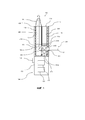
На фиг. 1 схематично показано гибридное устройства согласно изобретению;FIG. 1 schematically shows a hybrid device according to the invention;
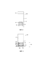
на фиг. 2 схематично показан картридж для материала для использования в гибридном устройстве по фиг. 1, вид сбоку;in fig. 2 schematically shows a material cartridge for use in the hybrid device of FIG. 1, side view;
на фиг. 3 схематично показан картридж для жидкости для использования в гибридном устройстве по фиг. 1, вид сбоку;in fig. 3 schematically shows a fluid cartridge for use in the hybrid device of FIG. 1, side view;
на фиг. 4a - картридж для материала и мундштук, вид в перспективе с первой стороны;in fig. 4a is a first side perspective view of the material cartridge and mouthpiece;
на фиг. 4b - картридж для материала и мундштук по фиг. 4a, вид в перспективе со второй стороны;in fig. 4b shows the material cartridge and mouthpiece of FIG. 4a is a perspective view from the second side;
на фиг. 5 схематично показаны картридж для жидкости, картридж для материала и мундштук;in fig. 5 schematically shows a liquid cartridge, a material cartridge and a mouthpiece;
на фиг. 6 схематично показаны картридж для материала и картридж для жидкости, имеющий два резервуара, вид сверху.in fig. 6 is a schematic top view of a material cartridge and a liquid cartridge having two reservoirs.
Осуществление изобретенияImplementation of the invention
На фиг. 1 схематично показано устройство 100 подачи аэрозоля. Устройство 100 подачи аэрозоля является портативным ингаляционным устройством (т.е. пользователь использует его для вдыхания аэрозоля, вырабатываемого системой 100). В этом примере устройство 100 является электронным устройством.FIG. 1 schematically shows an
В общих чертах, устройство 100 испаряет аэрозольобразующий материал 20, находящийся в компоненте 200 выработки аэрозоля. В этом примере аэрозольобразующий материал 20 является жидкостью, например, жидкостью для электронных сигарет, однако в других примерах аэрозольобразующий материал может быть любого другого типа, например, гелем. Устройство 100 в этом примере является гибридным устройством, поскольку аэрозоль и/или пар, вырабатываемый компонентом 200, перед вдыханием его пользователем проходит через камеру 430, содержащую материал 30 (фиг. 2).In general terms, the
Материал 30 может придавать какое-либо свойство или модифицировать какое-либо свойство, например аромат, пара и/или аэрозоля, прежде чем пар и/или аэрозоль пройдут через устройство 100 для вдыхания пользователем. Материал 30 может состоять из табака или содержать табак. Когда аэрозоль проходит через материал 30, например табак, аэрозоль захватывает органические и другие соединения или компоненты из этого материала 30, которые придают материалу 30, например табаку, органолептические свойства, тем самым, придавая аромат материала 30 аэрозолю, когда он проходит через камеру 430.The
Соответствующие примеры материала 30 могут включать в себя собственно табак, различные разновидности табака, производные табака, экспандированный табак, восстановленный табак, молотый табак, табачный экстракт, гомогенизированный табак или заменители табака. В случае табака материал 30 может быть в форме табачного стержня, табачной таблетки или табачной плитки, рассыпного табака, брикетов и т.д. и может быть, к примеру, в относительно сухой или относительно влажной форме. Материал 30 может быть в стержне из прессованного табака, который разрезан в размер и помещен в камеру 430. Материал 30 может содержать и другие нетабачные продукты, которые, в зависимости от продукта, могут содержать или не содержать никотин.Suitable examples of
Материал 30 может, например, модифицировать другое свойство аэрозоля помимо (или в дополнение) аромата.The material 30 can, for example, modify another property of the aerosol in addition to (or in addition to) flavor.
В некоторых примерах материал 30 может быть веществом или содержать вещество, которое модифицирует одно или несколько других органолептических свойств аэрозоля (например, модифицирует его вкус, или запах, или внешний вид).In some examples,
В некоторых примерах материал 30 может быть веществом или содержать вещество, которое модифицирует pH аэрозоля, повышая или увеличивая его (например, модифицирует кислотность или щелочность аэрозоля).In some examples,
В некоторых примерах материал 30 может быть веществом или содержать вещество, которое модифицирует (например, уменьшает) количество альдегидов а аэрозоле.In some examples,
В некоторых примерах материал 30 может быть веществом или содержать вещество, которое модифицирует различные комбинации двух или большего числа свойств или, фактически, других свойств потока аэрозоля.In some examples,
Однако следует принять во внимание, что для придания аэрозолю различных ароматов помимо табака могут использоваться другие материалы.However, it should be appreciated that materials other than tobacco can be used to impart different flavors to the aerosol.
Если материал 30 является табаком или содержит табак, аэрозоль может захватывать достаточное количество никотина из материала 30. Как вариант или дополнительно, если материал 30 не содержит табака, он может обогащаться никотином, например, за счет покрытия этого материала никотином. Фактически, даже в случае, если материал 30 является табаком или содержит табак, он может быть покрыт или иным образом обогащен никотином. В качестве другого примера, независимо от того, является ли материал 30 табаком или содержит табак, и/или содержит никотин, никотин может содержаться в аэрозольобразующем материале, в данном случае в жидкости 20. Соответственно, если система 100 предназначена для подачи никотина пользователю, никотин может содержаться в аэрозольобразующем материале 20, может быть получен из материала 30 в случае, если этот материал является табаком или содержит табак, может содержаться в виде покрытия или т.п. на материале 30, если он является нетабачным материалом, может содержаться в виде покрытия или т.п. на материале 30, если он является табачным материалом, или может быть получен с помощью любой комбинации указанных способов. Сходным образом, в материал 30 (независимо от того, является вещество табаком или содержит табак) или в аэрозольобразующий материал могут быть добавлены ароматизаторы.If the
По меньшей мере, в некоторых примерах производится пар, который по меньшей мере частично конденсируется и образует аэрозоль перед выходом из устройства предоставления аэрозоля через камеру для материала для вдыхания пользователем (не показано).In at least some examples, steam is produced which at least partially condenses and forms an aerosol before exiting the aerosol delivery device through a material chamber for inhalation by a user (not shown).
Следует отметить, что, в общем, пар является веществом в газовой фазе при температуре ниже его критической температуры. Это означает, что, например, пар может конденсироваться в жидкость за счет увеличения его давления без уменьшения температуры. С другой стороны, в общем, аэрозоль является коллоидом из мелких твердых частиц или капель жидкости в воздухе или другом газе. «Коллоид» является веществом, в котором, рассеянные микроскопические нерастворимые частицы взвешены в другом веществе.It should be noted that, in general, vapor is a substance in the gas phase below its critical temperature. This means that, for example, steam can condense into a liquid by increasing its pressure without decreasing the temperature. On the other hand, in general, an aerosol is a colloid of fine solid particles or liquid droplets in air or other gas. A "colloid" is a substance in which scattered microscopic insoluble particles are suspended in another substance.
Для удобства в дальнейшем описании термин «аэрозоль» означает аэрозоль, пар или комбинацию аэрозоля и пара.For convenience, in the following description, the term "aerosol" means an aerosol, vapor, or a combination of aerosol and vapor.
Как показано на фиг. 1, гибридное устройство 100 содержит первую секцию 200, в этом примере картридж 200 для выработки аэрозоля (в некоторых случаях ниже называемый картриджем для жидкости), основную часть 300 устройства и вторую секцию для размещения материала, в этом примере картридж 400 для материала. В этом примере картридж 400 для материала содержит мундштук 50, который может быть выполнен за одно целое с картриджем для материала или может крепиться с возможностью отсоединения на его верхнем конце 450 (или ближнем или мундштучном конце, поскольку этот конец во время использования расположен наиболее близко ко рту пользователя).As shown in FIG. 1, the
Основная часть 300 устройства содержит нижний кожух 310, в котором расположен источник 320 питания, как правило батарея, для подачи питания на различные компоненты устройства 100. Батарея 320 может быть перезаряжаемой или одноразовой. В нижнем кожухе 310 также расположен контроллер 330, который может содержать микрочип, входящий в схему системы управления функционированием различных компонентов устройства 100. Снаружи нижнего кожуха 310 для управления контроллером 330 могут быть расположены средства 340 ввода пользователя, например, одна или несколько кнопок управления.The
В этом примере основная часть 300 устройства также содержит верхний кожух 350, который проходит до ближнего конца 150 устройства 100 и ограничивает полость, в которую вставлены картридж 200 для жидкости и картридж 400 для материала. В других примерах основная часть 300 устройства может не содержать верхнего кожуха, и картриджи для жидкости и материала могут быть прикреплены только к нижнему кожуху устройства, или источник питания и электронные схемы управления могут быть расположены в картридже для жидкости или картридже для материала, и в таких случаях устройство не содержит основной части.In this example, the
Как можно видеть на фиг. 1, картридж 200 для жидкости и картридж 400 для материала расположены бок о бок. В контексте настоящего описания расположение «бок о бок» означает, что боковая сторона секции для жидкости, по существу, совмещена с боковой стороной секции для материала, и указанные секции по существу параллельны продольной оси устройства. Такая компоновка отличается от компоновки стандартных гибридных устройств, в которых картриджи с материалом и жидкостью расположены в линию торец к торцу.As can be seen in FIG. 1, the
Расположение бок о бок согласно изобретению отличается от линейных гибридных устройств и позволяет получить более компактное устройство. Кроме того, устройство согласно изобретению позволяет по отдельности отсоединять от устройства или картридж для жидкости, или картридж для материала, что невозможно в линейных гибридных устройствах.The side-by-side arrangement of the invention differs from linear hybrid devices and allows for a more compact device. In addition, the device according to the invention makes it possible to separately detach from the device either the liquid cartridge or the material cartridge, which is not possible with linear hybrid devices.
В этом примере верхняя или ближняя часть картриджа 200 для жидкости содержит резервуар 220, в котором находится жидкость 20, а нижняя или дальняя часть картриджа 200 содержит средство 260 приведения в аэрозольное состояние жидкости 20 из резервуара 220. В этом примере средство 260 приведения в аэрозольное состояние содержит нагреватель.In this example, the upper or proximal portion of the
Предпочтительно, средство 260 приведения в аэрозольное состояние может содержать по меньшей мере один фитиль, подающий жидкость к по меньшей мере одному нагревательному элементу для приведения жидкости 20 в аэрозольное состояние. Нагреватель может содержать несколько нагревательных элементов, каждый из которых может быть прямолинейным или в виде катушки. Каждый фитиль может подавать жидкость к одном нагревательному элементу или ко всем нагревательным элементам или любому их количеству.Preferably, the aerosolizing means 260 may comprise at least one wick supplying fluid to at least one heating element for aerosolizing the fluid 20. The heater can contain several heating elements, each of which can be straight or in the form of a coil. Each wick can supply fluid to one heating element or to all or any number of heating elements.
В нагревательном элементе согласно этому примеру жидкость 20 поступает из резервуара 220 с помощью первого фитиля 240a (фиг. 3) и приводится в аэрозольное состояние первой нагревательной катушкой 250a, и с помощью второго фитиля 240b (фиг. 3) и приводится в аэрозольное состояние второй нагревательной катушкой 250b. Подробное описание функционирования этой системы с двумя катушками приведено ниже со ссылкам на фиг. 3 и 5.In the heating element according to this example, liquid 20 is supplied from the
В других примерах средство 260 приведения в аэрозольное состояние может не содержать нагревательные средства или может не содержать фитиля и может содержать, например, ультразвуковой атомайзер.In other examples, the aerosolizing means 260 may not contain heating means or may not contain a wick, and may include, for example, an ultrasonic atomizer.
Предпочтительно жидкость 20 способна испаряться при приемлемых температурах, предпочтительно 100-300°C, или более предпочтительно примерно 150-250°C для сдерживания расхода энергии системы 100. Подходящими материалами являются материалы, традиционно используемые в устройствах электронных сигарет, в том числе, например, пропиленгликоль и глицерол (также известный как глицерин). Преимущественно, первая и вторая нагревательные катушки 250a, 250b расположены таким образом, что они также нагревают материал 30 в камере 430, увеличивая тем самым влияние материала 30 на аэрозоль, текущий через этот материал.Preferably, the liquid 20 is capable of vaporizing at acceptable temperatures, preferably 100-300 ° C, or more preferably about 150-250 ° C, to contain the energy consumption of the
В этом примере нижний или дальний конец 270 картриджа для жидкости имеет точки электрического контакта (не показано) для формирования электрического соединения с нижним кожухом 310 основной части устройства. По существу первая и вторая нагревательные катушки 250a и 250b запитываются от батареи 320 и управляются контроллером 330.In this example, the lower or
Во время использования пользователь делает затяжку через мундштук 50, и воздух втягивается через одно или несколько отверстий 411 (поток воздуха показан на фиг. 1 стрелкой 10) в направлении, по существу перпендикулярном продольной оси устройства 100. Нагревательные катушки 250a, 250b запитываются посредством приведения пользователем в действие кнопки 340 управления (или, как вариант, с помощью известного датчика затяжки), и жидкость 20 втягивается из резервуара 220 с помощью первого фитиля 240a и второго фитиля 240b и нагревается катушками для испарения жидкости 20 и генерирования аэрозоля.During use, the user puffs through the
Средство 260 приведения в аэрозольное состояние, содержащий нагревательные катушки 250a, 250b, содержит открытую секцию 290 (показанную на фиг. 1 точечными линиями). Эта открытая секция 290 является окном (показано на фиг. 3), которое позволяет воздуху, втягиваемому через отверстие 411, достигать катушек 250a, 250b, где воздух смешивается с генерируемым аэрозолем. В дальнейшем поток 10 покидает картридж 200 для жидкости в виде потока воздуха с захваченным аэрозолем (далее просто называемым потоком аэрозоля) и поступает в картридж 400 для материала.The aerosolizing means 260 comprising
Картридж 400 для материала содержит камеру 430, в которую помещен материал 30. Картридж 400 для материала содержит первый кожух, имеющий пористую секцию 490 (показанную пунктирной линией на фиг. 1) во внутренней стенке первого кожуха, т.е. стенке первого кожуха, которая обращена к картриджу 200 для жидкости.The
Как описано выше, во время использования картридж 200 для жидкости и картридж 400 для материала расположены бок о бок. Открытая секция 290 картриджа 200 для жидкости выровнена с пористой секцией 490 картриджа 400 для материала. Вокруг открытой секции 290 проходит первое уплотнение 280 (фиг. 3), а вокруг пористой секции 490 проходит второе уплотнение 480 (фиг. 2). Первое уплотнение 280 и второе уплотнение 480 упираются друг в друга (как показано на фиг. 5), образуя герметизированный проход для аэрозоля, проходящего из открытой секции 290 камеры для жидкости через пористую секцию 490 картриджа для материала в камеру 430 для материала.As described above, during use, the
Когда пользователь делает затяжку, используя это устройство, поток 10 аэрозоля втягивается из средства 260 приведения в аэрозольное состояние в камеру 430 для материала через пористую секцию 490. Поток 10 аэрозоля втягивается через камеру 430 для материала в направлении, параллельном продольной оси устройства 100, к мундштуку 50, проходя через материал 30, в этом примере табачный материал. Когда поток 10 аэрозоля проходит через материал 30, один или несколько компонентов материала 30 захватываются в поток аэрозоля, что может изменять или добавлять свойства аэрозолю, например, вкус.When the user puffs using this device, a stream of
Можно видеть (например, на фиг. 1 и 5), что, поскольку картридж 200 для жидкости и картридж 400 для материала во время использования расположены бок о бок, камера 430 для материала расположена рядом с нижней частью картриджа 200 для жидкости, который содержит первую нагревательную катушку 250a и вторую нагревательную катушку 250b. По существу, материал 30, в данном случае табачный материал, расположен в непосредственной близости от первой нагревательной катушки 250a и второй нагревательной катушки 250b, и табак 30 может нагреваться непосредственно нагревательными катушками 250a, 250b.It can be seen (for example, in FIGS. 1 and 5) that since the
Дополнительное преимущество расположения бок о бок состоит в том, что камера 430 для материала имеет большую площадь поверхности, обращенную к нагревательным катушкам 250a, 250b. По сравнению со стандартным линейным гибридным устройством может быть обеспечен более эффективный равномерный нагрев табака. Аэрозоль, проходящий через материал, обогащается в результате более эффективного нагрева.An additional advantage of the side-by-side arrangement is that the
Расположение бок о бок также позволяет использовать относительно большую пористую секцию 490, которая в некоторых примерах имеет по существу четырехугольную форму, как показано на фиг. 2. Пористая секция 490 имеет большую площадь поверхности для передачи потока 10 аэрозоля из картриджа 200 для жидкости в камеру 430 для материала. Другое преимущество расположения бок о бок состоит в том, что оно обеспечивает боле короткую траекторию движения потока 10 аэрозоля, в результате чего поток аэрозоля теряет меньше тепла, и материалу и пользователю может передаваться более теплый пар. Эти признаки способствуют более эффективному изменению свойств аэрозоля, поскольку по сравнению с линейным устройством на большую площадь поверхности материала 30 подается более теплый аэрозоль.The side-by-side arrangement also allows the use of a relatively large
Во время использования, в частности, если материал является табаком, предпочтительно, чтобы табак или, по меньшей мере, его поверхность, нагревалась до температуры приблизительно 100-210°C, и наиболее предпочтительно до приблизительно 200°C, так чтобы из табака высвобождалось надлежащее или соответствующее количество соединений. Количество имеющегося табака может составлять, например, 50-300 мг или около этого. Наиболее пригодное количество табака может составлять, например, 50-150 мг. Как установлено в настоящее время количество 130 мг является наиболее пригодным в некоторых применениях. В типовом примере количество табака, нагреваемое на одно действие системы (т.е. на одну затяжку), может составлять приблизительно 8-50 мг.During use, in particular if the material is tobacco, it is preferred that the tobacco, or at least its surface, is heated to a temperature of about 100-210 ° C, and most preferably to about 200 ° C, so that the tobacco is adequately released. or the corresponding number of connections. The amount of tobacco present can be, for example, 50-300 mg or so. The most suitable amount of tobacco may be, for example, 50-150 mg. The amount of 130 mg is currently found to be most useful in some applications. In a typical example, the amount of tobacco heated per action of the system (i.e., per puff) may be about 8-50 mg.
На фиг. 2 показан картридж 400 для материала для устройства по фиг. 1. Материал 30 содержится в нижней части 430 картриджа 400 для материала. В стенке, обращенной к картриджу 200 для жидкости, расположена пористая мембрана 490. В этом примере пористая мембрана 490 содержит мягкую мелкую сетку, но в других примерах пористая мембрана может быть любым пористым барьером, пригодным для содержания в камере 430 материала 30, например твердого табачного материала, и обеспечения поступления аэрозоля в эту камеру. Пористая мембрана 490 позволяет потоку 10 аэрозоля из картриджа 200 для жидкости проходить в табачный материал 30, как описано выше со ссылкой на фиг. 1. Пористая мембрана 490 может содержать пластический материал, такой как полипропилен, или металл, такой как нержавеющая сталь или алюминий, и может содержать, например, алюминиевую фольгу. Пористая мембрана 490 может иметь толщину приблизительно от 0,1 до 1,2 мм. Например, пористая мембрана может иметь толщину приблизительно 1,2 мм, когда она содержит пластический материал, и толщину приблизительно 0,1 мм, когда она содержит металл. Преимущественно пористая мембрана 490 является сеткой с максимальным размером отверстий, меньшим диаметра материала 30, содержащегося в камере. Например, если материалом 30 является табак, максимальный размер отверстий сетки может составлять приблизительно от 0,2 до 0,7 мм. Максимальный размер отверстий сетки выбирается в зависимости от типа используемого табака.FIG. 2 shows a
Пористая мембрана удерживает материал 30 на месте, обеспечивая сенсорное взаимодействие пользователя с материалом 30 внутри картриджа 400 для материала перед креплением картриджа к устройству 100. Например, если материал 30 является табаком, пользователь может почувствовать запах табака через пористую мембрану 490 при манипуляциях с картриджем 400 для табака. В этом примере по меньшей мере часть камеры 430 для материала является прозрачной, позволяя пользователю видеть табак и дополнительно усиливая чувственное восприятие пользователя. Второе уплотнение 480 проходит вокруг пористой секции 490 и удерживает пористую мембрану на месте, препятствуя выходу материала 30 из картриджа 400 для материала. Пористая мембрана 490 является теплостойкой и выдерживает воздействие тепла, генерируемого нагревательными катушками 250a, 250b.The porous membrane holds the material 30 in place by allowing the user to touch the
На фиг. 4a показан картридж 400 для материала с мундштуком 50, если смотреть с первой наружной стороны. При этом нижняя часть картриджа показана в частичном разрезе. На фиг. 4b показан второй вид того же самого картриджа для материала со второй внутренней стороны. При этом верхняя часть мундштука 50 картриджа показана в частичном разрезе.FIG. 4a shows a
На фиг. 4a показана наружная сторона картриджа 400, т.е. сторона, которая не примыкает во время использования к картриджу 200 для жидкости. Поперек верха камеры 430 для материала картриджа 400 для табака по существу горизонтально проходит первый барьер 40, удерживая табак 30 в камере 430. Первый барьер 40 является пористым и обеспечивает прохождение потока 10 аэрозоля (фиг. 1), но препятствует выходу материала 30 из камеры 430 в верхнюю часть 420 картриджа для материала. В этом примере первый барьер 40 является сеткой. если первый барьер 40 является сеткой, эта сетка может содержать любой из материалов, описанных выше в отношении пористой мембраны 490. Преимущественно, материал первого барьера является термостойким, способным выдерживать температуры приблизительно до 180°C.FIG. 4a shows the outside of the
В этом примере мундштук 50 прикреплен к картриджу 400 для табака. В других примерах мундштук 50 может быть разъемно соединен с картриджем для табака. В других примерах мундштук 50 может быть образован за одно целое с картриджем 400 для материала. Сверху верхней части 420 картриджа 400 для табака по существу горизонтально проходит второй барьер 60. Второй барьер 60 обеспечивает дополнительную защиту от случайного вдыхания пользователем материала 30 из камеры 430. Кроме того, вторая сетка расположена на расстоянии по вертикали от мундштучного отверстия 510 мундштука 50. Это расстояние позволяет получить камеру 580 мундштука, которая способствует уменьшению утечки материала 30 в рот пользователя. Когда аэрозоль проходит через материал 30, такой как табак, часть аэрозоля может конденсироваться, образуя конденсат. В устройствах, в которых материал расположен слишком близко ко рту пользователя, конденсат может выходить из устройства в рот пользователя. Вертикальное расстояние между материалом 30 и мундштуком 50, обеспечиваемое вторым барьером 60, препятствует попаданию конденсата в рот пользователя. Картридж 400 для табака в этом примере также можно видеть на фиг. 5, где верхняя часть 420 камеры для табака и камера мундштука показаны в схематическом разрезе.In this example, the
Из фиг. 4b и 5 можно видеть, что ширина камеры 430 для материала меньше ширины верха верхней части 420 картриджа для материала. В этом примере мундштук 50 прикреплен к верху картриджа 400 для материала, который увеличивается по ширине в направлении его верхнего конца. Картридж 400 для материала имеет внутреннюю сторону, которая по существу параллельна продольной оси устройства 100 у камеры 430, но которая изгибается таким образом, что ширина картриджа 400 для материала увеличивается в направлении к верху верхней части 420 картриджа для материала. Таким образом, внутренняя сторона картриджа 400 для материала имеет форму, обеспечивающую размещение картриджа 200 для жидкости, как показано на фиг. 5, когда оба картриджа размещены бок о бок.From FIG. 4b and 5, it can be seen that the width of the
На фиг. 3 схематично показан картридж 200 для жидкости устройства по фиг. 1. Картридж для жидкости содержит резервуар 220, в котором находится жидкость 20. Дальний участок картриджа 200 для жидкости содержит средство 260 приведения в аэрозольное состояние. Средство 260 приведения в аэрозольное состояние содержит первый фитиль 240a для подачи жидкости 20 из резервуара 220 к первой нагревательной катушке 250a и второй фитиль 240b для подачи жидкости 20 из резервуара 220 ко второй нагревательной катушке 250b. Резервуар 220 в этом примере проходит к обеим сторонам средства 260 приведения в аэрозольное состояние картриджа 200, и первый и второй фитили 240a, 240b проходят от обеих сторон нижней части резервуара 220.FIG. 3 schematically shows a
Первый и второй фитили 240a, 240b находятся в жидкостном контакте с жидкостью, содержащейся в резервуаре 220. Фитили 240a, 240b, в общем, являются поглощающими фитилями и всасывают жидкость 20 из резервуара 220 за счет капиллярного эффекта. Фитили 240a, 240b предпочтительно изготавливаются из нетканого материала и могут быть изготовлены, например, из хлопка или шерсти или т.п., или из синтетического материала, включая, например, полиэфир, нейлон, вискозу, полипропилен или т.п., или из керамического материала.The first and
Как упомянуто выше со ссылкой на фиг. 1, средство 260 приведения в аэрозольное состояние содержит открытую секцию 290, которая позволяет потоку воздуха перемещаться из отверстий 411 для захватывания аэрозоля, производимого на первой катушке 240a и второй катушке 240b. Вокруг открытой секции 290 проходит второе уплотнение 280. Средство 260 приведения в аэрозольное состояние содержит верхнюю планку 230a, которая является сплошной, проходящей по ширине открытой секции 290 у ближнего конца средства 260 приведения в аэрозольное состояние. Также имеется нижняя планка 230b, которая тоже является сплошной, проходящей по ширине картриджа 200 для жидкости у дальнего конца 270 картриджа. Нижняя планка 230b содержит электрические контакты для соединения нагревательных катушек 250a, 250b с основной частью 300 устройства.As mentioned above with reference to FIG. 1, the aerosolization means 260 includes an
Нагрев материала 30 является важным фактором в создании у пользователя удовлетворительного чувственного восприятия. Например, если материал 30 содержит табак, нагрев табака усиливает у пользователя ощущение вкуса табака и может способствовать захватыванию в поток аэрозоля большего числа составляющих, например, никотина.Heating the
Использование нагревателя, который содержит первый нагревательный и второй нагревательные элементы, расположенные с возможностью нагрева материала 30, обеспечивает эффективную передачу тепла материалу 30, и позволяет нагревать относительно большую площадь поверхности вещества 30. Кроме того, количество расходуемой энергии на нагревательный элемент, может быть меньше количества энергии, которое потребовалась бы для нагревательного устройства только с одним элементом.The use of a heater that includes a first heating element and a second heating element positioned to heat the
Первый нагревательный элемент 250a и второй нагревательный элемент 250b расположены рядом с камерой 430, когда картридж 200 для жидкости и картридж 400 для материала расположены бок о бок. Соответственно, первый нагревательный элемент 250a и второй нагревательный элемент 250b расположены достаточно близко к камере 430, чтобы они могли нагревать вещество 30 и повышать его температуру, когда первый и второй нагревательные элементы 250a и 250b приведены в действие.The
Первый и второй нагревательные элементы 250a и 250b в этом примере расположены в общей плоскости, которая, по существу, параллельна пористой секции 490 камеры 430 для материала. Это расположение способствует равномерному нагреву вещества 30 в камере 430.The first and
Первый и второй нагревательные элементы 250a и 250b могут быть удлиненными и расположенными по существу параллельно, обеспечивая равномерный нагрев вещества 30 в камере 430.The first and
Каждый из нагревательных элементов 250a и 250b может быть электрическим резистивным нагревателем, например, нихромовым резистивным нагревателем, керамическим нагревателем и т.д. В показанном примере первый и второй нагревательные элементы 250a и 250b выполнены из проволоки в форме катушки. Каждый из нагревательных элементов может быть прямолинейной катушкой, криволинейной катушкой, вертикальной катушкой или спиральной катушкой.Each of the
В других примерах каждый из нагревательных элементов может иметь форму пластины (которая может быть многослойной пластиной из двух или более различных материалов, один или несколько из которых могут быть электропроводными, а другие один или несколько - неэлектропроводными), сетки (которая может быть, например, тканой или нетканой и которая может быть сходным образом многослойной), пленочного нагревателя и т.д.In other examples, each of the heating elements can be in the form of a plate (which can be a multilayer plate of two or more different materials, one or more of which can be electrically conductive and the other one or more non-conductive), a grid (which can be, for example, woven or non-woven and which may be similarly multi-layer), film heater, etc.
В качестве первого и второго нагревательных элементов 250a и 250b также можно использовать другие нагреватели, например, неэлектрические нагреватели или другие электрические нагреватели, причем каждый из нагревательных элементов 250a и 250b может быть индукционным.Other heaters may also be used as the first and
В примере, показанном на фигурах, первый и второй нагревательные элементы 250a и 250b выполнены по существу линейными (т.е. прямолинейными) резистивными нагревательными элементами, каждый из которых окружает соответствующий фитиль 240a, 240b, находящийся в (тепловом) контакте с соответствующим нагревательным элементом 250a или 250b. Фитили 240a, 240b также находятся в жидкостном контакте с жидкостью 20, находящейся в резервуаре 220. Фитили 240a, 240b, в общем, являются поглощающими фитилями и всасывают жидкость 20 из резервуара 220 для жидкости за счет капиллярного эффекта.In the example shown in the figures, the first and
Предпочтительно фитили 240a, 240b изготавливаются из нетканого материала и могут быть изготовлены, например, из хлопка или шерсти или т.п., или из синтетического материала, включая, например, полиэфир, нейлон, вискозу, полипропилен или т.п., или из керамического материала.Preferably, the
В некоторых примерах контроллер 330 выполнен с возможностью независимого приведения в действие первого и второго нагревательных элементов 250a и 250b.In some examples, the
В таких примерах контроллер 330 выполнен с возможностью приведения в действие одного из нагревательных элементов 250a или 250b, в то время как другой из этих нагревательных элементов не приводится в действие.In such examples, the
Во время использования, в частности, если материал 30 является табаком, предпочтительно, чтобы табак или, по меньшей мере, его поверхность нагревалась до температуры приблизительно 190-210°C, наиболее предпочтительно - приблизительно до 200°C, чтобы из табака высвобождалось надлежащее или соответствующее количество соединений.During use, in particular if the
Количество имеющегося табака может составлять 50-300 мг или около того. Наиболее пригодное количество табака может составлять 50-150 мг, с количеством 130 мг, которое, как установлено в настоящее время, является наиболее пригодным в некоторых применениях. В типовом примере количество табака, нагреваемое на одно действие системы (т.е. на одну затяжку), может составлять приблизительно 8-50 мг.The amount of tobacco present can be 50-300 mg or so. The most suitable amount of tobacco may be 50-150 mg, with 130 mg currently found to be most useful in some applications. In a typical example, the amount of tobacco heated per action of the system (i.e., per puff) may be about 8-50 mg.
Расположение бок о бок картриджа 200 для подачи аэрозоля и картриджа 400 для материала позволяет размещать в картридже 200 два резервуара для аэрозольобразующих веществ, например, содержащих жидкости с различными запахами. В примере, показанном на фиг. 6, картридж 200 содержит резервуар 220' для первой жидкости и резервуар 220'' для второй жидкости, при этом картридж 200 разделен по вертикали на две секции, таким что резервуар 220' для первой жидкости занимает первую секцию картриджа, а резервуар 220'' для второй жидкости занимает вторую секцию картриджа.The side-by-side arrangement of the
В некоторых вариантах выполнения устройство 100 может также содержать гигиеническую крышку (не показана) для закрывания по меньшей мере части устройства 100 и поддержания этой части устройства 100 в чистоте, когда оно помещено, например, в сумку или в карман пользователя. Гигиеническая крышка может обеспечивать эстетические преимущества и может иметь, например, металлическую отделку, рисунки на поверхности или разные цвета и т.д. Устройство 100 может быть вставлено в гигиеническую крышку или с ближнего конца или с дальнего конца. В некоторых примерах гигиеническая крышка может иметь контакты на внутренней стороне, которые могут контактировать со средствами 340 ввода пользователя и позволяют пользователю приводить устройство 100 в действие, когда крышка всё еще находится на устройстве.In some embodiments, the
В настоящем описании термины «вкусовое вещество» и «ароматизатор» относятся к материалам, которые, если это разрешают государственные нормативные правовые акты, можно использовать для создания желаемого вкуса или аромата в изделии для взрослых потребителей. Они могут включать в себя экстракты (например, лакрицу, гортензию, лист белой японской магнолии, ромашку, пажитник, гвоздику, ментол, мяту японскую, анисовое семя, корицу, траву, гаултерию, вишню, ягоду, персик, яблоко, драмбьюи, бурбон, шотландский виски, виски, мяту курчавую, перечную мяту, лаванду, кардамон, сельдерей, каскарилью, мускатный орех, сандаловое дерево, бергамот, герань, экстракт меда, розовое масло, ваниль, лимонное масло, апельсиновое масло, кассию, тмин, коньяк, жасмин, канангу душистую, шалфей, фенхель, перец гвоздичный, имбирь, анис, кориандр, кофе или мятное масло из мяты любого вида), усилители вкуса, блокираторы участка рецепторов горечи, активаторы или стимуляторы участка рецепторов обоняния, сахар и/или заменители сахара (например, сукралозу, ацесульфам калия, аспартам, сахарин, цикламат, лактозу, сахарозу, глюкозу, фруктозу, сорбит или маннитол) и другие добавки, такие как древесный уголь, хлорофилл, минералы, растительное сырье или вещества для освежения полости рта. Они могут быть имитационными, искусственными или натуральными ингредиентами или их смесями. Они могут иметь любую пригодную форму, например, могут быть маслом, жидкостью или порошком.As used herein, the terms "flavoring" and "flavoring" refer to materials that, if permitted by government regulations, can be used to create the desired taste or aroma in an adult product. These may include extracts (e.g., licorice, hydrangea, white Japanese magnolia leaf, chamomile, fenugreek, cloves, menthol, mint, aniseed, cinnamon, herb, goulteria, cherry, berry, peach, apple, drambuy, bourbon scotch whiskey, whiskey, spearmint, peppermint, lavender, cardamom, celery, cascarilla, nutmeg, sandalwood, bergamot, geranium, honey extract, rose oil, vanilla, lemon oil, orange oil, cassia, cumin, cognac, jasmine , cananga, sage, fennel, cloves, ginger, anise, coriander, coffee or peppermint oil of any kind), flavor enhancers, bitter receptor site blockers, olfactory receptor site activators or stimulants, sugar and / or sugar substitutes (for example , sucralose, acesulfame potassium, aspartame, saccharin, cyclamate, lactose, sucrose, glucose, fructose, sorbitol or mannitol) and other additives such as charcoal, chlorophyll, minerals, plant materials or polo fresheners wash your mouth. They can be imitation, artificial or natural ingredients, or mixtures thereof. They can be in any suitable form, for example, oil, liquid or powder.
Изобретение направлено на устранение существующих проблем и усовершенствование известных устройств и в полной мере раскрывается в описании вариантов его осуществления, проиллюстрированных в качестве примера и практического использования изобретения, в котором предлагается усовершенствованная система, выполненную с возможностью генерирования вдыхаемой среды. Преимущества и особенности изобретения представляют собой исключительно репрезентативную выборку из вариантов осуществления изобретения и не являются исчерпывающими и/или исключительными. Варианты осуществления изобретения описаны лишь для облегчения его понимания. Следует понимать, что преимущества, варианты осуществления, примеры, функции, особенности конструкции и/или другие аспекты изобретения не должны рассматриваться как ограничивающие изобретение, которое определено его формулой, и что возможны другие варианты осуществления изобретения и допускаются изменения, не выходящие за рамки объема и/или сущности изобретения. Различные варианты осуществления изобретения, разумеется, могут содержать, состоять или в основном состоять из различных комбинаций раскрытых элементов, компонентов, особенностей, частей, этапов, средств и т.д.The invention is aimed at eliminating the existing problems and improving the known devices and is fully disclosed in the description of the variants of its implementation, illustrated as an example and practical use of the invention, which proposes an improved system capable of generating a respirable medium. The advantages and features of the invention are only a representative selection of embodiments of the invention and are not exhaustive and / or exclusive. Embodiments of the invention have been described for ease of understanding only. It should be understood that the advantages, embodiments, examples, functions, design features, and / or other aspects of the invention should not be construed as limiting the invention as defined by the claims, and that other embodiments of the invention are possible and subject to changes without departing from the scope and / or the essence of the invention. Various embodiments of the invention may, of course, comprise, consist of, or mainly consist of various combinations of the disclosed elements, components, features, parts, steps, means, etc.
Claims (49)
Applications Claiming Priority (3)
| Application Number | Priority Date | Filing Date | Title |
|---|---|---|---|
| GB1717498.8 | 2017-10-24 | ||
| GBGB1717498.8A GB201717498D0 (en) | 2017-10-24 | 2017-10-24 | Aerosol provision device |
| PCT/EP2018/079139 WO2019081571A1 (en) | 2017-10-24 | 2018-10-24 | Aerosol provision device |
Related Child Applications (1)
| Application Number | Title | Priority Date | Filing Date |
|---|---|---|---|
| RU2021129125A Division RU2794459C2 (en) | 2017-10-24 | 2021-10-06 | Aerosol delivery device |
Publications (1)
| Publication Number | Publication Date |
|---|---|
| RU2757841C1 true RU2757841C1 (en) | 2021-10-21 |
Family
ID=60481839
Family Applications (1)
| Application Number | Title | Priority Date | Filing Date |
|---|---|---|---|
| RU2020114662A RU2757841C1 (en) | 2017-10-24 | 2018-10-24 | Aerosol delivery device |
Country Status (21)
| Country | Link |
|---|---|
| US (2) | US11439778B2 (en) |
| EP (3) | EP3649876B1 (en) |
| JP (4) | JP6825187B1 (en) |
| KR (2) | KR20200123877A (en) |
| CN (1) | CN111587076A (en) |
| AU (2) | AU2018355717B2 (en) |
| BR (1) | BR112020008104A2 (en) |
| CA (2) | CA3188149A1 (en) |
| CL (1) | CL2020001064A1 (en) |
| ES (1) | ES2875825T3 (en) |
| GB (1) | GB201717498D0 (en) |
| HU (1) | HUE054598T2 (en) |
| IL (1) | IL273950B2 (en) |
| MX (1) | MX2020004171A (en) |
| MY (1) | MY190390A (en) |
| NZ (1) | NZ763911A (en) |
| PH (1) | PH12020550430A1 (en) |
| PL (1) | PL3614870T3 (en) |
| RU (1) | RU2757841C1 (en) |
| UA (1) | UA127483C2 (en) |
| WO (1) | WO2019081571A1 (en) |
Families Citing this family (32)
| Publication number | Priority date | Publication date | Assignee | Title |
|---|---|---|---|---|
| GB201700136D0 (en) | 2017-01-05 | 2017-02-22 | British American Tobacco Investments Ltd | Aerosol generating device and article |
| GB201700620D0 (en) | 2017-01-13 | 2017-03-01 | British American Tobacco Investments Ltd | Aerosol generating device and article |
| GB201717498D0 (en) | 2017-10-24 | 2017-12-06 | British American Tobacco Investments Ltd | Aerosol provision device |
| GB201717496D0 (en) | 2017-10-24 | 2017-12-06 | British American Tobacco Investments Ltd | A cartridge for an aerosol provision device |
| GB201720338D0 (en) | 2017-12-06 | 2018-01-17 | British American Tobacco Investments Ltd | Component for an aerosol-generating apparatus |
| GB201802591D0 (en) * | 2018-02-16 | 2018-04-04 | Nicoventures Trading Ltd | Aerosol provision article |
| GB201802590D0 (en) * | 2018-02-16 | 2018-04-04 | Nicoventures Trading Ltd | Aerosol provision article |
| US20200221785A1 (en) * | 2019-01-10 | 2020-07-16 | Altria Client Services Llc | Vaping device with insert |
| CN210538906U (en) * | 2019-05-14 | 2020-05-19 | 深圳麦克韦尔科技有限公司 | Electronic atomization device |
| DE102019117379A1 (en) * | 2019-06-27 | 2020-12-31 | Hauni Maschinenbau Gmbh | Inhaler and replaceable fluid reservoir for an inhaler |
| JP2022543741A (en) * | 2019-08-06 | 2022-10-14 | ニコベンチャーズ トレーディング リミテッド | Hybrid aerosol delivery system |
| KR102339117B1 (en) * | 2019-11-25 | 2021-12-15 | 주식회사 이노아이티 | Induction heating type aerosol generator using helix coil |
| US11589610B2 (en) | 2019-12-15 | 2023-02-28 | Shaheen Innovations Holding Limited | Nicotine delivery device having a mist generator device and a driver device |
| EP3860696B1 (en) | 2019-12-15 | 2024-04-10 | Shaheen Innovations Holding Limited | Ultrasonic mist inhaler |
| US11672928B2 (en) | 2019-12-15 | 2023-06-13 | Shaheen Innovations Holding Limited | Mist inhaler devices |
| US11730191B2 (en) | 2019-12-15 | 2023-08-22 | Shaheen Innovations Holding Limited | Hookah device |
| US11730193B2 (en) | 2019-12-15 | 2023-08-22 | Shaheen Innovations Holding Limited | Hookah device |
| US11944121B2 (en) | 2019-12-15 | 2024-04-02 | Shaheen Innovations Holding Limited | Ultrasonic mist inhaler with capillary element |
| US11666713B2 (en) | 2019-12-15 | 2023-06-06 | Shaheen Innovations Holding Limited | Mist inhaler devices |
| WO2021123867A1 (en) | 2019-12-15 | 2021-06-24 | Shaheen Innovations Holding Limited | Ultrasonic mist inhaler |
| EP4203732A1 (en) * | 2020-08-28 | 2023-07-05 | JT International S.A. | An aerosolization module for an aerosol generating system having an optimized configuration |
| CN116634895A (en) * | 2020-12-17 | 2023-08-22 | 菲利普莫里斯生产公司 | Aerosol-generating device, aerosol-generating article and aerosol delivery system |
| WO2022175201A1 (en) * | 2021-02-18 | 2022-08-25 | Philip Morris Products S.A. | Replaceable cartridge for aerosol-generating device with slidable sealing element |
| KR102623331B1 (en) * | 2021-03-31 | 2024-01-09 | 주식회사 케이티앤지 | Aerosol-generating apparatus and control method thereof |
| KR102545831B1 (en) * | 2021-04-28 | 2023-06-20 | 주식회사 케이티앤지 | Device for generating aerosol |
| CN215837097U (en) * | 2021-05-13 | 2022-02-18 | 深圳雾芯科技有限公司 | Flavor rod and electronic cigarette with same |
| KR102589103B1 (en) * | 2021-05-20 | 2023-10-12 | 주식회사 케이티앤지 | Cartridge and device for generating aerosol comprising the same |
| KR102589100B1 (en) * | 2021-07-22 | 2023-10-12 | 주식회사 케이티앤지 | Device for generating aerosol |
| KR102591464B1 (en) * | 2021-08-25 | 2023-10-18 | 주식회사 케이티앤지 | Cartridge and device for generating aerosol with the same |
| KR102615473B1 (en) | 2021-10-28 | 2023-12-19 | 주식회사 케이티앤지 | Aerosol-generating device comprising flavored cartridge |
| US20230188901A1 (en) | 2021-12-15 | 2023-06-15 | Shaheen Innovations Holding Limited | Apparatus for transmitting ultrasonic waves |
| GB202200793D0 (en) * | 2022-01-21 | 2022-03-09 | Nicoventures Trading Ltd | Aerosol provision system |
Citations (7)
| Publication number | Priority date | Publication date | Assignee | Title |
|---|---|---|---|---|
| RU103281U1 (en) * | 2010-12-27 | 2011-04-10 | Общество с ограниченной ответственностью "ПромКапитал" | ELECTRONIC CIGARETTE |
| EA201290392A1 (en) * | 2009-11-27 | 2012-10-30 | Филип Моррис Продактс С.А. | ELECTRIC HEATED COOLING SYSTEM WITH INTERNAL OR EXTERNAL HEATER |
| US20130333700A1 (en) * | 2011-02-11 | 2013-12-19 | Batmark Limited | Inhaler Component |
| WO2014004648A1 (en) * | 2012-06-28 | 2014-01-03 | R. J. Reynolds Tobacco Company | Reservoir and heater system for controllable delivery of multiple aerosolizable materials in an electronic smoking article |
| US20160192713A1 (en) * | 2014-02-28 | 2016-07-07 | Beyond Twenty Ltd. | E-cigarette personal vaporizer |
| WO2017093357A1 (en) * | 2015-11-30 | 2017-06-08 | Philip Morris Products S.A. | Non-combustible smoking device and elements thereof |
| WO2017122196A1 (en) * | 2016-01-11 | 2017-07-20 | Syqe Medical Ltd. | Personal vaporizing device |
Family Cites Families (93)
| Publication number | Priority date | Publication date | Assignee | Title |
|---|---|---|---|---|
| IL83826A (en) | 1987-09-08 | 1991-03-10 | Inventor S Funding Corp Ltd | Plastic mouthpiece for simulated smoking |
| DE3908161A1 (en) | 1989-03-13 | 1990-09-27 | Bat Cigarettenfab Gmbh | Smokable article |
| US5880439A (en) * | 1996-03-12 | 1999-03-09 | Philip Morris Incorporated | Functionally stepped, resistive ceramic |
| US7278283B2 (en) | 2004-04-27 | 2007-10-09 | Abus August Bremicker Soehne Kg | Padlock |
| US20070102013A1 (en) | 2005-09-30 | 2007-05-10 | Philip Morris Usa Inc. | Electrical smoking system |
| EP1867357A1 (en) | 2006-06-13 | 2007-12-19 | TrendTech A/S | Inhaler |
| DE102007026979A1 (en) | 2006-10-06 | 2008-04-10 | Friedrich Siller | inhalator |
| US20080276948A1 (en) | 2007-05-09 | 2008-11-13 | Philip Morris Usa Inc. | Chewing article for oral tobacco delivery |
| CN201207922Y (en) | 2007-09-29 | 2009-03-18 | 伯纳德·马斯 | Simulation cigarette holder for replacing cigarette |
| CN201294864Y (en) | 2008-11-18 | 2009-08-26 | 华健 | Network electronic cigarette |
| EP2319334A1 (en) | 2009-10-27 | 2011-05-11 | Philip Morris Products S.A. | A smoking system having a liquid storage portion |
| CN201591126U (en) | 2009-12-14 | 2010-09-29 | 华健 | Keying electronic tobacco pipe |
| AT508244B1 (en) | 2010-03-10 | 2010-12-15 | Helmut Dr Buchberger | INHALATORKOMPONENTE |
| GB201110863D0 (en) | 2011-06-27 | 2011-08-10 | British American Tobacco Co | Smoking article filter and insertable filter unit thereof |
| WO2013007020A1 (en) | 2011-07-12 | 2013-01-17 | Liu Qiuming | Electronic flue-cured tobacco |
| UA111630C2 (en) | 2011-10-06 | 2016-05-25 | Сіс Рісорсез Лтд. | BURNING SYSTEM |
| GB2497536A (en) | 2011-12-13 | 2013-06-19 | Cn Creative Ltd | Flavoured inhalation device |
| US9854839B2 (en) | 2012-01-31 | 2018-01-02 | Altria Client Services Llc | Electronic vaping device and method |
| WO2013118299A1 (en) | 2012-02-10 | 2013-08-15 | 日本たばこ産業株式会社 | Inhaler |
| US9101729B2 (en) | 2012-06-05 | 2015-08-11 | Huizou Kimree Technology Co., Ltd., Shenzhen Branch | Electronic cigarette and inhaling shell thereof |
| US20140041655A1 (en) | 2012-08-11 | 2014-02-13 | Grenco Science, Inc | Portable Vaporizer |
| AU2012388598B2 (en) | 2012-08-31 | 2016-11-24 | Huizhou Kimree Technology Co., Ltd., Shenzhen Branch | Electronic cigarette |
| RU2606072C2 (en) | 2012-08-31 | 2017-01-10 | Кимри Хай-Тек Инк. | Electronic cigarette |
| CN104968225A (en) | 2013-01-24 | 2015-10-07 | 洛艾克有限公司 | Method, composition and apparatus for functionalization of aerosols from non combustible smoking articles |
| US9591876B2 (en) | 2013-04-23 | 2017-03-14 | Atmos Nation Llc | Electric vaporizer heating assembly with dual anodized heating compartments |
| WO2014201432A1 (en) | 2013-06-14 | 2014-12-18 | Ploom, Inc. | Multiple heating elements with separate vaporizable materials in an electric vaporization device |
| CN203828066U (en) | 2013-11-04 | 2014-09-17 | 刘秋明 | Electronic cigarette |
| US9820510B2 (en) | 2014-01-03 | 2017-11-21 | Robert P Thomas, Jr. | Vapor delivery device |
| CN103844359B (en) | 2014-03-16 | 2017-03-08 | 云南烟草科学研究院 | A kind of compound dry distilling type low temperature cigarette device |
| CN203748680U (en) | 2014-03-16 | 2014-08-06 | 云南烟草科学研究院 | Compound dry distillation type low-temperature cigarette device |
| CN103892467B (en) | 2014-04-02 | 2016-04-20 | 林光榕 | Oval electronic cigarette and manufacturing process thereof |
| CN203873003U (en) | 2014-04-16 | 2014-10-15 | 林光榕 | Electronic cigarette |
| CN204217898U (en) * | 2014-04-30 | 2015-03-25 | 惠州市吉瑞科技有限公司 | Electronic cigarette |
| MY189739A (en) | 2014-05-02 | 2022-02-28 | Japan Tobacco Inc | Non-burning-type flavor inhaler |
| US20150335070A1 (en) | 2014-05-20 | 2015-11-26 | R.J. Reynolds Tobacco Company | Electrically-powered aerosol delivery system |
| WO2015196423A1 (en) | 2014-06-26 | 2015-12-30 | 深圳市康尔科技有限公司 | Squeezable electronic cigarette |
| CN205567813U (en) | 2014-07-16 | 2016-09-14 | 惠州市吉瑞科技有限公司 | Electron cigarette with a plurality of atomization component |
| US20160262452A1 (en) | 2014-07-17 | 2016-09-15 | Shenzhen Kanger Technology Co., Ltd | Electronic cigarettes having adjustable vaporizer |
| CN203986126U (en) | 2014-07-18 | 2014-12-10 | 云南中烟工业有限责任公司 | A kind of electric heating type cigarette with a plurality of destructive distillation chamber |
| PL2989912T3 (en) | 2014-09-01 | 2020-01-31 | Fontem Holdings 1 B.V. | Electronic smoking device |
| CN106998809A (en) | 2014-10-02 | 2017-08-01 | 迪吉雷特有限公司 | Disposable cigarette bullet type electronic cigarette, manufacture method and application method |
| KR20160044712A (en) * | 2014-10-15 | 2016-04-26 | 주식회사 시그닛코리아 | Electronic cigarette |
| US9795168B2 (en) | 2014-10-21 | 2017-10-24 | Xiaochun Zhu | Heating assemblies for E-cigarette vaporizers |
| GB201418817D0 (en) * | 2014-10-22 | 2014-12-03 | British American Tobacco Co | Apparatus and method for generating an inhalable medium, and a cartridge for use therewith |
| WO2016075747A1 (en) | 2014-11-10 | 2016-05-19 | 日本たばこ産業株式会社 | Non-combusting flavor inhaler and package |
| CN204317492U (en) | 2014-11-14 | 2015-05-13 | 深圳市合元科技有限公司 | Be applicable to atomising device and the electronic cigarette of fluid matrix |
| US20160135506A1 (en) | 2014-11-19 | 2016-05-19 | Fontem Holdings 2 B.V. | Method, composition and apparatus for functionalization of aerosols from non combustible smoking articles |
| WO2016090426A1 (en) | 2014-12-08 | 2016-06-16 | Kinchington Holdings Pty Ltd | Electronic cigarette |
| KR101673307B1 (en) | 2014-12-19 | 2016-11-22 | 현대자동차주식회사 | Navigation system and path prediction method thereby, and computer readable medium for performing the same |
| GB201423318D0 (en) | 2014-12-29 | 2015-02-11 | British American Tobacco Co | Cartridge for use with apparatus for heating smokable material |
| CN204444245U (en) | 2015-01-05 | 2015-07-08 | 深圳市合元科技有限公司 | Removable atomization unit and the atomizer and the electronic cigarette that comprise this atomization unit |
| EP3245885B1 (en) | 2015-01-26 | 2021-05-26 | Japan Tobacco Inc. | Non-combustion type flavor inhaler, flavor source unit, and method for manufacturing member used in a non-combustion type flavor inhaler |
| CN204466908U (en) | 2015-02-04 | 2015-07-15 | 广西中烟工业有限责任公司 | A kind of multi-cavity electronic cigarette cartridge |
| KR101552254B1 (en) | 2015-02-05 | 2015-09-09 | 백주영 | Electronis cigarette |
| GB201503411D0 (en) | 2015-02-27 | 2015-04-15 | British American Tobacco Co | Apparatus and method for generating an inhalable medium, and a cartridge for use therewith |
| US10045560B2 (en) | 2015-03-18 | 2018-08-14 | Alexander M. Jackson | Waterless vacuum based smoking apparatus and method of use thereof |
| US11259758B2 (en) * | 2015-03-30 | 2022-03-01 | Avaya, Inc. | Enhanced communication with an application service provider based on medical telemetry collected by a user device |
| CN104886776A (en) | 2015-04-15 | 2015-09-09 | 广西中烟工业有限责任公司 | Mixed type electronic cigarette appliance |
| WO2016178377A1 (en) * | 2015-05-01 | 2016-11-10 | 日本たばこ産業株式会社 | Non-combustion type flavor inhaler, flavor inhalation component source unit, and atomizing unit |
| CN111990695A (en) | 2015-05-06 | 2020-11-27 | 奥驰亚客户服务有限责任公司 | Non-combustion smoking device and components thereof |
| DK3297466T3 (en) | 2015-05-19 | 2021-02-01 | Jt Int Sa | AEROSOL GENERATING DEVICE AND CAPSULES |
| CA2989260C (en) | 2015-06-26 | 2022-09-13 | British American Tobacco (Investments) Limited | Apparatus for heating smokable material |
| EP3135139B1 (en) | 2015-08-28 | 2024-04-10 | Fontem Ventures B.V. | Electronic smoking device with integrated mouthpiece and capsule assembly |
| EP3155909B1 (en) | 2015-10-16 | 2018-03-21 | Fontem Holdings 1 B.V. | Slide-on attachment for electronic smoking devices |
| UA124009C2 (en) | 2016-02-11 | 2021-07-07 | Джуул Лебз, Інк. | Vaporizer devices with blow discrimination |
| JP6738357B2 (en) | 2016-02-16 | 2020-08-12 | 日本たばこ産業株式会社 | Flavor suction device |
| US20170251722A1 (en) | 2016-03-03 | 2017-09-07 | Altria Client Services Llc | Flavor assembly for electronic vaping device |
| GB201605102D0 (en) | 2016-03-24 | 2016-05-11 | Nicoventures Holdings Ltd | Mechanical connector for electronic vapour provision system |
| CN205728065U (en) | 2016-05-10 | 2016-11-30 | 深圳市合元科技有限公司 | Component suction nozzle, nebulizer and electronic cigarette |
| TW201742554A (en) | 2016-05-13 | 2017-12-16 | 英美煙草(投資)有限公司 | Apparatus for receiving smokable material |
| TW201742555A (en) | 2016-05-13 | 2017-12-16 | 英美煙草(投資)有限公司 | Apparatus for heating smokable material |
| CN206101579U (en) * | 2016-05-16 | 2017-04-19 | 湖南中烟工业有限责任公司 | Electronic cigarette atomizer |
| GB201610220D0 (en) | 2016-06-13 | 2016-07-27 | Nicoventures Holdings Ltd | Aerosol delivery device |
| CN106037011B (en) | 2016-07-13 | 2019-08-02 | 卓尔悦欧洲控股有限公司 | Atomising head, atomizer and electronic cigarette |
| CN109475182B (en) | 2016-07-27 | 2021-09-14 | 日本烟草产业株式会社 | Fragrance inhaler |
| CN106136332B (en) * | 2016-08-26 | 2023-07-04 | 深圳市康泓威科技有限公司 | Electronic cigarette |
| GB201618481D0 (en) | 2016-11-02 | 2016-12-14 | British American Tobacco Investments Ltd | Aerosol provision article |
| GB201620352D0 (en) | 2016-11-30 | 2017-01-11 | British American Tobacco Investments Ltd | Smoking article |
| GB201700136D0 (en) * | 2017-01-05 | 2017-02-22 | British American Tobacco Investments Ltd | Aerosol generating device and article |
| KR102645277B1 (en) | 2017-01-31 | 2024-03-11 | 필립모리스 프로덕츠 에스.에이. | aerosol generating device |
| US11129413B2 (en) * | 2017-03-13 | 2021-09-28 | Altria Client Services Llc | Three-piece electronic vaping device with planar heater |
| CN106858725A (en) * | 2017-03-28 | 2017-06-20 | 颐中(青岛)实业有限公司 | A kind of many heating chamber new type low temperature smoking sets |
| US10440995B2 (en) | 2017-03-29 | 2019-10-15 | Rai Strategic Holdings, Inc. | Aerosol delivery device including substrate with improved absorbency properties |
| CN106880085A (en) | 2017-04-01 | 2017-06-23 | 云南拓宝科技有限公司 | A kind of container suitable for low temperature tobacco heart mode of heating |
| JP3211213U (en) | 2017-04-15 | 2017-06-29 | 合同会社すきっぷ | Charger |
| GB201707436D0 (en) | 2017-05-09 | 2017-06-21 | British American Tobacco Investments Ltd | Aerosol provision device and apparatus for a vessel |
| CN108926037B (en) | 2017-05-27 | 2022-01-07 | 深圳麦克韦尔科技有限公司 | Smoking system and smoking article thereof |
| GB201717498D0 (en) | 2017-10-24 | 2017-12-06 | British American Tobacco Investments Ltd | Aerosol provision device |
| GB201717484D0 (en) | 2017-10-24 | 2017-12-06 | Nicoventures Holdings Ltd | Electronic aerosol provision device |
| GB201719578D0 (en) | 2017-11-24 | 2018-01-10 | British American Tobacco Investments Ltd | Apparatus, system and method for generating an inhalable medium |
| US10842189B1 (en) * | 2019-10-09 | 2020-11-24 | Cegnum LLC | Electronic smoking device including terminals arranged to provide for selective energizing of heating elements |
| US11882884B2 (en) * | 2020-04-23 | 2024-01-30 | Altria Client Services Llc | Apparatus and method for assembling a heater assembly for a nicotine pod assembly |
| GB202107711D0 (en) * | 2021-05-28 | 2021-07-14 | Nicoventures Holdings Ltd | Aerosol provision device |
-
2017
- 2017-10-24 GB GBGB1717498.8A patent/GB201717498D0/en not_active Ceased
-
2018
- 2018-10-24 UA UAA202002559A patent/UA127483C2/en unknown
- 2018-10-24 EP EP19216390.5A patent/EP3649876B1/en active Active
- 2018-10-24 EP EP18803870.7A patent/EP3614870B1/en active Active
- 2018-10-24 MY MYPI2020001954A patent/MY190390A/en unknown
- 2018-10-24 CA CA3188149A patent/CA3188149A1/en active Pending
- 2018-10-24 HU HUE18803870A patent/HUE054598T2/en unknown
- 2018-10-24 IL IL273950A patent/IL273950B2/en unknown
- 2018-10-24 ES ES18803870T patent/ES2875825T3/en active Active
- 2018-10-24 NZ NZ763911A patent/NZ763911A/en unknown
- 2018-10-24 PL PL18803870T patent/PL3614870T3/en unknown
- 2018-10-24 KR KR1020207030797A patent/KR20200123877A/en not_active Application Discontinuation
- 2018-10-24 WO PCT/EP2018/079139 patent/WO2019081571A1/en unknown
- 2018-10-24 AU AU2018355717A patent/AU2018355717B2/en active Active
- 2018-10-24 MX MX2020004171A patent/MX2020004171A/en unknown
- 2018-10-24 EP EP24155721.4A patent/EP4338621A2/en active Pending
- 2018-10-24 KR KR1020197027109A patent/KR102238010B1/en active IP Right Grant
- 2018-10-24 JP JP2019560324A patent/JP6825187B1/en active Active
- 2018-10-24 RU RU2020114662A patent/RU2757841C1/en active
- 2018-10-24 CN CN201880068511.3A patent/CN111587076A/en active Pending
- 2018-10-24 BR BR112020008104-3A patent/BR112020008104A2/en unknown
- 2018-10-24 CA CA3079629A patent/CA3079629C/en active Active
- 2018-10-24 US US16/758,977 patent/US11439778B2/en active Active
-
2019
- 2019-12-23 JP JP2019231762A patent/JP6919870B2/en active Active
-
2020
- 2020-04-15 PH PH12020550430A patent/PH12020550430A1/en unknown
- 2020-04-20 CL CL2020001064A patent/CL2020001064A1/en unknown
-
2021
- 2021-04-14 JP JP2021068570A patent/JP7436040B2/en active Active
- 2021-08-23 AU AU2021221403A patent/AU2021221403B2/en active Active
-
2022
- 2022-08-05 US US17/882,085 patent/US20220369710A1/en active Pending
-
2023
- 2023-11-24 JP JP2023199369A patent/JP2024015050A/en active Pending
Patent Citations (7)
| Publication number | Priority date | Publication date | Assignee | Title |
|---|---|---|---|---|
| EA201290392A1 (en) * | 2009-11-27 | 2012-10-30 | Филип Моррис Продактс С.А. | ELECTRIC HEATED COOLING SYSTEM WITH INTERNAL OR EXTERNAL HEATER |
| RU103281U1 (en) * | 2010-12-27 | 2011-04-10 | Общество с ограниченной ответственностью "ПромКапитал" | ELECTRONIC CIGARETTE |
| US20130333700A1 (en) * | 2011-02-11 | 2013-12-19 | Batmark Limited | Inhaler Component |
| WO2014004648A1 (en) * | 2012-06-28 | 2014-01-03 | R. J. Reynolds Tobacco Company | Reservoir and heater system for controllable delivery of multiple aerosolizable materials in an electronic smoking article |
| US20160192713A1 (en) * | 2014-02-28 | 2016-07-07 | Beyond Twenty Ltd. | E-cigarette personal vaporizer |
| WO2017093357A1 (en) * | 2015-11-30 | 2017-06-08 | Philip Morris Products S.A. | Non-combustible smoking device and elements thereof |
| WO2017122196A1 (en) * | 2016-01-11 | 2017-07-20 | Syqe Medical Ltd. | Personal vaporizing device |
Also Published As
Similar Documents
| Publication | Publication Date | Title |
|---|---|---|
| RU2757841C1 (en) | Aerosol delivery device | |
| JP6956833B2 (en) | Cartridges, parts and methods for generating a suctionable medium | |
| CN109952035B (en) | Aerosol delivery article | |
| RU2770456C2 (en) | Aerosol-providing article | |
| JP7273167B2 (en) | Container for aerosolizable material | |
| RU2794459C2 (en) | Aerosol delivery device | |
| RU2771772C2 (en) | Aerosol delivery device | |
| RU2791504C2 (en) | Apparatus for generating an inhaled medium, tobacco container and cartridge for use in such an apparatus, set and application of a bpa and bps-free copolyester plastic as a contact surface |