JP6738357B2 - Flavor suction device - Google Patents
Flavor suction device Download PDFInfo
- Publication number
- JP6738357B2 JP6738357B2 JP2017567864A JP2017567864A JP6738357B2 JP 6738357 B2 JP6738357 B2 JP 6738357B2 JP 2017567864 A JP2017567864 A JP 2017567864A JP 2017567864 A JP2017567864 A JP 2017567864A JP 6738357 B2 JP6738357 B2 JP 6738357B2
- Authority
- JP
- Japan
- Prior art keywords
- unit
- generator
- generation unit
- atomization
- generation
- Prior art date
- Legal status (The legal status is an assumption and is not a legal conclusion. Google has not performed a legal analysis and makes no representation as to the accuracy of the status listed.)
- Active
Links
Images


Classifications
-
- A—HUMAN NECESSITIES
- A24—TOBACCO; CIGARS; CIGARETTES; SIMULATED SMOKING DEVICES; SMOKERS' REQUISITES
- A24F—SMOKERS' REQUISITES; MATCH BOXES; SIMULATED SMOKING DEVICES
- A24F40/00—Electrically operated smoking devices; Component parts thereof; Manufacture thereof; Maintenance or testing thereof; Charging means specially adapted therefor
- A24F40/50—Control or monitoring
-
- A—HUMAN NECESSITIES
- A24—TOBACCO; CIGARS; CIGARETTES; SIMULATED SMOKING DEVICES; SMOKERS' REQUISITES
- A24F—SMOKERS' REQUISITES; MATCH BOXES; SIMULATED SMOKING DEVICES
- A24F40/00—Electrically operated smoking devices; Component parts thereof; Manufacture thereof; Maintenance or testing thereof; Charging means specially adapted therefor
- A24F40/30—Devices using two or more structurally separated inhalable precursors, e.g. using two liquid precursors in two cartridges
-
- A—HUMAN NECESSITIES
- A24—TOBACCO; CIGARS; CIGARETTES; SIMULATED SMOKING DEVICES; SMOKERS' REQUISITES
- A24D—CIGARS; CIGARETTES; TOBACCO SMOKE FILTERS; MOUTHPIECES FOR CIGARS OR CIGARETTES; MANUFACTURE OF TOBACCO SMOKE FILTERS OR MOUTHPIECES
- A24D1/00—Cigars; Cigarettes
- A24D1/002—Cigars; Cigarettes with additives, e.g. for flavouring
-
- A—HUMAN NECESSITIES
- A24—TOBACCO; CIGARS; CIGARETTES; SIMULATED SMOKING DEVICES; SMOKERS' REQUISITES
- A24F—SMOKERS' REQUISITES; MATCH BOXES; SIMULATED SMOKING DEVICES
- A24F40/00—Electrically operated smoking devices; Component parts thereof; Manufacture thereof; Maintenance or testing thereof; Charging means specially adapted therefor
- A24F40/10—Devices using liquid inhalable precursors
-
- A—HUMAN NECESSITIES
- A24—TOBACCO; CIGARS; CIGARETTES; SIMULATED SMOKING DEVICES; SMOKERS' REQUISITES
- A24F—SMOKERS' REQUISITES; MATCH BOXES; SIMULATED SMOKING DEVICES
- A24F40/00—Electrically operated smoking devices; Component parts thereof; Manufacture thereof; Maintenance or testing thereof; Charging means specially adapted therefor
- A24F40/40—Constructional details, e.g. connection of cartridges and battery parts
- A24F40/42—Cartridges or containers for inhalable precursors
-
- A—HUMAN NECESSITIES
- A24—TOBACCO; CIGARS; CIGARETTES; SIMULATED SMOKING DEVICES; SMOKERS' REQUISITES
- A24F—SMOKERS' REQUISITES; MATCH BOXES; SIMULATED SMOKING DEVICES
- A24F40/00—Electrically operated smoking devices; Component parts thereof; Manufacture thereof; Maintenance or testing thereof; Charging means specially adapted therefor
- A24F40/50—Control or monitoring
- A24F40/51—Arrangement of sensors
-
- A—HUMAN NECESSITIES
- A61—MEDICAL OR VETERINARY SCIENCE; HYGIENE
- A61M—DEVICES FOR INTRODUCING MEDIA INTO, OR ONTO, THE BODY; DEVICES FOR TRANSDUCING BODY MEDIA OR FOR TAKING MEDIA FROM THE BODY; DEVICES FOR PRODUCING OR ENDING SLEEP OR STUPOR
- A61M15/00—Inhalators
- A61M15/06—Inhaling appliances shaped like cigars, cigarettes or pipes
-
- H—ELECTRICITY
- H05—ELECTRIC TECHNIQUES NOT OTHERWISE PROVIDED FOR
- H05B—ELECTRIC HEATING; ELECTRIC LIGHT SOURCES NOT OTHERWISE PROVIDED FOR; CIRCUIT ARRANGEMENTS FOR ELECTRIC LIGHT SOURCES, IN GENERAL
- H05B3/00—Ohmic-resistance heating
- H05B3/40—Heating elements having the shape of rods or tubes
- H05B3/42—Heating elements having the shape of rods or tubes non-flexible
Description
本発明は、電池から供給される電力によって吸引成分源から吸引成分を発生させる複数の発生部を有する香味吸引器に関する。 The present invention relates to a flavor inhaler having a plurality of generators that generate suction components from a suction component source by electric power supplied from a battery.
近年、電池から供給される電力によって吸引成分源から吸引成分を発生させる複数の発生部を有する香味吸引器が知られている。複数の発生部のそれぞれを有する複数のカートリッジが着脱可能である香味吸引器も提案されている(例えば、特許文献1)。 2. Description of the Related Art In recent years, flavor inhalers having a plurality of generating units that generate suction components from a suction component source by electric power supplied from a battery are known. A flavor inhaler has also been proposed in which a plurality of cartridges each having a plurality of generators can be attached and detached (for example, Patent Document 1).
第1の特徴は、電力を蓄積する電池と、前記電池から供給される電力によって第1吸引成分源から第1吸引成分を発生させる第1発生部と、前記電池から供給される電力によって第2吸引成分源から第2吸引成分を発生させる第2発生部と、前記第1発生部及び前記第2発生部に供給される電力量を制御する制御部とを備え、前記第1発生部及び前記第2発生部は、インレットからアウトレットに連通する空気流路上に設けられており、前記第1発生部及び前記第2発生部は、並列接続又は直列接続によって電気的に接続されており、前記電池の出力電圧値は、VAによって表され、前記電池の基準電圧値は、VCによって表され、前記第1発生部及び前記第2発生部に供給される電力量の補正項は、D1によって表され、前記制御部は、前記VA及び前記VCに基づいて前記D1を算出するとともに、前記D1に基づいて前記電力量を制御することを要旨とする。A first feature is that a battery that stores electric power, a first generation unit that generates a first suction component from a first suction component source by the power supplied from the battery, and a second generation unit by the power supplied from the battery A second generation unit that generates a second suction component from a suction component source; and a control unit that controls the amount of power supplied to the first generation unit and the second generation unit. The second generation unit is provided on an air flow path communicating from the inlet to the outlet, the first generation unit and the second generation unit are electrically connected by parallel connection or series connection, and the battery Is represented by V A , the reference voltage value of the battery is represented by V C , and the correction term of the electric energy supplied to the first generator and the second generator is D 1 The control unit calculates the D 1 based on the V A and the V C , and controls the power amount based on the D 1 .
第2の特徴は、第1の特徴において、前記第2発生部は、前記空気流路上において前記第1発生部と比べて下流側に設けられることを要旨とする。 A second feature is, in the first feature, the gist that the second generating portion is provided on the downstream side of the first generating portion on the air flow path.
第3の特徴は、第1の特徴又は第2の特徴において、前記第1発生部及び前記第2発生部は、直列接続によって電気的に接続されることを要旨とする。 A third feature is, in the first feature or the second feature, the gist that the first generation unit and the second generation unit are electrically connected by series connection.
第4の特徴は、電力を蓄積する電池と、前記電池から供給される電力によって第1吸引成分源から第1吸引成分を発生させる第1発生部と、前記電池から供給される電力によって第2吸引成分源から第2吸引成分を発生させる第2発生部とを備え、前記第1発生部及び前記第2発生部は、インレットからアウトレットに連通する空気流路上に設けられており、前記第1発生部及び前記第2発生部は、並列接続又は直列接続によって電気的に接続されており、前記第1発生部及び前記第2発生部の少なくとも一方は、前記空気流路に沿って延びるコイル状の抵抗発熱体によって構成されることを要旨とする。 A fourth feature is that a battery that stores electric power, a first generation unit that generates a first suction component from a first suction component source by the power supplied from the battery, and a second generation unit that generates power by the power from the battery A second generation unit for generating a second suction component from a suction component source, wherein the first generation unit and the second generation unit are provided on an air flow path communicating from the inlet to the outlet. The generating unit and the second generating unit are electrically connected by parallel connection or series connection, and at least one of the first generating unit and the second generating unit has a coil shape extending along the air flow path. The gist is that it is composed of a resistance heating element.
第5の特徴は、第1の特徴乃至第4の特徴のいずれかにおいて、前記第1発生部を少なくとも有する第1ユニットと、前記第2発生部を少なくとも有する第2ユニットとを備え、前記第1ユニット及び前記第2ユニットは別体であることを要旨とする。 A fifth characteristic is the method according to any one of the first to fourth characteristics, further including a first unit having at least the first generating portion and a second unit having at least the second generating portion, The gist is that one unit and the second unit are separate bodies.
第6の特徴は、第5の特徴において、前記第2ユニットは、前記第1ユニットに対して着脱可能に構成されることを要旨とする。 A sixth feature is that in the fifth feature, the second unit is configured to be detachable from the first unit.
第7の特徴は、第5の特徴又は第6の特徴において、前記第1発生部及び前記第2発生部は、前記第1ユニット及び前記第2ユニットを接続する際に接続点又は導電部材を介して電気的に接続され、前記第1発生部及び前記第2発生部は、前記接続点又は前記導電部材を介する電気回路上において前記制御部を経由せずに電気的に接続されることを要旨とする。 A seventh feature is the fifth feature or the sixth feature, wherein the first generation part and the second generation part are connected to each other by connecting points or conductive members when connecting the first unit and the second unit. Electrically connected via the first generation unit and the second generation unit without passing through the control unit on an electric circuit via the connection point or the conductive member. Let's make a summary.
第8の特徴は、第1の特徴乃至第7の特徴のいずれかにおいて、前記第1吸引成分源及び前記第2吸引成分源の少なくともいずれかは、エアロゾル源であり、前記第1発生部及び前記第2発生部の少なくともいずれかは、前記エアロゾル源を霧化する霧化部であることを要旨とする。 An eighth characteristic is the method according to any one of the first to seventh characteristics, wherein at least one of the first suction component source and the second suction component source is an aerosol source, and the first generation unit and The gist is that at least one of the second generation units is an atomization unit that atomizes the aerosol source.
第9の特徴は、第8の特徴において、前記霧化部は、抵抗発熱体によって構成されることを要旨とする。 The ninth feature is, in the eighth feature, the gist that the atomizing portion is configured by a resistance heating element.
第10の特徴は、第4の特徴において、前記第1発生部及び前記第2発生部に供給される電力量を制御する制御部を備え、前記電池の出力電圧値は、VAによって表され、前記電池の基準電圧値は、VCによって表され、前記第1発生部及び前記第2発生部に供給される電力量の補正項は、D1によって表され、前記制御部は、前記VA及び前記VCに基づいて前記D1を算出するとともに、前記D1に基づいて前記電力量を制御することを要旨とする。A tenth feature is the fourth feature, which includes a control unit that controls the amount of power supplied to the first generation unit and the second generation unit, and the output voltage value of the battery is represented by V A. , The reference voltage value of the battery is represented by V C , the correction term of the amount of electric power supplied to the first generator and the second generator is represented by D 1 , and the controller is The gist is to calculate the D 1 based on A and the V C and to control the electric energy based on the D 1 .
第11の特徴は、第1の特徴乃至第3の特徴及び第10の特徴のいずれかにおいて、前記制御部は、D1=VC 2/VA 2の式に従って前記D1を算出することを要旨とする。An eleventh feature is any one of the first to third features and the tenth feature, wherein the control unit calculates the D 1 according to an equation of D 1 =V C 2 /V A 2. Is the gist.
第12の特徴は、第1の特徴乃至第3の特徴、第10の特徴及び第11の特徴のいずれかにおいて、前記制御部は、前記第1発生部及び前記第2発生部の少なくともいずれか一方に電圧が印加されている状態において前記VAを取得することを要旨とする。A twelfth feature is any one of the first to third features, the tenth feature, and the eleventh feature, wherein the control unit includes at least one of the first generation unit and the second generation unit. The gist is to obtain the V A in the state where a voltage is applied to one side.
第13の特徴は、第1の特徴乃至第3の特徴、第10の特徴乃至第12の特徴のいずれかにおいて、前記第1発生部及び前記第2発生部は、抵抗発熱体によって構成されており、前記制御部は、前記第1発生部の電気抵抗値と、前記第1発生部及び前記第2発生部の合成抵抗値とを取得することを要旨とする。 A thirteenth feature is the first feature to the third feature, or the tenth feature to the twelfth feature, wherein the first generating part and the second generating part are constituted by a resistance heating element. The gist is that the control unit acquires the electric resistance value of the first generation unit and the combined resistance value of the first generation unit and the second generation unit.
第14の特徴は、第1の特徴乃至第13の特徴のいずれかにおいて、前記第1発生部及び前記第2発生部は、直列接続によって電気的に接続されており、前記第1発生部及び前記第2発生部は、抵抗発熱体によって構成されており、前記第1発生部の電気抵抗値は、R1によって表され、前記第2発生部の電気抵抗値は、R2によって表され、前記第1発生部に供給される電力量の補正項は、D2によって表され、前記R1及び前記R2に基づいて前記D2を算出するとともに、前記D2に基づいて前記第1発生部に供給される電力量を制御する制御部を備えることを要旨とする。A fourteenth feature is the one of the first to thirteenth features, wherein the first generation part and the second generation part are electrically connected by series connection, and the first generation part and The second generator is composed of a resistance heating element, the electric resistance of the first generator is represented by R 1 , and the electric resistance of the second generator is represented by R 2 . correction term of the amount of power supplied to the first generating portion is represented by D 2, the to calculate the D 2 on the basis of the R 1 and the R 2, the first generation on the basis of the D 2 The gist is to include a control unit that controls the amount of electric power supplied to the unit.
第15の特徴は、第14の特徴において、前記制御部は、D2=(R1+R2)2/R1 2の式に従って前記D2を算出することを要旨とする。A fifteenth feature is based on the fourteenth feature, and the gist is that the control unit calculates the D 2 according to an equation of D 2 =(R 1 +R 2 ) 2 /R 1 2 .
第16の特徴は、第1の特徴乃至第15の特徴のいずれかにおいて、前記第1発生部は、抵抗発熱体によって構成されており、前記第1発生部の電気抵抗値又は前記第1発生部の電気抵抗値と対応付けられた識別情報を有する情報源を備えることを要旨とする。 A sixteenth feature is any one of the first to fifteenth features, wherein the first generation part is constituted by a resistance heating element, and the electric resistance value of the first generation part or the first generation part. The gist is to provide an information source having identification information associated with the electric resistance value of the section.
第17の特徴は、第1の特徴乃至第16の特徴のいずれかにおいて、前記制御部は、1回のパフ動作で前記第1発生部に供給される電力量が上限閾値を超えないように、前記第1発生部に供給される電力量を制御することを要旨とする。 A seventeenth feature is the control device according to any one of the first to sixteenth features, wherein the amount of electric power supplied to the first generator in one puff operation does not exceed an upper limit threshold. The gist is to control the amount of electric power supplied to the first generator.
以下において、実施形態について説明する。なお、以下の図面の記載において、同一または類似の部分には、同一または類似の符号を付している。但し、図面は模式的なものであり、各寸法の比率などは現実のものとは異なる場合があることに留意すべきである。 Hereinafter, embodiments will be described. In the following description of the drawings, the same or similar reference numerals are given to the same or similar parts. However, it should be noted that the drawings are schematic and the ratio of each dimension may be different from the actual one.
従って、具体的な寸法などは以下の説明を参酌して判断すべきものである。また、図面相互間においても互いの寸法の関係や比率が異なる部分が含まれる場合があることは勿論である。 Therefore, specific dimensions should be determined in consideration of the following description. In addition, it is needless to say that the drawings may include portions having different dimensional relationships and ratios.
[開示の概要]
上述した背景技術下において、発明者等は、鋭意検討の結果、複数の発生部が設けられるケースにおいては、複数の発生部の配置関係や電気的な接続関係を工夫する必要があり、電池から複数の発生部に供給される電力量を正確に管理する必要があることを見出した。[Summary of Disclosure]
Under the background art described above, as a result of diligent studies, the inventors have to devise a layout relationship and an electrical connection relationship of the plurality of generating parts in the case where the plurality of generating parts are provided. It has been found that it is necessary to accurately control the amount of electric power supplied to multiple generators.
第1に、実施形態に係る香味吸引器は、電力を蓄積する電池と、前記電池から供給される電力によって第1吸引成分源から第1吸引成分を発生させる第1発生部と、前記電池から供給される電力によって第2吸引成分源から第2吸引成分を発生させる第2発生部と、前記第1発生部及び前記第2発生部に供給される電力量を制御する制御部とを備え、前記第1発生部及び前記第2発生部は、インレットからアウトレットに連通する空気流路上に設けられており、前記電池の出力電圧値は、VAによって表され、前記電池の基準電圧値は、VCによって表され、前記第1発生部及び前記第2発生部に供給される電力量の補正項は、D1によって表され、前記制御部は、前記VA及び前記VCに基づいて前記D1を算出するとともに、前記D1に基づいて前記電力量を制御する。First, the flavor inhaler according to the embodiment includes a battery that stores electric power, a first generation unit that generates a first suction component from a first suction component source by the power supplied from the battery, and the battery. A second generation unit that generates a second suction component from the second suction component source by the supplied power; and a control unit that controls the amount of power supplied to the first generation unit and the second generation unit, The first generation unit and the second generation unit are provided on the air flow path communicating from the inlet to the outlet, the output voltage value of the battery is represented by VA , the reference voltage value of the battery, A correction term of the amount of electric power that is represented by V C and is supplied to the first generation unit and the second generation unit is represented by D 1 , and the control unit performs the correction based on the V A and the V C. It calculates a D 1, to control the amount of power on the basis of the D 1.
実施形態では、制御部は、VA及びVCに基づいてD1を算出するとともに、D1に基づいて電力量を制御する。従って、発生部の接続個数や各発生部の構成(特に、電気抵抗値)によって電池の出力電圧値が変動し得る場合であっても、所望量の電力を第1発生部及び第2発生部に供給することができる。In the embodiment, the control unit calculates D 1 based on V A and V C , and controls the electric energy based on D 1 . Therefore, even when the output voltage value of the battery may vary depending on the number of connected generators and the configuration of each generator (especially, the electrical resistance value), a desired amount of power is supplied to the first generator and the second generator. Can be supplied to.
第2に、実施形態に係る香味吸引器は、電力を蓄積する電池と、前記電池から供給される電力によって第1吸引成分源から第1吸引成分を発生させる第1発生部と、前記電池から供給される電力によって第2吸引成分源から第2吸引成分を発生させる第2発生部とを備え、前記第1発生部及び前記第2発生部は、インレットからアウトレットに連通する空気流路上に設けられており、前記第1発生部及び前記第2発生部は、並列接続又は直列接続によって電気的に接続されており、前記第1発生部及び前記第2発生部の少なくとも一方は、前記空気流路に沿って延びるコイル状の抵抗発熱体によって構成される。 Secondly, the flavor inhaler according to the embodiment includes a battery that stores electric power, a first generation unit that generates a first suction component from a first suction component source by the power supplied from the battery, and the battery. A second generation unit that generates a second suction component from a second suction component source by the supplied electric power, and the first generation unit and the second generation unit are provided on an air flow path communicating from the inlet to the outlet. The first generator and the second generator are electrically connected by parallel connection or series connection, and at least one of the first generator and the second generator is the air flow. It is composed of a coil-shaped resistance heating element extending along the path.
実施形態では、第1発生部及び第2発生部の少なくとも一方は、空気流路に沿って延びるコイル状の抵抗発熱体によって構成される。従って、抵抗発熱体を有する発生部に電力を供給するための導電部材の配置が容易である。 In the embodiment, at least one of the first generation section and the second generation section is configured by a coil-shaped resistance heating element extending along the air flow path. Therefore, it is easy to dispose the conductive member for supplying electric power to the generator having the resistance heating element.
[実施形態]
(香味吸引器)
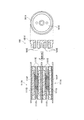
以下において、実施形態に係る香味吸引器について説明する。図1は、実施形態に係る香味吸引器10を示す図である。図2は、実施形態に係る霧化ユニット111を示す図である。香味吸引器10は、燃焼を伴わずに香喫味成分を吸引するための器具であり、非吸口端から吸口端に向かう方向である所定方向Aに沿って延びる形状を有する。[Embodiment]
(Flavor suction device)
The flavor inhaler according to the embodiment will be described below. FIG. 1 is a diagram showing a
図1に示すように、香味吸引器10は、吸引器本体100と、吸口ユニット200とを有する。
As shown in FIG. 1, the
吸引器本体100は、香味吸引器10の本体を構成しており、吸口ユニット200を接続可能な形状を有する。吸引器本体100は、第1本体ユニット110と、第2本体ユニット120とを有する。具体的には、吸引器本体100は、筒体100Xを有しており、吸口ユニット200は、筒体100Xの吸口側端に接続される。
The
第1本体ユニット110は、筒体100Xの一部を構成する第1筒体110Xを有する。第1本体ユニット110は、後述する電池121から供給される電力によって吸引成分源から吸引成分を発生する複数の発生部を有する。実施形態では、第1本体ユニット110は、複数の発生部のそれぞれを有する複数の霧化ユニット111として、第1霧化ユニット111A及び第2霧化ユニット111Bを有する。
The
ここで、第1霧化ユニット111A及び第2霧化ユニット111Bは、同様の構成を有していてもよく、異なる構成を有していてもよい。実施形態では、第1霧化ユニット111A及び第2霧化ユニット111Bは、同様の構成を有するものとして説明を続ける。第1霧化ユニット111A及び第2霧化ユニット111Bは別体のユニットであることが好ましい。第1霧化ユニット111A及び第2霧化ユニット111Bは、筒体100Xに対して着脱可能に構成されていてもよい。第1霧化ユニット111A及び第2霧化ユニット111Bは互いに着脱可能に構成されていてもよい。
Here, the
実施形態では、複数の霧化ユニット111のそれぞれは、図2に示すように、リザーバ111Pと、ウィック111Qと、発生部111Rとを有する。リザーバ111Pは、吸引成分源を貯留する。例えば、リザーバ111Pは、樹脂ウェブ等の材料によって構成される孔質体である。ウィック111Qは、リザーバ111Pに貯留される吸引成分源を保持する。例えば、ウィック111Qは、ガラス繊維によって構成される。発生部111Rは、ウィック111Qによって保持される吸引成分源から吸引成分を発生する。
In the embodiment, each of the plurality of
実施形態では、発生部111Rは、例えば、ウィック111Qに所定ピッチで巻き回される抵抗発熱体によって構成される。抵抗発熱体は、インレット120Aから後述するアウトレット200Aに連通する空気流路を横断するように延びるコイル状の形状を有する。
In the embodiment, the
吸引成分源は、吸引成分を発生させるための材料である。実施形態では、吸引成分源は、吸引成分としてエアロゾルを発生するためのエアロゾル源である。従って、発生部111Rは、吸引成分源(エアロゾル源)を霧化する霧化部の一例である。
The suction component source is a material for generating a suction component. In an embodiment, the source of inhalation component is an aerosol source for generating an aerosol as an inhalation component. Therefore, the
吸引成分源は、例えば、グリセリン又はプロピレングリコールなどの液体(エアロゾル源)である。吸引成分源は、例えば、上述したように、樹脂ウェブ等の材料によって構成される孔質体によって保持される。孔質体は、非たばこ材料によって構成されていてもよく、たばこ材料によって構成されていてもよい。なお、吸引成分源は、香味成分を含有する香味源を含んでいてもよい。或いは、吸引成分源は、香味成分を含有する香味源を含んでいなくてもよい。 The inhalation component source is, for example, a liquid (aerosol source) such as glycerin or propylene glycol. The suction component source is held by the porous body made of a material such as a resin web as described above. The porous body may be made of a non-tobacco material or a tobacco material. In addition, the suction component source may include a flavor source containing a flavor component. Alternatively, the source of inhalation components may be free of flavor sources containing flavor components.
ここで、複数の霧化ユニット111のそれぞれは、図2に示すように、リザーバ111P、ウィック111Q及び発生部111Rに加えて、筒状部材111X、電極111E、リード線111L及び絶縁部材111Iを有する。
Here, each of the plurality of atomizing
筒状部材111Xは、1つの霧化ユニット111内において空気流路を構成する。上述したリザーバ111Pは、空気流路と平行に配置されており、筒状部材111Xによって空気流路と区画される。上述したウィック111Qは、筒状部材111Xを貫通しており、空気流路を横断する。上述した発生部111Rは、筒状部材111Xの空気流路内に配置される。1つの霧化ユニット111に設けられる電極111Eは、空気流路上において発生部111Rに対して上流に設けられる電極対111E1及び空気流路上において発生部111Rに対して下流に設けられる電極対111E2を含む。1つの霧化ユニット111に設けられる電極対111E1及び電極対111E2は、各々が1対の電極(負極及び正極)を構成する。リード線111Lは、1つの霧化ユニット111内において、電極対111E1及び電極対111E2を電気的に接続する電力線である。また、電極対111E1を構成する正極及び負極は、リード線111L及び発生部111Rを介して電気的に接続している。電極対111E2を構成する各電極についても同様である。絶縁部材111Iは、1つの霧化ユニット111内において各電極(負極及び正極)が直接接触しないよう絶縁する。The
このような構成を採用することによって、第1霧化ユニット111A及び第2霧化ユニット111Bが筒体100X内において直列的な位置関係にて配置された際に、第2霧化ユニット111Bの電極対111E1が制御回路50(制御部51)を介さずに第1霧化ユニット111Aの電極対111E2と電気的に接続される。By adopting such a configuration, when the
第2本体ユニット120は、筒体100Xの一部を構成する第2筒体120Xを有する。第2本体ユニット120は、香味吸引器10を駆動するための電池121、香味吸引器10を制御する制御回路(後述する制御回路50)を有する電装ユニットである。電池121や制御回路50は、第2筒体120Xに収容される。電池121は、例えば、リチウムイオン電池である。制御回路50は、例えば、CPU及びメモリによって構成される。実施形態において、第2本体ユニット120は、インレット120Aを有する。インレット120Aから導入される空気は、図2に示すように、霧化ユニット111(発生部111R)に導かれる。言い換えると、複数の霧化ユニット111(発生部111R)は、インレット120Aから後述するアウトレット200Aに連通する空気流路上に設けられる。
The second
吸口ユニット200は、香味吸引器10を構成する吸引器本体100に接続可能に構成される。吸口ユニット200は、ユーザの口腔内に吸引成分を運ぶためのアウトレット200A(吸口)を有する。
The
(エアロゾル流路)
以下において、実施形態に係るエアロゾル流路について説明する。図2は、実施形態に係るエアロゾル流路を説明するための図である。具体的には、図2は、複数の霧化ユニット111の内部構造を示す断面模式図である。(Aerosol flow path)
Hereinafter, the aerosol flow path according to the embodiment will be described. FIG. 2 is a diagram for explaining the aerosol flow path according to the embodiment. Specifically, FIG. 2 is a schematic cross-sectional view showing the internal structure of the plurality of
図2に示すように、香味吸引器10は、霧化ユニット111によって発生するエアロゾルをアウトレット200A側に導くエアロゾル流路140を有する。言い換えると、吸引器本体100に吸口ユニット200が収容された状態において、霧化ユニット111によって発生するエアロゾルをアウトレット200A側に導くエアロゾル流路140が形成される。エアロゾル流路140としては、第1霧化ユニット111Aから発生するエアロゾルを導く第1流路140Aと、第2霧化ユニット111Bから発生するエアロゾルを導く第2流路140Bとを含む。第1霧化ユニット111A及び第2霧化ユニット111Bから発生するエアロゾルは吸口ユニット200を通ってアウトレット200Aに導かれる。
As shown in FIG. 2, the
実施形態では、第1霧化ユニット111A及び第2霧化ユニット111Bは、筒体100X内において直列的な位置関係にて配置される。言い換えると、第2霧化ユニット111Bは、インレット120Aからアウトレット200Aに連通する空気流路上において第1霧化ユニット111Aと比べて下流側に設けられる。
In the embodiment, the
(ブロック構成)
以下において、実施形態に係る香味吸引器のブロック構成について説明する。図3は、実施形態に係る香味吸引器10のブロック構成を示す図である。(Block structure)
The block configuration of the flavor inhaler according to the embodiment will be described below. FIG. 3 is a diagram showing a block configuration of the
図3に示すように、上述した霧化ユニット111(第1霧化ユニット111A及び第2霧化ユニット111B)は、発生部111Rなどに加えて、メモリ111Mを有する。上述した電装ユニットに設けられる制御回路50は、制御部51を有する。
As shown in FIG. 3, the atomization unit 111 (the
メモリ111Mは、霧化ユニット111(ウィック111Q及び発生部111Rなど)の固有パラメータ又は固有パラメータと対応付けられた識別情報を有する情報源の一例である。実施形態では、メモリ111Mは、霧化ユニット111の固有パラメータを記憶する。
The
メモリ111Mは、発生部111Rの電気抵抗値又は発生部111Rの電気抵抗値と対応付けられた識別情報を記憶していてもよい。実施形態では、メモリ111Mは、発生部111Rの電気抵抗値を記憶する。ここで、第1霧化ユニット111Aに設けられたメモリ111Mは、第1霧化ユニット111Aに設けられた発生部111Rの電気抵抗値を記憶しており、第2霧化ユニット111Bに設けられたメモリ111Mは、第2霧化ユニット111Bに設けられた発生部111Rの電気抵抗値を記憶する。
The
メモリ111Mは、リザーバ111Pに貯留される吸引成分源の残量を示す残量情報又は残量情報と対応付けられた識別情報を記憶していてもよい。実施形態では、メモリ111Mは、残量情報を記憶する。
The
ここで、発生部111Rの電気抵抗値は、電気抵抗値の実測値であってもよく、電気抵抗値の推定値であってもよい。具体的には、発生部111Rの両端に測定装置の端子を接続することによって、発生部111Rの電気抵抗値を測定する場合には、発生部111Rの電気抵抗値として実測値を用いることができる。或いは、香味吸引器10に設けられる電源と接続するための電極が発生部111Rに接続されている状態で、発生部111Rに接続された電極に測定装置の端子を接続することによって、発生部111Rの電気抵抗値を測定する場合には、発生部111R以外の部分(電極など)の電気抵抗値を考慮する必要がある。このようなケースにおいては、発生部111R以外の部分(電極など)の電気抵抗値を考慮した推定値を発生部111Rの電気抵抗値として用いることが好ましい。
Here, the electric resistance value of the
また、発生部111Rに供給される電力量の大きさは、発生部111Rの電気抵抗値、発生部111Rに対して印加される電圧の値及び発生部111Rに電圧が印加される時間で定義される。ここでは、発生部111Rに対して印加される電圧の値及び発生部111Rに電圧が印加される時間について主として考える。例えば、発生部111Rに対して連続的に電圧が印加されるケースにおいては、発生部111Rに対して印加される電圧の値の変更によって、発生部111Rに供給される電力量の大きさが変更される。一方で、発生部111Rに対して断続的に電圧が印加されるケース(パルス制御)においては、発生部111Rに対して印加される電圧の値又はデューティ比(すなわち、パルス幅及びパルス間隔)の変更によって、発生部111Rに供給される電力量の大きさが変更される。
The amount of electric power supplied to the
制御部51は、発生部111Rに供給される電力量を制御する。ここで、制御部51は、L=aE+bの式に従って、1回のパフ動作で消費される吸引成分源の量を算出する。
The
E:1回のパフ動作で発生部111Rに供給される電力量
a,b:霧化ユニット111の固有パラメータ
L:1回のパフ動作で消費される吸引成分源の量
詳細には、図4に示すように、発明者等は、鋭意検討の結果、E及びLが線形性の関係を有しており、このような線形性の関係が霧化ユニット111毎に異なることを見出した。図4において、縦軸は、L[mg/puff]であり、横軸は、E[J/puff]である。例えば、霧化ユニットAについては、EがEMIN(A)からEMAX(A)の範囲においてE及びLが線形性の関係を有しており、霧化ユニットAの固有パラメータはaA及びbAである。一方で、霧化ユニットBについては、EがEMIN(B)からEMAX(B)の範囲においてE及びLが線形性の関係を有しており、霧化ユニットBの固有パラメータはaB及びbBである。E: Electric power supplied to the
このように、少なくとも、E及びLの線形性の関係を定義するパラメータa,bは、霧化ユニット111毎に異なっているため、霧化ユニット111の固有パラメータである。また、E及びLが線形性の関係を有する範囲を定義するパラメータEMIN及びEMAXについても、霧化ユニット111毎に異なっているため、霧化ユニット111の固有パラメータと考えてもよい。In this way, at least the parameters a and b that define the linear relationship between E and L are different for each
ここで、霧化ユニット111の固有パラメータは、ウィック111Qの組成、発生部111Rの組成、吸引成分源の組成、霧化ユニット111(ウィック111Q及び発生部111R)の構造などに依存する。従って、固有パラメータは、霧化ユニット111毎に異なることに留意すべきである。
Here, the unique parameter of the
なお、上述したメモリ111Mは、パラメータa,bに加えて、パラメータEMIN及びEMAX又はこれらの固有パラメータと対応付けられた識別情報を記憶していてもよい。但し、Eは、発生部111Rに印加される電圧Vs及び電圧Vsの印加時間Tに影響されるため、EMIN及びEMAXは、電圧Vs、TMIN及びTMAXによって特定されてもよい。すなわち、上述したメモリ111Mは、パラメータa,bに加えて、パラメータ電圧Vs、TMIN及びTMAX又はこれらの固有パラメータと対応付けられた識別情報を記憶していてもよい。なお、電圧Vsは、EMIN及びEMAXをTMIN及びTMAXに置き換えるために用いるパラメータであり、一定値であってもよい。電圧Vsが一定値である場合には、電圧Vsがメモリ111Mに記憶されていなくてもよい。実施形態では、電圧Vsは後述する基準電圧値VCに相当し、メモリ111Mは、パラメータTMIN及びTMAXを記憶する。The
制御部51は、E(T)がEMAX(TMAX)を超えないように、発生部111Rに供給される電力量を制御してもよい。具体的には、例えば、電力量(印加時間)がEMAX(TMAX)に達した場合に、制御部51は発生部111Rへの電力供給を終了する。従って、制御部51は、EがEMAXに達する場合に、L=aEMAX+bの式に従って、1回のパフ動作で消費される吸引成分源の量を算出してもよい。一方で、制御部51は、E(T)がEMIN(TMIN)以下である場合に、L=aEMIN+bの式に従って、1回のパフ動作で消費される吸引成分源の量を算出してもよい。このようなケースにおいて、制御部51は、EがEMINからEMAXの範囲において、L=aE+bの式に従って、1回のパフ動作で消費される吸引成分源の量を算出してもよい。The
ここで、制御部51は、複数の霧化ユニット111のいずれかの電力量(印加時間)がEMAX(TMAX)に達した場合に、制御部51は発生部111Rへの電力供給を終了してもよい。Here, the
実施形態では、制御部51は、Lに基づいて吸引成分源の残量(mg)を推定する。具体的には、制御部51は、1回のパフ動作毎にL(mg)を算出するとともに、メモリ111Mに記憶された残量情報によって示される吸引成分源の残量からLを減算するとともに、メモリ111Mに記憶された残量情報を更新する。
In the embodiment, the
制御部51は、吸引成分源の残量が閾値を下回っている場合に、発生部111Rに対する電力供給を禁止してもよく、若しくは、吸引成分源の残量が閾値を下回っている旨をユーザに通知してもよい。制御部51は、残量情報を取得できない場合に、発生部111Rに対する電力供給を禁止してもよく、若しくは、残量情報を取得できなかった旨をユーザに通知してもよい。ユーザへの通知は、例えば、香味吸引器10に設けられる発光素子の発光によって行われてもよい。
The
ここで、制御部51は、複数の霧化ユニット111のいずれかの吸引成分源の残量が閾値を下回っている場合に、発生部111Rに対する電力供給を禁止してもよく、若しくは、吸引成分源の残量が閾値を下回っている旨をユーザに通知してもよい。制御部51は、複数の霧化ユニット111のいずれかの残量情報を取得できない場合に、発生部111Rに対する電力供給を禁止してもよく、若しくは、残量情報を取得できなかった旨をユーザに通知してもよい。
Here, the
実施形態では、制御部51は、複数の発生部111Rのうち、n番目の発生部111Rに供給される電力量Enについて、En=Vn 2/Rn×Tの式に従って、Enを算出してもよい。Enは、n番目の霧化ユニット111の吸引成分源の残量の推定に用いられてもよい。In an embodiment, the
En:n番目の発生部111RにVnが印加されるケースにおける電力量
Vn:n番目の発生部111Rに印加される電圧値
T:複数の発生部111Rに電圧が印加される時間
Rn:n番目の発生部111Rの電気抵抗値
なお、Vnは、電池の出力電圧値VA、複数の発生部111Rの電気的な接続関係及び各発生部111Rの電気抵抗値に基づいて特定することができる。複数の発生部111Rが並列接続によって電気的に接続されている場合には、Vnは、VAの値であると考えてもよい。複数の発生部111Rが並列接続によって電気的に接続されている場合には、Vnは、各発生部111Rの電気抵抗値によってVAを分割した値であると考えてもよい。E n : electric energy in the case where V n is applied to the n-
また、VA及びTは、制御部51が検出可能な値であり、Rは、メモリ111Mからの読み出しによって制御部51が取得可能な値である。なお、Rは、制御部51によって推定されてもよい。Further, V A and T are values that the
実施形態では、制御部51は、電池の出力電圧値VA及び電池の基準電圧値VCに基づいて補正項D1を算出するとともに、補正項D1に基づいて複数の発生部111Rに供給される電力量を制御する。例えば、制御部51は、パフ動作の開始に応じて、各発生部111Rに供給される電力量を制御するための制御パラメータを設定する。具体的には、制御部51は、発生部111Rに供給される電力量を補正する補正項D1を算出し、算出された補正項D1を設定する。このような構成によれば、ユーザが香味吸引器10を実際に使用したときの回路構成に応じた補正項D1を設定することができる。すなわち、回路構成が変更し得る場合であっても、適切な補正項D1を設定することができる。このようなケースにおいて、制御部51は、パフ動作の開始が検出されてから発生部111Rの温度が吸引成分の沸点に到達するまで(発生部111Rを実質的に駆動するまで)の間に、電池の出力電圧値VAを検出するとともに、検出された電池の出力電圧値VA及び基準電圧値VCに基づいて、検出されたパフ動作に適用する補正項D1を算出する。制御部51は、空気流路に設けられるセンサによって検出された値が所定値を超えた場合に、パフ動作の開始を検出してもよく、発生部111Rを駆動するためのスイッチ(例えば、押しボタン)の押下が行われた場合に、パフ動作の開始を検出してもよい。このようなタイミングで電池の出力電圧値VAの検出及び補正項D1の算出を行うことによって、検出されたパフ動作に適用する補正項D1を適切に算出することができる。In an embodiment, the
上述したパフ動作の開始が検出された後のタイミングでの電池の出力電圧値VAの検出及び補正項D1の算出は、消費電力量の抑制と補正項D1の精度の維持の点で利点を有する。詳細には、上記タイミングでの補正項D1の取得は電池の出力電圧値VAの検出及び補正項D1の算出を一定間隔で行うケース、特に一定間隔が長期間(例えば1分間)である場合と比較して、検出されたパフ動作に適用する補正項D1の精度の低下を抑制することができる。また、電池の出力電圧値VAの検出及び補正項D1の算出を一定間隔で行うケースにおいて、一定間隔が短期間(例えば1秒間)である場合と比較して、電池の出力電圧値VAの検出及び補正項D1の算出に伴う消費電力の増大を抑制することができる。The detection of the output voltage value V A of the battery and the calculation of the correction term D 1 at the timing after the start of the puff operation described above are calculated in terms of suppressing the power consumption and maintaining the accuracy of the correction term D 1. Have advantages. Specifically, the correction term D 1 is acquired at the above timing in the case where the detection of the output voltage value V A of the battery and the calculation of the correction term D 1 are performed at regular intervals, especially when the constant interval is long (for example, 1 minute). It is possible to suppress a decrease in the accuracy of the correction term D 1 applied to the detected puff operation, as compared with a certain case. Further, in the case where the detection of the battery output voltage value V A and the calculation of the correction term D 1 are performed at regular intervals, the battery output voltage value V It is possible to suppress an increase in power consumption due to the detection of A and the calculation of the correction term D 1 .
さらに、補正項D1の算出において、制御部51は、複数回に亘って電池の出力電圧値VAを検出するとともに、検出された複数の出力電圧値VAから出力電圧値VAの代表値を導き出してもよい。出力電圧値VAの代表値は、例えば、複数の出力電圧値VAの平均値である。Further, in the calculation of the correction term D 1, the
VCは、各発生部111Rに印加すべき電圧の値及び電池の種類等に応じて予め定められた値であり、少なくとも電池の終止電圧よりも高い電圧である。電池がリチウムイオン電池である場合には、例えば、基準電圧値VCを3.2Vとすることができる。発生部111Rに対して供給する電力量のレベルを複数レベルで設定することが可能であるケース、すなわち、1回のパフ動作で発生するエアロゾルの量が異なる複数のモードを香味吸引器10が有するケースにおいて、複数の基準電圧値VCが設定されていてもよい。V C is a value that is predetermined according to the value of the voltage to be applied to each
詳細には、電池の出力電圧値VAは、発生部111Rの接続個数及び各発生部111Rの構成(特に、電気抵抗値)によって変動する。このような変動を抑制するために、制御部51は、D1=VC/VAの式に従って、補正項D1を算出する。好ましくは、制御部51は、D1=VC 2/VA 2の式に従って、補正項D1を算出する。制御部51は、E=D1×EAの式に従って、複数の発生部111Rに供給される電力量Eを制御する。言い換えると、制御部51は、E=D1×VA 2/R×Tの式に従って、複数の発生部111Rに供給される電力量Eを制御してもよい。なお、EAは、D1を用いた補正が行われないケースにおいて複数の発生部111Rに供給される電力量である。Specifically, the output voltage value V A of the battery varies depending on the number of
ここで、D1を用いるEの補正方法としては、発生部111Rに印加される電圧の補正(例えば、D1×VA)であってもよく、デューティ比(すなわち、パルス幅及びパルス間隔)の補正(例えば、D1×T)であってもよい。なお、発生部111Rに印加される電圧の補正は、例えば、DC/DCコンバータを用いて実現される。DC/DCコンバータは、降圧コンバータであってもよく、昇圧コンバータであってもよい。Here, the correction method of E using D 1 may be correction of the voltage applied to the
(回路構成)
実施形態に係る複数の霧化ユニット111のそれぞれに設けられる発生部111Rの回路構成について説明する。図5は、実施形態に係る複数の霧化ユニット111のそれぞれに設けられる発生部111Rの回路構成を示す図である。(Circuit configuration)
The circuit configuration of the
図5に示すように、第1霧化ユニット111Aに設けられる発生部111RA及び第2霧化ユニット111Bに設けられる発生部111RBは、並列接続によって電気的に接続される。図5に示すケースでは、第1霧化ユニット111A及び第2霧化ユニット111Bを互いに接続する際に、発生部111RA及び発生部111RBは、接続点(EC1、EC2)を介して電気的に接続される。発生部111RA及び発生部111RBは、接続点(EC1、EC2)を介する電気回路上において制御回路50を経由せずに電気的に接続される。ここで、第1霧化ユニット111Aに備えられた電極対は制御回路50と電気的に接続される。As shown in FIG. 5,
(作用及び効果)
実施形態では、制御部51は、VA及びVCに基づいてD1を算出するとともに、D1に基づいて電力量を制御する。従って、発生部111Rの接続個数や各発生部111Rの構成(特に、電気抵抗値)によって電池の出力電圧値が変動し得る場合であっても、所望量の電力を発生部111RA及び発生部111RBを供給することができる。(Action and effect)
In the embodiment, the
[変更例1]
以下において、実施形態の変更例1について説明する。以下においては、実施形態に対する相違点について主として説明する。[Modification 1]
Hereinafter, a first modification of the embodiment will be described. In the following, differences from the embodiment will be mainly described.
第1に、実施形態では、発生部111Rを構成する抵抗発熱体は、インレット120Aからアウトレット200Aに連通する空気流路を横断するように延びるコイル状の形状を有する。これに対して、変更例1では、発生部111Rを構成する抵抗発熱体は、インレット120Aからアウトレット200Aに連通する空気流路に沿って延びるコイル状の形状を有する。
Firstly, in the embodiment, the resistance heating element forming the generating
第2に、実施形態では、第1霧化ユニット111A及び第2霧化ユニット111Bは、筒体100X内において直列的な位置関係にて配置される。これに対して、変更例1では、第1霧化ユニット111A及び第2霧化ユニット111Bは、筒体100X内において並列的な位置関係にて配置される。
Secondly, in the embodiment, the
具体的には、図6に示すように、第1霧化ユニット111A及び第2霧化ユニット111Bは、筒体100X内において並列的な位置関係にて配置される。香味吸引器10は、複数の霧化ユニット111に加えて、キャップ部材180を有する。複数の霧化ユニット111のそれぞれは、リザーバ111P、ウィック111Q及び発生部111Rに加えて、導電部材111Eを有する。
Specifically, as shown in FIG. 6, the
導電部材111Eは、空気流路を構成する筒状の形状を有しており、1対の電極(負極及び正極)を構成する1対の電極部分を有する。1対の電極部分は、間隔を空けて配置される。上述したリザーバ111Pは、空気流路と平行に配置されており、導電部材111E及びウィック111Qによって空気流路と区画される。上述したウィック111Qは、筒状形状を有しており、空気流路と平行に配置される。ウィック111Qは、1対の電極部分が有する間隔において空気流路に露出する。上述した発生部111Rは、導電部材111Eによって構成される空気流路に沿って延びるコイル状の抵抗発熱体によって構成される。発生部111Rの一端は、1対の電極部分の一方に電気的に接続されており、発生部111Rの他端は、1対の電極部分の他方に電気的に接続される。
The
キャップ部材180は、導電部材181E及び絶縁部材181Xによって構成される。導電部材181Eは、霧化ユニット111の導電部材111Eに電気的に接続される。絶縁部材181Xは、キャップ部材180の下流端面又は側面に導電部材181Eが露出しないように導電部材181Eを被覆する。
The
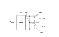
図7に示すように、第1霧化ユニット111Aに設けられる発生部111RA及び第2霧化ユニット111Bに設けられる発生部111RBは、直列接続によって電気的に接続される。図7に示すケースでは、第1霧化ユニット111A及び第2霧化ユニット111Bをキャップ部材180によって接続する際に、発生部111RA及び発生部111RBは、キャップ部材180を介して電気的に接続される。発生部111RA及び発生部111RBは、キャップ部材180(導電部材181E)を介する電気回路上において制御回路50を経由せずに電気的に接続される。ここで、第1霧化ユニット111Aに備えられた一方の電極(キャップ部材180側とは反対側の電極)及び第2霧化ユニット111Bに備えられた一方の電極(キャップ部材180側とは反対側の電極)は制御回路50と電気的に接続される。As shown in FIG. 7,
(作用及び効果)
変更例1においては、制御部51は、VA及びVCに基づいてD1を算出するとともに、D1に基づいて電力量を制御する。従って、各発生部111Rの構成(特に、電気抵抗値)によって電池の出力電圧値が変動し得る場合であっても、所望量の電力を発生部111RA及び発生部111RBを供給することができる。(Action and effect)
In the first modification, the
[変更例2]
以下において、実施形態の変更例2について説明する。以下においては、実施形態に対する相違点について主として説明する。[Modification 2]
Hereinafter, a modified example 2 of the embodiment will be described. In the following, differences from the embodiment will be mainly described.
変更例2では、複数の霧化ユニット111のそれぞれに設けられる発生部111Rの回路構成のバリエーションについて説明する。
In the second modification, variations of the circuit configuration of the
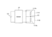
第1に、図8に示すように、第1霧化ユニット111Aに設けられる発生部111RA及び第2霧化ユニット111Bに設けられる発生部111RBは、並列接続によって電気的に接続されてもよい。このようなケースにおいて、発生部111Rを構成する抵抗発熱体は、インレット120Aからアウトレット200Aに連通する空気流路を横断するように延びるコイル状の形状を有することが好ましい。第1霧化ユニット111A及び第2霧化ユニット111Bは、筒体100X内において並列的な位置関係にて配置されることが好ましい。First, as shown in FIG. 8, the generating
このようなケースにおいて、第1霧化ユニット111A及び第2霧化ユニット111Bを互いに接続する際に、発生部111RA及び発生部111RBは、接続点(EC)を介して電気的に接続される。発生部111RA及び発生部111RBは、接続点(EC)を介する電気回路上において制御回路50を経由せずに電気的に接続される。ここで、第1霧化ユニット111Aに備えられた電極対及び第2霧化ユニット111Bに備えられた電極対はいずれも制御回路50と電気的に接続される。第1霧化ユニット111A及び第2霧化ユニット111Bに備えられた同極(+極又は−極)の電極はECを共有する。In such a case, when connecting the
第2に、図9に示すように、第1霧化ユニット111Aに設けられる発生部111RA及び第2霧化ユニット111Bに設けられる発生部111RBは、直列接続によって電気的に接続されてもよい。このようなケースにおいて、発生部111Rを構成する抵抗発熱体は、インレット120Aからアウトレット200Aに連通する空気流路を横断するように延びるコイル状の形状を有することが好ましい。第1霧化ユニット111A及び第2霧化ユニット111Bは、筒体100X内において並列的な位置関係にて配置されることが好ましい。Second, as shown in FIG. 9,
このようなケースにおいて、第1霧化ユニット111A及び第2霧化ユニット111Bを互いに接続する際に、発生部111RA及び発生部111RBは、接続点(EC)を介して電気的に接続される。発生部111RA及び発生部111RBは、接続点(EC)を介する電気回路上において制御回路50を経由せずに電気的に接続される。ここで、第1霧化ユニット111Aに備えられた一方の電極(ECとは反対側の電極)及び第2霧化ユニット111Bに備えられた一方の電極(ECとは反対側の電極)は制御回路50と電気的に接続される。In such a case, when connecting the
第3に、図10に示すように、第1霧化ユニット111Aに設けられる発生部111RA及び第2霧化ユニット111Bに設けられる発生部111RBは、並列接続によって電気的に接続されてもよい。このようなケースにおいて、発生部111Rを構成する抵抗発熱体は、インレット120Aからアウトレット200Aに連通する空気流路に沿って延びるコイル状の形状を有することが好ましい。第1霧化ユニット111A及び第2霧化ユニット111Bは、筒体100X内において並列的な位置関係にて配置されることが好ましい。Third, as shown in FIG. 10, the
このようなケースにおいて、第1霧化ユニット111A及び第2霧化ユニット111Bを互いに接続する際に、発生部111RA及び発生部111RBは、接続点(EC1、EC2)を介して電気的に接続される。発生部111RA及び発生部111RBは、接続点(EC1、EC2)を介する電気回路上において制御回路50を経由せずに電気的に接続される。ここで、接続点(EC1、EC2)は制御回路50と電気的に接続される。In such a case, when connecting the
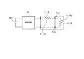
第4に、図11に示すように、第1霧化ユニット111Aに設けられる発生部111RA及び第2霧化ユニット111Bに設けられる発生部111RBは、直列接続によって電気的に接続されてもよい。このようなケースにおいて、発生部111RAを構成する抵抗発熱体は、インレット120Aからアウトレット200Aに連通する空気流路に沿って延びるコイル状の形状を有することが好ましい。一方で、発生部111RBを構成する抵抗発熱体は、インレット120Aからアウトレット200Aに連通する空気流路を横断するように延びるコイル状の形状を有することが好ましい。第1霧化ユニット111A及び第2霧化ユニット111Bは、筒体100X内において直列的な位置関係にて配置されることが好ましい。Fourth, as shown in FIG. 11, the
このようなケースにおいて、第1霧化ユニット111A及び第2霧化ユニット111Bを互いに接続する際に、発生部111RA及び発生部111RBは、接続点(EC1、EC2)を介して電気的に接続される。発生部111RA及び発生部111RBは、接続点(EC1、EC2)を介する電気回路上において制御回路50を経由せずに電気的に接続される。ここで、第1霧化ユニット111Aに備えられた電極対は制御回路50と電気的に接続される。In such a case, when connecting the
[変更例3]
以下において、実施形態の変更例3について説明する。以下においては、実施形態に対する相違点について主として説明する。[Modification 3]
Hereinafter, a modified example 3 of the embodiment will be described. In the following, differences from the embodiment will be mainly described.
変更例3では、複数の霧化ユニット111の位置関係及び発生部111Rを構成する抵抗発熱体の構成のバリエーションについて説明する。
In the third modification, a positional relationship among the plurality of
例えば、図12に示すように、第1本体ユニット110は、第1霧化ユニット111Aを収容する筒体111Xin及び第2霧化ユニット111Bを収容する筒体111Xoutを有する。筒体111Xin及び筒体111Xoutは、同軸の筒状形状を有しており、筒体111Xoutは、筒体111Xinの外側に配置される。具体的には、第1霧化ユニット111Aは、筒体111Xinの内側に配置されており、第2霧化ユニット111Bは、筒体111Xinと筒体111Xoutとの間に配置される。
For example, as shown in FIG. 12, the first
ここで、第1霧化ユニット111A及び第2霧化ユニット111Bは、筒体111Xout内において同軸かつ内外の関係で配置されており、このような位置関係は、並列的な位置関係と考えてよい。第1霧化ユニット111A及び第2霧化ユニット111Bに設けられる発生部111Rは、インレット120Aからアウトレット200Aに連通する空気流路に沿って延びるコイル状の抵抗発熱体によって構成される。なお、第1霧化ユニット111A及び第2霧化ユニット111Bの基本的な構成は、変更例1(図7)と同様であるため、その詳細な説明については省略する。
Here, the
このような構成によれば、第1霧化ユニット111Aから発生するエアロゾルは、筒体111Xinの内側の空間によって構成される空気流路を通る。一方で、第2霧化ユニット111Bから発生するエアロゾルは、筒体111Xinと筒体111Xoutとの間の空間によって構成される空気流路を通る。
According to such a configuration, the aerosol generated from the
[変更例4]
以下において、実施形態の変更例4について説明する。以下においては、実施形態に対する相違点について主として説明する。[Modification 4]
Hereinafter, Modification Example 4 of the embodiment will be described. In the following, differences from the embodiment will be mainly described.
変更例4では、発生部111Rに供給される電力の制御のバリエーションについて説明する。
In the fourth modification, variations of control of the electric power supplied to the
具体的には、制御部51は、上述したように、D1に基づいて補正された電力量(すなわち、D1×EA)に従って、複数の発生部111Rに供給される電力を制御する。このようなケースにおいて、制御部51は、発生部111RA及び発生部111RBに電圧が印加されている状態においてVAを取得するとともに、補正項D1を設定することが好ましい。Specifically, as described above, the
制御部51は、発生部111RA及び発生部111RBが、直列接続によって電気的に接続されるケースにおいて、R1及びR2に基づいて補正項D2を算出するとともに、D2に基づいて発生部111RAに供給される電力量を制御してもよい。例えば、制御部51は、D2=(R1+R2)2/R1 2の式に従って補正項D2を算出する。具体的には、制御部51は、上述したように、D2に基づいて補正された電力量(すなわち、D2×EA)、或いは、D1及びD2に基づいて補正された電力量(すなわち、D1×D2×EA)に従って、発生部111Rに供給される電力を制御する。In a case where the
R1:発生部111RAの電気抵抗値
R2:発生部111RBの電気抵抗値R 1 : Electric resistance value of the
このような構成によれば、発生部111Rの接続個数や各発生部111Rの構成(電気抵抗値)によって電池の出力電圧値VAが変動し得る場合であっても、発生部111RAに供給される電力量を安定化することができる。なお、発生部111RBに供給される電力量を安定化するためには、補正項D2がD2=(R1+R2)2/R2 2の式に従って算出されればよい。According to such a configuration, even if the output voltage value V A of the battery may vary depending on the number of
ここで、第2霧化ユニット111Bが接続されていない状態で第1霧化ユニット111Aの発生部111RAの電気抵抗値を検出できるケース(例えば、実施形態の図5に示すケース)において、制御部51は、発生部111RAの電気抵抗値と、発生部111RA及び発生部111RBの合成抵抗値とを取得してもよい。例えば、制御部51は、第1霧化ユニット111Aが電気的に接続された状態で発生部111RAの電気抵抗値を検出し、第1霧化ユニット111A及び第2霧化ユニット111Bが電気的に接続された状態で合成電気抵抗値を検出する。このような構成によれば、また、第1霧化ユニット111A及び第2霧化ユニット111Bがメモリ111Mを有していなくても、発生部111RA及び発生部111RBの電気抵抗値を取得することが可能である。Here, in a case that can detect the electric resistance value of the
一方で、第2霧化ユニット111Bが接続されていない状態で第1霧化ユニット111Aの発生部111RAの電気抵抗値を検出できないケース(例えば、変更例1の図7に示すケース)において、制御部51は、第1霧化ユニット111Aに設けられたメモリ111Mから発生部111RAの電気抵抗値を読み出すとともに、第1霧化ユニット111A及び第2霧化ユニット111Bが電気的に接続された状態で合成抵抗値を検出する。このような構成によれば、第2霧化ユニット111Bがメモリ111Mを有していなくても、発生部111RA及び発生部111RBの電気抵抗値を取得することが可能である。Meanwhile, in the
さらに、第2霧化ユニット111Bが接続されていない状態で第1霧化ユニット111Aの発生部111RAの電気抵抗値を検出できるか否かによらずに、第1霧化ユニット111A及び第2霧化ユニット111Bの双方がメモリ111Mを有していてもよい。Furthermore, regardless of whether in a state where the
[変更例5]
以下において、実施形態の変更例5について説明する。以下においては、実施形態に対する相違点について主として説明する。[Modification 5]
Hereinafter, a modified example 5 of the embodiment will be described. In the following, differences from the embodiment will be mainly described.
具体的には、実施形態では、メモリ111Mが有する情報は、霧化ユニット111の固有パラメータ(a,b,TMIN,TMAX)、発生部111Rの電気抵抗値(R)及び吸引成分源の残量(Mi)を示す残量情報である。これに対して、変更例1では、メモリ111Mが有する情報は、これらの情報と対応付けられた識別情報である。Specifically, in the embodiment, the information stored in the
このようなケースにおいて、制御部51は、香味吸引器10に接続される外部装置にアクセスして、識別情報に対応する情報を外部装置から取得してもよい。外部装置は、例えば、パーソナルコンピュータ、スマートフォン、タブレットなどである。外部装置に対するアクセス方式は、USB方式であってもよく、Bluetooth(登録商標)やNFC(Near Field Communication)などの無線方式であってもよい。
In such a case, the
或いは、各種のパラメータと対応付けられた識別情報を有する情報源は、霧化ユニット111に設けられるメモリ111Mではなくて、霧化ユニット111とは別に設けられる媒体などであってもよい。媒体は、例えば、識別情報が表された紙媒体(霧化ユニット111の外側面に貼付されるラベル、霧化ユニット111と同梱される説明書、霧化ユニット111を収容する箱などの入れ物など)である。
Alternatively, the information source having the identification information associated with various parameters may be a medium provided separately from the
このようなケースにおいて、制御部51は、媒体に表示された識別情報を読み取る機能(例えば、バーコードリーダ機能)を有しており、媒体から識別情報を読み取る。
In such a case, the
[変更例6]
以下において、実施形態の変更例6について説明する。以下においては、実施形態に対する相違点について主として説明する。[Modification 6]
Hereinafter, a modified example 6 of the embodiment will be described. In the following, differences from the embodiment will be mainly described.
変更例6において、香味吸引器10は、図13に示すように、第2霧化ユニット111Bが第1霧化ユニット111Aに接続されたときに、発生部111RAと電気的に並列接続で導通される発生部111RBを有する。具体的には、香味吸引器10は、発生部111RAと発生部111RBとを並列に電気接続する電気経路302を有し、電気経路302の一部は第2霧化ユニット111Bに設けられている。発生部111RBは、第2霧化ユニット111Bに設けられている。In modification 6,
変更例6では、電気経路302は、第2本体ユニット120(制御回路50)と第1霧化ユニット111Aとを電気的に接続する電気端子300a,300b,301a,301bを含み、第1霧化ユニット111Aと第2霧化ユニット111Bとを電気的に接続する電気端子302a,302b,303a,303bを含む。発生部111RBは発生部111RAと並列に接続されるため、発生部111RAに印加される電圧値(VIN−VOUT)と実質的に等しい電圧が発生部111RBに印加される。In Modification 6, the
香味吸引器10は、発生部111RA及び発生部111RBと直列に電気接続され、既知の電気抵抗値を有する既知抵抗器310を有していてよい。既知抵抗器310は、第2本体ユニット120(制御回路50)に設けられることが好ましい。既知抵抗器310には、発生部111RAの出力電圧VOUTとグランド電極との差に相当する電圧が印加される。
制御部51は、発生部111RAと発生部111RBとの合成抵抗値Rcと、発生部111RAの電気抵抗値R1との差に基づき、第1霧化ユニット111Aと第2霧化ユニット111Bとの接続を検知するよう構成されている。第2霧化ユニット111Bが第1霧化ユニット111Aに接続されていないときに、制御回路50の電気端子300a及び電気端子300bに接続される電気回路の電気抵抗値は、発生部111RAの電気抵抗値R1と実質的に一致する。第2霧化ユニット111Bが第1霧化ユニット111Aに接続されているときに、制御回路50の電気端子300a及び電気端子300bに接続される電気回路の電気抵抗値は、実質的に、発生部111RAの電気抵抗値R1と発生部111RBの電気抵抗値R2との合成抵抗値Rc(<R1)となる。したがって、制御部51は、発生部111RAの電気抵抗値R1と合成抵抗値Rcとの差に基づき、第2霧化ユニット111Bが第1霧化ユニット111Aに接続されているかどうかを検知することができる。
具体的な例として、制御部51は、以下のような手順で、第2霧化ユニット111Bが第1霧化ユニット111Aに接続されているかどうかを検知することができる。まず、第2霧化ユニット111Bが第1霧化ユニット111Aに接続されていないときに、制御部51が発生部111RAの電気抵抗値R1を測定する。電気抵抗値R1は、制御部51のメモリに記憶させておく。制御部51は、所定のタイミングで、電気端子300a及び電気端子300bに接続される電気回路の電気抵抗値を測定する。この電気抵抗値は、第2霧化ユニット111Bが第1霧化ユニット111Aに接続されたときに、上記の合成抵抗値Rc(<R1)となる。制御部51は、電気抵抗値R1よりも小さい電気抵抗値を検出したときに、第2霧化ユニット111Bが第1霧化ユニット111Aに接続されていると判断する。なお、電気抵抗値の測定精度を考慮し、制御部51は、電気抵抗値R1よりも十分に小さい電気抵抗値を検出したときに、第2霧化ユニット111Bが第1霧化ユニット111Aに接続されていると判断してもよい。As a specific example, the
制御部51が、電気端子300a及び電気端子300bに接続される電気回路の電気抵抗値を測定するタイミングは、ユーザが吸引動作を行ったときであることが好ましい。例えば、空気流路内に設けられたセンサが吸引動作を検知したときに、制御部51が電気抵抗値を測定する。
The timing at which the
この代わりに、ユーザが発生部111RAを駆動するスイッチ、例えば押しボタンを押したときに、制御部51が、電気端子300a及び電気端子300bに接続される電気回路の電気抵抗値を測定してもよい。また、制御部51は、所定の時間間隔ごとに、電気端子300a及び電気端子300bに接続される電気回路の電気抵抗値を測定してもよい。Alternatively, switch the user to drive the
また、制御部51は、発生部111RA(又は/及び発生部111RB)の通電を許容しないスリープモード(省電力モード)から発生部111RA(又は/及び発生部111RB)を制御可能なレディモードへ切り替えられたときに、電気端子300a及び電気端子300bに接続される電気回路の電気抵抗値を測定してもよい。スリープモードからレディモードへの切り替えは、例えば、スリープモード中に押しボタンが所定時間以上押されたとき、又はスリープモード中にユーザにより特定パターンの吸い込み動作(例えば、2秒程度の短時間での吸い込み動作を所定時間内で3回行う等)が行われたときに実行される。In addition, the
さらに、香味吸引器10がユーザ認証機能を有している場合、制御部51は、ユーザ認証のための動作が行われたタイミングで、電気端子300a及び電気端子300bに接続される電気回路の電気抵抗値を測定してもよい。ユーザ認証は、例えば、空気流路内に設けられたセンサによってユーザによる吸引動作の特徴を検出することによって行うことができる。もっとも、ユーザ認証の方法は、この例に限定されるものではない。
Furthermore, when the
なお、電気端子300a及び電気端子300bに接続される電気回路の電気抵抗値は、以下のように測定することができる。まず、発生部111RAへの入力電圧VINと、発生部111RAの出力電圧VOUT(=既知抵抗器310の入力電圧)と、を測定する。電気端子300a及び電気端子300bに接続される電気回路の電気抵抗値Rは、電圧値VIN,VOUTと既知抵抗器310の電気抵抗値R3を用いて、以下の式により算出される:
R=((VIN−VOUT)/VOUT)×R3。The electric resistance value of the electric circuit connected to the
R=((V IN −V OUT )/V OUT )×R 3 .
第2霧化ユニット111Bが第1霧化ユニット111Aに接続されていない場合には、上式から、実質的に発生部111RAの電気抵抗値R1が算出される。また、第2霧化ユニット111Bが第1霧化ユニット111Aに接続されている場合には、上式から、実質的に合成抵抗値Rcが算出される。When the
上記のように、制御部51は、既知抵抗器310の電気抵抗値R3を用いて合成抵抗値Rcを推定するよう構成されていることが好ましい。図13に示す既知抵抗器310の配置は一例である。既知抵抗器310は、発生部111RAの電気抵抗値R1、発生部111RAと発生部111RBとの合成抵抗値Rcを測定可能であれば、電気回路上の任意の位置に配置されていてよい。なお、既知抵抗器310の電気抵抗値Rは、10mΩ〜100mΩの範囲であってよい。As described above, the
制御部51は、第1霧化ユニット111Aと第2霧化ユニット111Bとの接続を検知した後に、発生部111RA(又は/及び発生部111RB)へ供給する電力量の制御、又は香味吸引器10に備えられた報知手段の報知制御を行ってもよい。報知手段としては、例えば、発光素子、音声出力デバイス、Haptics等の感覚フィードバックデバイス等が挙げられる。報知手段として感覚フィードバックデバイスを用いる場合には、例えば発振素子等を具備し、振動をユーザに伝達することによって報知を行っても良い。After detecting the connection between the
制御部51は、合成抵抗値Rcと発生部111RAの電気抵抗値R1との差が所定の第1閾値以下の場合に発生部111RAへ電力供給を禁止するよう構成されていてよい。これにより、第2霧化ユニット111Bが第1霧化ユニット111Aに接続されていないときに、香味吸引器10を使用できないようにすることができる。また、正規の第2霧化ユニット111Bとは異なり、発生部111RBを有していない非正規の部品が第1霧化ユニット111Aに接続されたときに、発生部111RAへ電力を供給しないようにすることで、非正規品の使用を禁止することができる。
また、制御部51は、合成抵抗値Rcと発生部111RAの電気抵抗値R1との差が所定の第2閾値(前述の第1閾値よりも大きい値)以上の場合に発生部111RAへ電力供給を禁止するよう構成されていてもよい。これにより、電気端子302aと電気端子302bとの間で短絡が生じたときに、発生部111RAへの電力供給を停止することができる。Further, the
さらに、制御部51は、合成抵抗値Rcと発生部111RAの電気抵抗値R1との差が上記の所定の第1閾値以下の場合と、上記の所定の第2閾値以上の場合に、発生部111RAへの電力供給を停止してもよい。これにより、正規品の発生部111RBの電気抵抗値とは全く異なる電気抵抗値を有する抵抗器を備えた非正規品が第1霧化ユニット111Aに接続された場合に、発生部111RAへ電力供給を禁止することができる。Further, the
上述したケースでは、制御部51は、第2霧化ユニット111Bが第1霧化ユニット111Aに接続されていないときに、発生部111RAの電気抵抗値R1を測定するとともに、測定された電気抵抗値R1を制御部51のメモリに記憶させる。しかしながら、変更例6はこれに限定されるものではない。発生部111RAの電気抵抗値R1は、第1霧化ユニット111Aのメモリ111Mに記憶されており、制御部51は、発生部111RAの電気抵抗値R1を測定せずに、第1霧化ユニット111Aのメモリ111Mから発生部111RAの電気抵抗値R1を読み出してもよい。Electrical In the above case, the
さらに、発生部111RAの電気抵抗値R1が第1霧化ユニット111Aのメモリ111Mに記憶されており、発生部111RBの電気抵抗値R2が第2霧化ユニット111Bのメモリ111Mに記憶されていてもよい。このようなケースにおいて、制御部51は、メモリ111Mから読み出された電気抵抗値R1及びR2に基づいて発生部111RA及び発生部111RBの合成抵抗値Rcを算出してもよい。制御部51は、電気端子300a及び電気端子300bに接続される電気回路の電気抵抗値の測定値(すなわち、上述した合成抵抗値Rcの測定値)と発生部111RAの電気抵抗値R1との比較結果ではなく、第1霧化ユニット111Aのメモリ111Mから読み出された電気抵抗値R1と合成抵抗値Rcの算出値との比較結果に基づいて、第2霧化ユニット111Bが第1霧化ユニット111Aに接続されているか否かを判定してもよい。例えば、制御部51は、第1霧化ユニット111Aのメモリ111Mから読み出された電気抵抗値R1と合成抵抗値Rcの算出値との差が所定値以上である場合に、第2霧化ユニット111Bが第1霧化ユニット111Aに接続されていると判定する。このようなケースにおいて、既知抵抗器310は設けられていなくてもよい。Further, generating
[その他の実施形態]
本発明は上述した実施形態によって説明したが、この開示の一部をなす論述及び図面は、この発明を限定するものであると理解すべきではない。この開示から当業者には様々な代替実施形態、実施例及び運用技術が明らかとなろう。[Other Embodiments]
Although the present invention has been described by the above-described embodiments, it should not be understood that the description and drawings forming a part of this disclosure limit the present invention. From this disclosure, various alternative embodiments, examples, and operation techniques will be apparent to those skilled in the art.
実施形態では、第1霧化ユニット111Aに設けられる発生部111R(発生部111RA)は、電池から供給される電力によって第1吸引成分源から第1吸引成分を発生させる第1発生部の一例である。同様に、第2霧化ユニット111Bに設けられる発生部111R(発生部111RB)は、電池から供給される電力によって第2吸引成分源から第2吸引成分を発生させる第2発生部の一例である。しかしながら、実施形態はこれに限定されるものではない。具体的には、第1発生部及び第2発生部は、抵抗発熱体によって構成されていなくてもよい。例えば、第1発生部及び第2発生部は、加熱を伴わずに超音波霧化によってエアロゾルを発生させる部材であってもよい。或いは、第1発生部及び第2発生部は、霧化を伴わずに吸引成分源の加熱によって吸引成分を発生させる部材であってもよい。第1発生部及び第2発生部が吸引成分を発生させる方式(霧化方式や加熱方式)は互いに異なっていてもよい。例えば、第1発生部及び第2発生部を構成する抵抗発熱体の電気抵抗値は互いに異なっていてもよい。第1発生部及び第2発生部から発生する吸引成分の量は互いに異なっていてもよい。第1発生部及び第2発生部のいずれか一方からエアロゾルが発生しなくてもよい。In embodiments, generator provided in the
実施形態では、第1吸引成分源及び第2吸引成分源は、エアロゾル源である。しかしながら、実施形態はこれに限定されるものではない。具体的には、第1吸引成分源及び第2吸引成分源は、エアロゾル源を含まずにメンソールなどの香味成分を含む部材であってもよい。第1吸引成分源及び第2吸引成分源の組成や種類は互いに異なっていてもよい。第1吸引成分源及び第2吸引成分源は、液体であってもよく、固体であってもよい。第1吸引成分源及び第2吸引成分源の一方が液体であって、第1吸引成分源及び第2吸引成分源の他方が固体であってもよい。 In an embodiment, the first and second aspirating component sources are aerosol sources. However, the embodiment is not limited to this. Specifically, the first suction component source and the second suction component source may be members that do not include an aerosol source but include a flavor component such as menthol. The composition and type of the first suction component source and the second suction component source may be different from each other. The first suction component source and the second suction component source may be liquid or solid. One of the first suction component source and the second suction component source may be a liquid, and the other of the first suction component source and the second suction component source may be a solid.
実施形態では、第1吸引成分源は、第1発生部を有するユニットに組み込まれており、第2吸引成分源は、第2発生部を有するユニットに組み込まれている。しかしながら、実施形態はこれに限定されるものではない。第1吸引成分源は、第1発生部を有するユニットとは別体の貯留ユニットに貯留されてもよく、第2吸引成分源は、第2発生部を有するユニットとは別体の貯留ユニットに貯留されてもよい。 In the embodiment, the first suction component source is incorporated in the unit having the first generation unit, and the second suction component source is incorporated in the unit having the second generation unit. However, the embodiment is not limited to this. The first suction component source may be stored in a storage unit that is separate from the unit that includes the first generation unit, and the second suction component source may be stored in a storage unit that is separate from the unit that includes the second generation unit. It may be stored.
実施形態では、第1霧化ユニット111A及び第2霧化ユニット111Bは、筒体100Xに対して着脱可能に構成されてもよい。第1霧化ユニット111A及び第2霧化ユニット111Bは互いに着脱可能に構成されてもよい。しかしながら、実施形態はこれに限定されるものではない。第1霧化ユニット111A及び第2霧化ユニット111Bは、筒体100Xに対して固定的に取り付けられてもよい。第1霧化ユニット111A及び第2霧化ユニット111Bは一体のユニットであってもよい。
In the embodiment, the
Claims (16)
前記電池から供給される電力によって第1吸引成分源から第1吸引成分を発生させる第1発生部と、
前記電池から供給される電力によって第2吸引成分源から第2吸引成分を発生させる第2発生部と、
前記第1発生部及び前記第2発生部に供給される電力量を制御する制御部とを備え、
前記第1発生部及び前記第2発生部は、インレットからアウトレットに連通する空気流路上に設けられており、
前記第1発生部及び前記第2発生部は、並列接続又は直列接続によって電気的に接続されており、
前記電池の出力電圧値は、VAによって表され、予備加熱段階において前記第1発生部及び前記第2発生部に電力が供給された状態で測定された値であり、
前記電池の基準電圧値は、VCによって表され、
前記第1発生部及び前記第2発生部に供給される電力量の補正項は、D1によって表され、
前記制御部は、前記VA及び前記VCに基づいて前記D1を算出するとともに、前記D1に基づいて前記電力量を制御することを特徴とする香味吸引器。 A battery that stores electricity
A first generation unit that generates a first suction component from a first suction component source by electric power supplied from the battery;
A second generator for generating a second suction component from a second suction component source by the electric power supplied from the battery;
A control unit that controls the amount of electric power supplied to the first generation unit and the second generation unit;
The first generating portion and the second generating portion are provided on an air flow path communicating from the inlet to the outlet,
The first generator and the second generator are electrically connected by parallel connection or series connection,
The output voltage value of the battery is represented by VA , and is a value measured in a state in which power is supplied to the first generating unit and the second generating unit in a preheating step ,
The reference voltage value of the battery is represented by V C ,
A correction term for the amount of electric power supplied to the first generator and the second generator is represented by D 1 .
The flavor suction device, wherein the control unit calculates the D 1 based on the V A and the V C and controls the electric energy based on the D 1 .
前記第2発生部を少なくとも有する第2ユニットとを備え、
前記第1ユニット及び前記第2ユニットは別体であることを特徴とする請求項1乃至請求項4のいずれかに記載の香味吸引器。 A first unit having at least the first generating section;
A second unit having at least the second generator,
The flavor inhaler according to any one of claims 1 to 4, wherein the first unit and the second unit are separate bodies.
前記第1発生部及び前記第2発生部は、前記接続点又は前記導電部材を介する電気回路上において前記制御部を経由せずに電気的に接続されることを特徴とする請求項5又は請求項6に記載の香味吸引器。 The first generation unit and the second generation unit are electrically connected via a connection point or a conductive member when connecting the first unit and the second unit,
The first generation unit and the second generation unit are electrically connected without passing through the control unit on an electric circuit via the connection point or the conductive member. Item 7. The flavor inhaler according to Item 6.
前記第1発生部及び前記第2発生部の少なくともいずれかは、前記エアロゾル源を霧化する霧化部であることを特徴とする請求項1乃至請求項7のいずれかに記載の香味吸引器。 At least one of the first suction component source and the second suction component source is an aerosol source,
At least one of said 1st generation part and said 2nd generation part is an atomization part which atomizes said aerosol source, The flavor inhaler in any one of Claim 1 thru|or 7 characterized by the above-mentioned. ..
前記制御部は、前記第1発生部の電気抵抗値と、前記第1発生部及び前記第2発生部の合成抵抗値とを取得することを特徴とする請求項1乃至請求項11のいずれかに記載の香味吸引器。 The first generating portion and the second generating portion are composed of resistance heating elements,
12. The control unit acquires an electric resistance value of the first generation unit and a combined resistance value of the first generation unit and the second generation unit, according to any one of claims 1 to 11. The flavor inhaler described in.
前記第1発生部及び前記第2発生部は、抵抗発熱体によって構成されており、
前記第1発生部の電気抵抗値は、R1によって表され、
前記第2発生部の電気抵抗値は、R2によって表され、
前記第1発生部に供給される電力量の補正項は、D2によって表され、
前記R1及び前記R2に基づいて前記D2を算出するとともに、前記D2に基づいて前記第1発生部に供給される電力量を制御する制御部を備えることを特徴とする請求項1乃至請求項12のいずれかに記載の香味吸引器。 The first generator and the second generator are electrically connected by a series connection,
The first generating portion and the second generating portion are composed of resistance heating elements,
The electrical resistance value of the first generator is represented by R 1 ,
The electric resistance value of the second generator is represented by R 2 .
Correction term of the amount of power supplied to the first generating portion is represented by D 2,
The control unit that calculates the D 2 based on the R 1 and the R 2 and that controls the amount of power supplied to the first generation unit based on the D 2 is provided. 13. The flavor inhaler according to claim 12.
前記第1発生部の電気抵抗値又は前記第1発生部の電気抵抗値と対応付けられた識別情報を有する情報源を備えることを特徴とする請求項1乃至請求項14のいずれかに記載の香味吸引器。 The first generator is composed of a resistance heating element,
The information source according to claim 1, further comprising: an information source having identification information associated with the electric resistance value of the first generation unit or the electric resistance value of the first generation unit. Flavor suction device.
Applications Claiming Priority (1)
| Application Number | Priority Date | Filing Date | Title |
|---|---|---|---|
| PCT/JP2016/054487 WO2017141358A1 (en) | 2016-02-16 | 2016-02-16 | Flavor inhaler |
Publications (2)
| Publication Number | Publication Date |
|---|---|
| JPWO2017141358A1 JPWO2017141358A1 (en) | 2018-09-13 |
| JP6738357B2 true JP6738357B2 (en) | 2020-08-12 |
Family
ID=59625681
Family Applications (1)
| Application Number | Title | Priority Date | Filing Date |
|---|---|---|---|
| JP2017567864A Active JP6738357B2 (en) | 2016-02-16 | 2016-02-16 | Flavor suction device |
Country Status (9)
| Country | Link |
|---|---|
| US (1) | US10881148B2 (en) |
| EP (1) | EP3400815A4 (en) |
| JP (1) | JP6738357B2 (en) |
| KR (1) | KR102225228B1 (en) |
| CN (1) | CN108601404B (en) |
| CA (1) | CA3013420C (en) |
| EA (1) | EA038385B1 (en) |
| HK (1) | HK1257316A1 (en) |
| WO (1) | WO2017141358A1 (en) |
Families Citing this family (41)
| Publication number | Priority date | Publication date | Assignee | Title |
|---|---|---|---|---|
| US20160345631A1 (en) | 2005-07-19 | 2016-12-01 | James Monsees | Portable devices for generating an inhalable vapor |
| US10279934B2 (en) | 2013-03-15 | 2019-05-07 | Juul Labs, Inc. | Fillable vaporizer cartridge and method of filling |
| US10159282B2 (en) | 2013-12-23 | 2018-12-25 | Juul Labs, Inc. | Cartridge for use with a vaporizer device |
| USD842536S1 (en) | 2016-07-28 | 2019-03-05 | Juul Labs, Inc. | Vaporizer cartridge |
| US10058129B2 (en) | 2013-12-23 | 2018-08-28 | Juul Labs, Inc. | Vaporization device systems and methods |
| USD825102S1 (en) | 2016-07-28 | 2018-08-07 | Juul Labs, Inc. | Vaporizer device with cartridge |
| US20160366947A1 (en) | 2013-12-23 | 2016-12-22 | James Monsees | Vaporizer apparatus |
| EP3498115B1 (en) | 2013-12-23 | 2021-09-01 | Juul Labs International Inc. | Vaporization device systems |
| US10076139B2 (en) | 2013-12-23 | 2018-09-18 | Juul Labs, Inc. | Vaporizer apparatus |
| AU2015357509B2 (en) | 2014-12-05 | 2021-05-20 | Juul Labs, Inc. | Calibrated dose control |
| DE202017007467U1 (en) | 2016-02-11 | 2021-12-08 | Juul Labs, Inc. | Fillable vaporizer cartridge |
| CO2018009342A2 (en) | 2016-02-11 | 2018-09-20 | Juul Labs Inc | Secure fixing cartridges for vaporizing devices |
| US10405582B2 (en) | 2016-03-10 | 2019-09-10 | Pax Labs, Inc. | Vaporization device with lip sensing |
| USD849996S1 (en) | 2016-06-16 | 2019-05-28 | Pax Labs, Inc. | Vaporizer cartridge |
| USD836541S1 (en) | 2016-06-23 | 2018-12-25 | Pax Labs, Inc. | Charging device |
| USD851830S1 (en) | 2016-06-23 | 2019-06-18 | Pax Labs, Inc. | Combined vaporizer tamp and pick tool |
| WO2018102703A1 (en) | 2016-12-02 | 2018-06-07 | Vmr Products Llc | Combination vaporizer |
| USD887632S1 (en) | 2017-09-14 | 2020-06-16 | Pax Labs, Inc. | Vaporizer cartridge |
| DE102017121664A1 (en) | 2017-09-19 | 2019-03-21 | Hauni Maschinenbau Gmbh | Component part and base part for an inhaler, and method for manufacturing the same |
| GB201717498D0 (en) | 2017-10-24 | 2017-12-06 | British American Tobacco Investments Ltd | Aerosol provision device |
| GB201717496D0 (en) | 2017-10-24 | 2017-12-06 | British American Tobacco Investments Ltd | A cartridge for an aerosol provision device |
| GB201719578D0 (en) * | 2017-11-24 | 2018-01-10 | British American Tobacco Investments Ltd | Apparatus, system and method for generating an inhalable medium |
| US10813384B2 (en) | 2017-12-29 | 2020-10-27 | Altria Client Services Llc | Electronic vaping device having formulation level indicator |
| WO2019148038A1 (en) | 2018-01-26 | 2019-08-01 | Juul Labs, Inc. | Charging case assembly |
| JP6532076B1 (en) * | 2018-10-26 | 2019-06-19 | 日本たばこ産業株式会社 | Main unit of aerosol generating device, aerosol generating device and non-combustion suction device |
| CN111096489A (en) * | 2018-10-26 | 2020-05-05 | 日本烟草产业株式会社 | Aerosol generating device, main unit thereof, and non-combustion type suction device |
| JP7158557B2 (en) * | 2019-02-27 | 2022-10-21 | 日本たばこ産業株式会社 | FLAVOR COMPONENT GENERATION CONTROL DEVICE, FLAVOR COMPONENT GENERATION DEVICE, CONTROL METHOD AND PROGRAM |
| KR102360135B1 (en) * | 2019-08-08 | 2022-02-08 | 주식회사 케이티앤지 | Aerosol generating system |
| WO2021059384A1 (en) * | 2019-09-25 | 2021-04-01 | 日本たばこ産業株式会社 | Battery unit, aerosol generation device, information processing method, and program |
| FR3106472A1 (en) * | 2020-01-27 | 2021-07-30 | Enovap | DEVICE AND METHOD FOR ADJUSTING A QUANTITY OF ACTIVE SUBSTANCE INHALED BY A USER |
| KR102479092B1 (en) * | 2020-02-24 | 2022-12-19 | 주식회사 케이티앤지 | Aerosol generating device |
| KR102478152B1 (en) * | 2020-03-02 | 2022-12-15 | 주식회사 케이티앤지 | Aerosol generating device and system |
| EP4108109A1 (en) * | 2020-06-25 | 2022-12-28 | Japan Tobacco Inc. | Inhaling device, control method, and program |
| WO2021260894A1 (en) * | 2020-06-25 | 2021-12-30 | 日本たばこ産業株式会社 | Inhaling device, control method, and program |
| JP2022015340A (en) * | 2020-07-08 | 2022-01-21 | 日本たばこ産業株式会社 | Control unit of aerosol generation device |
| JP2022015342A (en) * | 2020-07-08 | 2022-01-21 | 日本たばこ産業株式会社 | Control unit of aerosol generation device |
| JP2022015341A (en) * | 2020-07-08 | 2022-01-21 | 日本たばこ産業株式会社 | Control unit of aerosol generation device |
| JP6890205B1 (en) * | 2020-11-20 | 2021-06-18 | 日本たばこ産業株式会社 | Power supply unit of aerosol generator |
| CN112369689A (en) * | 2020-11-27 | 2021-02-19 | 云南中烟工业有限责任公司 | Aerosol generating device capable of realizing bidirectional suction |
| WO2022113040A1 (en) * | 2020-11-29 | 2022-06-02 | Ditch Labs Inc. | Vaporization device with two liquid reservoirs |
| WO2024013927A1 (en) * | 2022-07-14 | 2024-01-18 | 日本たばこ産業株式会社 | Inhalation device and control method |
Family Cites Families (17)
| Publication number | Priority date | Publication date | Assignee | Title |
|---|---|---|---|---|
| US5372148A (en) * | 1993-02-24 | 1994-12-13 | Philip Morris Incorporated | Method and apparatus for controlling the supply of energy to a heating load in a smoking article |
| US6040560A (en) * | 1996-10-22 | 2000-03-21 | Philip Morris Incorporated | Power controller and method of operating an electrical smoking system |
| JP2949114B1 (en) * | 1998-08-04 | 1999-09-13 | 日本たばこ産業株式会社 | Electric flavor generation article heating control device |
| JP5041016B2 (en) | 2010-03-01 | 2012-10-03 | 東京エレクトロン株式会社 | Heat treatment apparatus, heat treatment method and storage medium |
| US9301547B2 (en) * | 2010-11-19 | 2016-04-05 | Huizhou Kimree Technology Co., Ltd. Shenzhen Branch | Electronic cigarette, electronic cigarette smoke capsule and atomization device thereof |
| RU2616556C2 (en) * | 2011-12-08 | 2017-04-17 | Филип Моррис Продактс С.А. | Aerosol generating device with air ventilation nozzles |
| MY172044A (en) * | 2012-02-22 | 2019-11-12 | Altria Client Services Llc | Electronic smoking article and improved heater element |
| WO2013147492A1 (en) * | 2012-03-26 | 2013-10-03 | 주식회사 엔브라이트 | Atomization control unit and a portable atomizing appratus having the same |
| US10004259B2 (en) * | 2012-06-28 | 2018-06-26 | Rai Strategic Holdings, Inc. | Reservoir and heater system for controllable delivery of multiple aerosolizable materials in an electronic smoking article |
| GB2504077A (en) * | 2012-07-16 | 2014-01-22 | Nicoventures Holdings Ltd | Electronic smoking device |
| CA2882840C (en) * | 2012-08-31 | 2018-06-26 | Kimree Hi-Tech Inc. | Electronic cigarette |
| US9423152B2 (en) * | 2013-03-15 | 2016-08-23 | R. J. Reynolds Tobacco Company | Heating control arrangement for an electronic smoking article and associated system and method |
| GB2519101A (en) * | 2013-10-09 | 2015-04-15 | Nicoventures Holdings Ltd | Electronic vapour provision system |
| US11013872B2 (en) * | 2013-12-19 | 2021-05-25 | Philip Morris Products S.A. | Aerosol-generating system for generating and controlling the quantity of nicotine salt particles |
| WO2015106381A1 (en) * | 2014-01-14 | 2015-07-23 | 吉瑞高新科技股份有限公司 | Electronic cigarette vaporizer and electronic cigarette |
| CN107087390A (en) * | 2014-05-13 | 2017-08-22 | 富特姆4有限公司 | Electronics fume extracting device and data exchange application |
| CN203986125U (en) * | 2014-07-17 | 2014-12-10 | 深圳市康尔科技有限公司 | A kind of electronic cigarette |
-
2016
- 2016-02-16 CA CA3013420A patent/CA3013420C/en active Active
- 2016-02-16 KR KR1020187024876A patent/KR102225228B1/en active IP Right Grant
- 2016-02-16 EP EP16890500.8A patent/EP3400815A4/en active Pending
- 2016-02-16 WO PCT/JP2016/054487 patent/WO2017141358A1/en active Application Filing
- 2016-02-16 EA EA201891849A patent/EA038385B1/en unknown
- 2016-02-16 JP JP2017567864A patent/JP6738357B2/en active Active
- 2016-02-16 CN CN201680081554.6A patent/CN108601404B/en active Active
-
2018
- 2018-08-16 US US16/104,016 patent/US10881148B2/en active Active
- 2018-12-22 HK HK18116473.2A patent/HK1257316A1/en unknown
Also Published As
| Publication number | Publication date |
|---|---|
| EP3400815A4 (en) | 2019-12-11 |
| CA3013420C (en) | 2020-07-14 |
| CN108601404A (en) | 2018-09-28 |
| EP3400815A1 (en) | 2018-11-14 |
| EA038385B1 (en) | 2021-08-19 |
| WO2017141358A1 (en) | 2017-08-24 |
| US10881148B2 (en) | 2021-01-05 |
| HK1257316A1 (en) | 2019-10-18 |
| KR102225228B1 (en) | 2021-03-08 |
| US20180352863A1 (en) | 2018-12-13 |
| CN108601404B (en) | 2021-11-09 |
| KR20180111880A (en) | 2018-10-11 |
| EA201891849A1 (en) | 2019-01-31 |
| JPWO2017141358A1 (en) | 2018-09-13 |
| CA3013420A1 (en) | 2017-08-24 |
Similar Documents
| Publication | Publication Date | Title |
|---|---|---|
| JP6738357B2 (en) | Flavor suction device | |
| US10966465B2 (en) | Non-combustion-type flavor inhaler, method, program, and recording medium | |
| JP7379225B2 (en) | Power supply unit for aerosol inhaler, control method and program for power supply unit for aerosol inhaler | |
| KR102022814B1 (en) | Non-combustion type flavor inhaler and atomization unit | |
| KR102636203B1 (en) | Inhalation component generating device, control circuit, and control method and control program of inhalation component generating device | |
| KR102183438B1 (en) | Inhalation component generating device, control circuit, and control method of inhalation component generating device | |
| RU2747604C1 (en) | Power supply unit for aerosol inhaler | |
| JP2020058308A (en) | Inhalation component generating device, control circuit, and control method and control program of inhalation component generating device | |
| JP6630866B1 (en) | Suction component generation device, control circuit, control method of suction component generation device, and control program | |
| JP7307842B2 (en) | Suction component generator | |
| JP6630867B1 (en) | Suction component generation device, control circuit, control method of suction component generation device, and control program | |
| EP4111890A1 (en) | Aerosol generation device alerting of a forthcoming capillary element drying | |
| JP2022533501A (en) | Aerosol generator and method of controlling same | |
| EA040434B1 (en) | NON-BURNING TYPE AROMATIC INHALATOR, METHOD, PROGRAM AND RECORDING MEDIA |
Legal Events
| Date | Code | Title | Description |
|---|---|---|---|
| A621 | Written request for application examination |
Free format text: JAPANESE INTERMEDIATE CODE: A621 Effective date: 20180502 |
|
| RD03 | Notification of appointment of power of attorney |
Free format text: JAPANESE INTERMEDIATE CODE: A7423 Effective date: 20190104 |
|
| RD04 | Notification of resignation of power of attorney |
Free format text: JAPANESE INTERMEDIATE CODE: A7424 Effective date: 20190116 |
|
| A131 | Notification of reasons for refusal |
Free format text: JAPANESE INTERMEDIATE CODE: A131 Effective date: 20190618 |
|
| A521 | Request for written amendment filed |
Free format text: JAPANESE INTERMEDIATE CODE: A523 Effective date: 20190805 |
|
| A02 | Decision of refusal |
Free format text: JAPANESE INTERMEDIATE CODE: A02 Effective date: 20200130 |
|
| A521 | Request for written amendment filed |
Free format text: JAPANESE INTERMEDIATE CODE: A523 Effective date: 20200416 |
|
| A911 | Transfer to examiner for re-examination before appeal (zenchi) |
Free format text: JAPANESE INTERMEDIATE CODE: A911 Effective date: 20200423 |
|
| TRDD | Decision of grant or rejection written | ||
| A01 | Written decision to grant a patent or to grant a registration (utility model) |
Free format text: JAPANESE INTERMEDIATE CODE: A01 Effective date: 20200625 |
|
| A61 | First payment of annual fees (during grant procedure) |
Free format text: JAPANESE INTERMEDIATE CODE: A61 Effective date: 20200717 |
|
| R150 | Certificate of patent or registration of utility model |
Ref document number: 6738357 Country of ref document: JP Free format text: JAPANESE INTERMEDIATE CODE: R150 |
|
| R250 | Receipt of annual fees |
Free format text: JAPANESE INTERMEDIATE CODE: R250 |