RU2753553C2 - Rechargeable lithium-ion battery for aerosol delivery device - Google Patents
Rechargeable lithium-ion battery for aerosol delivery device Download PDFInfo
- Publication number
- RU2753553C2 RU2753553C2 RU2019115275A RU2019115275A RU2753553C2 RU 2753553 C2 RU2753553 C2 RU 2753553C2 RU 2019115275 A RU2019115275 A RU 2019115275A RU 2019115275 A RU2019115275 A RU 2019115275A RU 2753553 C2 RU2753553 C2 RU 2753553C2
- Authority
- RU
- Russia
- Prior art keywords
- delivery device
- aerosol delivery
- microprocessor
- lithium
- power source
- Prior art date
Links
- 239000000443 aerosol Substances 0.000 title claims abstract description 178
- HBBGRARXTFLTSG-UHFFFAOYSA-N Lithium ion Chemical compound [Li+] HBBGRARXTFLTSG-UHFFFAOYSA-N 0.000 title claims abstract description 67
- 229910001416 lithium ion Inorganic materials 0.000 title claims abstract description 67
- 239000000203 mixture Substances 0.000 claims abstract description 39
- 239000002243 precursor Substances 0.000 claims abstract description 37
- OKTJSMMVPCPJKN-UHFFFAOYSA-N Carbon Chemical compound [C] OKTJSMMVPCPJKN-UHFFFAOYSA-N 0.000 claims abstract description 21
- 229910052799 carbon Inorganic materials 0.000 claims abstract description 17
- 239000003792 electrolyte Substances 0.000 claims abstract description 16
- 239000000126 substance Substances 0.000 claims abstract description 12
- 229910003002 lithium salt Inorganic materials 0.000 claims abstract description 10
- 159000000002 lithium salts Chemical class 0.000 claims abstract description 10
- 239000002904 solvent Substances 0.000 claims abstract description 10
- BVKZGUZCCUSVTD-UHFFFAOYSA-L Carbonate Chemical compound [O-]C([O-])=O BVKZGUZCCUSVTD-UHFFFAOYSA-L 0.000 claims abstract description 7
- 238000010438 heat treatment Methods 0.000 claims description 32
- PEDCQBHIVMGVHV-UHFFFAOYSA-N Glycerine Chemical compound OCC(O)CO PEDCQBHIVMGVHV-UHFFFAOYSA-N 0.000 claims description 10
- -1 lithium hexafluorophosphate Chemical group 0.000 claims description 9
- 229910052744 lithium Inorganic materials 0.000 claims description 8
- 238000001514 detection method Methods 0.000 claims description 6
- SNICXCGAKADSCV-JTQLQIEISA-N (-)-Nicotine Chemical compound CN1CCC[C@H]1C1=CC=CN=C1 SNICXCGAKADSCV-JTQLQIEISA-N 0.000 claims description 5
- 235000011187 glycerol Nutrition 0.000 claims description 5
- 229960002715 nicotine Drugs 0.000 claims description 5
- SNICXCGAKADSCV-UHFFFAOYSA-N nicotine Natural products CN1CCCC1C1=CC=CN=C1 SNICXCGAKADSCV-UHFFFAOYSA-N 0.000 claims description 5
- 230000015572 biosynthetic process Effects 0.000 claims description 3
- 230000000391 smoking effect Effects 0.000 abstract description 15
- 230000000694 effects Effects 0.000 abstract description 2
- 241000208125 Nicotiana Species 0.000 description 17
- 235000002637 Nicotiana tabacum Nutrition 0.000 description 17
- 239000000463 material Substances 0.000 description 16
- 239000000047 product Substances 0.000 description 14
- 235000019504 cigarettes Nutrition 0.000 description 9
- 238000012546 transfer Methods 0.000 description 9
- 239000007788 liquid Substances 0.000 description 8
- 230000007246 mechanism Effects 0.000 description 8
- 238000000034 method Methods 0.000 description 8
- 235000019506 cigar Nutrition 0.000 description 7
- 230000001007 puffing effect Effects 0.000 description 7
- 239000003570 air Substances 0.000 description 6
- 238000004891 communication Methods 0.000 description 6
- 239000003571 electronic cigarette Substances 0.000 description 6
- 230000006870 function Effects 0.000 description 6
- 230000000007 visual effect Effects 0.000 description 6
- YXTPWUNVHCYOSP-UHFFFAOYSA-N bis($l^{2}-silanylidene)molybdenum Chemical compound [Si]=[Mo]=[Si] YXTPWUNVHCYOSP-UHFFFAOYSA-N 0.000 description 5
- 238000002485 combustion reaction Methods 0.000 description 5
- 230000001276 controlling effect Effects 0.000 description 5
- 238000005516 engineering process Methods 0.000 description 5
- 238000005259 measurement Methods 0.000 description 5
- 239000000779 smoke Substances 0.000 description 5
- 229910052782 aluminium Inorganic materials 0.000 description 4
- 239000003990 capacitor Substances 0.000 description 4
- 229920002981 polyvinylidene fluoride Polymers 0.000 description 4
- 230000035807 sensation Effects 0.000 description 4
- 235000019615 sensations Nutrition 0.000 description 4
- DNIAPMSPPWPWGF-UHFFFAOYSA-N Propylene glycol Chemical compound CC(O)CO DNIAPMSPPWPWGF-UHFFFAOYSA-N 0.000 description 3
- 230000001133 acceleration Effects 0.000 description 3
- XAGFODPZIPBFFR-UHFFFAOYSA-N aluminium Chemical compound [Al] XAGFODPZIPBFFR-UHFFFAOYSA-N 0.000 description 3
- 239000003575 carbonaceous material Substances 0.000 description 3
- 239000000919 ceramic Substances 0.000 description 3
- 238000013461 design Methods 0.000 description 3
- 239000012530 fluid Substances 0.000 description 3
- 229910002804 graphite Inorganic materials 0.000 description 3
- 239000010439 graphite Substances 0.000 description 3
- 229910052751 metal Inorganic materials 0.000 description 3
- 239000002184 metal Substances 0.000 description 3
- 229910021344 molybdenum silicide Inorganic materials 0.000 description 3
- 230000002441 reversible effect Effects 0.000 description 3
- 239000011877 solvent mixture Substances 0.000 description 3
- 239000000758 substrate Substances 0.000 description 3
- 239000002250 absorbent Substances 0.000 description 2
- 230000002745 absorbent Effects 0.000 description 2
- 239000012080 ambient air Substances 0.000 description 2
- 239000011262 electrochemically active material Substances 0.000 description 2
- 239000000796 flavoring agent Substances 0.000 description 2
- 235000019634 flavors Nutrition 0.000 description 2
- 235000011389 fruit/vegetable juice Nutrition 0.000 description 2
- 239000007789 gas Substances 0.000 description 2
- 238000007429 general method Methods 0.000 description 2
- 238000010348 incorporation Methods 0.000 description 2
- 230000003993 interaction Effects 0.000 description 2
- 238000012986 modification Methods 0.000 description 2
- 230000004048 modification Effects 0.000 description 2
- 229910021343 molybdenum disilicide Inorganic materials 0.000 description 2
- 230000000737 periodic effect Effects 0.000 description 2
- 239000004033 plastic Substances 0.000 description 2
- 229920003023 plastic Polymers 0.000 description 2
- 238000000197 pyrolysis Methods 0.000 description 2
- 239000002096 quantum dot Substances 0.000 description 2
- 230000000717 retained effect Effects 0.000 description 2
- 239000007787 solid Substances 0.000 description 2
- 241000894007 species Species 0.000 description 2
- 239000010935 stainless steel Substances 0.000 description 2
- 229910001220 stainless steel Inorganic materials 0.000 description 2
- 230000008016 vaporization Effects 0.000 description 2
- NOOLISFMXDJSKH-KXUCPTDWSA-N (-)-Menthol Chemical compound CC(C)[C@@H]1CC[C@@H](C)C[C@H]1O NOOLISFMXDJSKH-KXUCPTDWSA-N 0.000 description 1
- RYGMFSIKBFXOCR-UHFFFAOYSA-N Copper Chemical compound [Cu] RYGMFSIKBFXOCR-UHFFFAOYSA-N 0.000 description 1
- NOOLISFMXDJSKH-UHFFFAOYSA-N DL-menthol Natural products CC(C)C1CCC(C)CC1O NOOLISFMXDJSKH-UHFFFAOYSA-N 0.000 description 1
- OIFBSDVPJOWBCH-UHFFFAOYSA-N Diethyl carbonate Chemical compound CCOC(=O)OCC OIFBSDVPJOWBCH-UHFFFAOYSA-N 0.000 description 1
- KMTRUDSVKNLOMY-UHFFFAOYSA-N Ethylene carbonate Chemical compound O=C1OCCO1 KMTRUDSVKNLOMY-UHFFFAOYSA-N 0.000 description 1
- 229910013870 LiPF 6 Inorganic materials 0.000 description 1
- WHXSMMKQMYFTQS-UHFFFAOYSA-N Lithium Chemical compound [Li] WHXSMMKQMYFTQS-UHFFFAOYSA-N 0.000 description 1
- 230000009471 action Effects 0.000 description 1
- 239000004480 active ingredient Substances 0.000 description 1
- 229910045601 alloy Inorganic materials 0.000 description 1
- 239000000956 alloy Substances 0.000 description 1
- 235000019568 aromas Nutrition 0.000 description 1
- 230000009286 beneficial effect Effects 0.000 description 1
- 239000006227 byproduct Substances 0.000 description 1
- 238000010276 construction Methods 0.000 description 1
- 239000011889 copper foil Substances 0.000 description 1
- IEJIGPNLZYLLBP-UHFFFAOYSA-N dimethyl carbonate Chemical compound COC(=O)OC IEJIGPNLZYLLBP-UHFFFAOYSA-N 0.000 description 1
- 238000007599 discharging Methods 0.000 description 1
- 239000003814 drug Substances 0.000 description 1
- 238000012377 drug delivery Methods 0.000 description 1
- 238000001704 evaporation Methods 0.000 description 1
- 230000008020 evaporation Effects 0.000 description 1
- 239000000835 fiber Substances 0.000 description 1
- 239000006260 foam Substances 0.000 description 1
- 238000009472 formulation Methods 0.000 description 1
- 239000003205 fragrance Substances 0.000 description 1
- 239000007792 gaseous phase Substances 0.000 description 1
- 230000020169 heat generation Effects 0.000 description 1
- 230000006266 hibernation Effects 0.000 description 1
- 239000004615 ingredient Substances 0.000 description 1
- 150000002500 ions Chemical class 0.000 description 1
- 230000007257 malfunction Effects 0.000 description 1
- 238000004519 manufacturing process Methods 0.000 description 1
- 229940041616 menthol Drugs 0.000 description 1
- 229910001120 nichrome Inorganic materials 0.000 description 1
- 238000004806 packaging method and process Methods 0.000 description 1
- 239000002245 particle Substances 0.000 description 1
- 239000013618 particulate matter Substances 0.000 description 1
- 230000000704 physical effect Effects 0.000 description 1
- 239000004417 polycarbonate Substances 0.000 description 1
- 229920000515 polycarbonate Polymers 0.000 description 1
- 230000001105 regulatory effect Effects 0.000 description 1
- 150000003839 salts Chemical class 0.000 description 1
- 230000035939 shock Effects 0.000 description 1
- 230000007958 sleep Effects 0.000 description 1
- 238000001179 sorption measurement Methods 0.000 description 1
- 125000006850 spacer group Chemical group 0.000 description 1
- 239000007921 spray Substances 0.000 description 1
- 150000005846 sugar alcohols Polymers 0.000 description 1
- 239000000725 suspension Substances 0.000 description 1
- 235000019640 taste Nutrition 0.000 description 1
- 230000009466 transformation Effects 0.000 description 1
- 238000000844 transformation Methods 0.000 description 1
- 238000009834 vaporization Methods 0.000 description 1
Images


Classifications
-
- A—HUMAN NECESSITIES
- A24—TOBACCO; CIGARS; CIGARETTES; SIMULATED SMOKING DEVICES; SMOKERS' REQUISITES
- A24F—SMOKERS' REQUISITES; MATCH BOXES; SIMULATED SMOKING DEVICES
- A24F40/00—Electrically operated smoking devices; Component parts thereof; Manufacture thereof; Maintenance or testing thereof; Charging means specially adapted therefor
- A24F40/40—Constructional details, e.g. connection of cartridges and battery parts
-
- A—HUMAN NECESSITIES
- A24—TOBACCO; CIGARS; CIGARETTES; SIMULATED SMOKING DEVICES; SMOKERS' REQUISITES
- A24F—SMOKERS' REQUISITES; MATCH BOXES; SIMULATED SMOKING DEVICES
- A24F40/00—Electrically operated smoking devices; Component parts thereof; Manufacture thereof; Maintenance or testing thereof; Charging means specially adapted therefor
- A24F40/90—Arrangements or methods specially adapted for charging batteries thereof
- A24F40/95—Arrangements or methods specially adapted for charging batteries thereof structurally associated with cases
-
- H—ELECTRICITY
- H01—ELECTRIC ELEMENTS
- H01M—PROCESSES OR MEANS, e.g. BATTERIES, FOR THE DIRECT CONVERSION OF CHEMICAL ENERGY INTO ELECTRICAL ENERGY
- H01M4/00—Electrodes
- H01M4/02—Electrodes composed of, or comprising, active material
- H01M4/36—Selection of substances as active materials, active masses, active liquids
- H01M4/58—Selection of substances as active materials, active masses, active liquids of inorganic compounds other than oxides or hydroxides, e.g. sulfides, selenides, tellurides, halogenides or LiCoFy; of polyanionic structures, e.g. phosphates, silicates or borates
- H01M4/583—Carbonaceous material, e.g. graphite-intercalation compounds or CFx
- H01M4/587—Carbonaceous material, e.g. graphite-intercalation compounds or CFx for inserting or intercalating light metals
-
- A—HUMAN NECESSITIES
- A24—TOBACCO; CIGARS; CIGARETTES; SIMULATED SMOKING DEVICES; SMOKERS' REQUISITES
- A24B—MANUFACTURE OR PREPARATION OF TOBACCO FOR SMOKING OR CHEWING; TOBACCO; SNUFF
- A24B15/00—Chemical features or treatment of tobacco; Tobacco substitutes, e.g. in liquid form
- A24B15/10—Chemical features of tobacco products or tobacco substitutes
- A24B15/16—Chemical features of tobacco products or tobacco substitutes of tobacco substitutes
- A24B15/167—Chemical features of tobacco products or tobacco substitutes of tobacco substitutes in liquid or vaporisable form, e.g. liquid compositions for electronic cigarettes
-
- A—HUMAN NECESSITIES
- A24—TOBACCO; CIGARS; CIGARETTES; SIMULATED SMOKING DEVICES; SMOKERS' REQUISITES
- A24F—SMOKERS' REQUISITES; MATCH BOXES; SIMULATED SMOKING DEVICES
- A24F40/00—Electrically operated smoking devices; Component parts thereof; Manufacture thereof; Maintenance or testing thereof; Charging means specially adapted therefor
- A24F40/40—Constructional details, e.g. connection of cartridges and battery parts
- A24F40/42—Cartridges or containers for inhalable precursors
-
- A—HUMAN NECESSITIES
- A24—TOBACCO; CIGARS; CIGARETTES; SIMULATED SMOKING DEVICES; SMOKERS' REQUISITES
- A24F—SMOKERS' REQUISITES; MATCH BOXES; SIMULATED SMOKING DEVICES
- A24F40/00—Electrically operated smoking devices; Component parts thereof; Manufacture thereof; Maintenance or testing thereof; Charging means specially adapted therefor
- A24F40/40—Constructional details, e.g. connection of cartridges and battery parts
- A24F40/46—Shape or structure of electric heating means
-
- A—HUMAN NECESSITIES
- A24—TOBACCO; CIGARS; CIGARETTES; SIMULATED SMOKING DEVICES; SMOKERS' REQUISITES
- A24F—SMOKERS' REQUISITES; MATCH BOXES; SIMULATED SMOKING DEVICES
- A24F40/00—Electrically operated smoking devices; Component parts thereof; Manufacture thereof; Maintenance or testing thereof; Charging means specially adapted therefor
- A24F40/50—Control or monitoring
- A24F40/53—Monitoring, e.g. fault detection
-
- A—HUMAN NECESSITIES
- A24—TOBACCO; CIGARS; CIGARETTES; SIMULATED SMOKING DEVICES; SMOKERS' REQUISITES
- A24F—SMOKERS' REQUISITES; MATCH BOXES; SIMULATED SMOKING DEVICES
- A24F40/00—Electrically operated smoking devices; Component parts thereof; Manufacture thereof; Maintenance or testing thereof; Charging means specially adapted therefor
- A24F40/60—Devices with integrated user interfaces
-
- A—HUMAN NECESSITIES
- A24—TOBACCO; CIGARS; CIGARETTES; SIMULATED SMOKING DEVICES; SMOKERS' REQUISITES
- A24F—SMOKERS' REQUISITES; MATCH BOXES; SIMULATED SMOKING DEVICES
- A24F40/00—Electrically operated smoking devices; Component parts thereof; Manufacture thereof; Maintenance or testing thereof; Charging means specially adapted therefor
- A24F40/90—Arrangements or methods specially adapted for charging batteries thereof
-
- A—HUMAN NECESSITIES
- A61—MEDICAL OR VETERINARY SCIENCE; HYGIENE
- A61M—DEVICES FOR INTRODUCING MEDIA INTO, OR ONTO, THE BODY; DEVICES FOR TRANSDUCING BODY MEDIA OR FOR TAKING MEDIA FROM THE BODY; DEVICES FOR PRODUCING OR ENDING SLEEP OR STUPOR
- A61M11/00—Sprayers or atomisers specially adapted for therapeutic purposes
- A61M11/04—Sprayers or atomisers specially adapted for therapeutic purposes operated by the vapour pressure of the liquid to be sprayed or atomised
- A61M11/041—Sprayers or atomisers specially adapted for therapeutic purposes operated by the vapour pressure of the liquid to be sprayed or atomised using heaters
- A61M11/042—Sprayers or atomisers specially adapted for therapeutic purposes operated by the vapour pressure of the liquid to be sprayed or atomised using heaters electrical
-
- A—HUMAN NECESSITIES
- A61—MEDICAL OR VETERINARY SCIENCE; HYGIENE
- A61M—DEVICES FOR INTRODUCING MEDIA INTO, OR ONTO, THE BODY; DEVICES FOR TRANSDUCING BODY MEDIA OR FOR TAKING MEDIA FROM THE BODY; DEVICES FOR PRODUCING OR ENDING SLEEP OR STUPOR
- A61M15/00—Inhalators
- A61M15/06—Inhaling appliances shaped like cigars, cigarettes or pipes
-
- H—ELECTRICITY
- H01—ELECTRIC ELEMENTS
- H01M—PROCESSES OR MEANS, e.g. BATTERIES, FOR THE DIRECT CONVERSION OF CHEMICAL ENERGY INTO ELECTRICAL ENERGY
- H01M10/00—Secondary cells; Manufacture thereof
- H01M10/05—Accumulators with non-aqueous electrolyte
- H01M10/052—Li-accumulators
- H01M10/0525—Rocking-chair batteries, i.e. batteries with lithium insertion or intercalation in both electrodes; Lithium-ion batteries
-
- H—ELECTRICITY
- H01—ELECTRIC ELEMENTS
- H01M—PROCESSES OR MEANS, e.g. BATTERIES, FOR THE DIRECT CONVERSION OF CHEMICAL ENERGY INTO ELECTRICAL ENERGY
- H01M10/00—Secondary cells; Manufacture thereof
- H01M10/05—Accumulators with non-aqueous electrolyte
- H01M10/056—Accumulators with non-aqueous electrolyte characterised by the materials used as electrolytes, e.g. mixed inorganic/organic electrolytes
- H01M10/0564—Accumulators with non-aqueous electrolyte characterised by the materials used as electrolytes, e.g. mixed inorganic/organic electrolytes the electrolyte being constituted of organic materials only
- H01M10/0566—Liquid materials
- H01M10/0568—Liquid materials characterised by the solutes
-
- H—ELECTRICITY
- H01—ELECTRIC ELEMENTS
- H01M—PROCESSES OR MEANS, e.g. BATTERIES, FOR THE DIRECT CONVERSION OF CHEMICAL ENERGY INTO ELECTRICAL ENERGY
- H01M10/00—Secondary cells; Manufacture thereof
- H01M10/05—Accumulators with non-aqueous electrolyte
- H01M10/056—Accumulators with non-aqueous electrolyte characterised by the materials used as electrolytes, e.g. mixed inorganic/organic electrolytes
- H01M10/0564—Accumulators with non-aqueous electrolyte characterised by the materials used as electrolytes, e.g. mixed inorganic/organic electrolytes the electrolyte being constituted of organic materials only
- H01M10/0566—Liquid materials
- H01M10/0569—Liquid materials characterised by the solvents
-
- H—ELECTRICITY
- H01—ELECTRIC ELEMENTS
- H01M—PROCESSES OR MEANS, e.g. BATTERIES, FOR THE DIRECT CONVERSION OF CHEMICAL ENERGY INTO ELECTRICAL ENERGY
- H01M10/00—Secondary cells; Manufacture thereof
- H01M10/42—Methods or arrangements for servicing or maintenance of secondary cells or secondary half-cells
- H01M10/425—Structural combination with electronic components, e.g. electronic circuits integrated to the outside of the casing
- H01M10/4264—Structural combination with electronic components, e.g. electronic circuits integrated to the outside of the casing with capacitors
-
- H—ELECTRICITY
- H01—ELECTRIC ELEMENTS
- H01M—PROCESSES OR MEANS, e.g. BATTERIES, FOR THE DIRECT CONVERSION OF CHEMICAL ENERGY INTO ELECTRICAL ENERGY
- H01M16/00—Structural combinations of different types of electrochemical generators
- H01M16/003—Structural combinations of different types of electrochemical generators of fuel cells with other electrochemical devices, e.g. capacitors, electrolysers
-
- H—ELECTRICITY
- H02—GENERATION; CONVERSION OR DISTRIBUTION OF ELECTRIC POWER
- H02J—CIRCUIT ARRANGEMENTS OR SYSTEMS FOR SUPPLYING OR DISTRIBUTING ELECTRIC POWER; SYSTEMS FOR STORING ELECTRIC ENERGY
- H02J7/00—Circuit arrangements for charging or depolarising batteries or for supplying loads from batteries
- H02J7/0063—Circuit arrangements for charging or depolarising batteries or for supplying loads from batteries with circuits adapted for supplying loads from the battery
-
- H—ELECTRICITY
- H02—GENERATION; CONVERSION OR DISTRIBUTION OF ELECTRIC POWER
- H02J—CIRCUIT ARRANGEMENTS OR SYSTEMS FOR SUPPLYING OR DISTRIBUTING ELECTRIC POWER; SYSTEMS FOR STORING ELECTRIC ENERGY
- H02J7/00—Circuit arrangements for charging or depolarising batteries or for supplying loads from batteries
- H02J7/007—Regulation of charging or discharging current or voltage
-
- H—ELECTRICITY
- H02—GENERATION; CONVERSION OR DISTRIBUTION OF ELECTRIC POWER
- H02J—CIRCUIT ARRANGEMENTS OR SYSTEMS FOR SUPPLYING OR DISTRIBUTING ELECTRIC POWER; SYSTEMS FOR STORING ELECTRIC ENERGY
- H02J7/00—Circuit arrangements for charging or depolarising batteries or for supplying loads from batteries
- H02J7/34—Parallel operation in networks using both storage and other dc sources, e.g. providing buffering
- H02J7/342—The other DC source being a battery actively interacting with the first one, i.e. battery to battery charging
-
- H—ELECTRICITY
- H02—GENERATION; CONVERSION OR DISTRIBUTION OF ELECTRIC POWER
- H02J—CIRCUIT ARRANGEMENTS OR SYSTEMS FOR SUPPLYING OR DISTRIBUTING ELECTRIC POWER; SYSTEMS FOR STORING ELECTRIC ENERGY
- H02J7/00—Circuit arrangements for charging or depolarising batteries or for supplying loads from batteries
- H02J7/34—Parallel operation in networks using both storage and other dc sources, e.g. providing buffering
- H02J7/345—Parallel operation in networks using both storage and other dc sources, e.g. providing buffering using capacitors as storage or buffering devices
-
- A—HUMAN NECESSITIES
- A24—TOBACCO; CIGARS; CIGARETTES; SIMULATED SMOKING DEVICES; SMOKERS' REQUISITES
- A24F—SMOKERS' REQUISITES; MATCH BOXES; SIMULATED SMOKING DEVICES
- A24F40/00—Electrically operated smoking devices; Component parts thereof; Manufacture thereof; Maintenance or testing thereof; Charging means specially adapted therefor
- A24F40/10—Devices using liquid inhalable precursors
-
- A—HUMAN NECESSITIES
- A61—MEDICAL OR VETERINARY SCIENCE; HYGIENE
- A61M—DEVICES FOR INTRODUCING MEDIA INTO, OR ONTO, THE BODY; DEVICES FOR TRANSDUCING BODY MEDIA OR FOR TAKING MEDIA FROM THE BODY; DEVICES FOR PRODUCING OR ENDING SLEEP OR STUPOR
- A61M2205/00—General characteristics of the apparatus
- A61M2205/50—General characteristics of the apparatus with microprocessors or computers
-
- A—HUMAN NECESSITIES
- A61—MEDICAL OR VETERINARY SCIENCE; HYGIENE
- A61M—DEVICES FOR INTRODUCING MEDIA INTO, OR ONTO, THE BODY; DEVICES FOR TRANSDUCING BODY MEDIA OR FOR TAKING MEDIA FROM THE BODY; DEVICES FOR PRODUCING OR ENDING SLEEP OR STUPOR
- A61M2205/00—General characteristics of the apparatus
- A61M2205/82—Internal energy supply devices
- A61M2205/8206—Internal energy supply devices battery-operated
-
- H—ELECTRICITY
- H01—ELECTRIC ELEMENTS
- H01M—PROCESSES OR MEANS, e.g. BATTERIES, FOR THE DIRECT CONVERSION OF CHEMICAL ENERGY INTO ELECTRICAL ENERGY
- H01M10/00—Secondary cells; Manufacture thereof
- H01M10/42—Methods or arrangements for servicing or maintenance of secondary cells or secondary half-cells
- H01M2010/4292—Aspects relating to capacity ratio of electrodes/electrolyte or anode/cathode
-
- H—ELECTRICITY
- H01—ELECTRIC ELEMENTS
- H01M—PROCESSES OR MEANS, e.g. BATTERIES, FOR THE DIRECT CONVERSION OF CHEMICAL ENERGY INTO ELECTRICAL ENERGY
- H01M2220/00—Batteries for particular applications
- H01M2220/30—Batteries in portable systems, e.g. mobile phone, laptop
-
- H—ELECTRICITY
- H02—GENERATION; CONVERSION OR DISTRIBUTION OF ELECTRIC POWER
- H02J—CIRCUIT ARRANGEMENTS OR SYSTEMS FOR SUPPLYING OR DISTRIBUTING ELECTRIC POWER; SYSTEMS FOR STORING ELECTRIC ENERGY
- H02J2207/00—Indexing scheme relating to details of circuit arrangements for charging or depolarising batteries or for supplying loads from batteries
- H02J2207/20—Charging or discharging characterised by the power electronics converter
-
- Y—GENERAL TAGGING OF NEW TECHNOLOGICAL DEVELOPMENTS; GENERAL TAGGING OF CROSS-SECTIONAL TECHNOLOGIES SPANNING OVER SEVERAL SECTIONS OF THE IPC; TECHNICAL SUBJECTS COVERED BY FORMER USPC CROSS-REFERENCE ART COLLECTIONS [XRACs] AND DIGESTS
- Y02—TECHNOLOGIES OR APPLICATIONS FOR MITIGATION OR ADAPTATION AGAINST CLIMATE CHANGE
- Y02E—REDUCTION OF GREENHOUSE GAS [GHG] EMISSIONS, RELATED TO ENERGY GENERATION, TRANSMISSION OR DISTRIBUTION
- Y02E60/00—Enabling technologies; Technologies with a potential or indirect contribution to GHG emissions mitigation
- Y02E60/10—Energy storage using batteries
-
- Y—GENERAL TAGGING OF NEW TECHNOLOGICAL DEVELOPMENTS; GENERAL TAGGING OF CROSS-SECTIONAL TECHNOLOGIES SPANNING OVER SEVERAL SECTIONS OF THE IPC; TECHNICAL SUBJECTS COVERED BY FORMER USPC CROSS-REFERENCE ART COLLECTIONS [XRACs] AND DIGESTS
- Y02—TECHNOLOGIES OR APPLICATIONS FOR MITIGATION OR ADAPTATION AGAINST CLIMATE CHANGE
- Y02E—REDUCTION OF GREENHOUSE GAS [GHG] EMISSIONS, RELATED TO ENERGY GENERATION, TRANSMISSION OR DISTRIBUTION
- Y02E60/00—Enabling technologies; Technologies with a potential or indirect contribution to GHG emissions mitigation
- Y02E60/13—Energy storage using capacitors
-
- Y—GENERAL TAGGING OF NEW TECHNOLOGICAL DEVELOPMENTS; GENERAL TAGGING OF CROSS-SECTIONAL TECHNOLOGIES SPANNING OVER SEVERAL SECTIONS OF THE IPC; TECHNICAL SUBJECTS COVERED BY FORMER USPC CROSS-REFERENCE ART COLLECTIONS [XRACs] AND DIGESTS
- Y02—TECHNOLOGIES OR APPLICATIONS FOR MITIGATION OR ADAPTATION AGAINST CLIMATE CHANGE
- Y02E—REDUCTION OF GREENHOUSE GAS [GHG] EMISSIONS, RELATED TO ENERGY GENERATION, TRANSMISSION OR DISTRIBUTION
- Y02E60/00—Enabling technologies; Technologies with a potential or indirect contribution to GHG emissions mitigation
- Y02E60/30—Hydrogen technology
- Y02E60/50—Fuel cells
Abstract
Description
ОБЛАСТЬ ТЕХНИКИFIELD OF TECHNOLOGY
Настоящее изобретение относится к устройствам доставки аэрозоля, таким как курительные изделия, и более конкретно к устройствам доставки аэрозоля, в которых может использоваться электрически вырабатываемое тепло для получения аэрозоля (например, к курительным изделиям, обычно называемым электронными сигаретами). Курительные изделия могут быть выполнены с возможностью нагрева предшественника аэрозоля, который может включать материалы, которые могут быть изготовлены или получены из табака, или иным образом включать табак, при этом указанный предшественник способен образовывать вдыхаемое вещество для потребления человеком.The present invention relates to aerosol delivery devices such as smoking articles, and more particularly to aerosol delivery devices that can use electrically generated heat to produce an aerosol (eg, smoking articles commonly referred to as electronic cigarettes). The smoking article may be configured to heat an aerosol precursor, which may include materials that may be made from or derived from tobacco, or otherwise include tobacco, wherein the precursor is capable of forming an respirable substance for human consumption.
УРОВЕНЬ ТЕХНИКИLEVEL OF TECHNOLOGY
На протяжении многих лет было предложено множество устройств в качестве усовершенствования или альтернативы курительным продуктам, для использования которых требуется сжигание табака. Подразумевается, что многие из указанных устройств были разработаны для обеспечения ощущений, связанных с курением сигарет, сигар или курительных трубок, но без доставки значительного количества продуктов неполного сгорания и пиролиза, которые являются результатом сжигания табака. С этой целью предложено множество альтернативных курительных продуктов, генераторов аромата и медицинских ингаляторов, которые используют электрическую энергию для испарения или нагревания легкоиспаряемого материала или пытаются обеспечить ощущения курения сигарет, сигар или курительных трубок без существенного сжигания табака. См., например, различные альтернативные курительные изделия, устройства доставки аэрозоля и источники для вырабатывания тепла, изложенные в уровне техники как описанном в патенте США №8,881,737 под авторством Collett и др., в публикации заявки на патент США №2013/0255702 под авторством Griffith Jr. и др., в публикации заявки на патент США №2014/0000638 под авторством Sebastian и др., в публикации заявки на патент США №2014/0096781 под авторством Sears и др., в публикации заявки на патент США №2014/0096782 под авторством Ampolini и др., в публикации заявки на патент США №2015/0059780 под авторством Davis и др., и в заявке на патент США №15/222,615 под авторством Watson и др., с датой подачи 28 июля 2016, все из которых включены в настоящий документ посредством ссылки. См. также, например, различные варианты реализации продуктов и конфигураций нагрева, описанные в разделах «уровень техники» в патентах США №5,388,594 под авторством Counts и др. и №8,079,371 под авторством Robinson и др., которые включены в настоящий документ посредством ссылки.Over the years, many devices have been proposed as improvements or alternatives to smoking products that require the combustion of tobacco to be used. It is understood that many of these devices have been designed to provide the sensations associated with smoking cigarettes, cigars or pipes, but without delivering significant amounts of incomplete combustion and pyrolysis products that result from the burning of tobacco. To this end, a variety of alternative smoking products, aroma generators and medical inhalers have been proposed that use electrical energy to vaporize or heat volatile material, or attempt to provide the sensation of smoking cigarettes, cigars, or pipes without substantially burning tobacco. See, for example, the various alternative smoking articles, aerosol delivery devices, and heat generating sources set forth in the art as described in US Pat. No. 8,881,737 to Collett et al., US Patent Application Publication No. 2013/0255702 to Griffith Jr. and others, in US Patent Application Publication No. 2014/0000638 by Sebastian et al., in US Patent Application Publication No. 2014/0096781 by Sears et al., in US Patent Application Publication No. 2014/0096782 by Ampolini et al., In US Patent Application Publication No. 2015/0059780 by Davis et al. And US Patent Application No. 15 / 222,615 by Watson et al., Filing Jul. 28, 2016, all of which are incorporated to this document by reference. See also, for example, the various product implementations and heating configurations described in the prior art sections in US Pat. Nos. 5,388,594 to Counts et al. And No. 8,079,371 to Robinson et al., Which are incorporated herein by reference.
Однако предпочтительным является обеспечение устройств доставки аэрозоля с усовершенствованным электронным оборудованием, например, таким, которое может повысить удобство использования устройств.However, it is preferable to provide aerosol delivery devices with improved electronic equipment, such as, for example, that can improve the usability of the devices.
Раскрытие сущности изобретенияDisclosure of the essence of the invention
Настоящее изобретение относится к устройствам доставки аэрозоля, способам выполнения таких устройств и элементам таких устройств. Настоящее изобретение, таким образом, включает в себя, без ограничения, следующие примеры реализации.The present invention relates to aerosol delivery devices, methods of making such devices, and elements of such devices. The present invention thus includes, without limitation, the following implementation examples.
Пример реализации 1: Устройство доставки аэрозоля, содержащее по меньшей мере один кожух, в котором заключен резервуар, выполненную с возможностью удержания композиции предшественника аэрозоля; нагревательный элемент; источник питания, соединенный с электрической нагрузкой, которая содержит нагревательный элемент, причем источник питания содержит перезаряжаемую литий-ионную батарею (LiB), имеющую анод на основе углерода, электрохимически активный катод и безводный электролит, контактирующий с анодом и катодом, причем безводный электролит содержит соль лития в карбонатном растворителе или смеси растворителей; и микропроцессор, выполненный с возможностью работы в активном режиме, в котором микропроцессор выполнен с возможностью направления энергии от источника питания к нагревательному элементу и, таким образом, управления нагревательным элементом для активации и испарения компонентов композиции предшественника аэрозоля.Implementation example 1: An aerosol delivery device comprising at least one casing, in which a reservoir is enclosed, adapted to hold the aerosol precursor composition; a heating element; a power supply connected to an electrical load that comprises a heating element, the power supply comprising a rechargeable lithium-ion battery (LiB) having a carbon-based anode, an electrochemically active cathode, and an anhydrous electrolyte in contact with the anode and cathode, the anhydrous electrolyte containing salt lithium in a carbonate solvent or solvent mixture; and a microprocessor configured to operate in an active mode, wherein the microprocessor is configured to direct energy from the power source to the heating element and thereby control the heating element to activate and vaporize components of the aerosol precursor composition.
Пример реализации 2: Устройство доставки аэрозоля по любому из предшествующих примеров реализации или любой комбинации любых предшествующих примеров реализации, в котором анод на основе углерода выполнен с возможностью обратимого включения в него ионов лития и металлического лития на его поверхности, электрохимически активный катод выполнен с возможностью обратимого включения в него ионов лития, а соль лития безводного электролита представляет собой гексафторфосфат лития, причем соотношение способности к обратимому включению ионов лития электрохимически активного катода к способности к обратимому включению ионов лития в виде гексафторфосфата лития анода на основе углерода равно или больше 2:1.Implementation example 2: Aerosol delivery device according to any of the preceding examples of implementation or any combination of any of the preceding examples of implementation, in which the carbon-based anode is configured to reversibly include lithium ions and lithium metal on its surface, the electrochemically active cathode is configured to be reversible the inclusion of lithium ions in it, and the lithium salt of the anhydrous electrolyte is lithium hexafluorophosphate, and the ratio of the ability to reversibly include lithium ions of the electrochemically active cathode to the ability to reversibly include lithium ions in the form of lithium hexafluorophosphate of the carbon-based anode is equal to or greater than 2: 1.
Пример реализации 3: Устройство доставки аэрозоля по любому из предшествующих примеров реализации или любой комбинации любых предшествующих примеров реализации, в котором источник питания также содержит суперконденсатор, выполненный с возможностью заряда от перезаряжаемой литий-ионной батареи и выполненный с возможностью подачи энергии на электрическую нагрузку, причем выполнение микропроцессора с возможностью направления энергии от источника питания к нагревательному элементу включает его выполнение с возможностью направления энергии от суперконденсатора к нагревательному элементу.Embodiment 3: An aerosol delivery device according to any of the preceding embodiments, or any combination of any of the preceding embodiments, wherein the power source also comprises a supercapacitor capable of being charged from a rechargeable lithium-ion battery and capable of supplying power to an electrical load, wherein the implementation of the microprocessor with the possibility of directing energy from the power source to the heating element includes its implementation with the possibility of directing energy from the supercapacitor to the heating element.
Пример реализации 4: Устройство доставки аэрозоля по любому из предшествующих примеров реализации или любой комбинации любых предшествующих примеров реализации, в котором источник питания также содержит преобразователь постоянного тока в постоянный ток, соединенный с суперконденсатором, между суперконденсатором и электрической нагрузкой.Implementation 4: An aerosol delivery device according to any of the preceding embodiments, or any combination of any of the preceding embodiments, wherein the power supply also comprises a DC / DC converter coupled to a supercapacitor between the supercapacitor and an electrical load.
Пример реализации 5: Устройство доставки аэрозоля по любому из предшествующих примеров реализации или любой комбинации любых предшествующих примеров реализации, в котором источник питания также содержит резистор, соединенный с литий-ионной батареей, между литий-ионной батареей и суперконденсатором.Embodiment 5: An aerosol delivery device according to any of the preceding embodiments, or any combination of any of the preceding embodiments, wherein the power supply also comprises a resistor connected to a lithium ion battery between the lithium ion battery and a supercapacitor.
Пример реализации 6: Устройство доставки аэрозоля по любому из предшествующих примеров реализации или любой комбинации любых предшествующих примеров в реализации, в котором источник питания также содержит преобразователь постоянного тока в постоянный ток, соединенный с суперконденсатором, между суперконденсатором и электрической нагрузкой; и резистор, соединенный с литий-ионной батареей и преобразователем постоянного тока в постоянный ток и обеспеченный между ними.Embodiment 6: An aerosol delivery device according to any of the preceding embodiments or any combination of any of the preceding embodiments in which the power supply also comprises a DC / DC converter coupled to a supercapacitor between the supercapacitor and an electrical load; and a resistor connected to and provided between the lithium-ion battery and the DC-DC converter.
Пример реализации 7: Устройство доставки аэрозоля по любому из предшествующих примеров реализации или любой комбинации любых предшествующих примеров реализации, в котором источник питания также содержит клеммы, соединяемые с зарядным устройством, посредством которого обеспечена возможность повторной зарядки перезаряжаемой литий-ионной батареи.Embodiment 7: An aerosol delivery device according to any of the preceding embodiments, or any combination of any of the preceding embodiments, wherein the power source also includes terminals that are connected to a charger that allows the rechargeable lithium ion battery to be recharged.
Пример реализации 8: Устройство доставки аэрозоля по любому из предшествующих примеров реализации или любой комбинации любых предшествующих примеров реализации, также содержащее датчик движения, выполненный с возможностью обнаружения определенного движения устройства доставки аэрозоля, которое указывает на уязвимость устройства доставки аэрозоля, датчик движения выполнен с возможностью преобразования определенного движения в электрический сигнал, причем микропроцессор или датчик движения выполнен с возможностью распознавания уязвимости и операции, связанной с уязвимостью, на основе электрического сигнала, и микропроцессор выполнен с возможностью управления по меньшей мере одним функциональным элементом устройства доставки аэрозоля для выполнения указанной операции, выполнение которой таким образом обеспечено при обнаружении уязвимости.Implementation Example 8: An aerosol delivery device according to any of the preceding embodiments or any combination of any of the preceding embodiments, also comprising a motion sensor configured to detect a certain movement of the aerosol delivery device that indicates a vulnerability of the aerosol delivery device, the motion sensor is configured to convert motion into an electrical signal, wherein the microprocessor or motion sensor is configured to recognize vulnerability and an operation related to the vulnerability based on the electrical signal, and the microprocessor is configured to control at least one functional element of the aerosol delivery device to perform said operation, the execution of which thus ensured when a vulnerability is discovered.
Пример реализации 9: Устройство доставки аэрозоля по любому из предшествующих примеров реализации или любой комбинации любых предшествующих примеров реализации, в котором выполнение микропроцессора с возможностью управления по меньшей мере одним функциональным элементом включает его выполнение с возможностью отключения источника питания, отключение которого таким образом обеспечено при обнаружении уязвимости устройства доставки аэрозоля.Implementation example 9: An aerosol delivery device according to any of the preceding embodiments or any combination of any of the preceding examples of implementation, in which the implementation of the microprocessor with the ability to control at least one functional element includes its execution with the ability to turn off the power source, which is thus disconnected upon detection aerosol delivery device vulnerabilities.
Пример реализации 10: Устройство доставки аэрозоля по любому из предшествующих примеров реализации или любой комбинации любых предшествующих примеров реализации, в котором композиция предшественника аэрозоля содержит глицерин и никотин.Embodiment 10: An aerosol delivery device according to any of the preceding embodiments, or any combination of any of the preceding embodiments, wherein the aerosol precursor composition comprises glycerin and nicotine.
Пример реализации 11: Управляющий корпус, соединенный или выполненный с возможностью соединения с картриджем, оснащенным нагревательным элементом и содержащим композицию предшественника аэрозоля, причем управляющий корпус соединен или выполненный с возможностью соединения с картриджем с образованием устройства доставки аэрозоля, в котором нагревательный элемент выполнен с возможностью активации и испарения компонентов композиции предшественника аэрозоля, при этом управляющий корпус содержит источник питания, соединенный с электрической нагрузкой, которая содержит нагревательный элемент, когда управляющий корпус соединен с картриджем, причем источник питания содержит перезаряжаемую литий-ионную батарею (LiB), имеющую анод на основе углерода, электрохимически активный катод и безводный электролит, контактирующий с анодом и катодом, причем безводный электролит содержит литиевую соль в карбонатном растворителе или смеси растворителей; и микропроцессор, выполненный с возможностью работы в активном режиме, в котором управляющий корпус соединен с картриджем, причем в активном режиме микропроцессор выполнен с возможностью направления энергии от источника питания к нагревательному элементу и таким образом управления нагревательным элементом для активации и испарения компонентов композиции предшественника аэрозоля.Implementation example 11: A control body connected or configured to be connected to a cartridge equipped with a heating element and containing an aerosol precursor composition, the control body being connected or configured to be connected to the cartridge to form an aerosol delivery device in which the heating element is configured to be activated and vaporizing the components of the aerosol precursor composition, wherein the control housing comprises a power supply connected to an electrical load that comprises a heating element when the control housing is connected to the cartridge, the power source comprising a rechargeable lithium-ion battery (LiB) having a carbon-based anode , an electrochemically active cathode and an anhydrous electrolyte in contact with the anode and cathode, and the anhydrous electrolyte contains a lithium salt in a carbonate solvent or mixture of solvents; and a microprocessor configured to operate in an active mode, in which the control housing is connected to the cartridge, in which active mode the microprocessor is configured to direct energy from the power source to the heating element and thereby control the heating element to activate and vaporize the components of the aerosol precursor composition.
Пример реализации 12: Управляющий корпус по любому из предшествующих примеров реализации или любой комбинации любых предшествующих примеров реализации, в котором анод на основе углерода выполнен с возможностью обратимого включения в него ионов лития и металлического лития на его поверхности, электрохимически активный катод выполнен с возможностью обратимого включения в него ионов лития, а соль лития безводного электролита представляет собой гексафторфосфат лития, причем соотношение способности к обратимому включению ионов лития электрохимически активного катода к способности к обратимому включению ионов лития в виде гексафторфосфата лития анода на основе углерода равно или больше 2:1.Implementation example 12: A control housing according to any of the preceding examples of implementation, or any combination of any of the preceding examples of implementation, in which the carbon-based anode is configured to reversibly include lithium ions and lithium metal on its surface, the electrochemically active cathode is configured to be reversibly included lithium ions in it, and the lithium salt of the anhydrous electrolyte is lithium hexafluorophosphate, and the ratio of the ability to reversibly include lithium ions of the electrochemically active cathode to the ability to reversibly include lithium ions in the form of lithium hexafluorophosphate of the carbon-based anode is equal to or greater than 2: 1.
Пример реализации 13: Управляющий корпус по любому из предшествующих примеров реализации или любой комбинации любых предшествующих примеров реализации, в котором источник питания также содержит суперконденсатор, выполненный с возможностью заряда от перезаряжаемой литий-ионной батареи и выполненный с возможностью подачи энергии на электрическую нагрузку, причем выполнение микропроцессора с возможностью направления энергии от источника питания к нагревательному элементу включает его выполнение с возможностью направления энергии от суперконденсатора к нагревательному элементу.Embodiment 13: A control enclosure according to any of the preceding embodiments, or any combination of any of the preceding embodiments, wherein the power supply also comprises a supercapacitor capable of being charged from a rechargeable lithium-ion battery and capable of supplying power to an electrical load, wherein of the microprocessor with the possibility of directing energy from the power source to the heating element includes its execution with the possibility of directing energy from the supercapacitor to the heating element.
Пример реализации 14: Управляющий корпус по любому из предшествующих примеров реализации или любой комбинации любых предшествующих примеров реализации, в котором источник питания также содержит преобразователь постоянного тока в постоянный ток, соединенный с суперконденсатором, между суперконденсатором и электрической нагрузкой.Implementation Example 14: A control enclosure according to any of the preceding embodiments, or any combination of any of the preceding embodiments, wherein the power supply also includes a DC / DC converter coupled to a supercapacitor between the supercapacitor and an electrical load.
Пример реализации 15: Управляющий корпус по любому из предшествующих примеров реализации или любой комбинации любых предшествующих примеров реализации, в котором источник питания также содержит резистор, соединенный с литий-ионной батареей, между литий-ионной батареей и суперконденсатором.Implementation Example 15: A control enclosure according to any of the preceding embodiments, or any combination of any of the preceding embodiments, wherein the power supply also includes a resistor connected to a lithium-ion battery between the lithium-ion battery and a supercapacitor.
Пример реализации 16: Управляющий корпус по любому из предшествующих примеров реализации или любой комбинации любых предшествующих примеров реализации, в котором источник питания также содержит преобразователь постоянного тока в постоянный ток, соединенный с суперконденсатором, между суперконденсатором и электрической нагрузкой; и резистор, соединенный с литий-ионной батареей и преобразователем постоянного тока в постоянный ток и обеспеченный между ними.Implementation Example 16: A control enclosure according to any of the preceding embodiments, or any combination of any of the preceding embodiments, wherein the power supply also comprises a DC / DC converter coupled to a supercapacitor between the supercapacitor and an electrical load; and a resistor connected to and provided between the lithium-ion battery and the DC-DC converter.
Пример реализации 17: Управляющий корпус по любому из предшествующих примеров реализации или любой комбинации любых предшествующих примеров реализации, в котором источник питания также содержит клеммы, соединяемые с зарядным устройством, посредством которого обеспечена возможность повторной зарядки перезаряжаемой литий-ионной батареи.Embodiment 17: A control housing according to any of the preceding embodiments, or any combination of any of the preceding embodiments, wherein the power supply also includes terminals for connection to a charger that allows the rechargeable lithium-ion battery to be recharged.
Пример реализации 18: Управляющий корпус по любому из предшествующих примеров реализации или любой комбинации любых предшествующих примеров реализации, в котором управляющий корпус также содержит датчик движения, выполненный с возможностью обнаружения определенного движения устройства доставки аэрозоля, которое указывает на уязвимость устройства доставки аэрозоля, датчик движения выполнен с возможностью преобразования определенного движения в сигнал, причем микропроцессор или датчик движения выполнен с возможностью распознавания уязвимости и операции, связанной с уязвимостью, на основе электрического сигнала, и микропроцессор выполнен с возможностью управления по меньшей мере одним функциональным элементом устройства доставки аэрозоля для выполнения указанной операции, выполнение которой таким образом обеспечено при обнаружении уязвимости.Embodiment 18: A control housing according to any of the preceding embodiments or any combination of any of the preceding embodiments, in which the control housing also includes a motion sensor configured to detect a certain movement of the aerosol delivery device that indicates a vulnerability of the aerosol delivery device, the motion sensor is configured with the possibility of converting a certain movement into a signal, wherein the microprocessor or motion sensor is configured to recognize a vulnerability and an operation related to the vulnerability based on an electrical signal, and the microprocessor is configured to control at least one functional element of the aerosol delivery device to perform said operation, the execution of which is thus ensured upon detection of a vulnerability.
Пример реализации 19: Управляющий корпус по любому из предшествующих примеров реализации или любой комбинации любых предшествующих примеров реализации, в котором выполнение микропроцессора с возможностью управления по меньшей мере одним функциональным элементом включает его выполнение с возможностью отключения источника питания, отключение которого таким образом обеспечено при обнаружении уязвимости устройства доставки аэрозоля.Implementation Example 19: A control enclosure according to any of the preceding examples of implementation, or any combination of any of the preceding examples of implementation, in which the implementation of the microprocessor with the ability to control at least one functional element includes its execution with the ability to turn off a power source, which is thus ensured that it is disconnected when a vulnerability is detected aerosol delivery devices.
Пример реализации 20: Управляющий корпус по любому из предшествующих примеров реализации или любой комбинации любых предшествующих примеров реализации, в котором композиция предшественника аэрозоля содержит глицерин и никотин.Embodiment 20: A control housing according to any of the preceding embodiments, or any combination of any of the preceding embodiments, wherein the aerosol precursor composition comprises glycerin and nicotine.
Эти и другие признаки, аспекты и преимущества настоящего изобретения станут очевидными по прочтении приведенного ниже подробного описания с сопроводительными чертежами, которые кратко описаны ниже. Настоящее изобретение включает в себя любую комбинацию из двух, трех, четырех или более признаков или элементов, раскрытых в данном раскрытии, независимо от того, намеренно ли такие признаки или элементы объединены или иным образом изложены в конкретном примере реализации, описанном в данном документе. Данное изобретение предназначено для целостного прочтения, так что любые отдельные признаки или элементы изобретения в любых его аспектах и примерах реализации должны рассматриваться как комбинируемые, если контекст изобретения явно не предписывает иное.These and other features, aspects and advantages of the present invention will become apparent upon reading the following detailed description in conjunction with the accompanying drawings, which are briefly described below. The present invention includes any combination of two, three, four, or more features or elements disclosed in this disclosure, whether intentionally such features or elements are combined or otherwise set forth in the specific implementation described herein. This invention is intended to be read in a holistic manner, so any individual features or elements of the invention in any of its aspects and embodiments are to be construed as combinable unless the context of the invention clearly dictates otherwise.
Таким образом, следует понимать, что данное раскрытие сущности изобретения приведено только для целей резюмирования некоторых примеров реализации так, чтобы обеспечить базовое понимание некоторых аспектов настоящего изобретения. Таким образом, следует понимать, что описанные выше примеры реализации являются только примерами и не должны истолковываться как каким-либо образом сужающие объем или сущность изобретения. Другие примеры реализации, аспекты и преимущества будут очевидными из приведенного ниже подробного описания, рассматриваемого вместе с сопроводительными чертежами, на которых показаны, в качестве примера, принципы некоторых описанных примеров реализации.Thus, it should be understood that this disclosure is provided only for the purpose of summarizing some examples of implementation so as to provide a basic understanding of some aspects of the present invention. Thus, it should be understood that the above described examples of implementation are only examples and should not be construed as in any way narrowing the scope or spirit of the invention. Other embodiments, aspects and advantages will be apparent from the following detailed description, taken in conjunction with the accompanying drawings, which show, by way of example, the principles of some of the described embodiments.
КРАТКОЕ ОПИСАНИЕ ЧЕРТЕЖЕЙBRIEF DESCRIPTION OF DRAWINGS
Таким образом, после описания данного изобретения в вышеизложенных общих терминах, ниже приведены ссылки на сопроводительные чертежи, которые необязательно выполнены в масштабе, и на которых:Thus, after describing the present invention in the foregoing general terms, reference is made below to the accompanying drawings, which are not necessarily drawn to scale, and in which:
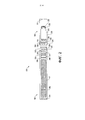
на Фиг. 1 показан вид сбоку устройства доставки аэрозоля, содержащего картридж, соединенный с управляющим корпусом, согласно одному примеру реализации настоящего изобретения;in FIG. 1 is a side view of an aerosol delivery device comprising a cartridge coupled to a control housing, according to one embodiment of the present invention;
на Фиг. 2 показан вид с частичным разрезом устройства доставки аэрозоля согласно различным примерам реализации;in FIG. 2 is a partial sectional view of an aerosol delivery device according to various embodiments;
На Фиг. 3 показаны различные элементы управляющего корпуса и картриджа устройства доставки аэрозоля согласно различным примерам реализации;FIG. 3 shows various elements of the control housing and cartridge of an aerosol delivery device according to various embodiments;
На Фиг. 4 показана перезаряжаемая литий-ионная батарея (LiB) согласно примерам реализации; иFIG. 4 shows a rechargeable lithium ion battery (LiB) according to exemplary embodiments; and
На Фиг. 5 показан источник питания для устройства доставки аэрозоля, который содержит перезаряжаемую литий-ионную батарею по Фиг. 4, согласно примерам реализации.FIG. 5 shows a power supply for an aerosol delivery device that contains the rechargeable lithium ion battery of FIG. 4, according to examples of implementation.
ОСУЩЕСТВЛЕНИЕ ИЗОБРЕТЕНИЯCARRYING OUT THE INVENTION
Настоящее изобретение описано более подробно ниже со ссылкой на его примеры реализации. Указанные примеры реализации описаны таким образом, что данное раскрытие основательно, полно и полностью передает объем изобретения для специалиста в данной области техники. В действительности, настоящее изобретение может быть реализовано во многих различных формах и не должно рассматриваться как ограниченное примерами реализации, приведенными в данном документе; скорее указанные примеры реализации приведены для того, чтобы данное изобретение соответствовало применимым законодательным требованиям. В данном описании и в прилагаемой формуле изобретения грамматическая конструкция, указывающая на то, что элемент приводится в единственном числе, также подразумевает и множественное число, если контекст изобретения явно не предписывает иное. Кроме того, в настоящем документе может сбыть приведена ссылка на количественные результаты измерения, значения, геометрические отношения или тому подобное, и если не указано иное, любой одно или более, если не все, из них, могут быть абсолютными или приблизительными, чтобы учесть допустимые примеры, которые могут иметь место, например, из-за технических допусков или тому подобного.The present invention is described in more detail below with reference to its examples of implementation. These examples of implementation are described in such a way that this disclosure thoroughly, completely and completely conveys the scope of the invention to a person skilled in the art. In fact, the present invention can be implemented in many different forms and should not be construed as limited to the examples of implementation given in this document; rather, these exemplary implementations are provided in order for the invention to comply with applicable legal requirements. In this description and in the appended claims, the grammatical construction indicating that an element is given in the singular also implies the plural, unless the context of the invention clearly dictates otherwise. In addition, reference may be made herein to quantitative measurement results, values, geometric relationships, or the like, and unless otherwise indicated, any one or more, if not all, of them may be absolute or approximate in order to account for acceptable examples that can occur, for example, due to technical tolerances or the like.
Как описано ниже, примеры реализации настоящего изобретения относятся к устройствам доставки аэрозоля. Устройства доставки аэрозоля согласно настоящему изобретению используют электрическую энергию для нагрева материала (предпочтительно без сжигания материала в какой-либо значительной степени) с образованием вдыхаемого вещества; и компоненты таких систем имеют форму изделий, наиболее предпочтительно, являющихся достаточно компактными для того чтобы считаться портативными устройствами. Другими словами, использование компонентов предпочтительных устройств доставки аэрозоля не приводит к образованию дыма в том смысле, что аэрозоль возникает из побочных продуктов сгорания или пиролиза табака, но скорее, использование указанных предпочтительных систем приводит к образованию паров, образующихся в процессе выпаривания или испарения определенных компонентов, включенных в них. В некоторых примерах реализации компоненты устройств доставки аэрозоля могут быть охарактеризованы как электронные сигареты, и указанные электронные сигареты наиболее предпочтительно включают табак и/или компоненты, полученные из табака, и затем доставляют компоненты, полученные из табака, в виде аэрозоля.As described below, exemplary embodiments of the present invention relate to aerosol delivery devices. Aerosol delivery devices according to the present invention use electrical energy to heat a material (preferably without burning the material to any significant extent) to form a respirable substance; and the components of such systems are in the form of articles, most preferably, being compact enough to be considered portable devices. In other words, the use of the components of the preferred aerosol delivery devices does not generate smoke in the sense that the aerosol arises from the by-products of combustion or pyrolysis of the tobacco, but rather the use of these preferred systems results in the generation of vapors generated during the evaporation or vaporization of certain components. included in them. In some embodiments, the components of aerosol delivery devices can be characterized as electronic cigarettes, and these electronic cigarettes most preferably include tobacco and / or components derived from tobacco, and then deliver the components derived from tobacco in the form of an aerosol.
Вырабатывающие аэрозоль средства определенных предпочтительных устройств доставки аэрозоля могут обеспечить множество ощущений (например, ритуалы затяжки и выпуска дыма, типы вкусов и ароматов, органолептические эффекты, физическое ощущение, ритуалы использования, визуальные сигналы, такие как те, которые обеспечены посредством видимого аэрозоля, и тому подобное) курения сигареты, сигары или трубки, которое обусловлено поджиганием и сжиганием табака (и затем вдыханием табачного дыма) без в какой-либо значительной степени сгорания каких-либо их компонентов. Например, пользователь вырабатывающего аэрозоль средства по настоящему изобретению может держать и использовать это средство подобно тому, как курильщик использует курительное изделие традиционного вида, осуществляя затяжку через один конец указанного средства для вдыхания аэрозоля, образованного этим средством, выполняя или осуществляя затяжки в выбранные промежутки времени и тому подобное.The aerosol producing means of certain preferred aerosol delivery devices can provide a variety of sensations (e.g., puff and smoke rituals, types of tastes and aromas, organoleptic effects, physical sensation, use rituals, visual cues such as those provided by visible aerosol, and the like) similar) smoking of a cigarette, cigar or pipe, which is caused by the ignition and combustion of tobacco (and then inhalation of tobacco smoke) without significantly combustion of any of their components. For example, a user of the aerosol-generating means of the present invention can hold and use the means in a manner similar to how a smoker uses a conventional-style smoking article, puffing through one end of said means for inhaling an aerosol generated by the means, performing or taking puffs at selected intervals, and the like.
Несмотря на то, что системы, описанные в настоящем документе в терминах примеров реализации, связанных с устройствами доставки аэрозоля, такими как так называемые «электронные сигареты», следует понимать, что механизмы, компоненты, признаки и способы могут быть реализованы во множестве различных форм и связаны со множеством различных изделий. Например, описание, представленное в настоящем документе, может быть реализовано в сочетании с примерами реализации курительных изделий традиционного вида (например, сигаретами, сигарами, трубками и т.д.), сигаретами с нагревом, но без горения, и связано с упаковкой любого продукта, описанного в настоящем документе. Соответственно следует понимать, что описание механизмов, компонентов, признаков и способов, раскрытых в настоящем документе, указано в терминах примеров реализации, относящихся к устройствам доставки аэрозоля исключительно для примера, и могут быть реализованы и использованы в различных других продуктах и способах.Although the systems described herein in terms of exemplary implementations associated with aerosol delivery devices such as so-called "electronic cigarettes", it should be understood that the mechanisms, components, features and methods can be implemented in many different forms and associated with many different products. For example, the description provided herein may be implemented in conjunction with examples of traditional smoking articles (e.g., cigarettes, cigars, pipes, etc.), heated cigarettes, but non-combustible, and associated with the packaging of any product. described in this document. Accordingly, it should be understood that the description of the mechanisms, components, features, and methods disclosed herein is in terms of exemplary implementations relating to aerosol delivery devices by way of example only, and may be implemented and used in various other products and methods.
Устройства доставки аэрозоля по настоящему изобретению также могут быть охарактеризованы как парообразующие изделия или изделия для доставки лекарственного препарата. Таким образом, такие изделия или устройства могут быть выполнены так, чтобы обеспечить одно или более веществ (например, ароматизаторов и/или фармацевтически активных ингредиентов) во вдыхаемой форме или вдыхаемом состоянии. Например, вдыхаемые вещества могут быть по существу в виде пара (например, вещество, которое находится в газообразной фазе при температуре ниже его критической точки). В качестве альтернативы вдыхаемые вещества могут быть в виде аэрозоля (например, суспензии из мелких твердых частиц или капель жидкости в газе). С целью упрощения подразумевается, что термин «аэрозоль», используемый в данном документе, включает в себя пары, газы и аэрозоли вида или типа, являющимися пригодными для вдыхания человеком, видимыми или невидимыми, а также такого вида, который может рассматриваться как дымообразный, или не такого вида.Aerosol delivery devices of the present invention can also be characterized as vaporous or drug delivery devices. Thus, such articles or devices can be designed to provide one or more substances (eg, fragrances and / or pharmaceutically active ingredients) in a respirable form or a respirable state. For example, respirable substances can be essentially in the form of vapor (for example, a substance that is in the gaseous phase at a temperature below its critical point). Alternatively, the respirable substances can be in the form of an aerosol (for example, a suspension of fine solid particles or liquid droplets in a gas). For purposes of simplicity, the term "aerosol" as used herein is intended to include vapors, gases, and aerosols of a species or type that is breathable, visible or invisible, as well as a species that may be considered smoke-like, or not that kind.
В процессе эксплуатации устройство доставки аэрозоля по настоящему изобретению может подвергаться множеству физических воздействий, применяемых индивидуумом при использовании курительного изделия традиционного вида (например, сигареты, сигары или трубки, которые используются при зажигании и вдыхании табака). Например, пользователь устройства доставки аэрозоля по настоящему изобретению может держать это изделие, как курительное изделие традиционного вида, осуществляя затяжку через один конец указанного изделия для вдыхания аэрозоля, образованного этим изделием, выполняя или осуществляя затяжки в выбранные промежутки времени и т.д.In use, the aerosol delivery device of the present invention can be subjected to a variety of physical effects that an individual uses when using a conventional type of smoking article (eg, a cigarette, cigar, or pipe used to light and inhale tobacco). For example, a user of the aerosol delivery device of the present invention can hold the article like a conventional smoking article, pulling through one end of the article to inhale the aerosol generated by the article, puffing or pulling at selected intervals, etc.
Устройства доставки аэрозоля по настоящему изобретению как правило содержат множество компонентов, обеспеченных внутри внешнего корпуса или оболочки, которые могут быть указаны как кожух. Общая конструкция внешнего корпуса или оболочки может варьироваться, и формат или конфигурация внешнего корпуса, которые могут определять общий размер и форму устройства доставки аэрозоля, могут варьироваться. Как правило, продолговатый корпус, напоминающий форму сигареты или сигары, может быть образован из одного единого кожуха или продолговатый кожух может быть образован из двух или более разъемных корпусов. Например, устройство доставки аэрозоля может содержать продолговатую оболочку или корпус, которые могут иметь по существу трубчатую форму и таким образом напоминать форму обычной сигареты или сигары. В одном примере все компоненты устройства доставки аэрозоля расположены в одном кожухе. В качестве альтернативы устройство доставки аэрозоля может содержать два или более кожухов, которые соединены и являются разъемными. Например, устройство доставки аэрозоля может иметь на одном конце управляющий корпус, содержащий кожух, содержащий один или более многоразовых компонентов (например, аккумулятор, например перезаряжаемый аккумулятор и/или суперконденсатор, и различное электронное оборудование для управления работой указанного изделия), а на другом конце присоединяемый к нему с возможностью съема внешний корпус или оболочку, содержащие одноразовую часть (например, одноразовый картридж, содержащий ароматизатор). Более конкретные форматы, конфигурации и расположения компонентов в одном типе кожуха блока или в многосоставном разъемном типе кожуха блока будут понятны на основании описания изобретения, приведенного ниже в настоящем документе. Кроме того, различные конструкции устройства доставки аэрозоля и размещения компонентов могут быть понятны при рассмотрении доступных на рынке электронных устройств доставки аэрозоля.Aerosol delivery devices of the present invention typically comprise a plurality of components provided within an outer housing or shell, which may be referred to as a housing. The overall design of the outer housing or shell can vary, and the format or configuration of the outer housing, which can determine the overall size and shape of the aerosol delivery device, can vary. Typically, the elongated body, resembling the shape of a cigarette or cigar, may be formed from one single case, or the elongated case may be formed from two or more split bodies. For example, the aerosol delivery device may comprise an elongated shell or body that may be substantially tubular and thus resemble the shape of a conventional cigarette or cigar. In one example, all components of the aerosol delivery device are located in a single housing. Alternatively, the aerosol delivery device may comprise two or more housings that are connected and detachable. For example, an aerosol delivery device may have at one end a control housing containing a housing containing one or more reusable components (for example, a battery, such as a rechargeable battery and / or supercapacitor, and various electronic equipment for controlling the operation of the specified product), and at the other end detachably attachable thereto an outer casing or shell containing a disposable portion (eg, a disposable cartridge containing a flavor). More specific formats, configurations and arrangement of components in one type of block casing or in a multi-piece split type of block casing will be understood based on the description of the invention set forth below in this document. In addition, the various aerosol delivery device designs and component placement can be understood by considering commercially available electronic aerosol delivery devices.
Устройства доставки аэрозоля по настоящему изобретению наиболее предпочтительно содержат некоторую комбинацию источника питания (например, источника электропитания), по меньшей мере одного управляющего компонента (например, средства для приведения в действие, управления, регулирования и прекращения подачи питания для вырабатывания тепла, например, посредством управления электрическим током от источника питания к другим компонентам изделия - например, микропроцессору, отдельному или как части микроконтроллера), нагревателя или вырабатывающего тепло элемента (например, нагревательный элемент с электрическим сопротивлением или другой компонент, который сам по себе или в комбинации с одним или более дополнительными элементами обычно может быть указан как «атомайзер»), композицию предшественника аэрозоля (например, обычно, жидкость, способную образовывать аэрозоль по приложении достаточного тепла, такие ингредиенты обычно указаны как «дымовой сок», «электронная жидкость» и «электронный сок»), и мундштучной области или кончика для обеспечения возможности осуществлять затяжку через устройство доставки аэрозоля для вдыхания аэрозоля (например, определенный путь потока воздуха через изделие, так что вырабатываемый аэрозоль может быть выведен из него после осуществления затяжки).Aerosol delivery devices of the present invention most preferably comprise some combination of a power source (e.g., a power source), at least one control component (e.g., means for actuating, controlling, regulating, and shutting off power to generate heat, e.g., by controlling electrical current from a power source to other components of the product - for example, a microprocessor, separate or as part of a microcontroller), a heater or heat-generating element (for example, an electrical resistance heating element or other component that, by itself or in combination with one or more additional elements can usually be referred to as "atomizer"), aerosol precursor composition (e.g., typically a liquid capable of forming an aerosol upon application of sufficient heat, such ingredients are commonly referred to as "smoke juice", "e-liquid" and "e-juice" ), and a mouthpiece or tip to allow puffing through the aerosol delivery device for inhaling the aerosol (e.g., a defined airflow path through the article so that the generated aerosol can be evacuated after puffing).
Выравнивание компонентов внутри устройства доставки аэрозоля по настоящему изобретению может варьироваться. В конкретных примерах реализации композиция предшественника аэрозоля может быть расположена рядом с концом устройства доставки аэрозоля, который может быть выполнен так, чтобы располагаться максимально близко ко рту пользователя так, чтобы максимизировать доставку аэрозоля пользователю. Однако не исключены и другие конструкции. В большинстве случаев нагревательный элемент может быть расположен достаточно близко к композиции предшественника аэрозоля так, чтобы тепло от нагревательного элемента могло испарить предшественник аэрозоля (так же как один или более ароматизаторов, медикаментов или тому подобного, которые могут быть аналогичным образом обеспечены для доставки пользователю) и образовать аэрозоль для доставки пользователю. Когда нагревательный элемент нагревает композицию предшественника аэрозоля, образуется аэрозоль, высвобожденный или сгенерированный в физическую форму, подходящую для вдыхания потребителем. Следует понимать, что вышеприведенные термины являются взаимозаменяемыми таким образом, что ссылка на любую форму термина «высвобождение» включает любую форму термина «формирование» или «генерация». В частности, вдыхаемое вещество высвобождается в виде пара или аэрозоля или их смеси, причем такие термины также являются взаимозаменяемыми в настоящем документе, если не указано обратное.The alignment of the components within the aerosol delivery device of the present invention can vary. In specific embodiments, the aerosol precursor composition may be located near the end of the aerosol delivery device, which may be configured to be as close as possible to the user's mouth so as to maximize delivery of the aerosol to the user. However, other designs are not excluded. In most cases, the heating element may be positioned close enough to the aerosol precursor composition so that heat from the heating element can vaporize the aerosol precursor (as well as one or more flavorings, medicaments, or the like that may similarly be provided for delivery to the user) and form an aerosol for delivery to a user. When the heating element heats the aerosol precursor composition, an aerosol is generated, released or generated into a physical form suitable for inhalation by the consumer. It should be understood that the above terms are interchangeable such that reference to any form of the term "release" includes any form of the term "formation" or "generation". In particular, the respirable substance is released in the form of vapor or aerosol, or mixtures thereof, and such terms are also used interchangeably herein, unless otherwise indicated.
Как отмечено выше, устройство доставки аэрозоля может содержать аккумулятор или другой электрический источник питания для обеспечения потока тока, достаточного для обеспечения различных функций устройства доставки аэрозоля, таких как питание нагревателя, питание систем управления, питание индикаторов и тому подобное. Источник питания может быть выполнен в виде различных примеров реализации. Предпочтительно источник питания способен доставлять достаточное количество энергии для быстрого нагрева нагревательного элемента для обеспечения образования аэрозоля и питания устройства доставки аэрозоля в процессе эксплуатации в течение требуемого периода времени. Источник питания предпочтительно имеет такой размер чтобы его было удобно разместить внутри устройства доставки аэрозоля так, чтобы с устройством доставки аэрозоля можно было легко обращаться. Также предпочтительный источник питания имеет достаточно небольшой вес, чтобы не ухудшать желаемый пользовательский опыт от курения.As noted above, the aerosol delivery device may include a battery or other electrical power source to provide sufficient current to provide various functions of the aerosol delivery device, such as powering a heater, powering control systems, powering indicators, and the like. The power supply can be made in the form of various examples of implementation. Preferably, the power supply is capable of delivering sufficient energy to rapidly heat the heating element to generate aerosol and power the aerosol delivery device in service for a desired period of time. The power supply is preferably sized to fit comfortably within the aerosol delivery device so that the aerosol delivery device can be easily handled. Also, the preferred power source is light enough not to impair the desired smoking user experience.
Более конкретные форматы, конфигурации и расположения компонентов в устройствах доставки аэрозоля по настоящему изобретению будут понятны на основании описания изобретения, приведенного ниже в настоящем документе. Кроме того, выбор и расположение различных компонентов устройства доставки аэрозоля могут быть оценены при рассмотрении имеющихся в продаже электронных устройств доставки аэрозоля. Также информация относительно форматов, конфигураций и расположения компонентов в устройствах доставки аэрозоля по настоящему изобретению, так же как и имеющиеся в продаже электронные устройства доставки аэрозоля, может быть найдена в заявке на патент США №15/291,771 под авторством Sur и др., с датой подачи 12 октября 2016, которая включена в настоящий документ посредством ссылки.More specific formats, configurations and arrangements of components in aerosol delivery devices of the present invention will be understood based on the description of the invention set forth herein below. In addition, the selection and arrangement of the various components of the aerosol delivery device can be evaluated by considering commercially available electronic aerosol delivery devices. Also, information regarding the formats, configurations and arrangement of components in aerosol delivery devices of the present invention, as well as commercially available electronic aerosol delivery devices, can be found in US Patent Application No. 15 / 291,771 by Sur et al., Dated filing October 12, 2016, which is incorporated herein by reference.
На Фиг. 1 показан вид сбоку устройства 100 доставки аэрозоля, содержащего управляющий корпус 102 и картридж 104 согласно различным примерами реализации настоящего изобретения. В частности, на Фиг. 1 показан управляющий корпус и картридж, соединенные друг с другом. Управляющий корпус и картридж могут быть разъемно выровнены в функциональном отношении. Различные механизмы могут соединять картридж и управляющий корпус, например, в виде резьбового сцепления, сцепления с плотной посадкой, посадки с натягом, магнитного сцепления и тому подобного. В некоторых примерах реализации устройство доставки аэрозоля может быть по существу стержнеобразным, по существу трубчатой формы или по существу цилиндрической формы, когда картридж и управляющий корпус находятся в собранной конфигурации. Устройство доставки аэрозоля может быть также по существу прямоугольным, ромбовидным или треугольным в поперечном сечении, многогранной формы, или тому подобным, некоторые из которых могут придавать ему большую совместимость с по существу плоским или тонкослойным источником электроэнергии, таким как источник электроэнергии, содержащий плоскую батарею.FIG. 1 shows a side view of an
Картридж и управляющий корпус могут содержать соответствующие отдельные кожухи или внешние корпусы, которые могут быть образованы из любого количества различных материалов. Кожух может быть образован из любого подходящего конструктивно прочного материала. В некоторых примерах кожух может быть образован из металла или сплава, таких как нержавеющая сталь, алюминий или тому подобное. Другие подходящие материалы включают различные виды пластмасс (например, поликарбонат), пластмассы с металлическим напылением, керамику и тому подобное.The cartridge and control housing can comprise respective separate housings or outer housings, which can be formed from any number of different materials. The shroud can be formed from any suitable structurally strong material. In some examples, the casing may be formed from a metal or alloy such as stainless steel, aluminum, or the like. Other suitable materials include various types of plastics (eg, polycarbonate), metal spray plastics, ceramics, and the like.
В некоторых примерах реализации управляющий корпус 102 и/или картридж 104 устройства 100 доставки аэрозоля могут быть одноразовыми или многоразовыми. Например, управляющий корпус может иметь сменный аккумулятор или перезаряжаемый аккумулятор и таким образом может быть скомбинирован с любым типом технологии перезарядки, включая подключение к обычной настенной электрической розетке, подключение к автомобильному зарядному устройству (например, гнезду прикуривателя), подключение к компьютеру, например, через кабель или разъем универсальной последовательной шины (USB), подключение к фотоэлектрическому элементу (иногда указан как солнечный фотоэлемент), к фотоэлектрической панели солнечных фотоэлементов или подключение к преобразователю радиочастоты в постоянный ток. Также в некоторых примерах реализации картридж может представлять собой картридж одноразового использования, как описано в патенте США №8,910,639 под авторством Chang и др., который включен в настоящий документ посредством ссылки.In some embodiments, the
На Фиг. 2 более подробно показано устройство 100 доставки аэрозоля в соответствии с некоторыми примерами реализации. Как видно на виде с частичным разрезом, устройство доставки аэрозоля может содержать управляющий корпус 102 и картридж 104, каждый из которых содержит множество соответствующих компонентов. Компоненты, показанные на Фиг. 2, представляют собой характерные компоненты, которые могут присутствовать в управляющем корпусе и картридже и не предназначены для ограничения объема компонентов, которые охвачены настоящим раскрытием. Как показано, например, управляющий корпус может быть образован оболочкой 206 управляющего корпуса, которая может включать компонент 208 управления (например, микропроцессор, сам по себе являющийся микроконтроллером или представляющий его часть), датчик 210 потока, источник 212 питания и один или более светоизлучающих диодов 214, с вето излучающие диоды с использованием квантовых точек или тому подобное, и такие компоненты могут быть выборочно выравнены. Источник питания может содержать, например, батарею (одноразовую или перезаряжаемую), перезаряжаемый суперконденсатор, перезаряжаемую твердотельную батарею, перезаряжаемую литий-ионную батарею или тому подобное, или некоторую их комбинацию. Некоторые примеры подходящих источников питания описаны в заявке на патент США №14/918,926 под авторством Sur и др., с датой подачи 21 октября 2015, которая включена в настоящий документ посредством ссылки. Светоизлучающий диод может быть одним из примеров подходящего визуального индикатора, которым может быть оснащено устройство доставки аэрозоля. Другие индикаторы, такие как звуковые индикаторы (например, динамики) тактильные индикаторы (например, вибрационные двигатели) или тому подобное, могут содержаться в дополнение к или как альтернатива визуальным индикаторам, таким как светоизлучающий диод, светодиоды с поддержкой квантовых точек.FIG. 2, an
Картридж 104 может быть образован оболочкой 216 картриджа, в котором заключен резервуар 218, выполненную с возможностью удержания композиции предшественника аэрозоля, и содержащей нагреватель 222 (иногда называемый нагревательным элементом). В различных конфигурациях указанная конструкция может быть названа как камера; и соответственно термины «картридж», «камера» и тому подобные могут быть использованы как взаимозаменяемые для обозначения оболочки или другого кожуха, в котором заключен резервуар для композиции предшественника аэрозоля и содержащего нагреватель.The
Как показано в некоторых примерах, резервуар 218 может сообщаться по текучей среде с элементом 220 для переноса жидкости, выполненным с возможностью впитывания или переноса иным способом композиции предшественника аэрозоля, хранящейся в резервуаре кожуха, к нагревателю 222. В некоторых примерах клапан может быть расположен между резервуаром и нагревателем и выполнен с возможностью управления количеством композиции предшественника аэрозоля, пропущенным или доставленным из резервуара к нагревателю.As shown in some examples,
Различные примеры материалов, выполненных с возможностью выработки тепла, когда к ним подается электрический ток, могут быть использованы для формирования нагревателя 222. Нагреватель в указанных примерах может быть резистивным нагревающим элементом, таким как проволочная спираль, микронагреватель и тому подобное. Примеры материалов, из которых может быть выполнен нагревательный элемент, включают фехраль (FeCrAl), нихром, нержавеющую сталь, дисилицид молибдена (MoSi2), силицид молибдена (MoSi), дисилицид молибдена легированный алюминием (Mo(Si,Al)2), графит и материалы на основе графита (например, пеноматериалы и нити на основе углерода) и керамику (например, керамику с положительным или отрицательным температурным коэффициентом). Примеры реализации нагревателей или нагревательных элементов, используемых в устройствах доставки аэрозоля в соответствии с настоящим изобретением, дополнительно описаны ниже и могут быть включены в устройства так, как описано в данном документе.Various examples of materials capable of generating heat when an electric current is applied to them may be used to form
Отверстие 224 может находиться в оболочке 216 картриджа (например, на кончике мундштука) чтобы обеспечить выход образованного аэрозоля из картриджа 104.
Картридж 104 также может содержать один или более электронных компонентов 226, которые могут содержать интегральную схему, компонент памяти (например, электронно-стираемое программируемое постоянное запоминающее устройство (EEPROM), флэш-память), датчик или тому подобное. Электронные компоненты могут быть выполнены с возможностью сообщения с компонентом 208 управления и/или с внешним устройством посредством проводных или беспроводных средств. Электронные компоненты могут быть расположены в любом месте в картридже или его основании 228.
Хотя компонент 208 управления и датчик 210 потока показаны отдельно, следует понимать, что различные электронные компоненты, включая компонент управления и датчик потока, могут быть скомбинированы на электронной печатной монтажной плате, которая поддерживает и электрически соединяет электронные компоненты. Также печатная монтажная плата может быть расположена горизонтально относительно иллюстрации по Фиг. 1, на которой печатная монтажная плата может быть продольно параллельна центральной оси управляющего корпуса. В некоторых примерах датчик потока воздуха может содержать свою собственную печатную монтажную плату или другой основной элемент, к которому он может быть прикреплен. В некоторых примерах может быть использована гибкая печатная монтажная плата. Гибкая печатная монтажная плата может быть выполнена в различных формах, включая по существу трубчатые формы. В некоторых примерах гибкая печатная монтажная плата может быть скомбинирована с подложкой нагревателя, наложена на нее в виде слоя или может образовывать часть или всю подложку нагревателя.Although
Управляющий корпус 102 и картридж 104 могут содержать компоненты, выполненные с возможностью способствования взаимодействию по текучей среде друг с другом. Как показано на Фиг. 2, управляющий корпус может содержать соединитель 230, имеющий полость 232. Основание 228 картриджа может быть выполнено с возможностью сцепления с соединителем и может содержать выступ 234, выполненный с возможностью установки в полости. Такое взаимодействие может способствовать стабильному соединению между управляющим корпусом и картриджем, а также устанавливать электрическое соединение между источником 212 питания и компонентом 208 управления в управляющем корпусе и нагревателе 222 в картридже. Также оболочка 206 управляющего корпуса может содержать воздухозаборник 236, который может представлять собой выемку в оболочке, в которой он соединен с соединителем, что обеспечивает прохождение воздуха из окружающей среды вокруг соединителя в оболочку, где он затем проходит через полость 232 соединителя в картридж через выступ 234.The
Соединитель и основание, используемые в соответствии с настоящим изобретением, описаны в публикации заявки на патент США №2014/0261495 под авторством Novak и др., которая включена в настоящий документ посредством ссылки. Например, соединитель 230, показанный на Фиг. 2, может образовывать внешнюю периферию 238, выполненную с возможностью сопряжения с внутренней периферией 240 основания 228. В одном примере внутренняя периферия основания может определять радиус, который по существу равен или немного больше радиуса внешней периферии соединителя. Также соединитель может образовывать один или более выступов 242 на внешней периферии, выполненных с возможностью взаимодействия с одним или более углублениями 244, образованными на внутренней периферии основания. Однако для соединения основания с соединителем могут быть использованы различные другие примеры конструкций, форм и компонентов. В некоторых примерах соединение между основанием картриджа 104 и соединителем управляющего корпуса 102 может быть по существу постоянным, тогда как в других примерах указанное соединение между ними может быть разъемным, так что, например, управляющий корпус может быть повторно использован с одним или более дополнительными картриджами, которые могут быть одноразовыми и/или многоразовыми.The connector and base used in accordance with the present invention are described in US Patent Application Publication No. 2014/0261495 by Novak et al., Which is incorporated herein by reference. For example, the
Резервуар 218, показанный на Фиг. 2, может представлять собой контейнер или волокнистый резервуар, как описано в настоящем документе. Например, в данном примере резервуар может содержать один или более слоев нетканого волокна и может быть по существу образована в виде трубки, охватывающей внутреннюю часть оболочки 216 картриджа. Композиция предшественника аэрозоля может удерживаться в резервуаре. Жидкие компоненты, например, могут удерживаться в резервуаре сорбционно. Резервуар может быть соединен по текучей среде с элементом 220 для переноса жидкости. В указанном примере элемент для переноса жидкости может переносить композицию предшественника аэрозоля, хранимую в резервуаре, посредством капиллярного действия к нагревателю 222, который представляет собой спираль металлической проволоки. Как правило, нагреватель расположен в устройстве для нагрева с элементом для переноса жидкости. Примеры реализации резервуаров и элементов для переноса, используемых в устройствах доставки аэрозоля в соответствии с настоящим изобретением, дополнительно описаны ниже, и такие резервуары и/или элементы для переноса могут быть включены в устройства так, как описано в данном документе. В частности, конкретные комбинации нагревательных элементов и элементов для переноса, которые описаны ниже в данном документе, могут быть включены в устройства так, как описано в данном документе.The
В процессе эксплуатации, когда пользователь осуществляет затяжку через устройство 100 доставки аэрозоля, поток воздуха определяют посредством датчика 210 потока, а нагреватель 222 приводят в действие для испарения компонентов композиции предшественника аэрозоля. Осуществление затяжки через мундштук устройства доставки аэрозоля вызывает вход воздуха из окружающей среды в воздухозаборник 236 и его проход через полость 232 в соединителе 230 и центральное отверстие выступа 234 основания 228. В картридже 104 втянутый воздух объединяется с образованным паром с образованием аэрозоля. Аэрозоль удаляется при высасывании, вытягивании или при осуществлении затяжки иным способом из нагревателя и выходит из отверстия 224 в мундштуке устройства доставки аэрозоля.In use, when the user puffs through the
В некоторых примерах устройство 100 доставки аэрозоля может содержать множество дополнительных программно-управляемых функций. Например, устройство доставки аэрозоля может содержать схему защиты источника питания, выполненную с возможностью обнаружения входа источника питания, нагрузки на клеммы источника питания и входа зарядки. Схема защиты источника питания может содержать защиту от короткого замыкания, блокировку под напряжением и/или защиту от перегрузки напряжения, температурную компенсацию аккумулятора. Устройство доставки аэрозоля также может содержать компоненты для измерения температуры окружающей среды, а его компонент 208 управления может быть выполнен с возможностью управления по меньшей мере одним функциональным элементом для предотвращения зарядки источника питания, в частности любой батареи, если температура окружающей среды ниже определенной температуры (например, 0°С) или выше определенной температуры (например, 45°С) перед началом зарядки или во время зарядки.In some examples,
Подача электроэнергии из источника 212 питания может изменяться в течение каждой затяжки на устройстве 100 в соответствии с механизмом управления электроэнергией. Устройство может содержать таймер безопасности «долгой затяжки», так что в случае, если пользователь или неисправность компонента (например, датчика 210 потока) заставит устройство попытаться выполнить непрерывную затяжку, компонент 208 управления может управлять по меньшей мере одним функциональным элементом для автоматического прекращения затяжки после некоторого периода времени (например, четырех секунд). Также время между затяжками на устройстве может быть ограничено меньше, чем заданный период времени (например, 100 секунд). Контрольный таймер безопасности может автоматически перезагружать устройство доставки аэрозоля, если его компонент управления или программное обеспечение, работающее на нем, становится нестабильным и не обслуживает таймер в течение соответствующего интервала времени (например, восьми секунд). Дополнительная безопасность может быть обеспечена в случае неисправного или иным способом не действующего датчика 210 потока, например, посредством постоянного отключения устройства доставки аэрозоля для предотвращения непреднамеренного нагрева. Ограничивающий затягивание выключатель может деактивировать устройство в случае ошибки датчика давления, в результате которой устройство будет непрерывно работать без остановки после четырех секунд максимального времени затяжки.The power supply from the
Устройство 100 доставки аэрозоля может содержать алгоритм отслеживания затяжки, выполненный с возможностью отключения нагревателя, как только будет достигнуто определенное количество затяжек для присоединенного картриджа (основано на количестве доступных затяжек, рассчитанном с учетом заряда электронной жидкости в картридже). Устройство доставки аэрозоля может включать в себя функцию спящего режима, режима ожидания или режима пониженного энергопотребления, при котором подача электроэнергии может быть автоматически отключена после определенного периода неиспользования. Дополнительная безопасность может быть обеспечена тем, что все циклы зарядки/разрядки источника 212 питания могут отслеживаться посредством компонента 208 управления в течение его срока службы. После того как источник питания достиг эквивалентного заранее определенного количества (например, 200) циклов полной разрядки или полной зарядки, он может быть объявлен истощенным, а компонент управления может управлять по меньшей мере одним функциональным элементом для предотвращения дальнейшей зарядки источника питания.
Различные компоненты устройства доставки аэрозоля согласно настоящему изобретению могут быть выбраны из компонентов, описанных в уровне техники и имеющихся на рынке. Примеры аккумуляторов, которые могут быть использованы согласно настоящему изобретению, описаны в патенте США №9,484,155 под авторством Peckerar и др., который включен в настоящий документ посредством ссылки.The various components of the aerosol delivery device of the present invention may be selected from those described in the prior art and commercially available. Examples of batteries that can be used in accordance with the present invention are described in US Pat. No. 9,484,155 by Peckerar et al., Which is incorporated herein by reference.
Устройство 100 доставки аэрозоля может также содержать датчик 210 или другой датчик, или чувствительный элемент для управления подачей электрической электроэнергии к нагревателю 222, когда требуется выработка аэрозоля (например, во время затяжки в процессе эксплуатации). Таким образом, например, обеспечен метод или способ отключения электроэнергии нагревателя, когда устройство доставки аэрозоля не задействовано в процессе эксплуатации, и для включения электроэнергии для приведения в действие или запуска выработки тепла посредством нагревателя во время затяжки. Дополнительные характерные типы механизмов восприятия или определения, их структура и конфигурация, их компоненты и общие способы их работы описаны в патенте США №5,261,424 под авторством Sprinkel, Jr., в патенте США №5,372,148 под авторством McCafferty и др., и в публикации патентной заявки РСТ № WO 2010/003480 под авторством Flick, все из которых включены в настоящий документ посредством ссылки.
Устройство 100 доставки аэрозоля наиболее предпочтительно содержит компонент 208 управления или другой механизм управления для управления количеством электрической энергии, подаваемой к нагревателю 222 во время затяжки. Характерные типы электронных компонентов, их структура и конфигурация, их особенности и общие способы их работы описаны в патенте США №4,735,217 под авторством Gerth и др., в патенте США №4,947,874 под авторством Brooks и др., в патенте США №5,372,148 под авторством McCafferty и др., в патенте США №6,040,560 под авторством Fleischhauer и др., в патенте США №7,040,314 под авторством Nguyen и др., в патенте США №8,205,622 под авторством Pan, в публикации заявки на патент США №8,881,737 под авторством Collet и др., в патенте США №9,423,152 под авторством Ampolini и др., в патенте США №9,439,454 под авторством Fernando и др., и в публикации заявки на патент США №2015/0257445 под авторством Henry и др., все из которых включены в настоящий документ посредством ссылки.
Характерные типы подложек, резервуаров или других компонентов для поддержки предшественника аэрозоля описаны в патенте США №8,528,569 под авторством Newton, в публикации заявки на патент США №2014/0261487 под авторством Chapman и др., в публикации заявки на патент США №2015/0059780 под авторством Davis и др., и в публикации заявки на патент США №2015/0216232 под авторством Bless и др., все из которых включены в настоящий документ посредством ссылки. Также различные впитывающие материалы, а также конфигурация и работа данных впитывающих материалов в определенных типах электронных сигарет приведены в патенте США №8,910,640 под авторством Sears и др., которая включена в настоящий документ посредством ссылки.Representative types of substrates, reservoirs, or other components to support the aerosol precursor are described in U.S. Patent No. 8,528,569 to Newton, in U.S. Patent Application Publication No. 2014/0261487 to Chapman et al., In U.S. Patent Application Publication No. 2015/0059780 under by Davis et al. and US Patent Application Publication No. 2015/0216232 by Bless et al., all of which are incorporated herein by reference. Also, various absorbent materials, as well as the configuration and operation of these absorbent materials in certain types of electronic cigarettes, are described in US Pat. No. 8,910,640 to Sears et al., Which is incorporated herein by reference.
Композиция предшественника аэрозоля, также называемая композицией предшественника пара, может содержать различные компоненты, включая, к примеру, многоатомный спирт (например, глицерин, пропиленгликоль или их смесь), никотин, табак, экстракт табака и/или ароматизаторы. Типичные типы компонентов и составов предшественника аэрозоля также известны и охарактеризованы в патенте США №7,217,320 под авторством Robinson и др., в патенте США №9,254,002 под авторством Chong и др.; в патенте США №8,881,737 под авторством Collett и др.; в публикации заявки на патент США №2013/0008457 под авторством Zheng и др.; в публикации заявки на патент США №2015/0020823 под авторством Lipowicz и др.; и в публикации заявки на патент США №2015/0020830 под авторством Koller, а также в публикации РСТ заявки на патент США WO №2014/182736 под авторством Bowen и др., и в заявке на патент США №15/222,615 под авторством Watson и др., с датой подачи 28 июля 2016, раскрытия которых включены в настоящий документ посредством ссылки. Другие предшественники аэрозоля, которые могут быть использованы, включают предшественники аэрозоля, которые включены в продукт VUSE® компании R. J. Reynolds Vapor Company, в продукт BLU™ компании Imperial Tobacco Group PLC, в продукт MISTIC MENTHOL компании Mistic Ecigs и в продукт VYPE компании CN Creative Ltd. Также предпочтительны так называемые «дымовые соки» для электронных сигарет, которые доступны от компании Джонсон Крик Интерпрайз ЛЛС.The aerosol precursor composition, also called the vapor precursor composition, can contain various components including, for example, a polyhydric alcohol (eg, glycerin, propylene glycol, or a mixture thereof), nicotine, tobacco, tobacco extract, and / or flavors. Typical types of aerosol precursor components and formulations are also known and described in US Pat. No. 7,217,320 to Robinson et al., In US Pat. No. 9,254,002 to Chong et al .; US Pat. No. 8,881,737 by Collett et al .; US Patent Application Publication No. 2013/0008457 by Zheng et al; US Patent Application Publication No. 2015/0020823 by Lipowicz et al; and in US Patent Application Publication No. 2015/0020830 by Koller, as well as in PCT Publication of US Patent Application WO No. 2014/182736 by Bowen et al., and in US Patent Application No. 15 / 222,615 by Watson and others, filing July 28, 2016, the disclosures of which are incorporated herein by reference. Other aerosol precursors that can be used include aerosol precursors, which are included in RJ Reynolds Vapor Company VUSE®, Imperial Tobacco Group PLC's BLU ™ product, Mistic Ecigs' MISTIC MENTHOL product, and CN Creative Ltd's VYPE product. ... Also preferred are so-called "smoke juices" for electronic cigarettes, which are available from Johnson Creek Enterprises LLC.
Примеры реализации шипучих материалов могут быть использованы в предшественнике аэрозоля и описаны, на примере публикации заявки на патент США №2012/0055494 под авторством Hunt и др., которая включена в настоящий документ посредством ссылки. Также использование шипучих материалов описано, например, в патенте США №4,639,368 под авторством Niazi и др., в патенте США №5,178,878 под авторством Wehling и др., в патенте США №5,223,264 под авторством Wehling и др., в патенте США №6,974,590 под авторством Pather и др., в патенте США №7,381,667 под авторством Bergquist и др., в патенте США №8,424,541 под авторством Crawford и др., и в патенте США №8,627,828 под авторством Strickland и др., а также в патенте США №9,307,787 под авторством Sun и др., в публикации заявки на патент США №2010/0018539 под авторством Brinkley и др., и в публикации РСТ заявки на патент США WO №97/06786 под авторством Sun и др.; и в РСТ WO 97/06786 под авторством Johnson и др., все из которых включены в настоящий документ посредством ссылки. Также описание в отношении примеров реализации композиций предшественника аэрозоля, включая описание табака или компонентов, полученных из включенного в нее табака, обеспечено в заявках на патент США №15/216,582 и 15/216,590, каждая с датой подачи 21 июля 2016 и каждая под авторством Davis и др., которые включены в настоящий документ посредством ссылки.Examples of embodiments of effervescent materials can be used in an aerosol precursor and are described in US Patent Application Publication No. 2012/0055494 by Hunt et al., Which is incorporated herein by reference. Also, the use of effervescent materials is described, for example, in US patent No. 4,639,368 by Niazi et al., In US patent No. 5,178,878 by Wehling et al., In US patent No. 5,223,264 by Wehling et al., In US patent No. 6,974,590 under by Pather et al., US Pat. No. 7,381,667 by Bergquist et al., US Pat. No. 8,424,541 by Crawford et al., and US Pat. No. 8,627,828 by Strickland et al., and US Pat. No. 9,307,787 by Sun et al., in US Patent Application Publication No. 2010/0018539 by Brinkley et al., and PCT Publication of US Patent Application No. WO No. 97/06786 by Sun et al .; and PCT WO 97/06786 by Johnson et al., all of which are incorporated herein by reference. Also, description with respect to exemplary embodiments of aerosol precursor compositions, including descriptions of tobacco or components derived from the included tobacco, is provided in U.S. Patent Application Nos. 15 / 216,582 and 15 / 216,590, each filing Jul 21, 2016 and each by Davis and others, which are incorporated herein by reference.
Характерные типичные типы компонентов, которые подают визуальные сигналы или индикаторы, могут быть использованы в устройстве 100 доставки аэрозоля, такие как визуальные индикаторы и связанные компоненты, слуховые индикаторы, тактильные индикаторы и тому подобное. Примеры подходящих компонентов светоизлучающих диодов, а также их конфигурации и использование описаны в патенте США №5,154,192 под авторством Sprinkel и др., в патенте США №8,499,766 под авторством Newton, в патенте США №8,539,959 под авторством Scatterday, и в патенте США №9,451,791 под авторством Sears и др., все из которых включены в настоящий документ посредством ссылки.Representative typical types of components that provide visual signals or indicators can be used in
Другие признаки, средства управления или компоненты, которые могут содержаться в устройствах доставки аэрозоля по настоящему изобретению, описаны в патенте США №5,967,148 под авторством Harris и др., в патенте США №. 5,934,289 под авторством Watkins и др., в патенте США №5,954,979 под авторством Counts и др., в патенте США №6,040,560 под авторством Fleischhauer и др., в патенте США №8,365,742 под авторством Hon, в патенте США №8,402,976 под авторством Fernando и др., в публикации заявки на патент США №2005/0016550 под авторством Katase, в патенте США №8,689,804 под авторством Fernando и др., в публикации заявки на патент США №2013/0192623 под авторством Tucker и др., в патенте США №9,427,022 под авторством Leven и др., в публикации заявки на патент США №2013/0180553 под авторством Kim и др., в публикации заявки на патент США №2014/0000638 под авторством Sebastian и др., в публикации заявки на патент США №2014/0261495 под авторством Novak и др., и в патенте США №9,220,302 под авторством DePiano и др., все из которых включены в настоящий документ посредством ссылки.Other features, controls, or components that may be contained in aerosol delivery devices of the present invention are described in US Pat. No. 5,967,148 to Harris et al. US Pat. No. 5,967,148. 5,934,289 by Watkins et al., US Pat. No. 5,954,979 by Counts et al., In US Pat. No. 6,040,560 by Fleischhauer et al., In US Pat. No. 8,365,742 by Hon, in US Pat. No. 8,402,976 by Fernando and et al., in US Patent Application Publication No. 2005/0016550 by Katase, in US Patent No. 8,689,804 by Fernando et al., in US Patent Application Publication No. 2013/0192623 by Tucker et al., in US Patent No. 9,427,022 by Leven et al., In US Patent Application Publication No. 2013/0180553 by Kim et al., In US Patent Application Publication No. 2014/0000638 by Sebastian et al., In US Patent Application Publication No. 2014 / 0261495 by Novak et al. And US Pat. No. 9,220,302 by DePiano et al., All of which are incorporated herein by reference.
Как указано выше, компонент 208 управления содержит множество электронных компонентов и, в некоторых примерах реализации, может быть образован на печатной монтажной плате (РСВ). Электронные компоненты могут содержать микропроцессор или ядро процессора и память. В некоторых примерах компонент управления может содержать микроконтроллер с интегрированным ядром процессора и памятью, и может дополнительно содержать одно или более интегрированных внешних устройств ввода/вывода. В некоторых примерах компонент управления может быть связан с интерфейсом 246 связи для обеспечения беспроводного соединения с одной или более сетями, вычислительными устройствами или другими устройствами на подходящей основе. Примеры подходящих интерфейсов связи раскрыты в публикации заявки на патент США №2016/0261020 под авторством Marion и др., содержание которой включено в настоящий документ посредством ссылки. Другой пример подходящего интерфейса связи представляет собой одночиповый беспроводной микроконтроллер (MCU) СС3200 от Texas Instruments. Также примеры подходящих методов, согласно которым устройство доставки аэрозоля может быть выполнено с возможностью беспроводной связи, раскрыты в публикации заявки на патент США №2016/0007651, под авторством Ampolini и др., и в публикации заявки на патент США №2016/0219933, под авторством Henry, Jr. и др., каждая из которых включена в настоящий документ посредством ссылки.As noted above, the
В соответствии с некоторыми примерами реализации компонент 208 управления может содержать или может быть соединен с датчиком 248 движения, выполненным с возможностью обнаружения определенного движения устройства 100 доставки аэрозоля, которое указывает на уязвимость устройства доставки аэрозоля. Датчик движения может представлять собой любое множество датчиков, которые могут быть выполнены с возможностью обнаружения определенного движения, преобразования определенного движения в электрический сигнал и вывода электрического сигнала. Примеры подходящих датчиков движения включают один датчик наклона или комбинацию датчиков наклона, одно- или многоосные акселерометры, гироскопы и тому подобное, любой один или более из которых могут быть сконструированы с использованием технических средств на основе микроэлектромеханических систем (МЭМС).In accordance with some example implementations, the
Датчик 248 движения может быть выполнен с возможностью преобразования определенного движения в электрический сигнал. Компонент 208 управления или датчик движения может быть выполнен с возможностью распознавания уязвимости и операции, связанной с уязвимостью, на основе электрического сигнала. В некоторых примерах определенное движение, обнаруживаемое посредством датчика движения, может включать в себя вибрацию, толчок или свободное падение. Рассмотрим, в частности, примеры, в которых датчик движения представляет собой акселерометр. В указанных примерах вибрация может быть обнаружена посредством периодического ускорения по меньшей мере пороговой величины. В дополнение или в качестве альтернативы толчок может быть обнаружен посредством по меньшей мере пороговой величины ускорения в течение периода времени меньшего, чем пороговый период времени, или свободное падение может быть обнаружено посредством величины ускорения меньшей, чем пороговая величина ускорения, в течение по меньшей мере порогового периода времени.The
Компонент управления затем может быть выполнен с возможностью управления по меньшей мере одним функциональным элементом устройства 100 доставки аэрозоля для выполнения указанной операции, которая может быть выполнена им при обнаружении уязвимости. Например, компонент управления может быть выполнен с возможностью отключения источника 212 питания, который может быть отключен им при обнаружении уязвимости устройства доставки аэрозоля. Для большей информации относительно данного аспекта см. заявку на патент США №14/961,421 под авторством Sur и др., поданную 7 декабря 2015, которая включена в настоящий документ посредством ссылки.The control component can then be configured to control at least one functional element of the
В соответствии с некоторыми примерами реализации компонент 208 управления может быть выполнен с возможностью управления одним или более функциональными элементами устройства 100 доставки аэрозоля в различных состояниях устройства. На Фиг. 3 показан управляющий корпус 102, соединенный с картриджем 104 в активном режиме. Как показано, управляющий корпус может содержать положительные и отрицательные клеммы 302, 304, выполненные с возможностью соединения с соответствующими клеммами нагревателя 222 (нагревательного элемента). Компонент 208 управления может содержать микропроцессор 306 и множество других электрических компонентов, таких как резисторы, конденсаторы, выключатели и тому подобное, которые могут быть соединены с источником 212 питания и нагревателем с образованием электрической схемы. В некоторых примерах нагреватель может содержать клемму связи для передачи данных, таких как подсчет затяжек.In accordance with some example implementations, the
В соответствии с примерами реализации настоящего изобретения микропроцессор 306 может быть выполнен с возможностью измерения напряжения на положительной клемме 302 и управления энергией, подаваемой на нагреватель 222, на его основе. В некоторых примерах микропроцессор может также управлять работой по меньшей мере одного функционального элемента устройства 100 доставки аэрозоля на основании напряжения на положительной клемме. Одним примером подходящего функционального элемента может быть индикатор 308, такой как визуальный, звуковой или тактильный индикатор.In accordance with exemplary embodiments of the present invention, the
Микропроцессор 306 может работать от действительного напряжения на положительной клемме 302 или может содержать аналого-цифровой преобразователь (АЦП) для преобразования действительного напряжения в цифровой эквивалент. В некоторых примерах аналого-цифровой преобразователь может быть рассчитан на максимальное напряжение, меньшее, чем максимум, который может присутствовать на положительной клемме. В указанных примерах компонент 208 управления может содержать делитель 310 напряжения, выполненный с возможностью уменьшения напряжения на микропроцессоре. Как показано, например, делитель напряжения может содержать резисторы R1 и R2 и может быть соединен с положительной клеммой и микропроцессором с заземлением и расположен между положительной клеммой и микропроцессором с заземлением. Микропроцессор может быть выполнен с возможностью измерения напряжения на положительной клемме от делителя напряжения. В связи с этим, делитель напряжения может содержать вывод, соединенный с микропроцессором и от которого микропроцессор может быть выполнен с возможностью измерения напряжения на положительной клемме.
В примерах, в которых устройство 100 доставки аэрозоля имеет кожух, образованный из разъемных корпусов, устройство доставки аэрозоля и, в частности, компонент 102 управления, может находиться в режиме ожидания, когда компонент управления отсоединен от картриджа 104. В примерах как единого, так и раздельного кожуха, устройство доставки аэрозоля может находиться в режиме ожидания между затяжками, когда компонент управления соединен с картриджем 104. Аналогично, в примерах как единого, так и раздельного кожуха, когда пользователь затягивается через устройство а датчик 210 потока обнаруживает поток воздуха, устройство доставки аэрозоля может быть переведено в активный режим во время которого энергия от источника 212 питания может быть направлена через датчик для питания нагревателя 222 для активации и испарения компонентов композиции предшественника аэрозоля. В другом примере энергия от источника питания может более напрямую обеспечивать энергией нагреватель, не проходя через датчик (без датчика, находящегося на одной линии), хотя датчик потока все еще может обнаруживать поток воздуха, когда пользователь осуществляет затяжки через устройство. Как указано выше, подача энергии от источника питания может варьироваться в соответствии с механизмом управления энергией; и в некоторых примерах указанный механизм управления энергией может зависеть от измеренного напряжения на положительной клемме 302.In the examples in which the
В активном режиме, в котором управляющий корпус 102 соединен с картриджем 104 (с единым или раздельным кожухом), микропроцессор 306 может быть выполнен с возможностью направления энергии на нагреватель 222 для активации и испарения компонентов композиции предшественника аэрозоля. Напряжение на положительной клемме 302 может соответствовать положительному напряжению нагревателя. Микропроцессор может быть выполнен с возможностью измерения положительного напряжения нагревателя, например, от делителя 310 напряжения, и управления энергией, направленной к нагревателю, на его основе.In an active mode, in which the
В некоторых более конкретных примерах микропроцессор 306 может быть выполнен с возможностью направления энергии от источника 212 питания (например, напрямую или через датчик 210 потока) для включения нагревателя 222 в равной степени инициирования периода времени нагревания. Это может включать, например, переключатель Q1 между источником питания (или находящимся на одной линии датчиком потока) и нагревателем, которым микропроцессор может управлять в закрытом состоянии, как показано на Фиг. 3. Микропроцессор может затем регулировать энергию, направленную к нагревателю на основе напряжения на положительной клемме 302 с периодической скоростью до истечения периода времени нагревания.In some more specific examples,
В некоторых примерах указанная регулировка энергии, направленной к нагревателю 222, который может содержать микропроцессор 306, выполненный с возможностью определения скользящего окна измерений мгновенной фактической энергии, направленной к нагревателю, причем каждое измерение окна измерений определяется как произведение положительного напряжения нагревателя и электрического тока, проходящего через нагреватель. Указанный электрический ток может быть измерен множеством различных методов, например, с помощью чувствительного к току резистора R3. В некоторых примерах микропроцессор может работать на фактическом электрическом токе, проходящем через нагреватель, или компонент 208 управления или микропроцессор может содержать аналого-цифровой преобразователь, выполненный с возможностью преобразования фактического электрического тока в цифровой эквивалент.In some examples, said adjusting the energy directed to the
Микропроцессор 306 может рассчитать простую скользящую среднюю энергию, направленную к нагревателю 222, на основе скользящего окна измерений мгновенной фактической энергии и сравнить простую скользящую среднюю энергию с выбранной установленной величиной энергии, связанной с источником 212 питания. Микропроцессор может затем регулировать энергию, направленную к нагревателю, для того чтобы выключать или включать нагреватель с периодической скоростью в каждом случае, когда простая скользящая средняя энергия соответственно выше или ниже выбранной установленной величины энергии. Более подробная информация относительно аспектов компонента управления согласно примерам реализации настоящего изобретения приведена в вышеуказанной и включенной публикации заявки на патент США №2014/0270727 под авторством Ampolini и др.
На Фиг. 4 показана перезаряжаемая литий-ионная батарея 400 согласно некоторым примерами реализации, в которых источник 212 питания содержит литий-ионную батарею. Как показано, литий-ионная батарея содержит анод 402 на основе углерода и электрохимически активный катод 404, отделенные друг от друга посредством разделителя 406, и безводный электролит 408, контактирующий с анодом и катодом.FIG. 4 illustrates a rechargeable lithium-
Анод 402 выполнен с возможностью обратимого включения в него ионов лития и металлического лития на его поверхности. В некоторых примерах анод содержит электропроводящий (например, выполненный из медной фольги) опорный элемент 410 и материал 412 на основе углерода (углеродсодержащий материал), прикрепленный к опорному элементу. В одном примере материал на основе углерода содержит смесь из 90% графита и 10% поливинилидендифторида (ПВДФ).The
Катод 404 выполнен с возможностью обратимого включения в него ионов лития. В некоторых примерах катод содержит электропроводящий (например, алюминиевый) опорный элемент 414 и электрохимически активный материал 416, прикрепленный к опорному элементу. В одном примере электрохимически активный материал содержит смесь из 90% LiAlNiCoO2, 5% угольного порошка и 5% поливинилидендифторида (ПВДФ).The
Электролит 408 содержит соль лития в карбонатном растворителе или смеси растворителей. Примером подходящей соли лития является гексафторфосфат лития - LiPF6, а примером смеси карбонатного растворителя является смесь этиленкарбоната - C3H4O3, диметилкарбоната - C3H6O3, и диэтилкарбоната - С5Н10О3.
В некоторых примерах соотношение способности к обратимому включению ионов лития катода 404 к способности к обратимому включению ионов лития в виде LiC6 материала 412 анода 402 на основе углерода равно или больше 2:1. В некоторых примерах это соотношение равно или больше 4,5:1.In some examples, the ratio of the reversible incorporation of lithium ions of the
В различных примерах материал 412 анода 402 на основе углерода имеет слой металлического лития, нанесенный на него в полностью заряженном состоянии литий-ионной батареи 400 при напряжении при разомкнутой цепи, составляющем 4,1 вольт. В некоторых из указанных примеров указанный слой металлического лития составляет 77.8% или более емкости электрического заряда литий-ионной батареи в полностью заряженном состоянии. В некоторых примерах удерживающая заряд емкость литий-ионной батареи больше, чем 95% (или даже 97,9%) после того, как полностью заряженная литий-ионная батарея хранится в течение четырнадцати дней при температуре 72°С с последующей разрядкой при постоянном токе 250 миллиампер до ограничения в 2,5 вольта. Для получения дополнительной информации относительно подходящей литий-ионной батареи согласно указанным примерам реализации см. патент США №8,313,860 под авторством Yamin и др., который включен в настоящий документ посредством ссылки. Примерами подходящих имеющихся на рынке литий-ионных батарей являются перезаряжаемые литий-ионные батареи серии TLI от Tadiran Batteries GmbH.In various examples, the carbon-based
Источник 212 питания может содержать перезаряжаемую литий-ионную батарею 400 отдельно или в комбинации с другими связанными схемами. На Фиг. 5 показан пример источника питания для устройства 100 доставки аэрозоля, который содержит перезаряжаемую литий-ионную батарею согласно примерам реализации настоящего изобретения. Как показано, источник питания соединен с электрической нагрузкой 502, которая содержит нагреватель 222 (нагревательный элемент), когда управляющий корпус 102 соединен с картриджем 104. Более конкретно, электрическая нагрузка может содержать компонент 208 управления (и его электрические компоненты, включая микропроцессор 306) и нагреватель, который, как объяснено выше, может быть соединен с источником питания с образованием электрической цепи. Она может также содержать, например, датчик 210 потока, индикатор 308 и тому подобное.
Как также показано, в некоторых примерах источник 212 питания содержит суперконденсатор SC, заряжаемый от перезаряжаемой литий-ионной батареи 400 и выполненный с возможностью подачи энергии на электрическую нагрузку 402. В указанных примерах выполнение микропроцессора с возможностью направления энергии от источника питания к нагревательному элементу включает его выполнение с возможностью направления энергии от суперконденсатора к нагревателю. Суперконденсатор может сглаживать колебания энергии от перезаряжаемой литий-ионной батареи, когда перезаряжаемая литий-ионная батарея ослабевает, и таким образом может увеличить ее срок службы и циклическую долговечность. Суперконденсатор может представлять собой любое количество различных типов суперконденсаторов, таких как конденсатор с двойным электрическим слоем (EDLC), гибридный конденсатор, такой как литий-ионный конденсатор (LIC), или тому подобные.As also shown, in some examples, the
В некоторых примерах источник 212 питания также содержит другие компоненты, такие как преобразователь 504 постоянного тока в постоянный ток (DC-DC) и/или резистор R. Как показано, преобразователь постоянного тока в постоянный ток может быть соединен с суперконденсатором SC и обеспечен между суперконденсатором и электрической нагрузкой 502. Преобразователь постоянного тока в постоянный ток может функционировать в качестве переключающего регулятора, который может приводиться в действие посредством тока более высокого разряда от литий-ионной батареи 400, который может давать более высокую постоянную мощность. Это, в свою очередь, может способствовать увеличению общего объема твердых частиц (ТРМ) от литий-ионной батареи аналогичного размера. Резистор R может быть соединен с перезаряжаемой литий-ионной батареей и преобразователем постоянного тока в постоянный ток и обеспечен между ними. На Фиг. 5 показан источник питания, содержащий преобразователь постоянного тока в постоянный ток и резистор, но следует понимать, что источник питания может содержать один из них без другого. Преобразователь постоянного тока в постоянный ток может избежать слишком быстрой разрядки суперконденсатора SC и это может способствовать равномерному рассеянию электрического тока таким образом, что суперконденсатор обеспечивает постоянную энергию для электрической нагрузки 502. А резистор может ограничивать электрический ток зарядов, идущих к преобразователю постоянного тока в постоянный ток так, чтобы они попадали в спецификацию преобразователя постоянного тока в постоянный ток, что может быть выгодно для некоторых перезаряжаемых литий-ионных батарей, которые могут рассеять ток высокого разряда (например, до 5 ампер).In some examples, the
В некоторых примерах источник 212 питания может также содержать клеммы 506, 508, соединяемые с зарядным устройством, посредством которого обеспечена возможность повторной зарядки перезаряжаемой литий-ионной батареи 400. Как указано выше, зарядное устройство может реализовывать любую из множества различных типов технологии перезарядки, включая подключение к обычной настенной электрической розетке, к автомобильному зарядному устройству, к компьютеру (например, через USB), к фотоэлектрическому элементу или к фотоэлектрической панели солнечных фотоэлементов, к преобразователю радиочастоты в постоянный ток или тому подобному.In some examples,
Кратко обратимся к примерам, в которых устройство 100 доставки аэрозоля содержит датчик 248 движения и компонент 208 управления, содержащий микропроцессор 306. В указанных примерах микропроцессор или датчик движения выполнен с возможностью распознавания уязвимости и операции, связанной с уязвимостью, на основе электрического сигнала. Микропроцессор затем выполнен с возможностью управления по меньшей мере одним функциональным элементом устройства доставки аэрозоля для выполнения указанной операции, которая, таким образом, выполняется при обнаружении уязвимости. Например, микропроцессор может быть выполнен с возможностью с возможностью отключения источника питания, который, таким образом, отключается при обнаружении уязвимости устройства доставки аэрозоля.Referring briefly to examples in which
Вышеприведенное описание использования изделия (изделий) может быть применено к различным примерам реализации, описанным в данном документе, посредством незначительных преобразований, которые могут быть очевидны специалисту в данной области техники в свете дополнительного раскрытия, представленного в данном документе. Приведенное выше описание использования, однако, не предназначено для ограничения использования указанного изделия, но предоставлено для соответствия всем необходимым требованиям раскрытия настоящего изобретения. Любой из элементов, показанных в изделии (изделиях), как показано на Фиг. 1-5, или иным способом описанных выше, может быть включен в устройство доставки аэрозоля согласно настоящему изобретению.The above description of the use of the article (s) can be applied to the various implementations described herein through minor transformations that may be obvious to a person skilled in the art in light of the additional disclosure presented in this document. The above description of use, however, is not intended to limit the use of the specified product, but is provided to meet all the necessary requirements of the disclosure of the present invention. Any of the elements shown in the article (s) as shown in FIG. 1-5, or otherwise described above, may be included in the aerosol delivery device of the present invention.
Множество модификаций и других вариантов реализации настоящего изобретения, приведенные в данном документе, будут очевидны специалисту в области техники, к которой относится данное изобретение, имея преимущества раскрытий, представленных в вышеприведенных описании и на прилагаемых чертежах. Таким образом, следует понимать, что данное изобретение не ограничено раскрытыми конкретными вариантами реализации и предусмотрено, что модификации и другие варианты реализации включены в объем прилагаемой формулы изобретения. Более того, хотя вышеприведенные описание и сопутствующие чертежи раскрывают примеры реализации в контексте определенных примеров комбинаций элементов и/или функций, следует понимать, что различные комбинации элементов и/или функций могут быть обеспечены в альтернативных вариантах реализации без отступления от объема прилагаемой формулы изобретения. В этом отношении, например, также подразумеваются комбинации элементов и/или функций, отличные от тех, которые явно описаны выше, как это может быть указано в некоторых пунктах прилагаемой формулы изобретения. Хотя в данном документе используются определенные термины, они используются только в общем и описательном смысле, а не в целях ограничения.The many modifications and other embodiments of the present invention set forth herein will be apparent to one skilled in the art to which the invention pertains, having the advantages of the disclosures set forth in the above description and in the accompanying drawings. Thus, it should be understood that the invention is not limited to the specific embodiments disclosed, and that modifications and other embodiments are intended to be included within the scope of the appended claims. Moreover, while the foregoing description and accompanying drawings disclose examples of implementation in the context of certain examples of combinations of elements and / or functions, it should be understood that various combinations of elements and / or functions may be provided in alternative implementations without departing from the scope of the appended claims. In this respect, for example, combinations of elements and / or functions other than those explicitly described above, as may be pointed out in certain claims of the appended claims, are also intended. Although certain terms are used in this document, they are used only in a general and descriptive sense and not for purposes of limitation.
Claims (12)
Applications Claiming Priority (3)
| Application Number | Priority Date | Filing Date | Title |
|---|---|---|---|
| US15/359,294 US10537137B2 (en) | 2016-11-22 | 2016-11-22 | Rechargeable lithium-ion battery for an aerosol delivery device |
| US15/359,294 | 2016-11-22 | ||
| PCT/IB2017/057301 WO2018096450A1 (en) | 2016-11-22 | 2017-11-21 | Rechargeable lithium-ion battery for an aerosol delivery device |
Publications (3)
| Publication Number | Publication Date |
|---|---|
| RU2019115275A RU2019115275A (en) | 2020-12-24 |
| RU2019115275A3 RU2019115275A3 (en) | 2021-02-08 |
| RU2753553C2 true RU2753553C2 (en) | 2021-08-17 |
Family
ID=60629766
Family Applications (1)
| Application Number | Title | Priority Date | Filing Date |
|---|---|---|---|
| RU2019115275A RU2753553C2 (en) | 2016-11-22 | 2017-11-21 | Rechargeable lithium-ion battery for aerosol delivery device |
Country Status (8)
| Country | Link |
|---|---|
| US (1) | US10537137B2 (en) |
| EP (2) | EP4169404A1 (en) |
| JP (1) | JP7118964B2 (en) |
| KR (2) | KR20230137498A (en) |
| CN (2) | CN110177477B (en) |
| PL (1) | PL3544453T3 (en) |
| RU (1) | RU2753553C2 (en) |
| WO (1) | WO2018096450A1 (en) |
Families Citing this family (12)
| Publication number | Priority date | Publication date | Assignee | Title |
|---|---|---|---|---|
| CA173126S (en) * | 2016-09-30 | 2019-02-14 | Fontem Holdings 1 Bv | Electronic vaping device |
| US10517326B2 (en) * | 2017-01-27 | 2019-12-31 | Rai Strategic Holdings, Inc. | Secondary battery for an aerosol delivery device |
| USD898988S1 (en) * | 2017-03-27 | 2020-10-13 | Levinsonvapes, Incorporated | Atomizer cigar |
| USD850712S1 (en) * | 2017-11-11 | 2019-06-04 | Avanzato Technology Corp. | Oval vaporizer assembly |
| USD843648S1 (en) * | 2017-12-29 | 2019-03-19 | Rodrigo Escorcio Santos | Portable vaporization device with a removable container |
| JP6577113B1 (en) | 2018-10-03 | 2019-09-18 | 日本たばこ産業株式会社 | Aerosol generating device, control unit, method and program for aerosol generating device |
| WO2020084756A1 (en) * | 2018-10-26 | 2020-04-30 | 日本たばこ産業株式会社 | Electronic device and method and program for operating electronic device |
| WO2020092245A1 (en) * | 2018-10-29 | 2020-05-07 | Zorday IP, LLC | Network-enabled electronic cigarette |
| JP7204909B2 (en) * | 2018-11-30 | 2023-01-16 | 昂納自動化技術(深▲ゼン▼)有限公司 | E-cigarette control method |
| US11631983B2 (en) | 2020-03-02 | 2023-04-18 | Rai Strategic Holdings, Inc. | Reusable shipping container with charging interface |
| CN113746188A (en) * | 2020-05-29 | 2021-12-03 | 李斌 | Power supply system of wireless microphone |
| JP6865879B1 (en) * | 2020-09-07 | 2021-04-28 | 日本たばこ産業株式会社 | Aerosol generation system, aspirator controller, and power supply |
Citations (4)
| Publication number | Priority date | Publication date | Assignee | Title |
|---|---|---|---|---|
| WO2009022848A1 (en) * | 2007-08-16 | 2009-02-19 | Lg Chem, Ltd. | Non-aqueous electrolyte lithium secondary battery |
| RU2010141985A (en) * | 2008-03-14 | 2012-04-20 | Филип Моррис Продактс С.А. (Ch) | ELECTRICALLY HEATED OPERATING AEROSOL SYSTEM AND METHOD |
| US20130199528A1 (en) * | 2011-03-09 | 2013-08-08 | Chong Corporation | Medicant Delivery System |
| RU2531890C2 (en) * | 2009-05-21 | 2014-10-27 | Филип Моррис Продактс С.А. | Electrically heated smoking system |
Family Cites Families (225)
| Publication number | Priority date | Publication date | Assignee | Title |
|---|---|---|---|---|
| US2057353A (en) | 1936-10-13 | Vaporizing unit fob therapeutic | ||
| US1771366A (en) | 1926-10-30 | 1930-07-22 | R W Cramer & Company Inc | Medicating apparatus |
| US2104266A (en) | 1935-09-23 | 1938-01-04 | William J Mccormick | Means for the production and inhalation of tobacco fumes |
| US3200819A (en) | 1963-04-17 | 1965-08-17 | Herbert A Gilbert | Smokeless non-tobacco cigarette |
| US4284089A (en) | 1978-10-02 | 1981-08-18 | Ray Jon P | Simulated smoking device |
| US4303083A (en) | 1980-10-10 | 1981-12-01 | Burruss Jr Robert P | Device for evaporation and inhalation of volatile compounds and medications |
| US4639368A (en) | 1984-08-23 | 1987-01-27 | Farmacon Research Corporation | Chewing gum containing a medicament and taste maskers |
| SE8405479D0 (en) | 1984-11-01 | 1984-11-01 | Nilsson Sven Erik | WANT TO ADMINISTER VOCABULARY, PHYSIOLOGY, ACTIVE SUBJECTS AND DEVICE FOR THIS |
| US4735217A (en) | 1986-08-21 | 1988-04-05 | The Procter & Gamble Company | Dosing device to provide vaporized medicament to the lungs as a fine aerosol |
| GB8713645D0 (en) | 1987-06-11 | 1987-07-15 | Imp Tobacco Ltd | Smoking device |
| US5019122A (en) | 1987-08-21 | 1991-05-28 | R. J. Reynolds Tobacco Company | Smoking article with an enclosed heat conductive capsule containing an aerosol forming substance |
| US4922901A (en) | 1988-09-08 | 1990-05-08 | R. J. Reynolds Tobacco Company | Drug delivery articles utilizing electrical energy |
| US4947874A (en) | 1988-09-08 | 1990-08-14 | R. J. Reynolds Tobacco Company | Smoking articles utilizing electrical energy |
| US4947875A (en) | 1988-09-08 | 1990-08-14 | R. J. Reynolds Tobacco Company | Flavor delivery articles utilizing electrical energy |
| US4986286A (en) | 1989-05-02 | 1991-01-22 | R. J. Reynolds Tobacco Company | Tobacco treatment process |
| US4945931A (en) | 1989-07-14 | 1990-08-07 | Brown & Williamson Tobacco Corporation | Simulated smoking device |
| US5154192A (en) | 1989-07-18 | 1992-10-13 | Philip Morris Incorporated | Thermal indicators for smoking articles and the method of application of the thermal indicators to the smoking article |
| US5178878A (en) | 1989-10-02 | 1993-01-12 | Cima Labs, Inc. | Effervescent dosage form with microparticles |
| US5223264A (en) | 1989-10-02 | 1993-06-29 | Cima Labs, Inc. | Pediatric effervescent dosage form |
| US5408574A (en) | 1989-12-01 | 1995-04-18 | Philip Morris Incorporated | Flat ceramic heater having discrete heating zones |
| US5093894A (en) | 1989-12-01 | 1992-03-03 | Philip Morris Incorporated | Electrically-powered linear heating element |
| US5060671A (en) | 1989-12-01 | 1991-10-29 | Philip Morris Incorporated | Flavor generating article |
| US5144962A (en) | 1989-12-01 | 1992-09-08 | Philip Morris Incorporated | Flavor-delivery article |
| US5042510A (en) | 1990-01-08 | 1991-08-27 | Curtiss Philip F | Simulated cigarette |
| US5530225A (en) | 1991-03-11 | 1996-06-25 | Philip Morris Incorporated | Interdigitated cylindrical heater for use in an electrical smoking article |
| US5505214A (en) | 1991-03-11 | 1996-04-09 | Philip Morris Incorporated | Electrical smoking article and method for making same |
| US5726421A (en) | 1991-03-11 | 1998-03-10 | Philip Morris Incorporated | Protective and cigarette ejection system for an electrical smoking system |
| US5249586A (en) | 1991-03-11 | 1993-10-05 | Philip Morris Incorporated | Electrical smoking |
| US5388594A (en) | 1991-03-11 | 1995-02-14 | Philip Morris Incorporated | Electrical smoking system for delivering flavors and method for making same |
| US5261424A (en) | 1991-05-31 | 1993-11-16 | Philip Morris Incorporated | Control device for flavor-generating article |
| CA2466075C (en) | 1992-03-25 | 2007-05-01 | Japan Tobacco, Inc. | Components for smoking articles and process for making same |
| US5353813A (en) | 1992-08-19 | 1994-10-11 | Philip Morris Incorporated | Reinforced carbon heater with discrete heating zones |
| US5322075A (en) | 1992-09-10 | 1994-06-21 | Philip Morris Incorporated | Heater for an electric flavor-generating article |
| US5369723A (en) | 1992-09-11 | 1994-11-29 | Philip Morris Incorporated | Tobacco flavor unit for electrical smoking article comprising fibrous mat |
| US5498850A (en) | 1992-09-11 | 1996-03-12 | Philip Morris Incorporated | Semiconductor electrical heater and method for making same |
| US5441060A (en) | 1993-02-08 | 1995-08-15 | Duke University | Dry powder delivery system |
| US5372148A (en) | 1993-02-24 | 1994-12-13 | Philip Morris Incorporated | Method and apparatus for controlling the supply of energy to a heating load in a smoking article |
| US5468936A (en) | 1993-03-23 | 1995-11-21 | Philip Morris Incorporated | Heater having a multiple-layer ceramic substrate and method of fabrication |
| US5666977A (en) | 1993-06-10 | 1997-09-16 | Philip Morris Incorporated | Electrical smoking article using liquid tobacco flavor medium delivery system |
| ATE214575T1 (en) | 1993-06-29 | 2002-04-15 | Ponwell Entpr Ltd | DONOR |
| US5388574A (en) | 1993-07-29 | 1995-02-14 | Ingebrethsen; Bradley J. | Aerosol delivery article |
| CH686872A5 (en) | 1993-08-09 | 1996-07-31 | Disetronic Ag | Medical Inhalationsgeraet. |
| DE4328243C1 (en) | 1993-08-19 | 1995-03-09 | Sven Mielordt | Smoke or inhalation device |
| IE72523B1 (en) | 1994-03-10 | 1997-04-23 | Elan Med Tech | Nicotine oral delivery device |
| GB9517062D0 (en) | 1995-08-18 | 1995-10-25 | Scherer Ltd R P | Pharmaceutical compositions |
| US5649554A (en) | 1995-10-16 | 1997-07-22 | Philip Morris Incorporated | Electrical lighter with a rotatable tobacco supply |
| US5564442A (en) | 1995-11-22 | 1996-10-15 | Angus Collingwood MacDonald | Battery powered nicotine vaporizer |
| US5743251A (en) | 1996-05-15 | 1998-04-28 | Philip Morris Incorporated | Aerosol and a method and apparatus for generating an aerosol |
| JP3325028B2 (en) | 1996-06-17 | 2002-09-17 | 日本たばこ産業株式会社 | Flavor producing products |
| EP0857431B1 (en) | 1996-06-17 | 2003-03-12 | Japan Tobacco Inc. | Flavor generating product and flavor generating tool |
| US6089857A (en) | 1996-06-21 | 2000-07-18 | Japan Tobacco, Inc. | Heater for generating flavor and flavor generation appliance |
| US6040560A (en) | 1996-10-22 | 2000-03-21 | Philip Morris Incorporated | Power controller and method of operating an electrical smoking system |
| US5934289A (en) | 1996-10-22 | 1999-08-10 | Philip Morris Incorporated | Electronic smoking system |
| US5878752A (en) | 1996-11-25 | 1999-03-09 | Philip Morris Incorporated | Method and apparatus for using, cleaning, and maintaining electrical heat sources and lighters useful in smoking systems and other apparatuses |
| US5865186A (en) | 1997-05-21 | 1999-02-02 | Volsey, Ii; Jack J | Simulated heated cigarette |
| KR100289448B1 (en) | 1997-07-23 | 2001-05-02 | 미즈노 마사루 | Flavor generator |
| US5967148A (en) | 1997-10-16 | 1999-10-19 | Philip Morris Incorporated | Lighter actuation system |
| US5954979A (en) | 1997-10-16 | 1999-09-21 | Philip Morris Incorporated | Heater fixture of an electrical smoking system |
| DE69802252T2 (en) | 1997-11-19 | 2002-07-04 | Microflow Eng Sa | Droplet nebulizer and atomizing nozzle for a therapeutic inhaler |
| CN1044314C (en) | 1997-12-01 | 1999-07-28 | 蒲邯名 | Healthy cigarette |
| US6974590B2 (en) | 1998-03-27 | 2005-12-13 | Cima Labs Inc. | Sublingual buccal effervescent |
| US6164287A (en) | 1998-06-10 | 2000-12-26 | R. J. Reynolds Tobacco Company | Smoking method |
| US6095153A (en) | 1998-06-19 | 2000-08-01 | Kessler; Stephen B. | Vaporization of volatile materials |
| US6234167B1 (en) | 1998-10-14 | 2001-05-22 | Chrysalis Technologies, Incorporated | Aerosol generator and methods of making and using an aerosol generator |
| US6053176A (en) | 1999-02-23 | 2000-04-25 | Philip Morris Incorporated | Heater and method for efficiently generating an aerosol from an indexing substrate |
| US6196218B1 (en) | 1999-02-24 | 2001-03-06 | Ponwell Enterprises Ltd | Piezo inhaler |
| AU777249B2 (en) | 1999-09-22 | 2004-10-07 | Microcoating Technologies, Inc. | Liquid atomization methods and devices |
| DK1265504T3 (en) | 2000-03-23 | 2009-11-23 | Pmpi Llc | Electric smoking system and method |
| US7559324B2 (en) | 2000-06-21 | 2009-07-14 | Fisher & Paykel Healthcare Limited | Conduit with heated wick |
| EP1247447B1 (en) | 2001-04-05 | 2004-09-15 | C.T.R., Consultoria, Técnica e Representaçoes Lda | Device for vaporising fluids, particularly insecticides and/or perfumes |
| EP1688519A3 (en) | 2001-01-26 | 2007-10-17 | MEMC Electronic Materials, Inc. | Low defect density silicon having a vacancy-dominated core substantially free of oxidation induced stacking faults |
| US20020119375A1 (en) * | 2001-02-28 | 2002-08-29 | Meijie Zhang | Use of lithium borate in non-aqueous rechargeable lithium batteries |
| US6598607B2 (en) | 2001-10-24 | 2003-07-29 | Brown & Williamson Tobacco Corporation | Non-combustible smoking device and fuel element |
| CA2471732C (en) | 2001-12-28 | 2008-11-18 | Japan Tobacco Inc. | Smoking article |
| US8067107B2 (en) * | 2002-01-09 | 2011-11-29 | Eco-Bat Indiana, Llc | System and method for processing an end-of-life or reduced performance energy storage and/or conversion device using a supercritical fluid |
| US6772756B2 (en) | 2002-02-09 | 2004-08-10 | Advanced Inhalation Revolutions Inc. | Method and system for vaporization of a substance |
| US7026074B2 (en) * | 2002-02-15 | 2006-04-11 | The University Of Chicago | Lithium ion battery with improved safety |
| US6615840B1 (en) | 2002-02-15 | 2003-09-09 | Philip Morris Incorporated | Electrical smoking system and method |
| US6854461B2 (en) | 2002-05-10 | 2005-02-15 | Philip Morris Usa Inc. | Aerosol generator for drug formulation and methods of generating aerosol |
| US6803545B2 (en) | 2002-06-05 | 2004-10-12 | Philip Morris Incorporated | Electrically heated smoking system and methods for supplying electrical power from a lithium ion power source |
| WO2004022128A2 (en) | 2002-09-06 | 2004-03-18 | Chrysalis Technologies Incorporated | Liquid aerosol formulations and aerosol generating devices and methods for generating aerosols |
| EP1555898B1 (en) | 2002-10-31 | 2016-03-16 | Philip Morris Products S.A. | Electrically heated cigarette including controlled-release flavoring |
| US6810883B2 (en) | 2002-11-08 | 2004-11-02 | Philip Morris Usa Inc. | Electrically heated cigarette smoking system with internal manifolding for puff detection |
| US7381667B2 (en) | 2002-12-27 | 2008-06-03 | Unilever Home & Personal Care Usa, Division Of Conopco, Inc. | Hydroentangled textile and use in a personal cleansing implement |
| CN100381082C (en) | 2003-03-14 | 2008-04-16 | 韩力 | Noncombustible electronic atomized cigarette |
| CN100381083C (en) | 2003-04-29 | 2008-04-16 | 韩力 | Electronic nonflammable spraying cigarette |
| US7293565B2 (en) | 2003-06-30 | 2007-11-13 | Philip Morris Usa Inc. | Electrically heated cigarette smoking system |
| JP2005034021A (en) | 2003-07-17 | 2005-02-10 | Seiko Epson Corp | Electronic cigarette |
| US8627828B2 (en) | 2003-11-07 | 2014-01-14 | U.S. Smokeless Tobacco Company Llc | Tobacco compositions |
| CN2719043Y (en) | 2004-04-14 | 2005-08-24 | 韩力 | Atomized electronic cigarette |
| US7775459B2 (en) | 2004-06-17 | 2010-08-17 | S.C. Johnson & Son, Inc. | Liquid atomizing device with reduced settling of atomized liquid droplets |
| US20060016453A1 (en) | 2004-07-22 | 2006-01-26 | Kim In Y | Cigarette substitute device |
| CN100569310C (en) | 2004-08-02 | 2009-12-16 | 佳能株式会社 | Inhalation device |
| US8313860B2 (en) | 2004-09-28 | 2012-11-20 | Tadiran Batteries Ltd. | Lithium cell and method of forming same |
| DE102004061883A1 (en) | 2004-12-22 | 2006-07-06 | Vishay Electronic Gmbh | Heating device for inhalation device, inhaler and heating method |
| US20060236528A1 (en) * | 2005-04-25 | 2006-10-26 | Ferro Corporation | Non-aqueous electrolytic solution |
| DE102005034169B4 (en) | 2005-07-21 | 2008-05-29 | NjoyNic Ltd., Glen Parva | Smoke-free cigarette |
| US20070215167A1 (en) | 2006-03-16 | 2007-09-20 | Evon Llewellyn Crooks | Smoking article |
| US20070102013A1 (en) | 2005-09-30 | 2007-05-10 | Philip Morris Usa Inc. | Electrical smoking system |
| US20070074734A1 (en) | 2005-09-30 | 2007-04-05 | Philip Morris Usa Inc. | Smokeless cigarette system |
| WO2007078273A1 (en) | 2005-12-22 | 2007-07-12 | Augite Incorporation | No-tar electronic smoking utensils |
| FR2895644B1 (en) | 2006-01-03 | 2008-05-16 | Didier Gerard Martzel | SUBSTITUTE OF CIGARETTE |
| DE102006004484A1 (en) | 2006-01-29 | 2007-08-09 | Karsten Schmidt | Re-usable part for smoke-free cigarette, has filament preheated by attaching filter, where filament is brought to operating temperature, when pulling on entire construction of cigarette |
| CN201067079Y (en) | 2006-05-16 | 2008-06-04 | 韩力 | Simulation aerosol inhaler |
| JP4895388B2 (en) | 2006-07-25 | 2012-03-14 | キヤノン株式会社 | Drug delivery device |
| US7734159B2 (en) | 2006-08-31 | 2010-06-08 | S.C. Johnson & Son, Inc. | Dispersion device for dispersing multiple volatile materials |
| DE102006041042B4 (en) | 2006-09-01 | 2009-06-25 | W + S Wagner + Söhne Mess- und Informationstechnik GmbH & Co.KG | Device for dispensing a nicotine-containing aerosol |
| DE102007026979A1 (en) | 2006-10-06 | 2008-04-10 | Friedrich Siller | inhalator |
| US7726320B2 (en) | 2006-10-18 | 2010-06-01 | R. J. Reynolds Tobacco Company | Tobacco-containing smoking article |
| EP2083642A4 (en) | 2006-11-06 | 2013-02-20 | Rock Sci Intellectual Llc | Mechanically regulated vaporization pipe |
| CN200966824Y (en) | 2006-11-10 | 2007-10-31 | 韩力 | Absorbing atomization device |
| CN100536951C (en) | 2006-11-11 | 2009-09-09 | 达福堡国际有限公司 | Device for feeding drug into pulmones |
| CN200997909Y (en) | 2006-12-15 | 2008-01-02 | 王玉民 | Disposable electric purified cigarette |
| US7845359B2 (en) | 2007-03-22 | 2010-12-07 | Pierre Denain | Artificial smoke cigarette |
| US20080257367A1 (en) | 2007-04-23 | 2008-10-23 | Greg Paterno | Electronic evaporable substance delivery device and method |
| EP1989946A1 (en) | 2007-05-11 | 2008-11-12 | Rauchless Inc. | Smoking device, charging means and method of using it |
| PT2162025E (en) | 2007-06-25 | 2014-09-01 | Kind Consumer Ltd | A simulated cigarette device |
| US8424541B2 (en) | 2007-07-16 | 2013-04-23 | Philip Morris Usa Inc. | Tobacco-free oral flavor delivery pouch product |
| CN100593982C (en) | 2007-09-07 | 2010-03-17 | 中国科学院理化技术研究所 | Electronic cigarette having nanometer sized hyperfine space warming atomizing functions |
| US8123082B2 (en) | 2008-01-22 | 2012-02-28 | McNeil-AB | Hand-held dispensing device |
| ES2706326T3 (en) | 2008-02-29 | 2019-03-28 | Yunqiang Xiu | Electronic simulated cigarette and smoking equipment comprising said electronic simulated cigarette |
| EP2110034A1 (en) | 2008-04-17 | 2009-10-21 | Philip Morris Products S.A. | An electrically heated smoking system |
| RU2360583C1 (en) | 2008-04-28 | 2009-07-10 | Владимир Николаевич Урцев | Tobacco pipe for smokeless smoking |
| EP2113178A1 (en) | 2008-04-30 | 2009-11-04 | Philip Morris Products S.A. | An electrically heated smoking system having a liquid storage portion |
| US20090283103A1 (en) | 2008-05-13 | 2009-11-19 | Nielsen Michael D | Electronic vaporizing devices and docking stations |
| US9356281B2 (en) * | 2008-05-20 | 2016-05-31 | GM Global Technology Operations LLC | Intercalation electrode based on ordered graphene planes |
| WO2009155734A1 (en) | 2008-06-27 | 2009-12-30 | Maas Bernard | A substitute cigarette |
| EP2143346A1 (en) | 2008-07-08 | 2010-01-13 | Philip Morris Products S.A. | A flow sensor system |
| WO2010009469A2 (en) | 2008-07-18 | 2010-01-21 | Peckerar Martin C | Thin flexible rechargeable electrochemical energy cell and method of fabrication |
| US20100018539A1 (en) | 2008-07-28 | 2010-01-28 | Paul Andrew Brinkley | Smokeless tobacco products and processes |
| US9190698B2 (en) | 2008-08-19 | 2015-11-17 | California Institute Of Technology | Lithium-ion electrolytes with improved safety tolerance to high voltage systems |
| AT507187B1 (en) | 2008-10-23 | 2010-03-15 | Helmut Dr Buchberger | INHALER |
| CA2641869A1 (en) | 2008-11-06 | 2010-05-06 | Hao Ran Xia | Environmental friendly, non-combustible, atomizing electronic cigarette having the function of a cigarette substitute |
| CA2747719C (en) | 2008-12-19 | 2017-01-17 | U.S. Smokeless Tobacco Company Llc | Tobacco granules and method of producing tobacco granules |
| EP2201850A1 (en) | 2008-12-24 | 2010-06-30 | Philip Morris Products S.A. | An article including identification information for use in an electrically heated smoking system |
| CN201379072Y (en) | 2009-02-11 | 2010-01-13 | 韩力 | Improved atomizing electronic cigarette |
| CN101518361B (en) | 2009-03-24 | 2010-10-06 | 北京格林世界科技发展有限公司 | High-simulation electronic cigarette |
| CN201683029U (en) | 2009-04-15 | 2010-12-29 | 中国科学院理化技术研究所 | Electronic cigarette employing capacitor power supply for heating and atomizing |
| GB2469850A (en) | 2009-04-30 | 2010-11-03 | British American Tobacco Co | Volatilization device |
| CN101606758B (en) | 2009-07-14 | 2011-04-13 | 方晓林 | Electronic cigarette |
| ITNA20090023U1 (en) | 2009-07-21 | 2011-01-22 | Rml S R L | ELECTRONIC CIGARETTE WITH ATOMISER INCORPORATED IN THE FAILED FILTER. |
| DE202009010400U1 (en) | 2009-07-31 | 2009-11-12 | Asch, Werner, Dipl.-Biol. | Control and control of electronic inhalation smoke machines |
| WO2011022431A1 (en) | 2009-08-17 | 2011-02-24 | Chong Corporation | Vaporized tobacco product and methods of use |
| US9254002B2 (en) | 2009-08-17 | 2016-02-09 | Chong Corporation | Tobacco solution for vaporized inhalation |
| PL2485792T3 (en) | 2009-10-09 | 2018-05-30 | Philip Morris Products S.A. | Aerosol generator including multi-component wick |
| EP2319334A1 (en) | 2009-10-27 | 2011-05-11 | Philip Morris Products S.A. | A smoking system having a liquid storage portion |
| EP2316286A1 (en) | 2009-10-29 | 2011-05-04 | Philip Morris Products S.A. | An electrically heated smoking system with improved heater |
| EP2327318A1 (en) | 2009-11-27 | 2011-06-01 | Philip Morris Products S.A. | An electrically heated smoking system with internal or external heater |
| EP2340729A1 (en) | 2009-12-30 | 2011-07-06 | Philip Morris Products S.A. | An improved heater for an electrically heated aerosol generating system |
| EP2340730A1 (en) | 2009-12-30 | 2011-07-06 | Philip Morris Products S.A. | A shaped heater for an aerosol generating system |
| EP2563172B2 (en) | 2010-04-30 | 2022-05-04 | Fontem Holdings 4 B.V. | Electronic smoking device |
| US20120042885A1 (en) | 2010-08-19 | 2012-02-23 | James Richard Stone | Segmented smoking article with monolithic substrate |
| US20110277780A1 (en) | 2010-05-15 | 2011-11-17 | Nathan Andrew Terry | Personal vaporizing inhaler with mouthpiece cover |
| US9259035B2 (en) | 2010-05-15 | 2016-02-16 | R. J. Reynolds Tobacco Company | Solderless personal vaporizing inhaler |
| LT3508083T (en) | 2010-08-24 | 2021-09-27 | Jt International S.A. | Inhalation device including substance usage controls |
| US9675102B2 (en) | 2010-09-07 | 2017-06-13 | R. J. Reynolds Tobacco Company | Smokeless tobacco product comprising effervescent composition |
| US8499766B1 (en) | 2010-09-15 | 2013-08-06 | Kyle D. Newton | Electronic cigarette with function illuminator |
| EP2641490A4 (en) | 2010-11-19 | 2017-06-21 | Kimree Hi-Tech Inc | Electronic cigarette, electronic cigarette flare and atomizer thereof |
| KR20120058138A (en) | 2010-11-29 | 2012-06-07 | 삼성전자주식회사 | Micro heater and micro heater array |
| EP2460423A1 (en) | 2010-12-03 | 2012-06-06 | Philip Morris Products S.A. | An electrically heated aerosol generating system having improved heater control |
| EP2460424A1 (en) | 2010-12-03 | 2012-06-06 | Philip Morris Products S.A. | An aerosol generating system with leakage prevention |
| EP2468118A1 (en) | 2010-12-24 | 2012-06-27 | Philip Morris Products S.A. | An aerosol generating system with means for disabling a consumable |
| WO2012100523A1 (en) | 2011-01-27 | 2012-08-02 | Tu Martin | Multi-functional inhalation type electronic smoke generator with memory device |
| US20120231464A1 (en) | 2011-03-10 | 2012-09-13 | Instrument Technology Research Center, National Applied Research Laboratories | Heatable Droplet Device |
| US20120318882A1 (en) | 2011-06-16 | 2012-12-20 | Vapor Corp. | Vapor delivery devices |
| US8528569B1 (en) | 2011-06-28 | 2013-09-10 | Kyle D. Newton | Electronic cigarette with liquid reservoir |
| CN102349699B (en) | 2011-07-04 | 2013-07-03 | 郑俊祥 | Preparation method for electronic cigarette liquid |
| US9078473B2 (en) | 2011-08-09 | 2015-07-14 | R.J. Reynolds Tobacco Company | Smoking articles and use thereof for yielding inhalation materials |
| EP2740508B1 (en) * | 2011-08-16 | 2016-06-15 | PAX Labs, Inc. | Low temperature electronic vaporization device |
| US9351522B2 (en) | 2011-09-29 | 2016-05-31 | Robert Safari | Cartomizer e-cigarette |
| US9289572B2 (en) | 2011-09-30 | 2016-03-22 | Carefusion 207, Inc. | Humidifying gas for respiratory therapy |
| MY154105A (en) | 2011-12-15 | 2015-04-30 | Foo Kit Seng | An electronic vaporisation cigarette |
| US20130180553A1 (en) | 2012-01-12 | 2013-07-18 | Meiko Maschinenbau Gmbh & Co. Kg | Dishwasher |
| US9282772B2 (en) | 2012-01-31 | 2016-03-15 | Altria Client Services Llc | Electronic vaping device |
| WO2013138384A2 (en) | 2012-03-12 | 2013-09-19 | Uptoke Llc | Electronic vaporizing device and methods for use |
| WO2013141907A1 (en) | 2012-03-23 | 2013-09-26 | Njoy, Inc. | Electronic cigarette configured to simulate the natural burn of a traditional cigarette |
| US20130255702A1 (en) | 2012-03-28 | 2013-10-03 | R.J. Reynolds Tobacco Company | Smoking article incorporating a conductive substrate |
| US20130340775A1 (en) | 2012-04-25 | 2013-12-26 | Bernard Juster | Application development for a network with an electronic cigarette |
| US11517042B2 (en) | 2012-04-25 | 2022-12-06 | Altria Client Services Llc | Digital marketing applications for electronic cigarette users |
| US9869726B2 (en) * | 2012-05-22 | 2018-01-16 | Lawrence Livermore National Security, Llc | Wireless battery management control and monitoring system |
| US10004259B2 (en) | 2012-06-28 | 2018-06-26 | Rai Strategic Holdings, Inc. | Reservoir and heater system for controllable delivery of multiple aerosolizable materials in an electronic smoking article |
| US8881737B2 (en) | 2012-09-04 | 2014-11-11 | R.J. Reynolds Tobacco Company | Electronic smoking article comprising one or more microheaters |
| US8910639B2 (en) | 2012-09-05 | 2014-12-16 | R. J. Reynolds Tobacco Company | Single-use connector and cartridge for a smoking article and related method |
| EP2892370B1 (en) * | 2012-09-10 | 2016-11-02 | GHT Global Heating Technologies GmbH | Device for vaporizing liquid for inhalation |
| CN103960781A (en) | 2013-09-29 | 2014-08-06 | 深圳市麦克韦尔科技有限公司 | Electronic cigarette |
| US10117460B2 (en) | 2012-10-08 | 2018-11-06 | Rai Strategic Holdings, Inc. | Electronic smoking article and associated method |
| US9854841B2 (en) | 2012-10-08 | 2018-01-02 | Rai Strategic Holdings, Inc. | Electronic smoking article and associated method |
| US10058122B2 (en) | 2012-10-25 | 2018-08-28 | Matthew Steingraber | Electronic cigarette |
| WO2014074118A1 (en) * | 2012-11-12 | 2014-05-15 | Novolyte Technologies, Inc. | Non-aqueous electrolytic solutions and electrochemical cells comprising same |
| US9210738B2 (en) | 2012-12-07 | 2015-12-08 | R.J. Reynolds Tobacco Company | Apparatus and method for winding a substantially continuous heating element about a substantially continuous wick |
| US8910640B2 (en) | 2013-01-30 | 2014-12-16 | R.J. Reynolds Tobacco Company | Wick suitable for use in an electronic smoking article |
| US10031183B2 (en) | 2013-03-07 | 2018-07-24 | Rai Strategic Holdings, Inc. | Spent cartridge detection method and system for an electronic smoking article |
| US20140261486A1 (en) | 2013-03-12 | 2014-09-18 | R.J. Reynolds Tobacco Company | Electronic smoking article having a vapor-enhancing apparatus and associated method |
| US9277770B2 (en) | 2013-03-14 | 2016-03-08 | R. J. Reynolds Tobacco Company | Atomizer for an aerosol delivery device formed from a continuously extending wire and related input, cartridge, and method |
| US20140261487A1 (en) | 2013-03-14 | 2014-09-18 | R. J. Reynolds Tobacco Company | Electronic smoking article with improved storage and transport of aerosol precursor compositions |
| US9609893B2 (en) | 2013-03-15 | 2017-04-04 | Rai Strategic Holdings, Inc. | Cartridge and control body of an aerosol delivery device including anti-rotation mechanism and related method |
| US9220302B2 (en) | 2013-03-15 | 2015-12-29 | R.J. Reynolds Tobacco Company | Cartridge for an aerosol delivery device and method for assembling a cartridge for a smoking article |
| US9491974B2 (en) | 2013-03-15 | 2016-11-15 | Rai Strategic Holdings, Inc. | Heating elements formed from a sheet of a material and inputs and methods for the production of atomizers |
| US9423152B2 (en) * | 2013-03-15 | 2016-08-23 | R. J. Reynolds Tobacco Company | Heating control arrangement for an electronic smoking article and associated system and method |
| GB2514758B (en) | 2013-03-26 | 2015-06-24 | Kind Consumer Ltd | A Pressurised Refill Canister with an Outlet Valve |
| JP6400678B2 (en) | 2013-05-06 | 2018-10-03 | ジュール・ラブズ・インコーポレイテッドJuul Labs, Inc. | Nicotine salt formulation for aerosol device and method thereof |
| US20140370388A1 (en) * | 2013-06-18 | 2014-12-18 | Seeo, Inc. | Method for determining state of charge in lithium batteries through use of a novel electrode |
| US9959983B2 (en) | 2013-06-28 | 2018-05-01 | Intel Corporation | Robust porous electrodes for energy storage devices |
| WO2015006465A1 (en) * | 2013-07-10 | 2015-01-15 | Ahkeo Ventures LLC | Inhalable compositions comprising caffeine, methods of use and an apparatus for using the same |
| WO2015009862A2 (en) | 2013-07-19 | 2015-01-22 | Altria Client Services Inc. | Liquid aerosol formulation of an electronic smoking article |
| US10251422B2 (en) | 2013-07-22 | 2019-04-09 | Altria Client Services Llc | Electronic smoking article |
| US10172387B2 (en) | 2013-08-28 | 2019-01-08 | Rai Strategic Holdings, Inc. | Carbon conductive substrate for electronic smoking article |
| ES2718075T3 (en) | 2014-01-29 | 2019-06-27 | Japan Tobacco Inc | Flavor inhaler type without combustion |
| US20150216232A1 (en) | 2014-02-03 | 2015-08-06 | R.J. Reynolds Tobacco Company | Aerosol Delivery Device Comprising Multiple Outer Bodies and Related Assembly Method |
| US9451791B2 (en) | 2014-02-05 | 2016-09-27 | Rai Strategic Holdings, Inc. | Aerosol delivery device with an illuminated outer surface and related method |
| US11696604B2 (en) * | 2014-03-13 | 2023-07-11 | Rai Strategic Holdings, Inc. | Aerosol delivery device and related method and computer program product for controlling an aerosol delivery device based on input characteristics |
| KR101563585B1 (en) * | 2014-03-31 | 2015-10-28 | 한국과학기술연구원 | Method for preparation of graphene using spontaneous process |
| US20160000149A1 (en) * | 2014-07-02 | 2016-01-07 | Njoy, Inc. | Devices and methods for vaporization |
| US10888119B2 (en) | 2014-07-10 | 2021-01-12 | Rai Strategic Holdings, Inc. | System and related methods, apparatuses, and computer program products for controlling operation of a device based on a read request |
| US11350669B2 (en) * | 2014-08-22 | 2022-06-07 | Njoy, Llc | Heating control for vaporizing device |
| WO2016081525A1 (en) * | 2014-11-20 | 2016-05-26 | Coors Tek Fluorochemicals, Inc. | Concentrated electrolyte solution |
| US10500600B2 (en) | 2014-12-09 | 2019-12-10 | Rai Strategic Holdings, Inc. | Gesture recognition user interface for an aerosol delivery device |
| WO2016118005A1 (en) | 2015-01-22 | 2016-07-28 | UTVG Global IP B.V. | Electronic delivery unit and cartridge, an e-cigarette comprising the unit and cartridge, and method for delivering a delivery fluid |
| US10321711B2 (en) | 2015-01-29 | 2019-06-18 | Rai Strategic Holdings, Inc. | Proximity detection for an aerosol delivery device |
| US20160261020A1 (en) | 2015-03-04 | 2016-09-08 | R.J. Reynolds Tobacco Company | Antenna for an Aerosol Delivery Device |
| WO2016159941A1 (en) * | 2015-03-27 | 2016-10-06 | A123 Systems, LLC | Surface modification of electrode materials |
| EP3273812B1 (en) * | 2015-03-27 | 2019-10-30 | Philip Morris Products S.a.s. | Aerosol-generating system comprising a rupturing portion |
| WO2016209460A2 (en) * | 2015-05-21 | 2016-12-29 | Ada Technologies, Inc. | High energy density hybrid pseudocapacitors and method of making and using the same |
| RU2717637C2 (en) * | 2015-08-21 | 2020-03-24 | Филип Моррис Продактс С.А. | Cartridge assembly for aerosol generating system and aerosol generating system comprising cartridge assembly |
| US20180026302A1 (en) * | 2016-07-20 | 2018-01-25 | University Of Dayton | High-performance ceramic-polymer separators for lithium batteries |
-
2016
- 2016-11-22 US US15/359,294 patent/US10537137B2/en active Active
-
2017
- 2017-11-21 KR KR1020237032144A patent/KR20230137498A/en not_active Application Discontinuation
- 2017-11-21 PL PL17811725.5T patent/PL3544453T3/en unknown
- 2017-11-21 WO PCT/IB2017/057301 patent/WO2018096450A1/en active Application Filing
- 2017-11-21 KR KR1020197017811A patent/KR102582185B1/en active IP Right Grant
- 2017-11-21 EP EP22200441.8A patent/EP4169404A1/en active Pending
- 2017-11-21 EP EP17811725.5A patent/EP3544453B1/en active Active
- 2017-11-21 CN CN201780083528.1A patent/CN110177477B/en active Active
- 2017-11-21 RU RU2019115275A patent/RU2753553C2/en active
- 2017-11-21 JP JP2019527411A patent/JP7118964B2/en active Active
- 2017-11-21 CN CN202210374203.1A patent/CN114587018A/en active Pending
Patent Citations (4)
| Publication number | Priority date | Publication date | Assignee | Title |
|---|---|---|---|---|
| WO2009022848A1 (en) * | 2007-08-16 | 2009-02-19 | Lg Chem, Ltd. | Non-aqueous electrolyte lithium secondary battery |
| RU2010141985A (en) * | 2008-03-14 | 2012-04-20 | Филип Моррис Продактс С.А. (Ch) | ELECTRICALLY HEATED OPERATING AEROSOL SYSTEM AND METHOD |
| RU2531890C2 (en) * | 2009-05-21 | 2014-10-27 | Филип Моррис Продактс С.А. | Electrically heated smoking system |
| US20130199528A1 (en) * | 2011-03-09 | 2013-08-08 | Chong Corporation | Medicant Delivery System |
Also Published As
| Publication number | Publication date |
|---|---|
| CN110177477A (en) | 2019-08-27 |
| KR20190085538A (en) | 2019-07-18 |
| KR20230137498A (en) | 2023-10-04 |
| JP2019537450A (en) | 2019-12-26 |
| RU2019115275A3 (en) | 2021-02-08 |
| KR102582185B1 (en) | 2023-09-27 |
| US20180140013A1 (en) | 2018-05-24 |
| CN114587018A (en) | 2022-06-07 |
| PL3544453T3 (en) | 2023-01-09 |
| US10537137B2 (en) | 2020-01-21 |
| JP7118964B2 (en) | 2022-08-16 |
| CN110177477B (en) | 2022-05-03 |
| EP3544453B1 (en) | 2022-10-12 |
| EP4169404A1 (en) | 2023-04-26 |
| EP3544453A1 (en) | 2019-10-02 |
| WO2018096450A1 (en) | 2018-05-31 |
| RU2019115275A (en) | 2020-12-24 |
Similar Documents
| Publication | Publication Date | Title |
|---|---|---|
| RU2753553C2 (en) | Rechargeable lithium-ion battery for aerosol delivery device | |
| RU2745862C2 (en) | Lithium-ion battery with linear regulation for an aerosol delivery device | |
| RU2745104C2 (en) | Converter of radio frequency into direct current for an aerosol delivery device | |
| CN110381757B (en) | Secondary battery for aerosol delivery device | |
| RU2711461C2 (en) | Supplying power to aerosol delivery device | |
| RU2746892C2 (en) | Charging apparatus for aerosol supply apparatus | |
| RU2753552C2 (en) | Rechargeable lithium-ion capacitor for aerosol delivery device | |
| JP2023156399A (en) | Intelligent charger for aerosol delivery device | |
| RU2768296C9 (en) | Auxiliary battery for aerosol delivery device | |
| RU2798956C2 (en) | Aerosol delivery device and control case connected or made with possibility of connection to cartridge to form aerosol delivery device | |
| RU2775726C2 (en) | Smart battery charger for aerosol delivery device | |
| EP3547859B1 (en) | Lithium-ion battery with linear regulation for an aerosol delivery device |