RU2749315C2 - Surgical lamp with adjustable geometric shape of light field - Google Patents
Surgical lamp with adjustable geometric shape of light field Download PDFInfo
- Publication number
- RU2749315C2 RU2749315C2 RU2018108892A RU2018108892A RU2749315C2 RU 2749315 C2 RU2749315 C2 RU 2749315C2 RU 2018108892 A RU2018108892 A RU 2018108892A RU 2018108892 A RU2018108892 A RU 2018108892A RU 2749315 C2 RU2749315 C2 RU 2749315C2
- Authority
- RU
- Russia
- Prior art keywords
- lamps
- group
- light
- lamp
- surgical
- Prior art date
Links
Images
Classifications
-
- F—MECHANICAL ENGINEERING; LIGHTING; HEATING; WEAPONS; BLASTING
- F21—LIGHTING
- F21S—NON-PORTABLE LIGHTING DEVICES; SYSTEMS THEREOF; VEHICLE LIGHTING DEVICES SPECIALLY ADAPTED FOR VEHICLE EXTERIORS
- F21S8/00—Lighting devices intended for fixed installation
-
- A—HUMAN NECESSITIES
- A61—MEDICAL OR VETERINARY SCIENCE; HYGIENE
- A61B—DIAGNOSIS; SURGERY; IDENTIFICATION
- A61B90/00—Instruments, implements or accessories specially adapted for surgery or diagnosis and not covered by any of the groups A61B1/00 - A61B50/00, e.g. for luxation treatment or for protecting wound edges
- A61B90/30—Devices for illuminating a surgical field, the devices having an interrelation with other surgical devices or with a surgical procedure
-
- F—MECHANICAL ENGINEERING; LIGHTING; HEATING; WEAPONS; BLASTING
- F21—LIGHTING
- F21S—NON-PORTABLE LIGHTING DEVICES; SYSTEMS THEREOF; VEHICLE LIGHTING DEVICES SPECIALLY ADAPTED FOR VEHICLE EXTERIORS
- F21S2/00—Systems of lighting devices, not provided for in main groups F21S4/00 - F21S10/00 or F21S19/00, e.g. of modular construction
- F21S2/005—Systems of lighting devices, not provided for in main groups F21S4/00 - F21S10/00 or F21S19/00, e.g. of modular construction of modular construction
-
- F—MECHANICAL ENGINEERING; LIGHTING; HEATING; WEAPONS; BLASTING
- F21—LIGHTING
- F21S—NON-PORTABLE LIGHTING DEVICES; SYSTEMS THEREOF; VEHICLE LIGHTING DEVICES SPECIALLY ADAPTED FOR VEHICLE EXTERIORS
- F21S8/00—Lighting devices intended for fixed installation
- F21S8/04—Lighting devices intended for fixed installation intended only for mounting on a ceiling or the like overhead structures
- F21S8/043—Lighting devices intended for fixed installation intended only for mounting on a ceiling or the like overhead structures mounted by means of a rigid support, e.g. bracket or arm
-
- F—MECHANICAL ENGINEERING; LIGHTING; HEATING; WEAPONS; BLASTING
- F21—LIGHTING
- F21V—FUNCTIONAL FEATURES OR DETAILS OF LIGHTING DEVICES OR SYSTEMS THEREOF; STRUCTURAL COMBINATIONS OF LIGHTING DEVICES WITH OTHER ARTICLES, NOT OTHERWISE PROVIDED FOR
- F21V23/00—Arrangement of electric circuit elements in or on lighting devices
- F21V23/04—Arrangement of electric circuit elements in or on lighting devices the elements being switches
- F21V23/0442—Arrangement of electric circuit elements in or on lighting devices the elements being switches activated by means of a sensor, e.g. motion or photodetectors
- F21V23/045—Arrangement of electric circuit elements in or on lighting devices the elements being switches activated by means of a sensor, e.g. motion or photodetectors the sensor receiving a signal from a remote controller
-
- F—MECHANICAL ENGINEERING; LIGHTING; HEATING; WEAPONS; BLASTING
- F21—LIGHTING
- F21V—FUNCTIONAL FEATURES OR DETAILS OF LIGHTING DEVICES OR SYSTEMS THEREOF; STRUCTURAL COMBINATIONS OF LIGHTING DEVICES WITH OTHER ARTICLES, NOT OTHERWISE PROVIDED FOR
- F21V5/00—Refractors for light sources
-
- F—MECHANICAL ENGINEERING; LIGHTING; HEATING; WEAPONS; BLASTING
- F21—LIGHTING
- F21W—INDEXING SCHEME ASSOCIATED WITH SUBCLASSES F21K, F21L, F21S and F21V, RELATING TO USES OR APPLICATIONS OF LIGHTING DEVICES OR SYSTEMS
- F21W2131/00—Use or application of lighting devices or systems not provided for in codes F21W2102/00-F21W2121/00
- F21W2131/20—Lighting for medical use
- F21W2131/205—Lighting for medical use for operating theatres
-
- F—MECHANICAL ENGINEERING; LIGHTING; HEATING; WEAPONS; BLASTING
- F21—LIGHTING
- F21Y—INDEXING SCHEME ASSOCIATED WITH SUBCLASSES F21K, F21L, F21S and F21V, RELATING TO THE FORM OR THE KIND OF THE LIGHT SOURCES OR OF THE COLOUR OF THE LIGHT EMITTED
- F21Y2113/00—Combination of light sources
- F21Y2113/10—Combination of light sources of different colours
-
- F—MECHANICAL ENGINEERING; LIGHTING; HEATING; WEAPONS; BLASTING
- F21—LIGHTING
- F21Y—INDEXING SCHEME ASSOCIATED WITH SUBCLASSES F21K, F21L, F21S and F21V, RELATING TO THE FORM OR THE KIND OF THE LIGHT SOURCES OR OF THE COLOUR OF THE LIGHT EMITTED
- F21Y2115/00—Light-generating elements of semiconductor light sources
- F21Y2115/10—Light-emitting diodes [LED]
Abstract
Description
Настоящее изобретение относится к хирургическому светильнику для освещения области раны, содержащему несколько ламп, относящихся к группе ламп и создающих каждая (во включенном состоянии или при питании током) создают световой луч, проходящий вдоль продольной оси, а также ориентированных и размещенных по отношению друг к другу таким образом, что продольные оси световых лучей этих ламп пересекаются в общей фокальной плоскости.The present invention relates to a surgical lamp for illumination of a wound area, containing several lamps belonging to a group of lamps and each creating (in the on state or when energized) creates a light beam passing along the longitudinal axis, as well as oriented and placed in relation to each other in such a way that the longitudinal axes of the light beams of these lamps intersect in a common focal plane.
Общее состояние уровня техники известно, например, из ЕР 2136128 А1, в котором описан хирургический светильник, содержащий плафон, имеющий центральную ось и содержащий по меньшей мере две лампы, световые лучи которых объединены в пучок. Ось отдельных световых пучков направлена в точку на центральной оси, при этом соответствующие точки находятся на разном расстоянии от плафона в направлении центральной оси.The general state of the art is known, for example, from EP 2136128 A1, which describes a surgical lamp comprising a shade having a central axis and containing at least two lamps, the light rays of which are combined into a beam. The axis of the individual light beams is directed to a point on the central axis, while the corresponding points are at different distances from the plafond in the direction of the central axis.
Было обнаружено, что известные хирургические светильники относительно сложно приспособить или невозможно приспособить для освещения обособленных хирургических областей. В первую очередь сложно настраивать освещение при изменении области раны во время операции. В известных конструкциях в случае изменения формы области раны необходимо включить или выключить все лампы соответствующей группы, так что вся область в плоскости освещения оказывается равномерно освещенной или затемненной, что является недостатком. Это является особенно нежелательным в случае, когда область раны приобретает форму, отличную от круга, и вытягивается в длину. В этом случае участки кожи, примыкающие сбоку к удлиненной области раны, могут быть чрезмерно освещены, в результате чего оперирующий хирург может быть даже ослеплен, или область раны может быть недостаточно подсвечена, так что ее трудно разглядеть.It has been found that known surgical lights are relatively difficult or impossible to adapt to illuminate isolated surgical areas. In the first place, it is difficult to adjust the lighting when changing the wound area during surgery. In known designs, in the case of a change in the shape of the wound area, it is necessary to turn on or off all the lamps of the corresponding group, so that the entire area in the illumination plane is uniformly illuminated or darkened, which is a disadvantage. This is particularly undesirable in the case where the wound area takes on a shape other than a circle and is extended in length. In this case, the areas of the skin adjacent to the side of the elongated area of the wound may be overly illuminated, as a result of which the operating surgeon may even be blinded, or the area of the wound may be insufficiently illuminated, so that it is difficult to see it.
Таким образом, задача настоящего изобретения заключается в преодолении этих недостатков уровня техники и создании хирургического светильника, позволяющего равномерно освещать область раны вне зависимости от формы соответствующей области раны на оперируемом теле.Thus, the object of the present invention is to overcome these drawbacks of the prior art and to provide a surgical lamp that allows uniform illumination of the wound area regardless of the shape of the corresponding wound area on the operated body.
Согласно настоящему изобретению, поставленная задача решена благодаря тому, что лампы этой группы могут быть запитаны током (т.е. они могут быть запитаны от источника тока или включены) независимо друг от друга с обеспечением возможности регулировки геометрической формы светового поля, формируемой лампами этой группы (т.е. световыми лучами ламп) в плоскости освещения, расположенной на расстоянии от фокальной плоскости.According to the present invention, the problem is solved due to the fact that the lamps of this group can be powered by current (i.e. they can be powered from a current source or switched on) independently of each other with the possibility of adjusting the geometric shape of the light field formed by the lamps of this group (i.e. the light rays of the lamps) in the illumination plane located at a distance from the focal plane.
В настоящем изобретении это позволяет осуществлять индивидуальную регулировку геометрической формы результирующего светового поля, создаваемого световыми лучами отдельных ламп (также называемых одиночными лампами) из группы ламп. Таким образом, это позволяет регулировать результирующее световое поле и «поворачивать» его с получением не только круглой формы, но и других форм, таких как овальная форма или иная удлиненная форма. Такое результирующее световое поле может быть даже «повернуто» на 360° путем включения отдельных ламп из группы ламп, что позволяет оптимально приспособить световое поле к области раны.In the present invention, this allows for individual adjustment of the geometric shape of the resulting light field produced by the light beams of individual lamps (also called single lamps) from a group of lamps. Thus, this allows the resulting light field to be adjusted and "rotated" to obtain not only a circular shape, but also other shapes such as an oval shape or other elongated shape. This resulting light field can even be “rotated” 360 ° by switching on individual lamps from a group of lamps, which allows the light field to be optimally adapted to the wound area.
Ниже описаны и другие предпочтительные варианты реализации, раскрытые в зависимых пунктах формулы изобретения.Other preferred embodiments disclosed in the dependent claims are also described below.
Еще одно преимущество заключается в том, что несколько первых ламп относятся к первой группе ламп, а несколько вторых ламп относятся ко второй группе ламп, при этом продольные оси световых лучей первых ламп пересекаются в первой общей фокальной плоскости, а продольные оси световых лучей вторых ламп пересекаются во второй общей фокальной плоскости, расположенной на расстоянии от первой фокальной плоскости. Это помогает реализовать надлежащее освещение в нескольких плоскостях. Первая фокальная плоскость образует, например, (вторую) плоскость освещения вторых ламп, а вторая фокальная плоскость образует (первую) плоскость освещения первых ламп.Another advantage is that several of the first lamps belong to the first group of lamps, and several second lamps belong to the second group of lamps, while the longitudinal axes of the light rays of the first lamps intersect in the first common focal plane, and the longitudinal axes of the light rays of the second lamps intersect in a second common focal plane located at a distance from the first focal plane. This helps to achieve proper lighting in multiple planes. The first focal plane forms, for example, the (second) illumination plane of the second lamps, and the second focal plane forms the (first) illumination plane of the first lamps.
Таким образом, (первые) лампы первой группы ламп и (вторые) лампы второй группы ламп могут быть предпочтительно запитаны током или запитаны от источника тока независимо друг от друга, так что геометрическая форма светового поля, создаваемого в соответствующей плоскости освещения (первой или второй плоскости освещения), может быть отрегулирована с использованием указанных ламп из каждой (первой или второй) группы ламп. В результате это позволяет приспосабливать геометрические формы световых полей, создаваемых группами ламп, в более индивидуальном порядке.Thus, the (first) lamps of the first group of lamps and the (second) lamps of the second group of lamps can preferably be energized or energized from a current source independently of each other, so that the geometric shape of the light field generated in the corresponding illumination plane (first or second plane lighting) can be adjusted using the specified lamps from each (first or second) lamp group. As a result, this allows the geometric shapes of the light fields generated by the lamp groups to be tailored more individually.
Еще одно преимущество заключается в том, что (первые) лампы из первой группы ламп и/или (вторые) лампы из второй группы ламп размещены в общем плафоне. Это помогает фиксировать положение отдельных ламп из различных групп ламп по отношению друг к другу.Another advantage is that the (first) lamps from the first group of lamps and / or (second) lamps from the second group of lamps are placed in a common shade. This helps to fix the position of individual lamps from different lamp groups in relation to each other.
Кроме того, целесообразно, чтобы каждая из ламп, относящихся к некоторой группе ламп (т.е. (первых) ламп первой группы ламп и/или (вторых) ламп второй группы ламп), была сформирована (предпочтительно индивидуально сформирована) из осветительного модуля, содержащего светодиод. Это помогает упростить регулировку соответствующего результирующего светового поля и/или соответствующей геометрической формы светового поля, при этом каждая лампа, формирующая только одно световое пятно (т.е. по существу круглое или овальное частное световое поле), может быть включена или выключена. Включение нескольких ламп, расположенных вдоль продольной оси (из одной и той же группы ламп или разных групп ламп), приводит к формированию цепочки световых пятен, расположенных друг за другом или частично перекрывающих друг друга. Таким образом, это позволяет реализовывать еще более индивидуальную регулировку.In addition, it is expedient that each of the lamps belonging to a certain group of lamps (i.e. (first) lamps of the first group of lamps and / or (second) lamps of the second group of lamps) be formed (preferably individually formed) from a lighting module, containing an LED. This helps to simplify the adjustment of the corresponding resulting light field and / or the corresponding geometric shape of the light field, whereby each lamp forming only one light spot (i.e., a substantially circular or oval partial light field) can be turned on or off. The inclusion of several lamps located along the longitudinal axis (from the same group of lamps or different groups of lamps) leads to the formation of a chain of light spots located one behind the other or partially overlapping each other. In this way, an even more individual adjustment can be realized.
Кроме того, с каждой из ламп, относящихся к группе ламп (т.е. (первых) ламп первой группы ламп и/или (вторых) ламп второй группы ламп) как правило связана независимая (предпочтительно регулируемая) линза или оптическая система линз. Следует отметить, что линза является частью осветительного модуля лампы. Это позволяет еще более упростить управление отдельными лампами, фокусное расстояние или фокус которых может быть отрегулировано или отрегулирован в индивидуальном порядке.In addition, an independent (preferably adjustable) lens or lens optical system is generally associated with each of the lamps belonging to the lamp group (i.e., the (first) lamps of the first lamp group and / or (second) lamps of the second lamp group). It should be noted that the lens is part of the lamp lighting module. This makes it even easier to control individual lamps whose focal length or focus can be individually adjusted or adjusted.
С учетом вышесказанного также целесообразно, чтобы лампы, относящиеся к некоторой группе ламп (т.е. (первые) лампы первой группы ламп и/или (вторые) лампы второй группы ламп) могли быть отрегулированы независимо друг от друга в отношении своей яркости и/или освещенности. Это помогает регулировать результирующее световое поле в более индивидуальном порядке.In view of the above, it is also advisable that lamps belonging to a certain group of lamps (i.e. (first) lamps of the first group of lamps and / or (second) lamps of the second group of lamps) can be independently adjusted with respect to their brightness and / or lighting. This helps to adjust the resulting light field more individually.
Кроме того, по меньшей мере несколько ламп, относящихся к одной группе ламп (т.е. несколько (первых) ламп первой группы ламп и/или несколько (вторых) ламп второй группы ламп) предпочтительно отличаются друг от друга своим цветом освещения. Это позволяет регулировать цвет результирующего светового поля путем управления указанными лампами или запитывания их током по-отдельности.In addition, at least several lamps belonging to one lamp group (i.e. several (first) lamps of the first lamp group and / or several (second) lamps of the second lamp group) preferably differ from each other in their illumination color. This allows you to adjust the color of the resulting light field by controlling the specified lamps or supplying them with current separately.
Кроме того, лампы, относящиеся к одной группе ламп (т.е. (первые) лампы первой группы ламп и/или (вторые) лампы второй группы ламп) предпочтительно расположены рядом друг с другом в форме кольца. Таким образом, все лампы просто следует разметить вокруг центральной оси хирургического светильника и наклонить под одинаковым углом к ней. Это помогает дополнительно упростить конструкцию.In addition, lamps belonging to one lamp group (i.e., the (first) lamps of the first lamp group and / or the (second) lamps of the second lamp group) are preferably arranged adjacent to each other in a ring shape. Thus, all lamps simply need to be marked around the central axis of the surgical light and tilted at the same angle to it. This helps to further simplify the design.
В этом случае первые лампы, относящиеся к первой группой ламп, особенно целесообразно размещать с распределением по первой кольцевой периферийной линии (по отношению к центральной оси хирургического светильника), а вторые лампы, относящиеся ко второй группе ламп, особенно целесообразно размещать с распределением по второй кольцевой периферийной линии (по отношению к центральной оси хирургического светильника). Это позволяет сформировать результирующее световое поле в максимально возможном количестве положений поворота.In this case, the first lamps belonging to the first group of lamps, it is especially advisable to be placed with a distribution along the first annular peripheral line (with respect to the central axis of the surgical lamp), and the second lamps belonging to the second group of lamps, it is especially advisable to be placed with a distribution along the second annular peripheral line (in relation to the central axis of the surgical light). This allows the resulting light field to be generated in as many pivot positions as possible.
Расположение первой периферийной линии в пределах второй периферийной линии дополнительно упрощает конструкцию хирургического светильника.The location of the first peripheral line within the second peripheral line further simplifies the design of the surgical light.
В случае, в котором хирургический светильник снабжен (центральным) блоком управления, электрически соединенным с каждой лампой, относящейся к некоторой группе ламп (т.е. с каждой (первой) лампой первой группы ламп и/или каждой (второй) лампой второй группы ламп), геометрическая форма светового поля может быть перестроена с использованием отдельного прямого соединения.In the case in which the surgical light is provided with a (central) control unit electrically connected to each lamp belonging to a group of lamps (i.e. to each (first) lamp of the first group of lamps and / or each (second) lamp of the second group of lamps ), the geometric shape of the light field can be rearranged using a separate direct connection.
Кроме того, предпочтительно имеется функциональный блок, позволяющий регулировать геометрическую форму светового поля. Это позволяет оперирующему хирургу осуществлять индивидуальную регулировку.In addition, there is preferably a functional unit for adjusting the geometric shape of the light field. This allows the operating surgeon to make individual adjustments.
В случае, когда функциональный блок дополнительно содержит блок распознавания речи, результирующее световое поле или геометрическую форму светового поля хирургического светильника также можно индивидуально прямо отрегулировать, не прикасаясь к функциональному блоку. Это помогает дополнительно улучшить гигиену.In the case where the functional unit further comprises a speech recognition unit, the resulting light field or the geometric shape of the light field of the surgical lamp can also be directly individually adjusted without touching the functional unit. This helps to further improve hygiene.
Кроме того, в этом случае функциональный блок предпочтительно соединен с блоком управления посредством проводной или беспроводной линии связи для передачи данных. Это дополнительно упрощает эксплуатацию.In addition, in this case, the functional unit is preferably connected to the control unit via a wired or wireless communication line for data transmission. This further simplifies operation.
Ниже настоящее изобретение подробно описано с использованием чертежей.Below, the present invention is described in detail using the drawings.
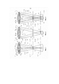
На фиг. 1 схематически показан вид сбоку хирургического светильника согласно предпочтительному варианту реализации настоящего изобретения, на котором четко видны световые лучи двух первых ламп, относящихся к первой группе ламп, в особенности место пересечения этих световых лучей в первой фокальной плоскости, и на котором все (вторые) лампы, относящиеся ко второй группе ламп, находятся в выключенном состоянии.FIG. 1 is a schematic side view of a surgical lamp according to a preferred embodiment of the present invention, in which the light beams of the first two lamps belonging to the first group of lamps are clearly visible, in particular the intersection of these light beams in the first focal plane, and in which all (second) lamps belonging to the second group of lamps are in the off state.
На фиг. 2 схематически показан вид сбоку хирургического светильника по фиг. 1, на котором все первые лампы первой группы ламп находятся в выключенном состоянии, а две вторые лампы второй группы ламп находятся во включенном состоянии, и на котором четко видна общая точка пересечения световых лучей вторых ламп во второй фокальной плоскости, расположенной на некотором расстоянии от первой фокальной плоскости.FIG. 2 is a schematic side view of the surgical light of FIG. 1, in which all the first lamps of the first group of lamps are in the off state, and the two second lamps of the second group of lamps are in the on state, and on which the common point of intersection of the light rays of the second lamps in the second focal plane located at some distance from the first focal plane.
На фиг. 3 схематически показан вид сбоку хирургического светильника по фиг. 1 и 2, на котором две (первые) лампы первой группы ламп и две (вторые) лампы второй группы лампы находятся во включенном состоянии и на котором четко видны перекрывающиеся частные световые поля световых лучей ламп в первой фокальной плоскости.FIG. 3 is a schematic side view of the surgical light of FIG. 1 and 2, in which two (first) lamps of the first group of lamps and two (second) lamps of the second group of lamps are in the on state and in which the overlapping partial light fields of the light rays of the lamps in the first focal plane are clearly visible.
На фиг. 4 схематически показан вид сверху на плоскость освещения, иллюстрирующий лампы из первой и второй групп ламп хирургического светильника, управляемые таким образом, что они обеспечивают формирование суммарного (результирующего) светового поля, проходящего по существу прямолинейно, предпочтительно вдоль горизонтальной оси.FIG. 4 is a schematic top view of an illumination plane illustrating the lamps of the first and second groups of lamps of the surgical light, controlled to produce a net (net) light field that extends substantially in a straight line, preferably along a horizontal axis.
На фиг. 5 показан вид сверху на плоскость освещения по фиг. 4, иллюстрирующий лампы первой и второй групп ламп, управляемые таким образом, что они обеспечивают формирование удлиненного результирующего светового поля, «повернутого» на 45° по сравнению с результирующим световым полем, показанным на фиг. 4.FIG. 5 is a top view of the illumination plane of FIG. 4, illustrating the lamps of the first and second groups of lamps, controlled to produce an elongated resultant light field "rotated" 45 ° from the resultant light field shown in FIG. four.
На фиг. 6 показан вид сверху на плоскость освещения по фиг. 4, иллюстрирующий лампы первой и второй групп ламп, управляемые таким образом, что они обеспечивают формирование по существу Н-образного результирующего светового поля.FIG. 6 is a top view of the illumination plane of FIG. 4, illustrating the lamps of the first and second groups of lamps controlled to produce a substantially H-shaped resulting light field.
На фиг. 7 показан вид сверху на плоскость освещения по фиг. 4, иллюстрирующий лампы первой и второй групп ламп, управляемые таким образом, что они обеспечивают формирование по существу крестообразного результирующего светового поля.FIG. 7 is a top view of the illumination plane of FIG. 4, illustrating the lamps of the first and second groups of lamps, controlled to produce a substantially cruciform resultant light field.
На фиг. 8 показан вид сверху на плоскость освещения по фиг. 4, иллюстрирующий лампы первой и второй групп ламп, управляемые таким образом, что они обеспечивают формирование по существу треугольного результирующего светового поля.FIG. 8 is a top view of the illumination plane of FIG. 4 illustrating the lamps of the first and second groups of lamps controlled to produce a substantially triangular resultant light field.
Чертежи выполнены по существу в схематической форме и предназначены исключительно для пояснения сущности настоящего изобретения. Схожие элементы обозначены одинаковыми ссылочными номерами.The drawings are in substantially schematic form and are intended solely to illustrate the essence of the present invention. Like elements are designated with the same reference numbers.
На фиг. 1 схематически показано изображение хирургического светильника 1 согласно настоящему изобретению. Хирургический светильник 1 обычно используют для освещения или подсвечивания некоторого объекта, например человека, присутствующего на операционном столе. Таким образом, хирургический светильник 1 предназначен для освещения операционной области, т.е. области раны, на объекте.FIG. 1 is a schematic representation of a surgical light 1 according to the present invention. Surgical light 1 is usually used to illuminate or illuminate some object, for example, a person on the operating table. Thus, the surgical light 1 is designed to illuminate the operating area, i. E. the area of the wound, at the facility.
Хирургический светильник 1 содержит несколько отдельных ламп 2. Каждая лампа состоит из одного единственного осветительного модуля, который изготовлен отдельно от остальных ламп 2. Осветительный модуль в свою очередь содержит светодиод и/или электрическую лампочку, и/или светодиод и соответствующую линзу или оптическую систему линз. Лампы 2 в своем осветительном модуле содержат только один светодиод. Кроме того, каждый осветительный модуль содержит соответствующие отражатели и соответствующие устройства для объединения в пучок света, излучаемого светодиодом, так что указанный свет выходит из осветительного модуля с линзовой стороны в форме светового луча 4. Таким образом, каждая лампа 2, находящаяся во включенном состоянии или состоянии питания током формирует световой луч 4, проходящий по продольной оси 3. Другими словами, каждая лампа 2 и, соответственно, каждый осветительный модуль лампы 2 создают световой луч 4.The surgical light 1 contains several
На фиг. 1 схематично показаны две включенные первые лампы 2а, относящиеся к первой группе 5 ламп или первой группе линз. В этой конфигурации первая группа 5 ламп может состоять не только из двух, но и из большего количества первых ламп 2а. Всего в первой группе 5 ламп содержится двенадцать первых ламп 2а. Однако в других конфигурациях количество первых ламп 2а первой группы 5 ламп также может составлять более двенадцати штук или менее двенадцати штук.FIG. 1 schematically shows two
Первые лампы 2а первой группы 5 ламп расположены на кольцевой или круговой периферийной линии, далее называемой первой периферийной линией 10. Первая периферийная линия 10 центрирована по отношению к воображаемой центральной оси 11 хирургического светильника 1. Во время работы центральная ось 11 хирургического светильника 1 образует центральную ось 11 плафона хирургического светильника 1, который для наглядности подробно здесь не представлен. Плафон представляет собой элемент, на котором размещены и/или закреплены несколько ламп 2. Таким образом, на плафоне закреплены все лампы 2. Кроме того, центральная ось 11 также является осью, находящейся в центре плафона хирургического светильника 1 и проходящей по существу вдоль рукоятки хирургического светильника 1, которая для наглядности подробно здесь не представлена. В частности, центральная ось 11 является осью, вдоль которой проходит захватываемая часть рукоятки в форме стержня, за которую может взяться оперирующий хирург.The
Таким образом, первые лампы 2а первой группы 5 ламп размещены или установлены цепочкой в ряд друг за другом в периферийном направлении по отношению к центральной оси 11. Все первые лампы 2а выровнены под углом относительно центральной оси 11 таким образом, что все их продольные оси 3 (продольные оси 3 являются осями, вдоль которых проходит световой луч 4) пересекаются в общем месте пересечения, называемом в данном документе первым местом 12 пересечения, находящимся в общей первой фокальной плоскости 6. Таким образом, все продольные оси 3 первых ламп 2а проходят под одним и тем же углом к центральной оси 11. Таким образом, из осветительного модуля ламп 2а соответствующий световой луч 4 всегда проходит по отношению к центральной оси 11 таким образом, что в первой фокальной плоскости образовано общее место фокусировки и/или общее место пересечения, т.е. первое место 12 пересечения. Поскольку все первые лампы 2а первой группы 5 ламп во включенном состоянии пересекаются друг с другом, перекрывают друг друга или накладываются друг на друга в общем первом месте 12 пересечения, находящемся в первой фокальной плоскости 6, они обеспечивают формирование общего первого круглого фокального светового поля 13. Первое фокальное световое поле 13 имеет наибольший первый диаметр, составляющий приблизительно 300 мм.Thus, the
На фиг. 1 схематически показаны две первые лампы 2а, расположенные напротив друг друга по отношению к центральной оси 11 и включенные, так что одна из первых ламп 2а создает первый световой луч 4, проходящий вдоль первой продольной оси За, а другая первая лампа 2а, расположенная со смещением на 180° вдоль первой периферийной линии 10, создает второй световой луч 4b, проходящий вдоль второй продольной оси 3b. Два световых луча 4а, 4b сходятся до первого места 12 пересечения, а в дальнейшем, со стороны первой фокальной плоскости 6, обращенной от хирургического светильника 1, расходятся, если смотреть под одним и тем же углом (применительно к величине угла) между соответствующей продольной осью За, 3b и центральной осью 11.FIG. 1 schematically shows two
В первой плоскости 7 освещения, расположенной на расстоянии от первой фокальной плоскости 6, для простоты также называемой плоскостью освещения, каждый из световых лучей 4а и 4b двух первых ламп 2а формирует или освещает частное световое поле 19.In a first illumination plane 7 located at a distance from the first focal plane 6, also called illumination plane for simplicity, each of the
Как показано на фиг. 2, помимо первой группы 5 ламп, образованной из первых ламп 2а, имеется вторая группа 8 ламп или линз, которая в свою очередь содержит несколько ламп 2. Лампы 2, называемые вторыми лампами 2b второй группы 8 ламп, имеют такие же конструкцию и функциональное назначение, что и первые лампы 2а. Таким образом, каждая из вторых ламп 2b также содержит осветительный модуль, содержащий только один светодиод и одну линзу, связанную с указанным светодиодом.As shown in FIG. 2, in addition to the
Вторые лампы 2b из второй группы 8 ламп расположены радиально снаружи по отношению к первым лампам 2а первой группы 5 ламп, если смотреть по отношению к центральной оси 11. Вторые лампы 2b также расположены по кругу друг за другом по периферийной линии, называемой далее второй периферийной линией 14. Таким образом, вторые лампы 2b также расположены в периферийном направлении относительно центральной оси 11. Следовательно, вторая периферийная линия 14 имеет диаметр, превышающий диаметр первой периферийной линии 10.The
Кроме того, во второй группе 8 ламп могут быть использованы не только две (вторые) лампы 2b, но и большее количество ламп 2b. Всего вторая группа 8 ламп содержит восемнадцать вторых ламп 2b, установленных цепочкой в ряд друг за другом вдоль кольцевой второй периферийной линии 14. Однако, в других конфигурациях во второй группе 8 ламп может быть использовано и иное количество вторых ламп 2b, например более восемнадцати или менее восемнадцати вторых ламп 2b. Кроме того, следует отметить, что лампы 2а и 2b двух групп 5 и 8 ламп, первой и второй, не обязательно должны быть расположены по кругу, проходящему по кольцевой периферийной линии 10, 14. Группы 5, 8 ламп могут быть также расположены и иным образом без выхода за пределы сущности настоящего изобретения.In addition, in the
Согласно фиг. 2, очевидно, что все вторые лампы 2b в свою очередь ориентированы в сторону центральной оси 11. Как и в предыдущем примере, продольные оси 3 световых лучей 4 всех вторых ламп 2b проходят под углом к центральной оси 11. Продольные оси 3 всех вторых ламп 2b проходят под одним и тем же углом к центральной оси 11.As shown in FIG. 2, it is obvious that all the
На фиг. 2, как и в предыдущем примере, схематически показаны две включенные лампы 2b, которые по существу расположены напротив друг друга под углом 180° ко второй периферийной линии 14. Одна из двух вторых ламп 2b создает световой луч 4, называемый третьим световым лучом 4 с, который проходит вдоль третьей продольной оси 3с. Другая из двух ламп 2b во включенном состоянии в свою очередь создает четвертый световой луч 4d, проходящий вдоль четвертой продольной оси 3d. Две вторые лампы 2b установлены по отношению друг к другу таким образом, что их продольные оси 3с и 3d пересекаются в общей фокальной точке или общем месте пересечения, называемом в данном документе вторым местом 15 пересечения. Второе место 15 пересечения находится во второй фокальной плоскости 9, расположенной на расстоянии от первой фокальной плоскости 6. Кроме того, не только продольные оси 3с, 3d включенных вторых ламп 2b, показанных на фиг. 2, но и продольные оси 3 всех вторых ламп 2b, входящих во вторую группу 8 ламп, пересекаются в общем месте 15 пересечения во второй фокальной плоскости 9.FIG. 2, as in the previous example, two
В этой конфигурации каждая фокальная плоскость 6 и 9 представляет собой плоскость, перпендикулярную центральной оси 11. В этом варианте реализации вторая фокальная плоскость 9 образует первую плоскость 7 освещения первой группы 5 ламп. Первая фокальная плоскость 6 в свою очередь образует (вторую) плоскость 17 освещения для второй группы 8 ламп, вследствие чего два световых луча 4с, 4d двух вторых ламп 2b во второй плоскости 17 освещения, как и в предыдущем примере, формируют два частных световых поля 19, расположенных на расстоянии друг от друга. Поскольку все вторые лампы 2а во включенном состоянии пересекаются друг с другом, перекрывают друг друга или накладываются друг на друга во втором общем месте 15 пересечения, лампы формируют общее (второе) круговое фокальное световое поле 16 во второй фокальной плоскости 9. Второе фокальное световое поле 16 может иметь наибольший второй диаметр, составляющий приблизительно 150 мм. Таким образом, во второй плоскости 17 освещения, расположенной на расстоянии от второй фокальной плоскости 9 и соответствующей первой фокальной плоскости 6, две лампы 2b формируют круговые частные световые поля 19, расположенные на расстоянии друг от друга.In this configuration, each focal plane 6 and 9 is a plane perpendicular to the
Согласно приведенному ниже описанию, первая фокальная плоскость 6 расположена ближе к хирургическому светильнику 1, т.е. к плафону хирургического светильника 1, чем вторая фокальная плоскость 9, если смотреть вдоль центральной оси 11. Таким образом, первая фокальная плоскость 6 расположена на меньшем расстоянии по центральной оси 11 по отношению к хирургическому светильнику 1 или плафону, чем вторая фокальная плоскость 9. В одном из особо предпочтительных вариантов реализации расстояние от хирургического светильника 1 или плафона до первой фокальной плоскости 6 по центральной оси 11 составляет 1 м, а расстояние от хирургического светильника 1 или плафона до второй фокальной плоскости 9 по центральной оси 11 составляет 1,20 м, предпочтительно 1,40 м.As described below, the first focal plane 6 is located closer to the surgical light 1, i. E. to the plafond of the surgical lamp 1 than the second focal plane 9, when viewed along the
Согласно фиг. 3, две первые лампы 2а, показанные во включенном состоянии на фиг. 1, и две вторые лампы 2b, показанные во включенном состоянии на фиг. 2, одновременно включают с формированием удлиненного результирующего светового поля 20 в первой фокальной плоскости 6, соответствующей второй плоскости 17 освещения, и во второй фокальной плоскости 9, соответствующей первой плоскости 7 освещения. Таким образом, в результате подачи тока на первые и/или вторые лампы 2а, 2b сформировано результирующее световое поле, имеющее конкретную схему светового поля или геометрическую форму 18 светового поля, при этом геометрическая форма 18 светового поля (т.е. геометрическая форма результирующего светового поля 20) или результирующее световое поле 20 сформированы из отдельных частных световых полей 19 отдельных ламп 2а, 2b.As shown in FIG. 3, the two
Согласно настоящему изобретению, отдельные лампы 2а и 2b соответственно первой группы 5 ламп и второй группы 8 ламп можно питать током, т.е. ими можно электрически управлять или их можно включать независимо друг от друга в пределах группы, а также между группами, так что геометрическая форма создаваемого результирующего светового поля 20 может быть отрегулирована по желанию, например в соответствующей плоскости 7, 17 освещения. В данном контексте под регулировкой геометрической формы понимают изменение формы и размеров результирующего светового поля 20 (т.е. геометрической формы 18 светового поля) и изменение ориентации результирующего светового поля 20 (т.е. геометрической формы 18 светового поля) в плоскости 7, 17 освещения. Различные возможные геометрические формы 18 светового поля показаны на фиг. 4-8.According to the present invention, the
Для управления отдельными лампами 2 в хирургическом светильнике 1, а именно внутри плафона, имеется центральный блок управления, который для наглядности подробно здесь не представлен и который электрически соединен с (первыми) лампами 2а первой группы 5 ламп и (вторыми) лампами 2b второй группы 8 ламп. Кроме того, блок управления предпочтительно оборудован датчиками освещенности, расположенными, например, в плафоне или в рукоятке хирургического светильника 1. Датчики освещенности определяют мгновенную освещенность в области раны с выдачей в блок управления сигналов, позволяющих рассчитать, является ли освещение области раны слишком ярким или слишком темным. Таким образом, блок управления может генерировать управляющую команду, передаваемую в группы 5, 8 ламп, и уменьшать яркость и/или выключать отдельные лампы 2 или все лампы или увеличивать яркость и/или включать отдельные лампы 2 или все лампы. Кроме того, на основании этого датчики освещенности в свою очередь позволяют сделать о том, какая геометрическая форма 18 светового поля, показанного, например, на фиг. 4-8, наиболее подходит для соответствующей области раны.To control the
Кроме того, следует отметить, что управление или регулировка яркости или освещенности ламп 2а первой группы 5 ламп и/или ламп 2b второй группы 8 ламп могут быть осуществлены независимо друг от друга. Кроме того, лампы 2а первой группы 5 ламп и/или лампы 2b второй группы 8 ламп можно включать и выключать независимо друг от друга. Несмотря на то, что одна из первых ламп 2а имеет первую яркость или освещенность, другая первая лампа 2а может иметь другую яркость или освещенность, например более высокую яркость или освещенность.In addition, it should be noted that the control or regulation of the brightness or illumination of the
Кроме того, лампы 2а и 2b соответственно из отдельных групп 5 и 8 ламп могут отличаться друг от друга или в разных группах по своему цвету освещения. Несмотря на то, что некоторые из первых ламп 2а создают, например, частное голубоватое световое поле 19, другие первые лампы 2а могут создавать частное оранжевое световое поле 19.In addition,
На фиг. 4 показан пример первой геометрической формы 18 светового поля в плоскости освещения, соответствующей первой плоскости 7 освещения. В этом случае первые лампы 2а и вторые лампы 2b (при нахождении блока управления в первом состоянии управления) включены с получением трех частных световых полей 19, при этом по меньшей мере центральное частное световое поле 19 является вторым фокальным световым полем 16 (сформированным вторыми лампами 2b). Частные световые поля 19 частично перекрывают друг друга с получением вытянутого результирующего светового поля 20. Таким образом, результирующее световое поле 20 образует удлиненную первую геометрическую форму 18 светового поля.FIG. 4 shows an example of a first light field geometry 18 in the illumination plane corresponding to the first illumination plane 7. In this case, the
На фиг. 5 показана вторая геометрическая форма 18 светового поля в первой плоскости 7 освещения, при этом первые лампы 2а и вторые лампы 2b включены и/или запитаны током (при нахождении блока управления во втором состоянии управления) с получением трех частных световых полей 19, проходящих по воображаемой оси протяженности с созданием удлиненной (второй) геометрической формы 18 светового поля. Однако первые лампы 2а в отличие от показанных на фиг. 4, включены таким образом, что вторая геометрическая форма 18 светового поля повернута по отношению к первой геометрической форме светового поля, показанной на фиг. 4, а именно повернута против часовой стрелки приблизительно на 45 градусов.FIG. 5 shows the second geometric shape 18 of the light field in the first illumination plane 7, wherein the
На фиг. 6 показан пример, в котором помимо первых ламп 2а и вторых ламп 2b (при нахождении блока управления в третьем состоянии управления) включены дополнительные лампы 2 из других групп ламп, которые для наглядности подробно здесь не представлены, но работают аналогично первой группе ламп. Таким образом, получают Н-образное результирующее световое поле 20, состоящее из семи частных световых полей. Таким образом, результирующее световое поле 20 имеет Н-образную третью геометрическую форму 18 светового поля.FIG. 6 shows an example in which, in addition to the
На фиг. 7 показан пример, в котором первые лампы 2а и вторые лампы 2b включены и/или запитаны током (при нахождении блока управления в четвертом состоянии управления) с формированием четвертой крестообразной геометрической формы 18 светового поля.FIG. 7 shows an example in which the
На фиг. 8 показан пример, в котором первые лампы 2а и вторые лампы 2b включены и/или запитаны током (при нахождении блока управления в пятом состоянии управления) с формированием пятой треугольной геометрической формы 18 светового поля.FIG. 8 shows an example in which the
Кроме того, к блоку управления может быть подключен функциональный блок. Функциональный блок предназначен для регулировки геометрической формы 18 светового поля, необходимой оперирующему хирургу и/или пользователю. Функциональный блок подключен к блоку управления, например, посредством проводной или беспроводной сети передачи данных, например посредством беспроводной сети передачи данных типа «Bluetooth», с возможностью передачи данных.In addition, a function block can be connected to the control unit. The functional block is designed to adjust the geometric shape 18 of the light field required by the operating surgeon and / or the user. The functional unit is connected to the control unit, for example, by means of a wired or wireless data transmission network, for example, by means of a wireless data transmission network of the "Bluetooth" type, with the possibility of data transmission.
В другой конфигурации функциональный блок дополнительно содержит блок распознавания речи, позволяющий регулировать геометрическую форму 19 светового поля с использованием устройства речевого ввода. Кроме того, функциональным блоком можно управлять с использованием «приложения», установленного на мобильном оборудовании, таком как смартфон или планшетный ПК, и представленного в виде ползункового регулятора, посредством которого возможно отрегулировать геометрическую форму 18 светового поля.In another configuration, the functional unit further comprises a speech recognition unit for adjusting the
Другими словами, хирургический светильник 1 согласно настоящему изобретению снабжен несколькими источниками света (светодиодами или светоизлучающими диодами) в лампах 2 и/или осветительном модуле ламп 2. Каждый источник 2 света содержит оптическую систему. Источники 2 света представляют собой светодиоды. Все источники 2 света направлены в сторону основной и/или центральной оси 11 хирургического светильника 1. Часть А источников света (первые лампы 2а первой группы 5 ламп), расположенных в центре хирургического светильника 1, собирают свет на расстоянии X от хирургического светильника 1 до освещаемого поля, например на расстоянии 1 м (в первой фокальной плоскости 6). Вторая часть В источников света (вторых ламп 2b второй группы 8 ламп), расположенных вокруг первой части 5 источников света 2а, собирает свет на большем расстоянии Y, например на расстоянии 1,4 м (во второй фокальной плоскости 9). Таким образом, свет от части А, как показано на фиг. 1, формирует небольшое световое поле на расстоянии 1 м, свет от части В, как показано фиг. 2, формирует небольшое световое поле на расстоянии 1,4 м, а свет от частей А и В, как показано на фиг. 3, формирует большое световое поле на расстоянии 1 м, так что свет от части В дополнен светом от части А. В равной степени происходит улучшение освещения по глубине, поскольку одновременно с этим вследствие формирования светового поля (фокальных световых полей 13, 16) на расстоянии X и Y происходит образование фокальных каскадов.In other words, the surgical light 1 according to the present invention is provided with multiple light sources (LEDs or light emitting diodes) in the
В идеале этот принцип может быть расширен дополнительными световыми областями С и, следовательно, дополнительными световыми полями и расстояниями Z. Удлиненное или овальное световое поле (результирующее световое поле 20) может быть создано путем управления отдельными источниками света (первыми лампами 2а) из области А и источниками света из области В (вторыми лампами 2b), которые расположены в продольном направлении. При индивидуальном управлении каждым светодиодом хирургического светильника 1 (матричное управление) можно изменять продольное направление и поворачивать удлиненное световое поле 20 в сетке матрицы светодиодов, показанной на фиг. 4 и 5. Кроме того, возможны и дополнительные фигуры, такие как фигуры, показанные фиг. 6 и 7, и асимметричная фигура, показанная на фиг. 8.Ideally, this principle can be extended with additional light areas C and therefore additional light fields and distances Z. An elongated or oval light field (resulting light field 20) can be created by controlling individual light sources (
Перечень ссылочных номеровList of reference numbers
1 хирургический светильник1 surgical light
2 лампы2 lights
2а первая лампа2a first lamp
2b вторая лампа2b second lamp
3 продольная ось3 longitudinal axis
3а первая продольная ось3a first longitudinal axis
3b вторая продольная ось3b second longitudinal axis
3с третья продольная ось3c third longitudinal axis
3d четвертая продольная ось3d fourth longitudinal axis
4 световой луч4 light beam
4а первый световой луч4a first light beam
4b второй световой луч4b second light beam
4с третий световой луч4s third light beam
4d четвертый световой луч4d fourth light beam
5 первая группа ламп5 first group of lamps
6 первая фокальная плоскость6 first focal plane
7 первая плоскость освещения или плоскость освещения7 first illumination plane or illumination plane
8 вторая группа ламп8 second group of lamps
9 вторая фокальная плоскость9 second focal plane
10 первая периферийная линия10 first peripheral line
11 центральная ось11 central axis
12 первое место пересечения12 first crossing point
13 первое фокальное световое поле13 first focal light field
14 вторая периферийная линия14 second peripheral line
15 второе место пересечения15 second crossing point
16 второе фокальное световое поле16 second focal light field
17 вторая плоскость освещения17 second illumination plane
18 геометрическая форма светового поля или компоновка светового поля18 geometric shape of the light field or arrangement of the light field
19 частное световое поле19 private light field
20 результирующее световое поле20 resulting light field
Claims (13)
Applications Claiming Priority (3)
| Application Number | Priority Date | Filing Date | Title |
|---|---|---|---|
| DE102015113337.7 | 2015-08-13 | ||
| DE102015113337.7A DE102015113337A1 (en) | 2015-08-13 | 2015-08-13 | Operating light with variable light field geometry |
| PCT/EP2016/068892 WO2017025512A1 (en) | 2015-08-13 | 2016-08-08 | Surgical light having a variable light field geometry |
Publications (3)
| Publication Number | Publication Date |
|---|---|
| RU2018108892A RU2018108892A (en) | 2019-09-16 |
| RU2018108892A3 RU2018108892A3 (en) | 2020-02-19 |
| RU2749315C2 true RU2749315C2 (en) | 2021-06-08 |
Family
ID=56684651
Family Applications (1)
| Application Number | Title | Priority Date | Filing Date |
|---|---|---|---|
| RU2018108892A RU2749315C2 (en) | 2015-08-13 | 2016-08-08 | Surgical lamp with adjustable geometric shape of light field |
Country Status (9)
| Country | Link |
|---|---|
| US (1) | US10624713B2 (en) |
| EP (1) | EP3335526B1 (en) |
| CN (1) | CN108029168B (en) |
| AU (1) | AU2016305252B2 (en) |
| BR (1) | BR112018002680B1 (en) |
| CA (1) | CA2995137A1 (en) |
| DE (1) | DE102015113337A1 (en) |
| RU (1) | RU2749315C2 (en) |
| WO (1) | WO2017025512A1 (en) |
Cited By (1)
| Publication number | Priority date | Publication date | Assignee | Title |
|---|---|---|---|---|
| RU2775731C1 (en) * | 2021-11-09 | 2022-07-07 | Общество с ограниченной ответственностью "Эльбрус" (ООО "Эльбрус") | Method for regulating the geometric shape of the light field and a surgical lamp for its implementation |
Families Citing this family (6)
| Publication number | Priority date | Publication date | Assignee | Title |
|---|---|---|---|---|
| DE102015113337A1 (en) * | 2015-08-13 | 2017-02-16 | Karl Leibinger Medizintechnik Gmbh & Co. Kg | Operating light with variable light field geometry |
| WO2019155426A1 (en) * | 2018-02-09 | 2019-08-15 | Gentex Corporation | Adaptive lighting array with image-based control |
| WO2019155425A1 (en) | 2018-02-09 | 2019-08-15 | Gentex Corporation | Systems and methods for detection and illumination of regions of interest |
| FR3087721B1 (en) * | 2018-10-24 | 2021-07-30 | Valeo Vision | SYSTEM AND METHOD FOR LIGHTING A SIDE REGION OF A VEHICLE |
| DE102021108309A1 (en) | 2021-04-01 | 2022-10-06 | Drägerwerk AG & Co. KGaA | lighting unit and lamp |
| WO2023098700A1 (en) * | 2021-12-03 | 2023-06-08 | Intelligent Precision Micro-Systems Limited | Mechanical arm |
Citations (7)
| Publication number | Priority date | Publication date | Assignee | Title |
|---|---|---|---|---|
| US4196460A (en) * | 1978-07-14 | 1980-04-01 | Sybron Corporation | Major surgical light |
| US6591239B1 (en) * | 1999-12-09 | 2003-07-08 | Steris Inc. | Voice controlled surgical suite |
| US20080247163A1 (en) * | 2007-04-04 | 2008-10-09 | Lien-Chen Chen | Operating lamp with adjustable light sources capable of generating a light field of a gaussian distribution |
| EP2136126A1 (en) * | 2008-06-20 | 2009-12-23 | TRUMPF Medizin Systeme GmbH + Co. KG | Operating light |
| RU2413475C2 (en) * | 2006-01-24 | 2011-03-10 | Закрытое акционерное общество "Завод "ЭМА" | Surgical light with controlled optical radiation |
| US20120075832A1 (en) * | 2010-09-28 | 2012-03-29 | Trumpf Medizin Systeme Gmbh + Co. Kg | Surgical Lamps and Related Systems and Methods |
| US20140066722A1 (en) * | 2011-03-02 | 2014-03-06 | Trumpf Medizin Systeme Gmbh + Co. Kg | Surgical Lamps and Methods for Illuminating Operating Sites |
Family Cites Families (26)
| Publication number | Priority date | Publication date | Assignee | Title |
|---|---|---|---|---|
| DE1197827C2 (en) * | 1964-04-11 | 1976-02-26 | Orginal Hanau Quarzlampen GmbH, 6450 Hanau | SURGICAL LIGHT |
| US6585395B2 (en) * | 2001-03-22 | 2003-07-01 | Altman Stage Lighting Co., Inc. | Variable beam light emitting diode light source system |
| US6880957B2 (en) * | 2002-03-28 | 2005-04-19 | Mark Wayne Walters | Lighting apparatus with electronic shadow compensation |
| EP1568934B1 (en) * | 2004-02-28 | 2012-05-30 | TRUMPF Medizin Systeme GmbH + Co. KG | Surgical light |
| ATE357627T1 (en) * | 2004-02-28 | 2007-04-15 | Trumpf Kreuzer Med Sys Gmbh | OPERATIONAL LIGHT |
| ATE384911T1 (en) | 2005-05-14 | 2008-02-15 | Trumpf Kreuzer Med Sys Gmbh | OPERATIONAL LIGHT WITH ZONE-WISE INTENSITY CONTROL |
| US7725024B2 (en) * | 2005-07-08 | 2010-05-25 | Electro Scientific Industries, Inc. | Optimizing use and performance of optical systems implemented with telecentric on-axis dark field illumination |
| EA011462B1 (en) * | 2006-01-24 | 2009-04-28 | Закрытое Акционерное Общество "Завод Эма" | Surgical light provided with a light emission control |
| DE202007007054U1 (en) * | 2006-11-15 | 2007-07-26 | Trumpf Kreuzer Medizin Systeme Gmbh + Co. Kg | Operation lighting system, has control device for adjusting color temperature of operation lamp, and camera for recording operation, where adjusted temperature is transmitted to camera that is connected with control device by data cable |
| DE202007015823U1 (en) * | 2006-11-24 | 2008-03-27 | Karl Leibinger Medizintechnik Gmbh & Co. Kg | Operating or examination light |
| WO2008087404A1 (en) * | 2007-01-18 | 2008-07-24 | Brandon Medical Company Limited | Illumination device |
| CN101025257A (en) * | 2007-03-16 | 2007-08-29 | 汕头市夏野电器有限公司 | Colour, temperature adjustable operation lamp |
| US7841741B2 (en) * | 2007-04-02 | 2010-11-30 | Endicott Interconnect Technologies, Inc. | LED lighting assembly and lamp utilizing same |
| PL2136128T3 (en) * | 2008-06-20 | 2011-06-30 | Trumpf Medizin Systeme Gmbh & Co Kg | Operating light |
| US20100097802A1 (en) * | 2008-10-20 | 2010-04-22 | Robe Lighting S.R.O. | Light collection system for an led luminaire |
| DE102009037316A1 (en) | 2009-08-14 | 2011-02-17 | Karl Storz Gmbh & Co. Kg | Control and method for operating a surgical light |
| US9109787B2 (en) * | 2012-01-25 | 2015-08-18 | Hubbell Incorporated | Circular LED optic and heat sink module |
| FR3005339A1 (en) * | 2013-05-03 | 2014-11-07 | Maquet Sas | LIGHTING DEVICE FOR FORMING A VARIABLE COLOR DIAMETER AND TEMPERATURE ILLUMINATION TASK |
| WO2015191869A1 (en) * | 2014-06-12 | 2015-12-17 | Westland Jones Technologies, Llc | System, devices, and methods for illumination including solid-state light emitting devices |
| KR101839034B1 (en) * | 2014-10-01 | 2018-03-16 | 한국전자통신연구원 | Astral lamp apparatus using detachable and angle-controllable led module blocks and method for setting thereof |
| DE102015004969B4 (en) * | 2015-04-20 | 2016-12-22 | Drägerwerk AG & Co. KGaA | Operating light for generating a total light field consisting of partial light fields |
| FR3037121B1 (en) * | 2015-06-02 | 2017-06-16 | Maquet Sas | LIGHTING DEVICE WITH REDUCED DIMENSION LIGHTING COVER TO FORM A VARIABLE COLOR DIAMETER AND TEMPERATURE LIGHTING TASK |
| DE102015113339A1 (en) * | 2015-08-13 | 2017-02-16 | Karl Leibinger Medizintechnik Gmbh & Co. Kg | Operating light with brightness control |
| DE102015113337A1 (en) * | 2015-08-13 | 2017-02-16 | Karl Leibinger Medizintechnik Gmbh & Co. Kg | Operating light with variable light field geometry |
| WO2017205978A1 (en) * | 2016-05-31 | 2017-12-07 | Holdsworth David W | Gamma probe and multimodal intraoperative imaging system |
| FR3055688B1 (en) * | 2016-09-05 | 2018-09-07 | Maquet Sas | MEDICAL LIGHTING DEVICE WITH LEDS ORIENTED BY PRE-CUTTED TONGUES IN A PRINTED CIRCUIT BOARD |
-
2015
- 2015-08-13 DE DE102015113337.7A patent/DE102015113337A1/en not_active Ceased
-
2016
- 2016-08-08 BR BR112018002680-8A patent/BR112018002680B1/en active IP Right Grant
- 2016-08-08 RU RU2018108892A patent/RU2749315C2/en active
- 2016-08-08 CN CN201680046646.0A patent/CN108029168B/en active Active
- 2016-08-08 WO PCT/EP2016/068892 patent/WO2017025512A1/en active Application Filing
- 2016-08-08 AU AU2016305252A patent/AU2016305252B2/en active Active
- 2016-08-08 EP EP16751279.7A patent/EP3335526B1/en active Active
- 2016-08-08 US US15/751,344 patent/US10624713B2/en active Active
- 2016-08-08 CA CA2995137A patent/CA2995137A1/en not_active Abandoned
Patent Citations (8)
| Publication number | Priority date | Publication date | Assignee | Title |
|---|---|---|---|---|
| US4196460A (en) * | 1978-07-14 | 1980-04-01 | Sybron Corporation | Major surgical light |
| US6591239B1 (en) * | 1999-12-09 | 2003-07-08 | Steris Inc. | Voice controlled surgical suite |
| RU2413475C2 (en) * | 2006-01-24 | 2011-03-10 | Закрытое акционерное общество "Завод "ЭМА" | Surgical light with controlled optical radiation |
| US20080247163A1 (en) * | 2007-04-04 | 2008-10-09 | Lien-Chen Chen | Operating lamp with adjustable light sources capable of generating a light field of a gaussian distribution |
| EP2136126A1 (en) * | 2008-06-20 | 2009-12-23 | TRUMPF Medizin Systeme GmbH + Co. KG | Operating light |
| US20090318771A1 (en) * | 2008-06-20 | 2009-12-24 | Trumpf Medizin Systeme Gmbh + Co. Kg | Surgical lamp field shape |
| US20120075832A1 (en) * | 2010-09-28 | 2012-03-29 | Trumpf Medizin Systeme Gmbh + Co. Kg | Surgical Lamps and Related Systems and Methods |
| US20140066722A1 (en) * | 2011-03-02 | 2014-03-06 | Trumpf Medizin Systeme Gmbh + Co. Kg | Surgical Lamps and Methods for Illuminating Operating Sites |
Cited By (1)
| Publication number | Priority date | Publication date | Assignee | Title |
|---|---|---|---|---|
| RU2775731C1 (en) * | 2021-11-09 | 2022-07-07 | Общество с ограниченной ответственностью "Эльбрус" (ООО "Эльбрус") | Method for regulating the geometric shape of the light field and a surgical lamp for its implementation |
Also Published As
| Publication number | Publication date |
|---|---|
| RU2018108892A3 (en) | 2020-02-19 |
| CN108029168B (en) | 2020-07-03 |
| BR112018002680B1 (en) | 2022-11-01 |
| AU2016305252A1 (en) | 2018-03-08 |
| CN108029168A (en) | 2018-05-11 |
| US20180228569A1 (en) | 2018-08-16 |
| RU2018108892A (en) | 2019-09-16 |
| BR112018002680A2 (en) | 2018-10-02 |
| WO2017025512A1 (en) | 2017-02-16 |
| CA2995137A1 (en) | 2017-02-16 |
| EP3335526A1 (en) | 2018-06-20 |
| DE102015113337A1 (en) | 2017-02-16 |
| AU2016305252B2 (en) | 2021-09-09 |
| EP3335526B1 (en) | 2021-12-08 |
| US10624713B2 (en) | 2020-04-21 |
Similar Documents
| Publication | Publication Date | Title |
|---|---|---|
| RU2749315C2 (en) | Surgical lamp with adjustable geometric shape of light field | |
| CN107072744B (en) | Surgical lamp and method for operating a surgical lamp | |
| JP4758660B2 (en) | Surgical lighting | |
| JP5697855B2 (en) | Surgical lighting device | |
| JP5804702B2 (en) | Directionally controllable lighting unit | |
| US7513645B2 (en) | Multiple module lamp | |
| DK2673557T3 (en) | Operation lamp and method for illumination of an operation site | |
| US7922347B2 (en) | Surgical light provided with a light emission control | |
| RU2017141620A (en) | MODULAR LIGHTING DEVICE, MODULE FOR THIS DEVICE, SYSTEM AND ILLUMINATOR FOR THIS MODULE | |
| ES2752873T3 (en) | Angular light distribution intensity regulator control | |
| EP3165819B1 (en) | Scialytic led lamp, particularly for operating rooms and the like | |
| CN102458016B (en) | Operating lamp as well as surgery field facula adjusting device and method of operating lamp | |
| US10701772B2 (en) | Lighting device with variable light distribution | |
| US11946621B2 (en) | Integrated optical system for dynamic diffuse and directional lighting | |
| KR101583308B1 (en) | Light source Module, and Medical LED lighting with it | |
| JP2017188231A (en) | LED lamp and lighting device | |
| JP2023525404A (en) | Lighting system and lighting method | |
| JP2012081057A (en) | Medical lighting system | |
| US10219346B2 (en) | Dynamic color shadows for decorative white lighting | |
| RU191645U1 (en) | LED surgical light | |
| KR20160077448A (en) | Multi wavelength selectable lighting device |