RU2746348C2 - Induction device for aerosol delivery - Google Patents
Induction device for aerosol delivery Download PDFInfo
- Publication number
- RU2746348C2 RU2746348C2 RU2019113798A RU2019113798A RU2746348C2 RU 2746348 C2 RU2746348 C2 RU 2746348C2 RU 2019113798 A RU2019113798 A RU 2019113798A RU 2019113798 A RU2019113798 A RU 2019113798A RU 2746348 C2 RU2746348 C2 RU 2746348C2
- Authority
- RU
- Russia
- Prior art keywords
- resonant
- aerosol
- aerosol delivery
- communication device
- delivery device
- Prior art date
Links
- 239000000443 aerosol Substances 0.000 title claims abstract description 243
- 230000006698 induction Effects 0.000 title claims description 3
- 238000004891 communication Methods 0.000 claims abstract description 171
- 239000002243 precursor Substances 0.000 claims abstract description 95
- 239000000203 mixture Substances 0.000 claims abstract description 93
- 239000000758 substrate Substances 0.000 claims abstract description 81
- 230000005291 magnetic effect Effects 0.000 claims abstract description 24
- 230000009471 action Effects 0.000 claims abstract description 10
- 239000007787 solid Substances 0.000 claims description 21
- 239000003990 capacitor Substances 0.000 claims description 19
- HBBGRARXTFLTSG-UHFFFAOYSA-N Lithium ion Chemical compound [Li+] HBBGRARXTFLTSG-UHFFFAOYSA-N 0.000 claims description 10
- 229910001416 lithium ion Inorganic materials 0.000 claims description 10
- 238000005259 measurement Methods 0.000 claims description 7
- 230000005355 Hall effect Effects 0.000 claims description 5
- 230000008020 evaporation Effects 0.000 claims 1
- 238000001704 evaporation Methods 0.000 claims 1
- 230000005284 excitation Effects 0.000 claims 1
- 239000000126 substance Substances 0.000 abstract description 9
- 230000000694 effects Effects 0.000 abstract description 4
- 238000010438 heat treatment Methods 0.000 description 50
- 239000000463 material Substances 0.000 description 27
- 230000000391 smoking effect Effects 0.000 description 24
- 241000208125 Nicotiana Species 0.000 description 23
- 235000002637 Nicotiana tabacum Nutrition 0.000 description 23
- 238000000034 method Methods 0.000 description 21
- 238000007789 sealing Methods 0.000 description 18
- 235000019504 cigarettes Nutrition 0.000 description 12
- 239000000047 product Substances 0.000 description 12
- 239000012530 fluid Substances 0.000 description 11
- 230000007246 mechanism Effects 0.000 description 9
- 239000008263 liquid aerosol Substances 0.000 description 8
- 238000012546 transfer Methods 0.000 description 8
- 235000019506 cigar Nutrition 0.000 description 7
- 239000003571 electronic cigarette Substances 0.000 description 7
- 238000005516 engineering process Methods 0.000 description 7
- 239000011521 glass Substances 0.000 description 7
- 238000012387 aerosolization Methods 0.000 description 6
- 239000007788 liquid Substances 0.000 description 6
- 230000005540 biological transmission Effects 0.000 description 5
- 239000004020 conductor Substances 0.000 description 5
- 239000000919 ceramic Substances 0.000 description 4
- 238000002485 combustion reaction Methods 0.000 description 4
- 230000001276 controlling effect Effects 0.000 description 4
- 239000008275 solid aerosol Substances 0.000 description 4
- OKTJSMMVPCPJKN-UHFFFAOYSA-N Carbon Chemical compound [C] OKTJSMMVPCPJKN-UHFFFAOYSA-N 0.000 description 3
- 238000009825 accumulation Methods 0.000 description 3
- 230000008901 benefit Effects 0.000 description 3
- 229910052799 carbon Inorganic materials 0.000 description 3
- 229920002301 cellulose acetate Polymers 0.000 description 3
- 230000008878 coupling Effects 0.000 description 3
- 238000010168 coupling process Methods 0.000 description 3
- 238000005859 coupling reaction Methods 0.000 description 3
- 238000013461 design Methods 0.000 description 3
- 238000010586 diagram Methods 0.000 description 3
- 230000006870 function Effects 0.000 description 3
- 230000001939 inductive effect Effects 0.000 description 3
- 239000012811 non-conductive material Substances 0.000 description 3
- 239000004033 plastic Substances 0.000 description 3
- 229920003023 plastic Polymers 0.000 description 3
- -1 polyethylene terephthalate Polymers 0.000 description 3
- 229920000139 polyethylene terephthalate Polymers 0.000 description 3
- 239000005020 polyethylene terephthalate Substances 0.000 description 3
- 239000005060 rubber Substances 0.000 description 3
- 239000000779 smoke Substances 0.000 description 3
- 238000003763 carbonization Methods 0.000 description 2
- 230000002500 effect on skin Effects 0.000 description 2
- 230000005672 electromagnetic field Effects 0.000 description 2
- 238000009472 formulation Methods 0.000 description 2
- 239000003205 fragrance Substances 0.000 description 2
- 235000011389 fruit/vegetable juice Nutrition 0.000 description 2
- 239000007789 gas Substances 0.000 description 2
- 239000003365 glass fiber Substances 0.000 description 2
- 238000002347 injection Methods 0.000 description 2
- 239000007924 injection Substances 0.000 description 2
- 239000012212 insulator Substances 0.000 description 2
- 239000007769 metal material Substances 0.000 description 2
- 238000012986 modification Methods 0.000 description 2
- 230000004048 modification Effects 0.000 description 2
- 239000002245 particle Substances 0.000 description 2
- 229910052573 porcelain Inorganic materials 0.000 description 2
- 238000000197 pyrolysis Methods 0.000 description 2
- 230000005855 radiation Effects 0.000 description 2
- 239000012858 resilient material Substances 0.000 description 2
- 230000035807 sensation Effects 0.000 description 2
- 235000019615 sensations Nutrition 0.000 description 2
- 235000019640 taste Nutrition 0.000 description 2
- NOOLISFMXDJSKH-KXUCPTDWSA-N (-)-Menthol Chemical compound CC(C)[C@@H]1CC[C@@H](C)C[C@H]1O NOOLISFMXDJSKH-KXUCPTDWSA-N 0.000 description 1
- RYGMFSIKBFXOCR-UHFFFAOYSA-N Copper Chemical compound [Cu] RYGMFSIKBFXOCR-UHFFFAOYSA-N 0.000 description 1
- NOOLISFMXDJSKH-UHFFFAOYSA-N DL-menthol Natural products CC(C)C1CCC(C)CC1O NOOLISFMXDJSKH-UHFFFAOYSA-N 0.000 description 1
- 230000003213 activating effect Effects 0.000 description 1
- 239000004480 active ingredient Substances 0.000 description 1
- 239000000853 adhesive Substances 0.000 description 1
- 230000001070 adhesive effect Effects 0.000 description 1
- 230000002411 adverse Effects 0.000 description 1
- 239000000956 alloy Substances 0.000 description 1
- 229910045601 alloy Inorganic materials 0.000 description 1
- 229910052782 aluminium Inorganic materials 0.000 description 1
- XAGFODPZIPBFFR-UHFFFAOYSA-N aluminium Chemical compound [Al] XAGFODPZIPBFFR-UHFFFAOYSA-N 0.000 description 1
- 235000019568 aromas Nutrition 0.000 description 1
- 230000015572 biosynthetic process Effects 0.000 description 1
- 239000006227 byproduct Substances 0.000 description 1
- 239000002775 capsule Substances 0.000 description 1
- 229920002678 cellulose Polymers 0.000 description 1
- 239000001913 cellulose Substances 0.000 description 1
- 229910052802 copper Inorganic materials 0.000 description 1
- 239000010949 copper Substances 0.000 description 1
- 238000001514 detection method Methods 0.000 description 1
- 230000005292 diamagnetic effect Effects 0.000 description 1
- 239000002889 diamagnetic material Substances 0.000 description 1
- 239000003814 drug Substances 0.000 description 1
- 229940079593 drug Drugs 0.000 description 1
- 238000012377 drug delivery Methods 0.000 description 1
- 239000003302 ferromagnetic material Substances 0.000 description 1
- 239000000835 fiber Substances 0.000 description 1
- 239000011152 fibreglass Substances 0.000 description 1
- 238000011049 filling Methods 0.000 description 1
- 239000000796 flavoring agent Substances 0.000 description 1
- 235000019634 flavors Nutrition 0.000 description 1
- 230000009969 flowable effect Effects 0.000 description 1
- 230000004907 flux Effects 0.000 description 1
- 235000013305 food Nutrition 0.000 description 1
- 239000007792 gaseous phase Substances 0.000 description 1
- 239000008187 granular material Substances 0.000 description 1
- 239000000696 magnetic material Substances 0.000 description 1
- 230000014759 maintenance of location Effects 0.000 description 1
- 229940041616 menthol Drugs 0.000 description 1
- 229910052751 metal Inorganic materials 0.000 description 1
- 239000002184 metal Substances 0.000 description 1
- 150000002739 metals Chemical class 0.000 description 1
- 238000004806 packaging method and process Methods 0.000 description 1
- 230000005298 paramagnetic effect Effects 0.000 description 1
- 239000002907 paramagnetic material Substances 0.000 description 1
- 238000002161 passivation Methods 0.000 description 1
- 230000035699 permeability Effects 0.000 description 1
- 239000012071 phase Substances 0.000 description 1
- 230000000704 physical effect Effects 0.000 description 1
- 229920000642 polymer Polymers 0.000 description 1
- 229920001296 polysiloxane Polymers 0.000 description 1
- 230000001007 puffing effect Effects 0.000 description 1
- 239000002096 quantum dot Substances 0.000 description 1
- 230000001105 regulatory effect Effects 0.000 description 1
- 239000003566 sealing material Substances 0.000 description 1
- 239000008247 solid mixture Substances 0.000 description 1
- 239000000725 suspension Substances 0.000 description 1
- 239000010409 thin film Substances 0.000 description 1
- 238000002834 transmittance Methods 0.000 description 1
- 238000009834 vaporization Methods 0.000 description 1
- 230000008016 vaporization Effects 0.000 description 1
- 230000000007 visual effect Effects 0.000 description 1
- QYSXJUFSXHHAJI-YRZJJWOYSA-N vitamin D3 Chemical compound C1(/[C@@H]2CC[C@@H]([C@]2(CCC1)C)[C@H](C)CCCC(C)C)=C\C=C1\C[C@@H](O)CCC1=C QYSXJUFSXHHAJI-YRZJJWOYSA-N 0.000 description 1
- 238000003466 welding Methods 0.000 description 1
Images


Classifications
-
- A—HUMAN NECESSITIES
- A24—TOBACCO; CIGARS; CIGARETTES; SIMULATED SMOKING DEVICES; SMOKERS' REQUISITES
- A24F—SMOKERS' REQUISITES; MATCH BOXES; SIMULATED SMOKING DEVICES
- A24F40/00—Electrically operated smoking devices; Component parts thereof; Manufacture thereof; Maintenance or testing thereof; Charging means specially adapted therefor
- A24F40/65—Devices with integrated communication means, e.g. Wi-Fi
-
- A—HUMAN NECESSITIES
- A24—TOBACCO; CIGARS; CIGARETTES; SIMULATED SMOKING DEVICES; SMOKERS' REQUISITES
- A24F—SMOKERS' REQUISITES; MATCH BOXES; SIMULATED SMOKING DEVICES
- A24F40/00—Electrically operated smoking devices; Component parts thereof; Manufacture thereof; Maintenance or testing thereof; Charging means specially adapted therefor
- A24F40/40—Constructional details, e.g. connection of cartridges and battery parts
-
- A—HUMAN NECESSITIES
- A24—TOBACCO; CIGARS; CIGARETTES; SIMULATED SMOKING DEVICES; SMOKERS' REQUISITES
- A24F—SMOKERS' REQUISITES; MATCH BOXES; SIMULATED SMOKING DEVICES
- A24F40/00—Electrically operated smoking devices; Component parts thereof; Manufacture thereof; Maintenance or testing thereof; Charging means specially adapted therefor
- A24F40/20—Devices using solid inhalable precursors
-
- A—HUMAN NECESSITIES
- A24—TOBACCO; CIGARS; CIGARETTES; SIMULATED SMOKING DEVICES; SMOKERS' REQUISITES
- A24F—SMOKERS' REQUISITES; MATCH BOXES; SIMULATED SMOKING DEVICES
- A24F40/00—Electrically operated smoking devices; Component parts thereof; Manufacture thereof; Maintenance or testing thereof; Charging means specially adapted therefor
- A24F40/40—Constructional details, e.g. connection of cartridges and battery parts
- A24F40/46—Shape or structure of electric heating means
- A24F40/465—Shape or structure of electric heating means specially adapted for induction heating
-
- A—HUMAN NECESSITIES
- A24—TOBACCO; CIGARS; CIGARETTES; SIMULATED SMOKING DEVICES; SMOKERS' REQUISITES
- A24F—SMOKERS' REQUISITES; MATCH BOXES; SIMULATED SMOKING DEVICES
- A24F40/00—Electrically operated smoking devices; Component parts thereof; Manufacture thereof; Maintenance or testing thereof; Charging means specially adapted therefor
- A24F40/50—Control or monitoring
- A24F40/51—Arrangement of sensors
-
- A—HUMAN NECESSITIES
- A24—TOBACCO; CIGARS; CIGARETTES; SIMULATED SMOKING DEVICES; SMOKERS' REQUISITES
- A24F—SMOKERS' REQUISITES; MATCH BOXES; SIMULATED SMOKING DEVICES
- A24F40/00—Electrically operated smoking devices; Component parts thereof; Manufacture thereof; Maintenance or testing thereof; Charging means specially adapted therefor
- A24F40/50—Control or monitoring
- A24F40/57—Temperature control
-
- A—HUMAN NECESSITIES
- A24—TOBACCO; CIGARS; CIGARETTES; SIMULATED SMOKING DEVICES; SMOKERS' REQUISITES
- A24F—SMOKERS' REQUISITES; MATCH BOXES; SIMULATED SMOKING DEVICES
- A24F40/00—Electrically operated smoking devices; Component parts thereof; Manufacture thereof; Maintenance or testing thereof; Charging means specially adapted therefor
- A24F40/90—Arrangements or methods specially adapted for charging batteries thereof
- A24F40/95—Arrangements or methods specially adapted for charging batteries thereof structurally associated with cases
-
- A—HUMAN NECESSITIES
- A61—MEDICAL OR VETERINARY SCIENCE; HYGIENE
- A61M—DEVICES FOR INTRODUCING MEDIA INTO, OR ONTO, THE BODY; DEVICES FOR TRANSDUCING BODY MEDIA OR FOR TAKING MEDIA FROM THE BODY; DEVICES FOR PRODUCING OR ENDING SLEEP OR STUPOR
- A61M11/00—Sprayers or atomisers specially adapted for therapeutic purposes
- A61M11/04—Sprayers or atomisers specially adapted for therapeutic purposes operated by the vapour pressure of the liquid to be sprayed or atomised
- A61M11/041—Sprayers or atomisers specially adapted for therapeutic purposes operated by the vapour pressure of the liquid to be sprayed or atomised using heaters
- A61M11/042—Sprayers or atomisers specially adapted for therapeutic purposes operated by the vapour pressure of the liquid to be sprayed or atomised using heaters electrical
-
- H—ELECTRICITY
- H01—ELECTRIC ELEMENTS
- H01G—CAPACITORS; CAPACITORS, RECTIFIERS, DETECTORS, SWITCHING DEVICES OR LIGHT-SENSITIVE DEVICES, OF THE ELECTROLYTIC TYPE
- H01G11/00—Hybrid capacitors, i.e. capacitors having different positive and negative electrodes; Electric double-layer [EDL] capacitors; Processes for the manufacture thereof or of parts thereof
- H01G11/04—Hybrid capacitors
- H01G11/06—Hybrid capacitors with one of the electrodes allowing ions to be reversibly doped thereinto, e.g. lithium ion capacitors [LIC]
-
- H—ELECTRICITY
- H01—ELECTRIC ELEMENTS
- H01M—PROCESSES OR MEANS, e.g. BATTERIES, FOR THE DIRECT CONVERSION OF CHEMICAL ENERGY INTO ELECTRICAL ENERGY
- H01M10/00—Secondary cells; Manufacture thereof
- H01M10/05—Accumulators with non-aqueous electrolyte
- H01M10/052—Li-accumulators
- H01M10/0525—Rocking-chair batteries, i.e. batteries with lithium insertion or intercalation in both electrodes; Lithium-ion batteries
-
- H—ELECTRICITY
- H02—GENERATION; CONVERSION OR DISTRIBUTION OF ELECTRIC POWER
- H02J—CIRCUIT ARRANGEMENTS OR SYSTEMS FOR SUPPLYING OR DISTRIBUTING ELECTRIC POWER; SYSTEMS FOR STORING ELECTRIC ENERGY
- H02J50/00—Circuit arrangements or systems for wireless supply or distribution of electric power
- H02J50/10—Circuit arrangements or systems for wireless supply or distribution of electric power using inductive coupling
- H02J50/12—Circuit arrangements or systems for wireless supply or distribution of electric power using inductive coupling of the resonant type
-
- H—ELECTRICITY
- H02—GENERATION; CONVERSION OR DISTRIBUTION OF ELECTRIC POWER
- H02M—APPARATUS FOR CONVERSION BETWEEN AC AND AC, BETWEEN AC AND DC, OR BETWEEN DC AND DC, AND FOR USE WITH MAINS OR SIMILAR POWER SUPPLY SYSTEMS; CONVERSION OF DC OR AC INPUT POWER INTO SURGE OUTPUT POWER; CONTROL OR REGULATION THEREOF
- H02M7/00—Conversion of ac power input into dc power output; Conversion of dc power input into ac power output
- H02M7/42—Conversion of dc power input into ac power output without possibility of reversal
- H02M7/44—Conversion of dc power input into ac power output without possibility of reversal by static converters
- H02M7/48—Conversion of dc power input into ac power output without possibility of reversal by static converters using discharge tubes with control electrode or semiconductor devices with control electrode
- H02M7/53—Conversion of dc power input into ac power output without possibility of reversal by static converters using discharge tubes with control electrode or semiconductor devices with control electrode using devices of a triode or transistor type requiring continuous application of a control signal
- H02M7/537—Conversion of dc power input into ac power output without possibility of reversal by static converters using discharge tubes with control electrode or semiconductor devices with control electrode using devices of a triode or transistor type requiring continuous application of a control signal using semiconductor devices only, e.g. single switched pulse inverters
- H02M7/5387—Conversion of dc power input into ac power output without possibility of reversal by static converters using discharge tubes with control electrode or semiconductor devices with control electrode using devices of a triode or transistor type requiring continuous application of a control signal using semiconductor devices only, e.g. single switched pulse inverters in a bridge configuration
- H02M7/53871—Conversion of dc power input into ac power output without possibility of reversal by static converters using discharge tubes with control electrode or semiconductor devices with control electrode using devices of a triode or transistor type requiring continuous application of a control signal using semiconductor devices only, e.g. single switched pulse inverters in a bridge configuration with automatic control of output voltage or current
-
- H—ELECTRICITY
- H05—ELECTRIC TECHNIQUES NOT OTHERWISE PROVIDED FOR
- H05B—ELECTRIC HEATING; ELECTRIC LIGHT SOURCES NOT OTHERWISE PROVIDED FOR; CIRCUIT ARRANGEMENTS FOR ELECTRIC LIGHT SOURCES, IN GENERAL
- H05B1/00—Details of electric heating devices
- H05B1/02—Automatic switching arrangements specially adapted to apparatus ; Control of heating devices
- H05B1/0227—Applications
- H05B1/023—Industrial applications
- H05B1/0244—Heating of fluids
-
- H—ELECTRICITY
- H05—ELECTRIC TECHNIQUES NOT OTHERWISE PROVIDED FOR
- H05B—ELECTRIC HEATING; ELECTRIC LIGHT SOURCES NOT OTHERWISE PROVIDED FOR; CIRCUIT ARRANGEMENTS FOR ELECTRIC LIGHT SOURCES, IN GENERAL
- H05B6/00—Heating by electric, magnetic or electromagnetic fields
- H05B6/02—Induction heating
- H05B6/10—Induction heating apparatus, other than furnaces, for specific applications
- H05B6/105—Induction heating apparatus, other than furnaces, for specific applications using a susceptor
- H05B6/108—Induction heating apparatus, other than furnaces, for specific applications using a susceptor for heating a fluid
-
- A—HUMAN NECESSITIES
- A24—TOBACCO; CIGARS; CIGARETTES; SIMULATED SMOKING DEVICES; SMOKERS' REQUISITES
- A24F—SMOKERS' REQUISITES; MATCH BOXES; SIMULATED SMOKING DEVICES
- A24F40/00—Electrically operated smoking devices; Component parts thereof; Manufacture thereof; Maintenance or testing thereof; Charging means specially adapted therefor
- A24F40/10—Devices using liquid inhalable precursors
-
- A—HUMAN NECESSITIES
- A61—MEDICAL OR VETERINARY SCIENCE; HYGIENE
- A61M—DEVICES FOR INTRODUCING MEDIA INTO, OR ONTO, THE BODY; DEVICES FOR TRANSDUCING BODY MEDIA OR FOR TAKING MEDIA FROM THE BODY; DEVICES FOR PRODUCING OR ENDING SLEEP OR STUPOR
- A61M2205/00—General characteristics of the apparatus
- A61M2205/33—Controlling, regulating or measuring
- A61M2205/3317—Electromagnetic, inductive or dielectric measuring means
-
- A—HUMAN NECESSITIES
- A61—MEDICAL OR VETERINARY SCIENCE; HYGIENE
- A61M—DEVICES FOR INTRODUCING MEDIA INTO, OR ONTO, THE BODY; DEVICES FOR TRANSDUCING BODY MEDIA OR FOR TAKING MEDIA FROM THE BODY; DEVICES FOR PRODUCING OR ENDING SLEEP OR STUPOR
- A61M2205/00—General characteristics of the apparatus
- A61M2205/33—Controlling, regulating or measuring
- A61M2205/3331—Pressure; Flow
- A61M2205/3334—Measuring or controlling the flow rate
-
- A—HUMAN NECESSITIES
- A61—MEDICAL OR VETERINARY SCIENCE; HYGIENE
- A61M—DEVICES FOR INTRODUCING MEDIA INTO, OR ONTO, THE BODY; DEVICES FOR TRANSDUCING BODY MEDIA OR FOR TAKING MEDIA FROM THE BODY; DEVICES FOR PRODUCING OR ENDING SLEEP OR STUPOR
- A61M2205/00—General characteristics of the apparatus
- A61M2205/50—General characteristics of the apparatus with microprocessors or computers
-
- A—HUMAN NECESSITIES
- A61—MEDICAL OR VETERINARY SCIENCE; HYGIENE
- A61M—DEVICES FOR INTRODUCING MEDIA INTO, OR ONTO, THE BODY; DEVICES FOR TRANSDUCING BODY MEDIA OR FOR TAKING MEDIA FROM THE BODY; DEVICES FOR PRODUCING OR ENDING SLEEP OR STUPOR
- A61M2205/00—General characteristics of the apparatus
- A61M2205/82—Internal energy supply devices
- A61M2205/8206—Internal energy supply devices battery-operated
-
- A—HUMAN NECESSITIES
- A61—MEDICAL OR VETERINARY SCIENCE; HYGIENE
- A61M—DEVICES FOR INTRODUCING MEDIA INTO, OR ONTO, THE BODY; DEVICES FOR TRANSDUCING BODY MEDIA OR FOR TAKING MEDIA FROM THE BODY; DEVICES FOR PRODUCING OR ENDING SLEEP OR STUPOR
- A61M2205/00—General characteristics of the apparatus
- A61M2205/82—Internal energy supply devices
- A61M2205/8237—Charging means
- A61M2205/8243—Charging means by induction
-
- H—ELECTRICITY
- H01—ELECTRIC ELEMENTS
- H01M—PROCESSES OR MEANS, e.g. BATTERIES, FOR THE DIRECT CONVERSION OF CHEMICAL ENERGY INTO ELECTRICAL ENERGY
- H01M2220/00—Batteries for particular applications
- H01M2220/30—Batteries in portable systems, e.g. mobile phone, laptop
-
- H—ELECTRICITY
- H02—GENERATION; CONVERSION OR DISTRIBUTION OF ELECTRIC POWER
- H02J—CIRCUIT ARRANGEMENTS OR SYSTEMS FOR SUPPLYING OR DISTRIBUTING ELECTRIC POWER; SYSTEMS FOR STORING ELECTRIC ENERGY
- H02J50/00—Circuit arrangements or systems for wireless supply or distribution of electric power
- H02J50/10—Circuit arrangements or systems for wireless supply or distribution of electric power using inductive coupling
-
- H—ELECTRICITY
- H02—GENERATION; CONVERSION OR DISTRIBUTION OF ELECTRIC POWER
- H02J—CIRCUIT ARRANGEMENTS OR SYSTEMS FOR SUPPLYING OR DISTRIBUTING ELECTRIC POWER; SYSTEMS FOR STORING ELECTRIC ENERGY
- H02J7/00—Circuit arrangements for charging or depolarising batteries or for supplying loads from batteries
- H02J7/00032—Circuit arrangements for charging or depolarising batteries or for supplying loads from batteries characterised by data exchange
- H02J7/00045—Authentication, i.e. circuits for checking compatibility between one component, e.g. a battery or a battery charger, and another component, e.g. a power source
-
- H—ELECTRICITY
- H05—ELECTRIC TECHNIQUES NOT OTHERWISE PROVIDED FOR
- H05B—ELECTRIC HEATING; ELECTRIC LIGHT SOURCES NOT OTHERWISE PROVIDED FOR; CIRCUIT ARRANGEMENTS FOR ELECTRIC LIGHT SOURCES, IN GENERAL
- H05B2206/00—Aspects relating to heating by electric, magnetic, or electromagnetic fields covered by group H05B6/00
- H05B2206/02—Induction heating
- H05B2206/024—Induction heating the resistive heat generated in the induction coil is conducted to the load
-
- Y—GENERAL TAGGING OF NEW TECHNOLOGICAL DEVELOPMENTS; GENERAL TAGGING OF CROSS-SECTIONAL TECHNOLOGIES SPANNING OVER SEVERAL SECTIONS OF THE IPC; TECHNICAL SUBJECTS COVERED BY FORMER USPC CROSS-REFERENCE ART COLLECTIONS [XRACs] AND DIGESTS
- Y02—TECHNOLOGIES OR APPLICATIONS FOR MITIGATION OR ADAPTATION AGAINST CLIMATE CHANGE
- Y02E—REDUCTION OF GREENHOUSE GAS [GHG] EMISSIONS, RELATED TO ENERGY GENERATION, TRANSMISSION OR DISTRIBUTION
- Y02E60/00—Enabling technologies; Technologies with a potential or indirect contribution to GHG emissions mitigation
- Y02E60/10—Energy storage using batteries
Abstract
Description
ОБЛАСТЬ ТЕХНИКИFIELD OF TECHNOLOGY
Настоящее изобретение относится к устройствам доставки аэрозоля, таким как курительные изделия, и, более конкретно, к устройствам доставки аэрозоля, которые способны использовать электрически генерируемое тепло для образования аэрозоля (например, к курительным изделиям, обычно именуемым электронными сигаретами). Курительные изделия могут быть выполнены с возможностью нагрева предшественника аэрозоля, который может содержать материалы, которые могут быть изготовлены из табака или являться производными табака, или иным образом включать в себя табак, и этот предшественник способен образовывать вдыхаемые вещества для потребления человеком.The present invention relates to aerosol delivery devices such as smoking articles, and more particularly to aerosol delivery devices that are capable of using electrically generated heat to form an aerosol (eg, smoking articles, commonly referred to as electronic cigarettes). The smoking article may be configured to heat an aerosol precursor, which may contain materials that may be made from tobacco or derived from tobacco, or otherwise include tobacco, and the precursor is capable of producing respirable substances for human consumption.
УРОВЕНЬ ТЕХНИКИLEVEL OF TECHNOLOGY
На протяжении ряда лет было предложено много устройств, являющихся усовершенствованными или альтернативными вариантами курительных продуктов, для использования которых требуется горение табака. Многие из этих устройство были созданы с целью обеспечения ощущений, связанных с курением сигарет, сигар или трубок, но без доставки значительных количеств продуктов неполного сгорания и пиролиза, являющихся результатом горения табака. С этой целью был предложен ряд альтернативных курительных продуктов, генераторов аромата и медицинских ингаляторов, в которых используется электрическая энергия для испарения или нагрева летучего материала, а также были сделаны попытки обеспечить ощущения, связанные с курением сигарет, сигар и трубок, в значительной степени без горения табака. См., например, различные альтернативные курительные изделия, устройства доставки аэрозоля и источники тепла, известные из уровня техники и описанные в патенте США №8,881,737, авторы Collett и др., опубликованной патентной заявке США №2013/0255702, авторы Griffith Jr. и др.; опубликованной патентной заявке США №2014/0000638, авторы Sebastian и др.; опубликованной патентной заявке США №2014/0096781, авторы Sears и др.; опубликованной патентной заявке США №2014/0096782, авторы Ampolini и др.; опубликованной патентной заявке США №2015/0059780, авторы Davis и др.; и патентной заявке США сер. №15/222,615, авторы Watson и др., дата подачи 28 июля 2016 г., все из которых включены в настоящую заявку посредством ссылки. См. также, например, различные варианты осуществления продуктов и нагревательных конфигураций, описанные в разделах «Уровень техники» патентов США №5,388,594, авторы Counts и др. и №8,079,371, авторы Robinson и др., которые включены посредством ссылки.Over the years, many devices have been proposed that are improved or alternative smoking products that require the combustion of tobacco to be used. Many of these devices have been designed to provide the experience of smoking cigarettes, cigars, or pipes, but without delivering significant quantities of incomplete combustion and pyrolysis products that result from tobacco burning. To this end, a number of alternative smoking products, aroma generators and medical inhalers have been proposed that use electrical energy to vaporize or heat volatile material, and attempts have been made to provide the experience of smoking cigarettes, cigars and pipes, largely without burning. tobacco. See, for example, various prior art alternative smoking articles, aerosol delivery devices and heat sources described in US Pat. No. 8,881,737 to Collett et al., US Published Patent Application No. 2013/0255702 to Griffith Jr. and etc.; US Published Patent Application No. 2014/0000638 by Sebastian et al .; US Published Patent Application No. 2014/0096781 by Sears et al; US Published Patent Application No. 2014/0096782 by Ampolini et al; published US patent application No. 2015/0059780 by Davis et al; and US patent application ser. No. 15 / 222,615 by Watson et al., Filing date July 28, 2016, all of which are incorporated herein by reference. See also, for example, various embodiments of products and heating configurations described in the Background sections of US Pat. Nos. 5,388,594 to Counts et al. And 8,079,371 to Robinson et al., Which are incorporated by reference.
Различные варианты осуществления устройств доставки аэрозоля используют атомайзер для образования аэрозоля из композиции предшественника аэрозоля. Такие атомайзеры часто используют непосредственный резистивный нагрев для выработки тепла. С этой целью атомайзеры могут содержать нагревательный элемент, содержащий катушку или иной элемент, который вырабатывает тепло за счет электрического сопротивления, создаваемого материалом, через который пропускается электрический ток. Электрический ток обычно пропускается через нагревательный элемент с помощью непосредственных электрических соединений, таких как провода или соединители. Тем не менее, выполнение таких электрических соединений способно усложнить сборку устройства доставки аэрозоля и добавить потенциальные точки отказов. Кроме того, в некоторых вариантах осуществления устройство доставки аэрозоля может содержать управляющий корпус, который может содержать источник питания, и картридж, который может содержать атомайзер. В данных вариантах осуществления могут потребоваться электрические соединения между картриджем и управляющим корпусом, что способно дополнительно усложнить конструкцию устройства доставки аэрозоля. Таким образом, могут быть желательны усовершенствования устройств доставки аэрозоля.Various embodiments of aerosol delivery devices use an atomizer to generate an aerosol from an aerosol precursor composition. These atomizers often use direct resistance heating to generate heat. To this end, atomizers may comprise a heating element containing a coil or other element that generates heat through electrical resistance created by the material through which an electric current is passed. Electrical current is usually passed through the heating element using direct electrical connections such as wires or connectors. However, making such electrical connections can complicate the assembly of the aerosol delivery device and add potential points of failure. In addition, in some embodiments, the aerosol delivery device may include a control housing that may contain a power source and a cartridge that may contain an atomizer. In these embodiments, electrical connections may be required between the cartridge and the control housing, which can further complicate the design of the aerosol delivery device. Thus, improvements in aerosol delivery devices may be desirable.
РАСКРЫТИЕ СУЩНОСТИ ИЗОБРЕТЕНИЯDISCLOSURE OF THE INVENTION
Настоящее изобретение относится к устройствам доставки аэрозоля, выполненным с возможностью образования аэрозоля, и эти устройства доставки аэрозоля в некоторых вариантах осуществления могут именоваться электронными сигаретами или сигаретами, нагреваемыми без горения. Как описано ниже, устройства доставки аэрозоля могут содержать резонансный трансформатор, содержащий передающее устройство связи (иногда именуемое индукционным передатчиком) и резонансное приемное устройство связи (иногда именуемое индукционным приемником). Передающее устройство связи может содержать катушку, выполненную с возможностью создания переменного магнитного поля (магнитного поля, которое периодически меняется в зависимости от времени) при пропускании через нее переменного тока. Резонансное приемное устройство связи может быть по меньшей мере частично размещено внутри передающего устройства связи, и оно может содержать проводящий материал. Таким образом, при пропускании электрического тока через передающее устройство связи, обеспечивается возможность генерирования вихревых токов в резонансном приемном устройстве связи за счет индукции. Вихревые токи, протекающие через резистивный материал, образующий резонансное приемное устройство связи, способны нагревать этот материал в результате Джоулева нагрева. Таким образом обеспечивается возможность беспроводного нагрева резонансного приемного устройства связи, которое может образовывать атомайзер, для образования аэрозоля из композиции предшественника аэрозоля, размещенной вблизи резонансного приемного устройства связи. Используемый в данном документе термин «беспроводной нагрев» относится к нагреву, осуществляемому посредством атомайзера, который электрически, но не физически соединен с (электрическим) источником питания. Для получения дополнительной информации см. патентную заявку США сер. №14/934,763, авторы Davis и др., дата подачи 6 ноября 2015 г., и патентную заявку США сер. № 15/002,056, автор Sur, дата подачи 20 января 2016 г., обе из которых включены в настоящую заявку посредством ссылки. The present invention relates to aerosol delivery devices configured to generate an aerosol, and these aerosol delivery devices may, in some embodiments, be referred to as electronic cigarettes or non-combustible cigarettes. As described below, aerosol delivery devices may comprise a resonant transformer containing a transmitter communication device (sometimes referred to as an inductive transmitter) and a resonant communication receiver (sometimes referred to as an inductive receiver). The transmitting communication device may include a coil configured to generate an alternating magnetic field (a magnetic field that changes periodically with time) when an alternating current is passed through it. The resonant communication receiver can be at least partially housed within the communication transmitter and can comprise conductive material. Thus, by passing an electric current through the transmitting communication device, it is possible to generate eddy currents in the resonant communication receiving device due to induction. Eddy currents flowing through the resistive material forming the resonant coupling receiver are capable of heating this material by Joule heating. In this way, it is possible to wirelessly heat the resonant communication receiver, which the atomizer can form, to form an aerosol from the aerosol precursor composition disposed in the vicinity of the resonant communication receiver. As used herein, the term "wireless heating" refers to heating performed by an atomizer that is electrically but not physically connected to an (electrical) power source. For more information see US Patent Application Ser. No. 14 / 934,763 by Davis et al., Filing date Nov. 6, 2015, and US patent application ser. No. 15 / 002,056 by Sur, filing date January 20, 2016, both of which are incorporated herein by reference.
Настоящее изобретение включает в себя, без ограничения, нижеследующие примеры вариантов осуществления.The present invention includes, without limitation, the following exemplary embodiments.
Пример 1 варианта осуществления: Устройство доставки аэрозоля, содержащее субстрат, выполненный с возможностью размещения в нем композиции предшественника аэрозоля; резонансный трансформатор, содержащий передающее устройство связи и резонансное приемное устройство связи, которое размещено вблизи субстрата; и инвертор с широтно-импульсной модуляцией (ШИМ), выполненный с возможностью возбуждения резонансного трансформатора и содержащий: мостовую схему, соединенную с передающим устройством связи; и ШИМ-контроллер, выполненный в виде интегральной схемы с возможностью выдачи ШИМ-сигнала на мостовую схему, выполненную с возможностью возбуждения передающего устройства связи для генерирования переменного магнитного поля и индуцирования переменного напряжения в резонансном приемном устройстве связи под действием указанного переменного магнитного поля, так что под действием указанного переменного напряжения происходит выработка тепла резонансным приемным устройством связи и, вследствие этого, испарение компонентов композиции предшественника аэрозоля. Example 1 of an embodiment: An aerosol delivery device comprising a substrate adapted to receive an aerosol precursor composition therein; a resonant transformer containing a transmitting communication device and a resonant receiving communication device, which is located near the substrate; and a pulse width modulated (PWM) inverter configured to drive a resonant transformer and comprising: a bridge circuit coupled to a transmitting communication device; and a PWM controller configured as an integrated circuit capable of providing a PWM signal to a bridge circuit configured to drive a transmitter communication device to generate an alternating magnetic field and induce an alternating voltage in the resonant communication receiver under the action of said alternating magnetic field, so that Under the action of the specified alternating voltage, heat is generated by the resonant communication receiver and, as a result, the components of the aerosol precursor composition are evaporated.
Пример 2 варианта осуществления: Устройство доставки аэрозоля согласно любому предыдущему примеру варианта осуществления или любой комбинации любых предыдущих примеров вариантов осуществления, также содержащее источник питания, содержащий перезаряжаемый конденсатор большой емкости, перезаряжаемую твердотельную батарею или перезаряжаемую литий-ионную батарею и выполненный с возможностью подачи питания на ШИМ-инвертор. Embodiment Example 2: An aerosol delivery device according to any previous exemplary embodiment or any combination of any of the previous exemplary embodiments, also comprising a power supply comprising a rechargeable high capacity capacitor, a rechargeable solid state battery or a rechargeable lithium ion battery, and configured to supply power to PWM inverter.
Пример 3 варианта осуществления: Устройство доставки аэрозоля согласно любому предыдущему примеру варианта осуществления или любой комбинации любых предыдущих примеров вариантов осуществления, также содержащее регулятор постоянного напряжения, включенный между источником питания и ШИМ-инвертором и выполненный с возможностью поддержания постоянного уровня напряжения на ШИМ-инветоре. Embodiment Example 3: An aerosol delivery device according to any previous exemplary embodiment or any combination of any of the previous exemplary embodiments, also comprising a constant voltage regulator connected between the power supply and a PWM inverter and configured to maintain a constant voltage level across the PWM inverter.
Пример 4 варианта осуществления: Устройство доставки аэрозоля согласно любому предыдущему примеру варианта осуществления или любой комбинации любых предыдущих примеров вариантов осуществления, также содержащее источник питания, содержащий перезаряжаемый конденсатор большой емкости и выполненный с возможностью подачи питания на ШИМ-инвертор. Embodiment Example 4: An aerosol delivery device according to any preceding exemplary embodiment, or any combination of any of the preceding exemplary embodiments, also comprising a power supply comprising a large capacity rechargeable capacitor and configured to supply power to a PWM inverter.
Пример 5 варианта осуществления: Устройство доставки аэрозоля согласно любому предыдущему примеру варианта осуществления или любой комбинации любых предыдущих примеров вариантов осуществления, в котором источник питания также содержит клеммы, выполненные с возможностью соединения с источником энергии, от которого имеет возможность зарядки перезаряжаемый конденсатор большой емкости. Embodiment Example 5: An aerosol delivery device according to any preceding exemplary embodiment or any combination of any of the preceding exemplary embodiments, wherein the power source also includes terminals configured to be connected to a power source from which the high capacity rechargeable capacitor can be charged.
Пример 6 варианта осуществления: Устройство доставки аэрозоля согласно любому предыдущему примеру варианта осуществления или любой комбинации любых предыдущих примеров вариантов осуществления, в котором источник питания также содержит источник энергии, представляющий собой или содержащий перезаряжаемую твердотельную батарею или перезаряжаемую литий-ионную батарею. Embodiment Example 6: An aerosol delivery device according to any previous exemplary embodiment or any combination of any of the previous exemplary embodiments, wherein the power source also comprises a power source that is or contains a rechargeable solid state battery or a rechargeable lithium ion battery.
Пример 7 варианта осуществления: Устройство доставки аэрозоля согласно любому предыдущему примеру варианта осуществления или любой комбинации любых предыдущих примеров вариантов осуществления, в котором мостовая схема представляет собой полумост, состоящий из пары транзисторов и пары диодов. Embodiment Example 7: An aerosol delivery device according to any previous exemplary embodiment, or any combination of any of the previous exemplary embodiments, wherein the bridge is a half-bridge consisting of a pair of transistors and a pair of diodes.
Пример 8 варианта осуществления: Устройство доставки аэрозоля согласно любому предыдущему примеру варианта осуществления или любой комбинации любых предыдущих примеров вариантов осуществления, также содержащее датчик тока на эффекте Холла, размещенный вблизи резонансного приемного устройства связи и выполненный с возможностью выработки результата осуществления измерения индуцируемого в нем переменного тока; и микропроцессор, выполненный с возможностью приема результата измерения и управления, в соответствии с ним, работой по меньшей мере одного функционального элемента устройства доставки аэрозоля. Embodiment Example 8: An aerosol delivery device according to any previous exemplary embodiment, or any combination of any of the previous exemplary embodiments, also comprising a Hall-effect current sensor positioned in the vicinity of the resonant communication receiver and configured to provide a measurement result for the AC induced therein ; and a microprocessor configured to receive the measurement result and control, in accordance therewith, the operation of at least one functional element of the aerosol delivery device.
Пример 9 варианта осуществления: Устройство доставки аэрозоля согласно любому предыдущему примеру варианта осуществления или любой комбинации любых предыдущих примеров вариантов осуществления, также содержащее фильтр пропускания верхних частот, соединенный с резонансным приемным устройством связи и выполненный с возможностью исключения любой составляющей постоянного напряжения из переменного напряжения, индуцируемого в резонансном приемном устройстве связи; и неинвертирующую усилительную схему, соединенную с фильтром пропускания верхних частот и выполненную с возможностью усиления переменного напряжения, отфильтрованного вышеуказанным образом. Embodiment Example 9: An aerosol delivery device according to any previous exemplary embodiment or any combination of any of the previous exemplary embodiments, also comprising a high pass filter coupled to the resonant communication receiver and configured to exclude any DC voltage component from the AC voltage induced in a resonant communication receiving device; and a non-inverting amplifier circuit connected to the high pass filter and configured to amplify the AC voltage filtered in the above manner.
Пример 10 варианта осуществления: Устройство доставки аэрозоля согласно любому предыдущему примеру варианта осуществления или любой комбинации любых предыдущих примеров вариантов осуществления, в котором передающее устройство связи выполнено с возможностью по меньшей мере частичного окружения резонансного приемного устройства связи. Embodiment Example 10: An aerosol delivery device according to any previous exemplary embodiment, or any combination of any of the previous exemplary embodiments, wherein the transmitting communication device is configured to at least partially surround the resonant receiving communication device.
Пример 11 варианта осуществления: Устройство доставки аэрозоля согласно любому предыдущему примеру варианта осуществления или любой комбинации любых предыдущих примеров вариантов осуществления, в котором передающее устройство связи имеет трубчатую или спиральную конфигурацию. Embodiment Example 11: An aerosol delivery device according to any preceding exemplary embodiment, or any combination of any preceding exemplary embodiments, wherein the transmitting communication device has a tubular or spiral configuration.
Пример 12 варианта осуществления: Управляющий корпус, соединенный или выполненный с возможностью соединения с картриджем, установленным в резонансном приемном устройстве связи, которое размещено вблизи субстрата, выполненного с возможностью размещения в нем композиции предшественника аэрозоля; указанный управляющий корпус содержит передающее устройство связи, которое вместе с резонансным приемным устройством связи образует резонансный трансформатор при соединении управляющего корпуса с картриджем; и инвертор с широтно-импульсной модуляцией (ШИМ), выполненный с возможностью возбуждения резонансного трансформатора, причем ШИМ-инвертор содержит: мостовую схему, соединенную с передающим устройством связи; и ШИМ-контроллер, выполненный в виде интегральной схемы и выполненный с возможностью выдачи ШИМ-сигнала на мостовую схему, выполненную с возможностью возбуждения передающего устройства связи для генерирования переменного магнитного поля и индуцирования переменного напряжения в резонансном приемном устройстве связи под действием переменного магнитного поля, так что под действием переменного напряжения происходит выработка тепла резонансным приемным устройством связи и, вследствие этого, испарение компонентов композиции предшественника аэрозоля. Embodiment Example 12: A control housing coupled or coupled to a cartridge mounted in a resonant communication receiver that is positioned adjacent to a substrate adapted to accommodate an aerosol precursor composition therein; said control housing comprises a transmitting communication device, which together with a resonant receiving communication device forms a resonant transformer when the control housing is connected to the cartridge; and a pulse width modulated (PWM) inverter configured to drive a resonant transformer, the PWM inverter comprising: a bridge circuit coupled to a transmitting communication device; and a PWM controller, made in the form of an integrated circuit and configured to output a PWM signal to a bridge circuit, configured to excite the transmitting communication device to generate an alternating magnetic field and induce an alternating voltage in the resonant communication receiver under the influence of an alternating magnetic field, so that under the action of the alternating voltage, heat is generated by the resonant receiving device of the coupling and, as a result, the components of the aerosol precursor composition are evaporated.
Пример 13 варианта осуществления: Управляющий корпус согласно любому предыдущему примеру варианта осуществления или любой комбинации любых предыдущих примеров вариантов осуществления, дополнительно содержащий источник питания, содержащий перезаряжаемый конденсатор большой емкости, перезаряжаемую твердотельную батарею или перезаряжаемую литий-ионную батарею и выполненный с возможностью подачи питания на ШИМ-инвертор. Embodiment Example 13: A control enclosure according to any previous exemplary embodiment or any combination of any of the previous exemplary embodiments, further comprising a power supply comprising a rechargeable high capacity capacitor, a rechargeable solid state battery or a rechargeable lithium ion battery, and configured to supply power to a PWM -inverter.
Пример 14 варианта осуществления: Управляющий корпус согласно любому предыдущему примеру варианта осуществления или любой комбинации любых предыдущих примеров вариантов осуществления, дополнительно содержащий регулятор постоянного напряжения, включенный между источником питания и ШИМ-инвертором и выполненный с возможностью поддержания постоянного уровня напряжения на ШИМ-инверторе. Embodiment Example 14: A control enclosure according to any previous exemplary embodiment, or any combination of any of the previous exemplary embodiments, further comprising a constant voltage regulator connected between the power supply and a PWM inverter and configured to maintain a constant voltage level across the PWM inverter.
Пример 15 варианта осуществления: Управляющий корпус согласно любому предыдущему примеру варианта осуществления или любой комбинации любых предыдущих примеров вариантов осуществления, дополнительно содержащий источник питания, содержащий перезаряжаемый конденсатор большой емкости и выполненный с возможностью подачи питания на ШИМ-инвертор. Embodiment Example 15: A control enclosure according to any previous exemplary embodiment or any combination of any of the previous exemplary embodiments, further comprising a power supply comprising a rechargeable large capacitor and configured to supply power to a PWM inverter.
Пример 16 варианта осуществления: Управляющий корпус согласно любому предыдущему примеру варианта осуществления или любой комбинации любых предыдущих примеров вариантов осуществления, в котором источник питания также содержит клеммы, выполненные с возможностью соединения с источником энергии, от которого имеет возможность зарядки перезаряжаемый конденсатор большой емкости. Embodiment Example 16: A control housing according to any previous exemplary embodiment, or any combination of any of the previous exemplary embodiments, wherein the power supply also includes terminals configured to be connected to a power source from which a large capacity rechargeable capacitor can be charged.
Пример 17 варианта осуществления: Управляющий корпус согласно любому предыдущему примеру варианта осуществления или любой комбинации любых предыдущих примеров вариантов осуществления, в котором источник питания также содержит источник энергии, представляющий собой или содержащий перезаряжаемую твердотельную батарею или перезаряжаемую литий-ионную батарею. Embodiment Example 17: A control enclosure according to any previous exemplary embodiment or any combination of any of the previous exemplary embodiments, wherein the power supply also comprises a power source that is or contains a rechargeable solid state battery or a rechargeable lithium ion battery.
Пример 18 варианта осуществления: Управляющий корпус согласно любому предыдущему примеру варианта осуществления или любой комбинации любых предыдущих примеров вариантов осуществления, в котором мостовая схема представляет собой полумост, состоящий из пары транзисторов и пары диодов. Embodiment Example 18: A control package according to any previous exemplary embodiment, or any combination of any of the previous exemplary embodiments, in which the bridge circuit is a half bridge composed of a pair of transistors and a pair of diodes.
Пример 19 варианта осуществления: Управляющий корпус согласно любому предыдущему примеру варианта осуществления или любой комбинации любых предыдущих примеров вариантов осуществления, в котором передающее устройство связи выполнено с возможностью по меньшей мере частичного окружения резонансного приемного устройства связи. Embodiment Example 19: A control housing according to any previous exemplary embodiment, or any combination of any previous exemplary embodiments, in which the transmitting communication device is configured to at least partially surround the resonant communication receiver.
Пример 20 варианта осуществления: Управляющий корпус согласно любому предыдущему примеру варианта осуществления или любой комбинации любых предыдущих примеров вариантов осуществления, в котором передающее устройство связи имеет трубчатую или спиральную конфигурацию. Embodiment Example 20: A control housing according to any previous exemplary embodiment, or any combination of any previous exemplary embodiments, in which the transmitting communication device has a tubular or spiral configuration.
Эти и другие признаки, аспекты и преимущества настоящего изобретения станут понятны после прочтения нижеследующего подробного описания в сочетании с сопроводительными чертежами, которые кратко описаны ниже. Настоящее изобретение включает в себя любую комбинацию из двух, трех, четырех и более признаков или элементов, изложенных в настоящем описании, независимо от того, какие признаки или элементы однозначно объединены или иным образом представлены в конкретных примерах вариантов осуществления, описанных настоящем документе. Настоящее описание предназначено для целостного прочтения, так что любые отделимые признаки или элементы настоящего изобретения, в любых их аспектах и примерах вариантов осуществления, должны рассматриваться как имеющие возможность объединения, если контекст настоящего описания однозначно не указывает на иное.These and other features, aspects and advantages of the present invention will become apparent upon reading the following detailed description in conjunction with the accompanying drawings, which are briefly described below. The present invention includes any combination of two, three, four or more features or elements set forth herein, regardless of which features or elements are uniquely combined or otherwise represented in the specific exemplary embodiments described herein. The present description is intended to be read in a holistic manner, so any separable features or elements of the present invention, in any of their aspects and exemplary embodiments, are to be regarded as combinable unless the context of the present disclosure clearly indicates otherwise.
Таким образом, следует иметь в виду, что настоящий раздел «Раскрытие сущности изобретения» представлен лишь в целях краткого изложения некоторых примеров вариантов осуществления с тем, чтобы обеспечить базовое понимание некоторых аспектов настоящего изобретения. Соответственно, следует иметь в виду, что вышеописанные примеры вариантов осуществления являются лишь примерами и не должны рассматриваться как каким-либо образом ограничивающие рамки объема или идеи настоящего изобретения. Другие примеры вариантов осуществления, аспекты и преимущества должны стать понятны из последующего подробного описания, приведенного в сочетании с сопроводительными чертежами, которые, в качестве примеров, иллюстрируют принципы некоторых описанных примеров вариантов осуществления.Thus, it should be borne in mind that this "Disclosure" section is presented only for the purpose of a summary of some exemplary embodiments in order to provide a basic understanding of some aspects of the present invention. Accordingly, it should be borne in mind that the above-described exemplary embodiments are only examples and should not be construed as in any way limiting the scope or idea of the present invention. Other exemplary embodiments, aspects and advantages will become apparent from the following detailed description, taken in conjunction with the accompanying drawings, which, by way of example, illustrate the principles of some of the described exemplary embodiments.
КРАТКОЕ ОПИСАНИЕ ЧЕРТЕЖЕЙBRIEF DESCRIPTION OF DRAWINGS
Описав таким образом выше в общих чертах настоящее изобретение, обратимся теперь к сопроводительным чертежам, которые не обязательно изображены в масштабе и на которых:Having thus described the present invention in general terms above, we now turn to the accompanying drawings, which are not necessarily drawn to scale, and in which:
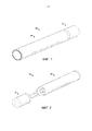
на ФИГ. 1 показан перспективный вид устройства доставки аэрозоля, содержащего картридж и управляющий корпус, причем эти картридж и управляющий корпус соединены между собой согласно примеру варианта осуществления настоящего изобретения; in FIG. 1 is a perspective view of an aerosol delivery device comprising a cartridge and a control housing, the cartridge and control housing being interconnected according to an exemplary embodiment of the present invention;
на ФИГ. 2 показан перспективный вид устройства доставки аэрозоля по ФИГ. 1, в котором картридж и управляющий корпус отделены друг от друга, согласно примеру варианта осуществления настоящего изобретения;in FIG. 2 is a perspective view of the aerosol delivery device of FIG. 1 in which the cartridge and the control housing are separated from each other according to an exemplary embodiment of the present invention;
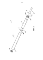
на ФИГ. 3 показан покомпонентный вид управляющего корпуса по ФИГ. 1, в котором передающее устройство связи имеет трубчатую конфигурацию, согласно примеру варианта осуществления настоящего изобретения;in FIG. 3 is an exploded view of the control housing of FIG. 1, in which the transmitting communication device has a tubular configuration according to an example embodiment of the present invention;
на ФИГ. 4 показан вид в сечении управляющего корпуса по ФИГ. 3;in FIG. 4 is a cross-sectional view of the control housing of FIG. 3;
на ФИГ. 5 показан вид в сечении управляющего корпуса по ФИГ. 1, в котором передающее устройство связи имеет спиральную конфигурацию, согласно примеру варианта осуществления настоящего изобретения;in FIG. 5 is a cross-sectional view of the control housing of FIG. 1, in which the transmitting communication device has a helical configuration according to an example embodiment of the present invention;
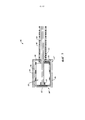
на ФИГ. 6 показан покомпонентный вид картриджа по ФИГ. 1, в котором субстрат проходит внутрь внутреннего отделения, образованного емкостью согласно первому примеру варианта осуществления настоящего изобретения;in FIG. 6 is an exploded view of the cartridge of FIG. 1 in which the substrate extends to the inside of the inner compartment formed by the container according to the first exemplary embodiment of the present invention;
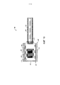
на ФИГ. 7 показан вид в сечении картриджа по ФИГ. 6;in FIG. 7 is a cross-sectional view of the cartridge of FIG. 6;
на ФИГ. 8 показан вид в сечении картриджа по ФИГ. 1, содержащего резервуарный субстрат во внутреннем отделении, образованном емкостью, согласно второму примеру варианта осуществления настоящего изобретения;in FIG. 8 is a cross-sectional view of the cartridge of FIG. 1 containing a reservoir substrate in an inner compartment formed by a container according to a second exemplary embodiment of the present invention;
на ФИГ. 9 показан вид в сечении картриджа по ФИГ. 1, содержащего субстрат, находящийся в контакте с резонансным приемным устройством связи, согласно третьему примеру варианта осуществления настоящего изобретения;in FIG. 9 is a cross-sectional view of the cartridge of FIG. 1 containing a substrate in contact with a resonant communication receiving device according to a third exemplary embodiment of the present invention;
на ФИГ. 10 показан вид в сечении картриджа про ФИГ. 1, содержащего электронный управляющий компонент, согласно четвертому примеру варианта осуществления настоящего изобретения;in FIG. 10 is a cross-sectional view of the cartridge of FIG. 1 containing an electronic control component according to a fourth exemplary embodiment of the present invention;
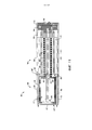
на ФИГ. 11 показан вид в сечении устройства доставки аэрозоля по ФИГ. 1, содержащего картридж по ФИГ. 6 и управляющий корпус по ФИГ. 3, согласно примеру варианта осуществления настоящего изобретения;in FIG. 11 is a cross-sectional view of the aerosol delivery device of FIG. 1 containing the cartridge of FIG. 6 and the control body of FIG. 3 according to an example embodiment of the present invention;
на ФИГ. 12, 13 и 14 показана схема и другие компоненты устройства доставки аэрозоля согласно примеру варианта осуществления;in FIG. 12, 13 and 14 show a schematic diagram and other components of an aerosol delivery device according to an exemplary embodiment;
на ФИГ. 15 схематично показан способ сборки устройства доставки аэрозоля согласно примеру варианта осуществления настоящего изобретения; иin FIG. 15 is a schematic diagram of a method for assembling an aerosol delivery device according to an exemplary embodiment of the present invention; and
на ФИГ. 16 схематично показан способ аэрозолизации согласно примеру варианта осуществления настоящего изобретения.in FIG. 16 is a schematic diagram of an aerosolization method according to an exemplary embodiment of the present invention.
ОСУЩЕСТВЛЕНИЕ ИЗОБРЕТЕНИЯCARRYING OUT THE INVENTION
Настоящее изобретение будет далее описано более полно со ссылками на примеры вариантов его осуществления. Эти примеры вариантов осуществления описаны таким образом, чтобы настоящее описание было исчерпывающим и полным и полностью доносило объем настоящего изобретения до специалистов в данной области техники. В реальности настоящее изобретение может быть осуществлено во многих различных формах, и оно не должно рассматриваться как ограниченное вариантами осуществления, изложенными в настоящем описании; эти варианты осуществления приведены лишь с тем, чтобы настоящее описание удовлетворяло требованиям применимого законодательства. Используемые в настоящем описании и приложенной формуле изобретения формы единственного числа включают формы множественного числа, если контекст однозначно не указывает на иное. Кроме того, хотя в настоящем описании возможны ссылки на количественные показатели, значения, геометрические отношения и т.п., любое одно или более, если не всё, из вышеперечисленного может являться точным или приближенным для учета допустимых вариаций, которые могут иметь место, например тех вариаций, которые обусловлены технологическими допусками и т.п., если не указано иное.The present invention will be further described more fully with reference to exemplary embodiments. These exemplary embodiments are described so that the present description is exhaustive and complete and will fully convey the scope of the present invention to those skilled in the art. In reality, the present invention can be implemented in many different forms, and it should not be construed as limited to the options for implementation set forth in the present description; these embodiments are provided only to ensure that the present description meets the requirements of applicable law. As used in the present description and the appended claims, the singular includes the plural, unless the context clearly dictates otherwise. In addition, while references may be made to quantities, values, geometric relationships, and the like, any one or more, if not all, of the above may be accurate or approximate to account for allowable variations that may occur, for example those variations that are due to technological tolerances, etc., unless otherwise indicated.
Как описано далее, примеры вариантов осуществления настоящего изобретения относятся к устройствам доставки аэрозоля. Устройства доставки аэрозоля согласно настоящему изобретению используют электрическую энергию для нагрева материала (предпочтительно, без горения материала в сколь-нибудь значительной степени) для образования вдыхаемого вещества, и компоненты таких систем имеют форму изделий, наиболее предпочтительно достаточно компактных для того, чтобы они рассматривались как устройства, удерживаемые в руке. Иначе говоря, использование компонентов предпочтительных устройств доставки аэрозоля не приводит к образованию дыма, как это имеет место в случае образования аэрозоля преимущественно из побочных продуктов горения или пиролиза табака; вместо этого использование предпочтительных систем приводит к образованию пара в результате улетучивания или испарения определенных компонентов, включенных в систему. В некоторых примерах вариантов осуществления компоненты устройств доставки аэрозоля могут быть определены как электронные сигареты; эти электронные сигареты, наиболее предпочтительно, содержат табак и/или производные компоненты табака и, следовательно, они осуществляют доставку производных компонентов табака в форме аэрозоля.As described below, exemplary embodiments of the present invention relate to aerosol delivery devices. Aerosol delivery devices of the present invention use electrical energy to heat a material (preferably without burning the material to any significant extent) to form an inhaled substance, and the components of such systems are in the form of articles, most preferably sufficiently compact to be considered devices. held in hand. In other words, the use of the components of the preferred aerosol delivery devices does not generate smoke, as is the case for aerosol formation predominantly from the by-products of combustion or pyrolysis of tobacco; instead, the use of preferred systems results in the generation of steam as a result of volatilization or vaporization of certain components included in the system. In some exemplary embodiments, components of aerosol delivery devices may be referred to as electronic cigarettes; these electronic cigarettes most preferably contain tobacco and / or derived tobacco components and therefore deliver the derived tobacco components in aerosol form.
Генерирующие аэрозоль части некоторых предпочтительных устройств доставки аэрозоля способны обеспечивать многие из ощущений (например, ритуалы вдыхания и выдыхания, типы вкусов и ароматов, органолептические эффекты, физические ощущения, ритуалы использования, визуальные признаки, например такие, которые создаются видимым аэрозолем, и т.п.), создаваемых при курении сигарет, сигар и трубок, используемых путем поджигания и горения табака (и, следовательно, вдыхания табачного дыма), без сколь-нибудь существенного горения каких-либо их компонентов. Например, пользователь генерирующей аэрозоль части согласно настоящему изобретению может удерживать и использовать эту часть подобно тому, как курильщик использует курительное изделие традиционного типа, осуществлять затяжки на одном конце этой части для вдыхания аэрозоля, создаваемого данной частью, осуществлять затяжки через выбранные промежутки времени и т.п.The aerosol generating portions of some preferred aerosol delivery devices are capable of providing many of the sensations (e.g., inhalation and exhalation rituals, types of tastes and aromas, organoleptic effects, physical sensations, use rituals, visual cues such as those generated by a visible aerosol, etc.) .) created by smoking cigarettes, cigars and pipes used by igniting and burning tobacco (and, therefore, inhaling tobacco smoke), without any significant combustion of any of their components. For example, the user of the aerosol generating part according to the present invention can hold and use the part in the same way as a smoker uses a conventional type of smoking article, puffs at one end of the part to inhale the aerosol generated by the part, puffs at selected intervals, etc. P.
Хотя указанные системы в целом описаны в данном документе в отношении вариантов осуществления, связанных с устройствами доставки аэрозоля, такими как т.н. «электронные сигареты», следует понимать, что механизмы, компоненты, признаки и способы могут быть осуществлены во многих различных формах и связаны с множеством изделий. Например, приведенное в данном документе описание может применяться в сочетании с вариантами осуществления традиционных курительных изделий (например, сигарет, сигар, трубок и т.п.), сигарет, нагреваемых без горения, и соответствующих упаковок для любого из продуктов, раскрытых в данном документе. Соответственно, следует понимать, что описание механизмов, компонентов, признаков и способов, раскрытых в данном документе, приведено в отношении вариантов осуществления, относящихся к устройствам доставки аэрозоля, лишь в качестве примера, и их осуществление и использование возможно в виде различных других продуктов и способов.Although these systems are generally described herein with respect to embodiments associated with aerosol delivery devices such as the so-called. "Electronic cigarettes", it should be understood that the mechanisms, components, features and methods can be implemented in many different forms and associated with a variety of products. For example, the description provided herein may be used in conjunction with embodiments of conventional smoking articles (e.g., cigarettes, cigars, pipes, etc.), non-combustible cigarettes, and associated packaging for any of the products disclosed herein. ... Accordingly, it should be understood that the description of the mechanisms, components, features and methods disclosed herein is given with respect to embodiments related to aerosol delivery devices, by way of example only, and their implementation and use is possible in the form of various other products and methods. ...
Устройства доставки аэрозоля согласно настоящему изобретению могут также быть определены как парообразующие изделия или изделия для доставки медицинских препаратов. Следовательно, подобные изделия или устройства могут быть выполнены таким образом, чтобы обеспечивать одно или более веществ (например, ароматизаторов и/или фармацевтически активных ингредиентов) в пригодной для вдыхания форме или состоянии. Например, пригодные для вдыхания вещества могут находиться по существу в форме пара (т.е. вещества, которое находится в газовой фазе при температуре ниже его критической точки). В качестве альтернативы, пригодные для вдыхания вещества могут находиться в форме аэрозоля (т.е. взвеси тонкодисперсных твердых частиц или жидких капель в газе). Для простоты, термин «аэрозоль» используется в настоящем описании в смысле, включающем в себя пары, газы и аэрозоли той формы или типа, которые пригодны для их вдыхания человеком, независимо от того, являются ли они видимыми или нет, и от того, может ли их форма считаться дымообразной или нет.Aerosol delivery devices of the present invention can also be defined as vaporous or medical drug delivery devices. Therefore, such articles or devices can be designed to provide one or more substances (eg, flavors and / or pharmaceutically active ingredients) in a respirable form or state. For example, respirable substances can be substantially in the form of vapor (i.e., a substance that is in the gaseous phase at a temperature below its critical point). Alternatively, respirable substances can be in the form of an aerosol (i.e., a suspension of fine solids or liquid droplets in a gas). For simplicity, the term "aerosol" is used herein to include vapors, gases and aerosols of the form or type suitable for human inhalation, whether visible or not, and whether whether their shape is considered smoky or not.
Устройства доставки аэрозоля согласно настоящему изобретению при их использовании могут подвергаться многим из физических действий, осуществляемых пользователем при использовании курительных изделий традиционного типа (например, сигарет, сигар или трубок, которые используются путем поджигания табака и вдыхания табачного дыма). Например, пользователь устройства доставки аэрозоля согласно настоящему изобретению может держать данное изделие подобно тому, как держат курительное изделие традиционного типа, осуществлять затяжки на одном конце данного изделия для вдыхания аэрозоля, создаваемого данным изделием, осуществлять затяжки через выбранные промежутки времени и т.д.The aerosol delivery devices of the present invention, when used, may undergo many of the physical actions performed by the user when using conventional smoking articles (eg, cigarettes, cigars, or pipes that are used by lighting tobacco and inhaling tobacco smoke). For example, a user of the aerosol delivery device of the present invention can hold the article in a manner similar to holding a conventional smoking article, puff at one end of the article to inhale the aerosol generated by the article, puff at selected intervals, etc.
Устройства доставки аэрозоля согласно настоящему изобретению обычно содержат ряд компонентов, размещенных внутри внешнего корпуса или оболочки, которая может именоваться кожухом. Общая конструкция внешнего корпуса или оболочки может варьироваться, и формат или конфигурация внешнего корпуса, которые могут определять общий размер и форму устройства доставки аэрозоля, также могут варьироваться. Обычно удлиненный корпус, сходный по форме с сигаретой или сигарой, может быть выполнен в виде одного монолитного кожуха, или удлиненный кожух может быть выполнен из двух или более разделяемых частей. Например, устройство доставки аэрозоля может содержать удлиненную оболочку или корпус, которые могут иметь по существу трубчатую форму, и таким образом оно может быть похоже по форме на обычную сигарету или сигару. В одном примере все из компонентов устройства доставки аэрозоля заключены внутри одного кожуха. В качестве альтернативы, устройство доставки аэрозоля может содержать два или более кожухов, которые соединены и имеют возможность разделения. Например, устройство доставки аэрозоля может иметь на одном конце управляющий корпус, содержащий кожух, заключающий в себе один или более многоразовых компонентов (например, аккумулятор, такой как перезаряжаемая батарея и/или перезаряжаемый конденсатор большой емкости, различные электронные компоненты для управления работой изделия), а к другому концу имеет возможность разъемного присоединения внешний корпус или оболочка, заключающая в себе одноразовую часть (например, одноразовый картридж, заключающий в себе ароматизатор). Более специфические форматы, конфигурации и компоновки компонентов внутри модуля с кожухом монолитного типа или внутри модуля с кожухом составного разделяемого типа должны стать понятны в свете дополнительного описания, приведенного в настоящем документе. Кроме того, различные конструкции и компоновки компонентов устройств доставки аэрозоля могут стать понятны при рассмотрении имеющихся в продаже электронных устройств доставки аэрозоля.Aerosol delivery devices of the present invention typically comprise a number of components housed within an outer casing or shell, which may be referred to as a casing. The overall design of the outer housing or shell can vary, and the format or configuration of the outer housing, which can determine the overall size and shape of the aerosol delivery device, can also vary. Typically, an elongated body, similar in shape to a cigarette or cigar, can be formed as a single monolithic casing, or the elongated casing can be made of two or more separable parts. For example, the aerosol delivery device may comprise an elongated shell or housing that may be substantially tubular in shape and thus similar in shape to a conventional cigarette or cigar. In one example, all of the components of the aerosol delivery device are contained within a single housing. Alternatively, the aerosol delivery device may comprise two or more housings that are connected and separable. For example, an aerosol delivery device may have at one end a control housing containing a housing enclosing one or more reusable components (e.g., a battery such as a rechargeable battery and / or a high capacity rechargeable capacitor, various electronic components for controlling the operation of the product), and to the other end, an outer casing or shell containing a disposable part (eg, a disposable cartridge containing a fragrance) can be detachably attached. More specific formats, configurations and arrangements of components within a monolithic-type shroud module or within a multiple-type shroud module are to be understood in light of the additional description provided herein. In addition, various designs and component arrangements of aerosol delivery devices can be understood by considering commercially available electronic aerosol delivery devices.
Устройства доставки аэрозоля согласно настоящему изобретению наиболее предпочтительно содержат некоторую комбинацию из следующего: источника питания (т.е. источника электрической мощности), по меньшей мере одного управляющего компонента (например, средства для активации, управления, регулирования и прерывания подачи мощности для генерирования аэрозоля, например, путем управления подачей электрического тока от источника питания на другие компоненты изделия - например, микропроцессор, выполненный отдельно или как часть микроконтроллера), нагревателя или элемента для генерирования тепла (например, электрорезистивного нагревательного элемента или другого компонента, который, отдельно или в сочетании с одним или более дополнительными элементами, может в целом именоваться «атомайзером»), композиции предшественника аэрозоля (например, в общем случае, жидкости, способной образовывать аэрозоль при передаче на нее достаточного количества тепла, такой как вещества, в целом именуемые «курительным соком», «е-жидкостью» и «е-соком») и мундштучной концевой области или концевой части для обеспечения возможности осуществления затяжки на устройстве доставки аэрозоля с целью вдыхания аэрозоля (например, с каналом воздушного потока, проходящим через изделие таким образом, чтобы была обеспечена возможность вытягивания из него аэрозоля при затяжке).Aerosol delivery devices according to the present invention most preferably comprise some combination of the following: a power supply (i.e., an electrical power source), at least one control component (e.g., means for activating, controlling, regulating and interrupting the power supply to generate an aerosol, for example, by controlling the supply of electrical current from a power source to other components of the product - for example, a microprocessor, made separately or as part of a microcontroller), a heater, or an element for generating heat (for example, an electroresistive heating element or other component that, alone or in combination with one or more additional elements, may be generally referred to as an "atomizer"), an aerosol precursor composition (e.g., generally, a liquid capable of forming an aerosol when sufficient heat is transferred to it, such as substances generally referred to as a "smokable juice ”,“ e-liquid ”and“ e-juice ”) and a mouth end region or end portion to allow a puff to be applied to the aerosol delivery device to inhale the aerosol (for example, with an air flow channel through the product so that it was possible to draw aerosol out of it when tightening).
Компоновка компонентов внутри устройства доставки аэрозоля согласно настоящему изобретению может варьироваться. В конкретных вариантах осуществления композиция предшественника аэрозоля может быть размещена вблизи того конца устройства доставки аэрозоля, который может быть выполнен с возможностью размещения вблизи рта пользователя, с тем, чтобы максимизировать доставку аэрозоля пользователю. Тем не менее, не исключены и другие конфигурации. В целом, нагревательный элемент может быть размещен достаточно близко к композиции предшественника аэрозоля с тем, чтобы под действием тепла от нагревательного элемента была обеспечена возможность испарения композиции предшественника аэрозоля (а также одного или более из следующего: ароматизаторов, медицинских препаратов и т.п., которые могут аналогичным образом обеспечиваться для доставки пользователю) и образования аэрозоля для доставки пользователю. При нагреве композиции предшественника аэрозоля с помощью нагревательного элемента, происходит образование, выделение или генерирование аэрозоля в физической форме, пригодной для вдыхания потребителем. Следует отметить, что вышеуказанные термины подразумевают их использование взаимозаменяемым образом, так что термины «выделяться», «выделяющийся», «выделяется» или «выделяемый» включают в себя термины «образовываться» или «генерироваться», «образующийся» или «генерирующийся», «образует» или «генерирует» или «образуемый» или «генерируемый». В конкретном плане, вдыхаемое вещество выделяется в форме пара или аэрозоля или их смеси, причем такие термины также используются взаимозаменяемым образом в настоящем описании, если не указано иное.The arrangement of the components within the aerosol delivery device of the present invention can vary. In certain embodiments, the aerosol precursor composition may be positioned proximate to an end of the aerosol delivery device that may be configured to be positioned near the user's mouth so as to maximize delivery of the aerosol to the user. However, other configurations are not excluded. In general, the heating element can be positioned close enough to the aerosol precursor composition so that heat from the heating element allows the aerosol precursor composition (as well as one or more of the following: fragrances, medicines, etc., which can similarly be provided for delivery to a user) and form an aerosol for delivery to a user. When the aerosol precursor composition is heated with a heating element, an aerosol is formed, emitted or generated in a physical form suitable for inhalation by the consumer. It should be noted that the above terms are intended to be used interchangeably, so that the terms "stand out", "stand out", "stand out" or "stand out" include the terms "formed" or "generated", "generated" or "generated", "Generates" or "generates" or "generated" or "generated". Specifically, the respirable substance is emitted in the form of vapor or aerosol, or mixtures thereof, and such terms are also used interchangeably throughout this specification unless otherwise indicated.
Как было отмечено выше, устройство доставки аэрозоля может содержать батарею или другой электрический источник питания для подачи тока, достаточного для обеспечения различных функциональных возможностей, на устройство доставки аэрозоля, в частности для питания нагревателя, для питания систем управления, для питания индикаторов и т.п. Возможны различные варианты осуществления источника питания. Предпочтительно, источник питания способен обеспечивать мощность, достаточную для быстрого нагрева нагревательного элемента для обеспечения образования аэрозоля, и обеспечивать питание устройства доставки аэрозоля на всем протяжении его использовании в течение требуемого периода времени. Источник питания предпочтительно выполнен по размеру с возможностью удобной вставки внутрь устройства доставки аэрозоля с тем, чтобы была обеспечена возможность легкого манипулирования устройством доставки аэрозоля. Кроме того, предпочтительный источник питания имеет достаточно малый вес, чтобы не ухудшать желаемые ощущения от курения.As noted above, the aerosol delivery device may contain a battery or other electrical power source for supplying current sufficient to provide various functionality to the aerosol delivery device, in particular to power a heater, to power control systems, to power indicators, etc. ... Various embodiments of the power supply are possible. Preferably, the power supply is capable of providing sufficient power to rapidly heat the heating element to generate aerosol and provide power to the aerosol delivery device throughout its use for a desired period of time. The power supply is preferably sized to fit comfortably within the aerosol delivery device so that the aerosol delivery device can be easily manipulated. In addition, the preferred food source is light enough not to impair the desired smoking experience.
Более конкретные форматы, конфигурации и компоновки компонентов внутри устройства доставки аэрозоля согласно настоящему изобретению станут понятны в свете дальнейшего описания, приведенного в данном документе. В дополнение, выбор различных компонентов устройства доставки аэрозоля может стать понятен при рассмотрении имеющихся в продаже устройств доставки аэрозоля. Кроме того, компоновка компонентов внутри устройства доставки аэрозоля также может стать понятна при рассмотрении имеющихся в продаже электронных устройств доставки аэрозоля.More specific formats, configurations and arrangements of components within an aerosol delivery device according to the present invention will become apparent in light of the further description provided herein. In addition, the selection of the various components of the aerosol delivery device can be understood by considering commercially available aerosol delivery devices. In addition, the arrangement of the components within the aerosol delivery device can also be understood by considering commercially available electronic aerosol delivery devices.
Как описано далее, настоящее изобретение относится к устройствам доставки аэрозоля. Устройства доставки аэрозоля могут быть выполнены с возможностью нагрева композиции предшественника аэрозоля для образования аэрозоля. В некоторых вариантах осуществления устройства доставки аэрозоля могут представлять собой нагреваемые без горения устройства, выполненные с возможностью нагрева твердой композиции предшественника аэрозоля (экструдированного табачного стержня) или полутвердой композиции предшественника аэрозоля (например, табачной пасты с добавлением глицерина). В еще одном варианте осуществления, устройства доставки аэрозоля могут быть выполнены с возможностью нагрева и образования аэрозоля из текучей композиции предшественника аэрозоля (например, жидкой композиции предшественника аэрозоля). Такие устройства доставки аэрозоля могут включать т.н. электронные сигареты.As described below, the present invention relates to aerosol delivery devices. Aerosol delivery devices can be configured to heat the aerosol precursor composition to form an aerosol. In some embodiments, the aerosol delivery devices can be non-combustible heated devices configured to heat a solid aerosol precursor composition (extruded tobacco rod) or a semi-solid aerosol precursor composition (eg, glycerin-added tobacco paste). In yet another embodiment, the aerosol delivery devices can be configured to heat and form an aerosol from a fluid aerosol precursor composition (eg, a liquid aerosol precursor composition). Such aerosol delivery devices may include the so-called. e-Sigs.
Независимо от типа нагреваемой композиции предшественника аэрозоля, устройства доставки аэрозоля могут содержать нагревательный элемент, выполненный с возможностью нагрева композиции предшественника аэрозоля. В некоторых вариантах осуществления нагревательный элемент может представлять собой резистивный нагревательный элемент. Резистивные нагревательные элементы могут быть выполнены с возможностью выработки тепла при пропускании через них электрического тока. Такие нагревательные элементы часто содержат металлический материал и выполнены с возможностью выработки тепла за счет электрического сопротивления, создаваемого при протекании через них электрического тока. Такие резистивные нагревательные элементы могут быть размещены вблизи композиции предшественника аэрозоля. Например, в некоторых вариантах осуществления резистивные нагревательные элементы могут содержать одну или более катушек провода, намотанных вокруг элемента переноса жидкости (например, фитиля, который может содержать пористую керамику, углерод, ацетилцеллюлозу, полиэтилентерефталат, стекловолокно или пористое спеченное стекло), выполненного с возможностью втягивания через него композиции предшественника аэрозоля. В качестве альтернативы, нагревательный элемент может быть размещен в контакте с твердой или полутвердой композицией предшественника аэрозоля. Такие конфигурации способны нагревать композицию предшественника аэрозоля для образования аэрозоля.Regardless of the type of aerosol precursor composition being heated, the aerosol delivery devices may comprise a heating element configured to heat the aerosol precursor composition. In some embodiments, the heating element may be a resistive heating element. Resistive heating elements can be configured to generate heat by passing an electric current through them. Such heating elements often contain a metallic material and are configured to generate heat by the electrical resistance created by the flow of electrical current through them. Such resistive heating elements can be placed in the vicinity of the aerosol precursor composition. For example, in some embodiments, resistive heating elements may comprise one or more coils of wire wound around a fluid transfer member (e.g., a wick that may contain porous ceramic, carbon, cellulose acetate, polyethylene terephthalate, glass fiber, or porous sintered glass) retractable through it aerosol precursor compositions. Alternatively, the heating element can be placed in contact with a solid or semi-solid aerosol precursor composition. Such configurations are capable of heating the aerosol precursor composition to form the aerosol.
В некоторых вариантах осуществления, устройства доставки аэрозоля могут содержать управляющий корпус и картридж. Управляющий корпус может быть многоразовым, в то время как картридж может быть выполнен в расчете на ограниченное количество использований и/или он может быть выполнен одноразовым. Картридж может содержать композицию предшественника аэрозоля. С целью нагрева композиции предшественника аэрозоля, в картридже также может быть размещен нагревательный элемент. Управляющий корпус может содержать источник питания, который может быть перезаряжаемым или сменным, и таким образом обеспечивается возможность многократного использования управляющего корпуса с множеством картриджей.In some embodiments, aerosol delivery devices may include a control housing and a cartridge. The control housing can be reusable, while the cartridge can be made for a limited number of uses and / or it can be made disposable. The cartridge may contain an aerosol precursor composition. For the purpose of heating the aerosol precursor composition, a heating element may also be disposed in the cartridge. The control housing may contain a power supply that can be rechargeable or replaceable, and thus allows the control housing to be reusable with multiple cartridges.
Хотя вышеописанные устройства доставки аэрозоля могут применяться для нагрева композиции предшественника аэрозоля с образованием аэрозоля, такие конфигурации могут иметь один или более недостатков. Это связано с тем, что резистивные нагревательные элементы могут содержать провод, образующий одну или более катушек, которые контактируют с композицией предшественника аэрозоля. Например, как отмечено выше, катушки могут быть намотаны вокруг элемента переноса жидкости (например, фитиля) для нагрева и аэрозолизации композиции предшественника аэрозоля, подаваемой к нагревательнному элементу через элемент переноса жидкости. Однако, вследствие того, что указанные катушки имеют сравнительно малую площадь поверхности, некоторая часть композиции предшественника аэрозоля может нагреваться до избыточно высокой температуры во время аэрозолизации, что приводит к непроизводительному расходу энергии. В качестве альтернативы или дополнительно, некоторая часть композиции предшественника аэрозоля, которая не находится в контакте с катушками нагревательного элемента, может нагреваться до температуры, недостаточной для аэрозолизации. Соответственно, может иметь место недостаточная аэрозолизация, либо возможны непроизводительные потери энергии при аэрозолизации.While the above aerosol delivery devices can be used to heat an aerosol precursor composition to form an aerosol, such configurations can have one or more disadvantages. This is because the resistance heating elements may comprise a wire forming one or more coils that contact the aerosol precursor composition. For example, as noted above, coils can be wound around a fluid transfer member (eg, a wick) to heat and aerosolize the aerosol precursor composition supplied to the heating member through the fluid transfer member. However, due to the relatively small surface area of these coils, some of the aerosol precursor composition may heat up to an excessively high temperature during aerosolization, resulting in wasted energy. Alternatively or additionally, some of the aerosol precursor composition that is not in contact with the heating element coils may be heated to a temperature insufficient for aerosolization. Accordingly, insufficient aerosolization may occur, or unproductive energy losses during aerosolization may occur.
Кроме того, как отмечено выше, резистивные нагревательные элементы вырабатывают тепло при пропускании через них электрического тока. Соответственно, в результате размещения нагревательного элемента в контакте с композицией предшественника аэрозоля, может происходить обугливание композиции предшественника аэрозоля. Такое обугливание может происходить под действием тепла, вырабатываемого нагревательным элементом, и/или под действием электрического тока, протекающего через композицию предшественника аэрозоля на нагревательном элементе. Обугливание может приводить к скоплению материала на нагревательном элементе. Такое скопление материала может негативно повлиять на вкус и аромат аэрозоля, выделяющегося из композиции предшественника аэрозоля.In addition, as noted above, resistive heating elements generate heat when an electric current is passed through them. Accordingly, as a result of placing the heating element in contact with the aerosol precursor composition, carbonization of the aerosol precursor composition may occur. Such charring can occur by heat generated by the heating element and / or by electric current flowing through the aerosol precursor composition on the heating element. Carbonization can lead to accumulation of material on the heating element. Such accumulation of material can adversely affect the taste and aroma of the aerosol released from the aerosol precursor composition.
Как дополнительно описано выше, устройства доставки аэрозоля могут содержать управляющий корпус, содержащий источник питания и картридж, содержащий резистивный нагревательный элемент и композицию предшественника аэрозоля. С целью подачи электрического тока на резистивный нагревательный элемент, управляющий корпус и картридж могут содержать электрические соединители, выполненные с возможностью соединения между собой при соединении картриджа с управляющим корпусом. Однако вследствие использования этих электрических соединителей возможно дополнительное усложнение и удорожание таких устройств доставки аэрозоля. В дополнение, в вариантах осуществления устройств доставки аэрозоля, содержащих текучую композицию предшественника аэрозоля, может происходить ее утечка на клеммах или других соединителях внутри картриджа.As further described above, aerosol delivery devices may comprise a control housing containing a power source and a cartridge containing a resistance heating element and an aerosol precursor composition. For the purpose of supplying electric current to the resistive heating element, the control housing and the cartridge may comprise electrical connectors adapted to be connected to each other when the cartridge is connected to the control housing. However, due to the use of these electrical connectors, such aerosol delivery devices can be further complicated and expensive. In addition, embodiments of aerosol delivery devices containing a pourable aerosol precursor composition may leak at terminals or other connectors within the cartridge.
Таким образом, варианты осуществления настоящего изобретения направлены на создание устройства доставки аэрозоля, которые обеспечивают возможность устранения некоторых или всех проблем, отмеченных выше. В этой связи, на ФИГ. 1 показано устройство 100 доставки аэрозоля согласно примеру осуществления настоящего изобретения. Устройство доставки аэрозоля может содержать картридж 102 и управляющий корпус 104. Картридж и управляющий корпус могут быть неразъемно или разъемно сопряжены в функциональном отношении. В этой связи, на ФИГ. 1 показано устройство доставки аэрозоля в соединенной конфигурации, а на ФИГ. 2 показано устройство доставки аэрозоля в разъединенной конфигурации. Для соединения картриджа с управляющим корпусом могут использоваться различные механизмы, обеспечивающие резьбовое соединение, прессовую посадку, посадку с натягом, магнитное соединение и т.п. Устройство доставки аэрозоля в некоторых вариантах осуществления может иметь по существу стержнеобразную, по существу трубчатую или по существу цилиндрическую форму при нахождении картриджа и управляющего корпуса в соединенное конфигурации.Thus, embodiments of the present invention are directed to aerosol delivery devices that can overcome some or all of the problems noted above. In this regard, in FIG. 1 shows an
В конкретных вариантах осуществления картридж 102 и/или управляющий корпус 104 могут упоминаться как одноразовые или как многоразовые. Например, управляющий корпус может иметь сменную батарею или перезаряжаемую батарею, твердотельную батарею, тонкопленочную твердотельную батарею, перезаряжаемый конденсатор большой емкости и т.п., и таким образом он может сочетаться с любым типом технологии перезарядки, включая соединение с настенным зарядным устройством, соединение с автомобильным зарядным устройством (например, гнездом прикуривателя) и соединение с компьютером, например, посредством кабеля или соединителя универсальной последовательной шины (universal serial bus, USB) (например, USB 2.0, 3.0, 3.1, USB Type-C), соединение с фотоэлектрическим элементом (иногда именуемым солнечным фотоэлементом) или солнечной батареей из солнечных фотоэлементов, или с беспроводным зарядным устройством на основе радиочастоты. Кроме того, в некоторых вариантах осуществления картридж 102 может представлять собой одноразовый картридж, как раскрыто в патенте США №8,910,639, авторы Chang и др., который полностью включен в настоящую заявку посредством ссылки.In specific embodiments,
На ФИГ. 3 показан покомпонентный вид управляющего корпуса 104 для устройства 100 доставки аэрозоля согласно примеру варианта осуществления настоящего изобретения. Как показано на фигуре, управляющий корпус может содержать передающее устройство 302 связи, внешний корпус 304, датчик 306 потока (например, датчик затяжки или датчик давления), управляющий компонент 308 (например, микропроцессор, предусмотренный отдельно или в качестве части микроконтроллера), разделитель 310, источник 312 питания (например, батарею, которая может быть перезаряжаемой, и/или перезаряжаемый конденсатор большой емкости), схемную плату с индикатором 314 (например, светодиодом), соединительную схему 316 и концевой колпачок 318. Примеры источников питания описаны в патенте США №9,484,155, авторы Peckerar и др., и в патентной заявке США сер. № 14/918,926, авторы Sur и др., дата подачи 21 октября 2015 г., которые полностью включены в настоящую заявку посредством ссылки.FIG. 3 is an exploded view of a
Что касается датчика 306 потока, репрезентативных компонентов для регулирования тока и других компонентов для управления током, в том числе различных микроконтроллеров, датчиков и переключателей для устройств доставки аэрозоля, то они описаны в патенте США №4,735,217, авторы Gerth и др., патентах США №№4,922,901, 4,947,874, и 4,947,875, авторы во всех случаях Brooks и др., патенте США №5,372,148, авторы McCafferty и др., патенте США №6,040,560, авторы Fleischhauer и др., патенте США №7,040,314, авторы Nguyen и др., и патенте США №8,205,622, автор Pan, содержание всех из которых полностью включено в настоящую заявку посредством ссылки. Сделана также ссылка на схемы управления, описанные в патенте США №9,423,152, авторы Ampolini и др., содержание которого полностью включено в настоящую заявку посредством ссылки.
В одном варианте осуществления индикатор 314 может содержать один или более светодиодов, светодиодов на квантовых точках и т.п. Индикатор может иметь связь с управляющим компонентом 308 через соединительную схему 316 и зажигаться, например, в течение осуществляемой пользователем затяжки на картридже (например, сигарете 102 по фиг. 2), соединенном с управляющим корпусом 104, при обнаружении указанной затяжки с помощью датчика 306 потока. Концевой колпачок 318 может быть выполнен таким образом, чтобы можно было видеть свет, излучаемый индикатором под этим колпачком. Соответственно, индикатор может зажигаться в течение использования устройства 100 доставки аэрозоля для имитации зажженного конца курительного изделия. Тем не менее, в других вариантах осуществления индикатор может быть обеспечен в изменяемом количестве, он может принимать разные формы и даже представлять собой отверстие во внешнем корпусе (например, для эмиссии звука при наличии таких индикаторов).In one embodiment,
В устройстве доставки аэрозоля согласно настоящему изобретению могут также использоваться и другие компоненты. Например, в патенте США №5,154,192, авторы Sprinkel и др., раскрыты индикаторы для курительных изделий; в патенте США №5,261,424, автор Sprinkel, Jr., раскрыты пьезоэлектрические датчики, которые могут быть связаны с мундштучным концом устройства для обнаружения активности губ пользователя, связанной с осуществлением затяжки, и последующего запуска нагрева нагревательного устройства; в патенте США №5,372,148, авторы McCafferty и др., раскрыт датчик затяжки для управления подачей энергии на группу нагревательных нагрузок в соответствии с падением давления на мундштуке; в патенте США №5,967,148, авторы Harris и др., раскрыты приемные гнезда в курительном устройстве, содержащие идентификатор, который обнаруживает неоднородность коэффициента пропускания вставленного компонента по инфракрасному излучению, и контроллер, который исполняет программу обнаружения, когда указанный компонент вставлен внутрь приемного гнезда; в патенте США №6,040,560, авторы Fleischhauer и др., описан определенный исполняемый цикл питания с множеством разных фаз; в патенте США №5,934,289, авторы Watkins и др., раскрыты фотонно-оптронные компоненты; в патенте США №5,954,979, авторы Counts и др., раскрыты средства для изменения сопротивления затяжке через курительное устройство; в патенте США №6,803,545, авторы Blake и др., раскрыты конкретные конфигурации батареи для использования в курительных устройствах; в патенте США №7,293,565, авторы Griffen и др., раскрыты различные зарядные системы для использования с курительными устройствами; в патенте США №8,402,976, авторы Fernando и др., раскрыты компьютерные интерфейсные средства для курительных устройств, облегчающие зарядку и обеспечивающие возможность компьютерного управления устройством; в патенте США №8,689,804, авторы Fernando и др., раскрыты системы идентификации для курительных устройств; и в опубликованной патентной заявке PCT № WO 2010/003480, автор Flick, раскрыта система контроля потока текучей среды, реагирующая на осуществление затяжки в генерирующей аэрозоль системе; все из вышеперечисленных патентов и заявок полностью включены в настоящую заявку посредством ссылки.Other components may also be used in the aerosol delivery device of the present invention. For example, US Pat. No. 5,154,192 to Sprinkel et al. Discloses indicators for smoking articles; US Pat. No. 5,261,424 to Sprinkel, Jr. discloses piezoelectric sensors that can be coupled to the mouth end of the device to detect puff activity of the user's lips and then initiate heating of the heater; US Pat. No. 5,372,148 to McCafferty et al. discloses a tightening sensor for controlling the supply of energy to a group of heating loads in accordance with a pressure drop across a mouthpiece; US Pat. No. 5,967,148 to Harris et al. discloses receptacles in a smoking device comprising an identifier that detects infrared transmittance irregularities of an inserted component and a controller that executes a detection program when said component is inserted inside the receptacle; US Pat. No. 6,040,560 to Fleischhauer et al. describes a specific executable power cycle with many different phases; US Pat. No. 5,934,289 to Watkins et al. discloses photonic-optocoupler components; US Pat. No. 5,954,979 to Counts et al. discloses means for altering the drag resistance through a smoking device; US Pat. No. 6,803,545 to Blake et al. discloses specific battery configurations for use in smoking devices; US Pat. No. 7,293,565 to Griffen et al. discloses various charging systems for use with smoking devices; Fernando et al., US Pat. No. 8,402,976, discloses computer interface means for smoking devices that facilitate charging and enable computer control of the device; Fernando et al., US Pat. No. 8,689,804 discloses identification systems for smoking devices; and PCT Published Patent Application No. WO 2010/003480 to Flick discloses a fluid flow control system responsive to puffing in an aerosol generating system; all of the above patents and applications are hereby incorporated by reference in their entirety.
Дополнительные примеры раскрытия компонентов, относящихся к электронным изделиям для доставки аэрозоля, и материалов или компонентов, которые могут использоваться в настоящем изделии, включают: патент США №4,735,217, авторы Gerth и др.; патент США №5,249,586 авторы Morgan и др.; патент США №5,666,977, авторы Higgins и др.; патент США №6,053,176, авторы Adams и др.; патент США №6,164,287, автор White; патент США №6,196,218, автор Voges; патент США №6,810,883, авторы Felter и др.; патент США №6,854,461, автор Nichols; патент США №7,832,410, автор Hon; патент США №7,513,253, автор Kobayashi; патент США №7,896,006, автор Hamano; патент США №6,772,756, автор Shayan; патенты США №8,156,944 и №8,375,957, автор Hon; патент США №8,794,231, авторы Thorens и др.; патент США №8,851,083, авторы Oglesby и др.; патенты США №8,915,254 и №8,925,555, авторы Monsees и др.; патент США №9,220,302, авторы DePiano и др.; опубликованные патентные заявки США №№2006/0196518 и 2009/0188490, автор Hon; опубликованную патентную заявку США № 2010/0024834, автор Oglesby и др.; опубликованную патентную заявку США №2010/0307518, автор Wang; опубликованную патентную заявку PCT № WO 2010/091593, автор Hon; и опубликованную патентную заявку PCT № WO 2013/089551, автор Foo, все из которых полностью включены в настоящую заявку посредством ссылки. Кроме того, в опубликованной патентной заявке США сер. №14/881,392, авторы Worm и др., дата подачи 13 октября 2015 г., раскрыты капсулы, которые могут быть включены в устройства доставки аэрозоля, и конфигурации в виде брелока для устройств доставки аэрозоля; данная заявка полностью включена в настоящую заявку посредством ссылки. Различные материалы, раскрытые в вышеперечисленных документах, могут быть включены в устройства согласно настоящему изобретению в различных вариантах осуществления, и все из вышеперечисленных документов полностью включены в настоящую заявку посредством ссылки.Additional examples of the disclosure of components related to electronic products for aerosol delivery, and materials or components that can be used in the present product include: US patent No. 4,735,217 by Gerth et al .; US Patent No. 5,249,586 to Morgan et al; US Patent No. 5,666,977 to Higgins et al; US patent No. 6,053,176 by Adams et al; US Patent No. 6,164,287 to White; US Patent 6,196,218 to Voges; US patent No. 6,810,883 by Felter et al .; US Patent 6,854,461 to Nichols; US Patent No. 7,832,410 to Hon; US patent No. 7,513,253 by Kobayashi; US patent No. 7,896,006 by Hamano; US Patent 6,772,756 to Shayan; US Patent Nos. 8,156,944 and 8,375,957 to Hon; US Patent No. 8,794,231 to Thorens et al; US Patent No. 8,851,083 to Oglesby et al .; US Patent Nos. 8,915,254 and 8,925,555 to Monsees et al .; US patent No. 9,220,302 by DePiano et al; US Published Patent Applications Nos. 2006/0196518 and 2009/0188490 by Hon; US Published Patent Application No. 2010/0024834 by Oglesby et al .; US Published Patent Application No. 2010/0307518 by Wang; PCT Published Patent Application No. WO 2010/091593 by Hon; and PCT Published Patent Application No. WO 2013/089551 by Foo, all of which are hereby incorporated by reference in their entirety. In addition, U.S. Published Patent Application Ser. No. 14 / 881,392, Worm et al., Filing date Oct.13, 2015, discloses capsules that can be included in aerosol delivery devices and key fob configurations for aerosol delivery devices; this application is fully incorporated into this application by reference. Various materials disclosed in the above documents may be included in devices according to the present invention in various embodiments, and all of the above documents are fully incorporated into this application by reference.
Каждый из компонентов управляющего корпуса 104 может быть по меньшей мере частично размещен во внешнем корпусе 304. Внешний корпус может проходить от присоединительного конца 304' до внешнего конца 304''. Концевой колпачок 318 может быть размещен на внешнем конце внешнего корпуса или соединен с ним. Таким образом обеспечивается возможность подсветки концевого колпачка, который может быть полупрозрачным или прозрачным, с помощью индикатора 314 с целью имитации горящего конца курительного изделия или осуществления других функций, как описано выше. Противоположный присоединительный конец внешнего корпуса может быть выполнен с возможностью присоединения картриджа 102.Each of the components of the
На ФИГ. 4 схематично показан вид с частичным сечением управляющего корпуса 104 вблизи присоединительного конца 304'внешнего корпуса 304. Как показано на фигуре, передающее устройство 302 связи может заканчиваться вблизи присоединительного конца внешнего корпуса. В одном варианте осуществления, как показано на ФИГ. 3 и 4, передающее устройство связи может иметь трубчатую конфигурацию. Как показано на ФИГ. 4, передающее устройство связи может содержать держатель 402 катушки и катушку 404. Держатель катушки, который может иметь трубчатую конфигурацию, может быть выполнен с возможностью поддержки катушки таким образом, чтобы катушка не смещалась в положение контакта с резонансным приемным устройством связи и другими структурами и не создавала вследствие этого короткое замыкание. Держатель катушки может содержать непроводящий материал, который может быть по существу проницаемым по отношению к переменному магнитному полю, создаваемому катушкой. Катушка может быть встроена внутрь держателя катушки или соединена с ним иным образом. В проиллюстрированном варианте осуществления катушка соединена с внутренней поверхностью держателя катушки с тем, чтобы уменьшить любые потери, связанные с передачей переменного магнитного поля на резонансное приемное устройство связи. Тем не менее, в других вариантах осуществления катушка может быть размещена на внешней поверхности держателя катушки или полностью встроена в держатель катушки. Кроме того, в некоторых вариантах осуществления катушка может содержать электрическую дорожку, напечатанную или иным образом присоединенную к держателю, или провод. В любом варианте осуществления катушка может иметь спиральную конфигурацию.FIG. 4 is a schematic partial sectional view of the
В альтернативном варианте осуществления, как показано на ФИГ. 5, передающее устройство 302 связи может содержать катушку 404 без держателя 402 катушки. В каждом варианте осуществления передающее устройство связи может иметь внутреннюю камеру 406, вокруг которой проходит передающее устройство связи.In an alternative embodiment, as shown in FIG. 5, the
Как дополнительно показано на ФИГ. 3-5, в некоторых вариантах осуществления передающее устройство 302 связи может быть соединено с опорным элементом 320. Опорный элемент может быть выполнен с возможностью присоединения передающего устройства связи и поддержки этого передающего устройства связи внутри внешнего корпуса 304. Например, передающее устройство связи может быть встроено в опорный элемент или соединено с ним иным образом, так что передающее устройство связи неподвижно размещено внутри внешнего корпуса. В качестве еще одного примера, передающее устройство связи может быть выполнено путем инжекционного формования внутри опорного элемента.As further shown in FIG. 3-5, in some embodiments, the
Опорный элемент 320 может быть присоединен к внутренней поверхности внешнего корпуса 304 для обеспечения выравнивания опорного элемента относительно внешнего корпуса. Таким образом, благодаря жесткому соединению между опорным элементом и передающим устройством 302 связи, обеспечивается возможность того, чтобы продольная ось передающего устройства связи проходила по существу параллельно продольной оси внешнего корпуса. В результате обеспечивается возможность размещения передающего устройства связи без контакта с внешним корпусом, чтобы избежать передачи тока от передающего устройства связи на внешний корпус. Тем не менее, в некоторых вариантах осуществления, как показано на ФИГ. 5, между передающим устройством 302 связи и внешним корпусом 304 может быть размещен необязательный изолятор 502, чтобы предотвратить контакт между ними. Как можно понять, изолятор и опорный элемент могут содержать любой непроводящий материал, такой как изоляционный полимер (например, пластмассу или целлюлозу), стекло, резину и фарфор. В качестве альтернативы, передающее устройств связи может контактировать с внешним корпусом в тех вариантах осуществления, в которых внешний корпус выполнен из непроводящего материала, такого как пластмасса, стекло, резина или фарфор.The
Как подробно описано ниже, передающее устройство 302 связи может быть выполнено с возможностью приема электрического тока от источника 312 питания и с возможностью беспроводного нагрева картриджа 102 (см., например, ФИГ. 2). Таким образом, как показано на ФИГ. 4 и 5, передающее устройство связи может содержать электрические соединители 408, выполненные с возможностью подачи на него электрического тока. Например, электрические соединители могут соединять передающее устройство связи с управляющим компонентом. Благодаря этому, обеспечивается возможность избирательной подачи тока от источника питания на передающее устройство связи под управлением от управляющего компонента. Например, управляющий компонент 312 может подавать ток от источника питания (см., например, ФИГ. 3) на передающее устройство связи, если датчиком 306 потока обнаружено осуществление затяжки на устройстве 100 доставки аэрозоля. Электрические соединители могут содержать, например, клеммы и провода, или возможен любой другой вариант осуществления соединителей, обеспечивающий возможность передачи через них электрического тока. Кроме того, электрические соединители могут содержать отрицательный электрический соединитель и положительный электрический соединитель.As described in detail below, the transmitting
В некоторых вариантах осуществления источник 312 питания может содержать батарею и/или перезаряжаемый конденсаторор большой емкости, который может подавать постоянный ток. Как описано в другом месте данного документа, работа устройства доставки аэрозоля может потребовать подачи переменного тока на передающее устройство 302 связи для создания переменного магнитного поля с целью индуцирования вихревых токов в резонансном приемном устройстве связи. Соответственно, в некоторых вариантах осуществления управляющий компонент 308 управляющего корпуса 104 может содержать инвертор или инверторную схему, выполненную с возможностью преобразования постоянного тока, подаваемого источником питания, в переменный ток, который подается на передающее устройство связи.In some embodiments, the
На ФИГ. 6 показан покомпонентный вид картриджа 600, который в некоторых примерах может соответствовать картриджу 102 по ФИГ. 1. Как показано на фигуре, картридж 600 может содержать резонансное приемное устройство 602 связи, внешний корпус 604, емкость 606, уплотняющий элемент 608 и субстрат 610. Внешний корпус 604 может проходить между присоединительным концом 604' и внешним концом 604''. Некоторые или все из остальных компонентов картриджа 600 могут быть размещены по меньшей мере частично внутри внешнего корпуса 604.FIG. 6 shows an exploded view of a
Картридж 600 может также содержать мундштук 612. Мундштук 612 может составлять единое целое с внешним корпусом 604 или емкостью 606 или представлять собой отдельный компонент. Мундштук 612 может быть размещен на вешнем конце 604'' внешнего корпуса 604.The
На ФИГ. 7 показан вид в сечении картриджа 600 в собранной конфигурации. Как показано на фигуре, емкость 606 может быть размещена внутри внешнего корпуса 604. Кроме того, с емкостью 606 может быть соединен уплотняющий элемент 608 для образования внутреннего отделения 614. Как дополнительно показано на ФИГ. 7, в некоторых вариантах осуществления уплотняющий элемент 608 может быть также соединен с внешним корпусом 604.FIG. 7 is a cross-sectional view of
В некоторых вариантах осуществления уплотняющий элемент 608 может содержать упругий материал, такой как резина или силиконовый материал. В этих вариантах осуществления уплотняющий материал 608 способен сжиматься, образуя герметичное уплотнение с емкостью 606 и/или внешним корпусом 604. Для дополнительного улучшения уплотнения между уплотняющим элементом 608 и емкостью 606 и/или внешним корпусом 604, может быть применен адгезив. В еще одном варианте осуществления уплотняющий элемент 608 может содержать неупругий материал, такой как пластмассовый материал или металлический материал. В этих вариантах осуществления уплотняющий элемент 608 может быть приклеен или приварен (например, с помощью ультразвуковой сварки) к емкости 606 и/или внешнему корпусу 604. Соответственно, посредством одного или более из этих механизмов обеспечивается возможность по существу герметичного закрытия внутреннего отделения 614 с помощью уплотняющего элемента 608.In some embodiments, the sealing
Резонансное приемное устройство 602 связи может быть соединено с уплотняющим элементом 608. В одном варианте осуществления резонансное приемное устройство 602 связи может быть частично встроено в уплотняющий элемент 608. Например, резонансное приемное устройство 602 связи может быть выполнено путем инжекционного формования внутри уплотняющего элемента 608 таким образом, чтобы между ними было образовано герметичное уплотнение и соединение. Соответственно, уплотняющий элемент 608 имеет возможность удержания резонансного приемного устройства связи в требуемом положении. Например, резонансное приемное устройство 602 связи может быть размещено таким образом, чтобы продольная ось резонансного приемного устройства связи проходила по существу соосно с продольной осью внешнего корпуса 604.The
Кроме того, субстрат 610 может быть соединен с уплотняющим элементом 608. В одном варианте осуществления субстрат 610 может проходить через уплотняющий элемент 608. С этой целью в уплотняющем элементе 608 может быть образовано проходящее через него отверстие 616, в котором размещается субстрат 610. Таким образом обеспечивается возможность прохождения субстрата 610 внутрь внутреннего отделения 614. Например, как показано на ФИГ. 7, конец субстрата 610 может быть размещен в гнезде 618, образованном емкостью 606. Соответственно, как емкость 606, так и уплотняющий элемент 608 имеют возможность соединения с субстратом 610 и совместного удержания субстрата в требуемом положении. Например, продольная ось субстрата 610 может быть расположена по существу соосно с продольной осью резонансного приемного устройства 602 связи. Таким образом, как показано на фигурах, в некоторых вариантах осуществления обеспечивается возможность размещения субстрата 610 вблизи резонансного приемного устройства 602 связи, но без контакта с ним. Благодаря предотвращению непосредственного контакта между субстратом 610 и резонансным приемным устройством 602 связи, обеспечивается возможность по существу исключения скопления остатков от использования на катушке индуктивности, и таким образом обеспечивается возможность, при необходимости, повторной заправки картриджа композицией предшественника аэрозоля и/или новым субстратом или повторного использования иным образом. Тем не менее, как описано ниже, в некоторых вариантах осуществления может быть предпочтительным непосредственный контакт между субстратом и резонансным приемным устройством связи.In addition, the
Композиция предшественника аэрозоля может содержать одно или более из следующего: твердый табачный материал, полутвердый табачный материал и жидкую композицию предшественника аэрозоля. Например, твердые табачные материалы и полутвердые табачные материалы могут применяться в тех вариантах осуществления, в которых устройство 100 доставки аэрозоля представляет собой т.н. сигарету, нагреваемую без горения. В отличие от этого, в качестве другого примера, текучие (например, жидкие) композиции предшественника аэрозоля могут применяться в тех вариантах осуществления, в которых устройство доставки аэрозоля представляет собой т.н. электронную сигарету.The aerosol precursor composition may contain one or more of the following: solid tobacco material, semi-solid tobacco material, and a liquid aerosol precursor composition. For example, solid tobacco materials and semi-solid tobacco materials can be used in those embodiments in which the
Representative types of liquid aerosol precursor components and formulations are set forth and characterized in Репрезентативные типы жидких компонентов и составов, являющихся предшественниками аэрозоля, представлены и охарактеризованы в патенте США №7,726,320, авторы Robinson и др.; патенте США №9,254,002, авторы Chong и др.; опубликованных патентных заявках США №2013/0008457, авторы Zheng и др., №2015/0020823, авторы Lipowicz и др. и №2015/0020830, автор Koller, а также в опубликованной патентной заявке PCT № WO 2014/182736, авторы Bowen и др.; и в патенте США № 8,881,737, авторы Collett и др., содержание которых включено в настоящую заявку посредством ссылки. Другие предшественники аэрозоля, которые могут быть применены, включают предшественников аэрозоля, которые были включены в продукт VUSE® от компании R. J. Reynolds Vapor Company, продукт BLU от компании Imperial Tobacco Group PLC, продукт MISTIC MENTHOL от компании Mistic Ecigs и продукт VYPE от компании CN Creative Ltd. Также желательными являются т.н. «курительные соки» для электронных сигарет, поставлявшиеся на рынок компанией Johnson Creek Enterprises LLC. С предшественниками аэрозоля могут использоваться варианты шипучих материалов, описанные, например, в опубликованной патентной заявке США №2012/0055494, авторы Hunt и др., которая включена в настоящую заявку посредством ссылки. Кроме того, использование шипучих материалов описано, например, в патенте США № 4,639,368, авторы Niazi и др.; патенте США №5,178,878, авторы Wehling и др.; патенте США №5,223,264, авторы Wehling и др.; патенте США №6,974,590, авторы Pather и др.,; патенте США №7,381,667, авторы Bergquist и др.; патенте США №8,424,541, авторы Crawford и др.; патенте США №8,627,828, авторы Strickland и др.; и патенте США №9,307,787, авторы Sun и др.; а также в опубликованной патентной заявке США №2010/0018539, авторы Brinkley и др.; и опубликованной патентной заявке PCT № WO 97/06786, авторы Johnson и др., все из которых включены в настоящую заявку посредством ссылки.Representative types of liquid aerosol precursor components and formulations are set forth and characterized in Representative types of liquid aerosol precursor components and formulations are presented and characterized in US patent No. 7,726,320 by Robinson et al .; US Pat. No. 9,254,002 to Chong et al; US Published Patent Applications 2013/0008457 by Zheng et al. 2015/0020823 by Lipowicz et al. and 2015/0020830 by Koller and PCT Published Patent Application No. WO 2014/182736 by Bowen &others; and in US Pat. No. 8,881,737 to Collett et al., the contents of which are incorporated herein by reference. Other aerosol precursors that can be used include aerosol precursors that have been incorporated into VUSE® from RJ Reynolds Vapor Company, BLU from Imperial Tobacco Group PLC, MISTIC MENTHOL from Mistic Ecigs, and VYPE from CN Creative. Ltd. Also desirable are the so-called. "Smoking juices" for electronic cigarettes marketed by Johnson Creek Enterprises LLC. With aerosol precursors, embodiments of effervescent materials can be used as described, for example, in US Published Patent Application No. 2012/0055494 to Hunt et al., Which is incorporated herein by reference. In addition, the use of effervescent materials is described, for example, in US Pat. No. 4,639,368 to Niazi et al; US Pat. No. 5,178,878 to Wehling et al; US Pat. No. 5,223,264 to Wehling et al; US Pat. No. 6,974,590 to Pather et al .; US patent No. 7,381,667 by Bergquist et al; US Pat. No. 8,424,541 to Crawford et al .; US Pat. No. 8,627,828 to Strickland et al .; and US Pat. No. 9,307,787 to Sun et al; and also in published US patent application No. 2010/0018539 by Brinkley et al; and PCT Published Patent Application No. WO 97/06786 by Johnson et al., all of which are incorporated herein by reference.
Репрезентативные типы твердых и полутвердых композиций и составов, являющихся предшественниками аэрозоля, раскрыты в патенте США №8,424,538, авторы Thomas и др.; патенте США №8,464,726, авторы Sebastian и др.; опубликованной патентной заявке США №2015/0083150, авторы Conner и др.; опубликованной патентной заявке США №2015/0157052, авторы Ademe и др.; и патентной заявке США сер. №14/755,205, авторы Nordskog и др., дата подачи 30 июня 2015 г., все из которых включены в настоящую заявку посредством ссылки.Representative types of solid and semi-solid compositions and aerosol precursor compositions are disclosed in US Pat. No. 8,424,538 to Thomas et al; US patent No. 8,464,726 by Sebastian et al .; published US patent application No. 2015/0083150 by Conner et al; US Published Patent Application No. 2015/0157052 by Ademe et al; and US patent application ser. No. 14 / 755,205 by Nordskog et al., Filing date June 30, 2015, all of which are incorporated herein by reference.
В тех вариантах осуществления картриджа 102, в которых композиция предшественника аэрозоля содержит жидкость или другую текучую среду, субстрат 610 может быть выполнен с возможностью удержания в нем композиции предшественника аэрозоля и выделения из него пара при передаче на него тепла резонансным приемным устройством 602 связи способом, описанным выше. В некоторых вариантах осуществления субстрат 610 может удерживать достаточное количество композиции предшественника аэрозоля, чтобы обеспечивать нужную продолжительность использования. В других вариантах осуществления может быть предпочтительным обеспечение картриджа 102 с увеличенной емкостью по композиции предшественника аэрозоля. Примеры материалов, которые могут применяться в субстрате 610 в тех вариантах осуществления, в которых субстрат выполнен с возможностью удержания текучей композиции предшественника аэрозоля, включают пористую керамику, углерод, ацетилцеллюлозу, полиэтилентерефталат, стекловолокно и пористое спеченное стекло.In those embodiments of the
С этой целью, как показано в качестве примера на ФИГ. 6 и 7, в одном варианте осуществления емкость 606 может содержать резервуар, и внутреннее отделение 614 может быть выполнено с возможностью размещения жидкой композиции предшественника аэрозоля. В данном варианте осуществления субстрат 610 может содержать элемент переноса жидкости (например, фитиль), выполненный с возможностью приема композиции предшественника аэрозоля из внутреннего отделения 614 и ее переноса вдоль этого элемента. Соответственно, композиция предшественника аэрозоля имеет возможность переноса из внутреннего отделения 614 к местам, расположенным вдоль продольной длины субстрата 610, вокруг которого проходит резонансное приемное устройство 602 связи.To this end, as shown by way of example in FIG. 6 and 7, in one embodiment, the
Как можно понять, вариант осуществления картриджа 600, показанный на ФИГ. 7, приведен лишь в качестве примера. В этой связи, различные альтернативные варианты осуществления картриджа 102 приведены в настоящем документе в качестве дополнительных примеров. Имейте ввиду, что хотя варианты осуществления картриджа 102 описаны в настоящем документе раздельно, все из его соответствующих компонентов и признаков могут сочетаться любым образом, за исключением возможных случаев, когда в данном документе указано иное.As can be understood, the embodiment of the
На ФИГ. 8 показан еще один картридж 800, который в некоторых примерах может соответствовать картриджу 102 по ФИГ. 1. Картридж 800 сходен с картриджем 700, но в нем уплотняющий элемент 708 размещен вблизи внешнего конца 604'' внешнего корпуса 604 с противоположной стороны от присоединительного конца 604'. В данном варианте осуществления емкость 806 может содержать проходящее через нее отверстие 816, и в уплотняющем элементе 808 может быть выполнено гнездо 818 с целью поддержки субстрата 610 по существу таким же образом, как описано выше. Соответственно, уплотняющий элемент 608 может быть размещен на присоединительном конце 604' емкости 606 (см. ФИГ. 7), либо уплотняющий элемент 808 может быть размещен на внешнем конце 604'' емкости 806 (см. ФИГ. 8).FIG. 8 shows another
В некоторых вариантах осуществления емкость может быть в достаточной степени уплотнена таким образом, чтобы была по существу исключена утечка композиции предшественника аэрозоля. Тем не менее, как показано на ФИГ. 8, в некоторых вариантах осуществления картридж 800 также может содержать резервуарный субстрат 820. Как можно понять, резервуарный субстрат 820 может применяться в любом из картриджей, раскрытых в настоящем документе, включая внутреннее отделение 614.In some embodiments, the container may be sufficiently sealed such that the aerosol precursor composition is substantially prevented from leaking. However, as shown in FIG. 8, in some embodiments, the
В одном варианте осуществления резервуарный субстрат 820 может содержать множество слоев нетканых волокон, выполненных по существу в форме трубки, полностью или частично окружающей субстрат 610 внутри внутреннего отделения 820. В других вариантах осуществления резервуарный субстрат 820 может содержать пористую керамику, углерод, ацетилцеллюлозу, полиэтилентерефталат, стекловолокно или пористое спеченное стекло. Таким образом обеспечивается возможность сорбционного удержания композиции предшественника аэрозоля с помощью резервуарного субстрата 820. Благодаря контакту между резервуарным субстратом 820 и резервуаром, резервуарный субстрат сообщается по текучей среде с субстратом 610. Таким образом, субстрат 610 может быть выполнен с возможностью переноса жидкой композиции предшественника аэрозоля из резервуарного субстрата 820 во внутреннем отделении 614, за счет капиллярного действия или иных механизмов переноса жидкости, к местам, расположенным вдоль продольной длины субстрата 610 вне внутреннего отделения.In one embodiment, the
Как отмечено выше, в некоторых вариантах осуществления картриджа 600, 800 субстрат 610 может быть размещен вблизи резонансного приемного устройства 602 связи, но не в контакте с ним. Такая конфигурация обеспечивает возможность предотвращения скопления остатков на резонансном приемном устройстве связи, благодаря отсутствию непосредственного контакта с ним. Тем не менее, в других вариантах осуществления субстрат 610 может контактировать с резонансным приемным устройством связи. В этой связи, на ФИГ. 9 показан еще один картридж 900, который в некоторых примерах может соответствовать картриджу 102 по ФИГ. 1 и сходен с картриджами 600, 800, но в котором субстрат 910 может контактировать с резонансным приемным устройством 602 связи. Благодаря такой конфигурации, обеспечивается возможность использования субстрата 910 большего размера, который может заключать в себе большее количество композиции предшественника аэрозоля, без необходимости в увеличении размера резонансного приемного устройства 602 связи. Кроме того, благодаря непосредственному контакту между резонансным приемным устройством связи и субстратом, обеспечивается возможность облегчения теплопередачи от резонансного приемного устройства связи на субстрат за счет конвекции, что может быть значительно более эффективным, чем радиационный нагрев, применяемый в тех вариантах осуществления, в которых указанный непосредственный контакт отсутствует. Соответственно, следует понимать, что каждый из раскрытых в настоящем документе вариантов осуществления может включать непосредственный контакт между резонансным приемным устройством связи и субстратом и/или композицией предшественника аэрозоля. Непосредственный контакт между субстратом 910 и резонансным приемным устройством 602 связи может применяться, например, в тех вариантах осуществления, в которых композиция предшественника аэрозоля содержит твердый табачный материал или полутвердый табачный материал, который может обладать меньшей способностью к образованию скопления остатков на резонансном приемном устройстве связи, чем жидкая композиция предшественника аэрозоля.As noted above, in some embodiments of the
В вариантах осуществления картриджа 600, 800, показанных на ФИГ. 6-8, субстрат 610 проходит внутрь внутреннего отделения 614. Тем не менее, в других вариантах осуществления картридж может не иметь внутреннего отделения. Например, картридж 900, показанный на ФИГ. 9, не содержит внутреннего отделения. В этой связи, субстрат 910 может содержать достаточное количество композиции предшественника аэрозоля, так что в некоторых вариантах осуществления нет необходимости в использовании внутреннего отделения. Таким образом, например, резонансное приемное устройство 602 связи и субстрат 910 могут иметь по существу одинаковую протяженность, так что местоположения их продольных концов по существу совпадают. В этой связи, резонансное приемное устройство 602 связи и/или субстрат 910 могут быть размещены в гнезде 922, образованном внешним корпусом 904, или быть иным образом соединены (например, непосредственно соединены) с внешним корпусом. Таким образом, в некоторых вариантах осуществления картридж 900 может иметь сравнительно простую конфигурацию, которая может не содержать емкости, уплотняющего элемента или внутреннего отделения. Такая конфигурация обеспечивает возможность уменьшения сложности и/или стоимости картриджа 900.In the embodiments of the
Как описано выше, в некоторых вариантах осуществления субстрат 910 может не проходить внутрь внутреннего отделения, и вместо этого он может заканчиваться, например, вблизи внешнего корпуса 904. Как дополнительно описано выше в отношении ФИГ. 9, в одном варианте осуществления картридж 900 может не содержать емкости или внутреннего отделения. Тем не менее, в еще одном варианте осуществления картридж может содержать емкость, образующую внутреннее отделение, без прохождения субстрата внутрь этого отделения. Это показано на ФИГ. 10, иллюстрирующей еще один картридж 1000, который может соответствовать картриджу 104 по ФИГ. 1. Как показано на фигуре, картридж 1000 может содержать емкость 1006, образующую внутреннее отделение 614, и субстрат 1010 не проходит внутрь этого отделения. В этой связи, резонансное приемное устройство 602 связи и субстрат 1010 могут быть соединены с емкостью или внешним корпусом. Например, на ФИГ. 10 как резонансное приемное устройство 602 связи, так и субстрат 1010 соединены с емкостью 1006. Например, как описано выше, резонансное приемное устройство 602 связи может быть частично встроено в емкость 1006. Кроме того, субстрат 1010 может быть присоединен к гнезду 1022, образованному емкостью 1006.As described above, in some embodiments, the
Благодаря выполнению картриджа 1000 таким образом, что субстрат 1010 не проходит внутрь внутреннего отделения 614, обеспечивается возможность применения этого отделения для иных целей, чем в качестве резервуара для композиции предшественника аэрозоля. Например, как показано на ФИГ. 10, в некоторых вариантах осуществления картридж 1000 может содержать электронный управляющий компонент 1024. Как описано ниже, электронный управляющий компонент 1024 может применяться для аутентификации картриджа 1000 или для других целей.By making the
Как отмечено выше, каждый из картриджей 102 согласно настоящему изобретению выполнен с возможностью функционирования во взаимодействии с управляющим корпусом 104 для образования аэрозоля. Например, на ФИГ. 11 показан картридж 600, соединенный с управляющим корпусом 104. Как показано на фигуре, при соединении управляющего корпуса 104 с картриджем 600 передающее устройств 302 связи может по меньшей мере частично окружать, предпочтительно по существу окружать, и более предпочтительно полностью окружать резонансное приемное устройство 602 связи (например, проходить вокруг его окружной поверхности). Кроме того, передающее устройство 302 связи может проходить вдоль по меньшей мере части продольной длины резонансного приемного устройства 602 связи, предпочтительно вдоль большей части продольной длины резонансного приемного устройства связи, и наиболее предпочтительно вдоль по существу всей продольной длины резонансного приемного устройства связи.As noted above, each of the
Соответственно, резонансное приемное устройство 602 связи может быть размещено внутри внутренней камеры 406, вокруг которой проходит передающее устройство 302 связи. Соответственно, при осуществлении пользователем затяжки на мундштуке 612 картриджа 600, датчик 306 давления имеет возможность обнаружения этой затяжки. Благодаря этому, управляющий компонент 308 имеет возможность подачи тока от источника 312 питания (см., например, ФИГ. 3) на передающее устройство 302 связи. Таким образом обеспечивается возможность создания переменного магнитного поля передающим устройством 302 связи. Благодаря тому, что резонансное приемное устройство 602 связи размещено во внутренней камере 406, обеспечивается возможность воздействия переменного магнитного поля, создаваемого передающим устройством 302 связи, на резонансное приемное устройство связи.Accordingly, the
В частности, передающее устройство 302 связи и резонансное приемное устройство 602 связи могут образовывать электрический трансформатор. В некоторых примерах резонансный трансформатор и относящиеся к нему схемы, включая ШИМ-инвертор, могут быть выполнены с возможностью функционирования в соответствии с подходящим стандартом беспроводной передачи мощности, таким как стандарт Qi интерфейса, разработанный организацией Wireless Power Consortium (WPC), стандарт Power Matters Alliance (PMA) интерфейса, разработанный организацией PMA, стандарт Rezence интерфейса, разработанный организацией Alliance for Wireless Power (A4WP), и т.д.In particular, the
Согласно примерам вариантов осуществления, изменения тока в передающем устройстве 302 связи, подаваемого на это устройство от источника 312 питания (см., например, ФИГ. 3) посредством управляющего компонента 308, способны индуцировать переменное электромагнитное поле, которое проникает в резонансное приемное устройство 602 связи, в результате чего генерируются вихревые токи внутри этого резонансного приемного устройства связи. Переменное электромагнитное поле может генерироваться в результате подачи переменного тока на передающее устройство 302 связи. Как отмечено выше, в некоторых вариантах осуществления управляющий компонент 308 может содержать инвертор или инверторную схему, выполненную с возможностью преобразования постоянного тока, подаваемого от источника 312 питания, в переменный ток, подаваемый на передающее устройство 302 связи.According to exemplary embodiments, changes in the current in the transmitting
Вихревые токи, протекающие через материал, образующий резонансное приемное устройство 602 связи, способны нагревать это резонансное приемное устройство связи за счет Джоулева эффекта, причем количество вырабатываемого тепла пропорционально произведению квадрата электрического тока на электрическое сопротивление материала резонансного приемного устройства связи. В тех вариантах осуществления, в которых резонансное приемное устройство 602 связи содержит магнитные материалы, тепло может также генерироваться за счет потерь на магнитный гистерезис. На повышение температуры резонансного приемного устройства 602 связи влияет ряд факторов, в том числе, но без ограничения, близость к передающему устройству 302 связи, распределение магнитного поля, удельное электрическое сопротивление материала резонансного приемного устройства связи, магнитная индукция насыщения, скин-эффекты или скин-глубина, потери на гистерезис, магнитная восприимчивость, магнитная проницаемость и дипольный момент материала.Eddy currents flowing through the material forming the
В этой связи, как резонансное приемное устройство 602 связи, так и передающее устройство 302 связи, могут содержать электропроводный материал. Например, передающее устройство 302 связи и/или резонансное приемное устройство 602 связи могут содержать различные проводящие материалы, включая металлы, такие как медь и алюминий, сплавы проводящих материалов (например, диамагнитных, парамагнитных или ферромагнитных материалов) или другие материалы, такие как керамика или стекло с одним или более встроенными в них проводящими материалами. В еще одном варианте осуществления резонансное приемное устройство связи может содержать проводящие частицы или объекты любого из множества размеров, размещенные в резервуаре, заполненном композицией предшественника аэрозоля. В некоторых вариантах осуществления резонансное приемное устройство связи может быть покрыто или включать в себя иным образом теплопроводный пассивирующий слой (например, тонкий слой стекла) для предотвращения непосредственного контакта с композицией предшественника аэрозоля.In this regard, both the resonant
Соответственно, обеспечивается возможность нагрева резонансного приемного устройства 602 связи. В результате нагрева резонансного приемного устройства 602 связи обеспечивается возможность нагрева субстрата 610, содержащего композицию предшественника аэрозоля, и таким образом образуется аэрозоль 1102. Соответственно, резонансное приемное устройство 602 связи может содержать атомайзер. Благодаря размещению резонансного приемного устройства 602 связи вокруг субстрата 610 на по существу постоянном расстоянии от него (например, путем выравнивания продольных осей субстрата и резонансного приемного устройства связи), обеспечивается возможность по существу однородного нагрева субстрата и композиции предшественника аэрозоля.Accordingly, it is possible to heat the
Аэрозоль 1102 может проходить вокруг или через резонансное приемное устройство 602 связи и передающее устройство 302 связи. Например, как показано на фигурах, в одном варианте осуществления резонансное приемное устройство 602 связи может содержать сетку, экран, спираль, оплетку или другую пористую конструкцию, образующую множество проходящих через нее отверстий. В других вариантах осуществления резонансное приемное устройство связи может содержать стержень, встроенный в субстрат или иным образом находящийся в контакте с композицией предшественника аэрозоля, множество гранул или частиц, встроенных в субстрат или иным образом находящихся в контакте с композицией предшественника аэрозоля, или спеченную структуру. В каждом из этих вариантов осуществления аэрозоль 1102 может свободно проходить через резонансное приемное устройство 602 связи и/или через субстрат для обеспечения возможности прохождения аэрозоля через мундштук к пользователю.
Аэрозоль 1102 может смешиваться с воздухом 1104, поступающим через впускные отверстия 410 (см., например, ФИГ. 4), которые могут быть выполнены в управляющем корпусе 104 (например, во внешнем корпусе 304). Соответственно, смесь 1106 воздуха и аэрозоля может подаваться пользователю. Например, смесь 1106 воздуха и аэрозоля может подаваться пользователю через одно или более сквозных отверстий 626, выполненных во внешнем корпусе 604 картриджа 600. В некоторых вариантах осуществления уплотняющий элемент 608 может также содержать проходящие через него сквозные отверстия 628, которые могут быть выровнены со сквозными отверстиями 626, выполненными во внешнем корпусе 604. Тем не менее, как можно понять, картина потока через устройство 100 доставки аэрозоля может различным образом отличаться от конкретной конфигурации, описанной выше, без выхода за рамки объема настоящего изобретения.
Как дополнительно описано выше, в некоторых вариантах осуществления картридж 102 также может содержать второй электронный управляющий компонент. Например, картридж 1000, показанный на ФИГ. 10, содержит второй управляющий компонент 1024. Второй управляющий компонент 1024 может быть выполнен с возможностью обеспечения аутентификации картриджа 1000. С этой целью в некоторых вариантах осуществления второй управляющий компонент 1024 может быть выполнен с возможностью выдачи на управляющий корпус 104 кода, который может быть проанализирован с помощью (первого) управляющего компонента 308 (см., например, ФИГ. 3). Таким образом, например, управляющий компонент 308 имеет возможность подачи тока на передающее устройство 302 связи лишь в том случае, если картридж 1000 признан аутентичным. В некоторых вариантах осуществления второй управляющий компонент может содержать клеммы, которые соединены с управляющим корпусом. Более предпочтительно, второй управляющий компонент 1024 может содержать чип радиочастотной идентификации (radio-frequency identification, RFID), выполненный с возможностью беспроводной передачи кода или другой информации на управляющий корпус 104. Таким образом обеспечивается возможность использования устройства 100 доставки аэрозоля без необходимости в соединении электрических соединителей между картриджем и управляющим корпусом. Кроме того, различные примеры управляющих компонентов и осуществляемых ими функций описаны в опубликованной патентной заявке США №2014/0096782, авторы Sears и др., которая полностью включена в настоящую заявку посредством ссылки.As further described above, in some embodiments, the
Как указано выше, в некоторых вариантах осуществления управляющий компонент 308 управляющего корпуса 104 может содержать инвертор или инверторную схему, выполненную с возможностью преобразования постоянного тока, подаваемого источником 312 питания, в переменный ток, подаваемый на передающее устройство 302 связи. На ФИГ. 12, 13 и 14 показана схема 1200 и другие компоненты устройства 100 доставки аэрозоля согласно примерам вариантов осуществления настоящего изобретения. Как показано на фигурах, устройство доставки аэрозоля содержит субстрат 610, выполненный с возможностью размещения в нем композиции предшественника аэрозоля, и схему, содержащую резонансный трансформатор 1202, в свою очередь содержащий передающее устройство 302 связи и резонансное приемное устройство 602 связи, которое размещено вблизи субстрата. Управляющий компонент 308 устройства доставки аэрозоля содержит инвертор 1204 с широтно-импульсной модуляцией (ШИМ), выполненный с возможностью возбуждения резонансного трансформатора.As noted above, in some embodiments, the
Как показано на фигурах, ШИМ-инвертор 1204 содержит мостовую схему 1206, соединенную с передающим устройством 302 связи и в некоторых вариантах осуществления представляющую собой полумост, состоящий из пары транзисторов, таких как МОП-транзисторы, и пары диодов. ШИМ-инвертор также содержит ШИМ-контроллер 1208, соединенный с мостовой схемой. Согласно некоторым примерам, ШИМ-контроллер выполнен в виде интегральной схемы с возможностью выдачи ШИМ-сигнала на мостовую схему, выполненную с возможностью возбуждения передающего устройства связи для генерирования переменного магнитного поля и индуцирования переменного напряжения в резонансном приемном устройстве 602 связи. Под действием это переменного напряжения происходит выработка тепла резонансным приемным устройством связи и, вследствие этого, испарение компонентов композиции предшественника аэрозоля. Примеры подходящих ШИМ-контроллеров включают контроллеры bq500210 и bq500212A от компании Texas Instruments, контроллеры серии STWBC от компании STMicroelectronics и т.д.As shown in the figures,
Кроме того, как показано на фигурах, устройство 100 доставки аэрозоля также содержит источник 312 питания, такой как перезаряжаемый конденсатор большой емкости, перезаряжаемая твердотельная батарея или перезаряжаемая литий-ионная батарея, выполненный с возможностью подачи питания на ШИМ-инвертор 1204. В некоторых дополнительных примерах устройство доставки аэрозоля также содержит регулятор 1210 постоянного напряжения, включенный между источником питания и ШИМ-инвертором и выполненный с возможностью поддержания постоянного уровня напряжения на ШИМ-инверторе. Примеры подходящих регуляторов напряжения включают импульсные регуляторы, линейные регуляторы, такие как регуляторы с малым падением напряжения (low-dropout, LDO), и т.д.In addition, as shown in the figures, the
На ФИГ. 13 показан источник 1300 питания, который может соответствовать источнику 312 питания в некоторых примерах. Как показано на фигуре, в некоторых примерах источник питания содержит перезаряжаемый конденсатор 1302 большой емкости, выполненный с возможностью подачи питания на ШИМ-инвертор 1204. В некоторых дополнительных примерах источник питания также содержит клеммы 1304, выполненные с возможностью соединения с источником энергии 1306, от которого имеет возможность зарядки перезаряжаемый конденсатор большой емкости. Как указано выше, например, управляющий корпус 104 может сочетаться с любым типом технологии перезарядки (например, настенным зарядным устройством, автомобильным зарядным устройством, компьютером, фотоэлементом, солнечной батареей из солнечных фотоэлементов и беспроводным зарядным устройством на основе РЧ). В других примерах источник питания также содержит источник энергии, который представляет собой или содержит перезаряжаемую твердотельную батарею или перезаряжаемую литий-ионную батарею.FIG. 13 shows a
Возвращаясь к ФИГ. 12, отметим, что в некоторых примерах устройство 100 доставки аэрозоля имеет также возможность защиты от достижения или превышения пороговой температуры температурой резонансного приемного устройства 602 связи. В некоторых из этих примеров управляющий компонент 308 содержит микропроцессор 1212, выполненный с возможностью приема результатов измерения переменного тока, индуцируемого в резонансном приемном устройстве 602 связи, например, от датчика тока 1214 на эффекте Холла, размещенного вблизи резонансного приемного устройства 602 связи. Указанный датчик тока на эффекте Холла может представлять собой часть картриджа 102 или, в некоторых примерах, управляющего корпуса 104. В этом случае микропроцессор имеет возможность управления работой по меньшей мере одного функционального элемента устройства доставки аэрозоля в соответствии с указанными результатами измерения таким образом, чтобы снизить температуру резонансного приемного устройства 602 связи в тех случаях, когда результаты измерения показывают температуру на уровне или выше пороговой температуры. Один способ снижения температуры может состоять в выполнении дополнительных выпускных отверстий для воздуха в устройстве доставки аэрозоля и, возможно, в управлении выпуском воздуха из устройства 100 доставки аэрозоля. Некоторые примеры подходящих устройств доставки аэрозоля, оснащенных датчиком тока на эффекте Холла, описаны в патентной заявке США сер. №14/993,762, автор Sur, дата подачи 12 января 2016 г., которая полностью включена в настоящую заявку посредством ссылки.Returning to FIG. 12, note that in some examples, the
Как показано на ФИГ. 14, в некоторых примерах устройств доставки аэрозоля также содержит фильтр 1402 пропускания верхних частот, с которым соединена неинвертирующая усилительная схема 1404. В этих примерах фильтр пропускания верхних частот соединен с резонансным приемным устройством 602 связи и выполнен с возможностью исключения любой составляющей постоянного напряжения из переменного напряжения, индуцируемого в резонансном приемном устройстве связи. В этом случае неинвертирующая усилительная схема выполнена с возможностью усиления переменного напряжения, отфильтрованного вышеуказанным образом.As shown in FIG. 14, in some examples of aerosol delivery devices also includes a
Как описано выше, настоящее изобретение относится к устройству доставки аэрозоля, содержащему управляющий корпус, в свою очередь содержащий беспроводной излучатель мощности, выполненный с возможностью приема электрического тока от источника питания и беспроводного нагрева атомайзера. Как можно понять, для нагрева композиции предшественника аэрозоля, которая может быть заключена в резервуаре и/или находиться в контакте с субстратом, могут применяться различные технологии беспроводного нагрева. В некоторых вариантах осуществления возможен беспроводной нагрев атомайзера без передачи электрического тока на атомайзер.As described above, the present invention relates to an aerosol delivery device comprising a control housing in turn comprising a wireless power emitter configured to receive electrical current from a power source and wirelessly heat the atomizer. As can be understood, various wireless heating technologies can be used to heat the aerosol precursor composition that may be enclosed in a reservoir and / or in contact with a substrate. In some embodiments, wireless heating of the atomizer is possible without transferring electrical current to the atomizer.
В вышеописанных вариантах осуществления беспроводной излучатель мощности может содержать передающее устройство связи, а атомайзер может содержать резонансное приемное устройств связи. Таким образом обеспечивается возможность индуцирования вихревых токов в резонансном приемном устройстве связи с целью выработки тепла. Как дополнительно отмечено выше, передающее устройство связи может быть выполнено с возможностью по меньшей мере частичного окружения резонансного приемного устройства связи. В качестве еще одного примера, в других вариантах осуществления возможен беспроводной нагрев атомайзера с использованием радиационного нагрева, ультразвукового нагрева, фотонного нагрева (например, с помощью лазера) и/или микроволнового нагрева.In the above-described embodiments, the wireless power emitter may comprise a transmitting communication device, and the atomizer may comprise a resonant receiving communication device. Thus, it is possible to induce eddy currents in the resonant coupler receiver to generate heat. As further noted above, the transmitter communication device may be configured to at least partially surround the resonant communication receiver. As another example, in other embodiments, the atomizer can be wirelessly heated using radiation heating, ultrasonic heating, photon heating (eg, by a laser), and / or microwave heating.
Тем не менее, в других вариантах осуществления могут применяться различные другие технологии и механизмы беспроводного нагрева атомайзера. Например, возможна беспроводная передача электрического тока на атомайзер, и такие технологии беспроводной передачи мощности могут применяться с любым вариантом осуществления атомайзера, таким как резистивные нагревательные элементы в виде проволочной спирали. Примеры вариантов осуществления способов и механизмов беспроводной передачи мощности раскрыты в патентной заявке США сер. №14/814,866, авторы Sebastian и др., дата подачи 31 июля 2015 г., всё содержание которой включено в настоящую заявку посредством ссылки.However, in other embodiments, various other technologies and mechanisms for wirelessly heating the atomizer may be employed. For example, wireless transmission of electrical current to an atomizer is possible, and such wireless power transmission technologies can be used with any embodiment of the atomizer, such as wire coil resistive heating elements. Examples of embodiments of methods and mechanisms for wireless power transmission are disclosed in US patent application Ser. No. 14 / 814,866, by Sebastian et al., Filing date July 31, 2015, the entire contents of which are incorporated herein by reference.
Следует отметить, что хотя в настоящей заявке в целом описан нагрев субстрата, содержащего композицию предшественника аэрозоля, размещенную вблизи резонансного приемного устройства связи для образования аэрозоля, в других вариантах осуществления резонансное приемное устройство связи может быть выполнено с возможностью нагрева композиции предшественника аэрозоля, направляемой (например, дозированно подаваемой) на него. Например, в опубликованных патентных заявках США №№2015/0117842, 2015/0114409 и 2015/0117841, во всех случаях авторы Brammer и др., которые полностью включены в настоящую заявку посредством ссылки, раскрыты механизмы и способы доставки текучей композиции предшественника аэрозоля. Такие механизмы и способы доставки текучей композиции предшественника аэрозоля могут применяться для подачи композиции предшественника аэрозоля из резервуара к резонансному приемному устройству связи для образования аэрозоля. В дополнительном варианте осуществления резонансное приемное устройство связи может содержать полую иглу, соединенную с резервуаром, причем подача композиции предшественника аэрозоля внутрь иглы для пополнения иглы композицией предшественника аэрозоля по мере ее испарения с помощью этой иглы, происходит за счет капиллярного действия. Имейте также в виду, что хотя в настоящем документе описаны примеры форм и конфигураций резонансного приемного устройства связи и передающего устройства связи, могут применяться различные другие формы и конфигурации.It should be noted that while this application generally describes heating a substrate containing an aerosol precursor composition positioned in the vicinity of a resonant coupler to generate an aerosol, in other embodiments, the resonant coupler may be configured to heat the aerosol precursor composition directed by (e.g. , dosed) on it. For example, US Published Patent Application Nos. 2015/0117842, 2015/0114409, and 2015/0117841, in all instances by Brammer et al., Which are hereby incorporated by reference in their entirety, disclose mechanisms and methods for delivering a fluid aerosol precursor composition. Such mechanisms and methods for delivering a fluid aerosol precursor composition can be used to deliver the aerosol precursor composition from a reservoir to a resonant coupler to generate an aerosol. In a further embodiment, the resonant coupler may comprise a hollow needle coupled to a reservoir, capillary feeding of the aerosol precursor composition into the needle to replenish the needle with the aerosol precursor composition as it evaporates from the needle. Note also that while examples of shapes and configurations of the resonant communication receiver and communication transmitter are described herein, various other shapes and configurations may be used.
На ФИГ. 15 показаны различные операции способа 1500 сборки устройства доставки аэрозоля согласно некоторым примерам вариантов осуществления. Как показано на ФИГ. 15, способ может включать обеспечение субстрата, содержащего композицию предшественника аэрозоля, на операции 1502. Способ может также включать обеспечение резонансного приемного устройства связи на операции 1504. Кроме того, способ может включать размещение субстрата вблизи резонансного приемного устройства связи на операции 1506. Резонансное приемное устройство связи может быть выполнено с возможностью воздействия на него переменного магнитного поля для нагрева композиции предшественника аэрозоля для образования аэрозоля.FIG. 15 illustrates various steps of a
В некоторых вариантах осуществления размещение субстрата вблизи резонансного приемного устройства связи на операции 1506 может включать размещение субстрата в непосредственном контакте с резонансным приемным устройством связи. Кроме того, размещение субстрата вблизи резонансного приемного устройства связи на операции 1506 может включать размещение субстрата внутри резонансного приемного устройства связи. Способ также может включать заполнение субстрата композицией предшественника аэрозоля. Композиция предшественника аэрозоля может представлять собой жидкую композицию предшественника аэрозоля.In some embodiments, placing a substrate near the resonant communication receiver at
Способ может дополнительно включать обеспечение передающего устройства связи и его размещение таким образом, чтобы это передающее устройство связи по меньшей мере частично окружало резонансное приемное устройство связи. Размещение передающего устройства связи может включать его размещение без непосредственного контакта с резонансным приемным устройством связи.The method may further include providing a transmitter communication device and positioning it such that the transmitter communication device at least partially surrounds the resonant communication receiver. The placement of the transmitting communication device may include placing it without direct contact with the resonant receiving communication device.
Способ может также включать формирование картриджа, содержащего указанные субстрат и резонансное приемное устройство связи. Кроме того, способ может включать формирование управляющего корпуса, содержащего передающее устройство связи. Размещение передающего устройства связи таким образом, чтобы оно по меньшей мере частично окружало резонансное приемное устройство связи, может включать соединение картриджа с управляющим корпусом. Кроме того, формирование управляющего корпуса может включать соединение источника питания с передающим устройством связи.The method may also include forming a cartridge containing said substrate and a resonant communication receiver. In addition, the method may include forming a control housing containing a transmitting communication device. Positioning the transmitting communication device so that it at least partially surrounds the resonant communication receiving device may include connecting the cartridge to the control housing. In addition, forming the control housing may include connecting the power supply to the transmitting communication device.
На ФИГ. 16 показаны различные операции способа 1600 аэрозолизации согласно некоторым примерам вариантов осуществления. Как показано на ФИГ. 16, способ может включать обеспечение картриджа на операции 1602. Картридж может содержать композицию предшественника аэрозоля и атомайзер. Способ также может включать обеспечение управляющего корпуса на операции 1604. Управляющий корпус может содержать источник питания и беспроводной излучатель мощности. Способ может также включать подачу тока от источника питания на беспроводной излучатель мощности на операции 1606. Кроме того, способ может включать беспроводной нагрев атомайзера с помощью беспроводного излучателя мощности для нагрева композиции предшественника аэрозоля для образования аэрозоля на операции 1608.FIG. 16 illustrates various steps of an
Пользуясь выгодами от идей, изложенных в приведенном выше описании и сопроводительных чертежах, специалисты в области техники, к которой относится настоящее изобретение, смогут находить множество модификаций и других вариантов осуществления настоящего изобретения. Следовательно, необходимо понимать, что настоящее изобретение не ограничивается конкретными вариантами осуществления, раскрытыми в данном документе, и что модификации и другие варианты осуществления также претендуют на включение в объем приложенной формулы изобретения. Хотя в настоящем описании содержатся конкретные термины, они используются лишь в обобщенном и описательном смысле, а не для целей ограничения.Taking advantage of the teachings set forth in the above description and accompanying drawings, those skilled in the art to which the present invention pertains will be able to find many modifications and other embodiments of the present invention. Therefore, it should be understood that the present invention is not limited to the specific embodiments disclosed herein, and that modifications and other embodiments are also intended to be included within the scope of the appended claims. Although the present description contains specific terms, they are used only in a general and descriptive sense and not for purposes of limitation.
Claims (18)
Applications Claiming Priority (3)
| Application Number | Priority Date | Filing Date | Title |
|---|---|---|---|
| US15/352,153 | 2016-11-15 | ||
| US15/352,153 US10524508B2 (en) | 2016-11-15 | 2016-11-15 | Induction-based aerosol delivery device |
| PCT/IB2017/057142 WO2018092040A1 (en) | 2016-11-15 | 2017-11-15 | Induction-based aerosol delivery device |
Publications (3)
| Publication Number | Publication Date |
|---|---|
| RU2019113798A RU2019113798A (en) | 2020-12-17 |
| RU2019113798A3 RU2019113798A3 (en) | 2021-02-09 |
| RU2746348C2 true RU2746348C2 (en) | 2021-04-12 |
Family
ID=60574664
Family Applications (1)
| Application Number | Title | Priority Date | Filing Date |
|---|---|---|---|
| RU2019113798A RU2746348C2 (en) | 2016-11-15 | 2017-11-15 | Induction device for aerosol delivery |
Country Status (17)
| Country | Link |
|---|---|
| US (3) | US10524508B2 (en) |
| EP (2) | EP3541212B1 (en) |
| JP (2) | JP7086954B2 (en) |
| KR (2) | KR20230151550A (en) |
| CN (2) | CN109952039B (en) |
| AU (1) | AU2017362059B2 (en) |
| CA (1) | CA3043290A1 (en) |
| CL (1) | CL2019001302A1 (en) |
| ES (1) | ES2878051T3 (en) |
| MX (2) | MX2019005641A (en) |
| MY (1) | MY198091A (en) |
| PH (1) | PH12019501044A1 (en) |
| PL (1) | PL3541212T3 (en) |
| RU (1) | RU2746348C2 (en) |
| UA (1) | UA126282C2 (en) |
| WO (1) | WO2018092040A1 (en) |
| ZA (1) | ZA201902957B (en) |
Cited By (1)
| Publication number | Priority date | Publication date | Assignee | Title |
|---|---|---|---|---|
| US11606969B1 (en) | 2018-01-03 | 2023-03-21 | Cqens Technologies, Inc. | Heat-not-burn device and method |
Families Citing this family (47)
| Publication number | Priority date | Publication date | Assignee | Title |
|---|---|---|---|---|
| CN105077592B (en) * | 2015-07-02 | 2019-03-15 | 天津希格玛微电子技术有限公司 | Electronic cigarette, tobacco rod, smoke grenade and the recognition methods for smoke grenade |
| US20170055574A1 (en) | 2015-08-31 | 2017-03-02 | British American Tobacco (Investments) Limited | Cartridge for use with apparatus for heating smokable material |
| US20170119050A1 (en) | 2015-10-30 | 2017-05-04 | British American Tobacco (Investments) Limited | Article for Use with Apparatus for Heating Smokable Material |
| US20170119051A1 (en) * | 2015-10-30 | 2017-05-04 | British American Tobacco (Investments) Limited | Article for Use with Apparatus for Heating Smokable Material |
| CA3028019C (en) | 2016-06-29 | 2021-05-25 | British American Tobacco (Investments) Limited | Apparatus for heating smokable material |
| KR102401719B1 (en) | 2017-03-06 | 2022-05-25 | 니뽄 다바코 산교 가부시키가이샤 | Battery unit, flavor aspirator, method for controlling battery unit, and program |
| CA3054628C (en) | 2017-03-06 | 2023-10-17 | Japan Tobacco Inc. | Battery unit, flavor inhaler, method for controlling battery unit, and program |
| KR102312706B1 (en) | 2017-03-06 | 2021-10-13 | 니뽄 다바코 산교 가부시키가이샤 | Battery unit, flavor aspirator, method for controlling battery unit, and program |
| USD898988S1 (en) * | 2017-03-27 | 2020-10-13 | Levinsonvapes, Incorporated | Atomizer cigar |
| CN116584696A (en) * | 2017-05-10 | 2023-08-15 | 菲利普莫里斯生产公司 | Aerosol-generating articles, devices and systems for use with multiple aerosol-forming substrates |
| UA127273C2 (en) | 2017-09-15 | 2023-07-05 | Брітіш Амерікан Тобакко (Інвестментс) Лімітед | Apparatus for heating smokable material |
| US10517332B2 (en) * | 2017-10-31 | 2019-12-31 | Rai Strategic Holdings, Inc. | Induction heated aerosol delivery device |
| US10806181B2 (en) | 2017-12-08 | 2020-10-20 | Rai Strategic Holdings, Inc. | Quasi-resonant flyback converter for an induction-based aerosol delivery device |
| GB201721612D0 (en) | 2017-12-21 | 2018-02-07 | British American Tobacco Investments Ltd | Circuitry for a plurality of induction elements for an aerosol generating device |
| GB201721610D0 (en) * | 2017-12-21 | 2018-02-07 | British American Tobacco Investments Ltd | Circuitry for an induction element for an aerosol generating device |
| CN112312785A (en) | 2018-06-07 | 2021-02-02 | 尤尔实验室有限公司 | Cartridge for an evaporator device |
| KR102283057B1 (en) * | 2018-07-04 | 2021-07-28 | 주식회사 케이티앤지 | Method for preventing anomaly of aerosol generating device and system thereof |
| RU2021125489A (en) * | 2018-07-26 | 2021-10-06 | Филип Моррис Продактс С.А. | AEROSOL GENERATION SYSTEM |
| US11889867B2 (en) * | 2018-10-11 | 2024-02-06 | Philip Morris Products S.A. | Aerosol-generating device for inductive heating of an aerosol-forming substrate |
| US20200128880A1 (en) | 2018-10-30 | 2020-04-30 | R.J. Reynolds Tobacco Company | Smoking article cartridge |
| US11614720B2 (en) | 2018-11-19 | 2023-03-28 | Rai Strategic Holdings, Inc. | Temperature control in an aerosol delivery device |
| CN109714849B (en) * | 2018-12-19 | 2021-05-18 | 京信通信系统(中国)有限公司 | Hand-held type heating device |
| EP3905907A1 (en) * | 2018-12-31 | 2021-11-10 | Philip Morris Products S.A. | A case for an aerosol-generating device with a holder for power supply |
| GB201903536D0 (en) * | 2019-03-15 | 2019-05-01 | Nicoventures Trading Ltd | Heater for a vapour provision system |
| GB201903538D0 (en) * | 2019-03-15 | 2019-05-01 | Nicoventures Trading Ltd | Atomiser enclosure for a vapour provision system |
| JP6678936B1 (en) * | 2019-05-31 | 2020-04-15 | 日本たばこ産業株式会社 | Control device for aerosol aspirator and aerosol aspirator |
| EP3760064B1 (en) | 2019-07-04 | 2022-05-18 | Philip Morris Products S.A. | Aerosol-generating device comprising an inductive heating arrangement comprising first and second inductor coils controlled through pulse width modulation (pwm) |
| KR102278595B1 (en) * | 2019-08-09 | 2021-07-16 | 주식회사 케이티앤지 | Aerosol generating device and operation method |
| CN112806618B (en) * | 2019-10-31 | 2023-06-16 | 深圳市合元科技有限公司 | Aerosol generating device and control method |
| KR102436023B1 (en) * | 2019-11-01 | 2022-08-24 | 주식회사 케이티앤지 | Aerosol generating system |
| USD946205S1 (en) * | 2019-11-28 | 2022-03-15 | Andre Rochon | Wooden cigar |
| US11607511B2 (en) | 2020-01-08 | 2023-03-21 | Nicoventures Trading Limited | Inductively-heated substrate tablet for aerosol delivery device |
| US11457665B2 (en) | 2020-01-16 | 2022-10-04 | Nicoventures Trading Limited | Susceptor arrangement for an inductively-heated aerosol delivery device |
| US11631983B2 (en) | 2020-03-02 | 2023-04-18 | Rai Strategic Holdings, Inc. | Reusable shipping container with charging interface |
| KR102419147B1 (en) * | 2020-03-13 | 2022-07-08 | 주식회사 케이티앤지 | Aerosol generating apparatus determining abnormal operation |
| US20220000178A1 (en) | 2020-07-01 | 2022-01-06 | Nicoventures Trading Limited | 3d-printed substrate for aerosol delivery device |
| KR102509093B1 (en) | 2020-09-16 | 2023-03-10 | 주식회사 케이티앤지 | Aerosol generating device and aerosol generating system |
| EP3996232A1 (en) * | 2020-11-05 | 2022-05-11 | JT International S.A. | An aerosol generating device comprising a voltage regulator |
| JP2022130803A (en) * | 2021-02-26 | 2022-09-07 | 三星電子株式会社 | induction heating device |
| JP2024511585A (en) * | 2021-03-19 | 2024-03-14 | フィリップ・モーリス・プロダクツ・ソシエテ・アノニム | Induction heating device with voltage converter |
| US20220312846A1 (en) | 2021-04-02 | 2022-10-06 | R. J. Reynolds Tobacco Company | Aerosol delivery device consumable unit |
| US20220312849A1 (en) | 2021-04-02 | 2022-10-06 | R. J. Reynolds Tobacco Company | Aerosol delivery device with integrated lighter |
| US20220312848A1 (en) | 2021-04-02 | 2022-10-06 | R. J. Reynolds Tobacco Company | Aerosol delivery device with integrated inductive heater |
| US20230056177A1 (en) | 2021-08-17 | 2023-02-23 | Rai Strategic Holdings, Inc. | Inductively heated aerosol delivery device consumable |
| KR20230045591A (en) * | 2021-09-26 | 2023-04-04 | 센젠 스무어 테크놀로지 리미티드 | Aerosol-generating substrates, aerosol-generating devices and systems |
| CN113729270B (en) * | 2021-09-26 | 2023-10-20 | 深圳麦克韦尔科技有限公司 | Aerosol generating substrate, aerosol generating device and system |
| WO2023065946A1 (en) * | 2021-10-20 | 2023-04-27 | 深圳麦克韦尔科技有限公司 | Aerosol fixing apparatus and aerosol generating apparatus |
Citations (4)
| Publication number | Priority date | Publication date | Assignee | Title |
|---|---|---|---|---|
| PT703735E (en) * | 1994-04-08 | 2002-01-30 | Philip Morris Prod | INDUCTION HEATING SYSTEMS FOR SMOKING ITEMS |
| US20120234315A1 (en) * | 2009-06-19 | 2012-09-20 | Wenbo Li | High frequency induction atomizing device |
| US20150320116A1 (en) * | 2014-05-12 | 2015-11-12 | Loto Labs, Inc. | Vaporizer device |
| RU2600912C1 (en) * | 2014-05-21 | 2016-10-27 | Филип Моррис Продактс С.А. | Aerosol-forming substrate and aerosol delivery system |
Family Cites Families (342)
| Publication number | Priority date | Publication date | Assignee | Title |
|---|---|---|---|---|
| US2057353A (en) | 1936-10-13 | Vaporizing unit fob therapeutic | ||
| US1771366A (en) | 1926-10-30 | 1930-07-22 | R W Cramer & Company Inc | Medicating apparatus |
| US2104266A (en) | 1935-09-23 | 1938-01-04 | William J Mccormick | Means for the production and inhalation of tobacco fumes |
| US3200819A (en) | 1963-04-17 | 1965-08-17 | Herbert A Gilbert | Smokeless non-tobacco cigarette |
| US4284089A (en) | 1978-10-02 | 1981-08-18 | Ray Jon P | Simulated smoking device |
| US4303083A (en) | 1980-10-10 | 1981-12-01 | Burruss Jr Robert P | Device for evaporation and inhalation of volatile compounds and medications |
| US4639368A (en) | 1984-08-23 | 1987-01-27 | Farmacon Research Corporation | Chewing gum containing a medicament and taste maskers |
| SE8405479D0 (en) | 1984-11-01 | 1984-11-01 | Nilsson Sven Erik | WANT TO ADMINISTER VOCABULARY, PHYSIOLOGY, ACTIVE SUBJECTS AND DEVICE FOR THIS |
| US4735217A (en) | 1986-08-21 | 1988-04-05 | The Procter & Gamble Company | Dosing device to provide vaporized medicament to the lungs as a fine aerosol |
| GB8713645D0 (en) | 1987-06-11 | 1987-07-15 | Imp Tobacco Ltd | Smoking device |
| US5019122A (en) | 1987-08-21 | 1991-05-28 | R. J. Reynolds Tobacco Company | Smoking article with an enclosed heat conductive capsule containing an aerosol forming substance |
| US4922901A (en) | 1988-09-08 | 1990-05-08 | R. J. Reynolds Tobacco Company | Drug delivery articles utilizing electrical energy |
| US4947874A (en) | 1988-09-08 | 1990-08-14 | R. J. Reynolds Tobacco Company | Smoking articles utilizing electrical energy |
| US4947875A (en) | 1988-09-08 | 1990-08-14 | R. J. Reynolds Tobacco Company | Flavor delivery articles utilizing electrical energy |
| US4986286A (en) | 1989-05-02 | 1991-01-22 | R. J. Reynolds Tobacco Company | Tobacco treatment process |
| US4945931A (en) | 1989-07-14 | 1990-08-07 | Brown & Williamson Tobacco Corporation | Simulated smoking device |
| US5154192A (en) | 1989-07-18 | 1992-10-13 | Philip Morris Incorporated | Thermal indicators for smoking articles and the method of application of the thermal indicators to the smoking article |
| US5178878A (en) | 1989-10-02 | 1993-01-12 | Cima Labs, Inc. | Effervescent dosage form with microparticles |
| US5223264A (en) | 1989-10-02 | 1993-06-29 | Cima Labs, Inc. | Pediatric effervescent dosage form |
| US5144962A (en) | 1989-12-01 | 1992-09-08 | Philip Morris Incorporated | Flavor-delivery article |
| US5093894A (en) | 1989-12-01 | 1992-03-03 | Philip Morris Incorporated | Electrically-powered linear heating element |
| US5060671A (en) | 1989-12-01 | 1991-10-29 | Philip Morris Incorporated | Flavor generating article |
| US5408574A (en) | 1989-12-01 | 1995-04-18 | Philip Morris Incorporated | Flat ceramic heater having discrete heating zones |
| US5042510A (en) | 1990-01-08 | 1991-08-27 | Curtiss Philip F | Simulated cigarette |
| US5530225A (en) | 1991-03-11 | 1996-06-25 | Philip Morris Incorporated | Interdigitated cylindrical heater for use in an electrical smoking article |
| US5726421A (en) | 1991-03-11 | 1998-03-10 | Philip Morris Incorporated | Protective and cigarette ejection system for an electrical smoking system |
| US5249586A (en) | 1991-03-11 | 1993-10-05 | Philip Morris Incorporated | Electrical smoking |
| US5388594A (en) | 1991-03-11 | 1995-02-14 | Philip Morris Incorporated | Electrical smoking system for delivering flavors and method for making same |
| US5505214A (en) * | 1991-03-11 | 1996-04-09 | Philip Morris Incorporated | Electrical smoking article and method for making same |
| US5261424A (en) | 1991-05-31 | 1993-11-16 | Philip Morris Incorporated | Control device for flavor-generating article |
| CA2090918C (en) | 1992-03-25 | 2006-01-17 | Robert Leonard Meiring | Components for smoking articles and process for making same |
| US5353813A (en) | 1992-08-19 | 1994-10-11 | Philip Morris Incorporated | Reinforced carbon heater with discrete heating zones |
| US5322075A (en) | 1992-09-10 | 1994-06-21 | Philip Morris Incorporated | Heater for an electric flavor-generating article |
| US5498850A (en) | 1992-09-11 | 1996-03-12 | Philip Morris Incorporated | Semiconductor electrical heater and method for making same |
| US5369723A (en) | 1992-09-11 | 1994-11-29 | Philip Morris Incorporated | Tobacco flavor unit for electrical smoking article comprising fibrous mat |
| US5441060A (en) | 1993-02-08 | 1995-08-15 | Duke University | Dry powder delivery system |
| US5372148A (en) | 1993-02-24 | 1994-12-13 | Philip Morris Incorporated | Method and apparatus for controlling the supply of energy to a heating load in a smoking article |
| US5468936A (en) | 1993-03-23 | 1995-11-21 | Philip Morris Incorporated | Heater having a multiple-layer ceramic substrate and method of fabrication |
| US5666977A (en) | 1993-06-10 | 1997-09-16 | Philip Morris Incorporated | Electrical smoking article using liquid tobacco flavor medium delivery system |
| JP3553599B2 (en) | 1993-06-29 | 2004-08-11 | インジェット ディジタル エアロソルズ リミテッド | dispenser |
| US5388574A (en) | 1993-07-29 | 1995-02-14 | Ingebrethsen; Bradley J. | Aerosol delivery article |
| CH686872A5 (en) | 1993-08-09 | 1996-07-31 | Disetronic Ag | Medical Inhalationsgeraet. |
| DE4328243C1 (en) | 1993-08-19 | 1995-03-09 | Sven Mielordt | Smoke or inhalation device |
| IE72523B1 (en) | 1994-03-10 | 1997-04-23 | Elan Med Tech | Nicotine oral delivery device |
| GB9517062D0 (en) | 1995-08-18 | 1995-10-25 | Scherer Ltd R P | Pharmaceutical compositions |
| US5649554A (en) | 1995-10-16 | 1997-07-22 | Philip Morris Incorporated | Electrical lighter with a rotatable tobacco supply |
| US5564442A (en) | 1995-11-22 | 1996-10-15 | Angus Collingwood MacDonald | Battery powered nicotine vaporizer |
| DE19548506A1 (en) * | 1995-12-22 | 1997-06-26 | Patent Treuhand Ges Fuer Elektrische Gluehlampen Mbh | Circuit arrangement for operating a lamp |
| US5743251A (en) | 1996-05-15 | 1998-04-28 | Philip Morris Incorporated | Aerosol and a method and apparatus for generating an aerosol |
| EP0845220B1 (en) | 1996-06-17 | 2003-09-03 | Japan Tobacco Inc. | Flavor producing article |
| JP3413208B2 (en) | 1996-06-17 | 2003-06-03 | 日本たばこ産業株式会社 | Flavor producing articles and flavor producing instruments |
| US6089857A (en) | 1996-06-21 | 2000-07-18 | Japan Tobacco, Inc. | Heater for generating flavor and flavor generation appliance |
| US5934289A (en) | 1996-10-22 | 1999-08-10 | Philip Morris Incorporated | Electronic smoking system |
| US6040560A (en) | 1996-10-22 | 2000-03-21 | Philip Morris Incorporated | Power controller and method of operating an electrical smoking system |
| US5878752A (en) | 1996-11-25 | 1999-03-09 | Philip Morris Incorporated | Method and apparatus for using, cleaning, and maintaining electrical heat sources and lighters useful in smoking systems and other apparatuses |
| US5865186A (en) | 1997-05-21 | 1999-02-02 | Volsey, Ii; Jack J | Simulated heated cigarette |
| KR100289448B1 (en) | 1997-07-23 | 2001-05-02 | 미즈노 마사루 | Flavor generator |
| US5967148A (en) | 1997-10-16 | 1999-10-19 | Philip Morris Incorporated | Lighter actuation system |
| US5954979A (en) | 1997-10-16 | 1999-09-21 | Philip Morris Incorporated | Heater fixture of an electrical smoking system |
| DE1129741T1 (en) | 1997-11-19 | 2002-02-21 | Microflow Eng Sa | Spray device for an inhaler |
| CN1044314C (en) | 1997-12-01 | 1999-07-28 | 蒲邯名 | Healthy cigarette |
| US6974590B2 (en) | 1998-03-27 | 2005-12-13 | Cima Labs Inc. | Sublingual buccal effervescent |
| US6164287A (en) | 1998-06-10 | 2000-12-26 | R. J. Reynolds Tobacco Company | Smoking method |
| US6095153A (en) | 1998-06-19 | 2000-08-01 | Kessler; Stephen B. | Vaporization of volatile materials |
| US6234167B1 (en) | 1998-10-14 | 2001-05-22 | Chrysalis Technologies, Incorporated | Aerosol generator and methods of making and using an aerosol generator |
| US6053176A (en) | 1999-02-23 | 2000-04-25 | Philip Morris Incorporated | Heater and method for efficiently generating an aerosol from an indexing substrate |
| US6196218B1 (en) | 1999-02-24 | 2001-03-06 | Ponwell Enterprises Ltd | Piezo inhaler |
| JP2000341972A (en) | 1999-05-25 | 2000-12-08 | Dai Ichi High Frequency Co Ltd | Inverter |
| JP2003509209A (en) | 1999-09-22 | 2003-03-11 | マイクロコーティング テクノロジーズ,インコーポレイティド | Liquid atomization method and apparatus |
| WO2001070054A1 (en) | 2000-03-23 | 2001-09-27 | Philip Morris Products Inc. | Electrical smoking system and method |
| US7559324B2 (en) | 2000-06-21 | 2009-07-14 | Fisher & Paykel Healthcare Limited | Conduit with heated wick |
| DE50103621D1 (en) | 2001-04-05 | 2004-10-21 | C T R | Device for vaporizing volatile substances, especially insecticides and / or fragrances |
| US20080038363A1 (en) * | 2001-05-24 | 2008-02-14 | Zaffaroni Alejandro C | Aerosol delivery system and uses thereof |
| JP2003017237A (en) * | 2001-06-28 | 2003-01-17 | Harison Toshiba Lighting Corp | Induction heating roller device, fixing device and image forming device |
| US6598607B2 (en) | 2001-10-24 | 2003-07-29 | Brown & Williamson Tobacco Corporation | Non-combustible smoking device and fuel element |
| AU2002357599A1 (en) | 2001-12-28 | 2003-07-24 | Japan Tobacco Inc. | Smoking implement |
| US6772756B2 (en) | 2002-02-09 | 2004-08-10 | Advanced Inhalation Revolutions Inc. | Method and system for vaporization of a substance |
| US6615840B1 (en) | 2002-02-15 | 2003-09-09 | Philip Morris Incorporated | Electrical smoking system and method |
| US6854461B2 (en) | 2002-05-10 | 2005-02-15 | Philip Morris Usa Inc. | Aerosol generator for drug formulation and methods of generating aerosol |
| US6803545B2 (en) | 2002-06-05 | 2004-10-12 | Philip Morris Incorporated | Electrically heated smoking system and methods for supplying electrical power from a lithium ion power source |
| JP4933046B2 (en) | 2002-09-06 | 2012-05-16 | フィリップ モーリス ユーエスエー インコーポレイテッド | Liquid aerosol formulation, aerosol generating apparatus and aerosol generating method |
| EA006569B1 (en) | 2002-10-31 | 2006-02-24 | Филип Моррис Продактс С. А. | Electrically heated cigarette including controlled release flavoring |
| US6810883B2 (en) | 2002-11-08 | 2004-11-02 | Philip Morris Usa Inc. | Electrically heated cigarette smoking system with internal manifolding for puff detection |
| US7381667B2 (en) | 2002-12-27 | 2008-06-03 | Unilever Home & Personal Care Usa, Division Of Conopco, Inc. | Hydroentangled textile and use in a personal cleansing implement |
| US6803550B2 (en) | 2003-01-30 | 2004-10-12 | Philip Morris Usa Inc. | Inductive cleaning system for removing condensates from electronic smoking systems |
| US7185659B2 (en) | 2003-01-31 | 2007-03-06 | Philip Morris Usa Inc. | Inductive heating magnetic structure for removing condensates from electrical smoking device |
| CN100381082C (en) | 2003-03-14 | 2008-04-16 | 韩力 | Noncombustible electronic atomized cigarette |
| JP4275441B2 (en) | 2003-03-31 | 2009-06-10 | 株式会社日立ハイテクノロジーズ | Electron beam device with aberration corrector |
| CN100381083C (en) | 2003-04-29 | 2008-04-16 | 韩力 | Electronic nonflammable spraying cigarette |
| US7293565B2 (en) | 2003-06-30 | 2007-11-13 | Philip Morris Usa Inc. | Electrically heated cigarette smoking system |
| JP2005034021A (en) | 2003-07-17 | 2005-02-10 | Seiko Epson Corp | Electronic cigarette |
| CA2534566A1 (en) * | 2003-08-04 | 2005-02-24 | Alexza Pharmaceuticals, Inc. | Substrates for drug delivery device and methods of preparing and use |
| US8627828B2 (en) | 2003-11-07 | 2014-01-14 | U.S. Smokeless Tobacco Company Llc | Tobacco compositions |
| CN2719043Y (en) | 2004-04-14 | 2005-08-24 | 韩力 | Atomized electronic cigarette |
| US7775459B2 (en) | 2004-06-17 | 2010-08-17 | S.C. Johnson & Son, Inc. | Liquid atomizing device with reduced settling of atomized liquid droplets |
| US20060016453A1 (en) | 2004-07-22 | 2006-01-26 | Kim In Y | Cigarette substitute device |
| EP1785155A1 (en) | 2004-08-02 | 2007-05-16 | Canon Kabushiki Kaisha | Chemical liquid cartridge and inhalation device using the same |
| DE102004061883A1 (en) | 2004-12-22 | 2006-07-06 | Vishay Electronic Gmbh | Heating device for inhalation device, inhaler and heating method |
| MX2007009065A (en) | 2005-02-02 | 2007-10-02 | Oglesby & Butler Res & Dev Ltd | A device for vaporising vaporisable matter. |
| US9675109B2 (en) | 2005-07-19 | 2017-06-13 | J. T. International Sa | Method and system for vaporization of a substance |
| DE102005034169B4 (en) | 2005-07-21 | 2008-05-29 | NjoyNic Ltd., Glen Parva | Smoke-free cigarette |
| US20070215167A1 (en) | 2006-03-16 | 2007-09-20 | Evon Llewellyn Crooks | Smoking article |
| US20070102013A1 (en) | 2005-09-30 | 2007-05-10 | Philip Morris Usa Inc. | Electrical smoking system |
| US20070074734A1 (en) | 2005-09-30 | 2007-04-05 | Philip Morris Usa Inc. | Smokeless cigarette system |
| WO2007078273A1 (en) | 2005-12-22 | 2007-07-12 | Augite Incorporation | No-tar electronic smoking utensils |
| FR2895644B1 (en) | 2006-01-03 | 2008-05-16 | Didier Gerard Martzel | SUBSTITUTE OF CIGARETTE |
| DE102006004484A1 (en) | 2006-01-29 | 2007-08-09 | Karsten Schmidt | Re-usable part for smoke-free cigarette, has filament preheated by attaching filter, where filament is brought to operating temperature, when pulling on entire construction of cigarette |
| US7628340B2 (en) * | 2006-02-27 | 2009-12-08 | Continental Automotive Systems Us, Inc. | Constant current zero-voltage switching induction heater driver for variable spray injection |
| CN201067079Y (en) | 2006-05-16 | 2008-06-04 | 韩力 | Simulation aerosol inhaler |
| JP4895388B2 (en) | 2006-07-25 | 2012-03-14 | キヤノン株式会社 | Drug delivery device |
| US7734159B2 (en) | 2006-08-31 | 2010-06-08 | S.C. Johnson & Son, Inc. | Dispersion device for dispersing multiple volatile materials |
| DE102006041042B4 (en) | 2006-09-01 | 2009-06-25 | W + S Wagner + Söhne Mess- und Informationstechnik GmbH & Co.KG | Device for dispensing a nicotine-containing aerosol |
| EP2068985A2 (en) | 2006-09-05 | 2009-06-17 | OGLESBY & BUTLER, RESEARCH & DEVELOPMENT LIMITED | A container comprising vaporisable matter for use in a vaporising device for vaporising a vaporisable constituent thereof |
| DE102007026979A1 (en) | 2006-10-06 | 2008-04-10 | Friedrich Siller | inhalator |
| US7726320B2 (en) | 2006-10-18 | 2010-06-01 | R. J. Reynolds Tobacco Company | Tobacco-containing smoking article |
| US8291918B2 (en) | 2006-11-06 | 2012-10-23 | Michael Magnon | Mechanically regulated vaporization pipe |
| CN200966824Y (en) | 2006-11-10 | 2007-10-31 | 韩力 | Absorbing atomization device |
| CN100536951C (en) | 2006-11-11 | 2009-09-09 | 达福堡国际有限公司 | Device for feeding drug into pulmones |
| CN200997909Y (en) | 2006-12-15 | 2008-01-02 | 王玉民 | Disposable electric purified cigarette |
| US7845359B2 (en) | 2007-03-22 | 2010-12-07 | Pierre Denain | Artificial smoke cigarette |
| US20080257367A1 (en) | 2007-04-23 | 2008-10-23 | Greg Paterno | Electronic evaporable substance delivery device and method |
| EP1989946A1 (en) | 2007-05-11 | 2008-11-12 | Rauchless Inc. | Smoking device, charging means and method of using it |
| EP2162025B1 (en) | 2007-06-25 | 2014-06-25 | Kind Consumer Limited | A simulated cigarette device |
| WO2009010884A2 (en) | 2007-07-16 | 2009-01-22 | Philip Morris Products S.A. | Tobacco-free oral flavor delivery pouch product |
| CN100593982C (en) | 2007-09-07 | 2010-03-17 | 中国科学院理化技术研究所 | Electronic cigarette having nanometer sized hyperfine space warming atomizing functions |
| US9155848B2 (en) * | 2007-10-15 | 2015-10-13 | Vapir, Inc. | Method and system for vaporization of a substance |
| US8123082B2 (en) | 2008-01-22 | 2012-02-28 | McNeil-AB | Hand-held dispensing device |
| DE202008018338U1 (en) | 2008-02-29 | 2013-04-16 | Yunqiang Xiu | Electronic simulation cigarette and associated nebulizing liquid, smoking device for the electronic, simulated cigarette with associated liquid capsule |
| EP2100525A1 (en) | 2008-03-14 | 2009-09-16 | Philip Morris Products S.A. | Electrically heated aerosol generating system and method |
| EP2110034A1 (en) | 2008-04-17 | 2009-10-21 | Philip Morris Products S.A. | An electrically heated smoking system |
| RU2360583C1 (en) | 2008-04-28 | 2009-07-10 | Владимир Николаевич Урцев | Tobacco pipe for smokeless smoking |
| EP2113178A1 (en) | 2008-04-30 | 2009-11-04 | Philip Morris Products S.A. | An electrically heated smoking system having a liquid storage portion |
| US20090283103A1 (en) | 2008-05-13 | 2009-11-19 | Nielsen Michael D | Electronic vaporizing devices and docking stations |
| EP2443946B1 (en) | 2008-06-27 | 2014-11-05 | Fontem Holdings 2 B.V. | An electronic substitute cigarette |
| EP2143346A1 (en) | 2008-07-08 | 2010-01-13 | Philip Morris Products S.A. | A flow sensor system |
| WO2010009469A2 (en) | 2008-07-18 | 2010-01-21 | Peckerar Martin C | Thin flexible rechargeable electrochemical energy cell and method of fabrication |
| US20100018539A1 (en) | 2008-07-28 | 2010-01-28 | Paul Andrew Brinkley | Smokeless tobacco products and processes |
| AT507187B1 (en) | 2008-10-23 | 2010-03-15 | Helmut Dr Buchberger | INHALER |
| CA2641869A1 (en) | 2008-11-06 | 2010-05-06 | Hao Ran Xia | Environmental friendly, non-combustible, atomizing electronic cigarette having the function of a cigarette substitute |
| CN101478142B (en) * | 2008-12-16 | 2011-08-10 | 佛山市顺德区美的电热电器制造有限公司 | Power switch tube protecting circuit in semi-bridge induction heating circuit |
| JP5783907B2 (en) | 2008-12-19 | 2015-09-24 | ユーエス スモークレス タバコ カンパニー リミテッド ライアビリティ カンパニー | Tobacco granules and method for producing tobacco granules |
| EP2201850A1 (en) | 2008-12-24 | 2010-06-30 | Philip Morris Products S.A. | An article including identification information for use in an electrically heated smoking system |
| CN201379072Y (en) | 2009-02-11 | 2010-01-13 | 韩力 | Improved atomizing electronic cigarette |
| CN101518361B (en) | 2009-03-24 | 2010-10-06 | 北京格林世界科技发展有限公司 | High-simulation electronic cigarette |
| CN201683029U (en) | 2009-04-15 | 2010-12-29 | 中国科学院理化技术研究所 | Electronic cigarette employing capacitor power supply for heating and atomizing |
| US8851068B2 (en) * | 2009-04-21 | 2014-10-07 | Aj Marketing Llc | Personal inhalation devices |
| GB2469850A (en) | 2009-04-30 | 2010-11-03 | British American Tobacco Co | Volatilization device |
| EP2253233A1 (en) | 2009-05-21 | 2010-11-24 | Philip Morris Products S.A. | An electrically heated smoking system |
| CN101606758B (en) | 2009-07-14 | 2011-04-13 | 方晓林 | Electronic cigarette |
| ITNA20090023U1 (en) | 2009-07-21 | 2011-01-22 | Rml S R L | ELECTRONIC CIGARETTE WITH ATOMISER INCORPORATED IN THE FAILED FILTER. |
| DE202009010400U1 (en) | 2009-07-31 | 2009-11-12 | Asch, Werner, Dipl.-Biol. | Control and control of electronic inhalation smoke machines |
| US9254002B2 (en) | 2009-08-17 | 2016-02-09 | Chong Corporation | Tobacco solution for vaporized inhalation |
| US20110036365A1 (en) | 2009-08-17 | 2011-02-17 | Chong Alexander Chinhak | Vaporized tobacco product and methods of use |
| US8464726B2 (en) | 2009-08-24 | 2013-06-18 | R.J. Reynolds Tobacco Company | Segmented smoking article with insulation mat |
| CA2941727C (en) | 2009-10-09 | 2018-12-18 | Philip Morris Products S.A. | Aerosol generator including multi-component wick with embedded heating element |
| EP2319334A1 (en) | 2009-10-27 | 2011-05-11 | Philip Morris Products S.A. | A smoking system having a liquid storage portion |
| EP2316286A1 (en) | 2009-10-29 | 2011-05-04 | Philip Morris Products S.A. | An electrically heated smoking system with improved heater |
| EP2327318A1 (en) | 2009-11-27 | 2011-06-01 | Philip Morris Products S.A. | An electrically heated smoking system with internal or external heater |
| US20100181387A1 (en) * | 2009-12-01 | 2010-07-22 | Zaffaroni Alejandro C | Aerosol delivery system and uses thereof |
| EP2340730A1 (en) | 2009-12-30 | 2011-07-06 | Philip Morris Products S.A. | A shaped heater for an aerosol generating system |
| EP2340729A1 (en) | 2009-12-30 | 2011-07-06 | Philip Morris Products S.A. | An improved heater for an electrically heated aerosol generating system |
| US9439455B2 (en) | 2010-04-30 | 2016-09-13 | Fontem Holdings 4 B.V. | Electronic smoking device |
| US20120042885A1 (en) | 2010-08-19 | 2012-02-23 | James Richard Stone | Segmented smoking article with monolithic substrate |
| US8424538B2 (en) | 2010-05-06 | 2013-04-23 | R.J. Reynolds Tobacco Company | Segmented smoking article with shaped insulator |
| US9999250B2 (en) * | 2010-05-15 | 2018-06-19 | Rai Strategic Holdings, Inc. | Vaporizer related systems, methods, and apparatus |
| US9743691B2 (en) * | 2010-05-15 | 2017-08-29 | Rai Strategic Holdings, Inc. | Vaporizer configuration, control, and reporting |
| US9259035B2 (en) | 2010-05-15 | 2016-02-16 | R. J. Reynolds Tobacco Company | Solderless personal vaporizing inhaler |
| US20110277780A1 (en) | 2010-05-15 | 2011-11-17 | Nathan Andrew Terry | Personal vaporizing inhaler with mouthpiece cover |
| DK2982255T3 (en) | 2010-08-24 | 2019-08-26 | Jt Int Sa | INHALATION DEVICE INCLUDING SUBSTANCE CONSUMPTION MANAGEMENT. |
| US9675102B2 (en) | 2010-09-07 | 2017-06-13 | R. J. Reynolds Tobacco Company | Smokeless tobacco product comprising effervescent composition |
| US8499766B1 (en) | 2010-09-15 | 2013-08-06 | Kyle D. Newton | Electronic cigarette with function illuminator |
| WO2012065310A1 (en) | 2010-11-19 | 2012-05-24 | Liu Qiuming | Electronic cigarette, electronic cigarette flare and atomizer thereof |
| KR20120058138A (en) | 2010-11-29 | 2012-06-07 | 삼성전자주식회사 | Micro heater and micro heater array |
| EP2460423A1 (en) | 2010-12-03 | 2012-06-06 | Philip Morris Products S.A. | An electrically heated aerosol generating system having improved heater control |
| EP2460424A1 (en) | 2010-12-03 | 2012-06-06 | Philip Morris Products S.A. | An aerosol generating system with leakage prevention |
| EP2468118A1 (en) | 2010-12-24 | 2012-06-27 | Philip Morris Products S.A. | An aerosol generating system with means for disabling a consumable |
| WO2012100523A1 (en) | 2011-01-27 | 2012-08-02 | Tu Martin | Multi-functional inhalation type electronic smoke generator with memory device |
| CN103415222B (en) * | 2011-02-09 | 2016-12-07 | Sis资源有限公司 | variable power control electronic cigarette |
| AT510837B1 (en) * | 2011-07-27 | 2012-07-15 | Helmut Dr Buchberger | INHALATORKOMPONENTE |
| US9399110B2 (en) | 2011-03-09 | 2016-07-26 | Chong Corporation | Medicant delivery system |
| US8903228B2 (en) * | 2011-03-09 | 2014-12-02 | Chong Corporation | Vapor delivery devices and methods |
| US20120231464A1 (en) | 2011-03-10 | 2012-09-13 | Instrument Technology Research Center, National Applied Research Laboratories | Heatable Droplet Device |
| CA2829043C (en) * | 2011-04-22 | 2019-09-03 | Chong Corporation | Medicant delivery system |
| US20120318882A1 (en) | 2011-06-16 | 2012-12-20 | Vapor Corp. | Vapor delivery devices |
| US8528569B1 (en) | 2011-06-28 | 2013-09-10 | Kyle D. Newton | Electronic cigarette with liquid reservoir |
| CN102349699B (en) | 2011-07-04 | 2013-07-03 | 郑俊祥 | Preparation method for electronic cigarette liquid |
| US9078473B2 (en) | 2011-08-09 | 2015-07-14 | R.J. Reynolds Tobacco Company | Smoking articles and use thereof for yielding inhalation materials |
| EA202190195A1 (en) * | 2011-08-16 | 2021-07-30 | Джуул Лэбз, Инк. | LOW TEMPERATURE ELECTRONIC EVAPORATION DEVICE |
| US20140107815A1 (en) * | 2011-09-14 | 2014-04-17 | The Safe Cig, Llc | Electronically augmented container for storing and interfacing with vapor delivery devices |
| CN102427627B (en) * | 2011-09-21 | 2013-12-11 | 安徽正鑫厨房科技有限公司 | Full-bridge phase shift induction heating device |
| US9351522B2 (en) | 2011-09-29 | 2016-05-31 | Robert Safari | Cartomizer e-cigarette |
| US9289572B2 (en) | 2011-09-30 | 2016-03-22 | Carefusion 207, Inc. | Humidifying gas for respiratory therapy |
| US8820330B2 (en) * | 2011-10-28 | 2014-09-02 | Evolv, Llc | Electronic vaporizer that simulates smoking with power control |
| MY154105A (en) | 2011-12-15 | 2015-04-30 | Foo Kit Seng | An electronic vaporisation cigarette |
| US9326547B2 (en) | 2012-01-31 | 2016-05-03 | Altria Client Services Llc | Electronic vaping article |
| CN104114049A (en) * | 2012-03-26 | 2014-10-22 | 韩国极光科技有限公司 | Atomization control unit and a portable atomizing apparatus having the same |
| US20130255702A1 (en) | 2012-03-28 | 2013-10-03 | R.J. Reynolds Tobacco Company | Smoking article incorporating a conductive substrate |
| EA028687B1 (en) * | 2012-04-12 | 2017-12-29 | ДжейТи ИНТЕРНЭШНЛ СА | Electronic cigarette |
| US20130284192A1 (en) * | 2012-04-25 | 2013-10-31 | Eyal Peleg | Electronic cigarette with communication enhancements |
| US11517042B2 (en) | 2012-04-25 | 2022-12-06 | Altria Client Services Llc | Digital marketing applications for electronic cigarette users |
| US20130340775A1 (en) | 2012-04-25 | 2013-12-26 | Bernard Juster | Application development for a network with an electronic cigarette |
| US10004259B2 (en) | 2012-06-28 | 2018-06-26 | Rai Strategic Holdings, Inc. | Reservoir and heater system for controllable delivery of multiple aerosolizable materials in an electronic smoking article |
| US20140053856A1 (en) * | 2012-08-21 | 2014-02-27 | Qiuming Liu | Electronic Cigarette Device |
| US8881737B2 (en) * | 2012-09-04 | 2014-11-11 | R.J. Reynolds Tobacco Company | Electronic smoking article comprising one or more microheaters |
| US8910639B2 (en) | 2012-09-05 | 2014-12-16 | R. J. Reynolds Tobacco Company | Single-use connector and cartridge for a smoking article and related method |
| US10021906B2 (en) * | 2012-09-10 | 2018-07-17 | Healthier Choices Management Corp. | Electronic pipe with modified heat source |
| PL2892370T3 (en) * | 2012-09-10 | 2017-05-31 | Ght Global Heating Technologies Ag | Device for vaporizing liquid for inhalation |
| CN103960781A (en) | 2013-09-29 | 2014-08-06 | 深圳市麦克韦尔科技有限公司 | Electronic cigarette |
| US9854841B2 (en) | 2012-10-08 | 2018-01-02 | Rai Strategic Holdings, Inc. | Electronic smoking article and associated method |
| US10117460B2 (en) | 2012-10-08 | 2018-11-06 | Rai Strategic Holdings, Inc. | Electronic smoking article and associated method |
| GB2507103A (en) * | 2012-10-19 | 2014-04-23 | Nicoventures Holdings Ltd | Electronic inhalation device |
| GB2507102B (en) * | 2012-10-19 | 2015-12-30 | Nicoventures Holdings Ltd | Electronic inhalation device |
| US10058122B2 (en) | 2012-10-25 | 2018-08-28 | Matthew Steingraber | Electronic cigarette |
| US20140123989A1 (en) * | 2012-11-05 | 2014-05-08 | The Safe Cig, Llc | Device and method for vaporizing a fluid |
| US9675114B2 (en) * | 2012-11-08 | 2017-06-13 | Ludovicus Josephine Felicien Timmermans | Real time variable voltage programmable electronic cigarette and method |
| CN102940313B (en) * | 2012-11-13 | 2015-04-01 | 卓尔悦(常州)电子科技有限公司 | Intelligent controller and intelligent control method for electronic cigarette |
| US9210738B2 (en) | 2012-12-07 | 2015-12-08 | R.J. Reynolds Tobacco Company | Apparatus and method for winding a substantially continuous heating element about a substantially continuous wick |
| US20140174459A1 (en) * | 2012-12-21 | 2014-06-26 | Vapor Innovations, LLC | Smart Electronic Cigarette |
| US8910640B2 (en) | 2013-01-30 | 2014-12-16 | R.J. Reynolds Tobacco Company | Wick suitable for use in an electronic smoking article |
| KR20150134332A (en) * | 2013-02-12 | 2015-12-01 | 에스아이에스 리소시즈, 엘티디. | Inductive charging for an electronic cigarette |
| CN104026742A (en) * | 2013-03-05 | 2014-09-10 | 向智勇 | Heating control method and device for electronic cigarette |
| US10031183B2 (en) | 2013-03-07 | 2018-07-24 | Rai Strategic Holdings, Inc. | Spent cartridge detection method and system for an electronic smoking article |
| US20140261486A1 (en) | 2013-03-12 | 2014-09-18 | R.J. Reynolds Tobacco Company | Electronic smoking article having a vapor-enhancing apparatus and associated method |
| US9277770B2 (en) | 2013-03-14 | 2016-03-08 | R. J. Reynolds Tobacco Company | Atomizer for an aerosol delivery device formed from a continuously extending wire and related input, cartridge, and method |
| US20140261487A1 (en) | 2013-03-14 | 2014-09-18 | R. J. Reynolds Tobacco Company | Electronic smoking article with improved storage and transport of aerosol precursor compositions |
| US9609893B2 (en) | 2013-03-15 | 2017-04-04 | Rai Strategic Holdings, Inc. | Cartridge and control body of an aerosol delivery device including anti-rotation mechanism and related method |
| US9220302B2 (en) | 2013-03-15 | 2015-12-29 | R.J. Reynolds Tobacco Company | Cartridge for an aerosol delivery device and method for assembling a cartridge for a smoking article |
| US9491974B2 (en) | 2013-03-15 | 2016-11-15 | Rai Strategic Holdings, Inc. | Heating elements formed from a sheet of a material and inputs and methods for the production of atomizers |
| US9423152B2 (en) | 2013-03-15 | 2016-08-23 | R. J. Reynolds Tobacco Company | Heating control arrangement for an electronic smoking article and associated system and method |
| GB2514758B (en) | 2013-03-26 | 2015-06-24 | Kind Consumer Ltd | A Pressurised Refill Canister with an Outlet Valve |
| CN104106841A (en) * | 2013-04-15 | 2014-10-22 | 惠州市吉瑞科技有限公司 | Electronic cigarette case |
| CN105263345A (en) | 2013-05-06 | 2016-01-20 | 派克斯实验公司 | Nicotine salt formulations for aerosol devices and methods thereof |
| CN104242372B (en) * | 2013-06-05 | 2018-05-22 | 惠州市吉瑞科技有限公司 | The charging method and electronic cigarette packet of electronic cigarette |
| US20150075546A1 (en) * | 2013-07-12 | 2015-03-19 | Stoicheion Technology LLC | Controller With Network Access and Unique ID for Personal Electronic Devices |
| CN105530825A (en) | 2013-07-19 | 2016-04-27 | 奥驰亚客户服务有限责任公司 | Liquid aerosol formulation of an electronic smoking article |
| US10251422B2 (en) | 2013-07-22 | 2019-04-09 | Altria Client Services Llc | Electronic smoking article |
| US10172387B2 (en) | 2013-08-28 | 2019-01-08 | Rai Strategic Holdings, Inc. | Carbon conductive substrate for electronic smoking article |
| CN105722417A (en) * | 2013-09-13 | 2016-06-29 | 尼克达特公司 | Programmable electronic vaporizing apparatus and smoking cessation system |
| US9788571B2 (en) | 2013-09-25 | 2017-10-17 | R.J. Reynolds Tobacco Company | Heat generation apparatus for an aerosol-generation system of a smoking article, and associated smoking article |
| EP3042576B1 (en) * | 2013-09-30 | 2018-06-13 | Japan Tobacco, Inc. | Non-burning type flavor inhaler |
| US10292424B2 (en) | 2013-10-31 | 2019-05-21 | Rai Strategic Holdings, Inc. | Aerosol delivery device including a pressure-based aerosol delivery mechanism |
| US20150122252A1 (en) * | 2013-11-01 | 2015-05-07 | Kevin FRIJA | Hand-held personal vaporizer |
| GB201320834D0 (en) * | 2013-11-26 | 2014-01-08 | Guise Andrew | Pulmonary delivery devices |
| US20150157052A1 (en) | 2013-12-05 | 2015-06-11 | R. J. Reynolds Tobacco Company | Smoking article and associated manufacturing method |
| US20150224268A1 (en) * | 2014-02-07 | 2015-08-13 | R.J. Reynolds Tobacco Company | Charging Accessory Device for an Aerosol Delivery Device and Related System, Method, Apparatus, and Computer Program Product for Providing Interactive Services for Aerosol Delivery Devices |
| US9980515B2 (en) * | 2014-02-12 | 2018-05-29 | Vapor 4 Life, LLC | Mouthpiece assembly for an electronic cigar or cigarette |
| US20160345628A1 (en) * | 2014-02-24 | 2016-12-01 | Arash Abdollahi Sabet | Electronic cigarette and cigar charging and operating systems integration with various cell phone and tablet types using a common case |
| US20170045994A1 (en) * | 2014-02-28 | 2017-02-16 | Beyond Twenty Ltd. | Electronic vaporiser system |
| IL309999A (en) | 2014-02-28 | 2024-03-01 | Altria Client Services Llc | Electronic vaping device |
| EP2915443B1 (en) * | 2014-03-03 | 2019-08-14 | Fontem Holdings 1 B.V. | Electronic smoking device |
| US9597466B2 (en) * | 2014-03-12 | 2017-03-21 | R. J. Reynolds Tobacco Company | Aerosol delivery system and related method, apparatus, and computer program product for providing control information to an aerosol delivery device via a cartridge |
| US11696604B2 (en) * | 2014-03-13 | 2023-07-11 | Rai Strategic Holdings, Inc. | Aerosol delivery device and related method and computer program product for controlling an aerosol delivery device based on input characteristics |
| CN103876288A (en) * | 2014-03-18 | 2014-06-25 | 刘秋明 | Electronic-cigarette tobacco tar atomizing method and electronic-cigarette control circuit |
| EP3120720A4 (en) * | 2014-03-20 | 2018-01-10 | Kimree Hi-Tech Inc | Method for preventing a child from accidentally puffing an electronic cigarette |
| WO2015149326A1 (en) * | 2014-04-03 | 2015-10-08 | 吉瑞高新科技股份有限公司 | Information interaction method and system for electronic cigarette |
| TWI670017B (en) | 2014-05-21 | 2019-09-01 | 瑞士商菲利浦莫里斯製品股份有限公司 | Aerosol-forming substrate and aerosol-delivery system |
| CN112189901A (en) | 2014-05-21 | 2021-01-08 | 菲利普莫里斯生产公司 | Aerosol-generating article with internal susceptor |
| TWI664920B (en) | 2014-05-21 | 2019-07-11 | 瑞士商菲利浦莫里斯製品股份有限公司 | Aerosol-forming substrate and aerosol-delivery system |
| TWI667964B (en) | 2014-05-21 | 2019-08-11 | 瑞士商菲利浦莫里斯製品股份有限公司 | Inductive heating device and system for aerosol-generation |
| TWI669072B (en) | 2014-05-21 | 2019-08-21 | 瑞士商菲利浦莫里斯製品股份有限公司 | Electrically heated aerosol-generating system and cartridge for use in such a system |
| TWI664918B (en) | 2014-05-21 | 2019-07-11 | 瑞士商菲利浦莫里斯製品股份有限公司 | Inductively heatable tobacco product |
| TWI666993B (en) | 2014-05-21 | 2019-08-01 | Philip Morris Products S. A. | Inductive heating device and system for aerosol generation |
| TWI660685B (en) | 2014-05-21 | 2019-06-01 | 瑞士商菲利浦莫里斯製品股份有限公司 | Electrically heated aerosol-generating system and cartridge for use in such a system |
| TWI666992B (en) | 2014-05-21 | 2019-08-01 | 瑞士商菲利浦莫里斯製品股份有限公司 | Aerosol-generating system and cartridge for usein the aerosol-generating system |
| TWI661782B (en) | 2014-05-21 | 2019-06-11 | 瑞士商菲利浦莫里斯製品股份有限公司 | Electrically heated aerosol-generating system,electrically heated aerosol-generating deviceand method of generating an aerosol |
| TWI692274B (en) | 2014-05-21 | 2020-04-21 | 瑞士商菲利浦莫里斯製品股份有限公司 | Inductive heating device for heating an aerosol-forming substrate and method of operating an inductive heating system |
| WO2015177294A1 (en) | 2014-05-21 | 2015-11-26 | Philip Morris Products S.A. | Aerosol-generating article with multi-material susceptor |
| CN203873009U (en) * | 2014-05-30 | 2014-10-15 | 深圳市新芯矽创电子科技有限公司 | Electronic cigarette with adjustable voltage |
| CN104055224B (en) * | 2014-06-09 | 2017-01-11 | 矽力杰半导体技术(杭州)有限公司 | Integrated circuit for electronic cigarette and electronic cigarette |
| WO2015192084A1 (en) * | 2014-06-14 | 2015-12-17 | Evolv, Llc | Electronic vaporizer having temperature sensing and limit |
| CN107505856B (en) * | 2014-06-19 | 2021-02-05 | 卓尔悦欧洲控股有限公司 | Control method and device of electronic cigarette with multiple output modes |
| IL273507B1 (en) * | 2014-06-30 | 2024-02-01 | Syqe Medical Ltd | Methods, devices and systems for pulmonary delivery of active agents |
| US10888119B2 (en) * | 2014-07-10 | 2021-01-12 | Rai Strategic Holdings, Inc. | System and related methods, apparatuses, and computer program products for controlling operation of a device based on a read request |
| CN105684393A (en) * | 2014-08-29 | 2016-06-15 | 惠州市吉瑞科技有限公司 | Data communication method and data communication system |
| WO2016049463A1 (en) * | 2014-09-25 | 2016-03-31 | Altria Client Services Llc. | Electronic inhalation device including an abrasive element |
| EP3200633A4 (en) * | 2014-10-02 | 2018-05-16 | Digirettes, Inc. | Disposable tank electronic cigarette, method of manufacture and method of use |
| GB2533080B (en) | 2014-11-11 | 2017-08-02 | Jt Int Sa | Electronic vapour inhalers |
| WO2016090037A1 (en) * | 2014-12-02 | 2016-06-09 | Goldstein Gabriel Marc | Vaporizing reservoir |
| CN104571190B (en) * | 2015-01-22 | 2017-05-10 | 卓尔悦欧洲控股有限公司 | Temperature control system and electronic cigarette thereof |
| US10123564B2 (en) * | 2015-05-12 | 2018-11-13 | Lunatech, Llc | Electronic vapor devices configured to dispense colored vapor |
| WO2016183573A1 (en) * | 2015-05-14 | 2016-11-17 | John Cameron | Multi-chambered vaporizer and blend control |
| US10244791B2 (en) * | 2015-05-15 | 2019-04-02 | Lunatech, Llc | Vaporizer with logic need based messaging platform |
| CN108348001A (en) * | 2015-05-15 | 2018-07-31 | 约翰·卡梅伦 | The remote access mandate used for steam unit |
| US9763478B2 (en) * | 2015-05-15 | 2017-09-19 | Lunatech, Llc | Electronic vapor device in cooperation with wireless communication device |
| US20160331859A1 (en) * | 2015-05-15 | 2016-11-17 | Lunatech, Llc | Aerosol regulation and control using an electronic vaporizing and sensing device |
| US20160338407A1 (en) * | 2015-05-18 | 2016-11-24 | Andrew Kerdemelidis | Programmable vaporizer device and method |
| US10362803B2 (en) * | 2015-06-10 | 2019-07-30 | Evolv, Llc | Electronic vaporizer having reduced particle size |
| US20160363917A1 (en) * | 2015-06-11 | 2016-12-15 | Lunatech, Llc | User Interface For An Analysis And Vapor Dispensing Apparatus |
| GB201511349D0 (en) * | 2015-06-29 | 2015-08-12 | Nicoventures Holdings Ltd | Electronic aerosol provision systems |
| GB201511358D0 (en) * | 2015-06-29 | 2015-08-12 | Nicoventures Holdings Ltd | Electronic aerosol provision systems |
| EP3318140A4 (en) * | 2015-07-02 | 2019-03-06 | Changzhou Jwei Intelligent Technology Co., Ltd. | Power supply device, aerosol-generating device, and identification control method thereof |
| FR3039040B1 (en) * | 2015-07-20 | 2017-08-25 | Innovi | DEVICE FOR THE CONTROLLED SUPPLY OF A DRILL IN AN E-CIGARETTE, E-CIGARETTE OBTAINED |
| US20170042230A1 (en) * | 2015-08-10 | 2017-02-16 | Lunatech, Llc | Intuitive Interface For Electronic Vaporizing Device |
| US20170046738A1 (en) * | 2015-08-10 | 2017-02-16 | Lunatech, Llc | System And Method For Providing An E-Vapor Club |
| US20170046357A1 (en) * | 2015-08-10 | 2017-02-16 | Lunatech, Llc | Collecting And Providing Data For Electronic Vaporizers |
| US20170042231A1 (en) * | 2015-08-11 | 2017-02-16 | Lunatech, Llc | Demonstrative interface for electronic vaporizing device |
| US9943111B2 (en) * | 2015-08-31 | 2018-04-17 | Lunatech, Llc | Methods and systems for vapor cooling |
| CN205199822U (en) * | 2015-09-22 | 2016-05-04 | 深圳市杰仕博科技有限公司 | A battery device for electronic fog spinning disk atomiser |
| WO2017053953A1 (en) * | 2015-09-24 | 2017-03-30 | John Cameron | Battery system for electronic vapor communication device |
| US20170086504A1 (en) * | 2015-09-24 | 2017-03-30 | Lunatech, Llc | Evapor Mask Delivery System |
| US20170093981A1 (en) * | 2015-09-24 | 2017-03-30 | Lunatech, Llc | Monocle Communication Evapor Device |
| US10085486B2 (en) * | 2015-09-24 | 2018-10-02 | Lunatech, Llc | Electronic vapor device with film assembly |
| US20170091490A1 (en) * | 2015-09-24 | 2017-03-30 | Lunatech, Llc | Methods And Systems For Displaying Private Information |
| US20170086496A1 (en) * | 2015-09-24 | 2017-03-30 | Lunatech, Llc | Electronic Vapor Device Multitool |
| US20170086497A1 (en) * | 2015-09-24 | 2017-03-30 | Lunatech, Llc | Methods And Systems For Vaping And Presenting Audio |
| US20170093960A1 (en) * | 2015-09-24 | 2017-03-30 | Lunatech, Llc | Vapor Device Ecosystem |
| US20170092106A1 (en) * | 2015-09-24 | 2017-03-30 | Lunatech, Llc | Methods And Systems For Locating Devices |
| WO2017058922A1 (en) * | 2015-09-28 | 2017-04-06 | Lubby Holdings Llc | Vaporizer and detachable power source |
| US20170303580A1 (en) * | 2016-04-25 | 2017-10-26 | Lunatech, Llc | Natural-based liquid composition and electronic vaporizing devices for using such composition |
| US9936737B2 (en) * | 2015-10-28 | 2018-04-10 | Lunatech, Llc | Methods and systems for a dual function vapor device |
| US20170136193A1 (en) * | 2015-11-17 | 2017-05-18 | Lunatech, Llc | Next generation electronic vapor device |
| WO2017087612A1 (en) * | 2015-11-17 | 2017-05-26 | John Cameron | Portable wireless electronic vapor device |
| US9936738B2 (en) * | 2015-11-17 | 2018-04-10 | Lunatech, Llc | Methods and systems for smooth vapor delivery |
| US20170135412A1 (en) * | 2015-11-17 | 2017-05-18 | Lunatech, Llc | Advanced microprocessor for electronic vapor device |
| US20170136194A1 (en) * | 2015-11-17 | 2017-05-18 | Lunatech, Llc | Electronic vapor device enabled aromatic distribution system |
| US20170136301A1 (en) * | 2015-11-17 | 2017-05-18 | Lunatech, Llc | Electronic vapor device enabled exercise system |
| US20170135407A1 (en) * | 2015-11-17 | 2017-05-18 | Lunatech, Llc | Voice responsive electronic vapor system |
| US9943116B2 (en) * | 2015-11-17 | 2018-04-17 | Lunatech, Llc | Electronic vapor device warning system |
| US10039327B2 (en) * | 2015-11-17 | 2018-08-07 | Lunatech, Llc | Computing device with enabled electronic vapor device |
| US20170150756A1 (en) * | 2015-11-30 | 2017-06-01 | National Concessions Group Inc. | Dual-activation for vaporizer devices |
| US20170181467A1 (en) * | 2015-12-28 | 2017-06-29 | Lunatech, Llc | Methods and systems for a dual function gaming device |
| US20170181474A1 (en) * | 2015-12-28 | 2017-06-29 | Lunatech, Llc | Methods and Systems For Substance Reduction Via Electronic Vapor Device Delivery |
| US20170185364A1 (en) * | 2015-12-28 | 2017-06-29 | Lunatech, Llc | Methods and Systems For a Dual Function Multimedia Device |
| US20170181475A1 (en) * | 2015-12-28 | 2017-06-29 | Lunatech, Llc | Methods and Systems For Gradual Substance Reduction |
| US10104912B2 (en) * | 2016-01-20 | 2018-10-23 | Rai Strategic Holdings, Inc. | Control for an induction-based aerosol delivery device |
| CN105717812B (en) * | 2016-01-25 | 2019-03-29 | 深圳市合元科技有限公司 | A kind of Intelligentized control method based on electronic cigarette, control system and electronic cigarette |
| US11000070B2 (en) * | 2016-02-12 | 2021-05-11 | Mark Anton | Programmable electronic inhalation device |
| US10506829B2 (en) * | 2016-02-26 | 2019-12-17 | Freelander Innovations USA, LLC | System and method for a vaporizer |
| US10405582B2 (en) * | 2016-03-10 | 2019-09-10 | Pax Labs, Inc. | Vaporization device with lip sensing |
| US10231486B2 (en) * | 2016-03-10 | 2019-03-19 | Pax Labs, Inc. | Vaporization device having integrated games |
| US9936734B2 (en) * | 2016-03-11 | 2018-04-10 | Altria Client Services, Llc. | Personal carrying case for electronic vaping device |
| US10212970B2 (en) * | 2016-03-23 | 2019-02-26 | Elise Barbuck | Vaporizer adapter for a rolled article |
| US10334882B2 (en) * | 2016-04-13 | 2019-07-02 | Md&C Creative Masion Sa | Electronic cigarette |
| US20170303590A1 (en) * | 2016-04-25 | 2017-10-26 | Lunatech, Llc | Electronic vaporizing device with weather detection functionality |
| US10127741B2 (en) * | 2016-04-25 | 2018-11-13 | Lunatech, Llc | Electronic vaporizing device with vehicle monitoring functionality |
| US20170303593A1 (en) * | 2016-04-25 | 2017-10-26 | Lunatech, Llc | Electronic vaporizing device with security monitoring functionality |
| US20170332702A1 (en) * | 2016-05-20 | 2017-11-23 | Lunatech, Llc | Electronic vaporizing device with messaging functionality |
| US9894938B2 (en) * | 2016-06-30 | 2018-02-20 | MagSOL Labs | E-cigarette smart phone attachment |
| CN206227716U (en) * | 2016-09-14 | 2017-06-09 | 深圳市合元科技有限公司 | The atomizer and electronic cigarette of electronic cigarette |
| US10517332B2 (en) * | 2017-10-31 | 2019-12-31 | Rai Strategic Holdings, Inc. | Induction heated aerosol delivery device |
| US10750787B2 (en) * | 2018-01-03 | 2020-08-25 | Cqens Technologies Inc. | Heat-not-burn device and method |
| CN207766584U (en) * | 2018-01-31 | 2018-08-24 | 深圳市合元科技有限公司 | A kind of heating device and electronic cigarette |
-
2016
- 2016-11-15 US US15/352,153 patent/US10524508B2/en active Active
-
2017
- 2017-11-15 KR KR1020237035344A patent/KR20230151550A/en active Application Filing
- 2017-11-15 CN CN201780070293.2A patent/CN109952039B/en active Active
- 2017-11-15 CA CA3043290A patent/CA3043290A1/en active Pending
- 2017-11-15 RU RU2019113798A patent/RU2746348C2/en active
- 2017-11-15 EP EP17809033.8A patent/EP3541212B1/en active Active
- 2017-11-15 JP JP2019525892A patent/JP7086954B2/en active Active
- 2017-11-15 CN CN202210257708.XA patent/CN114504134A/en active Pending
- 2017-11-15 ES ES17809033T patent/ES2878051T3/en active Active
- 2017-11-15 AU AU2017362059A patent/AU2017362059B2/en active Active
- 2017-11-15 MY MYPI2019002647A patent/MY198091A/en unknown
- 2017-11-15 WO PCT/IB2017/057142 patent/WO2018092040A1/en active Application Filing
- 2017-11-15 UA UAA201904931A patent/UA126282C2/en unknown
- 2017-11-15 EP EP21163637.8A patent/EP3854234A1/en active Pending
- 2017-11-15 PL PL17809033T patent/PL3541212T3/en unknown
- 2017-11-15 MX MX2019005641A patent/MX2019005641A/en unknown
- 2017-11-15 KR KR1020197017206A patent/KR102592020B1/en active IP Right Grant
-
2019
- 2019-05-10 PH PH12019501044A patent/PH12019501044A1/en unknown
- 2019-05-10 ZA ZA2019/02957A patent/ZA201902957B/en unknown
- 2019-05-13 CL CL2019001302A patent/CL2019001302A1/en unknown
- 2019-05-15 MX MX2023005146A patent/MX2023005146A/en unknown
- 2019-12-05 US US16/704,254 patent/US11588350B2/en active Active
-
2022
- 2022-06-07 JP JP2022092066A patent/JP2022119997A/en active Pending
-
2023
- 2023-01-13 US US18/096,912 patent/US20230155417A1/en active Pending
Patent Citations (4)
| Publication number | Priority date | Publication date | Assignee | Title |
|---|---|---|---|---|
| PT703735E (en) * | 1994-04-08 | 2002-01-30 | Philip Morris Prod | INDUCTION HEATING SYSTEMS FOR SMOKING ITEMS |
| US20120234315A1 (en) * | 2009-06-19 | 2012-09-20 | Wenbo Li | High frequency induction atomizing device |
| US20150320116A1 (en) * | 2014-05-12 | 2015-11-12 | Loto Labs, Inc. | Vaporizer device |
| RU2600912C1 (en) * | 2014-05-21 | 2016-10-27 | Филип Моррис Продактс С.А. | Aerosol-forming substrate and aerosol delivery system |
Cited By (2)
| Publication number | Priority date | Publication date | Assignee | Title |
|---|---|---|---|---|
| US11606969B1 (en) | 2018-01-03 | 2023-03-21 | Cqens Technologies, Inc. | Heat-not-burn device and method |
| US11632981B2 (en) | 2018-01-03 | 2023-04-25 | Cqens Technologies, Inc. | Heat-not-burn device and method |
Also Published As
Similar Documents
| Publication | Publication Date | Title |
|---|---|---|
| RU2746348C2 (en) | Induction device for aerosol delivery | |
| RU2736106C1 (en) | Control device for aerosol delivery induction device | |
| US20210045455A1 (en) | Aerosol Delivery Device Including a Wirelessly-Heated Atomizer and Related Method | |
| US10517332B2 (en) | Induction heated aerosol delivery device | |
| JP2023162427A (en) | Quasi-resonant flyback converter for induction-based aerosol delivery device | |
| RU2806174C1 (en) | Aerosol delivery device containing atomizer with wireless heating, and corresponding method | |
| BR112019009676B1 (en) | INDUCTION-BASED AEROSOL DELIVERY DEVICE AND CONTROL BODY |