RU2745103C2 - Capsule, system for preparing beverage from such capsule and use of such capsule in beverage preparation device - Google Patents
Capsule, system for preparing beverage from such capsule and use of such capsule in beverage preparation device Download PDFInfo
- Publication number
- RU2745103C2 RU2745103C2 RU2018144005A RU2018144005A RU2745103C2 RU 2745103 C2 RU2745103 C2 RU 2745103C2 RU 2018144005 A RU2018144005 A RU 2018144005A RU 2018144005 A RU2018144005 A RU 2018144005A RU 2745103 C2 RU2745103 C2 RU 2745103C2
- Authority
- RU
- Russia
- Prior art keywords
- capsule
- preparation device
- beverage preparation
- outwardly projecting
- beverage
- Prior art date
Links
Images
Classifications
-
- B—PERFORMING OPERATIONS; TRANSPORTING
- B65—CONVEYING; PACKING; STORING; HANDLING THIN OR FILAMENTARY MATERIAL
- B65D—CONTAINERS FOR STORAGE OR TRANSPORT OF ARTICLES OR MATERIALS, e.g. BAGS, BARRELS, BOTTLES, BOXES, CANS, CARTONS, CRATES, DRUMS, JARS, TANKS, HOPPERS, FORWARDING CONTAINERS; ACCESSORIES, CLOSURES, OR FITTINGS THEREFOR; PACKAGING ELEMENTS; PACKAGES
- B65D85/00—Containers, packaging elements or packages, specially adapted for particular articles or materials
- B65D85/70—Containers, packaging elements or packages, specially adapted for particular articles or materials for materials not otherwise provided for
- B65D85/804—Disposable containers or packages with contents which are mixed, infused or dissolved in situ, i.e. without having been previously removed from the package
- B65D85/8043—Packages adapted to allow liquid to pass through the contents
-
- A—HUMAN NECESSITIES
- A47—FURNITURE; DOMESTIC ARTICLES OR APPLIANCES; COFFEE MILLS; SPICE MILLS; SUCTION CLEANERS IN GENERAL
- A47J—KITCHEN EQUIPMENT; COFFEE MILLS; SPICE MILLS; APPARATUS FOR MAKING BEVERAGES
- A47J31/00—Apparatus for making beverages
- A47J31/24—Coffee-making apparatus in which hot water is passed through the filter under pressure, i.e. in which the coffee grounds are extracted under pressure
- A47J31/34—Coffee-making apparatus in which hot water is passed through the filter under pressure, i.e. in which the coffee grounds are extracted under pressure with hot water under liquid pressure
- A47J31/36—Coffee-making apparatus in which hot water is passed through the filter under pressure, i.e. in which the coffee grounds are extracted under pressure with hot water under liquid pressure with mechanical pressure-producing means
- A47J31/3604—Coffee-making apparatus in which hot water is passed through the filter under pressure, i.e. in which the coffee grounds are extracted under pressure with hot water under liquid pressure with mechanical pressure-producing means with a mechanism arranged to move the brewing chamber between loading, infusing and ejecting stations
- A47J31/3623—Cartridges being employed
- A47J31/3628—Perforating means therefor
-
- A—HUMAN NECESSITIES
- A47—FURNITURE; DOMESTIC ARTICLES OR APPLIANCES; COFFEE MILLS; SPICE MILLS; SUCTION CLEANERS IN GENERAL
- A47J—KITCHEN EQUIPMENT; COFFEE MILLS; SPICE MILLS; APPARATUS FOR MAKING BEVERAGES
- A47J31/00—Apparatus for making beverages
- A47J31/24—Coffee-making apparatus in which hot water is passed through the filter under pressure, i.e. in which the coffee grounds are extracted under pressure
- A47J31/34—Coffee-making apparatus in which hot water is passed through the filter under pressure, i.e. in which the coffee grounds are extracted under pressure with hot water under liquid pressure
- A47J31/36—Coffee-making apparatus in which hot water is passed through the filter under pressure, i.e. in which the coffee grounds are extracted under pressure with hot water under liquid pressure with mechanical pressure-producing means
- A47J31/3666—Coffee-making apparatus in which hot water is passed through the filter under pressure, i.e. in which the coffee grounds are extracted under pressure with hot water under liquid pressure with mechanical pressure-producing means whereby the loading of the brewing chamber with the brewing material is performed by the user
- A47J31/3676—Cartridges being employed
- A47J31/369—Impermeable cartridges being employed
-
- A—HUMAN NECESSITIES
- A47—FURNITURE; DOMESTIC ARTICLES OR APPLIANCES; COFFEE MILLS; SPICE MILLS; SUCTION CLEANERS IN GENERAL
- A47J—KITCHEN EQUIPMENT; COFFEE MILLS; SPICE MILLS; APPARATUS FOR MAKING BEVERAGES
- A47J31/00—Apparatus for making beverages
- A47J31/40—Beverage-making apparatus with dispensing means for adding a measured quantity of ingredients, e.g. coffee, water, sugar, cocoa, milk, tea
- A47J31/407—Beverage-making apparatus with dispensing means for adding a measured quantity of ingredients, e.g. coffee, water, sugar, cocoa, milk, tea with ingredient-containing cartridges; Cartridge-perforating means
-
- B—PERFORMING OPERATIONS; TRANSPORTING
- B65—CONVEYING; PACKING; STORING; HANDLING THIN OR FILAMENTARY MATERIAL
- B65D—CONTAINERS FOR STORAGE OR TRANSPORT OF ARTICLES OR MATERIALS, e.g. BAGS, BARRELS, BOTTLES, BOXES, CANS, CARTONS, CRATES, DRUMS, JARS, TANKS, HOPPERS, FORWARDING CONTAINERS; ACCESSORIES, CLOSURES, OR FITTINGS THEREFOR; PACKAGING ELEMENTS; PACKAGES
- B65D77/00—Packages formed by enclosing articles or materials in preformed containers, e.g. boxes, cartons, sacks or bags
- B65D77/22—Details
- B65D77/24—Inserts or accessories added or incorporated during filling of containers
-
- B—PERFORMING OPERATIONS; TRANSPORTING
- B65—CONVEYING; PACKING; STORING; HANDLING THIN OR FILAMENTARY MATERIAL
- B65D—CONTAINERS FOR STORAGE OR TRANSPORT OF ARTICLES OR MATERIALS, e.g. BAGS, BARRELS, BOTTLES, BOXES, CANS, CARTONS, CRATES, DRUMS, JARS, TANKS, HOPPERS, FORWARDING CONTAINERS; ACCESSORIES, CLOSURES, OR FITTINGS THEREFOR; PACKAGING ELEMENTS; PACKAGES
- B65D77/00—Packages formed by enclosing articles or materials in preformed containers, e.g. boxes, cartons, sacks or bags
- B65D77/22—Details
- B65D77/30—Opening or contents-removing devices added or incorporated during filling or closing of containers
-
- B—PERFORMING OPERATIONS; TRANSPORTING
- B65—CONVEYING; PACKING; STORING; HANDLING THIN OR FILAMENTARY MATERIAL
- B65D—CONTAINERS FOR STORAGE OR TRANSPORT OF ARTICLES OR MATERIALS, e.g. BAGS, BARRELS, BOTTLES, BOXES, CANS, CARTONS, CRATES, DRUMS, JARS, TANKS, HOPPERS, FORWARDING CONTAINERS; ACCESSORIES, CLOSURES, OR FITTINGS THEREFOR; PACKAGING ELEMENTS; PACKAGES
- B65D85/00—Containers, packaging elements or packages, specially adapted for particular articles or materials
- B65D85/70—Containers, packaging elements or packages, specially adapted for particular articles or materials for materials not otherwise provided for
- B65D85/804—Disposable containers or packages with contents which are mixed, infused or dissolved in situ, i.e. without having been previously removed from the package
- B65D85/8043—Packages adapted to allow liquid to pass through the contents
- B65D85/8064—Sealing means for the interface with the processing machine
Landscapes
- Engineering & Computer Science (AREA)
- Mechanical Engineering (AREA)
- Food Science & Technology (AREA)
- Apparatus For Making Beverages (AREA)
- Non-Alcoholic Beverages (AREA)
Abstract
SUBSTANCE: invention relates to a capsule, to a system for preparing a beverage from such a capsule and to the use of such a capsule in a beverage preparation device. The capsule comprises a substance for preparing a beverage. The capsule comprises an aluminium body of the capsule, which has a side wall and is projected outwards by a edge. The capsule is hermetically closed with an aluminium cover attached to the external edge. The capsule additionally comprises a sealing element on an outward projecting edge in order to ensure contact with the external element of the beverage preparation device, which is impermeable for a fluid medium. The capsule additionally comprises an elastic support structure attached to the outer covering surface of the above-mentioned lid. In the state in which the capsule is freely resting with the arrangement of the aforesaid flexible support structure on a fully flat support surface, the elastic support structure ensures a gap between the external projecting edge and the specified support surface, with the above-mentioned gap being constant throughout the circumferential direction of the capsule.
EFFECT: invention enables effective production of beverages from capsules.
Description
Изобретение относится к капсуле, содержащей вещество для приготовления напитка путем экстрагирования и/или растворения этого вещества посредством подачи в капсулу текучей среды под давлением, причем капсула содержит алюминиевый корпус капсулы, имеющий центральную ось корпуса капсулы, и при этом окружное направление капсулы проходит вокруг указанной центральной оси корпуса капсулы, указанный алюминиевый корпус капсулы обеспечен нижней частью, боковой стенкой и выступающей наружу кромкой, причем капсула дополнительно содержит алюминиевую крышку, прикрепленную к выступающей наружу кромке, крышка герметично закрывает капсулу, при этом боковая стенка, нижняя часть и крышка ограничивают внутреннее пространство капсулы, и при этом крышка имеет внешнюю накрывающую поверхность, обращенную в сторону от внутреннего пространства, и при этом капсула дополнительно содержит уплотнительный элемент на выступающей наружу кромке для обеспечения непроницаемого для текучей среды контакта с внешним элементом устройства для приготовления напитка, если капсула расположена во внешнем элементе устройства для приготовления напитка, а внешний элемент закрыт с помощью закрывающего элемента устройства для приготовления напитка, такого как экстракционная пластина устройства для приготовления напитка, таким образом, что выступающая наружу кромка капсулы и по меньшей мере часть уплотнительного элемента капсулы по существу взаимодействуют с обеспечением герметизации с внешним элементом устройства для приготовления напитка, причем внешний элемент устройства для приготовления напитка содержит кольцевой элемент, имеющий центральную ось кольцевого элемента и свободный контактный конец, при этом указанный свободный контактный конец кольцевого элемента необязательно обеспечен множеством радиально проходящих открытых канавок.The invention relates to a capsule containing a substance for preparing a beverage by extracting and / or dissolving this substance by feeding a fluid medium into the capsule under pressure, the capsule comprising an aluminum capsule body having a central axis of the capsule body, and wherein the circumferential direction of the capsule extends around said central the axis of the capsule body, said aluminum capsule body is provided with a bottom part, a side wall and an outwardly projecting edge, the capsule further comprises an aluminum cover attached to the outwardly projecting edge, the cover hermetically seals the capsule, while the side wall, the bottom part and the cover define the inner space of the capsule and wherein the lid has an outer covering surface facing away from the inner space, and wherein the capsule further comprises a sealing element on an outwardly projecting edge to provide fluid-tight contact with the outer element m of the beverage preparation device, if the capsule is located in the outer element of the beverage preparation device and the outer element is closed by a cover of the beverage preparation device, such as an extraction plate of the beverage preparation device, such that the outwardly projecting edge of the capsule and at least a portion of the sealing element of the capsule substantially cooperates to provide a seal with an outer element of the beverage preparation device, wherein the outer element of the beverage preparation device comprises an annular element having a central axis of the annular element and a free contact end, said free contact end of the annular element being optionally provided a plurality of radially extending open grooves.
Изобретение также относится к системе для приготовления напитка из капсулы с применением текучей среды, подаваемой под давлением в капсулу, содержащей:The invention also relates to a system for preparing a beverage from a capsule using a fluid supplied under pressure to a capsule containing:
устройство для приготовления напитка, содержащее внешний элемент для приема капсулы, причем внешний элемент содержит средство впрыска текучей среды для подачи текучей среды под давлением в капсулу, при этом устройство для приготовления напитка дополнительно содержит закрывающий элемент, такой как экстракционная пластина, для закрытия внешнего элемента устройства для приготовления напитка, причем внешний элемент устройства для приготовления напитка дополнительно содержит кольцевой элемент, имеющий центральную ось кольцевого элемента и свободный контактный конец, при этом указанный свободный контактный конец кольцевого элемента необязательно обеспечен множеством радиально проходящих открытых канавок;a beverage preparation device comprising an outer member for receiving a capsule, the outer member comprising a fluid injection means for supplying a fluid under pressure to the capsule, the beverage preparation device further comprising a closure member, such as an extraction plate, for closing an external member of the device for preparing a beverage, the outer member of the beverage preparation device further comprising an annular member having a central axis of the annular member and a free contact end, said free contact end of the annular member being optionally provided with a plurality of radially extending open grooves;
капсулу, содержащую вещество для приготовления напитка путем экстрагирования и/или растворения этого вещества посредством подачи в капсулу текучей среды под давлением средством впрыска текучей среды устройства для приготовления напитка, причем капсула содержит алюминиевый корпус капсулы, имеющий центральную ось корпуса капсулы, и при этом окружное направление капсулы проходит вокруг указанной центральной оси корпуса капсулы, указанный алюминиевый корпус капсулы обеспечен нижней частью, боковой стенкой и выступающей наружу кромкой, капсула дополнительно содержит алюминиевую крышку, прикрепленную к выступающей наружу кромке, крышка герметично закрывает капсулу, причем боковая стенка, нижняя часть и крышка ограничивают внутреннее пространство капсулы, и при этом крышка имеет внешнюю накрывающую поверхность, обращенную в сторону от внутреннего пространства, и при этом капсула дополнительно содержит уплотнительный элемент на выступающей наружу кромке для обеспечения непроницаемого для текучей среды контакта с внешним элементом устройства для приготовления напитка, если капсула расположена во внешнем элементе устройства для приготовления напитка, а внешний элемент закрыт с помощью закрывающего элемента устройства для приготовления напитка, таким образом, что выступающая наружу кромка капсулы и по меньшей мере часть уплотнительного элемента капсулы по существу взаимодействуют с обеспечением герметизации с внешним элементом устройства для приготовления напитка.a capsule containing a substance for preparing a beverage by extracting and / or dissolving this substance by feeding into the capsule a fluid under pressure by means of a fluid injection means of a device for preparing a beverage, the capsule comprising an aluminum capsule body having a central axis of the capsule body, and wherein the circumferential direction the capsule extends around said central axis of the capsule body, said aluminum capsule body is provided with a bottom part, a side wall and an outwardly projecting edge, the capsule further comprises an aluminum lid attached to the outwardly projecting edge, the lid seals the capsule, the side wall, the bottom part and the lid defining the inner space of the capsule, and wherein the lid has an outer covering surface facing away from the inner space, and wherein the capsule further comprises a sealing element on the outwardly projecting edge to provide a fluid-tight the environment of contact with the outer element of the beverage preparation device, if the capsule is located in the outer element of the beverage preparation device, and the outer element is closed by the cover element of the beverage preparation device, such that the outwardly projecting edge of the capsule and at least part of the sealing element the capsules substantially cooperate to provide a seal with an outer member of the beverage preparation device.
Кроме того, изобретение относится к применению капсулы в устройстве для приготовления напитка, содержащем внешний элемент для приема капсулы, причем внешний элемент содержит средство впрыска текучей среды для подачи текучей среды под давлением в капсулу, при этом устройство для приготовления напитка дополнительно содержит закрывающий элемент, такой как экстракционная пластина, для закрытия внешнего элемента устройства для приготовления напитка, причем внешний элемент устройства для приготовления напитка дополнительно содержит кольцевой элемент, имеющий центральную ось кольцевого элемента и свободный контактный конец, при этом указанный свободный контактный конец кольцевого элемента необязательно обеспечен множеством радиально проходящих открытых канавок; причем капсула содержит вещество для приготовления напитка путем экстрагирования и/или растворения этого вещества посредством подачи в капсулу текучей среды под давлением средством впрыска текучей среды устройства для приготовления напитка, при этом капсула содержит алюминиевый корпус капсулы, имеющий центральную ось корпуса капсулы, и при этом окружное направление капсулы проходит вокруг указанной центральной оси корпуса капсулы, указанный алюминиевый корпус капсулы обеспечен нижней частью, боковой стенкой и выступающей наружу кромкой, капсула дополнительно содержит алюминиевую крышку, прикрепленную к выступающей наружу кромке, крышка герметично закрывает капсулу, при этом боковая стенка, нижняя часть и крышка ограничивают внутреннее пространство капсулы, а крышка имеет внешнюю накрывающую поверхность, обращенную в сторону от внутреннего пространства, и при этом капсула дополнительно содержит уплотнительный элемент на выступающей наружу кромке для обеспечения непроницаемого для текучей среды контакта с внешним элементом устройства для приготовления напитка, если капсула расположена во внешнем элементе устройства для приготовления напитка, а внешний элемент закрыт с помощью закрывающего элемента устройства для приготовления напитка, таким образом, что выступающая наружу кромка капсулы и по меньшей мере часть уплотнительного элемента капсулы по существу взаимодействуют с обеспечением герметизации с внешним элементом устройства для приготовления напитка.Furthermore, the invention relates to the use of a capsule in a beverage preparation device comprising an outer member for receiving a capsule, the outer member comprising a fluid injection means for supplying a fluid under pressure to the capsule, the beverage preparation device further comprising a closing member such as an extraction plate for covering an external element of the beverage preparation device, wherein the external element of the beverage preparation device further comprises an annular element having a central axis of the annular element and a free contact end, wherein said free contact end of the annular element is optionally provided with a plurality of radially extending open grooves ; moreover, the capsule contains a substance for preparing a beverage by extracting and / or dissolving this substance by supplying a fluid medium under pressure to the capsule by means of a fluid injection device for preparing a beverage, wherein the capsule comprises an aluminum capsule body having a central axis of the capsule body, and wherein the circumferential the direction of the capsule extends around said central axis of the capsule body, said aluminum capsule body is provided with a bottom part, a side wall and an outwardly projecting edge, the capsule further comprises an aluminum lid attached to the outwardly projecting edge, the lid seals the capsule hermetically, the side wall, the bottom part and the lid defines the interior space of the capsule, and the lid has an outer covering surface facing away from the interior space, and wherein the capsule further comprises a sealing element on an outwardly projecting edge to provide a fluid tight contact medium with the outer element of the beverage preparation device, if the capsule is located in the outer element of the beverage preparation device, and the outer element is closed by the cover element of the beverage preparation device, so that the outwardly projecting edge of the capsule and at least part of the sealing element the capsules substantially cooperate to provide a seal with an outer member of the beverage preparation device.
Такая капсула, система и применение известны, например, из EP1700548B1.Such a capsule, system and application are known, for example, from EP1700548B1.
В процессе применения такой известной системы закрывающий элемент (например, экстракционная пластина) устройства для приготовления напитка может нежелательно наклоняться и/или деформироваться относительно внешнего элемента устройства для приготовления напитка. Это обычно происходит в результате, например, недостаточной очистки, износа и/или повреждения частей устройства для приготовления напитка и/или в результате, например, использования поврежденной капсулы. Кроме того, высокие значения давления текучей среды в процессе использования способствуют таким нежелательным наклонам и/или деформациям закрывающего элемента относительно внешнего элемента. В случае таких нежелательных наклонов и/или деформаций уплотнительный элемент капсулы часто не будет функционировать требуемым образом, что приводит к существенной утечке текучей среды за определенные части уплотнительного элемента, а также к снижению качества готового напитка.When using such a known system, the cover (eg, the extraction plate) of the beverage preparation device may undesirably tilt and / or deform relative to the outer member of the beverage preparation device. This usually occurs as a result of, for example, insufficient cleaning, wear and / or damage to parts of the beverage preparation device and / or as a result of, for example, the use of a damaged capsule. In addition, high fluid pressures during use contribute to such undesirable tilts and / or deformations of the closure member relative to the outer member. In the event of such undesirable tilts and / or deformations, the sealing element of the capsule will often not function as required, which leads to significant leakage of fluid beyond certain parts of the sealing element, as well as to a decrease in the quality of the finished beverage.
Задачей изобретения является предложение решения, согласно которому уменьшаются вышеупомянутые неблагоприятные последствия нежелательных наклонов и/или деформаций закрывающего элемента относительно внешнего элемента.An object of the invention is to propose a solution according to which the aforementioned adverse effects of undesirable tilts and / or deformations of the cover element relative to the outer element are reduced.
Для этой цели изобретение обеспечивает:For this purpose, the invention provides:
- согласно первому аспекту изобретения, капсулу согласно прилагаемому независимому пункту 1 формулы изобретения,- according to the first aspect of the invention, a capsule according to the attached independent claim 1,
- согласно второму аспекту изобретения, систему согласно прилагаемому независимому пункту 54 формулы изобретения, и- according to a second aspect of the invention, a system according to the appended
- согласно третьему аспекту изобретения, применение капсулы согласно прилагаемому независимому пункту 109 формулы изобретения.- according to a third aspect of the invention, the use of a capsule according to the accompanying independent claim 109 of the claims.
Предпочтительные варианты осуществления изобретения представлены прилагаемыми зависимыми пунктами 2-53, 55-108 и 110-114 формулы изобретения.Preferred embodiments of the invention are represented by the accompanying dependent claims 2-53, 55-108 and 110-114 of the claims.
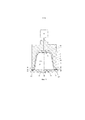
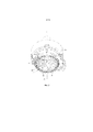
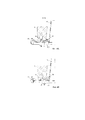
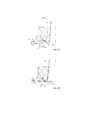
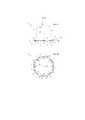
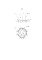
Следовательно, согласно указанному первому аспекту изобретения в настоящем изобретении обеспечивается капсула, содержащая вещество для приготовления напитка путем экстрагирования и/или растворения этого вещества посредством подачи в капсулу текучей среды под давлением, причем капсула содержит алюминиевый корпус капсулы, имеющий центральную ось корпуса капсулы, и при этом окружное направление капсулы проходит вокруг указанной центральной оси корпуса капсулы, указанный алюминиевый корпус капсулы обеспечен нижней частью, боковой стенкой и выступающей наружу кромкой, капсула дополнительно содержит алюминиевую крышку, прикрепленную к выступающей наружу кромке, крышка герметично закрывает капсулу, при этом боковая стенка, нижняя часть и крышка ограничивают внутреннее пространство капсулы, и при этом крышка имеет внешнюю накрывающую поверхность, обращенную в сторону от внутреннего пространства, и при этом капсула дополнительно содержит уплотнительный элемент на выступающей наружу кромке для обеспечения непроницаемого для текучей среды контакта с внешним элементом устройства для приготовления напитка, если капсула расположена во внешнем элементе устройства для приготовления напитка, а внешний элемент закрыт с помощью закрывающего элемента устройства для приготовления напитка, такого как экстракционная пластина устройства для приготовления напитка, таким образом, что выступающая наружу кромка капсулы и по меньшей мере часть уплотнительного элемента капсулы по существу взаимодействуют с обеспечением герметизации с внешним элементом устройства для приготовления напитка, причем внешний элемент устройства для приготовления напитка содержит кольцевой элемент, имеющий центральную ось кольцевого элемента и свободный контактный конец, указанный свободный контактный конец кольцевого элемента необязательно обеспечен множеством радиально проходящих открытых канавок, отличающаяся тем, что капсула дополнительно содержит упругую опорную конструкцию, прикрепленную к внешней накрывающей поверхности крышки в области прикрепления опорной конструкции внешней накрывающей поверхности, при этом область прикрепления опорной конструкции, как видно в проекции вдоль центральной оси корпуса капсулы, проходит, по меньшей мере частично, вдоль выступающей наружу кромки и, по меньшей мере частично, в окружном направлении капсулы таким образом, что, если капсула свободно покоится с расположением ее упругой опорной конструкции на полностью ровной опорной поверхности, упругая опорная конструкция обеспечивает промежуток между выступающей наружу кромкой и указанной полностью ровной опорной поверхностью, причем указанный промежуток является постоянным по всему окружному направлению капсулы.Therefore, according to said first aspect of the invention, the present invention provides a capsule containing a substance for preparing a beverage by extracting and / or dissolving the substance by feeding a pressurized fluid into the capsule, the capsule comprising an aluminum capsule body having a central axis of the capsule body, and the circumferential direction of the capsule extends around said central axis of the capsule body, said aluminum capsule body is provided with a bottom part, a side wall and an outwardly projecting edge, the capsule further comprises an aluminum cap attached to the outwardly projecting edge, the cap hermetically closes the capsule, while the side wall is lower the part and the lid define the inner space of the capsule, and the lid has an outer covering surface facing away from the inner space, and wherein the capsule further comprises a sealing element on the outwardly projecting edge for o providing fluid-tight contact with the outer member of the beverage preparation device if the capsule is located in the outer member of the beverage preparation device and the outer member is closed by a cover of the beverage preparation device, such as the extraction plate of the beverage preparation device, thus that the outwardly projecting edge of the capsule and at least part of the sealing element of the capsule substantially cooperate to provide a seal with an outer element of the beverage preparation device, wherein the outer element of the beverage preparation device comprises an annular element having a central axis of the annular element and a free contact end, said free the contact end of the annular element is optionally provided with a plurality of radially extending open grooves, characterized in that the capsule further comprises a resilient support structure attached to the outer covering surface Cover surfaces in the attachment region of the support structure of the outer covering surface, the attachment region of the support structure, as seen in projection along the central axis of the capsule body, extends at least partially along the outwardly projecting edge and at least partially in the circumferential direction of the capsule such that if the capsule rests freely with its resilient support structure on a completely flat support surface, the resilient support structure provides a gap between the outwardly projecting edge and said completely flat support surface, said gap being constant over the entire circumferential direction of the capsule.
Благодаря упругости упругой опорной конструкции на внешней накрывающей поверхности крышки капсулы упругая опорная конструкция будет автоматически адаптироваться к определенной величине вышеуказанных нежелательных наклонов и/или деформаций закрывающего элемента относительно внешнего элемента. Т.е. в процессе использования некоторые части упругой опорной конструкции будет деформироваться больше, чем другие части упругой опорной конструкции. Это означает, что несмотря на нежелательное отклонение и/или деформацию закрывающего элемента относительно внешнего элемента, уплотнительный элемент на выступающей наружу кромке капсулы будет иметь лучший непроницаемый для текучей среды контакт с внешним элементом устройства для приготовления напитка. Следовательно, это приводит к уменьшению утечки текучей среды за уплотнительный элемент на выступающей наружу кромке капсулы.Due to the resilience of the resilient support structure on the outer covering surface of the capsule lid, the resilient support structure will automatically adapt to a certain amount of the aforementioned undesirable tilts and / or deformations of the closure member relative to the outer member. Those. during use, some portions of the resilient support structure will deform more than other parts of the resilient support structure. This means that despite the undesirable deflection and / or deformation of the closure relative to the outer element, the sealing element on the outwardly projecting edge of the capsule will have better fluid-tight contact with the outer element of the beverage preparation device. Consequently, this results in less fluid leakage past the sealing element at the outwardly projecting edge of the capsule.
Упругая опорная конструкция может быть установлена с возможностью отсоединения на внешней накрывающей поверхности крышки или прикреплена к ней, например, путем сварки или с помощью адгезива.The resilient support structure can be detachably mounted to or attached to the outer covering surface of the lid, for example, by welding or using an adhesive.
В случае, когда упругая опорная конструкция образована одной или более отдельными деталями, прикрепленными к внешней накрывающей поверхности крышки, упругая опорная конструкция может быть установлена на капсуле как одна или несколько цельных деталей. В альтернативном варианте осуществления она может быть нанесена в жидкой или вязкой форме, а затем отверждена (например, путем полимеризации) после нанесения на внешнюю накрывающую поверхность крышки, что имеет место, например, при нанесении силикона.In the case where the resilient support structure is formed by one or more separate pieces attached to the outer covering surface of the lid, the resilient support structure may be mounted on the capsule as one or more integral pieces. In an alternative embodiment, it can be applied in liquid or viscous form and then cured (eg, by polymerization) after being applied to the outer cover surface of the lid, as is the case, for example, when silicone is applied.
В качестве материала упругой опорной конструкции предпочтительно используются резино-упругие материалы. Термин «резино-упругий» означает любой подходящий материал, обладающий упругостью резины, включая, без ограничений, эластомеры, силиконы, пластмассы, латекс, балату и другие.As the material of the elastic support structure, rubber-elastic materials are preferably used. The term "rubber-resilient" means any suitable material that has the elasticity of rubber, including, but not limited to, elastomers, silicones, plastics, latex, balata, and others.
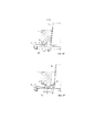
Предпочтительный вариант осуществления изобретения включает такие дополнительные признаки, что когда капсула расположена во внешнем элементе устройства для приготовления напитка, а внешний элемент закрыт с помощью закрывающего элемента устройства для приготовления напитка, упругая опорная конструкция вдоль частей окружного направления капсулы определяет каналы утечки напитка, проходящие, по меньшей мере радиально, через упругую опорную конструкцию и проходящие между внешней накрывающей поверхностью крышки капсулы и закрывающим элементом устройства для приготовления напитка.A preferred embodiment of the invention includes additional features such that when the capsule is positioned in the outer member of the beverage preparation device and the outer member is closed by the cover member of the beverage preparation device, the resilient support structure along the circumferential direction portions of the capsule defines beverage leakage channels extending along the at least radially, through the resilient support structure and extending between the outer cover surface of the capsule lid and the cover of the beverage preparation device.
Следует отметить, что используемое в настоящем документе состояние, в котором капсула расположена во внешнем элементе, в то время как внешний элемент закрыт с помощью закрывающего элемента, как указано выше, относится к состоянию закрытия, при котором соответствующее запирающее усилие находится в диапазоне 500-8000 Н, предпочтительно 1000-4000 Н.It should be noted that, as used herein, the state in which the capsule is located in the outer member while the outer member is closed by the closure member, as indicated above, refers to a closed state in which the corresponding closing force is in the range of 500-8000 H, preferably 1000-4000 N.
Благодаря каналам утечки напитка, проходящим, по меньшей мере радиально, через упругую опорную конструкцию, в процессе использования обеспечивается снижение давления на нижнем по потоку конце пути текучей среды. Указанное снижение давления на нижнем по потоку конце пути текучей среды автоматически уменьшает давление текучей среды в расположенных выше по потоку местах пути прохождения текучей среды, например на уплотнительном элементе на выступающей наружу кромке капсулы, что в данных обстоятельствах может обеспечивать дополнительное уменьшение протекания текучей среды за уплотнительный элемент на выступающей наружу кромке капсулы.The beverage leakage channels at least radially through the resilient support structure provide a pressure reduction at the downstream end of the fluid path during use. This pressure reduction at the downstream end of the fluid path automatically reduces the fluid pressure at upstream locations in the fluid path, for example at the sealing element on the outwardly projecting edge of the capsule, which in these circumstances can further reduce fluid flow past the seal. element on the outwardly projecting edge of the capsule.
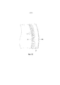
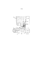
В «основном предпочтительном варианте осуществления капсулы» в соответствии с упомянутым выше первым аспектом изобретения уплотнительный элемент составляет одно целое с выступающей наружу кромкой и содержит по меньшей мере один выступ, выступающий из выступающей наружу кромки, причем указанный по меньшей мере один выступ содержит верхнюю часть выступа, при этом по меньшей мере один выступ выполнен таким образом, что его верхняя часть прилагает радиальное усилие к свободному контактному концу кольцевого элемента, если капсула расположена во внешнем элементе устройства для приготовления напитка, а внешний элемент закрыт с помощью закрывающего элемента устройства для приготовления напитка.In the "generally preferred embodiment of the capsule" according to the aforementioned first aspect of the invention, the sealing member is integral with the outwardly projecting lip and comprises at least one projection projecting from the outwardly projecting edge, said at least one projection comprising an upper portion of the projection wherein at least one protrusion is made in such a way that its upper part applies a radial force to the free contact end of the annular element if the capsule is located in the outer element of the beverage preparation device and the outer element is closed by the cover of the beverage preparation device.
Указанный выше основной предпочтительный вариант осуществления капсулы объясняется следующим образом.The above main preferred embodiment of the capsule is explained as follows.
В упомянутой выше системе, известной из EP1700548B1, капсула оснащена уплотнительным элементом, имеющим форму уступа, т.е. представляющим собой резкое увеличение диаметра боковой стенки капсулы, а внешний элемент этой известной системы имеет уплотнительную поверхность, воздействующую на уплотнительный элемент, обеспечивая отклонение уплотнительного элемента, причем уплотнительная поверхность наклонена таким образом, чтобы отклонение уплотнительного элемента приводило к деформации уступа внутрь и вниз. Кроме того, в известной системе внешний элемент содержит держатель капсулы и ручной или автоматический механизм для относительного смещения внешнего элемента и держателя капсулы. Ручной или автоматический механизм прикладывает усилие к уплотнительному элементу капсулы во время закрытия внешнего элемента на держателе капсулы. Такое усилие должно обеспечивать непроницаемое для текучей среды уплотнение между внешним элементом и капсулой. Поскольку ручной или автоматический механизм расположен с возможностью перемещения относительно основания, возможности герметизации системы могут зависеть от давления текучей среды, впрыскиваемой средством впрыска текучей среды. При увеличении давления текучей среды также возрастает усилие между уплотнительным элементом капсулы и свободным концом внешнего элемента, и, следовательно, также возрастает усилие между уплотнительным элементом капсулы и свободным концом внешнего элемента. Уплотнительный элемент капсулы должен быть расположен таким образом, чтобы при достижении максимального давления текучей среды во внешнем элементе уплотнительный элемент по-прежнему обеспечивал непроницаемый для текучей среды контакт между внешним элементом и капсулой. Однако при этом уплотнительный элемент также должен быть расположен таким образом, чтобы перед варкой или в начале варки, когда давление текучей среды во внешнем элементе снаружи капсулы является относительно низким, уплотнительный элемент также обеспечивал непроницаемый для текучей среды контакт между внешним элементом и капсулой. Если в начале варки не будет обеспечиваться непроницаемый для текучей среды контакт между капсулой и внешним элементом, произойдет утечка. При этом в случае возникновения утечки существует реальная вероятность того, что давление во внешнем элементе и снаружи капсулы увеличится в недостаточной степени для увеличения усилия, которое оказывается на уплотнительный элемент посредством свободного конца внешнего элемента при перемещении внешнего элемента к держателю капсулы с помощью ручного или автоматического механизма. Только в случае достаточной первоначальной герметизации давление во внешнем элементе будет увеличиваться, способствуя также увеличению усилия, которое оказывается на уплотнительный элемент капсулы посредством свободного конца внешнего элемента, настолько, чтобы обеспечить достаточный непроницаемый для текучей среды контакт и при повышенном давлении текучей среды. Более того, такое повышенное давление текучей среды снаружи капсулы также обеспечивает увеличенное давление текучей среды внутри капсулы, что крайне важно, если капсула обеспечена крышкой, выполненной с возможностью разрыва разрывных элементов (также называемых экстракционной пластиной) держателя капсулы устройства для приготовления напитка под воздействием давления текучей среды в капсуле.In the aforementioned system known from EP1700548B1, the capsule is equipped with a shoulder-shaped sealing element, i. E. representing a sharp increase in the diameter of the side wall of the capsule, and the outer element of this known system has a sealing surface acting on the sealing element, providing a deflection of the sealing element, and the sealing surface is inclined so that the deflection of the sealing element leads to deformation of the ledge inward and downward. In addition, in the known system, the outer member comprises a capsule holder and a manual or automatic mechanism for relative displacement of the outer member and the capsule holder. A manual or automatic mechanism applies force to the capsule sealing member during the closure of the outer member on the capsule holder. Such force should provide a fluid-tight seal between the outer member and the capsule. Since the manual or automatic mechanism is movable relative to the base, the sealing capability of the system may depend on the pressure of the fluid injected by the fluid injection means. As the fluid pressure increases, the force between the capsule sealing member and the free end of the outer member also increases, and hence the force between the capsule sealing member and the free end of the outer member also increases. The sealing element of the capsule should be positioned such that when the maximum fluid pressure in the outer element is reached, the sealing element still provides a fluid-tight contact between the outer element and the capsule. However, the sealing element must also be positioned so that before cooking or at the beginning of cooking, when the fluid pressure in the outer element outside the capsule is relatively low, the sealing element also provides a fluid-tight contact between the outer element and the capsule. If, at the start of cooking, no fluid-tight contact is made between the capsule and the outer member, leakage will occur. In this case, in the event of a leak, there is a real possibility that the pressure in the outer element and outside the capsule will not increase sufficiently to increase the force that is exerted on the sealing element by the free end of the outer element when the outer element is moved towards the capsule holder using a manual or automatic mechanism. ... Only if there is sufficient initial sealing will the pressure in the outer member increase, also contributing to an increase in the force exerted on the capsule sealing member by the free end of the outer member, enough to provide sufficient fluid-tight contact even at increased fluid pressure. Moreover, such an increased pressure of the fluid outside the capsule also provides an increased pressure of the fluid inside the capsule, which is extremely important if the capsule is provided with a lid capable of bursting rupture elements (also called an extraction plate) of the capsule holder of the beverage preparation device under the pressure of the fluid. environment in the capsule.
Таким образом, уплотнительный элемент является элементом, который имеет очень важное значение в конструкции. Он должен быть выполнен с возможностью обеспечения непроницаемого для текучей среды контакта между внешним элементом и капсулой при относительно низком давлении текучей среды, когда свободный конец внешнего элемента воздействует на уплотнительный элемент с относительно небольшим усилием, но он также должен обеспечивать непроницаемый для текучей среды контакт и при намного более высоком давлении текучей среды во внешнем элементе снаружи капсулы, когда на уплотнительный элемент капсулы воздействует более высокое усилие со стороны свободного конца внешнего элемента. В частности, когда свободный контактный конец внешнего элемента обеспечен радиально проходящими открытыми канавками, которые действуют в качестве каналов подачи воздуха, если усилие между внешним элементом и держателем капсулы ослабляется настолько, чтобы пользователю было легче извлечь капсулу, уплотнительный элемент также должен быть способен «закрывать» радиально проходящие открытые канавки для обеспечения эффективного уплотнения.Thus, the sealing element is a very important element in the design. It should be capable of providing fluid-tight contact between the outer member and the capsule at a relatively low fluid pressure when the free end of the outer member acts on the sealing member with relatively little force, but it should also provide fluid-tight contact when a much higher fluid pressure in the outer member outside the capsule when a higher force is exerted on the sealing member of the capsule from the free end of the outer member. In particular, when the free contact end of the outer member is provided with radially extending open grooves that act as air ducts, if the force between the outer member and the capsule holder is weakened so that it is easier for the user to remove the capsule, the sealing member must also be able to "close" radially extending open grooves for effective sealing.
Целью упомянутого выше основного предпочтительного варианта осуществления капсулы является обеспечение альтернативной капсулы с альтернативным уплотнительным элементом, который является относительно простым в изготовлении, который безопасен для окружающей среды в случае утилизации капсулы после ее использования и/или который обеспечивает удовлетворительное уплотнение как при относительно низком давлении текучей среды, если на уплотнительный элемент оказывается лишь относительно небольшое усилие посредством свободного конца внешнего элемента (иногда также называемом первоначальным уплотнением), так и при гораздо более высоком давлении текучей среды, если на уплотнительный элемент капсулы оказывается большее усилие (например, во время варки) посредством свободного конца внешнего элемента, даже если внешний элемент, на котором имеется свободный контактный конец, обеспечен радиально проходящими открытыми канавками.The purpose of the aforementioned main preferred embodiment of the capsule is to provide an alternative capsule with an alternative sealing member that is relatively easy to manufacture, which is environmentally friendly if the capsule is disposed of after use, and / or which provides a satisfactory seal as at a relatively low fluid pressure. if only a relatively small force is exerted on the sealing element by the free end of the outer element (sometimes also called the initial seal), and at a much higher fluid pressure if more force is exerted on the sealing element of the capsule (for example, during cooking) by means of the free the end of the outer member even if the outer member, which has a free contact end, is provided with radially extending open grooves.
Для этой цели и, как упоминалось выше, капсула в соответствии с указанным выше основным предпочтительным вариантом осуществления капсулы отличается тем, что уплотнительный элемент составляет одно целое с выступающей наружу кромкой и содержит по меньшей мере один выступ, выступающий из выступающей наружу кромки, причем по меньшей мере один выступ содержит верхнюю часть выступа, и при этом по меньшей мере один выступ выполнен таким образом, что его верхняя часть прилагает радиальное усилие к свободному контактному концу кольцевого элемента, если капсула расположена во внешнем элементе устройства для приготовления напитка, а внешний элемент закрыт с помощью закрывающего элемента устройства для приготовления напитка.For this purpose, and as mentioned above, the capsule according to the aforementioned main preferred embodiment of the capsule is characterized in that the sealing element is integral with the outwardly projecting edge and comprises at least one projection projecting from the outwardly projecting edge, at least at least one projection comprises an upper part of the projection, and the at least one projection is designed in such a way that its upper part applies a radial force to the free contact end of the annular element if the capsule is located in the outer element of the device for preparing a beverage, and the outer element is closed with by means of a closing element of the beverage preparation device.
Поскольку уплотнительный элемент составляет одно целое с выступающей наружу кромкой и содержит по меньшей мере один выступ, верхняя часть которого прилагает радиальное усилие к свободному контактному концу кольцевого элемента, можно достичь удовлетворительной герметизации, если капсула расположена во внешнем элементе устройства для приготовления напитка, а внешний элемент закрыт с помощью закрывающего элемента устройства для приготовления напитка. Такой уплотнительный элемент относительно прост в изготовлении. Кроме того, капсула может обеспечивать удовлетворительную герметизацию со свободным контактным концом, снабженным радиально проходящими открытыми канавками. Кроме того, такая герметизация упрощает размещение капсулы внутри устройства для приготовления напитка.Since the sealing element is integral with the outwardly projecting edge and contains at least one projection, the upper part of which exerts a radial force on the free contact end of the annular element, a satisfactory sealing can be achieved if the capsule is located in the outer element of the beverage preparation device and the outer element closed by the cover of the beverage preparation device. Such a sealing element is relatively easy to manufacture. In addition, the capsule can provide a satisfactory seal with a free contact end provided with radially extending open grooves. In addition, this sealing facilitates the placement of the capsule inside the beverage preparation device.
В данной заявке наличие непроницаемого для текучей среды контакта означает, что за счет утечки между свободным контактным концом и уплотнительным элементом капсулы может вытекать наружу 0-6%, предпочтительно 0-4%, более предпочтительно 0-2,5% от всей текучей среды, поданной во внешний элемент для приготовления напитка.In this application, the presence of a fluid-tight contact means that 0-6%, preferably 0-4%, more preferably 0-2.5% of the total fluid can be leaked out between the free contact end and the sealing element of the capsule. fed into the external element for preparing a beverage.
Особое преимущество настоящего изобретения заключается в том, что в одном варианте осуществления капсулы в качестве вещества для приготовления напитка капсула содержит извлекаемый продукт, причем извлекаемый продукт предпочтительно представлен в количестве 5-20 грамм, предпочтительно 5-10 грамм, более предпочтительно 5-7 грамм извлекаемого продукта, например обжаренного и молотого кофе.A particular advantage of the present invention is that, in one embodiment of the capsule, as a beverage preparation material, the capsule contains a extractable product, the extractable product being preferably present in an amount of 5-20 grams, preferably 5-10 grams, more preferably 5-7 grams of extractable product such as roasted and ground coffee.
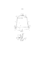
В одном варианте осуществления капсулы в соответствии с изобретением, который особенно прост в изготовлении, внешний диаметр выступающей наружу кромки капсулы больше диаметра нижней части капсулы. Предпочтительно, чтобы внешний диаметр выступающей наружу кромки составлял около 37,1 мм, а диаметр нижней части капсулы - около 23,3 мм.In one embodiment of the capsule according to the invention, which is particularly easy to manufacture, the outer diameter of the outwardly projecting edge of the capsule is greater than the diameter of the lower part of the capsule. Preferably, the outer diameter of the outwardly projecting rim is about 37.1 mm and the diameter of the bottom of the capsule is about 23.3 mm.
Особое преимущество настоящего изобретения заключается в том, что в одном варианте осуществления капсулы толщина алюминиевого корпуса капсулы такая, что она легко деформируется, если капсула расположена во внешнем элементе устройства для приготовления напитка, а внешний элемент закрыт с помощью закрывающего элемента устройства для приготовления напитка, толщина алюминиевого корпуса капсулы предпочтительно составляет 20-200 микрометров, предпочтительно 100 микрометров.A particular advantage of the present invention is that, in one embodiment of the capsule, the thickness of the aluminum capsule body is such that it is easily deformed if the capsule is located in the outer member of the beverage preparation device and the outer member is closed by the cover member of the beverage preparation device, the thickness the aluminum capsule body is preferably 20-200 micrometers, preferably 100 micrometers.
Особое преимущество настоящего изобретения заключается в том, что в одном варианте осуществления капсулы толщина алюминиевой крышки составляет 15-65 микрометров, предпочтительно 30-45 микрометров, более предпочтительного 39 микрометров.A particular advantage of the present invention is that in one embodiment of the capsule, the thickness of the aluminum cap is 15-65 micrometers, preferably 30-45 micrometers, more preferably 39 micrometers.
В варианте осуществления капсулы в соответствии с изобретением толщина алюминиевой крышки меньше толщины стенки алюминиевого корпуса капсулы.In an embodiment of a capsule according to the invention, the thickness of the aluminum cap is less than the wall thickness of the aluminum body of the capsule.
В дополнительном варианте осуществлении капсулы в соответствии с изобретением алюминиевая крышка выполнена с возможностью разрыва на закрывающем элементе устройства для приготовления напитка, например на экстракционной пластине устройства для приготовления напитка, под воздействием давления текучей среды в капсуле.In a further embodiment of the capsule according to the invention, the aluminum cap is configured to break on the cover of the beverage preparation device, for example the extraction plate of the beverage preparation device, by the pressure of the fluid in the capsule.
В варианте осуществления капсулы в соответствии с настоящим изобретением, который особенно прост в изготовлении, боковая стенка алюминиевого корпуса капсулы имеет свободный конец, расположенный напротив нижней части, выступающую наружу кромку, проходящую от свободного конца боковой стенки в направлении, по меньшей мере по существу поперечном к центральной оси корпуса капсулы. Предпочтительно, чтобы выступающая наружу кромка содержала искривленный внешний край, что удобно для достижения удовлетворительной герметизации со свободным контактным концом, обеспеченным радиально проходящими открытыми канавками. Предпочтительно, чтобы радиус относительно центральной оси корпуса капсулы внутреннего края искривленного внешнего края выступающей наружу кромки составлял по меньшей мере 32 мм, чтобы обеспечить зазор от кольцеобразной торцевой поверхности внешнего элемента. Кроме того, предпочтительно, чтобы уплотнительный элемент располагался между свободным концом боковой стенки алюминиевого корпуса капсулы и внутренним краем искривленного внешнего края выступающей наружу кромки для обеспечения еще более удовлетворительной герметизации.In an embodiment of the capsule according to the present invention, which is particularly easy to manufacture, the side wall of the aluminum capsule body has a free end opposite the bottom, an outwardly projecting edge extending from the free end of the side wall in a direction at least substantially transverse to the central axis of the capsule body. Preferably, the outwardly projecting edge comprises a curved outer edge that is convenient to achieve a satisfactory seal with a free contact end provided with radially extending open grooves. Preferably, the radius with respect to the central axis of the capsule body of the inner edge of the curved outer edge of the outwardly projecting edge is at least 32 mm in order to provide clearance from the annular end surface of the outer member. In addition, it is preferred that the sealing member is located between the free end of the side wall of the aluminum capsule body and the inner edge of the curved outer edge of the outwardly projecting edge to provide an even more satisfactory sealing.
Чтобы искривленный внешний край не мешал работе многочисленных имеющихся в продаже и будущих устройств для приготовления напитка, наибольший размер искривленного внешнего края выступающей наружу кромки должен составлять около 1,2 миллиметра.To prevent the curved outer edge from interfering with the operation of numerous commercially available and future beverage preparation devices, the curved outer edge of the outwardly projecting edge should have a maximum dimension of about 1.2 millimeters.
Настоящее изобретение особенно эффективно для капсул, у которых внутренний диаметр свободного конца боковой стенки алюминиевого корпуса капсулы составляет около 29,5 мм. Расстояние между свободным концом боковой стенки алюминиевого корпуса капсулы и наиболее удаленной наружу точкой выступающей наружу кромки может составлять около 3,8 миллиметра. Предпочтительная высота алюминиевого корпуса капсулы составляет около 28,4 мм.The present invention is especially effective for capsules in which the inside diameter of the free end of the side wall of the aluminum capsule body is about 29.5 mm. The distance between the free end of the side wall of the aluminum capsule body and the outwardly farthest point of the outwardly projecting edge may be about 3.8 millimeters. The preferred height of the aluminum capsule body is about 28.4 mm.
В одном варианте осуществления капсулы в соответствии с изобретением, которую пользователю легче для вынимать из устройства для приготовления напитка после использования, алюминиевый корпус капсулы является усеченным, причем предпочтительно, чтобы боковая стенка алюминиевого корпуса капсулы с линией, поперечной к центральной оси корпуса капсулы, формировала угол около 97,5°.In one embodiment of the capsule according to the invention, which is easier for the user to remove from the beverage preparation device after use, the aluminum capsule body is truncated, it being preferred that the side wall of the aluminum capsule body with a line transverse to the central axis of the capsule body forms an angle about 97.5 °.
В преимущественном варианте осуществления капсулы в соответствии с изобретением нижняя часть алюминиевого корпуса капсулы имеет наибольший внутренний диаметр около 23,3 мм. Предпочтительно, чтобы нижняя часть алюминиевого корпуса капсулы имела усеченную форму и предпочтительно имела высоту нижней части около 4,0 мм и чтобы нижняя часть дополнительно имела по существу плоскую центральную часть, расположенную напротив крышки, с диаметром около 8,3 мм.In an advantageous embodiment of the capsule according to the invention, the lower portion of the aluminum capsule body has a largest inner diameter of about 23.3 mm. Preferably, the lower portion of the aluminum capsule body has a truncated shape and preferably has a lower portion height of about 4.0 mm and that the lower portion additionally has a substantially flat central portion opposite the lid with a diameter of about 8.3 mm.
Практически во всех случаях удовлетворительная герметизация может быть получена в варианте осуществления капсулы в соответствии с настоящим изобретением, в котором высота части уплотнительного элемента, с которой в первую очередь будет контактировать свободный конец внешнего элемента, когда внешний элемент закрыт, составляет по меньшей мере около 0,1 мм, более предпочтительно по меньшей мере 0,2 мм и наиболее предпочтительно по меньшей мере 0,8 мм, и не более 3 мм, более предпочтительно не более 2 мм и наиболее предпочтительно не более 1,2 мм.In almost all cases, a satisfactory sealing can be obtained in an embodiment of a capsule according to the present invention, in which the height of the portion of the sealing member with which the free end of the outer member will first contact when the outer member is closed is at least about 0. 1 mm, more preferably at least 0.2 mm, and most preferably at least 0.8 mm, and not more than 3 mm, more preferably not more than 2 mm, and most preferably not more than 1.2 mm.
В предпочтительном варианте осуществления капсулы в соответствии с изобретением капсула содержит внутреннюю поверхность, причем на внутренней поверхности по меньшей мере боковой стенки капсулы обеспечено внутреннее покрытие. В частности, при изготовлении капсулы методом глубокой вытяжки внутреннее покрытие упрощает процесс глубокой вытяжки. Если алюминиевая крышка капсулы прикреплена к выступающей наружу кромке посредством герметизирующего лака, тогда особое преимущество заключается в том, чтобы внутреннее покрытие состояло из того же материала, что и герметизирующий лак. В зависимости от используемого внутреннего покрытия предпочтительно, чтобы уплотнительный элемент не содержал внутреннего покрытия с целью предотвращения осыпания внутреннего покрытия с уплотнительного элемента.In a preferred embodiment of the capsule according to the invention, the capsule comprises an inner surface, wherein an inner coating is provided on the inner surface of at least the side wall of the capsule. In particular, when making a capsule using the deep drawing method, the inner coating facilitates the deep drawing process. If the aluminum cap of the capsule is attached to the outwardly projecting edge by means of a sealing lacquer, then it is of particular advantage that the inner lining consists of the same material as the sealing lacquer. Depending on the inner coating used, it is preferable that the sealing element does not contain an inner coating in order to prevent the inner coating from falling off the sealing element.
В дополнительном варианте осуществления капсулы в соответствии с изобретением капсула содержит внешнюю поверхность, причем на внешнюю поверхность нанесен цветной лак. Чтобы упростить глубокую вытяжку, предпочтительным является нанесение внешнего покрытия на внешнюю поверхность цветного лака. В зависимости от используемого цветного лака и внешнего покрытия предпочтительно, чтобы уплотнительный элемент не содержал цветного лака (и, следовательно, внешнего покрытия), чтобы предотвратить осыпание цветного лака/внешнего покрытия с уплотнительного элемента.In a further embodiment of the capsule according to the invention, the capsule comprises an outer surface, with a colored varnish applied to the outer surface. To facilitate deep drawing, it is preferable to apply an overcoat to the outside of the colored lacquer. Depending on the colored lacquer and outer coating used, it is preferable that the sealing element does not contain colored lacquer (and therefore no outer coating) in order to prevent the colored lacquer / outer coating from falling off the sealing element.
В еще одном варианте осуществления капсулы в соответствии с настоящим изобретением по меньшей мере один выступ содержит боковую стенку выступа, наклоненную относительно выступающей наружу кромки алюминиевого корпуса капсулы, причем боковая стенка выступа выполнена таким образом, что она легко деформируется, если капсула расположена во внешнем элементе устройства для приготовления напитка, а внешний элемент закрыт с помощью закрывающего элемента устройства для приготовления напитка. Это улучшает усилие, действующее на свободный контактный конец, и таким образом улучшает герметизацию. Также предпочтительно, когда расстояние между выступом и боковой стенкой алюминиевого корпуса капсулы такое, что свободный контактный конец кольцевого элемента контактирует посредством выступа и боковой стенки алюминиевого корпуса капсулы, если капсула расположена во внешнем элементе устройства для приготовления напитка, а внешний элемент закрыт с помощью закрывающего элемента устройства для приготовления напитка.In yet another embodiment of a capsule according to the present invention, at least one projection comprises a projection side wall inclined relative to an outwardly projecting edge of the aluminum capsule body, the projection side wall being designed so that it is easily deformed if the capsule is located in an external element of the device for preparing a beverage, and the outer member is closed by a cover member of the beverage preparation device. This improves the force on the free contact end and thus improves the seal. It is also preferable when the distance between the projection and the side wall of the aluminum capsule body is such that the free contact end of the annular element contacts by means of the projection and the side wall of the aluminum capsule body if the capsule is located in the outer element of the beverage preparation device and the outer element is closed by the closing element devices for preparing a drink.
В преимущественном варианте осуществления капсулы согласно настоящему изобретению уплотнительный элемент содержит, в дополнение к по меньшей мере одному выступу, выступающему из выступающей наружу кромки, ровный участок между верхней частью выступа и боковой стенкой алюминиевого корпуса капсулы. Для обеспечения герметизации предпочтительно, чтобы опора была образована выступом, ровным участком и боковой стенкой алюминиевого корпуса капсулы, причем расстояние между выступом и боковой стенкой такое, что свободный контактный конец кольцевого элемента охвачен выступом и боковой стенкой алюминиевого корпуса капсулы, если капсула расположена во внешнем элементе устройства для приготовления напитка, а внешний элемент закрыт с помощью закрывающего элемента устройства для приготовления напитка.In an advantageous embodiment of the capsule according to the present invention, the sealing member comprises, in addition to the at least one projection protruding from the outwardly projecting edge, a flat portion between the top of the projection and the side wall of the aluminum capsule body. To ensure sealing, it is preferable that the support is formed by a protrusion, a flat section and a side wall of the aluminum capsule body, the distance between the protrusion and the side wall is such that the free contact end of the annular element is surrounded by the protrusion and the side wall of the aluminum capsule body, if the capsule is located in the outer element device for preparing a beverage, and the outer element is closed by a cover member of the device for preparing a beverage.
Выступ, боковая стенка алюминиевого корпуса капсулы и ровный участок могут быть расположены таким образом, что свободный контактный конец кольцевого элемента контактирует с ровным участком, если капсула расположена во внешнем элементе устройства для приготовления напитка, а внешний элемент закрыт с помощью закрывающего элемента устройства для приготовления напитка.The protrusion, the side wall of the aluminum capsule body and the flat portion can be positioned such that the free contact end of the annular element contacts the flat portion if the capsule is located in the outer element of the beverage preparation device and the outer element is closed by the cover of the beverage preparation device ...
В альтернативном варианте осуществления уплотнительный элемент может содержать два разнесенных выступа, каждый из которых выступает из выступающей наружу кромки, и ровный участок между двумя выступами, причем расстояние между двумя выступами такое, что свободный контактный конец кольцевого элемента сжимается между сходящимися поверхностями двух выступов, если капсула расположена во внешнем элементе устройства для приготовления напитка, а внешний элемент закрыт с помощью закрывающего элемента устройства для приготовления напитка. Также предпочтительно, когда расстояние между двумя выступами такое, что свободный контактный конец кольцевого элемента контактирует с двумя выступами, если капсула расположена во внешнем элементе устройства для приготовления напитка, а внешний элемент закрыт с помощью закрывающего элемента устройства для приготовления напитка. В частности, удовлетворительное уплотнение может быть получено, когда два разнесенных выступа и ровный участок расположены таким образом, что свободный контактный конец кольцевого элемента контактирует с ровным участком, если капсула расположена во внешнем элементе устройства для приготовления напитка, а внешний элемент закрыт с помощью закрывающего элемента устройства для приготовления напитка. Капсула может предпочтительно содержать опору для внешнего элемента устройства для приготовления напитка, такую что, если капсула расположена во внешнем элементе устройства для приготовления напитка и внешний элемент закрыт с помощью закрывающего элемента устройства для приготовления напитка, опора охватывает по меньшей мере часть свободного контактного конца кольцевого элемента, и опора образована двумя выступами и ровным участком между ними.In an alternative embodiment, the sealing element may comprise two spaced apart protrusions, each protruding from an outwardly projecting edge, and a flat area between the two protrusions, the distance between the two protrusions such that the free contact end of the annular element is compressed between the converging surfaces of the two protrusions if the capsule is located in the outer element of the beverage preparation device, and the outer member is closed by the cover element of the beverage preparation device. It is also preferable when the distance between the two projections is such that the free contact end of the annular element contacts the two projections if the capsule is located in the outer element of the beverage preparation device and the outer member is closed by the cover of the beverage preparation device. In particular, a satisfactory seal can be obtained when two spaced protrusions and a flat portion are positioned such that the free contact end of the annular element contacts the flat portion if the capsule is located in the outer element of the beverage preparation device and the outer element is closed by the cover element devices for preparing a drink. The capsule may preferably comprise a support for an external member of the beverage preparation device such that if the capsule is located in an external member of the beverage preparation device and the external member is closed by a cover of the beverage preparation device, the support encompasses at least a portion of the free contact end of the annular member , and the support is formed by two protrusions and a flat section between them.
Ровный участок может быть по существу плоским или может содержать изогнутую часть. В частности, предпочтительным является вариант осуществления капсулы в соответствии с настоящим изобретением, в котором ровный участок имеет V-образную форму. Таким образом, свободный контактный конец кольцевого элемента зажат между двумя выступами, обеспечивая удовлетворительное уплотнение.The flat portion may be substantially flat or may include a curved portion. Particularly preferred is an embodiment of the capsule according to the present invention in which the flat portion is V-shaped. Thus, the free contact end of the annular member is clamped between the two protrusions to provide a satisfactory seal.
Дополнительной целью вариантов осуществления изобретения является достижение надежной герметизации при низком и высоком давлении относительно свободного контактного конца внешнего элемента, в частности с небольшой чувствительностью к изменениям диаметра, толщины и формы свободного контактного конца, которые имеют место у различных моделей варочных систем, и некруглости (например, овальности) свободного контактного конца и/или кромки капсулы. Последнее может быть, например, результатом сжатия капсул в сумке или тележке. В варианте осуществления изобретения эта цель достигается тем, что первый из двух выступов выступает дальше от участка основания выступающей наружу кромки, к которому прикреплена крышка, чем второй из двух выступов.An additional objective of the embodiments of the invention is to achieve reliable sealing at low and high pressure relative to the free contact end of the outer element, in particular with little sensitivity to changes in diameter, thickness and shape of the free contact end, which occur in different models of cooking systems, and out-of-roundness (for example , ovality) of the free contact end and / or the edge of the capsule. The latter can be, for example, the result of the compression of the capsules in a bag or trolley. In an embodiment of the invention, this object is achieved in that the first of the two protrusions protrudes further from the base portion of the outwardly projecting edge to which the cover is attached than the second of the two protrusions.
Если при закрытии внешнего элемента слишком большая часть одного из выступов, выступающего дальше всего от участка основания, расположена под в осевом направлении соосно со свободным контактным концом, она отжимается радиально, так что свободный контактный конец проходит вместе с указанным дальше выступающим выступом. Это радиальное смещение также захватывает другой из выступов радиально по направлению к свободному контактному концу, так что он точно располагается для сильного герметизирующего взаимодействия со свободным контактным концом. Кроме того, один дальше выступающий из выступов выполнен с возможностью деформации в радиальном направлении на относительно большом расстоянии, так что он может адаптироваться к относительно большим отклонениям, в то время как другой из выступов является относительно жестким, что является преимуществом для обеспечения сильного герметизирующего давления.If, when the outer member is closed, too much of one of the protrusions projecting furthest from the base portion is axially coaxially below the free contact end, it is pushed radially so that the free contact end extends with the further protruding protrusion. This radial displacement also engages the other of the protrusions radially towards the free contact end so that it is precisely positioned for strong sealing engagement with the free contact end. In addition, one further protruding from the protrusions is designed to deform in the radial direction at a relatively large distance, so that it can adapt to relatively large deflections, while the other of the protrusions is relatively rigid, which is an advantage to provide a strong sealing pressure.
Если первый из выступов является внутренним из двух выступов, капсула особенно подходит для использования в коммерчески доступных устройствах, таких как Citiz, Lattisima, U, Maestria, Pixie, Inissia и Essenza, в которых свободный контактный конец кольцевого элемента снабжен множеством радиально проходящих открытых канавок, причем канавки глубже на участке внутренней поверхности, чем на участке внешней поверхности свободного контактного конца, или канавки отсутствуют на участке внешней поверхности свободного контактного конца. В таких устройствах обеспечивается надежное и точное расположение уплотнения между вторым из выступов и относительно гладким участком внешней поверхности свободного контактного конца.If the first of the projections is the inner of the two projections, the capsule is particularly suitable for use in commercially available devices such as Citiz, Lattisima, U, Maestria, Pixie, Inissia and Essenza, in which the free contact end of the annular member is provided with a plurality of radially extending open grooves. wherein the grooves are deeper in the inner surface portion than in the outer surface portion of the free contact end, or there are no grooves in the outer surface portion of the free contact end. Such devices provide a reliable and accurate seal between the second of the protrusions and the relatively smooth portion of the outer surface of the free contact end.
Для достижения надежной герметизации также выгодно, чтобы первый из двух выступов имел крайний верхний конец, проходящий вокруг оси капсулы с диаметром от 31,9 до 32,4 мм, а второй из двух выступов имел крайний верхний конец, проходящий вокруг оси капсулы с диаметром от 29,2 до 29,8 мм. Таким образом, при использовании в коммерчески доступных кофеварках, таких как Citiz, Lattisima, U, Maestria, Pixie, Inissia и Essenza, внешняя краевая область свободного конца внешнего элемента прочно прижимается ко второму выступу.To achieve a reliable seal, it is also advantageous for the first of the two protrusions to have an extreme upper end extending around the axis of the capsule with a diameter of 31.9 to 32.4 mm, and the second of the two protrusions to have an extreme upper end extending around the axis of the capsule with a diameter of from 29.2 to 29.8 mm. Thus, when used in commercially available coffee makers such as Citiz, Lattisima, U, Maestria, Pixie, Inissia and Essenza, the outer edge region of the free end of the outer member is firmly pressed against the second protrusion.
Если ровный участок находится на некотором расстоянии в осевом направлении от крышки, указанная область между первым и вторым выступами смещена в осевом направлении к крышке, так как внешний элемент закрывается посредством закрывающего элемента устройства для приготовления напитка. Это приводит к тому, что первый выступ и второй выступ деформируются в направлении свободного контактного конца кольцевого элемента из-за наклона и «опрокидывания» первого выступа и второго выступа, тем самым увеличивая радиальное контактное давление, действующее на свободный контактный конец кольцевого элемента, что способствует достижению удовлетворительной герметизации.If the flat area is at some axial distance from the lid, the region between the first and second protrusions is axially offset towards the lid, since the outer element is closed by the cover of the beverage preparation device. This causes the first protrusion and the second protrusion to deform towards the free contact end of the annular element due to the tilting and "overturning" of the first protrusion and the second protrusion, thereby increasing the radial contact pressure acting on the free contact end of the annular element, which contributes to achieving a satisfactory seal.
В «основном предпочтительном варианте осуществления системы» в соответствии с указанным выше вторым аспектом изобретения уплотнительный элемент составляет одно целое с выступающей наружу кромкой и содержит по меньшей мере один выступ, выступающий из выступающей наружу кромки, причем указанный по меньшей мере один выступ содержит верхнюю часть выступа, и при этом по меньшей мере один выступ выполнен таким образом, что его верхняя часть прилагает радиальное усилие к свободному контактному концу кольцевого элемента, если капсула расположена во внешнем элементе устройства для приготовления напитка, а внешний элемент закрыт с помощью закрывающего элемента устройства для приготовления напитка.In the "main preferred embodiment of the system" according to the above second aspect of the invention, the sealing member is integral with the outwardly projecting lip and comprises at least one projection projecting from the outwardly projecting edge, said at least one projection comprising an upper portion of the projection , and wherein at least one projection is made in such a way that its upper part applies a radial force to the free contact end of the annular element if the capsule is located in the outer element of the beverage preparation device, and the outer element is closed by the cover element of the beverage preparation device ...
Поскольку уплотнительный элемент составляет одно целое с выступающей наружу кромкой и содержит по меньшей мере один выступ, верхняя часть которого прилагает радиальное усилие к свободному контактному концу кольцевого элемента, можно достичь удовлетворительной герметизации, если капсула расположена во внешнем элементе устройства для приготовления напитка, а внешний элемент закрыт с помощью закрывающего элемента устройства для приготовления напитка. Такой уплотнительный элемент относительно прост в изготовлении. Кроме того, капсула может обеспечивать удовлетворительную герметизацию со свободным контактным концом, снабженным радиально проходящими открытыми канавками.Since the sealing element is integral with the outwardly projecting edge and contains at least one projection, the upper part of which exerts a radial force on the free contact end of the annular element, a satisfactory sealing can be achieved if the capsule is located in the outer element of the beverage preparation device and the outer element closed by the cover of the beverage preparation device. Such a sealing element is relatively easy to manufacture. In addition, the capsule can provide a satisfactory seal with a free contact end provided with radially extending open grooves.
Выступ или выступы могут выступать из по меньшей мере одного участка основания кромки, к которому прикреплена крышка. Выступы или выступы могут выступать в осевом направлении от участка основания в направлении от крышки. Верхняя часть выступа может составлять часть выступа, например половину, треть или четверть выступа, которая является наиболее дистальной в осевом направлении от участка основания.The protrusion or protrusions can protrude from at least one portion of the lip base to which the cover is attached. The protrusions or protrusions can protrude axially from the base portion in a direction away from the cover. The upper portion of the protrusion may form a portion of the protrusion, such as half, one third or a quarter of the protrusion, that is most axially distal from the base portion.
Что касается предпочтительных вариантов осуществления системы, как указано в зависимых пунктах формулы изобретения, которые относятся к тем же признакам, что и признаки зависимых пунктов формулы изобретения капсулы, делается ссылка на вышеизложенное.With regard to preferred embodiments of the system, as indicated in the dependent claims, which relate to the same features as those of the capsule dependent claims, reference is made to the foregoing.
Настоящее изобретение особенно подходит для системы в соответствии с изобретением, в которой при использовании максимальное давление текучей среды во внешнем элементе устройства для приготовления напитка находится в диапазоне 6-20 бар, предпочтительно 12-18 бар. Даже при таких высоких значениях давления можно обеспечить удовлетворительное уплотнение между капсулой и устройством для приготовления напитка.The present invention is particularly suitable for a system according to the invention in which, in use, the maximum fluid pressure in the external member of the beverage preparation device is in the range of 6-20 bar, preferably 12-18 bar. Even at such high pressures, a satisfactory seal between the capsule and the beverage preparation device can be achieved.
Предпочтительно, чтобы система была устроена так, чтобы при использовании во время варки свободный конец внешнего элемента устройства для приготовления напитка воздействовал с силой F2 на уплотнительный элемент капсулы, обеспечивая непроницаемый для текучей среды контакт между выступающей наружу кромкой капсулы и внешним элементом устройства для приготовления напитка, причем F2 находится в диапазоне 500-1500 Н, предпочтительно в диапазоне 750-1250 Н, когда давление P2 текучей среды во внешнем элементе устройства для приготовления напитка снаружи капсулы находится в диапазоне 6-20 бар, предпочтительно от 12 до 18 бар. В частности, система устроена так, чтобы при использовании перед варкой или в начале варки свободный конец внешнего элемента устройства для приготовления напитка воздействовал с силой F1 на уплотнительный элемент капсулы, обеспечивая непроницаемый для текучей среды контакт между выступающей наружу кромкой капсулы и внешним элементом устройства для приготовления напитка, причем F1 находится в диапазоне 30-150 Н, предпочтительно в диапазоне 40-150 Н, более предпочтительно 50-100 Н, когда давление P1 текучей среды во внешнем элементе устройства для приготовления напитка снаружи капсулы находится в диапазоне 0,1-4 бар, предпочтительно 0,1-1 бар.Preferably, the system is designed so that, when used during brewing, the free end of the outer element of the beverage preparation device acts with a force F2 on the sealing element of the capsule, providing a fluid-tight contact between the outwardly projecting edge of the capsule and the outer element of the beverage preparation device. moreover, F2 is in the range of 500-1500 N, preferably in the range 750-1250 N, when the pressure P2 of the fluid in the external element of the device for preparing a beverage outside the capsule is in the range of 6-20 bar, preferably from 12 to 18 bar. In particular, the system is designed so that, when used before brewing or at the beginning of brewing, the free end of the outer element of the beverage preparation device acts with force F1 on the capsule sealing element, providing a fluid-tight contact between the outwardly projecting edge of the capsule and the outer element of the preparation device. beverage, wherein F1 is in the range of 30-150 N, preferably in the range 40-150 N, more preferably 50-100 N, when the pressure P1 of the fluid in the external element of the beverage preparation device outside the capsule is in the range of 0.1-4 bar , preferably 0.1-1 bar.
В варианте осуществления системы в соответствии с изобретением, в котором множество радиально проходящих открытых канавок расположены равномерно относительно друг друга в касательном направлении свободного контактного конца кольцевого элемента устройства для приготовления напитка таким образом, чтобы пользователю было проще извлечь капсулу, и в то же время чтобы все еще обеспечивалось удовлетворительное уплотнение между капсулой и устройством для приготовления напитка.In an embodiment of the system according to the invention, in which a plurality of radially extending open grooves are evenly spaced relative to each other in the tangential direction of the free contact end of the annular element of the beverage preparation device so that it is easier for the user to remove the capsule and at the same time that all a satisfactory seal was still ensured between the capsule and the beverage preparation device.
В преимущественном варианте осуществления системы в соответствии с изобретением самая длинная касательная ширина каждой канавки (между гребнями, т. е. равная шагу канавок) составляет 0,9-1,1 мм, предпочтительно 0,95-1,05 мм, более предпочтительно 0,98-1,02 мм, где максимальная высота каждой канавки в осевом направлении внешнего элемента устройства для приготовления напитка составляет 0,01-0,09 мм, предпочтительно 0,03-0,07 мм, более предпочтительно 0,045-0,055 мм, наиболее предпочтительно 0,05 мм, и при этом число канавок составляет 90-110, предпочтительно 96. Радиальная ширина кольцеобразной торцевой поверхности в месте расположения канавок может, например, составлять 0,05-0,9 мм, предпочтительно 0,2-0,7 мм, а более предпочтительно 0,3-0,55 мм. В частности, настоящее изобретение особенно походит для применения в варианте осуществления системы в соответствии с изобретением, в котором во время использования, когда закрывающий элемент устройства для приготовления напитка закрывает внешний элемент устройства для приготовления напитка, по меньшей мере свободный контактный конец внешнего элемента устройства для приготовления напитка может перемещаться относительно закрывающего элемента устройства для приготовления напитка под действием давления текучей среды во внешнем элементе устройства для приготовления напитка к закрывающему элементу устройства для приготовления напитка для приложения максимального усилия между кромкой капсулы и свободным концом внешнего элемента устройства для приготовления напитка. Внешний элемент может содержать первую часть и вторую часть, причем вторая часть содержит свободный контактный конец внешнего элемента, и при этом вторая часть может перемещаться относительно первой части между первым и вторым положением. Вторая часть может перемещаться от первого положения ко второму положению в направлении закрывающего элемента под воздействием давления текучей среды во внешнем элементе. Как описано выше, значение силы F1 можно обеспечить, если вторая часть находится в первом положении c давлением P1 текучей среды. Как описано выше, значение силы F2 можно обеспечить, если вторая часть перемещается ко второму положению под воздействием давления P2 текучей среды во внешнем элементе.In an advantageous embodiment of the system according to the invention, the longest tangential width of each groove (between the ridges, i.e. equal to the pitch of the grooves) is 0.9-1.1 mm, preferably 0.95-1.05 mm, more preferably 0 , 98-1.02 mm, where the maximum height of each groove in the axial direction of the outer element of the beverage preparation device is 0.01-0.09 mm, preferably 0.03-0.07 mm, more preferably 0.045-0.055 mm, most preferably 0.05 mm, and the number of grooves is 90-110, preferably 96. The radial width of the annular end surface at the location of the grooves may, for example, be 0.05-0.9 mm, preferably 0.2-0.7 mm, and more preferably 0.3-0.55 mm. In particular, the present invention is particularly suitable for use in an embodiment of the system according to the invention, in which, during use, when the cover of the beverage preparation device covers the outer member of the beverage preparation device, at least the free contact end of the outer member of the beverage preparation device The beverage can be moved relative to the cover of the beverage preparation device under the action of fluid pressure in the outer member of the beverage preparation device against the enclosure member of the beverage preparation device to apply maximum force between the edge of the capsule and the free end of the outer member of the beverage preparation device. The outer element can comprise a first part and a second part, the second part having a free contact end of the outer element, and wherein the second part is movable relative to the first part between the first and second position. The second part is movable from the first position to the second position in the direction of the closure member under the influence of the pressure of the fluid in the outer member. As described above, the value of the force F1 can be provided if the second part is in the first position with the pressure P1 of the fluid. As described above, the value of the force F2 can be provided if the second portion is moved to the second position by the pressure P2 of the fluid in the outer member.
Что касается преимуществ использования капсулы в соответствии с вышеупомянутым третьим аспектом изобретения и предпочтительными вариантами применения, как указано в прилагаемых зависимых пунктах формулы изобретения, которые соответствуют признакам прилагаемых зависимых пунктов формулы изобретения, касающихся капсулы, или прилагаемых зависимых пунктов формулы изобретения, касающихся системы, делается ссылка на вышеизложенное.With regard to the advantages of using a capsule in accordance with the aforementioned third aspect of the invention and preferred uses as indicated in the appended dependent claims, which correspond to the features of the appended capsule dependent claims or the appended system dependent claims, reference is made to to the above.
Настоящее изобретение будет более подробно описано ниже с помощью не имеющих ограничительного характера примеров и со ссылками на рисунки:The present invention will be described in more detail below using non-limiting examples and with reference to the drawings:
на Фиг. 1 показано схематическое изображение варианта осуществления системы в соответствии с изобретением;in FIG. 1 shows a schematic diagram of an embodiment of a system in accordance with the invention;
на Фиг. 2 представлен вид в перспективе варианта осуществления устройства для приготовления напитка системы в соответствии с изобретением, на котором показан свободный контактный конец внешнего элемента устройства для приготовления напитка с множеством радиально проходящих открытых канавок;in FIG. 2 is a perspective view of an embodiment of a beverage preparation device of the system according to the invention showing the free contact end of an external member of the beverage preparation device with a plurality of radially extending open grooves;
на Фиг. 3A представлен поперечный разрез варианта осуществления капсулы в соответствии с изобретением перед использованием;in FIG. 3A is a cross-sectional view of an embodiment of a capsule according to the invention prior to use;
на Фиг. 3B представлен увеличенный вид капсулы из Фиг. 3A, на котором видна выступающая наружу кромка и уплотнительный элемент;in FIG. 3B is an enlarged view of the capsule of FIG. 3A showing an outwardly projecting lip and a sealing member;
на Фиг. 3C представлен увеличенный вид выступающей наружу кромки капсулы из Фиг. 3A и 3B после использования;in FIG. 3C is an enlarged view of the outwardly projecting edge of the capsule of FIG. 3A and 3B after use;
на Фиг. 4A представлен первый вариант осуществления уплотнительного элемента на выступающей наружу кромке капсулы в соответствии с изобретением;in FIG. 4A shows a first embodiment of a sealing member on an outwardly projecting edge of a capsule in accordance with the invention;
на Фиг. 4B представлен второй вариант осуществления уплотнительного элемента на выступающей наружу кромке капсулы в соответствии с изобретением;in FIG. 4B shows a second embodiment of a sealing element on the outwardly projecting edge of a capsule in accordance with the invention;
на Фиг. 4C представлен третий вариант осуществления уплотнительного элемента на выступающей наружу кромке капсулы в соответствии с изобретением;in FIG. 4C shows a third embodiment of a sealing member on the outwardly projecting edge of a capsule in accordance with the invention;
на Фиг. 4D представлен четвертый вариант осуществления уплотнительного элемента на выступающей наружу кромке капсулы в соответствии с изобретением;in FIG. 4D illustrates a fourth embodiment of a sealing element on the outwardly projecting edge of a capsule in accordance with the invention;
на Фиг. 4E представлен пятый вариант осуществления уплотнительного элемента на выступающей наружу кромке капсулы в соответствии с изобретением;in FIG. 4E shows a fifth embodiment of a sealing member on the outwardly projecting edge of a capsule in accordance with the invention;
на Фиг. 4F представлен шестой вариант осуществления уплотнительного элемента на выступающей наружу кромке капсулы в соответствии с изобретением;in FIG. 4F shows a sixth embodiment of a sealing member on an outwardly projecting edge of a capsule in accordance with the invention;
на Фиг. 4G представлен седьмой вариант осуществления уплотнительного элемента на выступающей наружу кромке капсулы в соответствии с изобретением; иin FIG. 4G shows a seventh embodiment of a sealing member on an outwardly projecting edge of a capsule in accordance with the invention; and
на Фиг. 5A представлен вид сбоку дополнительного примера капсулы в соответствии с настоящим изобретением, основанного на первом варианте осуществления упругой опорной конструкции капсулы;in FIG. 5A is a side view of a further example of a capsule according to the present invention based on a first embodiment of a resilient support structure for the capsule;
на Фиг. 5B представлен пример из Фиг. 5A в ортогональном виде на внешнюю накрывающую поверхность крышки капсулы;in FIG. 5B shows an example from FIG. 5A in orthogonal view to the outer covering surface of the capsule lid;
на Фиг. 6A представлен вид сбоку дополнительного примера капсулы в соответствии с изобретением, основанного на втором варианте осуществления упругой опорной конструкции капсулы; иin FIG. 6A is a side view of a further example of a capsule according to the invention based on a second embodiment of a resilient support structure for the capsule; and
на Фиг. 6B представлен пример из Фиг. 6A в ортогональном виде на внешнюю накрывающую поверхность крышки капсулы.in FIG. 6B shows an example from FIG. 6A in orthogonal view to the outer cap surface of the capsule lid.
На рисунках и в приведенном ниже описании одинаковые номера позиций относятся к одним и тем же элементам.In the illustrations and descriptions below, like reference numbers refer to the same component.
На Фиг. 1 схематически представлен вид в поперечном разрезе варианта осуществления системы 1 для приготовления напитка из капсулы с использованием текучей среды, подаваемой под давлением в капсулу. Система 1 содержит капсулу 2 и устройство 4 для приготовления напитка. Устройство 4 содержит внешний элемент 6, в который помещается капсула 2. Устройство 4 дополнительно содержит закрывающий элемент, такой как экстракционная пластина 8, который удерживает капсулу 2.FIG. 1 is a schematic cross-sectional view of an embodiment of a system 1 for preparing a beverage from a capsule using a pressurized fluid into the capsule. System 1 contains a
На Фиг. 1 для наглядности между капсулой 2, внешним элементом 6 и экстракционной пластиной 8 изображен зазор. Следует понимать, что при использовании капсула 2 может контактировать с внешним элементом 6 и элементом 8 экстракционной пластины. Как правило, внешний элемент 6 имеет форму, дополняющую форму капсулы 2. Устройство 4 для приготовления напитка дополнительно содержит средство 10 впрыска текучей среды для подачи некоторого количества текучей среды, такой как вода, под давлением в диапазоне 6-20 бар, предпочтительно от 12 до 18 бар, к сменной капсуле 2.FIG. 1, for clarity, a gap is shown between the
В примере, показанном на Фиг. 1, сменная капсула 2 содержит алюминиевый корпус 12 капсулы, имеющий центральную ось 12A корпуса капсулы и алюминиевую крышку 14. В контексте настоящего изобретения термин «алюминий» или «алюминиевый» также подразумевает алюминиевый сплав. В этом примере алюминиевый корпус 12 капсулы содержит боковую стенку 16, нижнюю часть 18, закрывающую боковую стенку 16 с первой стороны, и выступающую наружу кромку 20, выступающую наружу за кольцеобразную стенку 16 со второй стороны, противоположной нижней части 18. Боковая стенка 16, нижняя часть 18 и крышка 14 образуют внутреннее пространство 22, в котором содержится вещество для приготовления напитка путем экстрагирования и/или растворения этого вещества. Предпочтительно данное вещество является извлекаемым продуктом для приготовления напитка, причем извлекаемый продукт представлен в количестве предпочтительно 5-20 грамм, предпочтительно 5-10 грамм, более предпочтительно 5-7 грамм обжаренного и молотого кофе для приготовления одной порции напитка. В исходном состоянии перед использованием капсула герметизирована, т.е. является герметично закрытой.In the example shown in FIG. 1, a
Система 1 по Фиг. 1 содержит устройство 24 для прокалывания нижней части 18 капсулы 2 с формированием по меньшей мере одного входного отверстия 25 в нижней части 18 для подачи текучей среды в извлекаемый продукт через входное отверстие 25.System 1 of FIG. 1 comprises a
Система 1 из Фиг. 1 дополнительно содержит устройство 26 для прокалывания крышки, выполненное в данном случае в виде выступов закрывающего элемента 8, которое предназначено для прокалывания крышки 14 капсулы 2. Устройство 26 для прокалывания крышки может быть расположено с возможностью разрыва крышки 14 после того, как давление (текучей среды) во внутреннем пространстве 22 превысит некоторое пороговое давление и прижмет крышку 14 к устройству 26 для прокалывания крышки с достаточным усилием. Таким образом, алюминиевая крышка 14 расположена с возможностью разрыва на закрывающем элементе 8 устройства для приготовления напитка под воздействием давления текучей среды в капсуле.System 1 of FIG. 1 further comprises a lid-piercing
Капсула 2 дополнительно содержит уплотнительный элемент 28, выполненный как единое целое с выступающей наружу кромкой, схематично показанный на Фиг. 1, 3A и 3B и представленный более подробно на Фиг. 4, причем уплотнительный элемент 28 расположен для обеспечения непроницаемого для текучей среды контакта с внешним элементом 6, если капсула 2 расположена во внешнем элементе 6, а внешний элемент 6 закрыт с помощью экстракционной пластины 8 таким образом, что выступающая наружу кромка 20 капсулы 2 и по меньшей мере часть уплотнительного элемента 28 герметично зацепляются между внешним элементом 6 и экстракционной пластиной 8. Это означает создание непроницаемого для текучей среды контакта между уплотнительным элементом и свободным контактным концом.The
Капсула 2 дополнительно содержит упругую опорную конструкцию 29, прикрепленную к внешней накрывающей поверхности крышки 14, причем внешняя накрывающая поверхность крышки обращена от внутреннего пространства 22. На Фиг. 1, 3A-3B, 4A-4G эта упругая опорная конструкция 29 обозначена схематически как блок 29, но показана и описана более подробно со ссылкой на Фиг. 5А-5B и Фиг. 6A-6B.The
Как показано на Фиг. 2, внешний элемент 6 устройства для приготовления напитка содержит кольцевой элемент 41, имеющий центральную ось кольцевого элемента 41A и свободный контактный конец 30. Свободный контактный конец 30 кольцевого элемента 41 обеспечен множеством радиально проходящих открытых канавок 40. Множество радиально проходящих открытых канавок 40, расположенных равномерно относительно друг друга в касательном направлении относительно свободного контактного конца 30 кольцевого элемента 41. Самая длинная касательная ширина каждой канавки 40 составляет 0,9-1,1 мм, предпочтительно 0,95-1,05 мм, более предпочтительно 0,98-1,02 мм, причем максимальная высота каждой канавки 40 в осевом направлении внешнего элемента 6 составляет 0,01-0,09 мм, предпочтительно 0,03-0,07 мм, более предпочтительно 0,045-0,055 мм, а наиболее предпочтительно 0,05 мм. Число канавок 40 составляет 90-110, предпочтительно 96. Обычно радиальная ширина свободного конца в месте расположения канавок составляет 0,05-0,9 мм, более конкретно 0,2-0,7 мм, более конкретно 0,3-0,55 мм.As shown in FIG. 2, the
Вариант осуществления капсулы в соответствии с изобретением более подробно показан на Фиг. 3A и 3B. В представленном варианте осуществления внешний диаметр ODF выступающей наружу кромки 20 больше диаметра DB нижней части 18 капсулы 2. В представленном варианте осуществления внешний диаметр ODF выступающей наружу кромки 20 составляет приблизительно 37,1 мм, а диаметр DB нижней части 18 составляет около 23,3 мм. Толщина алюминиевого корпуса 12 капсулы такая, что он легко деформируется, если капсула находится во внешнем элементе устройства для приготовления напитка, а внешний элемент закрыт с помощью закрывающего элемента устройства для приготовления напитка, предпочтительно толщина алюминиевого корпуса капсулы составляет 100 микрометров, но в других вариантах осуществления эта толщина может составлять 20-200 микрометров.An embodiment of a capsule according to the invention is shown in more detail in FIG. 3A and 3B. In the illustrated embodiment, the outer diameter ODF of the outwardly projecting
В представленном варианте осуществления толщина алюминиевой крышки 14 составляет 39 микрометров. Предпочтительно, чтобы толщина алюминиевой крышки 14 была меньше толщины алюминиевого корпуса 12 капсулы.In the illustrated embodiment, the thickness of the
В боковой стенке 16 алюминиевого корпуса 12 капсулы имеется свободный конец 42 со стороны, расположенной напротив нижней части 18. Внутренний диаметр IDF свободного конца 42 боковой стенки 16 алюминиевого корпуса 12 капсулы составляет около 29,5 мм. Выступающая наружу кромка 20 проходит от этого свободного конца 42 в направлении, по меньшей мере по существу поперечном направлению центральной оси 12A корпуса капсулы. Выступающая наружу кромка 20 имеет искривленный внешний край 43, что удобно с точки зрения обеспечения герметизации между капсулой и внешним элементом. В представленном варианте осуществления искривленный внешний край 43 выступающей наружу кромки 20 имеет наибольший размер около 1,2 миллиметра. Расстояние DIF между свободным концом 42 боковой стенки 16 алюминиевого корпуса 12 капсулы и внутренним краем 43A искривленного внешнего края 43 составляет около 2,7 мм, тогда как расстояние DOF между свободным концом 42 боковой стенки 16 алюминиевого корпуса 12 капсулы и наиболее удаленной наружу точкой 43B выступающей наружу кромки 20 составляет около 3,8 миллиметра. Радиус относительно центральной оси корпуса капсулы внутреннего края 43A искривленного внешнего края 43 предпочтительно составляет по меньшей мере 32 мм.The
Как показано на Фиг. 3A и 3B, уплотнительный элемент 28 расположен между свободным концом боковой стенки 16 корпуса 12 алюминиевой капсулы и внутренним краем 43A искривленного внешнего края 42 выступающей наружу кромки. Уплотнительный элемент 28 обозначен схематически, но будет описан более подробно ниже. Независимо от варианта осуществления уплотнительного элемента 28 высота части уплотнительного элемента, с которой в первую очередь будет контактировать свободный конец внешнего элемента, когда внешний элемент закрыт, составляет по меньшей мере около 0,1 мм, более предпочтительно по меньшей мере 0,2 мм и наиболее предпочтительно по меньшей мере 0,8 мм, и не более 3 мм, более предпочтительно не более 2 мм и наиболее предпочтительно не более 1,2 мм, для обеспечения необходимой герметизации.As shown in FIG. 3A and 3B, the sealing
Как видно на Фиг. 3A, алюминиевый корпус 12 капсулы имеет усеченную форму. В показанном варианте осуществления боковая стенка 16 алюминиевого корпуса 12 капсулы образует с линией, поперечной к центральной оси 12A корпуса капсулы, угол A, составляющий около 97,5°. Нижняя часть 18 алюминиевого корпуса 12 капсулы имеет наибольший внутренний диаметр DB около 23,3 мм. Нижняя часть 18 алюминиевого корпуса 12 капсулы также имеет усеченную форму и, в показанном варианте осуществления, высота BH нижней части составляет около 4,0 мм. Нижняя часть 18 дополнительно имеет по существу плоскую центральную часть 18A, расположенную напротив крышки 14, причем центральная часть 18A имеет диаметр DEE около 8,3 мм, и при этом в данной центральной части 18A может (могут) быть выполнено(-ы) входное(-ые) отверстие(-я) 25. Входные отверстия могут также быть выполнены в усеченной части между центральной частью 18A и боковой стенкой 16. Общая высота TH алюминиевого корпуса 12 капсулы составляет около 28,4 мм.As seen in FIG. 3A, the
Система 1, показанная на Фиг. 1, функционирует, как описано ниже для приготовления чашки напитка, в данном примере - кофе, причем вещество представляет собой обжаренный и молотый кофе.System 1 shown in FIG. 1 functions as described below to prepare a cup of beverage, in this example coffee, the substance being roasted and ground coffee.
Капсула 2 помещается во внешний элемент 6. Экстракционная пластина 8 приводится в контакт с капсулой 2. Устройство 24 для прокалывания нижней части прокалывает нижнюю часть 18 капсулы 2 с формированием входных отверстий 25. Через входные отверстия 25 к извлекаемому продукту во внутреннем пространстве 22 под давлением подается текучая среда, в данном случае горячая вода. Вода смачивает молотый кофе и экстрагирует нужные вещества с получением кофейного напитка.The
В процессе подачи воды под давлением во внутреннее пространство 22 давление внутри капсулы 2 увеличивается. Под действием повышенного давления крышка 14 деформируется и прижимается к устройству 26 для прокалывания крышки экстракционной пластины. Когда давление достигнет определенного уровня, превышающего предел прочности крышки 14 на разрыв, крышка 14 прорвется под действием устройства 26 для прокалывания крышки с образованием выходных отверстий. Приготовленный кофе выливается из капсулы 2 через выходные отверстия и выходные каналы 32 (см. Фиг. 1) экстракционной пластины 8 и может выдаваться в контейнер, такой как чашка (не показана).In the process of supplying water under pressure to the
Система 1 устроена так, что при использовании перед варкой или в начале варки свободный конец 30 внешнего элемента 6 оказывает усилие F1 на уплотнительный элемент 28 капсулы 2 для обеспечения непроницаемого для текучей среды контакта между выступающей наружу кромкой 20 капсулы 2 и внешним элементом 6 устройства для приготовления напитка, причем F1 находится в диапазоне 30-150 Н, предпочтительно 40-150 Н, более предпочтительно 50-100 Н, когда давление P1 текучей среды во внешнем элементе устройства для приготовления напитка снаружи капсулы находится в диапазоне 0,1-4 бар, предпочтительно 0,1-1 бар. Во время варки свободный конец 30 внешнего элемента 6 оказывает усилие F2 на уплотнительный элемент 28 капсулы 2 для обеспечения непроницаемого для текучей среды контакта между выступающей наружу кромкой 20 капсулы 2 и внешним элементом 6, причем F2 находится в диапазоне 500-1500 Н, предпочтительно 750-1250 Н, когда давление P2 текучей среды во внешнем элементе 6 устройства для приготовления напитка снаружи капсулы 2 находится в диапазоне 6-20 бар, предпочтительно 12-18 бар. В показанном варианте осуществления свободный контактный конец внешнего элемента 6 может перемещаться относительно экстракционной пластины 8 под действием давления текучей среды в устройстве внешнего элемента 6 к экстракционной пластине 8, что позволяет создавать максимальное усилие F2 между выступающей наружу кромкой 20 и свободным концом 30 внешнего элемента 6. Это перемещение может происходить во время использования, т.е. в частности в начале варки и во время варки. Внешний элемент 6 может содержать первую часть 6A и вторую часть 6B, причем вторая часть содержит свободный контактный конец 30. Вторая часть 6B может перемещаться относительно первой части 6A между первым и вторым положением. Вторая часть 6B может перемещаться от первого положения ко второму положению в направлении закрывающего элемента 8 под воздействием давления текучей среды во внешнем элементе 6. Как описано выше, значение силы F1 можно обеспечить, если вторая часть 6B находится в первом положении с давлением P1 текучей среды. Как описано выше, значение силы F2 можно обеспечить, если вторая часть 6B перемещается ко второму положению под воздействием давления P2 текучей среды во внешнем элементе 6.The system 1 is designed such that, when used before cooking or at the start of cooking, the
В результате упомянутого приложения усилия уплотнительный элемент 28 капсулы в соответствии с изобретением подвергается пластической деформации и плотно прилегает к канавкам 40 свободного контактного конца 30 и, таким образом, обеспечивает непроницаемый для текучей среды контакт между внешним элементом 6 и капсулой 3 при относительно низком давлении текучей среды в начале варки, а также обеспечивает непроницаемый для текучей среды контакт при намного более высоком давлении текучей среды во внешнем элементе снаружи капсулы во время варки. Такое плотное прилегание к канавкам 40 внешнего элемента проиллюстрировано на Фиг. 3С, где показана капсула 2 изобретения после использования и ясно видно, что выступающая наружу кромка 20 содержит деформации 40', которые соответствуют канавкам 40 внешнего элемента.As a result of said application of force, the sealing
Теперь со ссылкой на Фиг. 4 будут более подробно описаны примеры осуществления уплотнительного элемента 28 на выступающей наружу кромке 20 капсулы 2 в соответствии с изобретением.Now with reference to FIG. 4, exemplary embodiments of the sealing
На Фиг. 4A представлен первый вариант осуществления уплотнительного элемента 28, образующего дополнительную опору на выступающей наружу кромке 20 капсулы 2 в соответствии с изобретением. Уплотнительный элемент и остальная часть корпуса капсулы изготовлены из одного и того же листового материала. Уплотнительный элемент 28 содержит два разнесенных выступа 50 и 51, каждый из которых выступает в осевом направлении от участка основания выступающей наружу кромки 20, к которому прикреплена крышка 14, в направлении от крышки 14. Между двумя выступами 50 и 51 имеется ровный участок 52. Расстояние между двумя выступами 50 и 51 такое, что свободный контактный конец кольцевого элемента 6 зажимается между сходящимися поверхностями двух выступов 50 и 51, если капсула расположена во внешнем элементе устройства для приготовления напитка, а внешний элемент закрыт с помощью закрывающего элемента устройства для приготовления напитка. В варианте осуществления, показанном на Фиг. 4A, ровный участок расположен на расстоянии выше части выступающей наружу кромки 20 между уплотнительным элементом 28 и изогнутым краем 43 и является по существу плоским. Расстояние между двумя выступами 50 и 51 также такое, что свободный контактный конец кольцевого элемента контактирует с двумя выступами 50 и 51, если капсула расположена во внешнем элементе устройства для приготовления напитка, а внешний элемент закрыт с помощью закрывающего элемента устройства для приготовления напитка. Кроме того, два разнесенных выступа 50, 51 и ровный участок 52 расположены таким образом, что свободный контактный конец кольцевого элемента контактирует с ровным участком, если капсула расположена во внешнем элементе устройства для приготовления напитка, а внешний элемент закрыт с помощью закрывающего элемента устройства для приготовления напитка. Как можно видеть на Фиг. 4A, каждый выступ 50, 51 содержит боковую стенку выступа, которая наклонена относительно выступающей наружу кромки 20 алюминиевого корпуса капсулы. Боковая стенка выступа выполнена таким образом, что она легко деформируется, если капсула находится во внешнем элементе устройства для приготовления напитка, а внешний элемент закрыт с помощью закрывающего элемента устройства для приготовления напитка.FIG. 4A depicts a first embodiment of a sealing
На Фиг. 4B представлен второй вариант осуществления уплотнительного элемента 28 на выступающей наружу кромке 20 капсулы в соответствии с изобретением. При сравнении с Фиг. 4A отмечаем следующие отличия. Каждый выступ 50, 51 теперь содержит боковую стенку выступа, которая является поперечной относительно выступающей наружу кромки 20 алюминиевого корпуса капсулы. Кроме того, в этом втором варианте осуществления ровный участок 52 является изогнутым, предпочтительно в соответствии с формой свободного контактного конца кольцевого элемента 6.FIG. 4B shows a second embodiment of a sealing
На Фиг. 4С представлен третий вариант осуществления уплотнительного элемента 28 на выступающей наружу кромке 20 капсулы в соответствии с изобретением, который вместе с боковой стенкой 16 алюминиевого корпуса капсулы образует дополнительную опору для внешнего элемента. Показанный уплотнительный элемент 28 содержит выступ 53, выступающий из выступающей наружу кромки 20 и являющийся наклонным, по существу плоский ровный участок 52 между закругленной верхней концевой частью выступа 53 и боковой стенкой 16 алюминиевого корпуса капсулы. В этом варианте осуществления опора образована выступом 53, ровным участком 52 и боковой стенкой 16 алюминиевого корпуса капсулы. Расстояние между верхней частью выступа 53 и боковой стенкой 16 такое, что свободный контактный конец кольцевого элемента 6 охвачен выступом 53 и боковой стенкой 16 алюминиевого корпуса капсулы, если капсула расположена во внешнем элементе устройства для приготовления напитка, а внешний элемент закрыт с помощью закрывающего элемента устройства для приготовления напитка. В частности, расстояние между выступом 53 и боковой стенкой 16 алюминиевого корпуса капсулы такое, что свободный контактный конец кольцевого элемента 6 контактирует с выступом 53 и боковой стенкой 16 и, в проиллюстрированном варианте осуществления, также с ровным участком 52 алюминиевого корпуса капсулы, если капсула расположена во внешнем элементе устройства для приготовления напитка, а внешний элемент закрыт с помощью закрывающего элемента устройства для приготовления напитка.FIG. 4C shows a third embodiment of a sealing
На Фиг. 4D представлен четвертый вариант осуществления уплотнительного элемента 28 на выступающей наружу кромке 20 капсулы в соответствии с изобретением, который вместе с боковой стенкой 16 алюминиевого корпуса капсулы образует дополнительную опору для внешнего элемента. При сравнении с Фиг. 4C отмечаем следующие отличия. В этом четвертом варианте осуществления ровный участок 52 изогнут и содержит изогнутую часть, а также плоскую часть, расположенную на том же уровне, что и часть выступающей наружу кромки 20 между выступом 53 и изогнутым краем 43. Изогнутая часть предпочтительно соответствует форме свободного контактного конца кольцевого элемента 6. На Фиг. 4E представлен пятый вариант осуществления уплотнительного элемента 28 на выступающей наружу кромке 20 капсулы в соответствии с изобретением, который вместе с боковой стенкой 16 алюминиевого корпуса капсулы образует опору для внешнего элемента. При сравнении с Фиг. 4D отмечаем следующее отличие. В этом пятом варианте осуществления плоская часть ровного участка 52 расположена на расстоянии выше части выступающей наружу кромки 20 между выступом 53 и изогнутым краем 43. Расстояние между 2 выступом 53 предпочтительно составляет 0,9-1,25 мм, что позволяет свободному концу закрывающего элемента широко используемых и коммерчески доступных устройств для приготовления напитка (таких как Citiz, Lattisima, U, Maestria, Pixie, Inissia и Essenza) надежно прижиматься к выступам 53 боковой стенкой 16 в непосредственной близости от нее.FIG. 4D shows a fourth embodiment of a sealing
В вариантах осуществления, показанных на Фиг. 4С-4Е, выступ 53 содержит боковую стенку 54 внешнего выступа, расположенную поперечно к участку выступающей наружу кромки между выступом 53 и изогнутым краем 43, но в других вариантах осуществления эта боковая стенка 54 внешнего выступа может быть наклонена относительно части выступающей наружу кромки 20.In the embodiments shown in FIG. 4C-4E,
Во всех вариантах осуществления, показанных на Фиг. 4А-4Е, каждый из выступов содержит верхнюю часть выступа, составляющую часть выступа, например половину, треть или четверть выступа, которая является наиболее дистальной в осевом направлении от участка основания кромки 28, к которому прикреплена крышка 14. По меньшей мере один выступ, но предпочтительно все выступы, образующие дополнительную опору, выполнен(-ы) таким образом, что его (их) верхняя часть прилагает радиальное усилие к свободному контактному концу кольцевого элемента 6, если капсула расположена во внешнем элементе устройства для приготовления напитка, а внешний элемент закрыт с помощью закрывающего элемента устройства для приготовления напитка.In all of the embodiments shown in FIG. 4A-4E, each of the protrusions includes an upper portion of the protrusion constituting a portion of the protrusion, such as half, third or quarter of the protrusion, which is most axially distal from the portion of the base of the
На Фиг. 4F представлен шестой вариант осуществления уплотнительного элемента 28 на выступающей наружу кромке 20 капсулы в соответствии с изобретением. При сравнении, например, с Фиг. 4B отмечаем следующие отличия. В этом шестом варианте осуществления ровный участок 52 имеет V-образную форму, причем нижняя часть V-образной формы находится на том же уровне, что и участок основания выступающей наружу кромки 20 между внешним выступом 51 и изогнутым краем 43. Таким образом, не образуется опора для свободного контактного конца кольцевого элемента 6, но верхняя часть внутреннего выступа 50 прилагает направленную наружу радиальную силу к свободному контактному концу кольцевого элемента 6, а верхняя часть внешнего выступа 51 прилагает направленное внутрь радиальное усилие к свободному контактному концу кольцевого элемента 6, если капсула расположена во внешнем элементе устройства для приготовления напитка, а внешний элемент закрыт с помощью закрывающего элемента устройства для приготовления напитка. Таким образом, свободный контактный конец сжимается уплотнительным элементом 28, тем самым обеспечивая удовлетворительное уплотнение.FIG. 4F shows a sixth embodiment of a sealing
В капсулах, в которых уплотнительный элемент 28 имеет выступы 50, 51 и ровный участок или промежуток 52 между ними, как в качестве примера проиллюстрировано на Фиг. 4A, 4B и 4F, центр ровного участка или промежутка 52, проходящего по окружности вокруг центральной оси капсулы, предпочтительно имеет диаметр 29-33 мм, более предпочтительно 30,0-31,4 мм и наиболее предпочтительно 30,3-31,0 мм, так что (если смотреть в радиальном поперечном сечении) свободный конец закрывающего элемента широко используемых и коммерчески доступных устройств для приготовления напитков (таких как Citiz, Lattisima, U, Maestria, Pixie, Inissia и Essenza) размещается точно центрировано между выступами 50, 51, а эффект сжатия равномерно распределен на внутренний и внешний выступы 50, 51. Для эффективного сжатия в таких устройствах расстояние между выступами 50, 51 составляет предпочтительно 0,9-1,25 мм.In capsules in which the sealing
На Фиг. 4G представлен седьмой вариант осуществления уплотнительного элемента 28 на выступающей наружу кромке 20 капсулы в соответствии с изобретением. Как также показано на Фиг. 2, внешний элемент 6 устройства для приготовления напитка имеет кольцевой элемент 41, имеющий свободный контактный конец 30 с множеством радиально проходящих открытых канавок 40, некоторые из которых показаны на Фиг. 4G.FIG. 4G shows a seventh embodiment of a sealing
Как и в примерах, показанных на Фиг. 4A, 4B и 4F, уплотнительный элемент 28 имеет два разнесенных выступа 50 и 51 в направлении от крышки 14, каждый из которых выступает в осевом направлении от участков 21, 23 основания выступающей наружу кромки 20, причем к этим участкам 21, 23 основания прикреплена крышка 14. Как и в примере, показанном на Фиг. 4F, между двумя выступами 50 и 51 расположен ровный участок 52, имеющий закругленную нижнюю часть.As with the examples shown in FIG. 4A, 4B and 4F, the sealing
Разница по сравнению с примерами, показанными на Фиг. 4A, 4B и 4F, состоит в том, что в примере, проиллюстрированном на Фиг. 4G, первый из двух выступов 51 выступает дальше от участка 23 основания выступающей наружу кромки 20, чем второй из двух выступов 50.The difference compared to the examples shown in FIG. 4A, 4B and 4F is that in the example illustrated in FIG. 4G, the first of the two
Свободный контактный конец 30 кольцевого элемента 41 может сначала контактировать с первым из двух выступов 51, а затем контактировать со вторым из двух выступов, если капсула расположена во внешнем элементе 6 устройства для приготовления напитка, внешний элемент 6 закрыт с помощью закрывающего элемента устройства для приготовления напитка.The
Если внешний элемент закрыт с помощью закрывающего элемента, свободный контактный конец 30 кольцевого элемента 41 имеет участок 71 внутренней окружной поверхности, контактирующий с внутренним выступом 51, и участок 70 внешней окружной поверхности, контактирующий с внешним выступом 50. Радиально проходящие открытые канавки 40 глубже на участке 71 внутренней поверхности, чем на участке 70 внешней поверхности, или канавки могут отсутствовать на участке 70 внешней поверхности. Таким образом, меньший относительно жесткий внешний выступ 50 сильно и точно прижимается к относительно гладкому участку 70 внешней поверхности свободного контактного конца 30.If the outer member is closed by the cover member, the
Когда свободный контактный конец 30 кольцевого элемента 41 контактирует с внутренним выступом из двух выступов 51, капсула центрируется относительно внешнего элемента 6. Кроме того, если внутренний из двух выступов 51 находится в радиальном направлении слишком далеко снаружи, например локально из-за некруглости, или, как правило, из-за того, что свободная контактная область имеет относительно небольшой диаметр, свободный контактный конец толкает внутренний из двух выступов 71 радиально внутрь. Таким образом, внешний из двух выступов захватывается внутрь, так что надежное и сильное герметизирующее давление воздействует на внешний из двух выступов 50, несмотря на относительно небольшую деформируемость этого внешнего выступа 51. Из-за жесткости внешнего из двух выступов 50 при его деформации прилагается большая контактная сила, а относительно высокое противодавление обеспечивает особенно надежное уплотнение с высокой стойкостью к воздействию давления.When the
Расстояние между двумя выступами 50 и 51 такое, что в конечном итоге свободный контактный конец 30 кольцевого элемента 41 зажимается между сходящимися поверхностями двух выступов 50 и 51, когда внешний элемент полностью закрыт с помощью закрывающего элемента.The distance between the two
Ровный участок 52 находится на некотором расстоянии от крышки 14 в осевом направлении. Это позволяет смещать ровный участок 52 между выступами 50, 51 в направлении движения свободного конца 30 кольцевого элемента 41, когда внешний элемент 6 закрыт, заставляя выступы 50, 51 наклониться и опрокинуться внутрь относительно свободного конца 30 кольцевого элемента 41, когда внешний элемент 6 закрыт. Это увеличивает прилагаемое радиальное герметизирующее давление (в дополнение к осевому давлению закрытия), так что для обеспечения удовлетворительного уплотнения доступно повышенное герметизирующее давление.The
Теперь обратимся к Фиг. 5A-5B, на которых проиллюстрирован вышеупомянутый первый вариант осуществления упругой опорной конструкции показанной капсулы 2 в соответствии с изобретением. В показанном примере упругая опорная конструкция обозначена позициями 29. Следует отметить, что капсула 2 показана на Фиг. 5А-5B без искривленного внешнего края, такого как вышеупомянутые искривленные внешние края 43. Это было сделано просто по соображениям ясности и, конечно же, капсула 2 на Фиг. 5A-5B может быть снабжена различными видами таких искривленных внешних краев.Referring now to FIG. 5A-5B, which illustrate the aforementioned first embodiment of the resilient support structure of the
На Фиг. 5A-5B проиллюстрировано, что упругая опорная конструкция 29 прикреплена к внешней накрывающей поверхности крышки 14 в области прикрепления опорной конструкции к внешней накрывающей поверхности, причем область прикрепления опорной конструкции, как видно в проекции вдоль центральной оси 12A корпуса капсулы, проходит, по меньшей мере частично, вдоль выступающей наружу кромки 20 и, по меньшей мере частично, в окружном направлении капсулы.FIG. 5A-5B illustrate that the
На Фиг. 5А-5B также проиллюстрировано, что, если капсула 2 свободно покоится с расположением ее упругой опорной конструкции 29 на полностью ровной опорной поверхности, тогда упругая опорная конструкция обеспечивает промежуток 77 между выступающей наружу кромкой 20 и указанной полностью ровной опорной поверхностью, причем указанный промежуток 77 является постоянным по всему окружному направлению капсулы.FIG. 5A-5B also illustrate that if the
Кроме того, на Фиг. 5A-5B проиллюстрировано, что, если капсула 2 расположена во внешнем элементе 6 устройства для приготовления напитка, а внешний элемент 6 закрыт с помощью закрывающего элемента 8 устройства для приготовления напитка, тогда упругая опорная конструкция 29 вдоль частей окружного направления капсулы определяет каналы 31 утечки напитка, проходящие, по меньшей мере радиально, через упругую опорную конструкцию 29 и проходящие между внешней накрывающей поверхностью крышки 14 капсулы 2 и закрывающим элементом 8 устройства для приготовления напитка. В этом случае стрелки 34, показанные на Фиг. 5B, указывают поток утечки напитка, который в процессе использования проходит через каналы 31 утечки напитка.In addition, in FIG. 5A-5B illustrate that if the
Кроме того, из Фиг. 5А-5B следует, что капсула 2, которая содержит этот первый вариант осуществления упругой опорной конструкции 29, имеет более специфические признаки, заключающиеся в том, что область крепления опорной конструкции имеет форму, имеющую по меньшей мере одно прерывание по отношению к форме замкнутого контура вдоль всего окружного направления капсулы, и что, как видно в проекции вдоль центральной оси 12A корпуса капсулы на внешнюю накрывающую поверхность крышки 14, по меньшей мере один первый канал 31 утечки напитка из каналов 31 утечки напитка соответствует указанному по меньшей мере одному прерыванию, соответственно относительно указанной формы замкнутого контура.In addition, from FIG. 5A-5B, it follows that the
Теперь обратимся к Фиг. 6A-6B, на которых проиллюстрирован вышеупомянутый второй вариант осуществления упругой опорной конструкции показанной капсулы 102 в соответствии с изобретением. В показанном примере упругая опорная конструкция обозначена позициями 129A и 129B. Следует отметить, что капсула 102 показана на Фиг. 6А-6B без искривленного внешнего края, такого как вышеупомянутые искривленные внешние края 43. Это было сделано просто по соображениям ясности и, конечно же, капсула 102 на Фиг. 6A-6B может быть снабжена различными видами таких искривленных внешних краев.Referring now to FIG. 6A-6B, which illustrate the aforementioned second embodiment of the resilient support structure of the illustrated
На Фиг. 6A-6B проиллюстрировано, что упругая опорная конструкция 129A-129B прикреплена к внешней накрывающей поверхности крышки 14 в области прикрепления опорной конструкции к внешней накрывающей поверхности, причем область прикрепления опорной конструкции, как видно в проекции вдоль центральной оси 12A корпуса капсулы, проходит, по меньшей мере частично, вдоль выступающей наружу кромки 20 и, по меньшей мере частично, в окружном направлении капсулы (в данном случае фактически вдоль всего окружного направления капсулы).FIG. 6A-6B illustrate that the
На Фиг. 6A-6B также проиллюстрировано, что, если капсула 102 свободно покоится с расположением ее упругой опорной конструкции 129A-129B на полностью ровной опорной поверхности, тогда упругая опорная конструкция обеспечивает промежуток 177 между выступающей наружу кромкой 20 и указанной полностью ровной опорной поверхностью, причем указанный промежуток 177 является постоянным по всему окружному направлению капсулы.FIG. 6A-6B also illustrate that if the
Кроме того, на Фиг. 6A-6B проиллюстрировано, что, если капсула 102 расположена во внешнем элементе 6 устройства для приготовления напитка, а внешний элемент 6 закрыт с помощью закрывающего элемента 8 устройства для приготовления напитка, упругая опорная конструкция 129A-129B вдоль частей окружного направления капсулы определяет каналы 131 утечки напитка, проходящие, по меньшей мере радиально, через упругую опорную конструкцию 129A-129B и проходящие между внешней накрывающей поверхностью крышки 14 капсулы 102 и закрывающим элементом 8 устройства для приготовления напитка. В этом случае стрелки 134, показанные на Фиг. 6B, указывают поток утечки напитка, который в процессе использования проходит через каналы 131 утечки напитка.In addition, in FIG. 6A-6B illustrate that if the
Из Фиг. 6A-6B также следует, что капсула 102, содержащая этот второй вариант осуществления упругой опорной конструкции 129A-129B, имеет более конкретные признаки, состоящие в том, что по меньшей мере один второй канал 131 утечки напитка из каналов 131 утечки напитка определяется упругой опорной конструкцией 129A-129B так что, если капсула 102 свободно покоится с расположением ее упругой опорной конструкции на упомянутой полностью ровной опорной поверхности, упругая опорная конструкция имеет локально уменьшенную высоту, измеряемую вдоль центральной оси 12A корпуса капсулы, причем указанная локально уменьшенная высота меньше, чем упомянутый промежуток 177 между выступающей наружу кромкой 20 и указанной полностью ровной опорной поверхностью.From FIG. 6A-6B, it also follows that the
В предшествующем описании изобретение описано со ссылкой на конкретные примеры вариантов осуществления изобретения. Однако следует понимать, что в эти примеры можно вносить различные модификации и изменения без отступления от сущности и объема изобретения в более широком смысле, изложенного в прилагаемой формуле изобретения.In the foregoing description, the invention has been described with reference to specific examples of embodiments of the invention. However, it should be understood that various modifications and changes can be made to these examples without departing from the spirit and scope of the invention in the broader sense set forth in the appended claims.
Claims (120)
Applications Claiming Priority (3)
| Application Number | Priority Date | Filing Date | Title |
|---|---|---|---|
| NL2016780 | 2016-05-13 | ||
| NL2016780A NL2016780B1 (en) | 2016-05-13 | 2016-05-13 | A capsule, a system for preparing a potable beverage from such a capsule and use of such a capsule in a beverage preparation device |
| PCT/NL2017/050300 WO2017196177A1 (en) | 2016-05-13 | 2017-05-15 | A capsule, a system for preparing a potable beverage from such a capsule and use of such a capsule in a beverage preparation device |
Publications (3)
| Publication Number | Publication Date |
|---|---|
| RU2018144005A RU2018144005A (en) | 2020-06-15 |
| RU2018144005A3 RU2018144005A3 (en) | 2020-06-19 |
| RU2745103C2 true RU2745103C2 (en) | 2021-03-19 |
Family
ID=56990914
Family Applications (1)
| Application Number | Title | Priority Date | Filing Date |
|---|---|---|---|
| RU2018144005A RU2745103C2 (en) | 2016-05-13 | 2017-05-15 | Capsule, system for preparing beverage from such capsule and use of such capsule in beverage preparation device |
Country Status (12)
| Country | Link |
|---|---|
| US (1) | US11673738B2 (en) |
| EP (1) | EP3455148A1 (en) |
| JP (1) | JP6993351B2 (en) |
| KR (1) | KR102440029B1 (en) |
| CN (1) | CN109153499B (en) |
| AU (1) | AU2017262817B2 (en) |
| BR (1) | BR112018073294B1 (en) |
| IL (1) | IL262993B2 (en) |
| MX (1) | MX2018013923A (en) |
| NL (1) | NL2016780B1 (en) |
| RU (1) | RU2745103C2 (en) |
| WO (1) | WO2017196177A1 (en) |
Families Citing this family (20)
| Publication number | Priority date | Publication date | Assignee | Title |
|---|---|---|---|---|
| US10722066B2 (en) * | 2010-12-04 | 2020-07-28 | Adrian Rivera | Windowed single serving brewing material holder |
| US11832755B2 (en) * | 2007-07-13 | 2023-12-05 | Adrian Rivera | Brewing material container for a beverage brewer |
| US10071851B2 (en) | 2010-07-12 | 2018-09-11 | Robert Bao Vu | Apparatus and products for producing beverages, and methods for making and using same |
| RS60189B1 (en) * | 2010-07-22 | 2020-06-30 | K Fee System Gmbh | Portion capsule with barcode |
| MX392506B (en) | 2015-05-15 | 2025-03-11 | Douwe Egberts Bv | CAPSULE, SYSTEM FOR PREPARING A DRINKING BEVERAGE FROM A CAPSULE, AND USE OF A CAPSULE IN A DEVICE FOR PREPARING BEVERAGES. |
| KR102596448B1 (en) | 2015-05-15 | 2023-10-30 | 코닌클리케 도우베 에그베르츠 비.브이. | Capsules, systems for producing drinkable beverages from such capsules and use of such capsules in beverage preparation devices |
| PL3134331T3 (en) | 2015-05-15 | 2018-12-31 | Koninklijke Douwe Egberts B.V. | A capsule, a system for preparing a potable beverage from such a capsule and use of such a capsule in a beverage preparation device. |
| PL3134329T3 (en) | 2015-05-15 | 2019-12-31 | Koninklijke Douwe Egberts B.V. | A capsule, a system for preparing a potable beverage from such a capsule and use of such a capsule in a beverage preparation device |
| EP3134333A1 (en) | 2015-05-15 | 2017-03-01 | Koninklijke Douwe Egberts B.V. | A capsule, a system for preparing a potable beverage from such a capsule and use of such a capsule in a beverage preparation device |
| EP3134332B1 (en) | 2015-05-15 | 2019-06-19 | Koninklijke Douwe Egberts B.V. | A capsule, a system for preparing a potable beverage from such a capsule and use of such a capsule in a beverage preparation device |
| NL2016779B1 (en) | 2016-05-13 | 2017-11-16 | Douwe Egberts Bv | A capsule and a system for preparing a potable beverage from such a capsule |
| NL2016780B1 (en) | 2016-05-13 | 2017-11-16 | Douwe Egberts Bv | A capsule, a system for preparing a potable beverage from such a capsule and use of such a capsule in a beverage preparation device |
| NL2019254B9 (en) | 2016-10-07 | 2018-09-10 | Douwe Egberts Bv | A capsule, a system for preparing a potable beverage from such a capsule and use of such a capsule in a beverage preparation device |
| NL2019253B1 (en) | 2017-07-14 | 2019-01-28 | Douwe Egberts Bv | Assembly of a capsule and a brew chamber, brew chamber, beverage preparation machine, capsule and use of a capsule. |
| TW202023919A (en) * | 2018-09-14 | 2020-07-01 | 瑞士商雀巢製品股份有限公司 | Capsule for beverage preparation with integrally formed sealing member |
| PL3924271T3 (en) * | 2019-02-13 | 2023-08-07 | Gcs German Capsule Solution Gmbh | System for preparing a drink from a portion capsule |
| US11805934B1 (en) * | 2020-10-21 | 2023-11-07 | Adrian Rivera | Brewing material lid and container for a beverage brewer |
| CN113576282A (en) * | 2021-08-25 | 2021-11-02 | 王淑然 | Anti-burst and anti-splashing vacuum bottle |
| CN117897346A (en) * | 2021-08-30 | 2024-04-16 | 雀巢产品有限公司 | Capsules for preparing beverages and method for manufacturing capsules |
| WO2025120122A1 (en) * | 2023-12-07 | 2025-06-12 | Societe Des Produits Nestle S.A. | Reliable capsule beverage dispensing system |
Citations (6)
| Publication number | Priority date | Publication date | Assignee | Title |
|---|---|---|---|---|
| EP1892199A1 (en) * | 2006-08-25 | 2008-02-27 | Tchibo GmbH | System with a brewing machine and a portion capsule |
| WO2010128844A1 (en) * | 2009-06-17 | 2010-11-11 | Sara Lee/De N.V. | Capsule for containing beverage ingredients |
| WO2013136240A1 (en) * | 2012-03-16 | 2013-09-19 | Aroma System Srl | Capsule for obtaining beverages such as espresso and method for obtaining beverages such as espresso |
| WO2014001584A1 (en) * | 2012-06-26 | 2014-01-03 | Productos Solubles S.A. | Capsule for preparing infusions |
| WO2014184652A1 (en) * | 2013-05-17 | 2014-11-20 | Kraft Foods R&D, Inc. | A beverage preparation system, a capsule and a method for forming a beverage |
| WO2014184653A1 (en) * | 2013-05-17 | 2014-11-20 | Kraft Foods R&D, Inc. | A beverage preparation system, a capsule and a method for forming a beverage |
Family Cites Families (164)
| Publication number | Priority date | Publication date | Assignee | Title |
|---|---|---|---|---|
| US4651538A (en) | 1985-09-06 | 1987-03-24 | Schneider Metal Manufacturing Co. | Beverage cooler having a cold plate and plastic ice bin |
| DE69028628T2 (en) | 1990-07-27 | 1997-01-30 | Nestle Sa | Closed cartridge for the preparation of a beverage and method and device for producing the same |
| US5897899A (en) | 1991-05-08 | 1999-04-27 | Nestec S.A. | Cartridges containing substances for beverage preparation |
| US5798599A (en) | 1996-10-24 | 1998-08-25 | Dukane Corporation | Ultrasonic transducer assembly using crush foils |
| EP0844195B1 (en) | 1996-11-22 | 2001-10-24 | Societe Des Produits Nestle S.A. | Closed container containing a pulverized substance |
| DE59805446D1 (en) | 1998-12-16 | 2002-10-10 | Alcan Tech & Man Ag | Lid for closing containers |
| JP2000262405A (en) | 1999-03-18 | 2000-09-26 | Soc Prod Nestle Sa | Sealed cartridge for drink extraction |
| US20110027547A1 (en) | 2000-05-02 | 2011-02-03 | Reactive Nanotechnologies, Inc. | Methods of making reactive composite materials and resulting products |
| TWI236360B (en) | 2000-06-30 | 2005-07-21 | Nestle Sa | Capsule cage |
| EP1190959B1 (en) | 2000-09-26 | 2004-03-31 | Societe Des Produits Nestle S.A. | Capsule for beverage preparation with extraction under pressure |
| EP1203554A1 (en) | 2000-11-03 | 2002-05-08 | Societe Des Produits Nestle S.A. | Device for extracting food material stored in a reloading cartridge |
| US6550157B1 (en) | 2001-11-09 | 2003-04-22 | Robert W. Harding | Recessed dryer vent system |
| CN1589202A (en) | 2001-11-21 | 2005-03-02 | 共同印刷株式会社 | Laminates and packaging containers |
| EP1495702A1 (en) | 2003-07-10 | 2005-01-12 | Nestec S.A. | Device for the extraction of a cartridge |
| US7758936B2 (en) | 2003-09-18 | 2010-07-20 | Boehringer Ingelheim Gmbh | Pharmaceutical blister |
| US7237698B2 (en) | 2004-01-20 | 2007-07-03 | Brian Francis Jackman | Pressure activated self opening container and seal |
| PT1700548E (en) * | 2004-10-25 | 2007-10-01 | Nestec Sa | Capsule with sealing means |
| EP1816934B1 (en) | 2004-10-25 | 2009-11-25 | Nestec S.A. | Capsule with biasing sealing member |
| US8403951B2 (en) | 2005-03-08 | 2013-03-26 | Novartis Ag | Phacoemulsification tip |
| DE602006001573D1 (en) | 2006-03-31 | 2008-08-07 | Nestec Sa | Capsule with liquid-sealed outer seal |
| EP1849715B1 (en) | 2006-04-24 | 2009-07-01 | Nestec S.A. | Capsule for preparation of a beverage with a sealing member attached thereto and method of producing the same |
| EP2012994B1 (en) | 2006-04-24 | 2012-07-11 | Nestec S.A. | Method for producing a capsule for preparing a beverage with a sealing member for water tightness attached thereto |
| EP1859714B2 (en) | 2006-05-24 | 2015-05-27 | Nestec S.A. | Brewing device and brewing capsule system with a capsule holder for facilitating insertion and removal of capsules |
| DE602006019782D1 (en) | 2006-05-24 | 2011-03-03 | Nestec Sa | Kapselperforationsmodul |
| PT2029457E (en) | 2006-05-29 | 2010-05-21 | Nestec Sa | Coffee capsule with a deformable sealing element |
| RU2008149598A (en) | 2006-06-01 | 2010-07-20 | Эдвансид Пластикс Текнолоджиз Лаксемберг С.А. (LU) | PLASTIC CONTAINERS FROM A LOT OF ELEMENTS, METHOD AND SYSTEM FOR THEIR MANUFACTURE |
| ATE473663T1 (en) | 2006-07-24 | 2010-07-15 | Nestec Sa | METHOD FOR FASTER DELIVERY OF A SHORT COFFEE EXTRACT FROM A CAPSULE |
| EP1882431B1 (en) | 2006-07-24 | 2010-04-28 | Nestec S.A. | Method for delivering a long coffee extract from a capsule in a reduced flow time |
| ITTO20060661A1 (en) | 2006-09-18 | 2008-03-19 | Nicoletta Francovicchio | SEALED CAPSULA FOR THE PRODUCTION OF A BEVERAGE |
| AU2007302077A1 (en) | 2006-09-26 | 2008-04-03 | Nestec S.A. | Extraction system for the preparation of a beverage from a cartridge |
| DE602007004187D1 (en) | 2007-03-06 | 2010-02-25 | Nestec Sa | Device for producing a liquid food from a capsule |
| CN101686771B (en) | 2007-06-05 | 2012-05-30 | 雀巢产品技术援助有限公司 | Capsule system, device and method for preparing a food liquid contained in a container by centrifugation |
| BRPI0818185B1 (en) | 2007-10-04 | 2020-04-07 | Nestec Sa | drink machine and combination of a drink machine and a capsule |
| DE102007060150B4 (en) | 2007-12-13 | 2010-01-21 | Inde Plastik Betriebsgesellschaft Mbh | Closed sachet with sealing ring and packaging for the production thereof |
| ES2377805T3 (en) | 2008-01-15 | 2012-04-02 | Nestec S.A. | Sealing adapter for a beverage extraction system suitable for preparing a beverage from cartridges |
| MX2010008488A (en) | 2008-02-05 | 2011-05-30 | Amcor Flexibbles Kreuzlingen Ltd | Cover and method for the production thereof. |
| PT2100824E (en) | 2008-03-12 | 2011-07-27 | Nestec Sa | Capsule with flow control and filtering member( |
| WO2010076048A1 (en) | 2009-01-05 | 2010-07-08 | Nestec S.A. | Capsule with flow control and filtering member |
| DE102008014758A1 (en) | 2008-03-18 | 2009-10-08 | Inde Plastik Betriebsgesellschaft Mbh | Closed portion package for soluble coffee substance for espresso machine, has side wall provided with carrier section, and inner section, which is formed of flexible plastic foil deformable under pressure and laminated on carrier section |
| PL2142054T5 (en) | 2008-03-20 | 2016-07-29 | Nestec Sa | Beverage production device for producing a beverage from a single-use capsule |
| CN102007052B (en) | 2008-04-14 | 2013-06-05 | 艾斯克咖啡有限公司 | Capsule for beverage preparation |
| ATE529248T1 (en) | 2008-07-15 | 2011-11-15 | Nestec Sa | METHOD FOR APPLYING A LIQUID RUBBER SEAL TO A CAPSULE |
| EP2165937A1 (en) | 2008-09-23 | 2010-03-24 | Nestec S.A. | Bicoloured aluminium container and process for producing said container |
| FR2938417B1 (en) | 2008-11-17 | 2013-07-12 | Tirouvady Moutty | CAPSULE FOR PERCOLATING AROMATIC PRODUCT SUCH AS COFFEE |
| US8205415B2 (en) | 2009-01-16 | 2012-06-26 | Kraft Foods Global Brands Llc | Method of packaging and shipping roast and ground coffee |
| US20110297005A1 (en) | 2009-01-23 | 2011-12-08 | Alain Mariller | Capsule for preparing a drink |
| EP2230195B1 (en) | 2009-03-19 | 2018-04-25 | Nestec S.A. | Capsule with filtering insert for preparing a coffee beverage |
| EP2364930B1 (en) | 2009-03-19 | 2018-12-05 | Nestec S.A. | Capsule for preparing coffee in a device comprising a cartridge holder with relief and recessed elements |
| WO2010116284A2 (en) | 2009-04-08 | 2010-10-14 | Ethical Coffee Company Sa | Brewing device and capsule for preparing a drink |
| IT1393936B1 (en) | 2009-04-09 | 2012-05-17 | I T A Ca S R L Ora Mitaca S R L | CARTRIDGE FOR COFFEE AND SOLUBLE PRODUCTS FOR THE PREPARATION OF DRINKS |
| DK2367464T4 (en) | 2009-06-17 | 2017-05-08 | Douwe Egberts Bv | NON-WOVEN RAMI MEMBRANE |
| AT508144B1 (en) | 2009-06-30 | 2010-11-15 | Teich Ag | PROCESS FOR PRODUCING PACKAGED PLATINES |
| DE202009009125U1 (en) | 2009-07-02 | 2010-09-09 | Nestec S.A. | Kit for improving the sealing properties of a fillable capsule |
| CN102574636B (en) | 2009-07-24 | 2015-01-07 | 艾斯克咖啡有限公司 | Device for preparing a beverage extracted from a capsule |
| ATE512099T1 (en) | 2009-08-05 | 2011-06-15 | Nestec Sa | CAPSULE WITH ASSOCIATED SEALANTS |
| PT2284101E (en) | 2009-08-05 | 2011-11-30 | Nestec Sa | Capsule with relief-shaped sealing member |
| PL2592021T3 (en) | 2009-08-19 | 2015-08-31 | Nestec Sa | Capsule for the preparation of a coffee extract having a structure facilitating perforation for injection of water |
| US20110185911A1 (en) | 2009-10-21 | 2011-08-04 | Gino Rapparini | Filtering permeable thermoformed container for beverage-making products with a flat rim |
| AU2010321054B2 (en) | 2009-11-19 | 2015-07-09 | Société des Produits Nestlé S.A. | Capsule and method for preparing a beverage such as coffee from said capsule |
| ES2388892T3 (en) | 2009-12-18 | 2012-10-19 | Delica Ag | Device for preparing a drink and capsule |
| NZ601264A (en) | 2010-01-29 | 2014-10-31 | Nestec Sa | Capsule and system for preparing a beverage by centrifugation in a beverage production device |
| CN102905584B (en) | 2010-03-19 | 2015-04-08 | 雀巢产品技术援助有限公司 | A beverage machine using ingredient capsules |
| EP2374383B2 (en) | 2010-04-07 | 2019-11-06 | Société des Produits Nestlé S.A. | Extraction system for the production of a beverage using a capsule |
| JP2013533011A (en) | 2010-06-18 | 2013-08-22 | ビセルコン ホールディングス リミテッド | Capsule, apparatus and method for preparing beverages by extraction |
| EP2584945B1 (en) | 2010-06-28 | 2015-10-21 | Nestec S.A. | Capsule sensing system |
| DE102010027484A1 (en) | 2010-07-16 | 2012-01-19 | Krüger Gmbh & Co. Kg | Portion capsule i.e. coffee portion capsule, for manufacturing e.g. espresso, has base element comprising edge with fastening plane, membrane attached at plane, and sealing provided on and/or before fastening plane of edge |
| FR2962893A1 (en) | 2010-07-21 | 2012-01-27 | Capsa Sa | HERMETIC CAPSULE FOR PRESSURIZED EXTRACT DRINK |
| EP2412646A1 (en) | 2010-07-28 | 2012-02-01 | Nestec S.A. | A capsule for food preparation |
| DE102010034260A1 (en) | 2010-08-13 | 2012-02-16 | Valeo Schalter Und Sensoren Gmbh | Sensor holder for fixing sensor, particularly ultrasonic sensors, to cover part of vehicle, has fixing section and retaining section, where retaining section has inlet opening for introducing sensor |
| DE102010047890B4 (en) | 2010-08-16 | 2019-05-29 | K-Fee System Gmbh | Portion capsule with a filter fabric |
| DE102011012881A1 (en) | 2010-09-22 | 2012-03-22 | Krüger Gmbh & Co. Kg | Portion capsule and method of making a beverage with a portion capsule |
| US9068652B2 (en) | 2010-10-08 | 2015-06-30 | Luna Technology Systems Lts Gmbh | Extraction device and sealing system |
| CA2817275C (en) * | 2010-11-30 | 2019-02-19 | Nestec S.A. | Capsule for the preparation of a beverage in beverage production device |
| JP5833672B2 (en) | 2011-01-28 | 2015-12-16 | ネステク ソシエテ アノニム | Beverage production system and capsule with pressing ring |
| BR112013020483A2 (en) | 2011-02-16 | 2016-10-25 | Nestec Sa | beverage preparation container comprising an improved perforable sheet and method for preparing a beverage |
| IT1403855B1 (en) | 2011-02-17 | 2013-11-08 | E T I S R L | CAP FOR CONTAINMENT OF A PREPARATION FOR HOT DRINK |
| WO2012144885A1 (en) | 2011-03-03 | 2012-10-26 | Biserkon Holdings Ltd. | Capsule |
| US9540167B2 (en) | 2011-03-03 | 2017-01-10 | Biserkon Holdings Ltd. | Capsule, device and method for preparing a beverage by extraction |
| WO2012120459A1 (en) | 2011-03-07 | 2012-09-13 | Ethical Coffee Company Sa | Capsule for preparing a beverage, and matching capsule holder |
| GB2488799A (en) | 2011-03-08 | 2012-09-12 | Kraft Foods R & D Inc | Drinks Pod without Piercing of Outer Shell |
| WO2012123857A1 (en) | 2011-03-11 | 2012-09-20 | Ethical Coffee Company Sa | Capsule holder for a capsule for preparing a beverage |
| US20120244384A1 (en) | 2011-03-22 | 2012-09-27 | Ball Corporation | Stress Corrosion Resistant Aluminum Beverage End Closure |
| JP5888325B2 (en) | 2011-03-31 | 2016-03-22 | 旭硝子株式会社 | Vacuum degassing apparatus, glass product manufacturing apparatus, and glass product manufacturing method |
| FR2973209B1 (en) | 2011-04-01 | 2014-07-04 | Ahbla Ganibardi | CAPSULE OF BEVERAGE PRODUCT |
| WO2013043048A1 (en) | 2011-09-20 | 2013-03-28 | Koninklijke Douwe Egberts B.V. | Beverage filter systems and methods |
| ITBS20110129A1 (en) | 2011-09-26 | 2013-03-27 | Capitani Srl | CAPSULE FOR THE PRODUCTION OF AN INFUSED DRINK |
| CA2850009A1 (en) | 2011-09-28 | 2013-04-04 | Tuttoespresso S.R.L. | Beverage capsule with sealing element |
| ITMI20111847A1 (en) | 2011-10-10 | 2013-04-11 | Goglio Spa | CARTRIDGE FOR COFFEE AND SOLUBLE PRODUCTS IN GENERAL |
| WO2013060654A1 (en) | 2011-10-24 | 2013-05-02 | Nestec S.A. | Capsule for the preparation of a beverage by centrifugation with a sealing flange |
| ES1075815Y (en) | 2011-10-25 | 2012-03-08 | Inventos Para Sist S Vending S L | MONODOSIS CAPSULE FOR ESPRESSO COFFEE MACHINES |
| US9486105B2 (en) | 2011-11-07 | 2016-11-08 | Nestec S.A. | Capsule for preparing a beverage with enhanced sealing means |
| US20140328983A1 (en) | 2011-11-15 | 2014-11-06 | Nectec S.A. | Support and capsule for preparing a beverage by centrifugation, system and method for preparing a beverage by centrifugation |
| EP2785613B1 (en) | 2011-11-30 | 2016-03-02 | Alain Frydman | Capsule with improved guidance for preparing beverages by extraction |
| US8986763B2 (en) | 2012-02-27 | 2015-03-24 | Rialto Coffee Company Ltd. | Optimal extraction rate coffee capsule with effective seal for diverse group heads |
| US20130224340A1 (en) | 2012-02-27 | 2013-08-29 | Hanan BenDavid | Optimal extraction rate coffee capsule with effective seal for diverse group heads |
| ITBO20120103A1 (en) | 2012-03-05 | 2013-09-06 | Macchiavelli Srl | CAPS FOR INFUSION PRODUCTS |
| US20150033947A1 (en) | 2012-03-09 | 2015-02-05 | Koninklijke Philips N.V. | Appliance which is suitable to be used for making a beverage in at least two different ways |
| ITVR20120043A1 (en) | 2012-03-14 | 2013-09-15 | Coffee Star S A | DRINK PRODUCTION SYSTEM |
| ES2385235B1 (en) | 2012-03-15 | 2013-05-30 | Javier Lastra Ruiz | Instant Hot Drink Capsule |
| WO2013144838A1 (en) | 2012-03-26 | 2013-10-03 | Sarong Societa' Per Azioni | Capsule for beverage and method for manufacturing said capsule |
| FR2989258B1 (en) | 2012-04-12 | 2014-07-11 | Tirouvady Moutty | REINFORCED CAPSULE FOR PERCOLATING A PRODUCT SUCH AS COFFEE |
| WO2013157924A1 (en) | 2012-04-17 | 2013-10-24 | Biserkon Holdings Ltd. | Capsule and device for preparing beverages and method for manufacturing a capsule |
| EP2839622B1 (en) | 2012-04-20 | 2016-11-16 | Telefonaktiebolaget LM Ericsson (publ) | Method, device, network entity and computer program product for providing an ip service application |
| WO2013164669A1 (en) | 2012-05-02 | 2013-11-07 | Russon Holdings Limited | Capsule for use in coffee extraction machines |
| DE102012105282A1 (en) | 2012-06-18 | 2013-12-19 | K-Fee System Gmbh | Portion capsule and method of making a beverage with a portion capsule |
| AU2015255218B2 (en) | 2012-06-18 | 2017-05-25 | K-Fee System Gmbh | Portion capsule and method for producing a beverage by means of a portion capsule |
| WO2013190426A1 (en) | 2012-06-19 | 2013-12-27 | Rialto Coffee Company Ltd. | Optimal extraction rate coffee capsule with effective seal for diverse group heads |
| EP2870070B1 (en) * | 2012-07-04 | 2016-09-14 | Nestec S.A. | Method for packaging a beverage powder in a beverage capsule |
| EP2682028B1 (en) | 2012-07-04 | 2019-03-13 | Piero Kobler | Insert for a portioning coffee machine |
| GB2503697B (en) | 2012-07-04 | 2014-12-10 | Alex Gort-Barten | Coffee Capsule |
| PL2872421T3 (en) | 2012-07-16 | 2017-10-31 | Tuttoespresso Srl | Brewing system with adaptable sealing element |
| KR102101048B1 (en) | 2012-07-16 | 2020-05-19 | 투토에스프레소 에스.알.엘. | Capsule with improved sealing element |
| LU92050B1 (en) | 2012-07-23 | 2014-01-24 | Brain Corp S A | Capsule for the preparation of a drink such as a coffee capsule. |
| ES2473740B1 (en) | 2012-09-03 | 2015-06-02 | Quick Expresso Cap System, S.L. | CAPSULE FOR COFFEE MACHINES. |
| CH707035A2 (en) | 2012-09-26 | 2014-03-31 | Alice Allison Sa | Sachet for espresso machines. |
| ES2593460T3 (en) | 2012-10-05 | 2016-12-09 | Nestec S.A. | Drink capsule with splash prevention medium |
| DE112013002899A5 (en) | 2012-10-29 | 2015-08-06 | Cstec Gmbh | Capsule for holding a brewing product such as coffee, tea and the like, as well as methods for closing such a capsule |
| US20150298897A1 (en) | 2012-11-09 | 2015-10-22 | Bean Technologies Limited | Capsule for use in coffee extraction machines |
| ES2738848T3 (en) | 2012-11-13 | 2020-01-27 | Nestle Sa | Opener to make large openings in capsules |
| CH707516A2 (en) | 2013-01-17 | 2014-07-31 | Alice Allison Sa | Capsule part for a coffee capsule coffee capsule. |
| ITTO20130067A1 (en) | 2013-01-29 | 2014-07-30 | Bisio Progetti Spa | CAPSULE FOR THE PREPARATION OF BEVERAGES WITH INFUSION. |
| WO2014125390A1 (en) | 2013-02-13 | 2014-08-21 | Ethical Coffee Company Sa | Basket for drinks-preparing machine |
| ES1078818Y (en) | 2013-02-22 | 2013-06-10 | Solubles S A Prod | Capsule to prepare infusions |
| AU2014252212B2 (en) | 2013-04-10 | 2018-01-18 | Tuttoespresso S.R.L. | Capsule and system for preparing beverages |
| GB201308927D0 (en) | 2013-05-17 | 2013-07-03 | Kraft Foods R & D Inc | A beverage preparation system, a capsule and a method for forming a beverage |
| MX2015015947A (en) | 2013-05-29 | 2016-03-17 | K Fee System Gmbh | Portion capsule having a liquid distributor. |
| ITMI20130975A1 (en) | 2013-06-13 | 2014-12-14 | Goglio Spa | CARTRIDGE FOR SOLUBLE PRODUCTS WITH SEALING ELEMENT |
| WO2014202105A1 (en) | 2013-06-17 | 2014-12-24 | Delica Ag | Capsule having a capsule body and method for producing said capsule |
| DE202013005950U1 (en) | 2013-07-02 | 2013-10-04 | Gotthard Mahlich | Brewing unit for extracting a portion capsule |
| ITMO20130214A1 (en) * | 2013-07-26 | 2015-01-27 | Sarong Spa | CAPSULE FOR BEVERAGES AND ITS APPARATUS AND METHOD OF CONSTRUCTION |
| GB2519319B (en) | 2013-10-16 | 2018-01-31 | Gort-Barten Leslie | Coffee capsule |
| ITMO20130297A1 (en) | 2013-10-17 | 2015-04-18 | Sarong Spa | CAPPULE FOR BEVERAGES |
| ITVR20130243A1 (en) | 2013-11-08 | 2015-05-09 | Caffita System Spa | CAPSULE AND BEVERAGE PRODUCTION SYSTEM |
| US20170008694A1 (en) | 2013-12-03 | 2017-01-12 | Biserkon Holdings Ltd. | Capsule and device for preparing beverages and method for producing the capsule |
| ITVR20130276A1 (en) | 2013-12-11 | 2015-06-12 | Caffita System Spa | CAPSULE FOR THE PREPARATION OF DRINKS |
| WO2015101394A1 (en) | 2013-12-30 | 2015-07-09 | Landmax Ltd | Capsule for a beverage preparation with deformable sealing element |
| JP2017503726A (en) | 2014-01-08 | 2017-02-02 | ネステク ソシエテ アノニム | Method for preparing ground coffee ingredients and capsules containing such ingredients |
| CA2930932A1 (en) | 2014-01-08 | 2015-07-16 | Nestec S.A. | Element of a capsule and capsule containing ground coffee ingredient |
| WO2015120468A2 (en) | 2014-02-10 | 2015-08-13 | W.E.T. Beverages | Portable beverage container |
| JP6585608B2 (en) * | 2014-02-19 | 2019-10-02 | ソシエテ・デ・プロデュイ・ネスレ・エス・アー | Capsule kit for use in food preparation machine |
| ES2546900B1 (en) | 2014-02-27 | 2016-04-19 | Amv Caps, S.L. | CAPSULE TO MAKE INFUSIONS IN MACHINES |
| BR112016019835B1 (en) | 2014-02-28 | 2022-08-09 | Sacmi Cooperativa Meccanici Imola Societa' Cooperativa | CUP FOR A COFFEE CAPSULE, COFFEE CAPSULE, METHOD FOR MAKING A CUP, MACHINE FOR MAKING A CUP, METHOD FOR MAKING COFFEE |
| KR102291344B1 (en) | 2014-02-28 | 2021-08-20 | 사롱 소시에타' 퍼 아지오니 | Capsule for beverages |
| GB2523775B (en) | 2014-03-04 | 2018-11-21 | Leslie Gort Barten | Coffee capsule |
| US10518965B2 (en) | 2014-03-24 | 2019-12-31 | Societe Des Produits Nestle S.A. | Coffee capsule and system for producing a coffee extract with such capsule |
| PT3831744T (en) | 2014-05-23 | 2024-12-31 | Ox Barrier B V | Capsule and device for preparing beverages and method for manufacturing a capsule |
| PL3149072T3 (en) | 2014-05-27 | 2021-08-09 | Amcor Flexibles Rorschach Ag | Heat-sealable structure for aluminum disposable beverage-brewing containers |
| EP3194299A1 (en) | 2014-09-17 | 2017-07-26 | David Rubinstein | Capsule for a beverage preparation |
| CN104362866B (en) | 2014-11-10 | 2019-03-19 | 纽福克斯光电科技(上海)有限公司 | A kind of DC-to-AC converter |
| US10610044B2 (en) | 2014-12-19 | 2020-04-07 | Koninklijke Philips N.V. | Processing unit, system comrising a consumable and use of a consumable |
| ES1137034Y (en) | 2015-02-12 | 2015-05-25 | Talleres Pohuer S L | Capsule for solids |
| AU2016254691A1 (en) | 2015-04-27 | 2017-11-02 | Novo Capsule Ag | Capsule for use with a beverage production machine |
| PL3134329T3 (en) | 2015-05-15 | 2019-12-31 | Koninklijke Douwe Egberts B.V. | A capsule, a system for preparing a potable beverage from such a capsule and use of such a capsule in a beverage preparation device |
| EP3134333A1 (en) | 2015-05-15 | 2017-03-01 | Koninklijke Douwe Egberts B.V. | A capsule, a system for preparing a potable beverage from such a capsule and use of such a capsule in a beverage preparation device |
| EP3119702B1 (en) | 2015-05-15 | 2020-02-12 | Koninklijke Douwe Egberts B.V. | A capsule, a system for preparing a potable beverage from such a capsule and use of such a capsule in a beverage preparation device |
| EP3134332B1 (en) | 2015-05-15 | 2019-06-19 | Koninklijke Douwe Egberts B.V. | A capsule, a system for preparing a potable beverage from such a capsule and use of such a capsule in a beverage preparation device |
| MX392506B (en) | 2015-05-15 | 2025-03-11 | Douwe Egberts Bv | CAPSULE, SYSTEM FOR PREPARING A DRINKING BEVERAGE FROM A CAPSULE, AND USE OF A CAPSULE IN A DEVICE FOR PREPARING BEVERAGES. |
| KR102596448B1 (en) | 2015-05-15 | 2023-10-30 | 코닌클리케 도우베 에그베르츠 비.브이. | Capsules, systems for producing drinkable beverages from such capsules and use of such capsules in beverage preparation devices |
| PL3134331T3 (en) | 2015-05-15 | 2018-12-31 | Koninklijke Douwe Egberts B.V. | A capsule, a system for preparing a potable beverage from such a capsule and use of such a capsule in a beverage preparation device. |
| DE202015004716U1 (en) | 2015-07-07 | 2015-10-06 | Franz Kühling | Capsule for the preparation of hot drinks |
| ES1142506Y (en) | 2015-07-23 | 2015-11-12 | Amv Caps S L | CAPSULE FOR INFUSIONS IN MACHINES |
| NL2017683B1 (en) | 2015-10-27 | 2017-05-31 | Douwe Egberts Bv | Capsule, system and method for preparing a beverage |
| NL2016780B1 (en) | 2016-05-13 | 2017-11-16 | Douwe Egberts Bv | A capsule, a system for preparing a potable beverage from such a capsule and use of such a capsule in a beverage preparation device |
| NL2019254B9 (en) | 2016-10-07 | 2018-09-10 | Douwe Egberts Bv | A capsule, a system for preparing a potable beverage from such a capsule and use of such a capsule in a beverage preparation device |
-
2016
- 2016-05-13 NL NL2016780A patent/NL2016780B1/en active
-
2017
- 2017-05-15 BR BR112018073294-0A patent/BR112018073294B1/en active IP Right Grant
- 2017-05-15 AU AU2017262817A patent/AU2017262817B2/en active Active
- 2017-05-15 WO PCT/NL2017/050300 patent/WO2017196177A1/en not_active Ceased
- 2017-05-15 CN CN201780029662.3A patent/CN109153499B/en active Active
- 2017-05-15 MX MX2018013923A patent/MX2018013923A/en unknown
- 2017-05-15 KR KR1020187035133A patent/KR102440029B1/en active Active
- 2017-05-15 JP JP2018559804A patent/JP6993351B2/en active Active
- 2017-05-15 RU RU2018144005A patent/RU2745103C2/en active
- 2017-05-15 EP EP17728674.7A patent/EP3455148A1/en active Pending
-
2018
- 2018-11-12 US US16/188,173 patent/US11673738B2/en active Active
- 2018-11-13 IL IL262993A patent/IL262993B2/en unknown
Patent Citations (6)
| Publication number | Priority date | Publication date | Assignee | Title |
|---|---|---|---|---|
| EP1892199A1 (en) * | 2006-08-25 | 2008-02-27 | Tchibo GmbH | System with a brewing machine and a portion capsule |
| WO2010128844A1 (en) * | 2009-06-17 | 2010-11-11 | Sara Lee/De N.V. | Capsule for containing beverage ingredients |
| WO2013136240A1 (en) * | 2012-03-16 | 2013-09-19 | Aroma System Srl | Capsule for obtaining beverages such as espresso and method for obtaining beverages such as espresso |
| WO2014001584A1 (en) * | 2012-06-26 | 2014-01-03 | Productos Solubles S.A. | Capsule for preparing infusions |
| WO2014184652A1 (en) * | 2013-05-17 | 2014-11-20 | Kraft Foods R&D, Inc. | A beverage preparation system, a capsule and a method for forming a beverage |
| WO2014184653A1 (en) * | 2013-05-17 | 2014-11-20 | Kraft Foods R&D, Inc. | A beverage preparation system, a capsule and a method for forming a beverage |
Also Published As
| Publication number | Publication date |
|---|---|
| MX2018013923A (en) | 2019-03-21 |
| RU2018144005A (en) | 2020-06-15 |
| IL262993B2 (en) | 2023-02-01 |
| IL262993B (en) | 2022-10-01 |
| US20190177078A1 (en) | 2019-06-13 |
| IL262993A (en) | 2019-01-31 |
| KR102440029B1 (en) | 2022-09-05 |
| KR20190008872A (en) | 2019-01-25 |
| WO2017196177A1 (en) | 2017-11-16 |
| BR112018073294B1 (en) | 2022-09-20 |
| CN109153499B (en) | 2020-12-01 |
| RU2018144005A3 (en) | 2020-06-19 |
| EP3455148A1 (en) | 2019-03-20 |
| AU2017262817B2 (en) | 2023-06-01 |
| CA3024412A1 (en) | 2017-11-16 |
| AU2017262817A1 (en) | 2018-12-06 |
| NL2016780B1 (en) | 2017-11-16 |
| JP2019514617A (en) | 2019-06-06 |
| BR112018073294A2 (en) | 2019-02-26 |
| US11673738B2 (en) | 2023-06-13 |
| CN109153499A (en) | 2019-01-04 |
| JP6993351B2 (en) | 2022-01-13 |
Similar Documents
| Publication | Publication Date | Title |
|---|---|---|
| RU2745103C2 (en) | Capsule, system for preparing beverage from such capsule and use of such capsule in beverage preparation device | |
| JP7487161B2 (en) | Capsule, system for preparing a drinkable beverage from such a capsule, and method for using such a capsule in a beverage preparation device - Patents.com | |
| US20230391541A1 (en) | Capsule, a system for preparing a potable beverage from such a capsule and use of such a capsule in a beverage preparation device | |
| US20220289471A1 (en) | Capsule, a system for preparing a potable beverage from such a capsule and use of such a capsule in a beverage preparation device | |
| US10940995B2 (en) | Capsule, a system for preparing a potable beverage from such a capsule and use of such a capsule in a beverage preparation device | |
| RU2754015C2 (en) | Capsule, system for making a beverage of such a capsule and use of such a capsule in device for making a beverage | |
| US11198556B2 (en) | Capsule, a system for preparing a potable beverage from such a capsule and use of such a capsule in a beverage preparation device | |
| US12179995B2 (en) | System for preparing a beverage from a capsule using a fluid supplied under pressure into the capsule for use in such a system | |
| CA3024412C (en) | A capsule, a system for preparing a potable beverage from such a capsule and use of such a capsule in a beverage preparation device | |
| US20220073267A1 (en) | System for preparing a beverage from a capsule using a fluid supplied under pressure into the capsule and a capsule for use in such a system |