RU2742227C1 - Connector - Google Patents
Connector Download PDFInfo
- Publication number
- RU2742227C1 RU2742227C1 RU2020113244A RU2020113244A RU2742227C1 RU 2742227 C1 RU2742227 C1 RU 2742227C1 RU 2020113244 A RU2020113244 A RU 2020113244A RU 2020113244 A RU2020113244 A RU 2020113244A RU 2742227 C1 RU2742227 C1 RU 2742227C1
- Authority
- RU
- Russia
- Prior art keywords
- sheet metal
- housing
- plastic
- connector
- flange
- Prior art date
Links
- 239000002184 metal Substances 0.000 claims abstract description 49
- 230000000717 retained effect Effects 0.000 claims description 3
- XLYOFNOQVPJJNP-UHFFFAOYSA-N water Substances O XLYOFNOQVPJJNP-UHFFFAOYSA-N 0.000 abstract description 8
- 239000000463 material Substances 0.000 abstract description 3
- 230000008030 elimination Effects 0.000 abstract 2
- 238000003379 elimination reaction Methods 0.000 abstract 2
- 230000014759 maintenance of location Effects 0.000 abstract 1
- 238000004321 preservation Methods 0.000 abstract 1
- 239000000126 substance Substances 0.000 abstract 1
- 238000005553 drilling Methods 0.000 description 3
- 238000009434 installation Methods 0.000 description 2
- 230000037431 insertion Effects 0.000 description 1
- 238000003780 insertion Methods 0.000 description 1
Images
Classifications
-
- F—MECHANICAL ENGINEERING; LIGHTING; HEATING; WEAPONS; BLASTING
- F16—ENGINEERING ELEMENTS AND UNITS; GENERAL MEASURES FOR PRODUCING AND MAINTAINING EFFECTIVE FUNCTIONING OF MACHINES OR INSTALLATIONS; THERMAL INSULATION IN GENERAL
- F16B—DEVICES FOR FASTENING OR SECURING CONSTRUCTIONAL ELEMENTS OR MACHINE PARTS TOGETHER, e.g. NAILS, BOLTS, CIRCLIPS, CLAMPS, CLIPS OR WEDGES; JOINTS OR JOINTING
- F16B5/00—Joining sheets or plates, e.g. panels, to one another or to strips or bars parallel to them
- F16B5/06—Joining sheets or plates, e.g. panels, to one another or to strips or bars parallel to them by means of clamps or clips
- F16B5/0607—Joining sheets or plates, e.g. panels, to one another or to strips or bars parallel to them by means of clamps or clips joining sheets or plates to each other
- F16B5/0621—Joining sheets or plates, e.g. panels, to one another or to strips or bars parallel to them by means of clamps or clips joining sheets or plates to each other in parallel relationship
- F16B5/065—Joining sheets or plates, e.g. panels, to one another or to strips or bars parallel to them by means of clamps or clips joining sheets or plates to each other in parallel relationship the plates being one on top of the other and distanced from each other, e.g. by using protrusions to keep contact and distance
-
- B—PERFORMING OPERATIONS; TRANSPORTING
- B60—VEHICLES IN GENERAL
- B60R—VEHICLES, VEHICLE FITTINGS, OR VEHICLE PARTS, NOT OTHERWISE PROVIDED FOR
- B60R13/00—Elements for body-finishing, identifying, or decorating; Arrangements or adaptations for advertising purposes
- B60R13/02—Internal Trim mouldings ; Internal Ledges; Wall liners for passenger compartments; Roof liners
- B60R13/0206—Arrangements of fasteners and clips specially adapted for attaching inner vehicle liners or mouldings
-
- F—MECHANICAL ENGINEERING; LIGHTING; HEATING; WEAPONS; BLASTING
- F16—ENGINEERING ELEMENTS AND UNITS; GENERAL MEASURES FOR PRODUCING AND MAINTAINING EFFECTIVE FUNCTIONING OF MACHINES OR INSTALLATIONS; THERMAL INSULATION IN GENERAL
- F16B—DEVICES FOR FASTENING OR SECURING CONSTRUCTIONAL ELEMENTS OR MACHINE PARTS TOGETHER, e.g. NAILS, BOLTS, CIRCLIPS, CLAMPS, CLIPS OR WEDGES; JOINTS OR JOINTING
- F16B21/00—Means for preventing relative axial movement of a pin, spigot, shaft or the like and a member surrounding it; Stud-and-socket releasable fastenings
- F16B21/06—Releasable fastening devices with snap-action
- F16B21/07—Releasable fastening devices with snap-action in which the socket has a resilient part
- F16B21/076—Releasable fastening devices with snap-action in which the socket has a resilient part the socket having a resilient part on its outside
-
- F—MECHANICAL ENGINEERING; LIGHTING; HEATING; WEAPONS; BLASTING
- F16—ENGINEERING ELEMENTS AND UNITS; GENERAL MEASURES FOR PRODUCING AND MAINTAINING EFFECTIVE FUNCTIONING OF MACHINES OR INSTALLATIONS; THERMAL INSULATION IN GENERAL
- F16B—DEVICES FOR FASTENING OR SECURING CONSTRUCTIONAL ELEMENTS OR MACHINE PARTS TOGETHER, e.g. NAILS, BOLTS, CIRCLIPS, CLAMPS, CLIPS OR WEDGES; JOINTS OR JOINTING
- F16B21/00—Means for preventing relative axial movement of a pin, spigot, shaft or the like and a member surrounding it; Stud-and-socket releasable fastenings
- F16B21/06—Releasable fastening devices with snap-action
- F16B21/08—Releasable fastening devices with snap-action in which the stud, pin, or spigot has a resilient part
-
- F—MECHANICAL ENGINEERING; LIGHTING; HEATING; WEAPONS; BLASTING
- F16—ENGINEERING ELEMENTS AND UNITS; GENERAL MEASURES FOR PRODUCING AND MAINTAINING EFFECTIVE FUNCTIONING OF MACHINES OR INSTALLATIONS; THERMAL INSULATION IN GENERAL
- F16B—DEVICES FOR FASTENING OR SECURING CONSTRUCTIONAL ELEMENTS OR MACHINE PARTS TOGETHER, e.g. NAILS, BOLTS, CIRCLIPS, CLAMPS, CLIPS OR WEDGES; JOINTS OR JOINTING
- F16B5/00—Joining sheets or plates, e.g. panels, to one another or to strips or bars parallel to them
- F16B5/06—Joining sheets or plates, e.g. panels, to one another or to strips or bars parallel to them by means of clamps or clips
- F16B5/0607—Joining sheets or plates, e.g. panels, to one another or to strips or bars parallel to them by means of clamps or clips joining sheets or plates to each other
- F16B5/0621—Joining sheets or plates, e.g. panels, to one another or to strips or bars parallel to them by means of clamps or clips joining sheets or plates to each other in parallel relationship
- F16B5/0664—Joining sheets or plates, e.g. panels, to one another or to strips or bars parallel to them by means of clamps or clips joining sheets or plates to each other in parallel relationship at least one of the sheets or plates having integrally formed or integrally connected snap-in-features
Abstract
Description
Область техники, к которой относится изобретениеThe technical field to which the invention relates
Настоящее изобретение относится к соединителю, который обеспечивает исключение рисков протечки воды посредством разработки альтернативного соединения без просверливания отверстия в листовом металле в случаях декоративного применения пластиковых материалов, которые должны быть установлены на линии торцевого соединения листового металла.The present invention relates to a connector that avoids the risk of water leakage by developing an alternative connection without drilling a hole in sheet metal for decorative applications of plastic materials to be installed in a sheet metal end connection line.
Предпосылки создания изобретенияBackground of the invention
Поток воды на крышах транспортных средств является интенсивным, и для применения пластиковых деталей на области крыши используются обычные клипсы. В применениях такого типа существует риск протечки воды в транспортное средство через области клипс в результате наличия допусков поверхности листового металла и пластиковых деталей. Иначе говоря, в предшествующем уровне техники, применения клипс, используемые на транспортном средстве, осуществлены как отверстие и клипса, которая вставлена в это отверстие. В этих применениях возникает риск протечки воды и воздуха.The flow of water on the roofs of vehicles is intense and conventional clips are used to apply plastic parts to the roof area. In this type of application, there is a risk of water leakage into the vehicle through the clip areas due to surface tolerances of the sheet metal and plastic parts. In other words, in the prior art, the applications of clips used on a vehicle are implemented as an opening and a clip that is inserted into this opening. In these applications, there is a risk of water and air leakage.
Патентный документ США № US 2014062117, представляющий собой заявку в предшествующем уровне техники, относится к крепежному элементу, содержащему мягкие и твердые компоненты. В упомянутом изобретении, крепежные элементы, которые расположены на некоторых интервалах, имеют выступы, подобные фланцу.US patent document US 2014062117, which is a prior art application, relates to a fastener containing soft and hard components. In the aforementioned invention, the fasteners which are spaced apart have flange-like projections.
Патентный документ США № US 2012068488, представляющий собой заявку в предшествующем уровне техники, относится к клипсе, удерживающей зажим для накладки в форме канавки. В упомянутом изобретении, накладка может быть установлена на пластины из листового металла без необходимости в сверлении в них отверстий.US Patent Document No. US 2012068488, which is a prior art application, relates to a clip holding a clip for a strip in the form of a groove. In the aforementioned invention, the strip can be mounted on sheet metal plates without having to drill holes therein.
Патентный документ Франции № FR 2675547, представляющий собой заявку в предшествующем уровне техники, относится к крепежному элементу для установки формованного элемента в канавку. В упомянутом изобретении, накладка может быть установлена на пластины из листового металла без необходимости в просверливании в них отверстий.French patent document No. FR 2675547, which is an application in the prior art, relates to a fastening member for mounting a molded member into a groove. In the aforementioned invention, the strip can be mounted on sheet metal plates without the need to drill holes therein.
В международной патентной заявке под номером WO 009148721 раскрывается крепежная система, включающая в себя конструкции, выполненные с возможностью побуждения удерживаемой формовочной полосы к перемещению по существу к предварительно выбранной стороне углубления канавки крыши для сохранения правильной ориентации формовочной полосы. Крепежная система может включать в себя фиксатор, выполненный как одно целое, или многокомпонентный фиксатор, выполненный с возможностью клепаного или другого соединения у основания углубления канавки крыши. Соединение между крепежной системой и крышей обеспечивается посредством заклепки.International patent application WO 009148721 discloses a fastening system including structures adapted to cause a retained mold strip to move substantially towards a preselected side of a roof groove recess to maintain correct orientation of the mold strip. The fastening system may include an integral retainer or a multi-piece retainer riveted or otherwise connected at the base of the roof groove recess. The connection between the fastening system and the roof is provided by a rivet.
Проблемы, решаемые посредством изобретенияProblems Solved by Invention
Целью настоящего изобретения является разработка соединителя, который обеспечивает исключение рисков протечки воды посредством разработки альтернативного соединения без просверливания отверстия в листовом металле в случаях декоративного применения пластиковых материалов, которые должны быть установлены на линии торцевого соединения листового металла.It is an object of the present invention to provide a connector that avoids the risk of water leakage by providing an alternative connection without drilling a hole in sheet metal for decorative applications of plastic materials to be installed in a sheet metal end connection line.
Другой целью настоящего изобретения является разработка соединителя, который дает возможность техническому специалисту легко и быстро соединять пластиковую часть с элементом из листового металла.Another object of the present invention is to provide a connector that enables a technician to easily and quickly connect a plastic portion to a sheet metal member.
Подробное описание вариантов осуществления настоящего изобретенияDetailed Description of Embodiments of the Present Invention
Соединитель, разработанный для достижения целей настоящего изобретения, показан на прилагаемых чертежах, в которых:A connector designed to achieve the objectives of the present invention is shown in the accompanying drawings, in which:
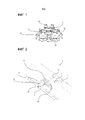
Фиг. 1 представляет собой вид в перспективе корпуса.FIG. 1 is a perspective view of a housing.
Фиг. 2 представляет собой вид в перспективе соединителя.FIG. 2 is a perspective view of the connector.
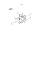
Фиг. 3 представляет собой вид в перспективе корпуса.FIG. 3 is a perspective view of the housing.
Компонентам, показанным на чертежах, присвоены следующие ссылочные позиции:The components shown in the drawings are assigned the following reference numbers:
1 - Соединитель1 - Connector
2 - Поверхность листового металла2 - Surface of sheet metal
21 - Фланец21 - Flange
22 - Канавка фланца22 - Flange groove
3 - Пластиковая поверхность3 - Plastic surface
31 - Установочный выступ31 - Mounting protrusion
32 - Пластиковый шип32 - Plastic spike
4 - Корпус4 - Case
41 - Шип корпуса41 - Thorn of the body
42 - Опорный элемент42 - Supporting element
43 - Установочное отверстие43 - Installation hole
44 - Отверстие для введения в зацепление44 - Hole for engagement
45 - Шип для соприкосновения с листовым металлом45 - Thorn for contact with sheet metal
Соединитель (1), который используется в соединениях транспортного средства, и который обеспечивает герметичность, по существу содержит:The connector (1), which is used in the joints of the vehicle, and which provides a seal, essentially contains:
- по меньшей мере одну поверхность (2) листового металла,- at least one surface (2) of the sheet metal,
- по меньшей мере один фланец (21), лежащий на поверхности (2) листового металла,- at least one flange (21) lying on the surface (2) of the sheet metal,
- по меньшей мере одну канавку (22) фланца, которая просверлена во фланце (21),- at least one groove (22) of the flange, which is drilled into the flange (21),
- по меньшей мере одну пластиковую поверхность (3), которая выполнена с возможностью расположения на поверхности (2) листового металла,- at least one plastic surface (3), which is configured to be located on the surface (2) of the sheet metal,
- по меньшей мере один установочный выступ (31), который расположен на пластиковой поверхности (3),- at least one locating protrusion (31), which is located on the plastic surface (3),
- по меньшей мере один пластиковый шип (32), который расположен на пластиковой поверхности (3),- at least one plastic spike (32), which is located on the plastic surface (3),
- по меньшей мере один корпус (4), расположенный между поверхностью (2) листового металла и пластиковой поверхностью (3),- at least one body (4) located between the surface (2) of the sheet metal and the plastic surface (3),
- по меньшей мере один шип (41) корпуса, который расположен на корпусе (4) и который вводится в канавку (22) фланца,- at least one stud (41) of the body, which is located on the body (4) and which is inserted into the groove (22) of the flange,
- по меньшей мере один опорный элемент (42), который расположен на корпусе (4) и который входит в соприкосновение с поверхностью (2) листового металла,- at least one support element (42), which is located on the body (4) and which comes into contact with the surface (2) of the sheet metal,
- по меньшей мере одно установочное отверстие (43), которое просверлено в корпусе (4), и через которое проходит установочный выступ (31),- at least one locating hole (43) which is drilled in the housing (4) and through which the locating protrusion (31) passes,
- по меньшей мере одно отверстие (44) для введения в зацепление, которое просверлено в корпусе (4) и в которое вводится пластиковый шип (32).- at least one hole (44) for engagement, which is drilled in the housing (4) and into which a plastic spike (32) is inserted.
В соединителе (1) настоящего изобретения предусмотрена поверхность (2) листового металла, которая, предпочтительно, используется в области крыши транспортного средства. Фланец (21) лежит на упомянутой поверхности (2) листового металла, предпочтительно, на ее кромке, и во фланце (21) просверлена канавка (22) фланца. Предусмотрена пластиковая поверхность (3), которая выполнена с возможностью расположения на поверхности (2) листового металла, и которая устанавливается с обеспечением ее параллельности относительно края поверхности (2) листового металла. Предусмотрена пластиковая поверхность (3), выполненная с возможностью расположения на поверхности (2) листового металла. Пластиковая поверхность (3) используется для накрывания места, в котором соединено множество поверхностей (2) листового металла. На пластиковой поверхности (3) расположен установочный выступ (31). Установочный выступ (31) выполнен в форме вертикального стержня, проходящего от пластиковой поверхности (3). На пластиковой поверхности (3) расположен пластиковый шип (32). Между поверхностью (2) листового металла и пластиковой поверхностью (3) расположен корпус (4) с обеспечением накрывания места, в котором соединяют поверхности (2) листового металла. На корпусе (4) предусмотрен шип (41) корпуса, расположенный с возможностью введения в канавку (22) фланца. К тому же, на корпусе (4) предусмотрен опорный элемент (42). Опорный элемент (42) проходит от корпуса (4) в форме вертикального стержня, входящего в соприкосновение с поверхностью (2) листового металла, и обеспечивает приложение обратной силы для прочного удерживания шипа (41) корпуса. В корпусе (4) просверлено установочное отверстие (43), и установочный выступ (31) проходит через установочное отверстие (43), фиксируя тем самым пластиковую поверхность (3). На корпусе (4) просверлено отверстие (44) для введения в зацепление, и пластиковый шип (32) проходит через это отверстие (44) для введения в зацепление. Таким образом, обеспечивается скрепление корпуса (4) и пластиковой поверхности (3) друг с другом. Таким образом, разработан соединитель (1), который обеспечивает исключение рисков протечки воды посредством разработки альтернативного соединения без просверливания отверстия в листовом металле в случаях декоративного применения пластиковой поверхности (3), которая должна быть установлена на линии торцевого соединения листового металла.In the connector (1) of the present invention, a sheet metal surface (2) is provided, which is preferably used in the region of the vehicle roof. The flange (21) lies on said surface (2) of the sheet metal, preferably at its edge, and a groove (22) of the flange is drilled in the flange (21). A plastic surface (3) is provided that is arranged to be positioned on the surface (2) of the sheet metal, and which is mounted so that it is parallel to the edge of the surface (2) of the sheet metal. A plastic surface (3) is provided that can be positioned on the surface (2) of sheet metal. The plastic surface (3) is used to cover the place where the plurality of surfaces (2) of the sheet metal are connected. On the plastic surface (3) there is a locating lug (31). The locating projection (31) is made in the form of a vertical rod extending from the plastic surface (3). On the plastic surface (3) there is a plastic spike (32). A housing (4) is located between the surface (2) of the sheet metal and the plastic surface (3) to cover the place where the surfaces (2) of the sheet metal are connected. On the body (4) there is a body spike (41) located with the possibility of insertion into the groove (22) of the flange. In addition, a support element (42) is provided on the housing (4). The support member (42) extends from the body (4) in the form of a vertical rod, which comes into contact with the surface (2) of the sheet metal, and provides a reverse force to firmly hold the tenon (41) of the body. A locating hole (43) is drilled in the housing (4), and the locating protrusion (31) passes through the locating hole (43), thereby fixing the plastic surface (3). A hole (44) is drilled on the body (4) for engagement, and a plastic spike (32) passes through this hole (44) for engagement. Thus, the body (4) and the plastic surface (3) are secured to each other. Thus, a connector (1) has been developed that eliminates the risk of water leakage by developing an alternative connection without drilling a hole in the sheet metal in cases of decorative use of a plastic surface (3), which should be installed on the end connection line of the sheet metal.
Соединитель (1) обеспечивает установку пластиковой поверхности (3), которая накрывает места, в которых поверхности (2) листового металла расположены одна поверх другой. С этой целью шип (41) корпуса, предусмотренный на корпусе (4), прикрепляется к канавке (21) фланца, и опорный элемент (42) на корпусе (4) воздействует обратной силой на поверхность, которую он удерживает, с обеспечением сохранения фиксирования корпуса (4) на поверхности листового металла. В предпочтительном варианте осуществления изобретения опорный элемент (42) представляет собой упругий элемент. В предпочтительном варианте осуществления изобретения опорный элемент (42) содержит пружину. В предпочтительном варианте осуществления изобретения опорный элемент (42) расположен с обеих противоположных сторон корпуса (4) для обеспечения устойчивости. Пластиковая поверхность (3) присоединяется к корпусу (4), который устанавливается на поверхности (2) листового металла. В корпусе (4) предусмотрено установочное отверстие (43) для прикрепления пластиковой поверхности (3), и пользователь концентрически располагает установочный выступ (31) пластиковой поверхности (3) и установочное отверстие (43) для того чтобы правильно размещать пластиковую поверхность (3). Установочный выступ (31) проходит через концентрическое установочное отверстие (43). После прохождения установочного выступа (31) через установочное отверстие (43), пластиковый шип (32) на пластиковой поверхности (3) вводится в отверстие (44) для введения в зацепление. Таким образом, разработан соединитель, который выполнен с возможностью обеспечения простого и быстрого соединения пластиковой поверхности (3) с поверхностью (2) листового металла техническим специалистом.The connector (1) provides for the installation of a plastic surface (3) that covers the places where the surfaces (2) of the sheet metal are located one on top of the other. To this end, the body spike (41) provided on the body (4) is attached to the groove (21) of the flange, and the support element (42) on the body (4) acts with a reverse force on the surface that it holds, ensuring that the body is retained. (4) on the surface of the sheet metal. In a preferred embodiment of the invention, the support member (42) is an elastic member. In a preferred embodiment of the invention, the support element (42) comprises a spring. In a preferred embodiment of the invention, a support member (42) is located on both opposite sides of the housing (4) to provide stability. The plastic surface (3) attaches to the body (4), which is mounted on the surface (2) of the sheet metal. The housing (4) is provided with a locating hole (43) for attaching the plastic surface (3), and the user concentrically positions the locating protrusion (31) of the plastic surface (3) and the locating hole (43) in order to correctly position the plastic surface (3). The locating lug (31) passes through the concentric locating hole (43). After the locating protrusion (31) has passed through the locating hole (43), the plastic spike (32) on the plastic surface (3) is inserted into the hole (44) for engagement. Thus, a connector has been developed which is adapted to provide a simple and quick connection of the plastic surface (3) to the surface (2) of the sheet metal by a technician.
В предпочтительном варианте осуществления изобретения предусмотрен по меньшей мере один шип (45) для из листового металла, который расположен на корпусе (4), для обеспечения прочного удерживания соединителя (1) на поверхности (2) листового металла. Шип (45) из листового металла предусмотрен на краях корпуса (4) для обеспечения удерживания соединителя (1) на поверхностях (2) листового металла, которые находятся в разных положениях; и он имеет меньшую по размеру форму по сравнению с шипом (41) корпуса. Однако он обращен к той же самой поверхности, что и шип (41) корпуса.In a preferred embodiment of the invention, at least one sheet metal spike (45) is provided, which is located on the housing (4), to ensure that the connector (1) is firmly held on the sheet metal surface (2). A spike (45) of sheet metal is provided on the edges of the body (4) to ensure that the connector (1) is held on the surfaces (2) of the sheet metal, which are in different positions; and it has a smaller shape compared to the body spike (41). However, it faces the same surface as the housing spike (41).
Claims (12)
Applications Claiming Priority (3)
| Application Number | Priority Date | Filing Date | Title |
|---|---|---|---|
| TR2017/13375A TR201713375A2 (en) | 2017-09-12 | 2017-09-12 | |
| TR2017/13375 | 2017-09-12 | ||
| PCT/TR2018/050467 WO2019098975A2 (en) | 2017-09-12 | 2018-09-05 | A connector |
Publications (1)
| Publication Number | Publication Date |
|---|---|
| RU2742227C1 true RU2742227C1 (en) | 2021-02-03 |
Family
ID=66397402
Family Applications (1)
| Application Number | Title | Priority Date | Filing Date |
|---|---|---|---|
| RU2020113244A RU2742227C1 (en) | 2017-09-12 | 2018-09-05 | Connector |
Country Status (6)
| Country | Link |
|---|---|
| EP (1) | EP3682123B1 (en) |
| ES (1) | ES2948985T3 (en) |
| PL (1) | PL3682123T3 (en) |
| RU (1) | RU2742227C1 (en) |
| TR (1) | TR201713375A2 (en) |
| WO (1) | WO2019098975A2 (en) |
Citations (4)
| Publication number | Priority date | Publication date | Assignee | Title |
|---|---|---|---|---|
| GB2121098B (en) * | 1982-05-21 | 1985-09-25 | Tucker Fasteners Ltd | Clip for mounting trim strips |
| FR2943106A1 (en) * | 2009-03-11 | 2010-09-17 | Rehau Sa | FIXING CLIP WITH TWO STABLE HOLDING POSITIONS FOR STICK, MOUNTED BY PUSHING PERPENDICULAR TO THE STICK |
| US8205923B2 (en) * | 2010-09-20 | 2012-06-26 | GM Global Technology Operations LLC | Retaining clip for ditch molding |
| RU2584411C2 (en) * | 2011-03-24 | 2016-05-20 | Форд Глобал Технолоджис, ЛЛК | Two-stage removable fastening clip |
Family Cites Families (4)
| Publication number | Priority date | Publication date | Assignee | Title |
|---|---|---|---|---|
| JPH081285Y2 (en) | 1991-04-18 | 1996-01-17 | 株式会社ニフコ | Mall mounting clip |
| DE19857372C1 (en) * | 1998-12-11 | 2000-07-13 | Trw Automotive Electron & Comp | Plastics holder to mount decorative trim strips to carriers at a vehicle bodywork has a holding section with sprung mounting tongues with an opening in an intermediate plate section to grip round the carrier bolt through the opening |
| US8677572B2 (en) * | 2008-06-06 | 2014-03-25 | Illinois Tool Works Inc. | Compensating position roof ditch molding retainer |
| US8955896B2 (en) | 2012-07-10 | 2015-02-17 | U.S. Farathane Corporation | Tri-extruded roof ditch molding with hard and soft components including associated fastener system and method for heat forming the roof ditch molding |
-
2017
- 2017-09-12 TR TR2017/13375A patent/TR201713375A2/tr unknown
-
2018
- 2018-09-05 PL PL18875009.5T patent/PL3682123T3/en unknown
- 2018-09-05 RU RU2020113244A patent/RU2742227C1/en active
- 2018-09-05 WO PCT/TR2018/050467 patent/WO2019098975A2/en unknown
- 2018-09-05 EP EP18875009.5A patent/EP3682123B1/en active Active
- 2018-09-05 ES ES18875009T patent/ES2948985T3/en active Active
Patent Citations (4)
| Publication number | Priority date | Publication date | Assignee | Title |
|---|---|---|---|---|
| GB2121098B (en) * | 1982-05-21 | 1985-09-25 | Tucker Fasteners Ltd | Clip for mounting trim strips |
| FR2943106A1 (en) * | 2009-03-11 | 2010-09-17 | Rehau Sa | FIXING CLIP WITH TWO STABLE HOLDING POSITIONS FOR STICK, MOUNTED BY PUSHING PERPENDICULAR TO THE STICK |
| US8205923B2 (en) * | 2010-09-20 | 2012-06-26 | GM Global Technology Operations LLC | Retaining clip for ditch molding |
| RU2584411C2 (en) * | 2011-03-24 | 2016-05-20 | Форд Глобал Технолоджис, ЛЛК | Two-stage removable fastening clip |
Also Published As
| Publication number | Publication date |
|---|---|
| TR201713375A2 (en) | 2019-03-21 |
| WO2019098975A3 (en) | 2019-08-08 |
| PL3682123T3 (en) | 2023-09-18 |
| EP3682123A2 (en) | 2020-07-22 |
| ES2948985T3 (en) | 2023-09-22 |
| WO2019098975A2 (en) | 2019-05-23 |
| EP3682123B1 (en) | 2023-04-26 |
Similar Documents
| Publication | Publication Date | Title |
|---|---|---|
| TWI613347B (en) | Grid runner to perimeter trim clip | |
| JP5538819B2 (en) | Fasteners and fastener assemblies | |
| US8875357B2 (en) | Clip | |
| KR101508883B1 (en) | Devices such as binding ceilings | |
| WO2007128070A1 (en) | Assembly including a fastening device | |
| JP2004183895A (en) | Clamping device for long object, in particular, cable tree | |
| JPS6032405Y2 (en) | Parts mounting structure | |
| JP2005121225A (en) | Fastener for fixed rib application | |
| US20120085874A1 (en) | Device for fastening a connector piece to a carrier piece and fastening arrangement having such a device | |
| KR20100045994A (en) | An integral clip of plastic material | |
| KR20190063604A (en) | Connector assembly for hose connection of hot water mat | |
| RU2742227C1 (en) | Connector | |
| CN112424424A (en) | Sheet assembly including quick clamp module | |
| JP5769529B2 (en) | Clip material for ceiling base | |
| KR200450292Y1 (en) | Seal and Connector clip comprising the same | |
| KR200476560Y1 (en) | Clamp Guide and Clamp Assembly Including The Same | |
| ES2326384T3 (en) | PROVISION FOR THE ASSEMBLY OF AN EMBELLECEDOR ON AN AUTOMOTIVE VEHICLE BODY ELEMENT. | |
| KR200477672Y1 (en) | Clamp Guide and Clamp Assembly Including The Same | |
| JPS60174318A (en) | Cowl-grille installation structure | |
| JP5559552B2 (en) | Mounting structure for vehicle lamp | |
| JPS5918916Y2 (en) | Attachment holder for molding | |
| KR0151658B1 (en) | Filter using ventilation | |
| CN111828453B (en) | Fixing device and mounting assembly comprising said fixing device | |
| JPH09303817A (en) | Piping-clamping tool in indoor machine of air conditioner | |
| KR200316132Y1 (en) | Fixing tool for curtain support bar |