RU2731477C2 - Selectively movable valves for aspiration and irrigation circuits - Google Patents
Selectively movable valves for aspiration and irrigation circuits Download PDFInfo
- Publication number
- RU2731477C2 RU2731477C2 RU2017114183A RU2017114183A RU2731477C2 RU 2731477 C2 RU2731477 C2 RU 2731477C2 RU 2017114183 A RU2017114183 A RU 2017114183A RU 2017114183 A RU2017114183 A RU 2017114183A RU 2731477 C2 RU2731477 C2 RU 2731477C2
- Authority
- RU
- Russia
- Prior art keywords
- aspiration
- line
- irrigation
- valve
- selectively
- Prior art date
Links
- 230000002262 irrigation Effects 0.000 title claims description 230
- 238000003973 irrigation Methods 0.000 title claims description 230
- 239000012530 fluid Substances 0.000 claims abstract description 54
- 238000006073 displacement reaction Methods 0.000 claims abstract description 19
- 230000000694 effects Effects 0.000 claims abstract description 5
- 230000004044 response Effects 0.000 claims abstract description 4
- 238000004891 communication Methods 0.000 claims description 35
- 230000008859 change Effects 0.000 claims description 13
- 230000002572 peristaltic effect Effects 0.000 claims description 10
- 238000005516 engineering process Methods 0.000 claims description 5
- 239000000463 material Substances 0.000 abstract description 3
- 230000005534 acoustic noise Effects 0.000 abstract description 2
- 229920001971 elastomer Polymers 0.000 abstract description 2
- 239000000806 elastomer Substances 0.000 abstract description 2
- 238000009434 installation Methods 0.000 abstract 1
- 239000000126 substance Substances 0.000 abstract 1
- 238000013461 design Methods 0.000 description 26
- 238000009423 ventilation Methods 0.000 description 18
- 238000010586 diagram Methods 0.000 description 13
- 238000000034 method Methods 0.000 description 11
- 238000001802 infusion Methods 0.000 description 10
- 238000005086 pumping Methods 0.000 description 9
- 238000001356 surgical procedure Methods 0.000 description 8
- 208000002177 Cataract Diseases 0.000 description 5
- 239000003570 air Substances 0.000 description 5
- 239000007788 liquid Substances 0.000 description 5
- 239000002699 waste material Substances 0.000 description 5
- 230000009471 action Effects 0.000 description 4
- 239000013078 crystal Substances 0.000 description 4
- 230000001276 controlling effect Effects 0.000 description 3
- 210000004087 cornea Anatomy 0.000 description 3
- 210000003128 head Anatomy 0.000 description 3
- 238000002604 ultrasonography Methods 0.000 description 3
- FAPWRFPIFSIZLT-UHFFFAOYSA-M Sodium chloride Chemical compound [Na+].[Cl-] FAPWRFPIFSIZLT-UHFFFAOYSA-M 0.000 description 2
- 239000012080 ambient air Substances 0.000 description 2
- 238000013459 approach Methods 0.000 description 2
- 238000010276 construction Methods 0.000 description 2
- 230000007246 mechanism Effects 0.000 description 2
- 238000012986 modification Methods 0.000 description 2
- 230000004048 modification Effects 0.000 description 2
- 230000001105 regulatory effect Effects 0.000 description 2
- 210000001525 retina Anatomy 0.000 description 2
- 239000011780 sodium chloride Substances 0.000 description 2
- 125000002066 L-histidyl group Chemical group [H]N1C([H])=NC(C([H])([H])[C@](C(=O)[*])([H])N([H])[H])=C1[H] 0.000 description 1
- 230000005856 abnormality Effects 0.000 description 1
- 230000001133 acceleration Effects 0.000 description 1
- 210000002159 anterior chamber Anatomy 0.000 description 1
- 230000003466 anti-cipated effect Effects 0.000 description 1
- 230000033228 biological regulation Effects 0.000 description 1
- 230000000903 blocking effect Effects 0.000 description 1
- 238000011161 development Methods 0.000 description 1
- 230000018109 developmental process Effects 0.000 description 1
- 239000013536 elastomeric material Substances 0.000 description 1
- 230000005484 gravity Effects 0.000 description 1
- 230000037361 pathway Effects 0.000 description 1
- 230000008569 process Effects 0.000 description 1
- 230000010349 pulsation Effects 0.000 description 1
- 238000011084 recovery Methods 0.000 description 1
- 210000003786 sclera Anatomy 0.000 description 1
- 239000007787 solid Substances 0.000 description 1
- 238000012546 transfer Methods 0.000 description 1
- 238000005406 washing Methods 0.000 description 1
Images


Classifications
-
- A—HUMAN NECESSITIES
- A61—MEDICAL OR VETERINARY SCIENCE; HYGIENE
- A61F—FILTERS IMPLANTABLE INTO BLOOD VESSELS; PROSTHESES; DEVICES PROVIDING PATENCY TO, OR PREVENTING COLLAPSING OF, TUBULAR STRUCTURES OF THE BODY, e.g. STENTS; ORTHOPAEDIC, NURSING OR CONTRACEPTIVE DEVICES; FOMENTATION; TREATMENT OR PROTECTION OF EYES OR EARS; BANDAGES, DRESSINGS OR ABSORBENT PADS; FIRST-AID KITS
- A61F9/00—Methods or devices for treatment of the eyes; Devices for putting-in contact lenses; Devices to correct squinting; Apparatus to guide the blind; Protective devices for the eyes, carried on the body or in the hand
- A61F9/007—Methods or devices for eye surgery
- A61F9/00736—Instruments for removal of intra-ocular material or intra-ocular injection, e.g. cataract instruments
- A61F9/00745—Instruments for removal of intra-ocular material or intra-ocular injection, e.g. cataract instruments using mechanical vibrations, e.g. ultrasonic
-
- A—HUMAN NECESSITIES
- A61—MEDICAL OR VETERINARY SCIENCE; HYGIENE
- A61M—DEVICES FOR INTRODUCING MEDIA INTO, OR ONTO, THE BODY; DEVICES FOR TRANSDUCING BODY MEDIA OR FOR TAKING MEDIA FROM THE BODY; DEVICES FOR PRODUCING OR ENDING SLEEP OR STUPOR
- A61M1/00—Suction or pumping devices for medical purposes; Devices for carrying-off, for treatment of, or for carrying-over, body-liquids; Drainage systems
- A61M1/71—Suction drainage systems
- A61M1/72—Cassettes forming partially or totally the fluid circuit
-
- A—HUMAN NECESSITIES
- A61—MEDICAL OR VETERINARY SCIENCE; HYGIENE
- A61M—DEVICES FOR INTRODUCING MEDIA INTO, OR ONTO, THE BODY; DEVICES FOR TRANSDUCING BODY MEDIA OR FOR TAKING MEDIA FROM THE BODY; DEVICES FOR PRODUCING OR ENDING SLEEP OR STUPOR
- A61M1/00—Suction or pumping devices for medical purposes; Devices for carrying-off, for treatment of, or for carrying-over, body-liquids; Drainage systems
- A61M1/71—Suction drainage systems
- A61M1/74—Suction control
- A61M1/742—Suction control by changing the size of a vent
-
- A—HUMAN NECESSITIES
- A61—MEDICAL OR VETERINARY SCIENCE; HYGIENE
- A61M—DEVICES FOR INTRODUCING MEDIA INTO, OR ONTO, THE BODY; DEVICES FOR TRANSDUCING BODY MEDIA OR FOR TAKING MEDIA FROM THE BODY; DEVICES FOR PRODUCING OR ENDING SLEEP OR STUPOR
- A61M1/00—Suction or pumping devices for medical purposes; Devices for carrying-off, for treatment of, or for carrying-over, body-liquids; Drainage systems
- A61M1/71—Suction drainage systems
- A61M1/77—Suction-irrigation systems
-
- A—HUMAN NECESSITIES
- A61—MEDICAL OR VETERINARY SCIENCE; HYGIENE
- A61M—DEVICES FOR INTRODUCING MEDIA INTO, OR ONTO, THE BODY; DEVICES FOR TRANSDUCING BODY MEDIA OR FOR TAKING MEDIA FROM THE BODY; DEVICES FOR PRODUCING OR ENDING SLEEP OR STUPOR
- A61M1/00—Suction or pumping devices for medical purposes; Devices for carrying-off, for treatment of, or for carrying-over, body-liquids; Drainage systems
- A61M1/84—Drainage tubes; Aspiration tips
-
- A—HUMAN NECESSITIES
- A61—MEDICAL OR VETERINARY SCIENCE; HYGIENE
- A61M—DEVICES FOR INTRODUCING MEDIA INTO, OR ONTO, THE BODY; DEVICES FOR TRANSDUCING BODY MEDIA OR FOR TAKING MEDIA FROM THE BODY; DEVICES FOR PRODUCING OR ENDING SLEEP OR STUPOR
- A61M3/00—Medical syringes, e.g. enemata; Irrigators
- A61M3/02—Enemata; Irrigators
- A61M3/0201—Cassettes therefor
-
- A—HUMAN NECESSITIES
- A61—MEDICAL OR VETERINARY SCIENCE; HYGIENE
- A61M—DEVICES FOR INTRODUCING MEDIA INTO, OR ONTO, THE BODY; DEVICES FOR TRANSDUCING BODY MEDIA OR FOR TAKING MEDIA FROM THE BODY; DEVICES FOR PRODUCING OR ENDING SLEEP OR STUPOR
- A61M3/00—Medical syringes, e.g. enemata; Irrigators
- A61M3/02—Enemata; Irrigators
- A61M3/0279—Cannula; Nozzles; Tips; their connection means
- A61M3/0283—Cannula; Nozzles; Tips; their connection means with at least two inner passageways, a first one for irrigating and a second for evacuating
-
- A—HUMAN NECESSITIES
- A61—MEDICAL OR VETERINARY SCIENCE; HYGIENE
- A61B—DIAGNOSIS; SURGERY; IDENTIFICATION
- A61B2217/00—General characteristics of surgical instruments
- A61B2217/002—Auxiliary appliance
- A61B2217/005—Auxiliary appliance with suction drainage system
-
- A—HUMAN NECESSITIES
- A61—MEDICAL OR VETERINARY SCIENCE; HYGIENE
- A61B—DIAGNOSIS; SURGERY; IDENTIFICATION
- A61B2217/00—General characteristics of surgical instruments
- A61B2217/002—Auxiliary appliance
- A61B2217/007—Auxiliary appliance with irrigation system
-
- A—HUMAN NECESSITIES
- A61—MEDICAL OR VETERINARY SCIENCE; HYGIENE
- A61M—DEVICES FOR INTRODUCING MEDIA INTO, OR ONTO, THE BODY; DEVICES FOR TRANSDUCING BODY MEDIA OR FOR TAKING MEDIA FROM THE BODY; DEVICES FOR PRODUCING OR ENDING SLEEP OR STUPOR
- A61M1/00—Suction or pumping devices for medical purposes; Devices for carrying-off, for treatment of, or for carrying-over, body-liquids; Drainage systems
- A61M1/71—Suction drainage systems
- A61M1/77—Suction-irrigation systems
- A61M1/774—Handpieces specially adapted for providing suction as well as irrigation, either simultaneously or independently
-
- A—HUMAN NECESSITIES
- A61—MEDICAL OR VETERINARY SCIENCE; HYGIENE
- A61M—DEVICES FOR INTRODUCING MEDIA INTO, OR ONTO, THE BODY; DEVICES FOR TRANSDUCING BODY MEDIA OR FOR TAKING MEDIA FROM THE BODY; DEVICES FOR PRODUCING OR ENDING SLEEP OR STUPOR
- A61M1/00—Suction or pumping devices for medical purposes; Devices for carrying-off, for treatment of, or for carrying-over, body-liquids; Drainage systems
- A61M1/90—Negative pressure wound therapy devices, i.e. devices for applying suction to a wound to promote healing, e.g. including a vacuum dressing
- A61M1/91—Suction aspects of the dressing
-
- A—HUMAN NECESSITIES
- A61—MEDICAL OR VETERINARY SCIENCE; HYGIENE
- A61M—DEVICES FOR INTRODUCING MEDIA INTO, OR ONTO, THE BODY; DEVICES FOR TRANSDUCING BODY MEDIA OR FOR TAKING MEDIA FROM THE BODY; DEVICES FOR PRODUCING OR ENDING SLEEP OR STUPOR
- A61M2205/00—General characteristics of the apparatus
- A61M2205/12—General characteristics of the apparatus with interchangeable cassettes forming partially or totally the fluid circuit
- A61M2205/128—General characteristics of the apparatus with interchangeable cassettes forming partially or totally the fluid circuit with incorporated valves
-
- A—HUMAN NECESSITIES
- A61—MEDICAL OR VETERINARY SCIENCE; HYGIENE
- A61M—DEVICES FOR INTRODUCING MEDIA INTO, OR ONTO, THE BODY; DEVICES FOR TRANSDUCING BODY MEDIA OR FOR TAKING MEDIA FROM THE BODY; DEVICES FOR PRODUCING OR ENDING SLEEP OR STUPOR
- A61M2210/00—Anatomical parts of the body
- A61M2210/06—Head
- A61M2210/0612—Eyes
-
- A—HUMAN NECESSITIES
- A61—MEDICAL OR VETERINARY SCIENCE; HYGIENE
- A61M—DEVICES FOR INTRODUCING MEDIA INTO, OR ONTO, THE BODY; DEVICES FOR TRANSDUCING BODY MEDIA OR FOR TAKING MEDIA FROM THE BODY; DEVICES FOR PRODUCING OR ENDING SLEEP OR STUPOR
- A61M3/00—Medical syringes, e.g. enemata; Irrigators
- A61M3/02—Enemata; Irrigators
- A61M3/0233—Enemata; Irrigators characterised by liquid supply means, e.g. from pressurised reservoirs
- A61M3/0241—Enemata; Irrigators characterised by liquid supply means, e.g. from pressurised reservoirs the liquid being supplied by gravity
-
- A—HUMAN NECESSITIES
- A61—MEDICAL OR VETERINARY SCIENCE; HYGIENE
- A61M—DEVICES FOR INTRODUCING MEDIA INTO, OR ONTO, THE BODY; DEVICES FOR TRANSDUCING BODY MEDIA OR FOR TAKING MEDIA FROM THE BODY; DEVICES FOR PRODUCING OR ENDING SLEEP OR STUPOR
- A61M3/00—Medical syringes, e.g. enemata; Irrigators
- A61M3/02—Enemata; Irrigators
- A61M3/0233—Enemata; Irrigators characterised by liquid supply means, e.g. from pressurised reservoirs
- A61M3/0254—Enemata; Irrigators characterised by liquid supply means, e.g. from pressurised reservoirs the liquid being pumped
- A61M3/0258—Enemata; Irrigators characterised by liquid supply means, e.g. from pressurised reservoirs the liquid being pumped by means of electric pumps
Landscapes
- Health & Medical Sciences (AREA)
- Heart & Thoracic Surgery (AREA)
- Life Sciences & Earth Sciences (AREA)
- Veterinary Medicine (AREA)
- Engineering & Computer Science (AREA)
- Biomedical Technology (AREA)
- Public Health (AREA)
- General Health & Medical Sciences (AREA)
- Animal Behavior & Ethology (AREA)
- Anesthesiology (AREA)
- Hematology (AREA)
- Vascular Medicine (AREA)
- Ophthalmology & Optometry (AREA)
- Surgery (AREA)
- Nuclear Medicine, Radiotherapy & Molecular Imaging (AREA)
- Pulmonology (AREA)
- External Artificial Organs (AREA)
- Surgical Instruments (AREA)
Abstract
Description
Настоящая заявка выделена из заявки RU 2014127687, имеющей приоритет согласно дате подачи первой заявки США Сер.№ 61/568,220 "Селективно перемещаемые клапаны для контуров аспирации и ирригации" от 8 декабря 2011, содержание которой включено в данное описание путем ссылки в полном объеме, как если бы целиком и полностью изложено в данном документе.This application is separated from the application RU 2014127687, which has priority according to the filing date of the first US application Ser. No. 61 / 568,220 "Selectively movable valves for suction and irrigation circuits" dated December 8, 2011, the contents of which are incorporated into this description by reference in full, as if fully and completely set forth in this document.
ОБЛАСТЬ ТЕХНИКИFIELD OF TECHNOLOGY
Настоящее изобретение в целом относится к хирургическим системам и способам. Более конкретно, настоящее изобретение относится к системам и способам для управления потоком текучей среды в контурах аспирации и/или ирригации во время хирургической операции с использованием одного или более селективно подвижных клапанов.The present invention relates generally to surgical systems and methods. More specifically, the present invention relates to systems and methods for controlling fluid flow in aspiration and / or irrigation circuits during surgery using one or more selectively movable valves.
УРОВЕНЬ ТЕХНИКИLEVEL OF TECHNOLOGY
Человеческий глаз функционирует для того, чтобы обеспечить зрение посредством пропускания света сквозь прозрачную наружную часть, называемую роговицей, и фокусировки изображения на сетчатке посредством хрусталика. Качество сфокусированного изображения зависит от многих факторов, включающих в себя размер и форму глаза, а также прозрачность роговицы и хрусталика.The human eye functions to provide vision by passing light through a transparent outer portion called the cornea and focusing the image on the retina through the lens. The quality of a focused image depends on many factors, including the size and shape of the eye, and the clarity of the cornea and lens.
В случаях, когда возраст или заболевание являются причиной того, что хрусталик становится менее прозрачным, зрение ухудшается из-за уменьшения количества света, которое может быть пропущено к сетчатке. Эта патология в хрусталике глаза является известной как катаракта. Для лечения этого состояния необходима офтальмохирургия. Более конкретно, хирургическое удаление поврежденного хрусталика и замена его искусственной интраокулярной линзой (ИОЛ).In cases where age or illness causes the lens to become less transparent, vision deteriorates due to a decrease in the amount of light that can be transmitted to the retina. This abnormality in the lens of the eye is known as cataract. Ophthalmic surgery is needed to treat this condition. More specifically, the surgical removal of the damaged lens and its replacement with an artificial intraocular lens (IOL).
Одной из известных технологий удаления катарактных хрусталиков глаза является технология факоэмульсификации. Во время этой процедуры, тонкий режущий наконечник аппарата факоэмульсификации вводят в пораженный хрусталик и осуществляют колебания при помощи ультразвука. При помощи колебаний режущий наконечник разжижает или превращает в эмульсию хрусталик таким образом, что появляется возможность аспирировать пораженный хрусталик из глаза. После удаления вставляется искусственный хрусталик.One of the known technologies for the removal of cataract lenses of the eye is the phacoemulsification technology. During this procedure, a thin cutting tip of the phacoemulsification apparatus is inserted into the affected lens and vibrated using ultrasound. By vibration, the cutting tip liquefies or emulsifies the lens so that the affected lens can be aspirated from the eye. After removal, an artificial lens is inserted.
Типичный ультразвуковой хирургический аппарат, который подходит для офтальмологических операций состоит из рукоятки с ультразвуковым приводом, прикрепленного режущего наконечника, ирригационного патрубка и электронного пульта управления. Блок рукоятки соединен с пультом управления электрическим кабелем и гибким трубопроводом. Через электрический кабель пульт изменяет уровень мощности, которая передается рукояткой к прикрепленному режущему наконечнику, а гибкий трубопровод подает ирригационную жидкость в глаз и аспирирует жидкость из глаза через блок рукоятки.A typical ultrasonic surgical device that is suitable for ophthalmic surgery consists of an ultrasound-driven handle, an attached cutting tip, an irrigation tube and an electronic control panel. The handle unit is connected to the control panel with an electric cable and a flexible pipeline. Through an electrical cable, the console changes the level of power that is transmitted from the handle to the attached cutting tip, and the flexible tubing delivers irrigation fluid to the eye and aspirates fluid from the eye through the handle block.
Операционная часть рукоятки содержит полый резонирующий стержень или излучатель, непосредственно соединенный с группой пьезоэлектрических кристаллов. Кристаллы создают необходимые ультразвуковые колебания, которые требуются для приведения в действие, как излучателя, так и прикрепленного режущего наконечника во время факоэмульсификации и управляются при помощи пульта. Узел кристалл/излучатель является закрепленным внутри полого корпуса или оболочки рукоятки. Корпус рукоятки заканчивается частью корпуса с уменьшенным диаметром, или передней конусообразной деталью, на дистальном конце корпуса. Передняя конусообразная деталь принимает в себя ирригационный патрубок. Таким же образом высверленное отверстие излучателя принимает в себя режущий наконечник. Режущий наконечник установлен таким образом, что наконечник выступает строго на предопределенное расстояние за пределы открытого конца ирригационного патрубка.The operating part of the handle contains a hollow resonating rod or emitter directly connected to a group of piezoelectric crystals. The crystals create the necessary ultrasonic vibrations that are required to drive both the emitter and the attached cutting tip during phacoemulsification and are controlled by a remote control. The crystal / emitter assembly is fixed within a hollow body or handle shell. The handle body ends with a reduced diameter body portion, or a front tapered piece, at the distal end of the body. The front tapered piece receives the irrigation tube. In the same way, the drilled hole of the radiator receives the cutting tip. The cutting tip is positioned so that the tip protrudes exactly a predetermined distance beyond the open end of the irrigation tube.
При использовании, концы режущего наконечника и ирригационного патрубка вводятся в маленький разрез заданного размера в роговице, склере, или в другом месте глаза. Режущий наконечник с помощью ультразвука совершает колебания вдоль своей продольной оси в пределах ирригационного патрубка под воздействием управляемого кристаллом ультразвукового излучателя, и посредством этого производит эмульгирование выбранной ткани в месте нахождения. Полый режущий наконечник сообщается с высверленным отверстием в излучателе, которое в свою очередь сообщается с аспирационной магистралью, проходящей от рукоятки до пульта управления. Пониженное давление или вакуумное устройство в пульте управления вытягивает или аспирирует эмульгированную ткань из глаза через открытый конец режущего наконечника, далее через режущий наконечник и отверстие излучателя, а также через аспирационную магистраль в устройство сбора материала. Аспирация эмульгированной ткани происходит при помощи промывания физиологическим раствором или ирригации, которую осуществляют в операционном поле через небольшой кольцевой зазор между внутренней поверхностью ирригационного патрубка и режущего наконечника.In use, the ends of the cutting tip and irrigation tube are inserted into a small, preset incision in the cornea, sclera, or elsewhere in the eye. The cutting tip, using ultrasound, vibrates along its longitudinal axis within the irrigation tube under the influence of a crystal-controlled ultrasonic transducer, and thereby emulsifies the selected tissue at the location. The hollow cutting tip communicates with a drilled hole in the emitter, which in turn communicates with an aspiration line extending from the handle to the control panel. The reduced pressure or vacuum device in the control panel draws or aspirates emulsified tissue from the eye through the open end of the cutting tip, then through the cutting tip and emitter opening, and through the aspiration line to the material collection device. Aspiration of the emulsified tissue occurs by washing with saline or irrigation, which is carried out in the operating field through a small annular gap between the inner surface of the irrigation nozzle and the cutting tip.
Известные аппараты факоэмульсификации также используют хирургические кассеты для того, чтобы обеспечить множество функций при витреоретинальных хирургических операциях для оказания помощи эффективному управлению ирригацией и аспирацией количества протекающей жидкости в операционное поле и из операционного поля соответственно посредством хирургического устройства. Более конкретно, кассета действует как интерфейс между хирургическим инструментарием и пациентом, а также обеспечивает ирригацию под давлением и аспирацию количества протекающей жидкости внутрь глаза и из глаза. Были использованы разнообразные насосные системы в подключении с хирургической кассетой в жидкостных системах для хирургии катаракты, в том числе системы с вытеснением положительным давлением (чаще всего перистальтические насосы) и источники аспирации на вакуумной основе. Перистальтическая система использует ряд роликов, действующих на эластомерный трубопровод для создания потока в направлении вращения, в то время как системы на вакуумной основе используют вакуумный источник, который обычно применяется к потоку аспирации через поверхность раздела жидкость-воздух.Known phacoemulsification devices also use surgical cassettes to provide a variety of functions in vitreoretinal surgery to assist in efficiently managing irrigation and aspiration of flowing fluid into and out of the operating field, respectively, through a surgical device. More specifically, the cassette acts as an interface between the surgical instrument and the patient, and also provides pressure irrigation and aspiration of the amount of fluid flowing into and out of the eye. A variety of pumping systems in connection with a surgical cassette have been used in fluid systems for cataract surgery, including positive pressure displacement systems (most commonly peristaltic pumps) and vacuum-based aspiration sources. Peristaltic systems use a series of rollers acting on an elastomeric tubing to create flow in the direction of rotation, while vacuum based systems use a vacuum source that is typically applied to aspiration flow across the liquid-air interface.
Во время хирургических операций полый резонирующий наконечник может стать окклюзированным тканью. В таком случае вакуум создается в аспирационной магистрали по ходу движения среды после окклюзии. Когда окклюзия в конце концов прорывается, этот сдерживаемый вакуум, в зависимости от уровня вакуума и величины эластичности пути аспирации, высасывает значительное количество жидкости из глаза, что в результате, соответственно, увеличивает риск опустошения или коллапса передней камеры глаза. Эту ситуацию обычно называют прорывом окклюзии.During surgery, the resonant hollow tip can become occluded by tissue. In this case, a vacuum is created in the aspiration line along the path of the medium after occlusion. When the occlusion eventually breaks, this suppressed vacuum, depending on the vacuum level and the amount of elasticity of the aspiration pathway, sucks out a significant amount of fluid from the eye, resulting in a corresponding increase in the risk of emptying or collapse of the anterior chamber of the eye. This situation is commonly referred to as occlusion breakout.
Для решения этой проблемы хирургические пульты управления выполнены с возможностью позволять регистрировать уровень вакуума при помощи датчиков на пути аспирации и ограничивать вакуум системы до предварительно заданного максимального уровня. В то время как ограничение максимального уровня вакуума, таким образом, является эффективным для того, чтобы уменьшить потенциальную величину прорыва окклюзии, такие ограничения по максимальному уровню вакуума снижают эффективность удаления хрусталика и увеличивают общее время операции. В некоторых системах звуковая индикация относительного уровня вакуума и/или вакуума, достигающего предела предустановленного пользователем выполнена таким образом, чтобы хирург смог принять соответствующие меры предосторожности.To solve this problem, surgical control panels are configured to record the vacuum level using sensors along the aspiration path and limit the system vacuum to a predetermined maximum level. While limiting the maximum vacuum level is thus effective in reducing the potential for breakthrough occlusion, such limiting the maximum vacuum level reduces the efficiency of lens removal and increases the overall operation time. In some systems, an audible indication of the relative vacuum level and / or vacuum reaching a user-preset limit is designed so that the surgeon can take appropriate precautions.
Например, в некоторых системах вакуум в большинстве случаев понижает давление под управлением хирурга для того, чтобы открыть выпускной клапан, соединяющий аспирационную магистраль с источником давления, которое поддерживается на уровне или выше атмосферного давления. В зависимости от системы, это может быть ирригационная магистраль, магистраль выпуска насоса или магистраль, соединенная с атмосферным воздухом (система выброса в атмосферу). Тем не менее, существуют некоторые проблемы с известными выпускными клапанами. Во-первых, известные выпускные клапаны выполнены с возможностью осуществлять только простое действие "включение/выключение". Например, зажатые клапаны с обжимной муфтой или эластомерные управляющие купольные клапаны обеспечивают удовлетворительный контроль включения/выключения потока текучей среды, но не демонстрируют согласованные изменяющиеся характеристики потока. Таким образом, этот тип клапана имеет очень острую кривую восстановления волны. Кроме того, конфигурация управляющих клапанов купольного типа также представляет эксплуатационные проблемы. Например, работа клапана в значительной степени зависит от эластомерного материала, который предназначен для того, чтобы получить надлежащую посадку клапана, при этом очень важной является консистенция материала. Дополнительно, потоку через клапан также могут препятствовать остатки органических веществ, если отверстие, образованное эластомером является малым. Помимо всего прочего, такая конфигурация нежелательным образом задерживает пузырьки воздуха. Использование этих типов клапанов также ограничено тем, что в связи с характером включения/выключения управления ограничением потока целый ряд клапанов должен поддерживать направление потока текучей среды от одного контура к другому.For example, in some systems, a vacuum, in most cases, lowers the pressure under the control of the surgeon in order to open the outlet valve connecting the suction line to the pressure source, which is maintained at or above atmospheric pressure. Depending on the system, this can be an irrigation line, a pump outlet line, or a line connected to ambient air (exhaust system). However, there are some problems with the known exhaust valves. First, the known outlet valves are configured to perform only a simple on / off action. For example, clamped ferrule valves or elastomeric dome control valves provide satisfactory on / off control of fluid flow, but do not exhibit consistent varying flow characteristics. Thus, this type of valve has a very sharp wave recovery curve. In addition, the configuration of the dome-type control valves also presents operational problems. For example, valve performance relies heavily on an elastomeric material for proper valve seating, with material consistency being very important. Additionally, the flow through the valve can also be impeded by organic residues if the hole formed by the elastomer is small. Among other things, this configuration traps air bubbles in an undesirable manner. The use of these types of valves is also limited in that due to the on / off nature of flow restriction control, a plurality of valves must maintain the direction of fluid flow from one loop to another.
Альтернативно, вакуум уменьшается или сбрасывается давление за счет реверсирования вращения насоса в системах вытеснения положительным давлением. Хотя является известным использование системы, имеющей двунаправленное вращение насоса для того, чтобы позволить контроль давления/уровня вакуума на основе пользовательского ввода и обратной связи от датчика давления в аспирационном контуре, но при этом такая система требует быстрого ускорения и замедления напора на выходе насоса. Это ограничивает время отклика и вызывает нежелательный акустический шум.Alternatively, the vacuum is reduced or depressurized by reversing pump rotation in positive pressure displacement systems. Although it is known to use a system having bi-directional pump rotation to allow pressure / vacuum control based on user input and feedback from a pressure sensor in the aspiration circuit, such a system requires rapid acceleration and deceleration of the pump outlet head. This limits response time and causes unwanted acoustic noise.
Известные кассеты, которые используются с пультом управления, также позволяют аспирационной магистрали быть выведенной либо в атмосферу, либо в жидкость таким образом, чтобы уменьшить или устранить вакуумную пульсацию при прорыве окклюзии. Известные уровню техники кассеты, которые имеют сообщение с атмосферой, позволяют окружающему воздуху входить в аспирационную магистраль, тем не менее, вентилирование воздуха в аспирационной магистрали изменяет жидкостную производительность системы аспирации за счет значительного увеличения эластичности пути аспирации. Повышение эластичности значительно увеличивает величину прорыва окклюзии, а также негативно влияет на быстродействие системы. Жидкостные системы сброса позволяют ирригационной текучей среде спускать лишнее давление в аспирационной магистрали, тем самым снижая какое-либо влияние на жидкостную производительность системы аспирации. При использовании более высоких разрежений аспирации кассеты, которые отводят воздух аспирационной магистрали к ирригационной магистрали, являются причиной высоких скачков давления в ирригационной магистрали. Другие системы обеспечивают отдельный источник ирригационной жидкости для вентиляции аспирационной магистрали, что требует использования двух источников ирригационной жидкости и увеличивает стоимость и сложность системы.Known cassettes that are used with a control panel also allow the aspiration line to be vented either to atmosphere or liquid in such a way as to reduce or eliminate vacuum pulsation in the event of occlusion breakthrough. The cassettes known in the art, which are in communication with the atmosphere, allow ambient air to enter the aspiration line, however, ventilating the air in the aspiration line changes the liquid performance of the aspiration system by significantly increasing the elasticity of the aspiration route. An increase in elasticity significantly increases the amount of occlusion breakthrough, and also negatively affects the speed of the system. Liquid vent systems allow the irrigation fluid to release excess pressure in the aspiration line, thereby reducing any impact on the fluid performance of the aspiration system. When using higher vacuum, aspiration cassettes that divert air from the aspiration line to the irrigation line cause high pressure surges in the irrigation line. Other systems provide a separate source of irrigation fluid for ventilation of the suction line, which requires two sources of irrigation fluid and increases the cost and complexity of the system.
КРАТКое описание СУЩНОСТИ ИЗОБРЕТЕНИЯBRIEF DESCRIPTION OF THE INVENTION
Раскрыты различные конструкции жидкостных систем. В одной, приводимой в качестве примера, конструкции предлагается, что аспирационный контур жидкостной системы избирательно регулирует аспирацию. Например, один, приводимый в качестве примера, аспирационный контур содержит аспирационную магистраль, которая функционально соединена с хирургическим инструментом, аспирационную выпускную магистраль, которая функционально соединена с емкостью для отходов; аспирационную вентиляционную магистраль, которая соединена на первом конце с аспирационной магистралью; и селективно регулируемый выпускной клапан, который функционально соединен с аспирационной вентиляционной магистралью. Регулируемый выпускной клапан селективно приводится в действие для изменения аспирационного давления внутри аспирационной магистрали. В другой, приводимой в качестве примера, конструкции регулируемый выпускной клапан выполнен как многоцелевой клапан таким образом, что изменяет аспирационное давление и селективно прерывает поток ирригационной жидкости. В еще одной, приводимой в качестве примера, конструкции регулируемый выпускной клапан выполнен как многоцелевой клапан таким образом, что изменяет аспирационное давление, а также непосредственную аспирацию либо подачей насоса и/или же вакуума источника аспирации.Various designs of fluid systems are disclosed. In one exemplary design, it is proposed that the aspiration circuit of a fluid system selectively controls aspiration. For example, one exemplary suction circuit includes an aspiration line that is operatively connected to a surgical instrument; an aspiration outlet line that is operatively connected to a waste container; an aspiration ventilation line that is connected at the first end to the aspiration line; and a selectively controlled outlet valve that is operatively connected to the aspiration ventilation line. The adjustable outlet valve is selectively actuated to vary the aspiration pressure within the aspiration line. In another exemplary design, the variable outlet valve is configured as a multipurpose valve so as to vary the aspiration pressure and selectively interrupt the flow of irrigation fluid. In yet another exemplary design, the variable outlet valve is designed as a multipurpose valve in such a way that it changes the aspiration pressure as well as direct aspiration or by pumping and / or vacuuming the aspiration source.
КРАТКОЕ ОПИСАНИЕ ЧЕРТЕЖЕЙBRIEF DESCRIPTION OF DRAWINGS
Приводимые в качестве примера варианты выполнения настоящего изобретения теперь будут описаны более подробно в качестве примера со ссылкой на прилагаемые чертежи, на которых:Exemplary embodiments of the present invention will now be described in more detail by way of example with reference to the accompanying drawings, in which:
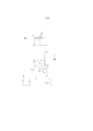
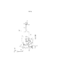
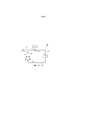
Фиг. 1 иллюстрирует вид в поперечном разрезе приводимой в качестве примера конструкции перистальтического насоса, используемого в факомашине для офтальмологических операций.FIG. 1 illustrates a cross-sectional view of an exemplary design of a peristaltic pump used in an ophthalmic phakomachine.
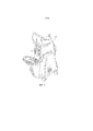
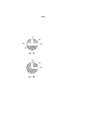
Фиг. 2 иллюстрирует вид в перспективе хирургического пульта, который использован в факомашине.FIG. 2 illustrates a perspective view of a surgical console that is used in a phakomachine.
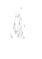
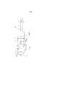
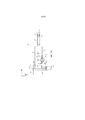
На Фиг. 3 иллюстрирована принципиальная схема приводимой в качестве примера конструкции факогидросистемы для факомашины, которая имеет селективно регулируемый выпускной клапан, расположенный между аспирационной магистралью и аспирационной выпускной магистралью.FIG. 3 illustrates a schematic diagram of an exemplary phaco-hydraulic system design for a facomachine that has a selectively adjustable outlet valve positioned between an aspiration line and an aspiration outlet line.
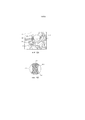
На Фиг. 4 проиллюстрирован вид в поперечном разрезе приводимой в качестве примера конфигурации регулируемого выпускного клапана для использования в факогидросистеме.FIG. 4 illustrates a cross-sectional view of an exemplary variable discharge valve configuration for use in a phaco hydraulic system.
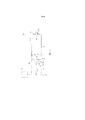
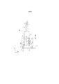
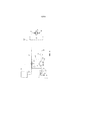
На Фиг. 5 иллюстрирована принципиальная схема приводимой в качестве примера конструкции факогидросистемы для факомашины, которая имеет селективно регулируемый выпускной клапан, расположенный между аспирационной магистралью и атмосферой.FIG. 5 illustrates a schematic diagram of an exemplary phaco-hydraulic system design for a facomachine that has a selectively controlled outlet valve positioned between the aspiration line and the atmosphere.
На Фиг. 6 иллюстрирована принципиальная схема приводимой в качестве примера конструкции факогидросистемы для факомашины, которая имеет селективно регулируемый выпускной клапан, расположенный между аспирационной магистралью и источником сброса давления.FIG. 6 illustrates a schematic diagram of an exemplary phaco-hydraulic system design for a facomachine that has a selectively controlled vent valve positioned between an aspiration line and a pressure relief source.
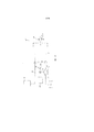
На Фиг. 7 иллюстрирована принципиальная схема приводимой в качестве примера конструкции факогидросистемы для факомашины, которая имеет селективно регулируемый выпускной клапан, расположенный между аспирационной магистралью и ирригационной магистралью.FIG. 7 illustrates a schematic diagram of an exemplary phaco-hydraulic system design for a facomachine that has a selectively controlled outlet valve positioned between the aspiration line and the irrigation line.
На Фиг. 8 иллюстрирована принципиальная схема приводимой в качестве примера конструкции факогидросистемы для факомашины, которая имеет селективно регулируемый выпускной клапан, расположенный между аспирационной магистралью и аспирационной выпускной магистралью, а также мультипозиционным ирригационным клапаном.FIG. 8 illustrates a schematic diagram of an exemplary phaco-hydraulic system design for a facomachine that has a selectively controlled outlet valve located between the aspiration line and the aspiration outlet line and a multi-position irrigation valve.
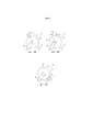
На Фиг. 9А проиллюстрирован вид в поперечном разрезе приводимого в качестве примера ирригационного клапана для использования в факогидросистеме согласно Фиг. 8.FIG. 9A illustrates a cross-sectional view of an exemplary irrigation valve for use in the phaco-hydraulic system of FIG. 8.
На Фиг. 9В проиллюстрирован вид в поперечном разрезе альтернативного варианта приводимого в качестве примера ирригационного клапана для использования в факогидросистеме.FIG. 9B illustrates a cross-sectional view of an alternate embodiment of an exemplary irrigation valve for use in a phaco-hydraulic system.
На Фиг. 10А иллюстрирована принципиальная схема приводимой в качестве примера конструкции факогидросистемы для факомашины, содержащая мультипозиционный ирригационный клапан согласно Фиг. 9В в выключенном положении.FIG. 10A illustrates a schematic diagram of an exemplary phaco-hydraulic system for a facomachine including the multi-position irrigation valve of FIG. 9V in the off position.
На Фиг. 10В иллюстрирована принципиальная схема приводимой в качестве примера конструкции факогидросистемы для факомашины, содержащая мультипозиционный ирригационный клапан согласно Фиг. 9В в положении "ирригация".FIG. 10B is a schematic diagram of an exemplary phaco-hydraulic system for a facomachine including the multi-position irrigation valve of FIG. 9B in the "irrigation" position.
На Фиг. 10С иллюстрирована принципиальная схема приводимой в качестве примера конструкции факогидросистемы для факомашины, содержащая мультипозиционный ирригационный клапан согласно Фиг. 9В в положении "шунт".FIG. 10C illustrates a schematic diagram of an exemplary phaco-hydraulic system for a facomachine comprising a multi-position irrigation valve of FIG. 9B in the shunt position.
На Фиг. 11 иллюстрирована принципиальная схема приводимой в качестве примера конструкции факогидросистемы для факомашины, которая имеет многоцелевой клапан, расположенный между аспирационной магистралью и ирригационной магистралью.FIG. 11 illustrates a schematic diagram of an exemplary phaco-hydraulic system design for a facomachine that has a multi-purpose valve positioned between an aspiration line and an irrigation line.
На Фиг. 12А проиллюстрирован частично покомпонентный вид в перспективе приводимого в качестве примера многоцелевого клапана и хирургической кассеты для использования в факогидросистеме согласно Фиг. 11.FIG. 12A illustrates a partially exploded perspective view of an exemplary multipurpose valve and surgical cassette for use in the phacohydraulic system of FIG. eleven.
На Фиг. 12В проиллюстрирован вид в поперечном разрезе многоцелевого клапана, выполненном по линии 12B-12B согласно Фиг. 12А.FIG. 12B is a cross-sectional view of the multipurpose valve taken along
На Фиг. 13 проиллюстрирована частичная принципиальная схема аспирационного контура для приводимой в качестве примера конструкции системы факогидросистемы, которая использует мультиаспирационную насосную систему с использованием как системы Вентури, так и системы перистальтического насоса.FIG. 13 is a partial schematic diagram of an aspiration loop for an exemplary phaco-hydraulic system design that uses a multi-aspiration pumping system using both a Venturi system and a peristaltic pump system.
На Фиг. 14А проиллюстрирована принципиальная схема приводимой в качестве примера конфигурации многоцелевого клапана, который находится в полностью открытом положении между аспирационной магистралью и входным отверстием насоса таким образом, что полное давление вакуума поступает через аспирационную магистраль рукоятки.FIG. 14A is a schematic diagram of an exemplary multipurpose valve configuration that is in a fully open position between the suction line and the pump inlet such that full vacuum pressure is supplied through the handle aspiration line.
На Фиг. 14В проиллюстрирована принципиальная схема многоцелевого клапана, который находится в частично открытом положении между аспирационной магистралью и аспирационной выпускной магистралью, а также между аспирационной магистралью и впускным отверстием насоса.FIG. 14B is a schematic diagram of a multipurpose valve that is in a partially open position between the aspiration line and the aspiration outlet line, and between the aspiration line and the pump inlet.
На Фиг. 14C проиллюстрирована принципиальная схема многоцелевого клапана в полностью открытом положении с резервуаром Вентури таким образом, что аспирация является направленной так же.FIG. 14C shows a schematic diagram of a multipurpose valve in a fully open position with a venturi such that aspiration is directed as well.
ПОДРОБНОЕ ОПИСАНИЕ ИЗОБРЕТЕНИЯDETAILED DESCRIPTION OF THE INVENTION
Обращаясь теперь к описанию, а также к чертежам, иллюстративные подходы к раскрытым устройствам и способам приведены подробно. Несмотря на то, что на чертежах представлены некоторые из возможных подходов, чертежи не обязательно выполнены в масштабе и некоторые признаки преувеличены, удалены или частично представлены в разрезе для того, чтобы лучше проиллюстрировать и объяснить настоящее изобретение. Дополнительно, описания, излагаемые в данном документе, не предназначены быть исчерпывающими или ограничивающими иным образом формулу изобретения для точных форм и конфигураций, которые показаны на чертежах и раскрыты в нижеследующем подробном описании.Turning now to the description, as well as to the drawings, illustrative approaches to the disclosed devices and methods are set forth in detail. Although the drawings show some of the possible approaches, the drawings are not necessarily drawn to scale and some features have been exaggerated, removed, or partially sectioned in order to better illustrate and explain the present invention. Additionally, the descriptions set forth herein are not intended to be exhaustive or otherwise limit the claims for the precise forms and configurations that are shown in the drawings and disclosed in the following detailed description.
Факомашины обычно используются в хирургии катаракты глаза для удаления пораженных катарактой хрусталиков глаза, такие машины обычно используют жидкостные системы для введения ирригационной текучей среды в операционное поле, а также обеспечивают аспирацию из операционного поля для того, чтобы удалить эмульгированную ткань. В некоторых известных системах используется система вытеснения положительным давлением, такая как насос, для того чтобы обеспечить соответствующую аспирацию. Согласно Фиг. 1 показана приводимая в качестве примера конструкция насоса 20 для аппарата факоэмульсификации. Насос 20 состоит из двигателя насоса 22 и роликовой головки 24, содержащей один или более роликов 26. Насос 20 используется в сочетании с кассетой 28, которая имеет эластомерный лист 30, прикрепленный на внешней стороне относительно твердого корпуса или основания 32. Электродвигатель насоса 22 представляет собой шаговый двигатель или серводвигатель постоянного тока. Роликовая головка 24 прикреплена к валу 34 двигателя насоса 22 таким образом, что двигатель насоса 22 вращает роликовую головку 24 в плоскости, которая является перпендикулярной к оси А-А вала 34. Вал 34 также содержит датчик углового положения вала 36. Facomachines are commonly used in eye cataract surgery to remove cataract-affected lenses of the eye, such machines typically use fluid systems to inject irrigation fluid into the surgical site and also provide aspiration from the surgical site to remove emulsified tissue. Some prior art systems use a positive pressure displacement system, such as a pump, to provide adequate aspiration. Referring to FIG. 1 shows an exemplary construction of a
Лист 30 кассеты 28 содержит канал для жидкости 38, который сформирован в нем, канал 38 выполнен таким образом, что имеет плоскую и дугообразную форму (в плоскости). Канал для жидкости 38 имеет радиус, приближенный к роликам 26 по окружности вала 34.The
Кассета 28 предназначена для установки в кассетоприемник 36 пульта управления 40 (как показано на Фигуре 2). Кассета 28 функционально соединена пультом управления 40 с рукояткой 42 (приводимая в качестве примера схематическая конструкция рукоятки 42 показана на Фигуре 3). Рукоятка 42 содержит инфузионный патрубок 44 и элемент наконечника 46, в соответствии с чем элемент наконечника 46 расположен коаксиально внутри инфузионного патрубка 44. Элемент наконечника 46 выполнен для введения в глаз 47. Инфузионный патрубок 44 позволяет ирригацию струей текучей среды из пульта управления 40 и/или кассеты 28 внутрь глаза. Аспирационную текучую среду также выводят через просвет внутреннего канала элемента наконечника 46 с пультом управления 40 и кассетой 28, которые обеспечивают аспирацию/вакуум до элемента наконечника 46. В совокупности, ирригационная и аспирационная функции аппарата факоэмульсификации 10 настоящим называются факогидросистемой 11.
Теперь согласно Фиг. 3, приводимая в качестве примера система факогидросистема 11 будет описана для использования с системой вытеснения положительным давлением (например, насосом 20). Инфузионный патрубок 44 рукоятки 42 соединен с источником ирригации 48, который содержит ирригационную жидкость, при помощи соответствующего трубопровода (то есть, ирригационной магистралью 50). В одной из приводимой в качестве примера конструкции, источник ирригации 48 представляет собой источник ирригации, находящийся под давлением (например, пакет с ирригационной текучей средой, которая селективно сжимается для нагнетания ирригационной текучей среды в ирригационную магистраль подачи). Элемент наконечника 46 соединен с входным всасывающим каналом 53 насоса, такого как насос 20, при помощи соответствующего трубопровода (то есть, аспирационной магистралью 52).Now referring to FIG. 3, an
Аспирационная выпускная магистраль 54 тянется от насоса 20. В одной, приводимой в качестве примера конструкции, аспирационная выпускная магистраль 54 соединена по текучей среде с резервуаром 56 дренажной магистрали. Резервуар 56 также дренируется в необязательный дренажный пакет 58. Альтернативно, как показано пунктиром, выпускная магистраль 54' является гидравлически соединенной непосредственно с дренажным пакетом 58.An
Аспирационная вентиляционная магистраль 60 соединена гидравлически с аспирационной магистралью 52 и аспирационной выпускной магистралью 54. Вентиляционная магистраль 60 выполнена в виде перепускного контура. Выпускной клапан 62, как будет обсуждаться более подробно ниже, гидравлически соединен с аспирационной вентиляционной магистралью 60 с возможностью селективно регулировать аспирационное давление внутри аспирационной магистрали 52. Датчик давления 63 также находится в сообщении с возможностью переноса текучей среды с аспирационной магистралью 52 для того, чтобы регистрировать давление внутри аспирационной магистрали 52. Датчик давления 63 также функционально соединен с системой управления в пульте управления 40. Система управления выполнена с возможностью обеспечить предварительно заданные уровни аспирационного давления для гидросистемы 11, как будет разъяснено ниже более подробно.The
Как описано выше, источник ирригации 48, который находится под давлением, соединен гидравлически с рукояткой 42 посредством ирригационной магистрали 50. Ирригационный клапан 64 соединен гидравлически и расположен между ирригационной магистралью 50 и инфузионным патрубком 44. Ирригационный клапан 64 обеспечивает управление селективным включением/выключением ирригационной текучей среды в ирригационной магистрали 50.As described above, the
Выпускной клапан 62 выполнен с возможностью обеспечивать изменение размера отверстия в вентиляционной магистрали 60 с целью селективной регулировки аспирации в аспирационной магистрали 52. Более конкретно, использование регулируемого выпускного клапана 62 дает возможность однонаправленному вращению насоса 20 в первом направлении для генерирования потока/вакуума, в то же время позволяя действовать механизму для динамического управления аспирационного давления в рукоятке 42. В одном приводимом примере выпускной клапан 62 выполнен как многопозиционный поворотный тип клапана, с возможностью допускать предсказуемое и точное управление размером отверстия на основе углового положения выпускного клапана 62 в вентиляционной магистрали 60.The
Приводимая в качестве примера конфигурация выпускного клапана 62 показана на Фиг. 4. На Фиг. 4, в одной приводимой в качестве примера конфигурации, многопозиционный выпускной клапан 62 содержит канал 66, определенного посредством первого и второго отверстий 68 и 69. Несмотря на то, что канал 66 показан на Фиг. 4 с первым отверстием 68 и вторым отверстием 69 одинакового размера, следует понимать, что канал 66 может быть выполнен с изменяющимся размером. Например, первое 68 и второе 69 отверстия выполнены с диаметром, который является большим, чем центральная часть канала 66 таким образом, что первое и второе отверстия 68 и 69 расширяются наружу по направлению к периферии 70 выпускного клапана 62.An exemplary configuration of the
При работе выпускной клапан 62 является селективно вращающимся в аспирационном контуре таким образом, что угловое положение канала 68 является селективно перемещающимся в вентиляционной магистрали 60. Такое движение полностью открывает, частично закрывает и/или полностью закрывает первое и второе отверстия 68 и 69 с возможностью селективно регулировать давление аспирации внутри аспирационной магистрали 52.In operation, the
Датчик давления 63 функционально соединен с системой управления, установленной в пульте управления 40. Датчик давления 63 обнаруживает и передает изменения давления в аспирационной магистрали 52 во время работы факомашины. В одной, приводимой в качестве примера конфигурации, пороговые значение заданного давления установлены в системе управления таким образом, что когда показания давления датчика давления 63 превышают эти пороговые значения, система управления селективно изменяет давление внутри аспирационной магистрали 52. Например, если датчик давления 63 регистрирует, что аспирационное давление превышает пороговое значение заданного давления, пульт управления 40 вызывает перемещение выпускного клапана 62 в вентиляционной магистрали 60 на заранее определенную величину для того, чтобы позволить удаление воздуха из аспирационной магистрали 52, достаточное для понижения давления аспирации ниже заданного порогового значения. Таким образом, датчик давления 63, выпускной клапан 62 и система управления взаимодействуют для того, чтобы позволить в режиме реального времени изменение аспирации в аспирационной магистрали 52, что позволяет достичь более высокого максимального уровня аспирации, которое будет применяться, но при этом обеспечивается эффективное уменьшение прорывов окклюзии. The
Например, согласно Фиг. 3, канал 66 выпускного клапана 62 расположен таким образом, что первое и второе отверстия 68 и 69 являются расположенными со смещением относительно оси вентиляционной магистрали 60. В этом положении выпускной клапан 62 находится в положении "полностью закрыто", при этом происходит блокирование вентиляционной магистрали 60 и обеспечивается свободный поток аспирационного давления к аспирационной магистрали 52. Если датчик давления 63 регистрирует, что аспирационное давление возросло внутри аспирационной магистрали 52 выше уровня порогового значения, то выпускной клапан 62 селективно перемещается на заданную величину с возможностью переместить первое и второе отверстия 68 и 69 в по меньшей мере частичное выравнивание, в результате чего происходит частичное открытие аспирационной выпускной магистрали 54/54’. Это действие быстро и эффективно приводит аспирационное давление внутри аспирационной магистрали 52 к предопределенной приемлемой величине, не требуя при этом реверсирования насоса. Тем не менее, следует понимать, что благодаря конфигурации канала 66 путем селективного движения выпускного клапана 62 может быть достигнуто множество уровней аспирационного давления.For example, referring to FIG. 3, the
Выпускной клапан 62 функционально соединен с силовым приводом, например электродвигателем 71, который имеет датчик углового положения (такой как датчик 36). В одном из таких приводимых примеров двигатель 71 представляет собой шаговый двигатель. Когда датчик давления 63 регистрирует, что аспирационное давление превышает пороговое значение заданного давления, блок управления автоматически приводит в движение двигатель 71 для того, чтобы произвести поворот выпускного клапана 62 в заранее предопределенное угловое положение для того, чтобы быстро изменить аспирационное давление внутри аспирационной магистрали 52. Дополнительно, блок управления, который взаимодействует с датчиком давления, расположенным в ирригационной магистрали 50, выполнен с возможностью обнаружения и минимизирования возникновение прорыва окклюзии. В частности, выпускной клапан 62 автоматически поворачивается двигателем 71 для понижения аспирационного давления в аспирационной магистрали 52. Эта функция работает для того, чтобы уменьшить эффект после прорыва окклюзии. Вследствие того, что выпускной клапан 62 позволяет селективное и динамическое управление уровнями аспирации в аспирационной магистрали 52, уровни вакуума являются легко регулируемыми для предпочтений пользователя, и тем самым обеспечивается более быстрое и более эффективное удаление хрусталика.The
Теперь согласно Фиг. 5, показаны компоненты приводимой в качестве примера альтернативной факогидросистемы 100 для использования с насосной системой вытеснения положительным давлением. Факогидросистема 100 содержит многие из тех же компонентов, какие показаны и описаны выше со ссылкой на Фигуру 3. Соответственно, аналогичным компонентам были даны те же ссылочные номера. Для описания этих компонентов делается ссылка на рассмотренное выше со ссылкой на Фиг. 3.Now referring to FIG. 5, components of an exemplary alternative phaco-
В факогидросистеме 100 аспирационная выпускная магистраль 54’ тянется от насоса 20 и соединена по текучей среде с дренажным пакетом 58. Альтернативно, как показано на Фиг. 3, факогидросистема 100 содержит выпускную магистраль 54, которая является соединенной по текучей среде с резервуаром дренажной магистрали.In the phaco-
Аспирационная вентиляционная магистраль 160 соединена по текучей среде между аспирационной магистралью 52 и атмосферой 102. Регулируемый выпускной клапан 62, соединен по текучей среде с аспирационной вентиляционной магистралью 160 с возможностью селективно регулировать аспирационное давление внутри аспирационной магистрали 52. Датчик давления 63 также находится в сообщении с возможностью переноса текучей среды с аспирационной магистралью 52.The
Как описано выше, выпускной клапан 62 выполнен с возможностью обеспечивать изменение размера отверстия для того, чтобы селективно регулировать вакуум, посредством этого позволяется однонаправленное вращение насоса 20 для генерирования потока/вакуума, при этом достигается возможность селективно регулировать вакуум/аспирацию для рукоятки 42 на основе углового положения выпускного клапана 62. Выпускной клапан 62 выполнен с возможностью обеспечивать селективное вращение с целью динамической регулировки аспирации в аспирационной магистрали 52.As described above, the
Как описано выше, в эксплуатации, датчик давления 63 является функционально соединенным с системой управления, установленной в пульте управления 40. Датчик давления 63 обнаруживает и передает изменения давления в аспирационной магистрали 52 во время работы факомашины. В одной, приводимой в качестве примера конфигурации, предварительно заданные пороговые значения давления устанавливается пользователями в системе управления. Соответственно, когда датчик давления 63 обнаруживает уровень аспирационного давления, который превышает предварительно установленные пороговые значения, система управления приводит в движение выпускной клапан 62 в соответствии с предварительно установленной величиной для того, чтобы уменьшить аспирационное давление внутри аспирационной магистрали 52 путем расположения канала 66 в выпускном клапане 62 в, по меньшей мере, частичной связи с атмосферой 102. Следует также понимать, что выпускной клапан 62 полностью открывается в атмосферу 102 для эффективной полной вентиляции аспирационной магистрали 52. Следует также понимать, что выпускной клапан 62 селективно движется для полного закрытия вентиляционной магистрали 160 в атмосферу 102, таким образом эффективно обеспечивается полный вакуум/аспирационное давление в аспирационной магистрали 52 до элемента наконечника 46. Движение выпускного клапана 62 для селективной регулировки аспирационного давления внутри аспирационной магистрали 52 осуществляется либо вручную (например, селективной работой педальным переключателем на основе предшествующих пользовательских настроек) или же автоматически с помощью двигателя 71, который функционально соединен с системой управления.As described above, in operation, the
Теперь согласно Фиг. 6, показаны компоненты другой приводимой в качестве примера альтернативной факогидросистемы 200 для использования с насосной системой вытеснения положительным давлением. Факогидросистема 200 содержит многие из тех же компонентов, какие показаны и описаны выше со ссылкой на Фиг. 3 и 5. Соответственно, аналогичным компонентам были даны те же ссылочные номера. Для подробного описания этих компонентов делается ссылка на рассмотренное выше со ссылкой на Фиг. 3.Now referring to FIG. 6, components of another exemplary alternative phaco-
Аспирационная вентиляционная магистраль 260 соединена по текучей среде между аспирационной магистралью 52 и источником сброса давления 202. Примеры применяемых источников сброса давления содержат, но не ограничиваются ими, жидкость под давлением или физиологический раствор. Регулируемый выпускной клапан 62, соединен по текучей среде с аспирационной вентиляционной магистралью 260 с возможностью селективно регулировать аспирационное давление внутри аспирационной магистрали 52. Датчик давления 63 также находится в сообщении с возможностью переноса текучей среды с аспирационной магистралью 52.The
Выпускной клапан 62 выполнен с возможностью обеспечивать изменение размера отверстия для того, чтобы селективно регулировать вакуум, посредством этого позволяется однонаправленное вращение насоса 20 в первом направлении для генерирования потока/вакуума, при этом достигается возможность селективно регулировать вакуум/аспирацию для рукоятки 42 на основе углового положения выпускного клапана 62.The
Датчик давления 63 функционально соединен с системой управления, установленной в пульте управления 40 и регистрирует, а также извещает об изменениях давления в аспирационной магистрали 52 во время работы факомашины. В одной, приводимой в качестве примера конфигурации, пороговые значение заданного давления установлены в системе управления таким образом, что когда показания давления датчика давления 63 превышают эти пороговые значения, выпускной клапан 62 осуществляет перемещение на предопределенную величину для того, чтобы уменьшить аспирационное давление внутри аспирационной магистрали 52. Это достигается путем расположения канала 66 в выпускном клапане 62 в, по меньшей мере, частичном сообщении с источником сброса давления 202, таким образом происходит открытие вентиляционной магистрали 260 и пропускание текучей среды, которая находится под давлением (например) в аспирационную магистраль 52. Двигатель 71 функционально соединен с выпускным клапаном 62 для автоматического перемещения выпускного клапана 62 на заранее определенную величину для того, чтобы автоматически регулировать уровень давления вакуума/аспирации в аспирационной магистрали 52 на основе информации, которая получена от датчика 63. Следует также понимать, что выпускной клапан 62 полностью открывается в источник сброса давления 202 для эффективного инвертирования аспирационного давления аспирационной магистрали 52 без необходимости внезапного прекращения работы насоса 20. Альтернативно, также следует понимать, что выпускной клапан 62 полностью закрывается, то есть канал 66 располагается полностью со смещением относительно оси с вентиляционной магистралью 260 таким образом, что источник сброса давления 202 не находится в сообщении с вентиляционной магистралью 260. Эта конфигурация эффективно обеспечивает полное давление вакуума/аспирации в аспирационной магистрали 52 до элемента наконечника 46.The
Теперь согласно Фиг. 7, показаны компоненты приводимой в качестве примера уже другой альтернативной факогидросистемы 300 для использования с насосной системой вытеснения положительным давлением. Факогидросистема 300 содержит многие из тех же компонентов, какие показаны и описаны выше со ссылкой на Фиг. 3 и 5-6. Соответственно, аналогичным компонентам были даны те же ссылочные номера. Для подробного описания этих компонентов делается ссылка на рассмотренное выше со ссылкой на Фиг. 3.Now referring to FIG. 7, the components of an exemplary already another alternative phaco-
Аспирационная вентиляционная магистраль 360 соединена по текучей среде между аспирационной магистралью 52 и ирригационной магистралью 50. Регулируемый выпускной клапан 62, соединен по текучей среде с аспирационной вентиляционной магистралью 360 с возможностью селективно регулировать аспирационное давление внутри аспирационной магистрали 52. Датчик давления 63 также находится в сообщении с возможностью переноса текучей среды с аспирационной магистралью 52.The
Выпускной клапан 62 выполнен с возможностью обеспечивать изменение размера отверстия для того, чтобы селективно регулировать вакуум, посредством этого позволяется непрерывное однонаправленное вращение насоса 20 в первом направлении для генерирования потока/вакуума, при этом достигается возможность селективно регулировать вакуум/аспирацию для рукоятки 42 на основе углового положения выпускного клапана 62.The
Датчик давления 63 функционально соединен с системой управления, установленной в пульте управления 40 и регистрирует, а также извещает об изменениях давления в аспирационной магистрали 52 во время работы факомашины. В одной, приводимой в качестве примера конфигурации, пороговые значение заданного давления установлены в системе управления таким образом, что когда показания давления датчика давления 63 превышают эти пороговые значения, выпускной клапан 62 осуществляет селективное перемещение на предопределенную величину для того, чтобы уменьшить, например, аспирационное давление внутри аспирационной магистрали 52. Например, канал 66 в выпускном клапане 62 перемещается с возможностью быть, по меньшей мере, частично соосным с вентиляционной магистралью 360, и посредством этого происходит расположение аспирационной магистрали 52 в, по меньшей мере, частичном сообщении с ирригационной магистралью 50 на предопределенную величину для того, чтобы автоматически регулировать уровень давления вакуума/аспирации в аспирационной магистрали 52 на основе информации, полученной от датчика 63. Следует также понимать, что выпускной клапан 62 полностью открывается в ирригационную магистраль 50 для эффективного инвертирования аспирационного давления в аспирационной магистрали 52. Альтернативно, следует также понимать, что выпускной клапан 62 расположен таким образом, что полностью закрывает ирригационную магистраль 50, и посредством этого эффективно обеспечивается полное давление вакуум/аспирации в аспирационной магистрали 52 до элемента наконечника 46. В такой конфигурации, канал 66 является полностью соосным с вентиляционной магистралью 360.The
Теперь согласно Фиг. 8, показаны компоненты приводимой в качестве примера еще другой альтернативной факогидросистемы 400 для использования с насосной системой вытеснения положительным давлением. Факогидросистема 400 содержит многие из тех же компонентов, какие показаны и описаны выше со ссылкой на Фигуры 3 и 5-7.Now referring to FIG. 8, the components of an exemplary yet other alternative phaco-
Факогидросистема 400 содержит инфузионный патрубок 44 рукоятки 42, которые соединены с источником ирригации 448 при помощи ирригационной магистрали 50. Факогидросистема 400 также содержит мультипозиционный ирригационный клапан 464, который расположен в трехходовом соединении и соединен по текучей среде с ирригационной магистралью подачи 473, ирригационной магистралью 50 и шунтирующей магистралью 476. Датчик давления ирригационной магистрали 475 расположен в ирригационной магистрали 50 между шунтирующей магистралью 476 и инфузионным патрубком 42. Рукоятка 42 также снабжена датчиком давления рукоятки 443.
Несмотря на то, что источник ирригации 448 представляет собой любой соответствующий источник ирригации, в одной, приводимой в качестве примера, конструкции источник ирригации 448 находится под давлением. Более конкретно, предусмотрено, что ирригационный пакет 449 расположен напротив платформы 451 и прижимающее усилие, которое показано стрелками 453, прикладывается к ирригационному пакету 449 с возможностью вызвать инфузию жидкости из ирригационного пакета 449 в ирригационную магистраль подачи 473. Также предполагаются другие жидкостные системы, находящиеся под давлением.While
Элемент наконечника 46 соединен с входным всасывающим каналом 53 перистальтического насоса 420 при помощи аспирационной магистрали 52. Несмотря на то, что может быть использована любая соответствующая конструкция насоса, в одной приводимой в качестве примера конфигурации, насос 420 представляет собой насос, такой как описано в заявке на патент США № 20100286651, озаглавленной "Многократно сегментированный перистальтический насос и кассета" или насос так, как описано в патенте США № 6962488, озаглавленном "Хирургическая кассета, содержащая датчик давления аспирации, содержание которых включены в качестве ссылки во всей их полноте. Аспирационная выпускная магистраль 54 тянется от насоса 420 и соединена по текучей среде с выпускным резервуаром 456. Выпускной резервуар 456 соединен по текучей среде с дренажным пакетом 58.
Аспирационная вентиляционная магистраль 460 соединена по текучей среде между аспирационной магистралью 52 и выпускным резервуаром 456 таким образом, что представляет собой перепускной канал насоса 420. Регулируемый выпускной клапан 62, соединен по текучей среде с аспирационной вентиляционной магистралью 460 с возможностью селективно регулировать аспирационное давление внутри аспирационной магистрали 52. Датчик давления аспирации 63 также находится в сообщении с возможностью переноса текучей среды с аспирационной магистралью 52. Выпускной клапан 62 выполнен с возможностью обеспечивать изменение размера отверстия в вентиляционной магистрали 460 для того, чтобы селективно регулировать вакуум, и посредством этого позволяется однонаправленное вращение насоса 420 в первом направлении для генерирования потока/вакуума, при этом достигается возможность селективно регулировать вакуум/аспирацию для рукоятки 42 на основе углового положения выпускного клапана 62.The
В процессе эксплуатации датчик давления 63 является функционально соединенным с системой управления, установленной в пульте управления 40. Датчик давления 63 обнаруживает и передает изменения давления в аспирационной магистрали 52 во время работы факомашины. В одной, приводимой в качестве примера конфигурации, пороговые значение заданного давления установлены в системе управления таким образом, что когда показания давления датчика давления 63 превышают эти пороговые значения, выпускной клапан 62 осуществляет селективное перемещение на предопределенную величину для того, чтобы уменьшить аспирационное давление внутри аспирационной магистрали 52. Это достигается путем расположения канала 66 в выпускном клапане 62 в, по меньшей мере, частичном сообщении с вентиляционной магистралью 460. Поскольку вентиляционная магистраль 460 функционально соединена с выпускным резервуаром 456, частичное сообщение канала 66 с вентиляционной магистралью 460 эффективно снижает аспирационное давление внутри аспирационной магистрали 52. Движение выпускного клапана 62 совершается посредством двигателя 71, который соединен с выпускным клапаном 62. Более конкретно, двигатель 71 выполнен с возможностью автоматически перемещать выпускной клапан 62 на заранее определенную величину для того, чтобы автоматически регулировать уровень давления вакуума/аспирации в аспирационной магистрали 52 на основе информации, которая получена от датчика 63. Следует также понимать, что выпускной клапан 62 ориентирован в полностью открытом положении для полного снижения давления в аспирационной магистрали до выпускного резервуара 456 для того, чтобы эффективно закрыть входной всасывающий канал 53 насоса 420. Альтернативно, следует также понимать, что выпускной клапан 62 является полностью закрытым, то есть, таким образом, что канал 66 находится со смещением относительно оси с вентиляционной магистралью 460, тем самым закрывая выпускной резервуар 456 для аспирационной магистрали 52, и благодаря этому эффективно обеспечивается полное давление вакуума/аспирации в аспирационной магистрали 52 до элемента наконечника 46.During operation, the
Как описано выше, факогидросистема 400 также содержит мультипозиционный ирригационный клапан 464, который расположен в трехходовом соединении и соединен по текучей среде с ирригационной магистралью подачи 473, ирригационной магистралью 50 и шунтирующей магистралью 476. Как объясняется в дополнительных деталях ниже, ирригационный клапан 464 выполнен в виде поворотного клапана, который функционально расположен с возможностью селективно управлять ирригацией в факогидросистеме 400. Как показано на Фигуре 9А, в одной приводимой в качестве примера конструкции, мультипозиционный ирригационный клапан 464 содержит перекрещивающуюся конфигурацию канала 474. Более конкретно, канал 474 включает в себя первый отвод 474А, второй отвод 474B и третий отвод 474C. Несмотря на то, что они показаны как имеющие конфигурацию Т-образной формы, следует понимать, что может быть использована другая пересекающаяся конфигурация в зависимости от конфигурации различных магистралей текучей среды в гидросистеме 400.As described above, the phaco-
В процессе работы, как показано на Фиг. 8, когда ирригационный клапан 464 ориентирован таким образом, что первый отвод 474A является полностью соосным ирригационной магистрали подачи 473 и третий отвод 474B является полностью соосным ирригационной магистрали 50, но второй отвод 474C ориентирован со смещением относительно оси с шунтирующей магистралью 476, нормальный, полный ирригационный поток снабжает ирригационную магистраль 50. Тем не менее, для того, чтобы заправить ирригационный подвод 448 перед пуском факогидросистемы 400, ирригационный клапан 464 селективно поворачивается таким образом, что первый отвод 474A является полностью соосным шунтирующей магистрали 476 и третий отвод 474C является полностью соосным ирригационной магистрали подачи 473. Соответственно, когда факогидросистема 400 работает, текучая среда из источника ирригации 448 направляется в дренажный пакет 58. Для заливки ирригационного датчика давления 475 ирригационный клапан 464 селективно поворачивается таким образом, что второй отвод 474B является полностью соосным шунтирующей магистрали 476, а третий отвод 474C является полностью соосным ирригационной магистрали 50.During operation, as shown in FIG. 8 when the
В то время как различные отводы ирригационного клапана 464, показанные на Фиг. 8, были описаны в работе с возможностью они были полностью на одной оси либо с ирригационной магистралью 50, шунтирующей магистралью 476 и ирригационной магистралью подачи 473, следует также понимать, что отводам 474a-474c нет необходимости полностью находиться соосно соответствующим магистралям 50, 476, и 473. В самом деле, ирригационный клапан 464 выполнен с возможностью селективного расположения с возможностью эффективно регулировать количество жидкости, которое будет подано к глазу 47. Действительно, у некоторых пациентов полный поток ирригации (как показано на Фиг. 8) может привести к дискомфорту пациента, в то время как регулируемое отверстие, при помощи которого определенные отводы ирригационного клапана 464 располагаются в различных угловых положениях по отношению к ирригационной магистрали 50, является желательным. Таким образом, ирригационный клапан 464 также выполнен аналогично выпускному клапану 62 для регулирования подачи ирригации.While the various branches of the
Другая альтернативная конфигурация для мультипозиционного ирригационного клапана показана на Фиг. 9B. В этой конструкции представлен мультипозиционный ирригационный клапан 464', который имеет Г-образный проход, сформированный в нем. Мультипозиционный ирригационный клапан 464’ содержит первый отвод 474A’ и второй отвод 474B’. Использование мультипозиционного ирригационного клапана 464' будет описано ниже со ссылкой на Фиг. 10А-10С.Another alternative configuration for a multi-position irrigation valve is shown in FIG. 9B. This design presents a multi-position irrigation valve 464 'that has an L-shaped passage formed therein. The multi-position irrigation valve 464 'comprises a first branch 474A' and a second branch 474B '. The use of the multi-position irrigation valve 464 'will be described below with reference to FIG. 10A-10C.
Ссылаясь на Фиг. 10А-10С, показаны компоненты приводимой в качестве примера другой альтернативной факогидросистемы 400’ для использования с насосной системой вытеснения положительным давлением. Факогидросистема 400’ содержит многие из тех же компонентов, какие показаны и описаны выше со ссылкой на Фигуры 3 и 5-8. В некоторых вариантах выполнения изобретения компоненты внутри пунктирного прямоугольника, по меньшей мере, частично включены в пневмогидросистему кассеты, которая выполнена с возможностью прикрепления к хирургическому пульту управления.Referring to FIG. 10A-10C, components of an exemplary other alternative phaco-hydraulic system 400 'are shown for use with a positive pressure displacement pumping system. Fakohydrosystem 400 'contains many of the same components as shown and described above with reference to Figures 3 and 5-8. In some embodiments of the invention, the components within the dashed rectangle are at least partially included in the pneumatic hydraulic system of the cassette, which is configured to be attached to the surgical control panel.
Факогидросистема 400’ содержит инфузионный патрубок 44 рукоятки 42, которые соединены с источником ирригации 448 при помощи ирригационной магистрали 50. Мультипозиционный ирригационный клапан 464’ расположен в трехходовом соединении и соединен по текучей среде с ирригационной магистралью подачи 473, ирригационной магистралью 50 и шунтирующей магистралью 476. Датчик давления ирригационной магистрали 475 расположен в ирригационной магистрали 50 между источником ирригации 448 и рукояткой 42. Несмотря на то, что источником ирригации 448 может быть любой подходящий источник ирригации, в одной, приводимой в качестве примера, конструкции источник ирригации 448 содержит ирригационный контейнер, в котором используется сила тяжести для того, чтобы производить инфузию жидкости из ирригационного контейнера в ирригационную магистраль подачи 473.The phacohydrosystem 400 'comprises an
Мультипозиционный ирригационный клапан 464’ выполнен в виде поворотного клапана, который функционально расположен с возможностью селективно управлять ирригацией в факогидросистеме 400’. Таким образом, в процессе работы, как показано на Фигуре 10А, когда ирригационный клапан 464’ ориентирован таким образом, что первый отвод 474A’ устанавливается соосно ирригационной магистрали 50, а второй отвод 474B’ ориентирован со смещением относительно оси с ирригационной магистралью подачи 473 и шунтирующей магистралью 476, подача ирригационной жидкости в ирригационную магистраль 50 не происходит.The multi-position irrigation valve 464 'is in the form of a rotary valve, which is functionally positioned to selectively control irrigation in the phaco-hydraulic system 400'. Thus, in operation, as shown in Figure 10A, when the irrigation valve 464 'is oriented such that the first branch 474A' is aligned with the
Теперь согласно Фиг. 10B, для подачи ирригации к рукоятке 42 ирригационный клапан 464' селективно поворачивается таким образом, что первый отвод 474A', по меньшей мере, частично устанавливается соосно с ирригационной магистралью подачи 473, а второй отвод 474B', по меньшей мере, частично устанавливается соосно с ирригационной магистралью 50. Соответственно, жидкость из источника ирригации 448 направляется через ирригационную магистраль подачи 473 в ирригационную магистраль 50 через ирригационный клапан 464’ к рукоятке 42. Как и в случае с ирригационным клапаном 464, желательно селективно расположить первый и второй отводы 474A’ и 474B’ с возможностью эффективно регулировать количество жидкости, которое будет подаваться к глазу 47. Таким образом, предполагается, что ирригационная магистраль 50 регулирует отверстие с ирригационной магистралью подачи 473, в результате чего первый и второй отводы 474A’ и 474B’ ирригационного клапана 464’ располагаются в различных угловых положениях для того, чтобы обеспечить менее полный поток ирригации через ирригационную магистраль 50. Таким образом, ирригационный клапан 464’ также выполнен аналогично выпускному клапану 62 для регулирования подачи ирригации.Now referring to FIG. 10B, to supply irrigation to the
На Фиг. 10С иллюстрирован процесс заполнения источника ирригации 448 факогидросистемы 400’ при помощи приведения в действие ирригационного клапана 464’. Более конкретно, ирригационный клапан 464’ селективно поворачивается таким образом, что первый отвод 474A’, по меньшей мере, частично устанавливается соосно с шунтирующей магистралью 476, а второй отвод 474B’, по меньшей мере, частично устанавливается соосно с ирригационной магистралью 473. Соответственно, когда факогидросистема 400 работает, текучая среда из источника ирригации 448 направляется в дренажный пакет 58.FIG. 10C illustrates the process of filling the
В то время как мультипозиционные ирригационные клапаны 464 и 464’ оба были описаны в связи с факогидросистемой 400, которая также содержит регулируемый выпускной клапан 62, следует понимать, что объем настоящего изобретения не ограничивается факогидросистемой 400, которая содержит оба клапана, как мультипозиционный ирригационный клапан 464/464’, так и регулируемый выпускной клапан 62. Дополнительно, мультипозиционные ирригационные клапаны 464/464’ выполнены с возможностью работы в режиме "вкл/выкл", или, как описано выше, мультипозиционные ирригационные клапаны 464/464’ также выполнены с возможностью обеспечить регулирование отверстия с возможностью селективно управлять объемом ирригации, аналогично тому, как было описано ранее в связи с регулируемым выпускным клапаном 62. Например, объем ирригации, который подается к рукоятке 42 из ирригационной магистрали подачи 473 селективно управляется с помощью мультипозиционной регулируемой ирригационной магистрали таким образом, что менее полный объем ирригации из ирригационной магистрали подачи 473 подается в ирригационную линию 50 (и, таким образом, в рукоятку 42). В таком случае, мультипозиционный регулируемый ирригационный клапан 464/464’ селективно поворачивается с возможностью обеспечить только частичное сообщение как с ирригационной магистралью подачи 473, так и с ирригационной магистралью 50.While the
Теперь согласно Фиг. 11, показаны компоненты приводимой в качестве примера еще другой альтернативной факогидросистемы 500 для использования с насосной системой вытеснения положительным давлением. Факогидросистема 500 содержит многие из тех же компонентов, какие показаны и описаны выше со ссылкой на Фигуры 3 и 5-10. Соответственно, аналогичным компонентам были даны те же ссылочные номера. Для подробного описания этих компонентов делается ссылка на рассмотренное выше со ссылкой на Фиг. 3.Now referring to FIG. 11, the components of an exemplary yet another alternative phaco-
Факогидросистема 500 содержит инфузионный патрубок 44 рукоятки 42, которые соединены с источником ирригации 48 при помощи ирригационной магистрали подачи 549, которая по текучей среде соединена с ирригационной магистралью 50. Аспирационная выпускная магистраль 54 тянется от насоса 20. В одной, приводимой в качестве примера конструкции, аспирационная выпускная магистраль 54 соединена по текучей среде с резервуаром 56 дренажной магистрали. Резервуар 56 также дренируется в необязательный дренажный пакет 58. Альтернативно, как показано пунктиром, выпускная магистраль 54’ является гидравлически соединенной непосредственно с дренажным пакетом 58.
Аспирационная вентиляционная магистраль 560 соединена по текучей среде между аспирационной магистралью 52 и ирригационной магистралью 50. Многоцелевой пропорциональный клапан 562 соединен по текучей среде между аспирационной вентиляционной магистралью 560 и ирригационной магистралью 50 с возможностью селективно регулировать аспирационное давление внутри аспирационной магистрали 52 и ирригационный поток в ирригационной магистрали 50. Датчик давления 63 также находится в сообщении с возможностью переноса текучей среды с аспирационной магистралью 52.The
Многоцелевой клапан 562 выполнен с возможностью обеспечивать изменение размера отверстия для того, чтобы селективно регулировать аспирацию, и посредством этого позволяется однонаправленное вращение насоса 20 в первом направлении для генерирования потока/вакуума, при этом достигается возможность селективно регулировать вакуум/аспирацию для рукоятки 42 на основе углового положения многоцелевого клапана 62, а также обеспечивать регулирование ирригации. Более конкретно, в одной приводимой в качестве примера конфигурации, со ссылкой на Фиг. 12A-12B, корпус многоцелевого клапана 562 определен периферией 570. Корпус имеет первый проход 563A, сформированный в одной части периферии 570 и второй проход 563B, сформированный в другой части периферии 570.The
Возвращаясь к Фиг. 12А, в процессе эксплуатации многоцелевой клапан 562 выполнен с возможностью селективного вращения в канавке 600, сформированной в кассете 28. Более конкретно, расположены множество жидкостных линий, функционально связанных с канавкой 600, которые селективно соединяются друг с другом при помощи углового положения многоцелевого клапана 562. Например, в факогидросистеме 500, которая показана на Фиг. 11, многоцелевой клапан 562 служит для функционального соединения ирригационной магистрали подачи 549, ирригационной магистрали 50, аспирационной магистрали 52 и аспирационной выпускной магистрали 54/54’ с помощью первого и второго проходов 563A, 563B. Многоцелевой клапан 562 выполнен с возможностью перемещения внутри канавки 600 с возможностью обеспечить различные механизмы соединения по отношению к аспирационной магистрали 52, аспирационной магистрали 50, ирригационной магистрали подачи 549 и аспирационной выпускной магистрали 54/54’, которое может быть достигнуто, как будет объяснено ниже в дополнительных деталях.Returning to FIG. 12A, the
Датчик давления 63 функционально соединен с системой управления, установленной в пульте управления 40 и выполнен с возможностью регистрировать, а также извещать об изменениях давления в аспирационной магистрали 52 во время работы факомашины. В одной, приводимой в качестве примера конфигурации, пороговые значение заданного давления установлены в системе управления таким образом, что когда показания давления датчика давления 63 превышают эти пороговые значения, система управления осуществляет селективное перемещение многоцелевого клапана 562 на предопределенную величину для того, чтобы уменьшить аспирационное давление внутри аспирационной магистрали 52. Более конкретно, второй проход 563B во многоцелевом клапане 562 перемещается по отношению к аспирационной вентиляционной магистрали 560.The
Например, многоцелевой клапан 562 расположен внутри канавки 600 и селективно поворачивается таким образом, что второй проход 563B полностью закрывает аспирационную вентиляционную магистраль 560 с отключением от аспирационной магистрали 52, в результате чего обеспечивается полный вакуум, как это диктуется пользовательскими предварительными селективными установками заданного давления. Тем не менее, если давление возросло в аспирационной магистрали 52 до нежелательного уровня (например, из-за прорыва окклюзии), многоцелевой клапан 562 селективно перемещается на заранее определенную величину таким образом, что второй проход 563B функционально присоединяет аспирационную магистраль 54/54’ непосредственно к аспирационной магистрали 52 через аспирационную вентиляционную магистраль 560 посредством перепускного канала насоса 20. Это действие быстро и эффективно приводит аспирационное давление внутри аспирационной магистрали 52 к предопределенной приемлемой величине, не требуя при этом реверсирования насоса.For example, a
В одной, приводимой в качестве примера, конструкции многоцелевой клапан 562 функционально соединен с ножным переключателем педали. Соответственно, пользователь управляет ножным переключателем педали вращением многоцелевого клапана 562 для того, чтобы селективно снижать давление (например, путем подъема его/ее стопы от педали) в аспирационной магистрали 52. Ножной переключатель педали выполнен с возможностью вращения многоцелевого клапана 562 на заданную величину и в заданном направлении в соответствии с настройками системы управления на основе пользовательского ввода. Благодаря конфигурации второго прохода 563В путем селективного движения многоцелевого клапана 562 может быть достигнуто множество уровней аспирационного давления. В некоторых приводимых в качестве примера ситуациях является желательным, чтобы была полностью открыта выпускная магистраль 54/54’, в результате чего происходит полное снижение давления в аспирационной магистрали 52.In one exemplary design, the
В другой приводимой в качестве примера конструкции многоцелевой клапан 562 является функционально соединенным с двигателем 71, таким как шаговый двигатель, который имеет датчик углового положения (такой как датчик 36). Когда датчик давления 63 регистрирует, что аспирационное давление превышает пороговое значение заданного давления, блок управления автоматически приводит в движение двигатель 71 для того, чтобы произвести поворот многоцелевого клапана 562 в заранее предопределенное угловое положение для того, чтобы быстро изменить аспирационное давление внутри аспирационной магистрали 52. В связи с тем, что блок управления во взаимодействии с датчиком давления 63 выполнен с возможностью распознавать возникновение окклюзии, то в такой ситуации многоцелевой клапан 562 автоматически поворачивается при помощи двигателя 71 для понижения аспирационного давления в аспирационной магистрали 52 ниже заданных настроек. Эта функция работает для того, чтобы уменьшить эффект, создаваемый при окклюзии. Вследствие того, что многоцелевой клапан 562 позволяет селективное и динамическое управление уровнями аспирации в аспирационной магистрали 52, для пользователя может быть выбран и применен более высокий уровень вакуума, что обеспечивает более быстрое и более эффективное удаление хрусталика.In another exemplary design, the
В дополнение к селективному управлению аспирационными уровнями в системе 500 многоцелевой клапан 562 также служит дополнительной цели, а именно управлению ирригацией через ирригационную магистраль 50. Более конкретно, первый проход 563A выполнен для селективного подключения ирригационной магистрали подачи 549 к ирригационной магистрали 50, тогда как первый проход 563A находится в сообщении как с ирригационной магистралью подачи 549, так и с ирригационной магистралью 50. Тем не менее, многоцелевой клапан 562 селективно поворачивается таким образом, что первый проход 563A находится вне сообщения с ирригационной магистралью подачи 549, в результате чего эффективно закрывается ирригация.In addition to selectively controlling the aspiration levels in the
Кроме того, конфигурация многофункционального клапана 562 также допускает селективное управление уровнем аспирации, одновременно осуществляя управление ирригацией. Например, многоцелевой клапан 562 и магистрали текучей среды 549, 50, 54/54’ и 52 выполнены таким образом, что когда первый проход 563A находится в сообщении как с ирригационной магистралью 50, так и с ирригационной магистралью подачи 549, второй проход 563B находится в сообщении только с выпускной магистралью 54/54’, в результате чего предоставляется возможность аспирационной магистрали 52 быть закрытой для выпускной магистрали 54/54’. В этой конструкции ирригация подается к рукоятке 42 и вентиляционная магистраль 560 является закрытой. Альтернативно, многоцелевой клапан 562 слегка поворачивается из положения "ирригационная магистраль открыта, вентиляционная магистраль закрыта" таким образом, что второй проход 563B является открытым как для аспирационной магистрали 52, так и для выпускной магистрали 54/54’, в то время как первый проход 563A находится в сообщении как с ирригационной магистралью 50, так и с ирригационной магистралью подачи 549. В этой конфигурации ирригация подается к рукоятке 42 и аспирационная магистраль 52 функционально соединена с выпускной магистралью 54/54’, тем самым снижая, если не устраняя аспирационное давление в аспирационной магистрали 52. Эта компоновка эффективно устраняет элемент клапана из системы 500, и в то же время все же обеспечивает селективное регулирование аспирационного давления и селективное управление ирригацией.In addition, the configuration of the
Теперь, согласно Фиг. 13, показан частичный схематический вид альтернативного аспирационного контура 700 для использования в факогидросистеме. Аспирационный контур 700 использует аспирационные режимы, как на основе вытеснения, так и/или на основе вакуума. Аспирационный контур 700 содержит аспирационную магистраль 752, которая по текучей среде соединяется с рукояткой 742 и либо входным всасывающим каналом 753 перистальтического насоса 720 или же входным всасывающим каналом 731 резервуара Вентури 760. Аспирационная выпускная магистраль 754/754’ тянется от входного всасывающего канала 731 резервуара Вентури 760 до входного всасывающего канала 753 перистальтического насоса 720 в указанном порядке. Хотя конфигурации предшествующего уровня техники используют отдельные клапаны для того, чтобы закрыть и открыть входной всасывающий канал 731 резервуара Вентури 760 и обеспечить селективный выпуск из аспирационной магистрали 752 в дренажный пакет 758, аспирационный контур 700 использует многоцелевой клапан 732, который расположен в герметичной канавке кассеты (аналогичной той, что показана на Фигуре 12А выше), который обеспечивает обе функции.Now, referring to FIG. 13, a partial schematic view of an
Более конкретно, согласно Фиг. 14А-14С, в одной приводимой в качестве примера конструкции многоцелевой клапан 732 выполнен с каналом 763, который определяется первым отверстием 765 и вторым отверстием 767. В одной, приводимой в качестве примера, конструкции второе отверстие 767 выполнено с выступающим наружу расширением. Альтернативно, канал 763 выполнен треугольной формы, который расширяется наружу по направлению к периферии 770 многоцелевого клапана 732. Первое отверстие 765 расположено поперечно каналу 763. Второе отверстие сформировано через периферию 770 многоцелевого клапана 732.More specifically, referring to FIG. 14A-14C, in one exemplary design, the
Согласно Фиг. 14A во время работы многоцелевой клапан 732 расположен таким образом, что аспирация обеспечивается аспирационной магистралью 752 при помощи насоса 720. В этой конфигурации многоцелевой клапан 732 селективно поворачивается таким образом, что входная магистраль 731 в резервуар Вентури является закрытой и аспирационная выпускная магистраль 754 является закрытой от аспирационной магистрали 752. В этой конфигурации полная аспирация обеспечивается насосом 720.Referring to FIG. 14A, during operation, the
Датчик давления 769 расположен во входной магистрали 753 для того, чтобы регистрировать и контролировать давление в аспирационной магистрали 752. Датчик давления 769 является функционально соединенным с системой управления, установленной в пульте управления. Датчик давления 769 обнаруживает и передает изменения давления в аспирационной магистрали 752 во время работы факомашины. В одной, приводимой в качестве примера конфигурации, пороговые значение заданного давления установлены в системе управления таким образом, что когда показания давления датчика давления 769 превышают эти пороговые значения, система быстро осуществляет перемещение многоцелевого клапана 732 на предопределенную величину для того, чтобы уменьшить аспирационное давление внутри аспирационной магистрали 52. Более конкретно, согласно Фигуре 14В, многоцелевой клапан 732 поворачивается таким образом, что второе отверстие 767 канала 763 находится в, по меньшей мере, частичном сообщении с возможностью переноса текучей среды с аспирационной выпускной магистралью 754. Таким образом, если давление возросло в аспирационной магистрали 752 до нежелательного уровня (например, из-за прорыва окклюзии), многоцелевой клапан 732 селективно перемещается на заранее определенную величину с возможностью частично открылась аспирационная выпускная магистраль 754, как показано на Фиг. 14В. Это действие быстро и эффективно приводит аспирационное давление внутри аспирационной магистрали 752 к предопределенной приемлемой величине, не требуя при этом реверсирования насоса. Следует также понимать, тем не менее, что канал 763 поворачивается таким образом, что в случае необходимости аспирационная магистраль 752 является полностью открытой для аспирационной выпускной магистрали 754.The
Как обсуждалось выше, многоцелевой клапан 732 также используется для переключения источника аспирации из насоса 720 в резервуар Вентури 760. Как показано на Фиг. 14C, в этой конфигурации канал 763 расположен таким образом, что второе отверстие 767 находится в сообщении с входом 731 резервуара Вентури 760, посредством этого соединяя аспирационную магистраль 752 с резервуаром Вентури 760. Тем не менее, аспирационная выпускная магистраль 754 является герметично изолированной от аспирационной магистрали 752.As discussed above,
В некоторых вариантах выполнения изобретения, жидкостная система для использования в хирургическом устройстве содержит аспирационный контур (содержащий аспирационную магистраль, функционально соединенную с хирургическим инструментом, аспирационную выпускную магистраль, функционально соединенную с емкостью для отходов, аспирационную вентиляционную магистраль, соединенную с первым концом аспирационной магистрали, и селективно регулируемый клапан, функционально соединенный с аспирационной вентиляционной магистралью (в которой регулируемый клапан селективно приводится в действие для селективного изменения аспирационного давления внутри аспирационной магистрали) и ирригационный контур (содержащий источник ирригации, ирригационную магистраль подачи, которая соединена с источником ирригации, и ирригационную магистраль, имеющую первый конец, функционально соединенный с ирригационной магистралью подачи, и второй конец, функционально соединенный с хирургическим устройством). Жидкостная система дополнительно содержит шунтирующий тракт, в котором первый конец шунтирующего тракта функционально соединен с ирригационной магистралью подачи, а второй конец шунтирующего тракта соединен с емкостью для отходов. Жидкостная система дополнительно содержит селективно позиционируемый ирригационный клапан, который функционально соединяет ирригационную магистраль подачи, ирригационную магистраль и шунтирующий тракт таким образом, что селективно позиционируемый ирригационный клапан перемещается для прямой ирригации из ирригационной магистрали подачи. В некоторых вариантах выполнения изобретения ирригационный клапан представляет собой поворотный клапан и содержит перекрещивающийся канал, образованный в нем, канал, образующий первый отвод, второй отвод и третий отвод. В некоторых вариантах выполнения изобретения ирригационный клапан селективно перемещается между первым положением, вторым положением и третьим положением, в которых в первом положении первый отвод расположен в сообщении с ирригационной магистралью подачи и второй отвод расположен в сообщении с ирригационной магистралью; где во втором положении первый отвод расположен в сообщении с шунтирующим трактом, и третий отвод находится в сообщении с ирригационной магистралью подачи; и где в третьем положении первый отвод расположен в сообщении с ирригационной магистралью, второй отвод расположен в сообщении с ирригационной магистралью подачи и третий отвод расположен в сообщении с шунтирующим трактом. В некоторых вариантах выполнения изобретения регулируемый клапан также подключен к ирригационной магистрали таким образом, что регулируемый клапан селективно перемещается для того, чтобы селективно прерывать поток текучей среды в ирригационной магистрали и селективно варьировать аспирационное давление внутри аспирационной магистрали. В некоторых вариантах выполнения изобретения регулируемый клапан выполнен с первым и вторым проходами, сформированными в нем, в котором первый проход является селективно соосным с ирригационной магистралью подачи и ирригационной магистралью для того, чтобы открыть ирригационную магистраль для источника ирригации, и в котором второй проход является селективно соосным с аспирационной магистралью и аспирационной выпускной магистралью для того, чтобы селективно варьировать аспирационное давление внутри аспирационной магистрали.In some embodiments of the invention, a fluid system for use in a surgical device comprises an aspiration circuit (comprising an aspiration line operatively connected to the surgical instrument, an aspiration outlet line operatively connected to a waste container, an aspiration vent line connected to a first end of the aspiration line, and a selectively variable valve operatively connected to an aspiration ventilation line (in which a variable valve is selectively actuated to selectively change the aspiration pressure within the aspiration line) and an irrigation circuit (containing an irrigation source, an irrigation supply line that is connected to an irrigation source, and an irrigation line, having a first end functionally connected to an irrigation line and a second end functionally connected to a surgical device). additionally contains a shunt tract, in which the first end of the shunt tract is functionally connected to the irrigation supply line, and the second end of the shunt tract is connected to the waste container. The fluid system further comprises a selectively positioned irrigation valve that operatively connects the irrigation supply line, the irrigation line, and the shunt tract such that the selectively positioned irrigation valve moves for direct irrigation from the irrigation supply line. In some embodiments of the invention, the irrigation valve is a rotary valve and includes an intersecting channel formed therein, a channel defining a first branch, a second branch, and a third branch. In some embodiments, the irrigation valve is selectively movable between a first position, a second position, and a third position, in which, in the first position, the first branch is in communication with the irrigation supply line and the second branch is located in communication with the irrigation line; where in the second position, the first branch is located in communication with the shunt tract, and the third branch is in communication with the irrigation supply line; and where, in the third position, the first branch is located in communication with the irrigation line, the second branch is located in communication with the irrigation supply line, and the third branch is located in communication with the shunt path. In some embodiments, the variable valve is also connected to the irrigation line such that the variable valve is selectively moved to selectively interrupt the flow of fluid in the irrigation line and selectively vary the aspiration pressure within the aspiration line. In some embodiments, the variable valve is configured with first and second passages formed therein, in which the first passage is selectively coaxial with the irrigation supply line and the irrigation line to open the irrigation line to the irrigation source, and in which the second passage is selectively coaxial with the aspiration line and the aspiration outlet line in order to selectively vary the aspiration pressure within the aspiration line.
В некоторых вариантах выполнения изобретения, аспирационный контур жидкостной системы для селективного управления аспирацией содержит аспирационную магистраль, функционально соединенную с хирургическим инструментом, первую аспирационную выпускную магистраль, функционально соединенную с емкостью для отходов, вторую аспирационную выпускную магистраль, функционально соединенную с емкостью для отходов, источник аспирации на основе вытеснения объема, функционально соединенный с первой аспирационной выпускной магистралью, источник аспирации на основе вакуума, функционально соединенный со второй аспирационной выпускной магистралью, и селективно регулируемый клапан, функционально соединенный как с источником аспирации на основе вытеснения объема, так и с источником аспирации на основе вакуума; отличающийся тем, что регулируемый клапан приводит в действие селективное изменение аспирационного давления внутри аспирационной магистрали, когда используется источник аспирации на основе вытеснения объема. В некоторых вариантах выполнения изобретения регулируемый клапан селективно приводится в действие для обеспечения аспирационного давления внутри аспирационной магистрали от источника аспирации на основе вакуума. В некоторых вариантах выполнения изобретения источник аспирации на основе вытеснения объема представляет собой перистальтический насос, а источник аспирации на основе вакуума содержит резервуар Вентури. В некоторых вариантах выполнения изобретения регулируемый клапан дополнительно имеет корпус клапана, который содержит в себе канал, определенный при помощи первого отверстия и второго отверстия, в котором первое отверстие расположено поперечно длине канала, и в котором второе отверстие сформировано через периферию корпуса клапана.In some embodiments of the invention, the aspiration circuit of the liquid system for selective control of aspiration comprises an aspiration line functionally connected to a surgical instrument, a first aspiration outlet line operatively connected to a waste container, a second aspiration outlet line operatively connected to a waste container, an aspiration source volume displacement-based, functionally connected to the first aspiration outlet line, a vacuum-based aspiration source operatively connected to the second aspiration outlet line, and a selectively adjustable valve functionally connected to both the volume-based aspiration source and the vacuum; characterized in that the adjustable valve actuates a selective change in the aspiration pressure within the aspiration line when a volume displacement aspiration source is used. In some embodiments, the variable valve is selectively actuated to provide aspiration pressure within the aspiration line from a vacuum based aspiration source. In some embodiments, the volume displacement aspiration source is a peristaltic pump and the vacuum aspiration source comprises a venturi reservoir. In some embodiments, the variable valve further has a valve body that includes a channel defined by a first opening and a second opening, in which the first opening is transverse to the length of the channel, and in which the second opening is formed through the periphery of the valve body.
Следует понимать, что устройства и способы, описанные здесь, имеют широкое применение. Предшествующие варианты выполнения изобретения были выбраны и описаны для того, чтобы проиллюстрировать принципы способов и устройств, а также некоторые практические применения. Предшествующее описание позволяет другим специалистам в данной области техники использовать способы и устройства в различных вариантах выполнения изобретения и с различными модификациями, которые подходят для предполагаемого конкретного использования. В соответствии с положениями патентного законодательства принципы и режимы работы данного изобретения были объяснены и проиллюстрированы в приводимых в качестве примера вариантах выполнения изобретения.It should be understood that the devices and methods described herein are widely used. The previous embodiments of the invention have been selected and described in order to illustrate the principles of the methods and devices, as well as some practical applications. The foregoing description allows others skilled in the art to use the methods and devices in various embodiments of the invention and with various modifications that are suitable for the intended particular use. In accordance with the provisions of patent law, the principles and modes of operation of the present invention have been explained and illustrated in exemplary embodiments of the invention.
Предполагается, что объем настоящих способов и устройств определяется следующей формулой изобретения. Тем не менее, следует понимать, что настоящее изобретение может быть осуществлено иначе, чем это конкретно объяснено и проиллюстрировано без отхода от его сущности или объема. Следует понимать специалистам в данной области техники, что различные альтернативы вариантов выполнения изобретения, описанных здесь, могут быть использованы в практике составления формулы изобретения без отхода от сущности и объема, как определено в нижеследующей формуле изобретения. Объем изобретения должен быть определен, не согласно вышеприведенному описанию, а вместо этого должен быть определен согласно прилагаемой формуле изобретения вместе с полным объемом эквивалентов, на которые такие требования имеют право. Предвосхищается и предполагается, что будущие разработки будут происходить в области техники, обсуждаемой здесь, и что раскрытые системы и способы будут включены в таких будущих примерах. Более того, все термины, используемые в формуле изобретения, предназначены для приведения их широких разумных конструкций и их обычных значений, как понятно специалистам в данной области, если конкретное указание об обратном не сделано в данном документе. В частности, указание элемента в единственном числе может означать использование одного или более указанных элементов, если пункт формулы не содержит явное ограничение одним элементом. Предполагается, что нижеследующая формула изобретения определяет объем настоящего изобретения, и что способ и устройство в рамках этой формулы изобретения и их эквиваленты охвачены таким образом. В целом, следует понимать, что изобретение допускает модификации и вариации и ограничено только прилагаемой формулой изобретения.It is intended that the scope of the present methods and devices be defined by the following claims. However, it should be understood that the present invention may be practiced in any other way than specifically explained and illustrated without departing from its spirit or scope. It should be understood by those skilled in the art that various alternatives to the embodiments of the invention described herein may be used in the practice of drafting the claims without departing from the spirit and scope as defined in the following claims. The scope of the invention is not to be determined by the above description, but instead is to be determined by the appended claims, together with the full scope of equivalents to which such claims are entitled. It is anticipated and contemplated that future developments will occur in the art discussed herein, and that the disclosed systems and methods will be included in such future examples. Moreover, all terms used in the claims are intended to bring their broad reasonable constructions and their usual meanings, as understood by those skilled in the art, unless specific indication to the contrary is made in this document. In particular, the designation of an element in the singular may mean the use of one or more of the indicated elements, unless the claim contains an explicit limitation to one element. It is intended that the following claims define the scope of the present invention and that a method and apparatus within the scope of these claims and their equivalents are thus embraced. In general, it should be understood that the invention is susceptible to modifications and variations and is limited only by the appended claims.
Claims (31)
Applications Claiming Priority (2)
| Application Number | Priority Date | Filing Date | Title |
|---|---|---|---|
| US201161568220P | 2011-12-08 | 2011-12-08 | |
| US61/568,220 | 2011-12-08 |
Related Parent Applications (1)
| Application Number | Title | Priority Date | Filing Date |
|---|---|---|---|
| RU2014127687A Division RU2618902C2 (en) | 2011-12-08 | 2012-11-27 | Selectively moved valves for aspiration and irrigation loops |
Related Child Applications (1)
| Application Number | Title | Priority Date | Filing Date |
|---|---|---|---|
| RU2020128167A Division RU2773370C2 (en) | 2011-12-08 | 2020-08-25 | Selectively movable valves for aspiration and irrigation circuits |
Publications (3)
| Publication Number | Publication Date |
|---|---|
| RU2017114183A RU2017114183A (en) | 2019-01-28 |
| RU2017114183A3 RU2017114183A3 (en) | 2020-06-26 |
| RU2731477C2 true RU2731477C2 (en) | 2020-09-03 |
Family
ID=48572664
Family Applications (2)
| Application Number | Title | Priority Date | Filing Date |
|---|---|---|---|
| RU2014127687A RU2618902C2 (en) | 2011-12-08 | 2012-11-27 | Selectively moved valves for aspiration and irrigation loops |
| RU2017114183A RU2731477C2 (en) | 2011-12-08 | 2012-11-27 | Selectively movable valves for aspiration and irrigation circuits |
Family Applications Before (1)
| Application Number | Title | Priority Date | Filing Date |
|---|---|---|---|
| RU2014127687A RU2618902C2 (en) | 2011-12-08 | 2012-11-27 | Selectively moved valves for aspiration and irrigation loops |
Country Status (19)
| Country | Link |
|---|---|
| US (5) | US9561321B2 (en) |
| EP (3) | EP2766064B1 (en) |
| JP (4) | JP2015500698A (en) |
| KR (3) | KR102170102B1 (en) |
| CN (2) | CN103987411B (en) |
| AR (1) | AR089585A1 (en) |
| AU (3) | AU2012348191C1 (en) |
| BR (3) | BR112014013812B1 (en) |
| CA (3) | CA3057779C (en) |
| DK (1) | DK2766064T3 (en) |
| ES (2) | ES2595211T3 (en) |
| IN (1) | IN2014CN04341A (en) |
| MX (1) | MX346230B (en) |
| PH (1) | PH12014501196A1 (en) |
| PL (1) | PL2766064T3 (en) |
| PT (1) | PT2766064T (en) |
| RU (2) | RU2618902C2 (en) |
| TW (3) | TWI646985B (en) |
| WO (1) | WO2013085745A1 (en) |
Families Citing this family (44)
| Publication number | Priority date | Publication date | Assignee | Title |
|---|---|---|---|---|
| ES2595211T3 (en) | 2011-12-08 | 2016-12-28 | Alcon Research, Ltd. | Selectively movable valve elements for suction and irrigation circuits |
| US9549850B2 (en) | 2013-04-26 | 2017-01-24 | Novartis Ag | Partial venting system for occlusion surge mitigation |
| US10137034B2 (en) | 2013-11-26 | 2018-11-27 | Novartis Ag | Pressure-sensing vitrectomy surgical systems and methods |
| US10537471B2 (en) * | 2014-04-17 | 2020-01-21 | Novartis Ag | Hydraulic pump for ophthalmic surgery |
| CA2965504C (en) | 2014-10-24 | 2020-01-07 | Integrated Surgical LLC | Suction device for surgical instruments |
| US9931447B2 (en) * | 2014-12-16 | 2018-04-03 | Novartis Ag | Quick-opening vent valve for phaco fluidics aspiration system |
| US9549851B2 (en) * | 2015-01-28 | 2017-01-24 | Novartis Ag | Surgical hand piece with integrated pressure sensor |
| WO2017011024A1 (en) | 2015-07-13 | 2017-01-19 | Noah Mark Minskoff | Surgical suction device that uses positive pressure gas |
| US10926007B2 (en) | 2015-07-13 | 2021-02-23 | Conmed Corporation | Surgical suction device that uses positive pressure gas |
| US11051978B2 (en) | 2016-05-10 | 2021-07-06 | Alcon Inc. | Automated aspiration throttling in vitreoretinal surgery |
| EP3458002A1 (en) | 2016-05-17 | 2019-03-27 | Novartis AG | Automated viscous fluid control in vitreoretinal surgery |
| US10702415B2 (en) | 2016-08-18 | 2020-07-07 | Alcon Inc. | Surgical apparatus including aspiration device sensors |
| CA3035135A1 (en) * | 2016-09-20 | 2018-03-29 | Medela Holding Ag | Device for suctioning bodily fluids and for supplying a substance |
| JP6812721B2 (en) * | 2016-09-29 | 2021-01-13 | 株式会社ニデック | Ophthalmic equipment |
| CN106730072B (en) * | 2017-03-15 | 2023-08-11 | 四川大学 | Pressure relief nail in bone |
| US11969380B2 (en) * | 2017-10-04 | 2024-04-30 | Johnson & Johnson Surgical Vision, Inc. | Advanced occlusion management methods for a phacoemulsification system |
| WO2019069189A1 (en) | 2017-10-04 | 2019-04-11 | Johnson & Johnson Surgical Vision, Inc. | A system and method to augment irrigation pressure and to maintain iop during post occlusion surge |
| US11071816B2 (en) | 2017-10-04 | 2021-07-27 | Johnson & Johnson Surgical Vision, Inc. | System, apparatus and method for monitoring anterior chamber intraoperative intraocular pressure |
| WO2019069259A1 (en) | 2017-10-04 | 2019-04-11 | Johnson & Johnson Surgical Vision, Inc. | Systems for measuring fluid flow in a venturi based system |
| US11116878B2 (en) | 2017-11-16 | 2021-09-14 | Alcon Inc. | Fluidics aspiration system |
| US11065371B2 (en) | 2017-12-14 | 2021-07-20 | Johnson & Johnson Surgical Vision, Inc. | Flow restrictor for surgical device |
| CN108670547B (en) * | 2018-06-07 | 2020-12-04 | 河源光明眼科医院有限公司 | Cataract surgery device |
| JP2022502224A (en) * | 2018-09-24 | 2022-01-11 | ストライカー・コーポレイション | Systems and methods to improve control responsiveness during suction |
| US11754196B2 (en) | 2018-10-22 | 2023-09-12 | Johnson & Johnson Surgical Vision, Inc. | Electromagnetic actuation of elastomeric valve for fluid flow control |
| CN109602963B (en) * | 2018-12-29 | 2021-04-13 | 捷锐企业(上海)有限公司 | Oxygen uptake and negative pressure suction integrated module |
| US11779694B2 (en) | 2019-04-24 | 2023-10-10 | Johnson & Johnson Surgical Vision, Inc. | Systems and methods for proportional pressure and vacuum control in surgical system |
| CN114096221A (en) | 2019-05-17 | 2022-02-25 | 卡尔蔡司白内障医疗技术公司 | Ophthalmic cutting instrument with integrated suction pump |
| RU2720821C1 (en) * | 2019-05-21 | 2020-05-13 | Александр Николаевич Епихин | System for irrigation and aspiration of ophthalmic apparatus for cataract and vitreal surgery |
| CN114206277B (en) | 2019-06-07 | 2024-06-25 | 卡尔蔡司白内障医疗技术公司 | Multi-stage trigger for ophthalmic cutting tools |
| US20210178031A1 (en) * | 2019-12-17 | 2021-06-17 | Johnson & Johnson Surgical Vision, Inc. | Rotary valve configuration for a surgical cassette |
| CA3160877A1 (en) * | 2020-01-14 | 2021-07-22 | Jiansheng Zhou | Vacuum oscillation prevention in a venturi surgical system |
| CN113712730A (en) * | 2020-05-26 | 2021-11-30 | 深圳市钛金时代科技开发有限公司 | Independent pipeline ultrasonic emulsification external member |
| CN113730090A (en) * | 2020-05-27 | 2021-12-03 | 深圳市钛金时代科技开发有限公司 | Whole pipeline phacoemulsification external member |
| EP4161604A1 (en) | 2020-06-04 | 2023-04-12 | Johnson & Johnson Surgical Vision, Inc. | Systems and methods for mass air flow control in vacuum based aspiration in surgical system |
| US12076274B2 (en) * | 2020-07-13 | 2024-09-03 | Johnson & Johnson Surgical Vision, Inc. | Aspiration bypass control in a phacoemulsification probe |
| GB2597925B (en) | 2020-08-03 | 2024-05-22 | Gyrus Medical Ltd | A flow valve position sensor for an electrosurgical device |
| WO2022034439A1 (en) | 2020-08-14 | 2022-02-17 | Alcon Inc. | System and method for post-occlusion surge mitigation |
| US20220133537A1 (en) * | 2020-11-05 | 2022-05-05 | Johnson & Johnson Surgical Vision, Inc. | Controlling intraocular pressure during phacoemulsification procedures |
| US20220192876A1 (en) | 2020-12-22 | 2022-06-23 | Johnson & Johnson Surgical Vision, Inc. | Module for aspiration and irrigation control |
| US20220339032A1 (en) * | 2021-04-21 | 2022-10-27 | Johnson & Johnson Surgical Vision, Inc. | Evaluation of phacoemulsification devices |
| WO2022231966A1 (en) * | 2021-04-27 | 2022-11-03 | Contego Medical, Inc. | Thrombus aspiration system and methods for controlling blood loss |
| US11944340B2 (en) * | 2021-06-11 | 2024-04-02 | Cilag Gmbh International | Suction and irrigation valve and method of priming same in a robotic surgical system |
| WO2023130134A2 (en) * | 2022-01-03 | 2023-07-06 | The General Hospital Corporation | Systems and methods for irrigating an anatomic space |
| KR102491812B1 (en) * | 2022-09-28 | 2023-01-27 | 운스메디칼 주식회사 | Pressure regulator with fine control |
Citations (4)
| Publication number | Priority date | Publication date | Assignee | Title |
|---|---|---|---|---|
| US20080082077A1 (en) * | 2006-09-29 | 2008-04-03 | David Lloyd Williams | System and method for flow rate control |
| RU2333011C1 (en) * | 2006-10-26 | 2008-09-10 | Государственное образовательное учреждение высшего профессионального образования "Северный государственный медицинский университет" (г. Архангельск) Федерального агентства по здравоохранению и социальному развитию" (ГОУ ВПО СГМУ Росздрава) | Device for crushing and aspirating clots from cavity |
| US20090036846A1 (en) * | 2006-05-17 | 2009-02-05 | Bruno Dacquay | Ophthalmic Injection System |
| US20110092891A1 (en) * | 2008-11-07 | 2011-04-21 | Abbott Medical Optics Inc. | Surgical cassette apparatus |
Family Cites Families (250)
| Publication number | Priority date | Publication date | Assignee | Title |
|---|---|---|---|---|
| US3515155A (en) | 1967-02-24 | 1970-06-02 | Air Reduction | Gas mixture proportioner |
| NL145136C (en) | 1967-07-25 | 1900-01-01 | ||
| US3558100A (en) | 1968-01-23 | 1971-01-26 | Eldon E Hulsey | Multiple orifice rotary control valve |
| US3732858A (en) | 1968-09-16 | 1973-05-15 | Surgical Design Corp | Apparatus for removing blood clots, cataracts and other objects from the eye |
| US3844272A (en) | 1969-02-14 | 1974-10-29 | A Banko | Surgical instruments |
| US3996935A (en) | 1969-02-14 | 1976-12-14 | Surgical Design Corporation | Surgical-type method for removing material |
| US3693613A (en) | 1970-12-09 | 1972-09-26 | Cavitron Corp | Surgical handpiece and flow control system for use therewith |
| US4370983A (en) | 1971-01-20 | 1983-02-01 | Lichtenstein Eric Stefan | Computer-control medical care system |
| US3920014A (en) | 1971-12-15 | 1975-11-18 | Anton Banko | Surgical system for controlling the infusion of fluid to and the evacuation of fluid and material from an operating field |
| US3812855A (en) | 1971-12-15 | 1974-05-28 | Surgical Design Corp | System for controlling fluid and suction pressure |
| US3805787A (en) | 1972-06-16 | 1974-04-23 | Surgical Design Corp | Ultrasonic surgical instrument |
| US3884238A (en) | 1972-06-19 | 1975-05-20 | Malley Conor C O | Apparatus for intraocular surgery |
| US3815604A (en) | 1972-06-19 | 1974-06-11 | Malley C O | Apparatus for intraocular surgery |
| US3937222A (en) | 1973-11-09 | 1976-02-10 | Surgical Design Corporation | Surgical instrument employing cutter means |
| US4041947A (en) | 1974-01-28 | 1977-08-16 | Cavitron Corporation | Flow control system |
| US3902495A (en) | 1974-01-28 | 1975-09-02 | Cavitron Corp | Flow control system |
| US4007742A (en) | 1974-06-03 | 1977-02-15 | Surgical Design Corporation. | Surgical system for controlling the infusion of fluid to and the evacuation of fluid and material from an operating field |
| US3990452A (en) | 1975-06-13 | 1976-11-09 | Fibra-Sonics, Inc. | Medical machine for performing surgery and treating using ultrasonic energy |
| US4184510A (en) | 1977-03-15 | 1980-01-22 | Fibra-Sonics, Inc. | Valued device for controlling vacuum in surgery |
| US4180074A (en) | 1977-03-15 | 1979-12-25 | Fibra-Sonics, Inc. | Device and method for applying precise irrigation, aspiration, medication, ultrasonic power and dwell time to biotissue for surgery and treatment |
| US4117843A (en) | 1977-05-12 | 1978-10-03 | Surgical Design Corp. | Surgical operating system with upper pressure limit |
| US4274411A (en) | 1979-03-30 | 1981-06-23 | Dotson Robert S Jun | Fluid operated ophthalmic irrigation and aspiration device |
| US4261360A (en) | 1979-11-05 | 1981-04-14 | Urethral Devices Research, Inc. | Transurethral irrigation pressure controller |
| US4369785A (en) | 1980-02-21 | 1983-01-25 | Contemporary Ocu-Flo, Inc. | Surgical fluid flow system |
| US4493698A (en) | 1980-11-03 | 1985-01-15 | Cooper Medical Devices | Method of performing opthalmic surgery utilizing a linear intra-ocular suction device |
| US4395258A (en) | 1980-11-03 | 1983-07-26 | Cooper Medical Devices | Linear intra-ocular suction device |
| US4496342A (en) | 1981-03-20 | 1985-01-29 | Surgical Design Corporation | Surge prevention system for an ophthalmic instrument |
| JPS5831556Y2 (en) * | 1981-10-06 | 1983-07-13 | 株式会社 モリタ製作所 | Pressure regulating valve for medical vacuum equipment |
| US4548205A (en) | 1982-10-27 | 1985-10-22 | Armeniades C D | Ophthalmic instrument for measuring intraocular fluid pressure |
| DE3317970A1 (en) | 1983-05-13 | 1984-11-15 | Schering AG, 1000 Berlin und 4709 Bergkamen | DEVICE AND METHOD FOR GALVANIC DEPOSITION OF METALS |
| US4722350A (en) | 1984-09-21 | 1988-02-02 | Armeniades C D | Ophthalmic instrument for measuring intraocular fluid pressure |
| US4670006A (en) | 1984-10-16 | 1987-06-02 | Sinnett Kevin B | Fluid and air infusion device |
| US4935005A (en) | 1985-06-05 | 1990-06-19 | Nestle, S.A. | Opthalmic fluid flow control system |
| US4841984A (en) | 1985-09-16 | 1989-06-27 | Armoor Ophthalmics, Inc. | Fluid-carrying components of apparatus for automatic control of intraocular pressure |
| US4764165A (en) | 1986-07-17 | 1988-08-16 | Mentor O & O, Inc. | Ophthalmic aspirator-irrigator with valve |
| EP0266451B1 (en) | 1986-11-05 | 1990-02-14 | BOSCH + SOHN GmbH u. Co.KG Fabrik medizinischer Apparate | Instrument for reducing intra-ocular pressure |
| US4882575A (en) | 1987-01-28 | 1989-11-21 | Sharp Kabushiki Kaisha | Monitor for blocked condition in tube for fluid infusion pump |
| US5195960A (en) | 1987-04-27 | 1993-03-23 | Site Microsurgical Systems, Inc. | Disposable vacuum/peristaltic pump cassette system |
| US4900301A (en) | 1987-09-22 | 1990-02-13 | Vitreoretinal Development, Inc. | Method for ocular perfusion |
| US5032111A (en) | 1987-09-22 | 1991-07-16 | Vitreoretinal Development, Inc. | Method and apparatus for ocular perfusion |
| US5047009A (en) | 1987-09-22 | 1991-09-10 | Vitreoretinal Development, Inc. | Method and apparatus for ocular perfusion |
| EP0335963B1 (en) | 1987-10-14 | 1994-06-29 | Nestle S.A. | Surgical irrigation and aspiration system |
| DE3805368C1 (en) | 1988-02-17 | 1989-08-24 | Peter P. Dipl.-Ing. Wiest | |
| US4869715A (en) | 1988-04-21 | 1989-09-26 | Sherburne Fred S | Ultrasonic cone and method of construction |
| US5024652A (en) | 1988-09-23 | 1991-06-18 | Dumenek Vladimir A | Ophthalmological device |
| US5649904A (en) | 1988-10-07 | 1997-07-22 | Sandoz Ltd. | Method of treating cancer with a fully myeloablative regimen of chemotherapy, radiation or both |
| DE3843138A1 (en) | 1988-12-22 | 1990-06-28 | Bosch Gmbh Robert | METHOD OF CONTROLLING AND DETECTING THE MOVEMENT OF AN ARMATURE OF AN ELECTROMAGNETIC SWITCHING DEVICE |
| US4983401A (en) | 1989-05-22 | 1991-01-08 | Kinaform Technology, Inc. | Sustained release pharmaceutical preparations having pH controlled membrane coatings |
| US5154694A (en) | 1989-06-06 | 1992-10-13 | Kelman Charles D | Tissue scraper device for medical use |
| DE3933856A1 (en) | 1989-10-07 | 1991-04-18 | Wiest Peter P | DEVICE FOR RINSING AND SUCTIONING BODY CAVES |
| US4944261A (en) | 1989-10-16 | 1990-07-31 | Coates George J | Spherical rotary valve assembly for an internal combustion engine |
| EP0424686A1 (en) | 1989-10-27 | 1991-05-02 | Storz Instrument Company | Control system for ophthalmic surgical instruments |
| US5417246A (en) | 1989-10-27 | 1995-05-23 | American Cyanamid Company | Pneumatic controls for ophthalmic surgical system |
| US5306237A (en) | 1989-11-06 | 1994-04-26 | Mectra Labs, Inc. | Disposable lavage |
| EP0482858A3 (en) | 1990-10-26 | 1992-07-08 | Alcon Surgical, Inc., | Surgical infusion control system |
| JP3123750B2 (en) | 1990-11-13 | 2001-01-15 | 株式会社ニデック | Perfusion suction device |
| US5279547A (en) | 1991-01-03 | 1994-01-18 | Alcon Surgical Inc. | Computer controlled smart phacoemulsification method and apparatus |
| US5160317A (en) | 1991-01-03 | 1992-11-03 | Costin John A | Computer controlled smart phacoemulsification method and apparatus |
| FR2675367A1 (en) | 1991-04-22 | 1992-10-23 | C D Biomedical Sa | APPARATUS FOR CONTROLLED IRRIGATION OF NATURAL BODY CAVITIES. |
| US5586973A (en) | 1991-04-22 | 1996-12-24 | C & D Biomedical S.A. | Method and device for controlled irrigation and suctioning of a liquid clarificant during endoscopic surgery |
| JPH06509258A (en) | 1991-07-31 | 1994-10-20 | メントール オーアンドオー インコーポレイテッド | Handpiece motion control in eye surgery |
| ES2129434T3 (en) | 1991-08-21 | 1999-06-16 | Smith & Nephew Inc | FLUID CONTROL SYSTEM. |
| US5287851A (en) | 1991-09-11 | 1994-02-22 | Beran Anthony V | Endotracheal tube connector with integral pneumotach transducer |
| US5160367A (en) | 1991-10-03 | 1992-11-03 | The United States Of America As Represented By The United States Department Of Energy | Salt transport extraction of transuranium elements from lwr fuel |
| US5755683A (en) | 1995-06-07 | 1998-05-26 | Deka Products Limited Partnership | Stopcock valve |
| US5267956A (en) * | 1992-02-05 | 1993-12-07 | Alcon Surgical, Inc. | Surgical cassette |
| US5242404A (en) | 1992-02-12 | 1993-09-07 | American Cyanamid Company | Aspiration control system |
| WO1993017729A1 (en) | 1992-03-03 | 1993-09-16 | Alcon Surgical, Inc. | System and apparatus for controlling fluid flow from a surgical handpiece |
| US5556378A (en) | 1992-06-17 | 1996-09-17 | Storz; Karl | Device for irrigation of body cavities |
| US5354268A (en) | 1992-11-04 | 1994-10-11 | Medical Instrument Development Laboratories, Inc. | Methods and apparatus for control of vacuum and pressure for surgical procedures |
| US5292306A (en) | 1993-01-29 | 1994-03-08 | Abbott Laboratories | Method of detecting occlusions in a solution pumping system |
| US5643304A (en) | 1993-02-16 | 1997-07-01 | Danek Medical, Inc. | Method and apparatus for minimally invasive tissue removal |
| US5403276A (en) | 1993-02-16 | 1995-04-04 | Danek Medical, Inc. | Apparatus for minimally invasive tissue removal |
| US5342293A (en) | 1993-06-22 | 1994-08-30 | Allergan, Inc. | Variable vacuum/variable flow phacoemulsification method |
| US5380280A (en) | 1993-11-12 | 1995-01-10 | Peterson; Erik W. | Aspiration system having pressure-controlled and flow-controlled modes |
| US5429143A (en) | 1993-11-22 | 1995-07-04 | Marzluff; Joseph | Device and method for determining hole integrity in surgical applications |
| US5591127A (en) | 1994-01-28 | 1997-01-07 | Barwick, Jr.; Billie J. | Phacoemulsification method and apparatus |
| DE4417189A1 (en) | 1994-05-17 | 1995-11-23 | Hippokratec Gmbh | Perfusion and suction device for rinsing body apertures, e.g. for hysteroscopy and arthroscopy |
| US5584824A (en) | 1994-06-08 | 1996-12-17 | Syntec, Inc. | Controlled vacuum cassette in ophthalmic retinal surgery |
| JP3679143B2 (en) | 1994-06-30 | 2005-08-03 | 株式会社ニデック | Perfusion suction device |
| US5695473A (en) | 1994-07-27 | 1997-12-09 | Sims Deltec, Inc. | Occlusion detection system for an infusion pump |
| US5476448A (en) | 1994-10-19 | 1995-12-19 | Urich; Alex | Apparatus for suppressing a vacuum surge in eye surgery |
| WO1996013216A1 (en) | 1994-10-28 | 1996-05-09 | Chiron Vision Corporation | Control system for opthalmic surgery |
| EP0717970A1 (en) | 1994-12-20 | 1996-06-26 | GRIESHABER & CO. AG SCHAFFHAUSEN | Opthalmic aspiration and irrigation device and its operation procedure |
| DE19502305C2 (en) | 1995-01-26 | 2002-01-17 | Geuder Hans Gmbh | Apparatus for aspirating lens debris in cataract surgery |
| US5562612A (en) | 1995-02-02 | 1996-10-08 | Charles D. Kelman | Apparatus and method for reverse flow irrigation and aspiration of interior regions of the human eye |
| US5569188A (en) | 1995-04-11 | 1996-10-29 | Mackool; Richard J. | Apparatus for controlling fluid flow through a surgical instrument and the temperature of an ultrasonic instrument |
| DE19514638C2 (en) | 1995-04-20 | 1998-06-04 | Peter Dr Med Boekstegers | Device for the selective suction and retroinfusion of a fluid from or into body veins controlled by venous pressure |
| AU6268396A (en) | 1995-06-02 | 1996-12-18 | Surgical Design Corporation | Phacoemulsification handpiece, sleeve, and tip |
| US6165154A (en) | 1995-06-07 | 2000-12-26 | Deka Products Limited Partnership | Cassette for intravenous-line flow-control system |
| US5827223A (en) | 1995-08-31 | 1998-10-27 | Alaris Medical Systems, Inc. | Upstream occulsion detection system |
| DE19541633A1 (en) | 1995-11-08 | 1997-05-15 | Storz Endoskop Gmbh | Device for rinsing body cavities |
| US5899674A (en) | 1995-12-01 | 1999-05-04 | Alcon Laboratories, Inc. | Indentification system for a surgical cassette |
| US5965828A (en) | 1995-12-14 | 1999-10-12 | Abbott Laboratories | Fluid handler and method of handling a fluid |
| US5915282A (en) | 1995-12-14 | 1999-06-22 | Abbott Laboratories | Fluid handler and method of handling a fluid |
| US5723795A (en) | 1995-12-14 | 1998-03-03 | Abbott Laboratories | Fluid handler and method of handling a fluid |
| US5766146A (en) | 1996-04-04 | 1998-06-16 | Allergan | Method of infusion control during phacoemulsification surgery |
| US5697898A (en) * | 1996-05-31 | 1997-12-16 | Surgical Design Corporation | Automated free flow mechanism for use in phacoemulsification, irrigation and aspiration of the eye |
| US6258111B1 (en) | 1997-10-03 | 2001-07-10 | Scieran Technologies, Inc. | Apparatus and method for performing ophthalmic procedures |
| US5836909A (en) | 1996-09-13 | 1998-11-17 | Cosmescu; Ioan | Automatic fluid control system for use in open and laparoscopic laser surgery and electrosurgery and method therefor |
| US5733256A (en) | 1996-09-26 | 1998-03-31 | Micro Medical Devices | Integrated phacoemulsification system |
| US5897524A (en) * | 1997-03-24 | 1999-04-27 | Wortrich; Theodore S. | Compact cassette for ophthalmic surgery |
| AU9028498A (en) | 1997-08-22 | 1999-03-16 | Deka Products Limited Partnership | System, method and cassette for mixing and delivering intravenous drugs |
| US6083193A (en) | 1998-03-10 | 2000-07-04 | Allergan Sales, Inc. | Thermal mode phaco apparatus and method |
| US6200289B1 (en) | 1998-04-10 | 2001-03-13 | Milestone Scientific, Inc. | Pressure/force computer controlled drug delivery system and the like |
| US6425883B1 (en) | 1998-05-08 | 2002-07-30 | Circuit Tree Medical, Inc. | Method and apparatus for controlling vacuum as a function of ultrasonic power in an ophthalmic phaco aspirator |
| DE19828677A1 (en) | 1998-05-20 | 2000-04-20 | Hans Reinhard Koch | Operating system, in particular ophthalmic operating system |
| US6986753B2 (en) | 1998-05-21 | 2006-01-17 | Buivision | Constant ocular pressure active infusion system |
| US6010461A (en) | 1998-09-01 | 2000-01-04 | Sitek, Inc. | Monolithic silicon intra-ocular pressure sensor and method therefor |
| US6083195A (en) | 1998-10-15 | 2000-07-04 | Bausch & Lomb Surgical, Inc. | Ophthalmic aspiration system with selectable vent method |
| US6224583B1 (en) | 1998-10-15 | 2001-05-01 | Bausch & Lomb Surgical, Inc. | Air venting in ophthalmic irrigation/aspiration system via closed bag system |
| US6013049A (en) | 1998-10-29 | 2000-01-11 | Allergan Sales, Inc. | Controlled outflow sleeve |
| US6283719B1 (en) | 1998-11-05 | 2001-09-04 | Frantz Medical Development Ltd | Detecting obstructions in enteral/parenteral feeding tubes and automatic removal of clogs therefrom |
| DE19852574A1 (en) | 1998-11-06 | 2000-05-11 | Aesculap Meditec Gmbh | Medical instrument for phacoemulsification |
| US6241700B1 (en) | 1999-03-08 | 2001-06-05 | Alcon Laboratories, Inc. | Surgical handpiece |
| US6599271B1 (en) | 1999-04-13 | 2003-07-29 | Syntec, Inc. | Ophthalmic flow converter |
| US6465467B1 (en) | 1999-05-21 | 2002-10-15 | Biovitrum Ab | Certain aryl-aliphatic and heteroaryl-aliphatic piperazinyl pyrazines and their use in the treatment of serotonin-related diseases |
| WO2000078372A1 (en) | 1999-06-18 | 2000-12-28 | Alcon Laboratories, Inc. | Infusion control system |
| US6179808B1 (en) | 1999-06-18 | 2001-01-30 | Alcon Laboratories, Inc. | Method of controlling the operating parameters of a surgical system |
| US6162187A (en) | 1999-08-02 | 2000-12-19 | Ethicon Endo-Surgery, Inc. | Fluid collection apparatus for a surgical device |
| US20040253129A1 (en) | 1999-08-31 | 2004-12-16 | Sorensen Gary P. | Liquid venting surgical cassette |
| US6962488B2 (en) | 1999-11-10 | 2005-11-08 | Alcon, Inc. | Surgical cassette having an aspiration pressure sensor |
| US6261283B1 (en) | 1999-08-31 | 2001-07-17 | Alcon Universal Ltd. | Liquid venting surgical system and cassette |
| US6293926B1 (en) | 1999-11-10 | 2001-09-25 | Alcon Universal Ltd. | Peristaltic pump and cassette |
| US6740074B2 (en) | 1999-08-31 | 2004-05-25 | Alcon, Inc. | Liquid venting surgical cassette |
| WO2001024744A1 (en) | 1999-10-01 | 2001-04-12 | Alcon Universal Ltd. | Sleeve for microsurgical instrument |
| US6575990B1 (en) | 1999-10-21 | 2003-06-10 | Medical Instrument Development Laboratories, Inc. | High speed vitreous cutting system |
| US6585679B1 (en) | 1999-10-21 | 2003-07-01 | Retinalabs.Com | System and method for enhancing oxygen content of infusion/irrigation fluid for ophthalmic surgery |
| US6554780B1 (en) | 1999-11-10 | 2003-04-29 | Novacept | System and method for detecting perforations in a body cavity |
| JP3935653B2 (en) | 2000-02-04 | 2007-06-27 | 株式会社ニデック | Perfusion suction device |
| US6699184B2 (en) | 2000-03-10 | 2004-03-02 | C.R. Bard, Inc. | Fluid management assembly having a vented outlet line for use in endoscopic procedures |
| US6626827B1 (en) | 2000-09-01 | 2003-09-30 | C. R. Bard, Inc. | Fluid management assembly for use in endoscopic procedures |
| AUPQ644400A0 (en) | 2000-03-23 | 2000-04-20 | Oversby Pty Ltd | An aspiration flow modulation device |
| EP1225854A1 (en) | 2000-08-29 | 2002-07-31 | Alcon Manufacturing Ltd. | Methods of controlling intraocular pressure and temperature |
| US6572604B1 (en) | 2000-11-07 | 2003-06-03 | Baxter International Inc. | Occlusion detection method and system for ambulatory drug infusion pump |
| US6579255B2 (en) | 2001-07-31 | 2003-06-17 | Advanced Medical Optics, Inc. | Pressurized flow of fluid into the eye using pump and pressure measurement system |
| US6599277B2 (en) | 2001-11-30 | 2003-07-29 | Bausch & Lomb Incorporated | Aspiration flow meter and control |
| US6875221B2 (en) | 2001-12-14 | 2005-04-05 | Bausch & Lomb Incorporated | Turbine driven vitrectomy cutter |
| US6908451B2 (en) | 2002-04-25 | 2005-06-21 | Alcon, Inc. | Liquid venting surgical system |
| US7070578B2 (en) | 2002-04-25 | 2006-07-04 | Alcon, Inc. | Surgical cassette latching mechanism |
| US20030204166A1 (en) | 2002-04-25 | 2003-10-30 | Sorensen Gary P. | Liquid venting surgical cassette |
| US20030225363A1 (en) | 2002-05-28 | 2003-12-04 | Raphael Gordon | Surgical cassette |
| TW200403408A (en) * | 2002-08-01 | 2004-03-01 | Baxter Int | Vacuum demand flow valve |
| US20040036386A1 (en) | 2002-08-26 | 2004-02-26 | Olivera Argelio M. | Surgical console |
| FR2845452B1 (en) | 2002-10-04 | 2005-09-23 | Vygon | TAP WITH INDEXABLE ROTATING KEY. |
| US7175612B2 (en) | 2003-02-26 | 2007-02-13 | C.R. Bard, Inc. | Suction limiting device with variable control |
| GB2403413A (en) | 2003-07-02 | 2005-01-05 | Univ Sheffield | Measurement during surgery, especially eye surgery |
| US7604607B2 (en) | 2003-09-29 | 2009-10-20 | Bausch & Lomb Incorporated | Peristaltic pump fitment for attachment to an aspirant collection bag |
| US7168930B2 (en) | 2003-09-29 | 2007-01-30 | Bausch & Lomb Incorporated | Peristaltic pump with air venting via the movement of a pump head or a backing plate during surgery |
| US20050070871A1 (en) | 2003-09-29 | 2005-03-31 | Lawton Bruce Edward | Peristaltic pump cartridge including an aspirant collection bag for use in ophthalmic surgery |
| AU2004311698B2 (en) | 2003-12-29 | 2010-11-11 | Animas Corporation | Methods and systems for detecting an occlusion |
| US7645255B2 (en) | 2004-03-22 | 2010-01-12 | Alcon, Inc. | Method of controlling a surgical system based on irrigation flow |
| US7297137B2 (en) | 2004-03-22 | 2007-11-20 | Alcon, Inc. | Method of detecting surgical events |
| EP1756530A1 (en) | 2004-05-24 | 2007-02-28 | Hospira, Inc. | Combined flow rate, bubble and occlusion detector |
| US7092797B2 (en) | 2004-05-25 | 2006-08-15 | Sherwood Services Ag | Flow monitoring system for a flow control apparatus |
| US20050285025A1 (en) | 2004-06-29 | 2005-12-29 | Mikhail Boukhny | Optical noninvasive pressure sensor |
| US7063680B2 (en) | 2004-09-09 | 2006-06-20 | Alcon, Inc. | Surgical apparatus |
| US7704244B2 (en) | 2004-09-09 | 2010-04-27 | Alcon, Inc. | Surgical method |
| US20060078448A1 (en) | 2004-10-11 | 2006-04-13 | Holden Hugo R | Phacoemulsification machine with post-occlusion surge control system and related method |
| US7331462B2 (en) | 2004-10-26 | 2008-02-19 | Alcon, Inc. | Kit management system |
| US7758546B2 (en) | 2005-01-28 | 2010-07-20 | Alcon, Inc. | Variable flow device |
| US7785316B2 (en) | 2005-03-21 | 2010-08-31 | Abbott Medical Optics Inc. | Application of a system parameter as a method and mechanism for controlling eye chamber stability |
| US7670330B2 (en) | 2005-03-21 | 2010-03-02 | Abbott Medical Optics Inc. | Application of vacuum as a method and mechanism for controlling eye chamber stability |
| AU2011253755B8 (en) | 2005-03-21 | 2013-08-15 | Johnson & Johnson Surgical Vision, Inc. | The application of vacuum as a method and mechanism for controlling eye chamber stability |
| US8241242B2 (en) | 2005-03-30 | 2012-08-14 | Abbott Medical Optics Inc. | Phacoaspiration flow restrictor with bypass tube |
| US20070005030A1 (en) | 2005-06-21 | 2007-01-04 | Hopkins Mark A | Aspiration control via flow or impedance |
| US7648465B2 (en) | 2005-06-28 | 2010-01-19 | Alcon, Inc. | Method of testing a surgical system |
| US20070005002A1 (en) | 2005-06-30 | 2007-01-04 | Intuitive Surgical Inc. | Robotic surgical instruments for irrigation, aspiration, and blowing |
| WO2007008437A1 (en) | 2005-07-07 | 2007-01-18 | Alcon, Inc. | Surgical system |
| US7326183B2 (en) | 2005-09-28 | 2008-02-05 | Alcon, Inc. | Intraocular pressure control |
| US7713237B2 (en) | 2005-09-28 | 2010-05-11 | Alcon, Inc. | Surgical cassette for intraocular pressure control |
| US8011905B2 (en) | 2005-11-17 | 2011-09-06 | Novartis Ag | Surgical cassette |
| US20070129732A1 (en) | 2005-11-28 | 2007-06-07 | Jaime Zacharias | Spring-Mass Surgical System |
| US7559914B2 (en) | 2005-12-14 | 2009-07-14 | Alcon, Inc. | Priming a microsurgical system |
| US20070135760A1 (en) | 2005-12-14 | 2007-06-14 | Williams David L | Occlusion clearance in microsurgical system |
| US20070185514A1 (en) | 2006-02-06 | 2007-08-09 | Kirchhevel G L | Microsurgical instrument |
| US8079836B2 (en) | 2006-03-01 | 2011-12-20 | Novartis Ag | Method of operating a peristaltic pump |
| US8303542B2 (en) | 2006-06-10 | 2012-11-06 | Bausch & Lomb Incorporated | Ophthalmic surgical cassette and system |
| WO2007143797A1 (en) | 2006-06-16 | 2007-12-21 | Holden, Jeannette | Control flow device |
| US20080125695A1 (en) | 2006-06-23 | 2008-05-29 | Hopkins Mark A | Reflux control in microsurgical system |
| US20080018488A1 (en) * | 2006-07-19 | 2008-01-24 | Siemens Vdo Automotive Corporation | Enhanced gauge tracking system |
| US7921017B2 (en) | 2006-07-20 | 2011-04-05 | Abbott Medical Optics Inc | Systems and methods for voice control of a medical device |
| JP4749969B2 (en) | 2006-08-01 | 2011-08-17 | 株式会社ニデック | Perfusion suction device |
| CN200998362Y (en) * | 2006-08-30 | 2008-01-02 | 周克俭 | Cataract operation attraction flow regulation valve |
| US8652086B2 (en) | 2006-09-08 | 2014-02-18 | Abbott Medical Optics Inc. | Systems and methods for power and flow rate control |
| EP1897568B1 (en) | 2006-09-08 | 2010-06-23 | Carl Zeiss Surgical GmbH | Surgical system |
| US20080086093A1 (en) | 2006-09-18 | 2008-04-10 | Steppe Dennis L | Automatic stop cock valve |
| US9121509B2 (en) | 2006-09-26 | 2015-09-01 | Novartis Ag | Valve that is normally closed in the free state |
| US7981074B2 (en) | 2006-11-02 | 2011-07-19 | Novartis Ag | Irrigation/aspiration system |
| US8491528B2 (en) | 2006-11-09 | 2013-07-23 | Abbott Medical Optics Inc. | Critical alignment of fluidics cassettes |
| US9522221B2 (en) | 2006-11-09 | 2016-12-20 | Abbott Medical Optics Inc. | Fluidics cassette for ocular surgical system |
| US10959881B2 (en) | 2006-11-09 | 2021-03-30 | Johnson & Johnson Surgical Vision, Inc. | Fluidics cassette for ocular surgical system |
| CA2669299C (en) | 2006-11-09 | 2016-01-05 | Advanced Medical Optics, Inc. | Reversible peristaltic pump and other structures for reflux in eye surgery |
| CN200980878Y (en) * | 2006-11-24 | 2007-11-28 | 贺定辉 | Hand and foot double-controlled artificial respiration device |
| US20080208110A1 (en) | 2007-02-26 | 2008-08-28 | Sanchez Robert J | Infusion system with injection site |
| US8323271B2 (en) | 2007-04-20 | 2012-12-04 | Doheny Eye Institute | Sterile surgical tray |
| TWM322494U (en) * | 2007-05-30 | 2007-11-21 | Topmast Entpr Co Ltd | Structure of rapid-releasing valve |
| US8721594B2 (en) | 2007-06-19 | 2014-05-13 | Alcon Research, Ltd. | Post-occlusion chamber collapse canceling system for a surgical apparatus and method of use |
| JP5199348B2 (en) | 2007-06-19 | 2013-05-15 | アルコン リサーチ, リミテッド | Post-occlusion chamber collapse canceling device for surgical apparatus and method of use thereof |
| US20080319451A1 (en) | 2007-06-21 | 2008-12-25 | Jaime Zacharias | Post-occlusion chamber collapse suppressing system for a surgical apparatus and method of use |
| DE102007031722B4 (en) | 2007-07-06 | 2011-06-16 | Carl Zeiss Surgical Gmbh | Device for reducing pressure fluctuations in an aspiration branch and surgical system |
| US20090018488A1 (en) | 2007-07-09 | 2009-01-15 | Davis Sherman G | Method of Priming a Surgical System |
| US10342701B2 (en) | 2007-08-13 | 2019-07-09 | Johnson & Johnson Surgical Vision, Inc. | Systems and methods for phacoemulsification with vacuum based pumps |
| DE102007044790A1 (en) | 2007-09-19 | 2009-04-02 | Dieter Mann | One-hand device for eye surgery |
| DE102007053370B3 (en) * | 2007-11-09 | 2009-02-26 | Carl Zeiss Surgical Gmbh | Surgical system for controlling fluid |
| US9452288B2 (en) | 2007-12-06 | 2016-09-27 | Boston Scientific Neuromodulation Corporation | Multimodal neurostimulation systems and methods |
| WO2009076717A1 (en) | 2007-12-19 | 2009-06-25 | Opto Global Holdings Pty. Ltd. | Control flow devices, methods, and systems |
| US8246579B2 (en) * | 2007-12-20 | 2012-08-21 | Bausch & Lomb Incorporated | Surgical system having means for pressurizing venting valve |
| US8579851B2 (en) | 2007-12-20 | 2013-11-12 | Bausch & Lomb Incorporated | Surgical system having means for isolating vacuum pump |
| US9314553B2 (en) * | 2008-01-10 | 2016-04-19 | Alcon Research, Ltd. | Surgical system |
| US20090247938A1 (en) | 2008-03-28 | 2009-10-01 | Buboltz David C | Intraoperative hypotony mitigation |
| US8460324B2 (en) | 2008-04-15 | 2013-06-11 | Abbott Medical Optics Inc. | High speed pneumatic vitrectomy control |
| US7811318B2 (en) | 2008-04-23 | 2010-10-12 | Syncardia Systems, Inc. | Apparatus and method for pneumatically driving an implantable medical device |
| DE102008025159A1 (en) | 2008-05-26 | 2009-12-10 | Osram Opto Semiconductors Gmbh | Semiconductor device, reflected light barrier and method for producing a housing |
| DE102008026014B4 (en) | 2008-05-30 | 2019-03-21 | Carl Zeiss Meditec Ag | Surgical system |
| AU2009313384B2 (en) * | 2008-11-07 | 2015-06-11 | Johnson & Johnson Surgical Vision, Inc. | Automatically pulsing different aspiration levels to an ocular probe |
| US8439874B2 (en) | 2008-11-21 | 2013-05-14 | Bausch & Lomb Incorporated | Apparatus and method for controlling a vacuum source to establish fluid flow |
| US8162919B2 (en) | 2008-12-08 | 2012-04-24 | Bausch & Lomb Incorporated | Flow control system based on leakage |
| US8854221B2 (en) | 2008-12-19 | 2014-10-07 | Bausch & Lomb Incorporated | System to identify viscosity of aspirated material during ophthalmic surgery |
| WO2010086741A1 (en) | 2009-01-30 | 2010-08-05 | Lma Urology Limited | Medical device |
| US8287485B2 (en) | 2009-01-28 | 2012-10-16 | Olympus Medical Systems Corp. | Treatment system for surgery and control method of treatment system for surgery |
| US8052656B2 (en) * | 2009-02-10 | 2011-11-08 | Tyco Healthcare Group Lp | Enteral feeding system |
| DE102009009231B9 (en) | 2009-02-17 | 2013-06-27 | Human Med Ag | Apparatus and method for delivering a fluid to a surgical site for medical purposes |
| US8378837B2 (en) | 2009-02-20 | 2013-02-19 | Hospira, Inc. | Occlusion detection system |
| CA2754773C (en) | 2009-03-09 | 2017-06-13 | Thermedx, Llc | Surgical fluid management system having default operating parameters associated with a plurality of medical procedures |
| PL2421582T3 (en) | 2009-04-23 | 2017-06-30 | Fresenius Medical Care Deutschland Gmbh | External functional device and system |
| WO2010121817A1 (en) | 2009-04-23 | 2010-10-28 | Fresenius Medical Care Deutschland Gmbh | Air separator, external functional device, blood circulatory system and treatment device |
| CA2758073C (en) | 2009-05-06 | 2017-05-23 | Alcon Research Ltd. | Multiple segmented peristaltic pump and cassette |
| EP2427842B1 (en) | 2009-05-08 | 2020-03-18 | Johnson & Johnson Surgical Vision, Inc. | Self-learning engine for the refinement and optimization of surgical settings |
| US7806865B1 (en) * | 2009-05-20 | 2010-10-05 | Alcon Research, Ltd. | Pressurized irrigation squeeze band |
| CN102481407B (en) | 2009-07-13 | 2015-08-12 | 雀巢产品技术援助有限公司 | For infusion cassette and the utensil of enteral feeding pump |
| US8876751B2 (en) | 2009-08-06 | 2014-11-04 | Alcon Research, Ltd. | Phacoemulsification handpiece pressure booster |
| DE102009055709A1 (en) | 2009-11-26 | 2011-06-01 | Geuder Ag | Device for aspirating liquid from the human or animal body |
| US20110144567A1 (en) * | 2009-12-15 | 2011-06-16 | Alcon Research, Ltd. | Phacoemulsification Hand Piece With Integrated Aspiration Pump and Cartridge |
| NL2004308C2 (en) | 2010-02-26 | 2011-08-30 | D O R C Dutch Ophthalmic Res Ct International B V | An ophthalmic system, a method and a computer program product. |
| US8905930B2 (en) | 2010-05-20 | 2014-12-09 | Alcon Research, Ltd. | Infusion pressure control using blood pressure |
| US8287486B2 (en) | 2010-05-25 | 2012-10-16 | Alcon Research, Ltd. | Infusion pressure monitoring system |
| US20110313343A1 (en) | 2010-06-18 | 2011-12-22 | Alcon Research, Ltd. | Phacoemulsification Fluidics System Having a Single Pump Head |
| US8136779B2 (en) | 2010-07-27 | 2012-03-20 | Alcon Research, Ltd. | Mounting arrangement for a pressurized irrigation system |
| DE102010047010B4 (en) | 2010-09-30 | 2017-03-09 | Carl Zeiss Meditec Ag | Control device for an ophthalmic surgical system |
| WO2012092018A1 (en) | 2010-12-31 | 2012-07-05 | Bausch & Lomb Incorporated | Ophthalmic surgical systems having intraocular pressure stabilizing apparatus |
| US20140100531A1 (en) | 2011-02-07 | 2014-04-10 | James Allen Ankrum | Medical aspiration apparatus |
| EP2486883B1 (en) | 2011-02-14 | 2014-04-23 | Erbe Elektromedizin GmbH | Supply device |
| DE102011052196B4 (en) | 2011-07-27 | 2017-06-08 | MAQUET GmbH | Device for aspirating liquids and / or particles from body orifices |
| US9393152B2 (en) | 2011-09-19 | 2016-07-19 | Abbott Medical Optics Inc. | Systems and methods for controlling vacuum within phacoemulsification systems |
| ES2595211T3 (en) | 2011-12-08 | 2016-12-28 | Alcon Research, Ltd. | Selectively movable valve elements for suction and irrigation circuits |
| KR102089642B1 (en) | 2012-09-04 | 2020-03-16 | 매드-로직스 아이엔씨. | Tissue removal devices, systems and methods |
| US9597229B2 (en) | 2013-03-15 | 2017-03-21 | Abbott Medical Optics Inc. | Phacoemulsification flow rate detection system and method |
| US9549850B2 (en) | 2013-04-26 | 2017-01-24 | Novartis Ag | Partial venting system for occlusion surge mitigation |
| CN203861644U (en) * | 2014-06-05 | 2014-10-08 | 秦皇岛市妇幼保健院 | Three-way aspirator |
-
2012
- 2012-11-27 ES ES12855496.1T patent/ES2595211T3/en active Active
- 2012-11-27 BR BR112014013812-5A patent/BR112014013812B1/en active IP Right Grant
- 2012-11-27 WO PCT/US2012/066594 patent/WO2013085745A1/en active Application Filing
- 2012-11-27 ES ES16171180T patent/ES2770712T3/en active Active
- 2012-11-27 MX MX2014006712A patent/MX346230B/en active IP Right Grant
- 2012-11-27 KR KR1020207004349A patent/KR102170102B1/en active IP Right Grant
- 2012-11-27 EP EP12855496.1A patent/EP2766064B1/en active Active
- 2012-11-27 KR KR1020207004350A patent/KR102170110B1/en active IP Right Grant
- 2012-11-27 IN IN4341CHN2014 patent/IN2014CN04341A/en unknown
- 2012-11-27 BR BR122019028274-9A patent/BR122019028274B1/en active IP Right Grant
- 2012-11-27 PT PT128554961T patent/PT2766064T/en unknown
- 2012-11-27 CA CA3057779A patent/CA3057779C/en active Active
- 2012-11-27 CA CA3057786A patent/CA3057786C/en active Active
- 2012-11-27 CN CN201280060059.9A patent/CN103987411B/en active Active
- 2012-11-27 JP JP2014545936A patent/JP2015500698A/en active Pending
- 2012-11-27 RU RU2014127687A patent/RU2618902C2/en active
- 2012-11-27 PL PL12855496T patent/PL2766064T3/en unknown
- 2012-11-27 CA CA2855744A patent/CA2855744C/en active Active
- 2012-11-27 BR BR122019028291-9A patent/BR122019028291B1/en active IP Right Grant
- 2012-11-27 DK DK12855496.1T patent/DK2766064T3/en active
- 2012-11-27 KR KR1020147017544A patent/KR102079355B1/en active IP Right Grant
- 2012-11-27 EP EP19204998.9A patent/EP3620189A1/en active Pending
- 2012-11-27 EP EP16171180.9A patent/EP3081239B8/en active Active
- 2012-11-27 RU RU2017114183A patent/RU2731477C2/en active
- 2012-11-27 CN CN201810356729.0A patent/CN108309558B/en active Active
- 2012-11-27 AU AU2012348191A patent/AU2012348191C1/en active Active
- 2012-11-27 US US13/685,860 patent/US9561321B2/en active Active
- 2012-12-05 TW TW106107970A patent/TWI646985B/en not_active IP Right Cessation
- 2012-12-05 TW TW101145658A patent/TWI580446B/en not_active IP Right Cessation
- 2012-12-05 TW TW107141902A patent/TW201907963A/en unknown
- 2012-12-07 AR ARP120104610A patent/AR089585A1/en unknown
-
2014
- 2014-05-27 PH PH12014501196A patent/PH12014501196A1/en unknown
-
2016
- 2016-10-26 US US15/334,662 patent/US10314741B2/en active Active
- 2016-12-13 JP JP2016241152A patent/JP6530364B2/en active Active
- 2016-12-22 AU AU2016277692A patent/AU2016277692B2/en active Active
-
2018
- 2018-05-29 JP JP2018102502A patent/JP6863929B2/en active Active
-
2019
- 2019-03-08 AU AU2019201617A patent/AU2019201617B2/en active Active
- 2019-05-31 US US16/428,116 patent/US11045354B2/en active Active
-
2020
- 2020-04-13 JP JP2020071426A patent/JP6912624B2/en active Active
-
2021
- 2021-05-26 US US17/330,571 patent/US11877952B2/en active Active
-
2023
- 2023-12-18 US US18/543,581 patent/US20240115420A1/en active Pending
Patent Citations (4)
| Publication number | Priority date | Publication date | Assignee | Title |
|---|---|---|---|---|
| US20090036846A1 (en) * | 2006-05-17 | 2009-02-05 | Bruno Dacquay | Ophthalmic Injection System |
| US20080082077A1 (en) * | 2006-09-29 | 2008-04-03 | David Lloyd Williams | System and method for flow rate control |
| RU2333011C1 (en) * | 2006-10-26 | 2008-09-10 | Государственное образовательное учреждение высшего профессионального образования "Северный государственный медицинский университет" (г. Архангельск) Федерального агентства по здравоохранению и социальному развитию" (ГОУ ВПО СГМУ Росздрава) | Device for crushing and aspirating clots from cavity |
| US20110092891A1 (en) * | 2008-11-07 | 2011-04-21 | Abbott Medical Optics Inc. | Surgical cassette apparatus |
Also Published As
Similar Documents
| Publication | Publication Date | Title |
|---|---|---|
| RU2731477C2 (en) | Selectively movable valves for aspiration and irrigation circuits | |
| JP2015500698A5 (en) | ||
| RU2773370C2 (en) | Selectively movable valves for aspiration and irrigation circuits |
Legal Events
| Date | Code | Title | Description |
|---|---|---|---|
| HZ9A | Changing address for correspondence with an applicant | ||
| HZ9A | Changing address for correspondence with an applicant |