RU2729088C1 - Stationary ergometric exerciser - Google Patents
Stationary ergometric exerciser Download PDFInfo
- Publication number
- RU2729088C1 RU2729088C1 RU2018129171A RU2018129171A RU2729088C1 RU 2729088 C1 RU2729088 C1 RU 2729088C1 RU 2018129171 A RU2018129171 A RU 2018129171A RU 2018129171 A RU2018129171 A RU 2018129171A RU 2729088 C1 RU2729088 C1 RU 2729088C1
- Authority
- RU
- Russia
- Prior art keywords
- flywheel
- control module
- stationary ergometric
- drive
- measuring
- Prior art date
Links
Images

Classifications
-
- A—HUMAN NECESSITIES
- A63—SPORTS; GAMES; AMUSEMENTS
- A63B—APPARATUS FOR PHYSICAL TRAINING, GYMNASTICS, SWIMMING, CLIMBING, OR FENCING; BALL GAMES; TRAINING EQUIPMENT
- A63B21/00—Exercising apparatus for developing or strengthening the muscles or joints of the body by working against a counterforce, with or without measuring devices
- A63B21/22—Resisting devices with rotary bodies
- A63B21/225—Resisting devices with rotary bodies with flywheels
-
- A—HUMAN NECESSITIES
- A63—SPORTS; GAMES; AMUSEMENTS
- A63B—APPARATUS FOR PHYSICAL TRAINING, GYMNASTICS, SWIMMING, CLIMBING, OR FENCING; BALL GAMES; TRAINING EQUIPMENT
- A63B24/00—Electric or electronic controls for exercising apparatus of preceding groups; Controlling or monitoring of exercises, sportive games, training or athletic performances
-
- A—HUMAN NECESSITIES
- A63—SPORTS; GAMES; AMUSEMENTS
- A63B—APPARATUS FOR PHYSICAL TRAINING, GYMNASTICS, SWIMMING, CLIMBING, OR FENCING; BALL GAMES; TRAINING EQUIPMENT
- A63B22/00—Exercising apparatus specially adapted for conditioning the cardio-vascular system, for training agility or co-ordination of movements
- A63B22/06—Exercising apparatus specially adapted for conditioning the cardio-vascular system, for training agility or co-ordination of movements with support elements performing a rotating cycling movement, i.e. a closed path movement
- A63B22/0605—Exercising apparatus specially adapted for conditioning the cardio-vascular system, for training agility or co-ordination of movements with support elements performing a rotating cycling movement, i.e. a closed path movement performing a circular movement, e.g. ergometers
-
- A—HUMAN NECESSITIES
- A61—MEDICAL OR VETERINARY SCIENCE; HYGIENE
- A61B—DIAGNOSIS; SURGERY; IDENTIFICATION
- A61B5/00—Measuring for diagnostic purposes; Identification of persons
- A61B5/22—Ergometry; Measuring muscular strength or the force of a muscular blow
- A61B5/221—Ergometry, e.g. by using bicycle type apparatus
-
- A—HUMAN NECESSITIES
- A63—SPORTS; GAMES; AMUSEMENTS
- A63B—APPARATUS FOR PHYSICAL TRAINING, GYMNASTICS, SWIMMING, CLIMBING, OR FENCING; BALL GAMES; TRAINING EQUIPMENT
- A63B21/00—Exercising apparatus for developing or strengthening the muscles or joints of the body by working against a counterforce, with or without measuring devices
- A63B21/005—Exercising apparatus for developing or strengthening the muscles or joints of the body by working against a counterforce, with or without measuring devices using electromagnetic or electric force-resisters
- A63B21/0051—Exercising apparatus for developing or strengthening the muscles or joints of the body by working against a counterforce, with or without measuring devices using electromagnetic or electric force-resisters using eddy currents induced in moved elements, e.g. by permanent magnets
-
- A—HUMAN NECESSITIES
- A63—SPORTS; GAMES; AMUSEMENTS
- A63B—APPARATUS FOR PHYSICAL TRAINING, GYMNASTICS, SWIMMING, CLIMBING, OR FENCING; BALL GAMES; TRAINING EQUIPMENT
- A63B22/00—Exercising apparatus specially adapted for conditioning the cardio-vascular system, for training agility or co-ordination of movements
- A63B22/06—Exercising apparatus specially adapted for conditioning the cardio-vascular system, for training agility or co-ordination of movements with support elements performing a rotating cycling movement, i.e. a closed path movement
-
- A—HUMAN NECESSITIES
- A63—SPORTS; GAMES; AMUSEMENTS
- A63B—APPARATUS FOR PHYSICAL TRAINING, GYMNASTICS, SWIMMING, CLIMBING, OR FENCING; BALL GAMES; TRAINING EQUIPMENT
- A63B23/00—Exercising apparatus specially adapted for particular parts of the body
- A63B23/035—Exercising apparatus specially adapted for particular parts of the body for limbs, i.e. upper or lower limbs, e.g. simultaneously
- A63B23/04—Exercising apparatus specially adapted for particular parts of the body for limbs, i.e. upper or lower limbs, e.g. simultaneously for lower limbs
- A63B23/0476—Exercising apparatus specially adapted for particular parts of the body for limbs, i.e. upper or lower limbs, e.g. simultaneously for lower limbs by rotating cycling movement
-
- A—HUMAN NECESSITIES
- A63—SPORTS; GAMES; AMUSEMENTS
- A63B—APPARATUS FOR PHYSICAL TRAINING, GYMNASTICS, SWIMMING, CLIMBING, OR FENCING; BALL GAMES; TRAINING EQUIPMENT
- A63B24/00—Electric or electronic controls for exercising apparatus of preceding groups; Controlling or monitoring of exercises, sportive games, training or athletic performances
- A63B24/0062—Monitoring athletic performances, e.g. for determining the work of a user on an exercise apparatus, the completed jogging or cycling distance
-
- A—HUMAN NECESSITIES
- A63—SPORTS; GAMES; AMUSEMENTS
- A63B—APPARATUS FOR PHYSICAL TRAINING, GYMNASTICS, SWIMMING, CLIMBING, OR FENCING; BALL GAMES; TRAINING EQUIPMENT
- A63B24/00—Electric or electronic controls for exercising apparatus of preceding groups; Controlling or monitoring of exercises, sportive games, training or athletic performances
- A63B24/0087—Electric or electronic controls for exercising apparatus of groups A63B21/00 - A63B23/00, e.g. controlling load
-
- A—HUMAN NECESSITIES
- A63—SPORTS; GAMES; AMUSEMENTS
- A63B—APPARATUS FOR PHYSICAL TRAINING, GYMNASTICS, SWIMMING, CLIMBING, OR FENCING; BALL GAMES; TRAINING EQUIPMENT
- A63B24/00—Electric or electronic controls for exercising apparatus of preceding groups; Controlling or monitoring of exercises, sportive games, training or athletic performances
- A63B24/0075—Means for generating exercise programs or schemes, e.g. computerized virtual trainer, e.g. using expert databases
- A63B2024/0078—Exercise efforts programmed as a function of time
-
- A—HUMAN NECESSITIES
- A63—SPORTS; GAMES; AMUSEMENTS
- A63B—APPARATUS FOR PHYSICAL TRAINING, GYMNASTICS, SWIMMING, CLIMBING, OR FENCING; BALL GAMES; TRAINING EQUIPMENT
- A63B24/00—Electric or electronic controls for exercising apparatus of preceding groups; Controlling or monitoring of exercises, sportive games, training or athletic performances
- A63B24/0087—Electric or electronic controls for exercising apparatus of groups A63B21/00 - A63B23/00, e.g. controlling load
- A63B2024/009—Electric or electronic controls for exercising apparatus of groups A63B21/00 - A63B23/00, e.g. controlling load the load of the exercise apparatus being controlled in synchronism with visualising systems, e.g. hill slope
-
- A—HUMAN NECESSITIES
- A63—SPORTS; GAMES; AMUSEMENTS
- A63B—APPARATUS FOR PHYSICAL TRAINING, GYMNASTICS, SWIMMING, CLIMBING, OR FENCING; BALL GAMES; TRAINING EQUIPMENT
- A63B24/00—Electric or electronic controls for exercising apparatus of preceding groups; Controlling or monitoring of exercises, sportive games, training or athletic performances
- A63B24/0087—Electric or electronic controls for exercising apparatus of groups A63B21/00 - A63B23/00, e.g. controlling load
- A63B2024/0093—Electric or electronic controls for exercising apparatus of groups A63B21/00 - A63B23/00, e.g. controlling load the load of the exercise apparatus being controlled by performance parameters, e.g. distance or speed
-
- A—HUMAN NECESSITIES
- A63—SPORTS; GAMES; AMUSEMENTS
- A63B—APPARATUS FOR PHYSICAL TRAINING, GYMNASTICS, SWIMMING, CLIMBING, OR FENCING; BALL GAMES; TRAINING EQUIPMENT
- A63B71/00—Games or sports accessories not covered in groups A63B1/00 - A63B69/00
- A63B71/06—Indicating or scoring devices for games or players, or for other sports activities
- A63B71/0619—Displays, user interfaces and indicating devices, specially adapted for sport equipment, e.g. display mounted on treadmills
- A63B71/0622—Visual, audio or audio-visual systems for entertaining, instructing or motivating the user
- A63B2071/0638—Displaying moving images of recorded environment, e.g. virtual environment
-
- A—HUMAN NECESSITIES
- A63—SPORTS; GAMES; AMUSEMENTS
- A63B—APPARATUS FOR PHYSICAL TRAINING, GYMNASTICS, SWIMMING, CLIMBING, OR FENCING; BALL GAMES; TRAINING EQUIPMENT
- A63B71/00—Games or sports accessories not covered in groups A63B1/00 - A63B69/00
- A63B71/06—Indicating or scoring devices for games or players, or for other sports activities
- A63B71/0619—Displays, user interfaces and indicating devices, specially adapted for sport equipment, e.g. display mounted on treadmills
- A63B2071/065—Visualisation of specific exercise parameters
- A63B2071/0652—Visualisation or indication relating to symmetrical exercise, e.g. right-left performance related to spinal column
-
- A—HUMAN NECESSITIES
- A63—SPORTS; GAMES; AMUSEMENTS
- A63B—APPARATUS FOR PHYSICAL TRAINING, GYMNASTICS, SWIMMING, CLIMBING, OR FENCING; BALL GAMES; TRAINING EQUIPMENT
- A63B71/00—Games or sports accessories not covered in groups A63B1/00 - A63B69/00
- A63B71/06—Indicating or scoring devices for games or players, or for other sports activities
- A63B2071/0675—Input for modifying training controls during workout
- A63B2071/0683—Input by handheld remote control
-
- A—HUMAN NECESSITIES
- A63—SPORTS; GAMES; AMUSEMENTS
- A63B—APPARATUS FOR PHYSICAL TRAINING, GYMNASTICS, SWIMMING, CLIMBING, OR FENCING; BALL GAMES; TRAINING EQUIPMENT
- A63B2209/00—Characteristics of used materials
- A63B2209/08—Characteristics of used materials magnetic
-
- A—HUMAN NECESSITIES
- A63—SPORTS; GAMES; AMUSEMENTS
- A63B—APPARATUS FOR PHYSICAL TRAINING, GYMNASTICS, SWIMMING, CLIMBING, OR FENCING; BALL GAMES; TRAINING EQUIPMENT
- A63B2220/00—Measuring of physical parameters relating to sporting activity
- A63B2220/30—Speed
- A63B2220/34—Angular speed
-
- A—HUMAN NECESSITIES
- A63—SPORTS; GAMES; AMUSEMENTS
- A63B—APPARATUS FOR PHYSICAL TRAINING, GYMNASTICS, SWIMMING, CLIMBING, OR FENCING; BALL GAMES; TRAINING EQUIPMENT
- A63B2220/00—Measuring of physical parameters relating to sporting activity
- A63B2220/50—Force related parameters
- A63B2220/54—Torque
-
- A—HUMAN NECESSITIES
- A63—SPORTS; GAMES; AMUSEMENTS
- A63B—APPARATUS FOR PHYSICAL TRAINING, GYMNASTICS, SWIMMING, CLIMBING, OR FENCING; BALL GAMES; TRAINING EQUIPMENT
- A63B2220/00—Measuring of physical parameters relating to sporting activity
- A63B2220/70—Measuring or simulating ambient conditions, e.g. weather, terrain or surface conditions
- A63B2220/76—Wind conditions
-
- A—HUMAN NECESSITIES
- A63—SPORTS; GAMES; AMUSEMENTS
- A63B—APPARATUS FOR PHYSICAL TRAINING, GYMNASTICS, SWIMMING, CLIMBING, OR FENCING; BALL GAMES; TRAINING EQUIPMENT
- A63B2220/00—Measuring of physical parameters relating to sporting activity
- A63B2220/80—Special sensors, transducers or devices therefor
- A63B2220/89—Field sensors, e.g. radar systems
-
- A—HUMAN NECESSITIES
- A63—SPORTS; GAMES; AMUSEMENTS
- A63B—APPARATUS FOR PHYSICAL TRAINING, GYMNASTICS, SWIMMING, CLIMBING, OR FENCING; BALL GAMES; TRAINING EQUIPMENT
- A63B2225/00—Miscellaneous features of sport apparatus, devices or equipment
- A63B2225/50—Wireless data transmission, e.g. by radio transmitters or telemetry
-
- H—ELECTRICITY
- H04—ELECTRIC COMMUNICATION TECHNIQUE
- H04M—TELEPHONIC COMMUNICATION
- H04M1/00—Substation equipment, e.g. for use by subscribers
- H04M1/72—Mobile telephones; Cordless telephones, i.e. devices for establishing wireless links to base stations without route selection
- H04M1/724—User interfaces specially adapted for cordless or mobile telephones
- H04M1/72403—User interfaces specially adapted for cordless or mobile telephones with means for local support of applications that increase the functionality
- H04M1/72409—User interfaces specially adapted for cordless or mobile telephones with means for local support of applications that increase the functionality by interfacing with external accessories
- H04M1/72412—User interfaces specially adapted for cordless or mobile telephones with means for local support of applications that increase the functionality by interfacing with external accessories using two-way short-range wireless interfaces
-
- H—ELECTRICITY
- H04—ELECTRIC COMMUNICATION TECHNIQUE
- H04M—TELEPHONIC COMMUNICATION
- H04M2250/00—Details of telephonic subscriber devices
- H04M2250/02—Details of telephonic subscriber devices including a Bluetooth interface
Landscapes
- Health & Medical Sciences (AREA)
- General Health & Medical Sciences (AREA)
- Physical Education & Sports Medicine (AREA)
- Life Sciences & Earth Sciences (AREA)
- Orthopedic Medicine & Surgery (AREA)
- Biophysics (AREA)
- Cardiology (AREA)
- Vascular Medicine (AREA)
- Physics & Mathematics (AREA)
- Electromagnetism (AREA)
- Pathology (AREA)
- Engineering & Computer Science (AREA)
- Biomedical Technology (AREA)
- Heart & Thoracic Surgery (AREA)
- Medical Informatics (AREA)
- Molecular Biology (AREA)
- Surgery (AREA)
- Animal Behavior & Ethology (AREA)
- Public Health (AREA)
- Veterinary Medicine (AREA)
- Force Measurement Appropriate To Specific Purposes (AREA)
- Rehabilitation Tools (AREA)
- Motorcycle And Bicycle Frame (AREA)
Abstract
Description
Изобретение относится к стационарному эргометрическому тренажеру.The invention relates to a stationary ergometric simulator.
Изобретение также относится к способу работы стационарного эргометрического тренажера и к компьютерной программе или программному продукту.The invention also relates to a method for operating a stationary ergometric trainer and to a computer program or software product.
В соответствии с первым аспектом изобретения предлагается стационарный эргометрический тренажер, содержащий:In accordance with a first aspect of the invention, there is provided a stationary ergometric trainer comprising:
привод для ног, содержащий поочередно функционирующие элементы привода в виде педалей для ног, установленных с помощью шатунов педалей на противоположных сторонах ведущего колеса;a foot drive comprising alternately operating drive elements in the form of foot pedals mounted by pedal cranks on opposite sides of the drive wheel;
маховик, соединенный с ведущим колесом посредством зубчатого механизма, причем маховик содержит магнитный обод;a flywheel connected to the drive wheel by means of a gear mechanism, the flywheel comprising a magnetic rim;
тормозное устройство в виде одного или нескольких постоянных магнитов, установленных с возможностью перемещения с помощью двигателя по направлению к магнитному ободу маховика и в направлении от магнитного обода маховика, что позволяет избирательно регулировать тормозное усилие, приложенное к маховику, путем воздействия каждого из постоянных магнитов;a braking device in the form of one or more permanent magnets mounted with the ability to move with the help of a motor towards the magnetic rim of the flywheel and away from the magnetic rim of the flywheel, which allows selectively adjusting the braking force applied to the flywheel by the action of each of the permanent magnets;
измерительный блок для измерения, при его использовании, по меньшей мере, одного из приводных усилий, которое прикладывается посредством привода, и связанного с ним момента силы;a measuring unit for measuring, in its use, at least one of the driving forces applied by the drive and an associated moment of force;
измерительное устройство для измерения частоты педалирования при использовании тренажера;a measuring device for measuring cadence when using the exercise machine;
управляющий модуль, подключенный к измерительному блоку, измерительное устройство и двигатель тормозного устройства; а такжеa control module connected to a measuring unit, a measuring device and a brake motor; and
коммуникационный модуль, связанный с управляющим модулем и сконфигурированный для приема управляющих сигналов и передачи этих управляющих сигналов управляющему модулю и сконфигурированный для передачи сигналов обратной связи, принятых от управляющего модуля, которые включают информацию об эффективности работы пользователя,a communication module associated with the control unit and configured to receive control signals and transmit these control signals to the control unit, and configured to transmit feedback signals received from the control unit that include information about the user's performance,
Причем управляющий модуль сконфигурирован для получения результатов измерений от измерительного блока и измерительного устройства и для применения этих результатов измерений при вычислении одного или нескольких параметров производительности и для сравнения их или каждого параметра производительности с заданным профилем рабочих характеристик и для управления двигателем, который перемещает каждый из постоянных магнитов относительно магнитного обода маховика, чтобы отрегулировать тормозное усилие, приложенное каждым постоянным магнитом, и тем самым настроить результаты измерений, полученные от измерительного блока и измерительного устройства, чтобы отрегулировать их или каждый параметр производительности, рассчитанный управляющим модулем так, чтобы соблюдалось соответствие с предварительно определенным профилем рабочих характеристик.Moreover, the control module is configured to receive measurement results from a measuring unit and a measuring device and to apply these measurement results when calculating one or more performance parameters and to compare them or each performance parameter with a given performance profile and to control the motor that moves each of the constants magnets relative to the flywheel magnetic rim to adjust the braking force applied by each permanent magnet and thereby adjust the measurement results from the metering unit and meter to adjust them or each performance parameter calculated by the Control Unit to match a predetermined performance profile.
В контексте изобретения термин «частота педалирования» предназначен для обозначения скорости педалирования пользователя, которая обычно рассчитывается как число оборотов педалей за минуту.In the context of the invention, the term "cadence" is intended to mean the user's cadence, which is usually calculated as the number of cadences per minute.
Понятно, что наличие тормозного устройства, включающего в себя один или несколько постоянных магнитов, перемещающихся относительно магнитного обода маховика, формирует механизм, посредством которого можно прилагать усилие, направленное на сопротивление вращению маховика. В то время как величина магнитной силы, создаваемой постоянным магнитом или каждым из постоянных магнитов, остается неизменной, способность перемещать каждый из постоянных магнитов в направлении маховика и в противоположную от маховика сторону обеспечивает наличие тормозного усилия, приложенного к маховику, и, следовательно, силы, которые препятствуют вращению маховика, изменяются и регулируются.It will be understood that the presence of a braking device including one or more permanent magnets moving relative to the flywheel magnetic rim forms a mechanism by which a force can be applied to resist rotation of the flywheel. While the magnitude of the magnetic force produced by the permanent magnet or each of the permanent magnets remains unchanged, the ability to move each of the permanent magnets in the direction of the flywheel and away from the flywheel provides a braking force applied to the flywheel, and therefore a force, which impede the rotation of the flywheel are changed and regulated.
Использование двигателя для перемещения постоянных магнитов по отдельности или в совокупности относительно магнитного обода маховика облегчает дистанционное управление тормозным устройством и устраняет необходимость ручной регулировки положений каждого из постоянных магнитов относительно магнитного обода маховика. Это, в свою очередь, позволяет влиять на тормозное усилие, изменять и регулировать его величину, применяемую к маховику, причем тут же, в соответствии с измерениями, поступающими из измерительного блока и измерительного устройства, что позволяет на постоянной основе регулировать положение тормозного устройства относительно магнитного обода маховика при использовании стационарного эргометрического тренажера.The use of a motor to move the permanent magnets individually or in combination with respect to the flywheel magnetic rim facilitates remote control of the braking device and eliminates the need to manually adjust the positions of each of the permanent magnets relative to the flywheel magnetic rim. This, in turn, allows you to influence the braking force, change and adjust its value applied to the flywheel, and immediately, in accordance with the measurements coming from the measuring unit and the measuring device, which allows you to constantly adjust the position of the brake device relative to the magnetic flywheel rim when using a stationary ergometric trainer.
Использование одного или нескольких постоянных магнитов особенно удобно вследствие того, что заявителем обнаружено, что величина магнитной силы, создаваемой постоянным магнитом на единицу массы, значительно больше, чем величина силы, которая может быть получена при использовании электромагнита.The use of one or more permanent magnets is particularly convenient due to the fact that Applicant has found that the magnitude of the magnetic force generated by the permanent magnet per unit mass is significantly greater than the magnitude of the force that can be obtained using an electromagnet.
Соответственно, можно легко увеличивать магнитную силу, создаваемую тормозным устройством, подключая дополнительные постоянные магниты, размеры которых относительно невелики. В свою очередь, подобный подход существенно расширяет диапазон регулирования полученного тормозного устройства, позволяя создавать гораздо больший диапазон тормозных усилий, доступных при взаимодействии тормозного устройства и магнитного обода маховика. Это, в свою очередь, означает, что использование одного или нескольких постоянных магнитов позволяет сформировать более универсальное устройство, которое будет обладать меньшим весом, чем при достижении аналогичного результата с помощью электромагнита.Accordingly, it is possible to easily increase the magnetic force generated by the braking device by connecting additional permanent magnets, the dimensions of which are relatively small. In turn, such an approach significantly expands the control range of the resulting brake device, making it possible to create a much larger range of braking forces available when the brake device and the flywheel magnetic rim interact. This, in turn, means that the use of one or more permanent magnets makes it possible to form a more versatile device that will have less weight than a similar result achieved with an electromagnet.
Использование одного или нескольких постоянных магнитов также снижает потребление энергии, которое требует устройство, по сравнению с тормозным устройством, использующим электромагнит. Общая мощность, которая необходима двигателю, управляющему модулю и коммуникационному модулю, такова, что стационарное эргометрический тренажер может получать питание от батареи, а не от мощного источника питания, например, от розетки электропитания, которая наверняка потребуется при организации электроснабжения устройства, использующего электромагнит, способный создавать аналогичный диапазон тормозных усилий.The use of one or more permanent magnets also reduces the energy consumption that the device requires compared to a braking device using an electromagnet. The total power required for the motor, control unit, and communication module is such that the stationary ergometer can be powered by a battery, rather than a powerful power source such as a power outlet, which is likely to be required to supply power to a device using an electromagnet capable of create a similar braking force range.
Предоставление управляющего модуля, сконфигурированного описанным выше способом, также позволяет задавать заранее определенный профиль рабочих характеристик пользователя для конкретной программы обучения или упражнений. Управляющий модуль, в свою очередь, в режиме реального времени собирает данные и сравнивает их с заданным профилем рабочих характеристик, управляет двигателем для регулировки тормозного усилия, приложенного к маховику, что влияет на сопротивление вращению маховика и, следовательно, сопротивление педалированию, которое выполняет пользователь в режиме реального времени. Как указано выше, путем соответствующей регулировки положения тормозного устройства относительно магнитного обода маховика управляющий модуль способен настраивать результаты измерений, полученные от измерительного блока и измерительного устройства для регулировки каждого параметра производительности, рассчитанного модулем управления, что обеспечивает соответствие со значениями, указанными в предварительно определенном профиле рабочих характеристик пользователя.Providing a control module configured in the above manner also allows a predetermined user performance profile to be defined for a specific training or exercise program. The control module, in turn, collects data in real time and compares it to a predetermined performance profile, controls the motor to adjust the braking force applied to the flywheel, which affects the resistance to rotation of the flywheel and therefore the resistance to pedaling that the user performs in in real time. As indicated above, by appropriately adjusting the position of the braking device with respect to the flywheel magnetic rim, the control unit is able to tune the measurement results from the metering unit and the meter to adjust each performance parameter calculated by the control unit, thus ensuring compliance with the values specified in the predefined operating profile. user characteristics.
Простейшим образом заданный пользователем профиль рабочих характеристик может быть настроен таким образом, что гарантируется управление пользователем устройством при постоянной выходной мощности. Этого можно достичь путем измерения частоты педалирования, величины сил и/или крутящего момента при вычислении фактической выходной мощности пользователя, сравнении вычисленной мощности с заданным значением выходной мощности и управления двигателем так, чтобы тормозное усилие увеличивалось или уменьшалось, чтобы от пользователя требовалось применять большую или меньшую силу при вращении педалей для достижения нужной выходной мощности при той же частоте вращения педалей.In the simplest way, a user-defined performance profile can be tuned to ensure that the user can control the device at a constant output power. This can be achieved by measuring cadence, force and / or torque when calculating the user's actual power output, comparing the calculated power to a target power output, and controlling the engine so that braking force increases or decreases so that the user is required to apply more or less. cadence to achieve the desired power output at the same cadence.
При таком режиме работы управляющий модуль может регулировать силу торможения, когда частота педалирования пользователя изменяется для увеличения или уменьшения тормозного усилия, приложенного к маховику с магнитным ободом, и, следовательно, от пользователя потребуется увеличения или уменьшения приводного усилия, применяемого к педалям для поддержания одного у того же уровня мощности.In this mode of operation, the control module can adjust the braking force when the user's cadence is changed to increase or decrease the braking force applied to the magnetic rim flywheel, and therefore the user will be required to increase or decrease the drive force applied to the pedals to maintain one y the same power level.
Возможность со стороны управляющего модуля контролировать уровень производительности пользователя на основе результатов измерений, полученных от измерительного устройства и измерительного блока, означает, что управляющий модуль может неоднократно регулировать положение тормозного устройства относительно магнитного обода маховика во время непрерывной работы тренажера для создания тормозного усилия, которое дает возможность пользователю достичь нужного значения выходной мощности при удобной для него частоте педалирования.The control module's ability to monitor the user's performance level based on the measurement results from the meter and the measuring unit means that the control module can repeatedly adjust the position of the braking device relative to the flywheel magnetic rim during continuous operation to create a braking force that enables reach the desired power output at a comfortable cadence.
Способность регулировать выходную мощность пользователя особенно полезна для медицинских или лабораторных целей при проведении оценивания, когда особенно важно, чтобы пользователь мог крутить педали с постоянной выходной мощностью, а частота педалирования и/или сила, применяемая к педалям, не имеют большого значения для целей подобного оценивания.The ability to adjust the user's power output is especially useful for medical or laboratory purposes in an assessment where it is especially important that the user can pedal at a constant power output and the cadence and / or force applied to the pedals is not significant for the purpose of such an assessment. ...
Понятно, что заданный профиль рабочих характеристик пользователя может быть адаптирован для формирования различных эффектов. Например, в другом режиме работы профиль рабочих характеристик может быть настроен таким образом, чтобы устанавливать соотношение между выходной мощностью и частотой вращения для конкретной передачи. Это приведет к нелинейной зависимости между выходной мощностью и частотой педалирования.It will be understood that a given user performance profile can be adapted to produce various effects. For example, in another mode of operation, the performance profile can be tuned to match the ratio between power output and speed for a particular gear. This will result in a non-linear relationship between power output and cadence.
В таком режиме работы управляющий модуль может снова применять измерения частоты педалирования, силы и/или крутящего момента для вычисления фактической выходной мощности пользователя и затем сравнивать эти значения с конфетной нелинейной зависимостью между выходной мощностью и частотой педалирования. Затем управляющий модуль может приводить в действие двигатель, который перемещает тормозное устройство в направлении магнитного обода маховика или в противоположном от маховика направлении, что увеличивает или уменьшает тормозное усилие и тем самым уменьшает или увеличивает, соответственно, усилие, которое требуется от пользователя для поддержания частоты педалирования и, таким образом, достигается выходная мощность, соответствующая данной частоте педалирования для заранее определенного профиля рабочих характеристик.In such a mode of operation, the control module can reapply the cadence, force and / or torque measurements to calculate the user's actual power output and then compare these values to a candy non-linear relationship between power output and cadence. The control unit can then drive the motor, which moves the braking device in the direction of the flywheel magnetic rim or in the opposite direction from the flywheel, which increases or decreases the braking force and thereby decreases or increases, respectively, the force required from the user to maintain the cadence. and thus, an output power corresponding to a given cadence for a predetermined performance profile is achieved.
Наличие коммуникационного модуля, подключенного к управляющему модулю и сконфигурированного для приема управляющих сигналов и передачи сигналов обратной связи, сообщающих о производительности пользователя, позволяет подключать стационарный эргометрический тренажер к внешнему устройству для поддержки интерфейса пользователя.Having a communication module connected to the control module and configured to receive control signals and transmit feedback signals indicating user performance allows the stationary ergometer to be connected to an external device to support the user interface.
Предполагается, например, что коммуникационный модуль может быть подключен к смартфону, планшету, смарт-часам или другому вычислительному устройству, на котором запущено приложение, настроенное для связи с коммуникационным модулем, и тем самым разрешая пользователю вводить данные для создания предопределенного профиля рабочих характеристик. Также можно подключаться к устройству для визуализации сигналов обратной связи на экране устройства. Интерфейс может, например, отображать результаты измерения частоты педалирования и/или величины силы. Также может в качестве альтернативы отображаться один или несколько параметров производительности, вычисленных управляющим модулем на основе измерений, полученных от измерительного устройства и измерительного блока.It is contemplated, for example, that the communication module can be connected to a smartphone, tablet, smart watch, or other computing device running an application configured to communicate with the communication module, thereby allowing the user to enter data to create a predefined performance profile. You can also connect to a device to visualize feedback signals on the device screen. The interface can, for example, display cadence and / or strength measurements. It can also alternatively display one or more performance parameters calculated by the control module based on measurements received from the measuring device and the measuring unit.
Для проведения точных и реальных измерений измерительный блок может быть сконфигурирован так, чтобы измерения проводить непрерывно, применяя, по крайней мере, одно приводное усилие, приложенное через привод, и связанный с ним вращающий момент. При непрерывной работе предполагается, что измерительный блок может измерять силу, приложенную к приводу и/или связанный с ним крутящий момент до 100 раз в секунду.For accurate and real-world measurements, the measuring unit can be configured to measure continuously using at least one drive force applied through the drive and the associated torque. In continuous operation, it is assumed that the measuring unit can measure the force applied to the actuator and / or the associated torque up to 100 times per second.
В подобных вариантах реализации непрерывный мониторинг приводного усилия и/или связанного с ним крутящего момента, позволяет управляющему модулю непрерывно пересчитывать один или несколько параметров производительности для сравнения с заданным профилем рабочих характеристик. Соответственно, управляющий модуль может регулировать двигатель так, чтобы позволить выполнять регулировку тормозного усилия, формируемого тормозным устройством.In such implementations, continuous monitoring of the drive force and / or associated torque allows the control module to continuously recalculate one or more performance parameters for comparison with a predetermined performance profile. Accordingly, the control unit can adjust the motor to allow adjustment of the braking force generated by the braking device.
В вариантах реализации изобретения, для которых управляющий модуль сконфигурирован для вычисления выходной мощности пользователя, управляющий блок может конфигурироваться для вычисления выходной мощности пользователя один раз за оборот шатунов педалей. Для подобных вариантов реализации управляющий модуль может вычислять мощность усилий на основе следующей формулы:In embodiments of the invention for which the control unit is configured to calculate a user's power output, the control unit may be configured to calculate the user's power output once per crank revolution. For such implementations, the control module can calculate the force power based on the following formula:
мощность = усилие × скоростьpower = effort × speed
Это позволяет управляющему модулю контролировать работу двигателя для динамического и быстрого реагирования на движение или воздействия каждого из постоянных магнитов.This allows the control module to control the motor to dynamically and quickly respond to movement or exposure to each of the permanent magnets.
При определении мощности управляющий модуль вычисляет скорость по отношению к измеренной частоте педалирования и расстоянию, которое подсчитывается на основании количества оборотов шатунов педали. Расстояние, определяемое на основе количества оборотов шатунов педалей, может предварительно устанавливаться в управляющем модуле в соответствии с рядом заранее установленных передач. В подобных вариантах реализации изобретения управляющий модуль может конфигурироваться так, что приложенные к маховику силы торможения возрастают при выборе пользователем более высокой передачи, и, наоборот, тормозные усилия уменьшаются в случае выбора более низкой передачи для имитации реальных сил сопротивления, которые обычно приходится преодолевать велосипедисту при переключении передач на настоящем велосипеде. Аналогично, управляющий модуль может конфигурироваться таким образом, что пройденное за оборот педалей расстояние будет увеличиваться поступательно с каждой передачей - от самой низкой до самой высокой, и наоборот.When determining the power, the control unit calculates the speed in relation to the measured cadence and the distance, which is calculated based on the number of crank revolutions. The distance determined based on the number of revolutions of the cranks of the pedals can be preset in the control unit in accordance with a number of preset gears. In such embodiments, the control module can be configured such that the braking forces applied to the flywheel increase when the user selects a higher gear, and, conversely, the braking forces are reduced if a lower gear is selected to simulate the real drag forces that a cyclist usually has to overcome when shifting gears on a real bike. Similarly, the control module can be configured in such a way that the distance traveled per pedal rotation will increase progressively with each gear - from the lowest to the highest, and vice versa.
В особенно предпочтительном варианте реализации изобретения расстояние, пройденное за один оборот педалей, увеличивается постепенно, от минимального значения, равного 2,790 м для нижней передачи, передача 1 до максимального значения, равного 10,258 м для верхней передачи, передача 22. В подобном варианте реализации изобретения понятно, что пользователь тренажера в случае выбора передачи 1 при частоте педалирования, равной 60 оборотов в минуту, будет имитировать перемещение со скоростью, равной 2,790 м/с.In a particularly preferred embodiment of the invention, the distance traveled per pedal rotation increases gradually, from a minimum value of 2.790 m for lower gear, gear 1, to a maximum value of 10.258 m for upper gear,
Чтобы разрешать пользователю изменять передачи, тренажер может содержать кнопки на ручках руля, что обеспечит пользователю возможность легко изменять передачи, полностью имитируя езду на настоящем велосипеде. Подобные кнопки могут подключаться к управляющему модулю для поддержки необходимого сигнала. В качестве альтернативы, кнопки могут быть выполнены с возможностью передачи управляющих сигналов коммуникационному модулю, для последующей их передачи управляющему модулю.To allow the user to change gears, the simulator may contain buttons on the handlebars, allowing the user to easily change gears, fully simulating a real bike ride. These buttons can be connected to the control module to support the required signal. Alternatively, the buttons can be configured to transmit control signals to the communication module for subsequent transmission to the control module.
В элементарных вариантах реализации изобретения предполагается, что управляющий модуль может программироваться на включение ряда предопределенных профилей рабочих характеристик, среди которых пользователь делает выбор до начала работы на тренажере. Однако для особенно предпочтительных вариантов изобретения, предполагается, что управляющий модуль может конфигурироваться для вычисления заранее определенного профиля рабочих характеристик при получении данных в виде управляющих сигналов от коммуникационного модуля, характеризующих эффективность работы.In elementary embodiments of the invention, it is contemplated that the control module can be programmed to include a number of predefined performance profiles, among which the user selects prior to operating the simulator. However, for particularly preferred embodiments of the invention, it is contemplated that the control module can be configured to compute a predetermined performance profile when receiving control signal data from the communication module indicative of performance.
Например, для подобных вариантов реализации изобретения пользователь может ввести последовательность параметров велопоездки, которые, в свою очередь, передаются управляющему модулю через коммуникационный модуль и позволяют управляющему модулю вычислять заданный заранее профиль рабочих характеристик на основе выбранных параметров велопоездки.For example, for such embodiments, the user can enter a sequence of cycling parameters, which in turn are transmitted to the control module via the communication module and allow the control module to calculate a predetermined performance profile based on the selected cycling parameters.
Предусмотрено, что данные, характеризующие эффективность работы, выполняемой пользователем тренажера, могут включать информацию, относящуюся к одному или нескольким параметрам велопоездки, выбранным из группы, куда входит значение угла наклона поверхности трассы для езды на велосипеде, сопротивления качению между шинами велосипеда и поверхностью трассы, масса велосипедиста, масса велосипеда и развиваемая велосипедистом мощность.It is envisaged that the data characterizing the efficiency of the work performed by the user of the simulator may include information related to one or more cycling parameters selected from the group, which includes the value of the angle of inclination of the surface of the track for cycling, rolling resistance between the bicycle tires and the surface of the track, the cyclist's mass, the bicycle's mass, and the cyclist's power output.
Также предполагается, что данные характеризующие эффективность работы, выполняемой пользователем тренажера, могут включать информацию, касающуюся одного или нескольких параметров динамики велопоездки, которые выбираются из группы, включающей значения сопротивления воздуха в зависимости от скорости ветра, сопротивления воздуха, возникающего вследствие перепадов высоты и сопротивления потока воздуха, который создается вентилятором.It is also assumed that the data characterizing the efficiency of the work performed by the user of the simulator may include information concerning one or more parameters of the dynamics of the cycling ride, which are selected from the group including the values of air resistance depending on wind speed, air resistance arising from height differences and flow resistance. air generated by the fan.
В подобных вариантах реализации изобретения управляющий модуль может быть сконфигурирован для вычисления влияния эффектов, производимых любыми выбранными параметрами велопоездки на силу лобового сопротивления, которой будет подвержен велосипедист в этих условиях и для вычисления заранее определенного профиля рабочих характеристик велопоездки с учетом дополнительной силы лобового сопротивления. Управляющий модуль может, например, генерировать заранее определенный профиль рабочих характеристик велопоездки на основе выходной мощности по сравнению с частотой педалирования, которая рассчитана с учетом силы лобового сопротивления, которая будет иметь место при выбранных значениях параметров велопоездки. Это позволило бы управляющему модулю контролировать двигатель и тем самым управлять движением тормозного устройства относительно магнитного обода маховика, для создания необходимой величины силы лобового сопротивления и, таким образом, имитировать различные условия велопоездки.In such embodiments, the control module may be configured to calculate the effect of any selected cycling parameters on the drag force the cyclist will be exposed to under these conditions and to calculate a predetermined cycling performance profile based on the additional drag force. The control module can, for example, generate a predetermined cycling performance profile based on the power output versus cadence, which is calculated taking into account the drag force that will occur for the selected cycling parameters. This would allow the control module to control the motor and thereby control the movement of the braking device relative to the magnetic rim of the flywheel to create the necessary drag force and thus simulate different cycling conditions.
Понятно, что путем соответствующего отбора параметров велопоездки пользователь тренажера может формировать управляющие сигналы для инструктирования управляющего модуля по поводу имитации множества комбинаций из возможных условий велопоездки. Например, управляющий модуль может моделировать вариант некрупного велосипедиста, пользующегося легким велосипедом на велодроме; того же велосипедиста, но уже перемещающегося на велосипеде уже по грунтовой дороге; того же велосипедиста и велосипед, перемещающихся по наклонной поверхности, причем величина наклона составляет 5°; того же велосипедиста и велосипед, перемещающихся по наклонной поверхности с углом наклона, равным -5°, при наличии попутного ветра со скоростью 10 миль в час. Управляющий модуль может имитировать стационарный эргометрический тренажер, имеющий вентилятор с вентиляционными отверстиями на внешнем корпусе вентилятора, который можно регулировать таким образом, чтобы он занимал различные положения и тем самым изменял проходящий через вентилятор воздушный поток и управлял им, при вращении педали с целью поворота вентилятора.It is clear that by appropriate selection of cycling parameters, the simulator user can generate control signals to instruct the control module to simulate many combinations of possible cycling conditions. For example, the control module can simulate a variant of a small cyclist using a light bike at a velodrome; the same cyclist, but already moving on a bicycle on a dirt road; the same cyclist and a bicycle moving along an inclined surface, the amount of the inclination being 5 °; the same cyclist and a bicycle traveling on an incline of -5 ° with a tailwind of 10 miles per hour. The control unit can simulate a stationary ergometric trainer that has a fan with ventilation holes on the outer casing of the fan, which can be adjusted so that it occupies different positions and thereby changes and controls the air flow passing through the fan when the pedal is rotated to rotate the fan.
Что касается упомянутых выше параметров динамики велопоездки, то понятно, что сила сопротивления, испытываемая велосипедистом в подобных условиях, будет варьироваться в зависимости от скорости потока воздуха.Regarding the aforementioned parameters of cycling dynamics, it is clear that the drag force experienced by a cyclist in such conditions will vary depending on the air flow rate.
Соответственно, в особенно предпочтительных вариантах реализации изобретения управляющий модуль может конфигурироваться для вычисления фактической скорости велосипеда на основе частоты педалирования, которая измеряется специальным устройством, и расстояния, которое проходится за один оборот шатунов педали, как описано выше.Accordingly, in particularly preferred embodiments of the invention, the control unit may be configured to calculate the actual bicycle speed based on the cadence as measured by a special device and the distance traveled per crank rotation, as described above.
В других подобных вариантах реализации изобретения управляющий модуль может быть сконфигурирован для использования результатов измерений, полученных от измерительного блока, для расчета скорости вращения маховика.In other similar embodiments of the invention, the control module may be configured to use the measurements from the measurement unit to calculate the flywheel speed.
В любом случае управляющий модуль может конфигурироваться для использования вычисленной скорости, что позволит настроить заданный профиль рабочих характеристик велопоездки, отражая влияние скорости велосипедиста на один или несколько параметров динамики велопоездки, которые используются при вычислении заранее заданного профиля рабочих характеристик.In either case, the control module can be configured to use the calculated speed, which will adjust the target cycling performance profile by reflecting the effect of the cyclist's speed on one or more cycling dynamics parameters that are used to calculate the predefined performance profile.
Предполагается, что для ввода выбранных параметров велопоездки пользователь тренажера подключит к коммуникационному модулю стационарного эргометрического тренажера внешнее устройство, например, смартфон, планшет, смарт-часы или другое вычислительное устройство.It is assumed that to enter the selected cycling parameters, the simulator user will connect an external device to the communication module of the stationary ergometric simulator, for example, a smartphone, tablet, smart watch or other computing device.
Для вариантов реализации изобретения подобное соединение может достигаться посредством проводного соединения. В подобных вариантах реализации изобретения кабель для передачи данных, например, USB-кабель, может соединять разъемы внешнего устройства и коммуникационного модуля.For embodiments of the invention, such a connection may be achieved through a wired connection. In such embodiments, a data cable, such as a USB cable, can connect the connectors of an external device and a communication module.
Для других вариантов реализации изобретения подобное соединение может достигаться посредством включения в коммуникационный модуль радиомодуля, сконфигурированного для приема управляющих сигналов и передачи сигналов обратной связи по протоколу беспроводной связи. Например, радиомодуль может быть сконфигурировано для формирования сопряженного соединения с внешним устройством с помощью канала связи BLUETOOTH ® или ANT+®.For other embodiments of the invention, a similar connection may be achieved by including in the communication module a radio module configured to receive control signals and transmit feedback signals over a wireless communication protocol. For example, the radio can be configured to form a paired connection with an external device using BLUETOOTH ® or ANT + ® communication.
Понятно, что другие протоколы беспроводной связи также могут применяться для формирования линии беспроводной связи между коммуникационным модулем и внешним устройством, таким как смартфон, планшет, смарт-часы или другое вычислительное устройство в зависимости от функциональности, доступной для внешнего устройства, и функциональных возможностей радиомодуля, установленного в коммуникационном модуле.It is understood that other wireless communication protocols can also be used to form a wireless communication line between a communication module and an external device such as a smartphone, tablet, smart watch or other computing device, depending on the functionality available to the external device and the functionality of the radio module. installed in the communication module.
Предусматривается, что в особенно предпочтительных вариантах реализации изобретения внешнее устройство включает данные, относящиеся к маршруту велопоездки, которые могут применяться для генерирования управляющих сигналов при имитации конкретного маршрута движения для велосипеда. Данные могут, например, относиться к определенному этапу Тур де Франс или маршруту олимпийской трассы.It is contemplated that in particularly preferred embodiments of the invention, the external device includes data related to the cycling route that can be used to generate control signals to simulate a specific cycling route. The data can, for example, relate to a specific leg of the Tour de France or the route of an Olympic track.
В подобных вариантах реализации изобретения управляющий модуль конфигурироваться для формирования заранее заданного профиля рабочих характеристик велопоездки на основе управляющих сигналов, относящихся к характеристикам выбранного маршрута. Подобные характеристики могут включать угол наклона, сопротивление качению между шинами велосипеда и поверхностью трассы и высоту поездки. Сюда также входит скорость и направление ветра, а также другие метеорологические характеристики, особенно, если пользователь пожелает имитировать условия ранее записанной велопоездки по выбранному маршруту.In such embodiments, the control module is configured to generate a predetermined profile of cycling performance based on control signals related to the characteristics of the selected route. Such characteristics may include lean angle, rolling resistance between the bicycle's tires and the track surface, and ride height. This also includes wind speed and direction, as well as other meteorological characteristics, especially if the user wishes to simulate the conditions of a previously recorded cycling trip along the selected route.
В процессе моделирования управляющий модуль вычисляет мощность, развиваемую пользователем тренажера в соответствии с описанными выше способами, и сравнивает с заданным профилем рабочих характеристик велопоездки для определения выходной мощности, которая нужна для поддержания измеренной частоты педалирования пользователя тренажера. Затем управляющий модуль регулирует тормозное усилие, прилагаемое к маховику, приводя в соответствие с результатами измерений, поступившими от измерительного блока и измерительного устройства, для достижения требуемой выходной мощности и, таким образом, имитируется сопротивление педалированию, которое будет испытывать пользователь тренажера при данной частоте педалирования, при выборе определенной передачи и при данном местоположении на маршруте, где в данный момент находится пользователь.During the simulation, the control module calculates the power delivered by the user of the exercise machine in accordance with the methods described above and compares it with a predetermined cycling performance profile to determine the power output needed to maintain the measured cadence of the user of the exercise machine. The control module then adjusts the braking force applied to the flywheel, matching with the measurements from the metering unit and meter to achieve the required power output, and thus simulates the pedaling resistance that the user will experience at a given cadence. when choosing a certain gear and at a given location on the route where the user is currently.
Понятно, что данные относительно выбранного маршрута могут предоставляться как однократная передача данных от внешнего устройства через коммуникационный модуль. Однако, возможно, что данные могут непрерывно передаваться от внешнего устройства управляющему модулю через коммуникационный модуль при моделировании выбранного маршрута, что обеспечит поступление большего количества данных и, таким образом, будет способствовать постоянной корректировке предопределенного профиля рабочих характеристик велопоездки, что приведет к более точному моделированию велопоездки.It is understood that the data regarding the selected route can be provided as a one-time data transfer from an external device via a communication module. However, it is possible that data can be continuously transmitted from an external device to the control unit through the communication module when simulating the selected route, which will allow more data to be received and thus facilitate continuous adjustment of the predefined cycling performance profile, leading to more accurate simulation of the cycling ride. ...
В любом случае управляющий модуль передает сигналы обратной связи через коммуникационный модуль обратно, внешнему устройству, которые позволяет внешнему устройству отслеживать перемещение пользователя по выбранному маршруту. Затем эти данные преобразуются в сигнал внешнего устройства, который позволяет внешнему устройству генерировать видеоизображение, обеспечивающее пользователю тренажера визуализировать поездку по выбранному маршруту.In any case, the control module transmits feedback signals through the communication module back to the external device, which allows the external device to track the user's movement along the selected route. This data is then converted into a signal from an external device, which allows the external device to generate a video image allowing the user of the simulator to visualize the trip along the selected route.
Для контроля над движением одного или каждого из постоянных магнитов относительно магнитного обода маховика один или каждый постоянный магнит может быть установлен на соединенном с двигателем элементе кривошипа, для направления движения кривошипа в направлении магнитного обода маховика или от него и, таким образом, один или каждый из постоянных магнитов перемещается в направлении магнитного обода маховика или в противоположном направлении.To control the movement of one or each of the permanent magnets with respect to the flywheel magnetic rim, one or each permanent magnet may be mounted on a crank member connected to the engine to direct the movement of the crank towards or away from the flywheel magnetic rim, and thus one or each of the The permanent magnet moves in the direction of the flywheel magnetic rim or in the opposite direction.
Предусматривается, что в вариантах реализации изобретения маховик может быть выполнен из стали с медной вставкой вокруг внешней кромки, которая формирует секцию магнитного обода.It is contemplated that in embodiments of the invention the flywheel may be made of steel with a copper insert around the outer edge that forms a section of the magnetic rim.
В особенно предпочтительных вариантах реализации маховик содержит пару элементов колеса, установленных на общей оси вращения. Для таких вариантов реализации изобретения каждый из элементов колеса содержит магнитный обод, а тормозное устройство содержит два набора постоянных магнитов, причем каждый из наборов постоянных магнитов установлен для перемещения вместе с другим набором постоянных магнитов в направлении магнитного обода соответствующего колесного элемента или в противоположном направлении.In particularly preferred embodiments, the flywheel comprises a pair of wheel elements mounted on a common axis of rotation. For such embodiments, each of the wheel elements comprises a magnetic rim, and the braking device comprises two sets of permanent magnets, each of the sets of permanent magnets being mounted to move with the other set of permanent magnets in the direction of the magnetic rim of the corresponding wheel element or in the opposite direction.
Как указано выше, стационарный эргометрический тренажер, согласно изобретению, включает измерительный блок для измерения приводного усилия, которое приложено через привод и/или связанный с ним вращающий момент. В особенно предпочтительных вариантах реализации стационарный эргометрический тренажер содержит измерительный блок для измерения приводного усилия, поступающего через привод. Для подобных вариантов реализации изобретения измерительный блок содержит рычаг, приложенный к цепи зубчатого механизма, причем рычаг слегка прижимается сбоку цепи, измерительный блок дополнительно содержит измерительный датчик для измерения восстанавливающей силы, прилагаемой к рычагу тяговым механизмом.As indicated above, the stationary ergometric trainer according to the invention includes a measuring unit for measuring the drive force that is applied through the drive and / or the associated torque. In particularly preferred embodiments, the stationary ergometric trainer comprises a measuring unit for measuring the drive force through the drive. For such embodiments, the measuring unit comprises a lever applied to the chain of the gear mechanism, the lever being slightly pressed against the side of the chain, the measuring unit further comprising a measuring sensor for measuring the restoring force applied to the lever by the traction mechanism.
Для вычисления сигналов обратной связи, указывающих на производительность пользователя тренажера, управляющий модуль может выполняться с возможностью расчета и непрерывного вывода в виде сигналов обратной связи в коммуникационный модуль временных изменений приводного усилия и/или связанного с ним вращающего момента, а также получаемых из него переменных, на основе результатов измерений, переданных управляющему модулю измерительным блоком.To calculate feedback signals indicating the performance of the simulator user, the control module can be performed with the possibility of calculating and continuously outputting, in the form of feedback signals, to the communication module temporary changes in the drive force and / or associated torque, as well as the variables obtained from it, based on the measurement results transmitted to the control unit by the measuring unit.
Чтобы измерить частоту педалирования, измерительное устройство может содержать пару частей датчика, прикрепленных к ведущему колесу и, по меньшей мере, один датчик в неподвижном положении относительно ведущего колеса.To measure cadence, the measuring device may comprise a pair of sensor pieces attached to the drive wheel and at least one sensor at a stationary position relative to the drive wheel.
Для других подобных вариантов реализации изобретения измерительное устройство может содержать пару датчиков, расположенных в неподвижных, относительно ведущего колеса, местоположениях и, по меньшей мере, одну часть датчика, крепящуюся к ведущему колесу.For other similar embodiments of the invention, the measuring device may comprise a pair of sensors located at fixed locations with respect to the drive wheel and at least one portion of the sensor attached to the drive wheel.
В любом случае каждый датчик или часть датчика перемещаются вместе с ведущим колесом относительно другого датчика при работе привода, посредством чего датчик и обнаруживает перемещающуюся часть датчика и, следовательно, может вычислять скорость вращения приводного колеса а, следовательно, и величину частоты педалирования пользователя тренажера.In any case, each sensor or part of the sensor moves with the drive wheel relative to the other sensor during the operation of the drive, whereby the sensor detects the moving part of the sensor and, therefore, can calculate the rotation speed of the drive wheel and, therefore, the cadence value of the user of the exercise machine.
При соответствующем позиционировании части датчика или каждой части датчика и другого датчика, датчик обнаруживает перемещающуюся часть датчика, когда шестерня находится в одном из двух определенных угловых положений, причем положения отстоят на 180° друг от друга и соответствуют в движении позициям чередования нагрузки между поочередно управляемыми элементами привода.With the corresponding positioning of a part of the sensor or each part of the sensor and another sensor, the sensor detects the moving part of the sensor when the gear is in one of two defined angular positions, the positions being 180 ° apart from each other and corresponding in motion to the load alternation positions between the alternately controlled elements drive.
Предпочтительно, каждая часть датчика является магнитом и/или каждый датчик является датчиком магнитного поля.Preferably, each part of the sensor is a magnet and / or each sensor is a magnetic field sensor.
Возможность идентификации позиций чередования нагрузки при движении разрешает измерительному устройству идентифицировать время чередования нагрузки между поочередно управляемыми приводными элементами. Для подобных вариантов реализации изобретения управляющий модуль может дополнительно конфигурироваться таким образом, чтобы принимать сигналы от измерительного устройства, идентифицируя время чередования нагрузки между поочередно управляемыми приводными элементами, и, используя время чередования нагрузки, идентифицированное измерительным устройством, для распределения вычисляемых значений переменных на основе измерений, полученных от измерительного блока, попеременно, для и левой и правой конечностей пользователя тренажера.The ability to identify the load alternation positions during movement allows the measuring device to identify the load alternation time between the alternately controlled drive elements. For such embodiments of the invention, the control module can be further configured to receive signals from the meter, identifying the load alternation time between the alternately controlled drive elements, and using the load alternation time identified by the meter to distribute the calculated variable values based on the measurements. obtained from the measuring unit, alternately, for both the left and right limbs of the user of the simulator.
Подобная информация может передаваться через коммуникационный модуль внешнему устройству с дисплеем POLAR VIEW™, которое иллюстрирует эффективность и технику педалирования пользователя при конкретной ссылке на правую и левую конечности пользователя и, таким образом, разрешает пользователю уточнять области, где эффективность работы и/или техника педалирования могут нуждаться в улучшении.Such information can be communicated via the communication module to an external POLAR VIEW ™ display device that illustrates the user's pedaling efficiency and technique when specifically referenced to the user's right and left limbs, and thus allows the user to refine areas where performance and / or pedaling technique can need improvement.
Для второго аспекта изобретения предлагается такой режим работы стационарного эргометрического тренажера, куда входит ножной привод для работы, включающий поочередно действующие приводные элементы в виде педалей, которые устанавливаются помощью шатунов на противоположных сторонах шестерни; маховик, соединенный с шестерней через зубчатый механизм, маховик содержит магнитный обод; тормозное устройство в виде одного или нескольких постоянных магнитов, установленных для перемещения с помощью двигателя в направлении магнитного обода маховика и в противоположном направлении, что позволяет избирательно регулировать тормозное усилие, приложенное к маховику, посредством постоянного магнита или каждого из постоянных магнитов; измерительный блок для измерения, при использовании, по меньшей мере, одного из приводных усилий, прилагаемых через привод, а также связанного с ним вращающего момента; и измерительный блок для измерений, режимов использования, частоты педалирования.For the second aspect of the invention, a mode of operation of a stationary ergometric trainer is proposed, which includes a foot drive for operation, including alternately acting drive elements in the form of pedals, which are installed using cranks on opposite sides of the gear; a flywheel connected to the gear through a gear mechanism, the flywheel contains a magnetic rim; a braking device in the form of one or more permanent magnets arranged to be moved by a motor in the direction of the magnetic rim of the flywheel and in the opposite direction, which makes it possible to selectively control the braking force applied to the flywheel by the permanent magnet or each of the permanent magnets; a measuring unit for measuring, when using at least one of the driving forces applied through the drive, as well as the associated torque; and a measuring unit for measurements, modes of use, cadence.
Причем данный режим применения включает следующие этапы:Moreover, this mode of application includes the following stages:
использование результатов измерений, полученные от измерительного блока и измерительного устройства, для расчета одного или нескольких параметров эффективности работы;using the measurement results obtained from the measuring unit and the measuring device to calculate one or more performance parameters;
сравнение всех параметров эффективности работы или каждого из параметров эффективности с заданным профилем рабочих характеристик; а такжеcomparing all performance parameters or each of the performance parameters with a given performance profile; and
управление двигателем для перемещения одного или каждого из постоянных магнитов относительно магнитного обода маховика для регулировки тормозного усилия, прилагаемого постоянным магнитом, что приводит к настройке измерений, полученных от измерительного блока и измерительного устройства и, таким образом, к реализации настройки параметров или каждого параметра эффективности, вычисленного управляющим модулем в соответствии с заданным профилем рабочих характеристик.controlling the motor to move one or each of the permanent magnets relative to the flywheel magnetic rim to adjust the braking force applied by the permanent magnet, which leads to the adjustment of the measurements obtained from the measuring unit and the measuring device and thus to the realization of the parameter setting or each efficiency parameter, calculated by the control unit in accordance with the specified performance profile.
Для вариантов реализации изобретения режим способ может дополнительно включать ввод данных, характеризующих эффективность работы, и вычисления заранее определенного профиля рабочих характеристик на основе данных, характеризующих эффективность работы.For embodiments of the invention, the method may further include entering performance data and calculating a predetermined performance profile based on the performance data.
Данные характеризующие эффективность работы, включают информацию, относящуюся к одному или нескольким параметрам статического аспекта велопоездки, выбранным из группы, состоящей из угла наклона поверхности трассы, сопротивления качению между шинами и поверхностью трассы, массы велосипедиста, массы велосипеда, выбора шестерни передачи и величины выходной мощности велосипедиста.Performance data includes information related to one or more parameters of the static aspect of cycling, selected from the group consisting of the angle of inclination of the course surface, rolling resistance between the tires and the surface of the course, cyclist mass, bike mass, gear selection and power output. cyclist.
Данные характеризующие эффективность работы, включают информацию, относящуюся к одному или нескольким параметрам динамического аспекта велопоездки, выбранным из группы, состоящей из сопротивления воздуха, создаваемого изменениями скорости ветра, сопротивления воздуха, создаваемого изменениями высоты, сопротивления воздуха, создаваемого вентилятором.Performance data includes information related to one or more parameters of the dynamic aspect of cycling, selected from the group consisting of air resistance from changes in wind speed, air resistance from changes in altitude, air resistance from a fan.
Предпочтительно, данный режим дополнительно включает этап вычисления скорости вращения маховика с использованием измерений, полученных от измерительного устройства, и этап настройки заданного профиля рабочих характеристик в ответ на вычисленное значение скорости, что отражает влияние скорости на один или несколько параметров из динамических параметров велопоездки.Preferably, this mode further comprises the step of calculating the flywheel speed using measurements from the measuring device and the step of adjusting a predetermined performance profile in response to the calculated speed value that reflects the effect of speed on one or more of the cycling dynamic parameters.
Согласно третьему аспекту изобретения предоставляется компьютерная программа или компьютерный программный продукт, содержащий программный код, который при выполнении на компьютере реализует режим работы описанного выше стационарного эргометрического тренажера.According to a third aspect of the invention, there is provided a computer program or computer program product comprising program code that, when executed on a computer, implements the mode of operation of the stationary ergometric trainer described above.
Предпочтительные варианты реализации изобретения описываются с помощью неограничивающих примеров со ссылкой на прилагаемые фигуры, на которых:Preferred embodiments of the invention are described using non-limiting examples with reference to the accompanying figures, in which:
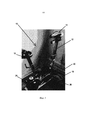
на Фиг. 1 проиллюстрирован стационарный эргометрический тренажер в соответствии с вариантом реализации изобретения;in FIG. 1 illustrates a stationary ergometric trainer in accordance with an embodiment of the invention;
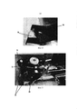
на Фиг. 2 проиллюстрировано измерительное устройство стационарного эргометрического тренажера, проиллюстрированного на Фиг. 1;in FIG. 2 illustrates the measuring device of the stationary ergometric trainer illustrated in FIG. 1;
на Фиг. 3 проиллюстрирован измерительный модуль стационарного эргометрического тренажера, проиллюстрированного на Фиг. 1;in FIG. 3 illustrates the measuring module of the stationary ergometric trainer illustrated in FIG. 1;
на Фиг. 4 проиллюстрирован зубчатый механизм, соединяющий ведущее колесо с маховиком стационарного эргометрического тренажера, проиллюстрированного на Фиг. 1;in FIG. 4 illustrates a gear mechanism connecting the drive wheel to the flywheel of the stationary ergometric trainer illustrated in FIG. 1;
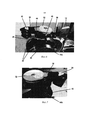
на Фиг. 5 проиллюстрировано тормозное устройство и маховик стационарного эргометрического тренажера;in FIG. 5 illustrates the braking device and the flywheel of a stationary ergometric trainer;
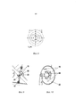
на Фиг. 6 и Фиг. 7 проиллюстрированы управляющий модуль и двигатель, предназначенные для управления перемещением относительно магнитного обода маховика в маховике тормозного устройства;in FIG. 6 and FIG. 7 illustrates a control module and a motor for controlling movement relative to a flywheel magnetic rim in a brake flywheel;
на Фиг. 8 проиллюстрирован пример модели POLAR VIEW™; а такжеin FIG. 8 illustrates an example of a POLAR VIEW ™ model; and
на Фиг. 9 и Фиг. 10 проиллюстрированы схематические изображения измерительного блока, проиллюстрированного на Фиг. 3.in FIG. 9 and FIG. 10 illustrates schematic diagrams of the measuring unit illustrated in FIG. 3.
На Фиг. 1 проиллюстрирован стационарный эргометрический тренажер 10 согласно варианту реализации изобретения.FIG. 1 illustrates a stationary
Стационарный эргометрический тренажер 10 можно использовать, например, в качестве домашнего тренажера, в качестве тренажера в фитнес-студии или для использования в элитных видах спорта. Также, может использоваться в медицинской области при оценивании эффективности.The stationary
Стационарный эргометрический тренажер 10 имеет велосипедную раму 12 с сиденьем 14 и рулями 16. Позиции сиденья 14 и рули 16 регулируются, но предназначены для фиксации во время цикла тренировки. В области стоп под сиденьем 14 тренажер 10 содержит привод для ног, включающий поочередно действующие элементы привода в форме педалей 18, приводимых в движение ногами. Педали 18 установлены с помощью шатунов педалей 20 на противоположных сторонах ведущего колеса 22 посредством педального вала 23 (Фиг. 9), проходящего через ведущее колесо 22.The stationary
Узел 24 маховика соединен с ведущим колесом 22 посредством передачи 26. Для варианта реализации изобретения, проиллюстрированного на Фиг. 1, узел 24 маховика содержит пару маховиков 26, как проиллюстрировано на Фиг. 5, которые установлены для вращения на общем валу 28.The
Передача 26 содержит цепь 30, обвивающую ведущее колеса 22 и промежуточное колесо 32 (Фиг. 2). В результате педалирования 18 вращается вал педали, что и заставляет вращаться ведущее колесо 22. Ведущее колесо 22 посредством цепи 30 приводит во вращательное движение промежуточные колеса 32, цепь 30 приводит в движение вал, проходящий через промежуточное колесо 32 и через дисковое колесо 34, чтобы и вызывает вращение дискового колеса 34.
Дисковое колесо 34 вызывает вращение общего вала 28 для узла маховика 24 посредством ремня 36 (Фиг. 4), который охватывает дисковое колеса 34 и общий вал 28.
Каждый из элементов маховика 26 установлен на общем валу 28 для вращения с ним и выполнен из стали, но включает в себя медный вкладыш, образующий секцию магнитного обода 38 (Фиг. 6). Тормозное устройство 40, содержащее множество постоянных магнитов, установлено для перемещения с помощью серводвигателя 42 в направлении магнитных колес 38 элементов маховика 26 и в противоположном направлении. При перемещении постоянных магнитов в направлении магнитных ободов 38 элементов 26 маховика и в противоположном направлении изменяется сила торможения, которая создается магнитным притяжением между постоянными магнитами и магнитными ободами 38 элементов маховика 26. Соответственно, перемещая постоянные магниты относительно магнитных колес 38, можно регулировать тормозное усилие, прилагаемое к магнитным ободам 38 элементов 26 маховика и тем самым регулировать величину сопротивления вращению элементов 26 маховика, которая создается магнитным притяжением между магнитными ободами 38 элементов 26 маховика и постоянными магнитами.Each of the elements of the
Как проиллюстрировано на Фиг. 5-7, постоянные магниты установлены для формирования двух наборов постоянных магнитов 44а, 44b, закрепленных в кривошипе 46, причем каждый набор постоянных магнитов 44а, 44b установлен на противоположных сторонах кривошипа 46 для перемещения в направлении магнитного обода 38, соответствующего одному из элементов маховика 26 и в противоположном направлении.As illustrated in FIG. 5-7, permanent magnets are mounted to form two sets of
Для перемещения кривошипа 46, кривошип 46 установлен на первом конце резьбового вала 48, который проходит через резьбовое отверстие в опоре 50, установленной на велосипедной раме 12. Резьбовой вал 48 закреплен за второй конец в ведущем колесе 52, которое, в свою очередь, соединено с ведомым валом 54 серводвигателя 42 с помощью приводного ремня 56.To move the
Работа сервомотора 42 приводит во вращение ведомый вал 54, который, в свою очередь, приводит во вращение ведущее колесо 52 с помощью приводного ремня 56. Размещение резьбового вала 48 в резьбовом отверстии, образованном в опоре 50, вызывает продольное перемещение резьбового вала 48 внутрь и извне резьбового отверстия в направлении элементов маховика 26 и в противоположном направлении. Направление перемещения резьбового вала 48 и, следовательно, кривошипа 46, зависит от направления вращения ведомого вала 54 сервомотора 42 и, следовательно, направления вращения резьбового вала 48.The operation of the
Стационарный эргометрический тренажер 10 содержит измерительный блок 58 (Фиг. 2) для измерения, при его использовании, по меньшей мере, одного из приводных усилий, прилагаемых посредством привода, и связанного с ним вращающего момента. В частности, измерительный блок 58 содержит кронштейн 60, прикрепленный к велосипедной раме 12. Накладка 62, предпочтительно выполненная из пластмассы, прикреплена к рычагу 60 для прижатия к наружной кромке цепи 30, соединяющей приводное колесо 22 и промежуточное колесо 32.Stationary
Для варианта осуществления изобретения, который проиллюстрирован на Фиг. 2, накладка 62 слегка прижимает цепь 30 вовнутрь. Для других вариантов реализации изобретения накладка 62 может располагаться на внутренней поверхности цепи для прижатия цепи 30 немного вовне.For the embodiment of the invention that is illustrated in FIG. 2, pad 62 slightly presses
Если цепь 30 натянута, когда движущая сила прикладывается к педалям 18, приводимым в действие ногой пользователя, тогда тангенциальная составляющая силы действует на накладку 62 как восстанавливающая сила, пропорциональная натяжению цепи 30 и, следовательно, приводному усилию. Эластичный изгиб рычага 60 измеряется растягиваемой измерительной полосой 64.If
Понятно, что поскольку восстанавливающая сила пропорциональна натяжению цепи 30 и, следовательно, приводной силе, то измерение восстановительной силы можно использовать для расчета величины движущей силы, приложенной к педалям 18, во время работы стационарного эргометрического тренажера 10.It is understood that since the restoring force is proportional to the tension of the
Аналогично, поскольку известна длина каждого из шатунов 20 педалей, измерения восстанавливающей силы применяются для вычисления момента, приложенного к приводному колесу 22 при помощи педалей 18.Similarly, since the length of each of the pedal crank
Для калибровки измерений силы масса известной величины крепится к одной из педалей 18, а элементы маховика 26 или дисковое колесо 34 блокируются для предотвращения их вращения. Сила, измеренная с помощью измерительного блока 58 при подобных условиях, позволяет калибровать измерительный блок 58 путем сравнения восстанавливающей силы с известной силой, приложенной известной массой, прикрепленной к педали 18 во время функционирований стационарного эргометрического тренажера 10.To calibrate the force measurements, a mass of known magnitude is attached to one of the
Для данного варианта реализации изобретения измерительный блок 58 сконфигурирован для непрерывного измерения приводного усилия, приложенного через привод во время работы тренажера 10. Благодаря непрерывной работе предполагается, что измерительный блок 58 измеряет силу, приложенную через привод до 100 раз в секунду.For this embodiment, the
Стационарный эргометрический тренажер 10 также содержит измерительное устройство 66 (Фиг. 3) для измерения частоты педалирования во время работы тренажера 10.The stationary
Понятно, что в контексте велопоездки частота педалирования относится к скорости педалирования или к количеству оборотов шатунов педалей 20 в минуту (об/мин).It is understood that in the context of cycling, cadence refers to cadence or crank revolutions of 20 cranks per minute (rpm).
Измерительное устройство 66 стационарного эргометрического тренажера 10, проиллюстрированное на Фиг. 1, схематично показано на Фиг. 9 и Фиг. 10, содержит пару частей 68 датчика, установленных на приводном колесе 22, и пару датчиков 70, расположенных на неподвижных местах велосипедной рамы 12.The measuring
Части датчика 68 и датчики 70 расположены относительно друг друга таким образом, что при вращении ведущего колеса 22 каждая из частей датчика 68 проходит мимо одного из датчиков 70, прикрепленных к велосипедной раме 12, так что каждая часть датчика 68 идентифицируется только один раз за цикл вращения ведущего колеса 22 и определяется тем же датчиком 70 при каждом цикле вращения ведущего колеса 22. Это достигается изменением радиального расстояния частей датчика на ведущем колесе 22. В частности, одна из частей датчика 68 расположена на большем радиальном расстоянии от вала педали на ведущем колесе 22, чем другая часть датчика 68. Аналогичным образом, позиционированы датчики 70 на велосипедной раме 12, они расположены в соответствующих друг от друга местах относительно вала педали, и каждый датчик 70 идентифицирует только одну из частей датчика 68 при вращении ведущего колеса 22.The
Относительное положение частей датчика 68 и датчиков 70 также выбирается так, чтобы часть датчика 68 перемещалась в соответствии с относящимся к ней датчиком 70 с интервалом 180° и, таким образом, положение движущегося ведущего колеса 22 в точке, куда каждая из частей датчика 68 перемещается в соответствии с относящемуся к ней датчику 70, соответствует подвижному чередованию нагрузки между педалями 18.The relative position of the parts of the
Соответственно, во время каждого полного оборота ведущего колеса 22 части датчиков 68 и датчики 70 генерируют два сигнала с интервалом 180°. Время между этими сигналами может применяться для вычисления скорости вращения ведущего колеса 22 и, следовательно, скорости педалирования, иначе называемой каденсом.Accordingly, during each complete revolution of the
Аналогичным образом, поскольку сигналы генерируются с интервалом 180° и соответствуют точкам, в которых происходит чередование нагрузки с точки зрения переключения пользователя с одной педали на другую, сигналы, генерируемые частями датчика 68, проходящие через датчики 70, могут интерпретироваться как показатель времени чередования нагрузки.Likewise, since the signals are generated at 180 ° intervals and correspond to the points at which the load alternates in terms of the user switching from one pedal to the other, the signals generated by the portions of the
Для варианта реализации изобретения, который проиллюстрирован на Фиг. 9 и Фиг. 10, части датчика 68 представляют собой магниты, а датчиками 70 служат датчики магнитного поля. Для других вариантов реализации предполагается использование других частей датчиков и датчиков.For the embodiment illustrated in FIG. 9 and FIG. 10, the portions of the
Предусматривается также, что для других вариантов реализации изобретения число частей датчика 68 или количество датчиков 70 может изменяться. В одном из подобных вариантов реализации изобретения один датчик 68 может крепиться к ведущему колесу 22, а датчики 70 могут устанавливаться на велосипедной раме 12 в фиксированных местах, так что часть датчика 68 проходит каждый из датчиков 70 с интервалами, равными 180°. При подобном варианте реализации изобретения часть датчика 68 и датчики 70 снова располагаются относительно друг друга так, что часть датчика 68 перемещается в соответствии с каждым из датчиков 70 во время вращения ведущего колеса 22, в положении движения ведущего колеса 22, соответствующего чередованию нагрузки между педалями 18.It is also contemplated that for other embodiments of the invention, the number of parts of the
Для подобного варианта реализации изобретения части датчика 68 и датчики 70 снова расположены относительно друг друга так, что часть датчика 68 перемещается в соответствии с каждым из датчиков 70 во время вращения ведущего колеса 22 в положении, когда ведущее колесо 22, соответствующее чередованию нагрузки между педалями 18.For such an embodiment, the portions of the
В другом подобном варианте реализации изобретения пара частей датчика 68 может быть прикреплена к ведущему колесу 22, а один датчик 70 может быть установлен на велосипедной раме 12 в фиксированном положении, так что каждая из частей 68 датчика проходит датчик 70 в точке с интервалом, равным 180°. Для подобного варианта реализации изобретения части датчика 68 и датчик 70 снова расположены относительно друг друга таким образом, что датчик 70 обнаруживает соответствующую часть датчика 68 во время вращения ведущего колеса 22 в положении движения ведущего колеса 22, соответствующего чередованию нагрузки между нажатиями на педали 18.In another similar embodiment, a pair of
Для сравнения данных, собранных с помощью измерительного блока 58 и измерительного устройства 66, стационарный эргометрический тренажер 10 включает управляющий модуль 72 (Фиг. 5).To compare the data collected by the measuring
Управляющий модуль 72, предпочтительно, представляет собой программируемое устройство, подключенное к измерительному блоку 58 и измерительному устройству 66 для принятия сигналов, указывающих на приводное усилие, применяемое во время работы тренажера, к цепи 30 и скорость вращения педалей вместе со временем чередования нагрузок между двумя педалями 18.The
Управляющий модуль 72 выполнен с возможностью использования результатов измерений, полученных от измерительного блока 58 и измерительного устройства 66, для вычисления одного или нескольких параметров эффективности работы. Эти параметры эффективности могут включать частоту педалирования, мощность, скорость вращения маховика, приводное усилие, прикладываемое к педалям, и другие выводимые из него значения переменных.The
Подобные параметры эффективности могут передаваться из управляющего модуля 72 в коммуникационный модуль 74 для последующей передачи в пользовательский интерфейс (не показан), подключенный к коммуникационному модулю 74. Кроме того, управляющий модуль 72 сконфигурирован таким образом, чтобы можно было сравнивать, по меньшей мере, один или большее число расчетных параметров эффективности работы с заранее определенным профилем рабочих характеристик.Similar performance parameters can be transmitted from
В зависимости от результатов сравнения, которые будут рассмотрены более подробно ниже, управляющий модуль 74 соединяется с сервомотором 42 и конфигурируется для управления сервомотором 42, что позволяет перемещать два набора постоянных магнитов 44а, 44b по отношению к магнитным ободам 38 элементов маховика 26. При регулировке относительных положений двух наборов постоянных магнитов 44а, 44b относительно магнитных колес 38 элементов 26 маховика управляющий модуль 72 регулирует тормозное усилие, два набора постоянных магнитов 44а, 44b. Это, в свою очередь, оказывает влияние на сопротивление вращению элементов 26 маховика и, таким образом, влияет на измерения, полученные посредством измерительного блока 58 и измерительного устройства 66. Благодаря надлежащему управлению сервомотором 42, управляющий модуль 72 настраивает полученные из измерительного блока 58 и измерительного устройства 66 измерения для регулировки всех параметров или каждого параметра эффективности работы, вычисленного управляющим модулем, в соответствии с заданным профилем рабочих характеристик.Depending on the comparison results, which will be discussed in more detail below, the
Как показано выше, управляющий модуль 72 соединен с коммуникационным модулем 74 для передачи сигналов, представляющих параметры эффективности работы, вычисленные управляющим модулем 72, на внешнее устройство для отображения их с помощью пользовательского интерфейса.As shown above, the
Помимо передачи сигналов внешнему устройству в виде сигналов обратной связи, сообщающих о производительности пользователя, коммуникационный модуль 74 выполнен с возможностью принимать управляющие сигналы и передавать эти сигналы управляющему модулю 72.In addition to transmitting signals to an external device in the form of feedback signals indicating user productivity,
Для варианта реализации изобретения, который проиллюстрирован на Фиг. 1, коммуникационный модуль 74 содержит радиомодуль, сконфигурированный для приема управляющих сигналов и передачи сигналов обратной связи по протоколу беспроводной связи, известному как BLUETOOTH®. Поддерживается беспроводное соединение коммуникационного модуля 74 с внешним устройством, таким как смартфон, планшет, смарт-часы или другое вычислительное устройство.For the embodiment illustrated in FIG. 1,
Для других вариантов реализации изобретения предполагается, что для создания беспроводного соединения между коммуникационным модулем 74 и внешним устройством может использоваться другой протокол беспроводной связи, такой как ANT+®. Также предполагается, что проводное соединение может использоваться для соединения коммуникационного модуля 74 с внешним устройством. Коммуникационный модуль 74 может, например, подключаться к внешнему устройству с помощью кабеля передачи данных, такого как USB-кабель.For other embodiments of the invention, it is contemplated that a different wireless protocol, such as ANT +®, can be used to create a wireless connection between the
Использование коммуникационного модуля 74 для облегчения соединения с внешним устройством, таким как смартфон, планшет, смарт-часы или другое вычислительное устройство, позволяет формировать пользовательский интерфейс. Предусмотрено, что коммуникационный модуль 74 связи может подключаться к смартфону, планшету, смарт-часам или другому вычислительному устройству, на котором выполняется приложение, настроенное для связи с коммуникационным модулем 74, и, таким образом, разрешает пользователю вводить данные для формирования предопределенного профиля рабочих характеристик.The use of
Коммуникационный модуль 74 также может подключаться к подобному устройству для обеспечения возможности по визуализации сигналов обратной связи на экране устройства. Интерфейс может, например, отображать измерения частоты педалирования и/или приложенной силы. Также может или альтернативно отображать один или несколько параметров производительности работы, вычисленных управляющим модулем на основе измерений, полученных из измерительного блока 58 и измерительного устройства 66.The
Интерфейс может также включать дисплей POLAR VIEW™ в зависимости от периодов чередования нагрузки, который определяется измерительным устройством 66, и измеренных величин силы, а также других значений переменных, вычисленных управляющим модулем 72 в ответ на результаты измерений, поступивших от измерительного блока 58. Формирование дисплея POLAR VIEW™, отображающего график зависимости усилия от времени, иллюстрирует эффективность работы и технику использования педалей пользователем при конкретной ссылке на особенности работы правой и левой конечностей пользователя. Поэтому у пользователя тренажера формируется иллюзия скоростной езды на велосипеде, что разрешает пользователю визуально определять области, где эффективность работы и/или техника педалирования требуют улучшения.The interface may also include a POLAR VIEW ™ display depending on the load rotation periods as determined by the
Пример дисплея POLAR VIEW™ проиллюстрирован на Фиг. 8.An example of a POLAR VIEW ™ display is illustrated in FIG. 8.
Теперь переходим к описанию работы стационарного эргометрического тренажера 10.Now we turn to the description of the work of the stationary
Во время работы тренажера 10 пользователь управляет вращением элементов маховика 26, работая педалями 18. Результирующее приводное усилие, прилагаемое к цепи, обвивающей ведущее колесо 22, измеряется с помощью измерительного блока 58 в непрерывном режиме, как указано выше, и полученные измерения передаются управляющему модулю 72.During the operation of the
Аналогично, частота или скорость педалирования измеряются измерительным устройством 66, и полученные результаты измерений вместе с сигналами, указывающими время чередования нагрузок между педалями 18, передаются управляющему модулю 72.Likewise, the cadence or cadence is measured by the
Управляющий модуль 72 использует измерения и сигналы, полученные от измерительного устройства 58, а также от измерительного блока 66, вычисляет выходную мощность пользователя тренажера.The
Управляющий блок 72, предпочтительно, вычисляет выходную мощность пользователя один раз за один оборот шатунов педалей 20 на основании формулы, при которой мощность = сила × скорость, а скорость может быть рассчитана со ссылкой на измеренную частоту педалирования и пройденное расстояние за оборот педали 20. Как указано выше, расстояние, пройденное за оборот шатунов педали 20, может предварительно устанавливаться в управляющем модуле 72 в соответствии с рядом предварительно установленных передач. Управляющий модуль 72 может выполняться с возможностью увеличения силы торможения, прилагаемой к узлу маховика 24 путем выбора пользователем более высокой передачи, и, наоборот, при имитации дополнительного сопротивления, которое будет испытывать велосипедист при переключении передач на настоящем велосипеде. Аналогично, управляющий модуль 72 может конфигурироваться для увеличения расстояния, пройденного за оборот шатунов педалей 20 при нарастании передач от самой низкой передачи до самой высокой, и наоборот.The
В особенно предпочтительном варианте реализации изобретения расстояние, пройденное за оборот шатунов педалей, увеличивается постепенно от минимума 2,790 м для нижней передачи (передача 1), до максимального - 10,258 м для верхней передачи (передача 22), как указано в таблице 1, приведенной ниже.In a particularly preferred embodiment of the invention, the distance traveled per crank rotation of the pedals increases gradually from a minimum of 2.790 m for the lower gear (gear 1) to a maximum of 10.258 m for the upper gear (gear 22), as indicated in Table 1 below.


Для подобных вариантов реализации изобретения понятно, что пользователь, управляющий тренажером при выбранной передаче 1 с частотой вращения шатунов педалей 60 оборотов в минуту, будет имитировать езду со скоростью 2,790 м/с.For such embodiments of the invention, it is clear that a user operating the simulator in the selected gear 1 with a crank speed of 60 rpm will simulate a ride at a speed of 2.790 m / s.
Чтобы разрешить пользователю изменять передачи, на руль 16 можно поместить кнопки (не проиллюстрированы), что разрешит пользователю с легкостью переключать передачи, как если бы речь шла о езде на настоящем велосипеде. Такие кнопки могут подключаться к управляющему модулю 72 для обеспечения необходимого сигнала, предпочтительно предусмотреть одну кнопку для переключения вверх по передачам, а вторую - для переключения вниз по передачам.Buttons (not illustrated) can be placed on the
Для других вариантов реализации изобретения кнопки выполнены с возможностью отправки управляющих сигналов коммуникационному модулю 74 для последующей передачи управляющему модулю 72.For other embodiments of the invention, the buttons are configured to send control signals to the
Управляющий модуль 72 может вычислять и другие параметры или значения переменных, отражающие эффективность работы, которые выводятся из приводного усилия для последующей передачи их через коммуникационный модуль 74 внешнему устройству, подключенному к коммуникационному модулю 74, для поддержки пользовательского интерфейса.The
В простейшей форме пользователь может создать предопределенный профиль рабочих характеристик в управляющем модуле 72, что позволит гарантировать достижение постоянной выходной мощности пользователем во время работы тренажера 10. Этого можно достичь, измеряя частоту педалирования и прилагаемую силу для расчета фактической выходной мощности пользователя, сравнивая вычисленную мощность с величиной выходной мощности, требуемой заданным профилем рабочих характеристик, управляя двигателем для увеличения или уменьшения тормозного усилия, что потребует от пользователя применения большей или меньшей силы для достижения требуемой выходной мощности при той же частоте педалирования.In its simplest form, the user can create a predefined performance profile in the
Пользователь может также выбирать из ряда предопределенных профилей рабочих характеристик еще до начала тренировки. Пользователь может, например, выбрать предопределенный профиль рабочих характеристик, который определяется нелинейной зависимостью между мощностью и частотой вращения педалей для конкретной передачи. Затем при работе тренажера 10, управляющий модуль 72 использует результаты измерения частоты педалирования и приложенной силы для расчета фактической выходной мощности пользователя и сравнит вычисленное значение мощности с измеренной частотой педалирования, учитывая нелинейную зависимость между мощностью и частотой педалирования, которые определяют заданный профиль рабочих характеристик.The user can also choose from a number of predefined performance profiles before starting a workout. The user can, for example, select a predefined performance profile that is determined by a non-linear relationship between power and cadence for a particular gear. Then, when the
При выполнении этого сравнения управляющий модуль 72 может определить, является ли фактическая выходная мощность пользователя более высокой или меньшей, чем требуется в соответствии с заранее заданным профилем производительности для измеренной частоты вращения педалей, и управляет сервомотором 42, чтобы отрегулировать относительные положения наборов постоянных магнитов 44а, 44b относительно элементов 26 маховика, чтобы отрегулировать тормозное усилие, прилагаемое наборами постоянных магнитов 44а, 44b к элементам маховика 26. Это, в свою очередь, увеличивает или уменьшает усилие, требуемое от пользователя тренажера при вращении педалей с одинаковой частотой, и может использоваться для настройки результатов измерений, полученных от измерительного блока 58 и измерительного устройства 66, так что рассчитанная выходная мощность пользователя соответствует мощности, требуемой заданным профилем производительности для измеренной частоты вращения педалей.When making this comparison, the
В варианте реализации изобретения, проиллюстрированном на фигурах, управляющий модуль 72 также конфигурируется для вычисления предварительно определенного профиля рабочих характеристик при получении данных об эффективности работы в виде управляющих сигналов от коммуникационного модуля 74.In the embodiment illustrated in the figures, the
Пользователь может вводить ряд параметров, характеризующих велопоездку, во внешнее устройство, подключенное к коммуникационному модулю 74, которые, в свою очередь, передаются управляющему модулю 72 через коммуникационный модуль 74 и разрешают управляющему модулю 72 вычислять заданные пользователем предварительно определенные данные профиля рабочих характеристик на основе выбранных параметров велопоездки.The user can enter a number of cycling parameters into an external device connected to the
Данные, характеризующие эффективность работы, могут включать информацию, относящуюся к одному или нескольким параметрам статического режима велопоездки, которые выбраны из группы, состоящей из угла наклона трассы движения, сопротивления качению между шинами и поверхностью трассы, массы велосипедиста, массы велосипеда и мощности велосипедиста.Performance data may include information related to one or more static cycling parameters selected from the group consisting of track angle, tire-to-track rolling resistance, rider weight, bike weight, and rider power.
Данные, характеризующие эффективность работы, могут также включать информацию, относящуюся к одному или нескольким параметрам динамического режима велопоездки, которые выбраны из группы, состоящей из сопротивления воздуха, создаваемого изменениями скорости ветра, сопротивления воздуха, создаваемого изменениями высоты и сопротивления воздуха, создаваемым с помощью вентилятора.Performance data may also include information related to one or more dynamic cycling parameters selected from the group consisting of air resistance from changes in wind speed, air resistance from changes in altitude, and air resistance from a fan. ...
При получении подобной информации от внешнего устройства в виде управляющих сигналов, принятых через коммуникационный модуль 74, управляющий модуль 72 выполнен с возможностью вычисления эффектов любых выбранных параметров велопоездки, оказывающих влияние на силу лобового сопротивления, которое испытывает велосипедист в этих условиях. В свою очередь, подобный подход разрешает управляющему модулю 72 вычислять заданный профиль рабочих характеристик с учетом дополнительной силы лобового сопротивления.Upon receiving such information from an external device in the form of control signals received through the
В особенно предпочтительном варианте реализации изобретения расстояние, пройденное за оборот педалей 20, предварительно задано в управляющем модуле в соответствии с рядом предварительно установленных передач, указанных в приведенной выше таблице 1, управляющий модуль 72 вычисляет необходимую дополнительную мощность для преодоления силы лобового сопротивления, создаваемой массой тела пользователя 70 кг на плоской дороге без уклона и нулевого сопротивления ветра в соответствии с предварительно установленным комплектом снаряжения и примерными показателями частоты педалирования, как указано ниже в таблице 2.In a particularly preferred embodiment of the invention, the distance traveled per revolution of the


Понятно, что сила лобового сопротивления, которая создается, когда пользователь едет на велосипеде в подобных условиях, увеличивается с ростом частоты педалирования пользователем тренажера для каждой передачи и, таким образом, при увеличении скорости движения велосипеда.It is understood that the drag force that is generated when a user rides a bicycle under such conditions increases with the user's cadence for each gear and thus the speed of the bicycle increases.
Примеры мощности, необходимой для преодоления силы лобового сопротивления в случае выбора передач 1, 10 и 22 для увеличения частоты педалирования с приращениями, рассчитанной управляющим модулем, приведены ниже в таблицах 3, 4 и 5.Examples of the power required to overcome the drag force when gears 1, 10 and 22 are selected to increase the cadence incrementally calculated by the Control Unit are shown in Tables 3, 4 and 5 below.


Управляющий модуль 72 может, например, генерировать заранее определенный профиль рабочих характеристик на основе выходной мощности по сравнению с частотой педалирования, которая рассчитывается с учетом силы лобового сопротивления, которую будет испытывать велосипедист в результате выбранных параметров велопоездки. Это позволяет управляющему модулю 72 управлять сервомотором 42 и тем самым управлять перемещением наборов постоянных магнитов 44а, 44b относительно магнитных колес 38 элементов маховика 26 для формирования необходимой силы лобового сопротивления и, таким образом, выполнить имитацию различных условий велопоездки.The
При соответствующем выборе параметров велопоездки пользователь может формировать управляющие сигналы, которые инструктируют управляющий модуль 72 по поводу имитации множества комбинаций, связанных с условиями велопоездки. Например, управляющий модуль 72 может имитировать условия легкого веса велосипедиста, который ездит на легком велосипеде по поверхности велодрома; того же велосипедиста при перемещении по грунтовой дороге; тот же велосипедист перемещается по наклонной поверхности при наклоне ее на 5°; тот же велосипедист перемещается по наклонной поверхности -5° при попутном ветре, скорость которого равна 10 миль в час.With an appropriate selection of cycling parameters, the user can generate control signals that instruct the
Управляющий модуль 72 может, например, имитировать стационарный эргометрический тренажер, имеющий вентилятор с вентиляционными отверстиями на внешнем корпусе вентилятора, который может регулироваться таким образом, чтобы принимать различные положения, воздействовать на воздушный поток, проходящий через вентилятор, работать педалями для поддержки вращения вентилятора.The
Если обратиться к упомянутым выше динамическим параметрам велопрогулки, сила лобового сопротивления, испытываемая велосипедистом в подобных условиях, будет варьироваться в зависимости от скорости потока. Соответственно, управляющий модуль 72 может выполняться с возможностью использования измерений, полученных от измерительного устройства 58, для вычисления скорости вращения элементов маховика 26 или эквивалентной скорости реального велосипеда, работающего при той же частоте педалирования и той же движущей силе.Referring to the aforementioned dynamic parameters of a bike ride, the drag force experienced by a cyclist under these conditions will vary depending on the flow rate. Accordingly, the
Скорость реального велосипеда может быть рассчитана, как описано выше, со ссылкой на измеренную частоту педалирования и пройденное расстояние за один оборот шатунов педалей 20.The speed of a real bike can be calculated as described above with reference to the measured cadence and distance traveled per crank
Скорость вращения элементов маховика 26 также указывает на фактическую скорость велосипеда, который может также или альтернативно использоваться управляющим модулем 72 для настройки заданного профиля эффективности, чтобы отразить влияние скорости пользователя на один или более динамических параметров велопоездки, используемых при вычислении заданного профиля рабочих характеристики.The rotational speed of the
Для других вариантов реализации изобретения внешнее устройство может включать данные, относящиеся к велосипедному маршруту, которые могут применяться для формирования управляющих сигналов при имитации конкретного маршрута. Данные могут, например, относиться к определенному этапу велогонки Тур де Франс или маршруту олимпийской трассы.For other embodiments of the invention, the external device may include data related to the cycling route that can be used to generate control signals when simulating a particular route. The data can, for example, relate to a specific stage in the Tour de France or the route of an Olympic track.
Для подобных вариантов реализации изобретения управляющий модуль 72 может выполняться с возможностью генерирования заранее определенного профиля рабочих характеристик на основе управляющих сигналов, относящихся к характеристикам выбранного маршрута. Такие характеристики могут включать угол наклона, сопротивление качению между шинами велосипеда и поверхностью трассы и высотой велосипедиста. Сюда также входят скорость ветра, направление ветра и другие метеорологические характеристики в том случае, если пользователь решит имитировать точные условия ранее записанной поездки по выбранному маршруту.For such embodiments,
Во время моделирования управляющий модуль 72 вычисляет выходную мощность пользователя в соответствии с вышеописанными методами и сравнивает с заданным профилем рабочих характеристик для определения выходной мощности, которая требуется при измеренной частоте педалирования пользователя тренажера. Это позволяет управляющему модулю 72 регулировать работу сервомотора 42 и тем самым управлять перемещением наборов постоянных магнитов 44а, 44b относительно магнитных колес 38 элементов 26 маховика для настройки измерений, полученных от измерительного блока 58 и измерительного устройства 66, что позволит обеспечить требуемую выходную мощность и, таким образом, имитировать сопротивление педалированию, которое будет испытывать пользователь тренажера при данной частоте педалирования, на выбранной передаче и в положении по реализуемому пользователем маршруту.During the simulation, the
Понятно, что данные, относящиеся к выбранному маршруту, могут быть представлены в виде одной передачи от внешнего устройства через коммуникационный модуль 74. Однако также понятно, что данные могут непрерывно передаваться от внешнего устройства управляющему модулю 72 через коммуникационный модуль 74 во время моделирования выбранного маршрута, что позволит обеспечить предоставление большего количества данных и, таким образом, облегчит постоянную корректировку заданного профиля рабочих характеристик и более подробное и точное моделирование.It is understood that data related to the selected route may be represented as a single transmission from an external device via
В любом случае управляющий модуль 72 может передавать сигналы обратной связи через коммуникационный модуль 74 обратно внешнему устройству, что позволяет внешнему устройству отслеживать процесс перемещения пользователя по выбранному маршруту. Имеется возможность по передаче сигнала внешнему устройству, что позволит внешнему устройству сгенерировать видеоизображение, обеспечивающее пользователю возможность визуализации перемещения по выбранному маршруту.In any case, the
Claims (42)
Applications Claiming Priority (3)
| Application Number | Priority Date | Filing Date | Title |
|---|---|---|---|
| GB1600466.5A GB2546113A (en) | 2016-01-11 | 2016-01-11 | Stationary ergometric exercise device |
| GB1600466.5 | 2016-01-11 | ||
| PCT/GB2017/050062 WO2017122007A1 (en) | 2016-01-11 | 2017-01-11 | Stationary ergometric exercise device |
Publications (1)
| Publication Number | Publication Date |
|---|---|
| RU2729088C1 true RU2729088C1 (en) | 2020-08-04 |
Family
ID=55445829
Family Applications (1)
| Application Number | Title | Priority Date | Filing Date |
|---|---|---|---|
| RU2018129171A RU2729088C1 (en) | 2016-01-11 | 2017-01-11 | Stationary ergometric exerciser |
Country Status (17)
| Country | Link |
|---|---|
| US (2) | US11235198B2 (en) |
| EP (1) | EP3402579B1 (en) |
| JP (1) | JP6989520B2 (en) |
| CN (1) | CN108883334B (en) |
| AU (1) | AU2017208029B2 (en) |
| BR (1) | BR112018014162A2 (en) |
| CA (1) | CA3010766C (en) |
| CY (1) | CY1125685T1 (en) |
| DK (1) | DK3402579T3 (en) |
| ES (1) | ES2885831T3 (en) |
| GB (1) | GB2546113A (en) |
| PL (1) | PL3402579T3 (en) |
| PT (1) | PT3402579T (en) |
| RU (1) | RU2729088C1 (en) |
| TW (1) | TWI718229B (en) |
| WO (1) | WO2017122007A1 (en) |
| ZA (1) | ZA201805335B (en) |
Families Citing this family (12)
| Publication number | Priority date | Publication date | Assignee | Title |
|---|---|---|---|---|
| CZ307852B6 (en) * | 2017-05-24 | 2019-06-26 | Technická univerzita v Liberci | Rehabilitation ergometer and its control |
| FR3074712B1 (en) | 2017-12-13 | 2020-07-31 | Innovation Fabrication Commercialisation Infaco | ELECTRO PORTABLE MOTORIZED PRUNER EQUIPPED WITH A MORE ERGONOMIC AND SAFE SAFETY DEVICE. |
| GB201810397D0 (en) * | 2018-06-25 | 2018-08-08 | Wattbike Ip Ltd | Method and apparartus for monitoring user effectivness during operation of an exercise machine |
| EP3679995B1 (en) * | 2019-01-14 | 2021-07-21 | Emotion Fitness GmbH & Co. KG | Stationary exercise device |
| CN109908551B (en) * | 2019-02-02 | 2022-02-15 | 随机漫步(上海)体育科技有限公司 | Bicycle exercise method and device |
| EP4004190A4 (en) * | 2019-07-26 | 2023-11-22 | Pandorum Technologies Private Limited | Bioengineered formulation, process for preparing and implementations thereof |
| JP7370480B2 (en) * | 2020-04-23 | 2023-10-27 | ダイナミック アクセッション リミテッド ライアビリティ カンパニー | dynamic exercise resistance module |
| TWI774062B (en) * | 2020-09-15 | 2022-08-11 | 緯創資通股份有限公司 | Training device |
| CN112755441B (en) * | 2020-12-25 | 2024-06-04 | 南通铁人运动用品有限公司 | Wind magnetic resistance dynamometer vehicle |
| CN117839158A (en) * | 2021-07-12 | 2024-04-09 | 宁波篆和科技有限公司 | Resistance-adjustable rotating wheel, adjusting method thereof and sports equipment |
| CN114272559B (en) * | 2021-12-28 | 2023-03-24 | 青岛迈金智能科技股份有限公司 | Intelligent riding device and power calculation method thereof |
| TWI790900B (en) * | 2022-01-17 | 2023-01-21 | 志合訊息股份有限公司 | Speed generation method for simulating riding |
Citations (4)
| Publication number | Priority date | Publication date | Assignee | Title |
|---|---|---|---|---|
| RU2081645C1 (en) * | 1993-12-27 | 1997-06-20 | Владимир Дмитриевич Болотов | Bicycle-type training apparatus |
| WO2007015096A2 (en) * | 2005-08-03 | 2007-02-08 | Andrew Robert Loach | Exercise machine |
| WO2012042092A1 (en) * | 2010-10-01 | 2012-04-05 | Bkool, S.L. | Sports training device |
| US8641581B2 (en) * | 2007-08-30 | 2014-02-04 | Wattbike Ip Limited | Ergometric training device |
Family Cites Families (30)
| Publication number | Priority date | Publication date | Assignee | Title |
|---|---|---|---|---|
| US3641581A (en) | 1968-06-18 | 1972-02-08 | Projektovy Ustav Dopravnich A | Method and arrangement for registering and recording of deformations of materials |
| US4938475A (en) * | 1987-05-26 | 1990-07-03 | Sargeant Bruce A | Bicycle racing training apparatus |
| JPH044765Y2 (en) | 1987-12-29 | 1992-02-12 | ||
| JPH079363U (en) * | 1993-07-29 | 1995-02-10 | レアオ,ワン | Exercise Bike Magnetic Resistance Adjuster |
| JP3009143U (en) * | 1994-07-26 | 1995-03-28 | グリーンマスター インダストリアル コーポレイション | Magnetic control device that automatically controls the magnetic tension according to the setting of the watt value that represents momentum |
| WO2003034584A1 (en) | 2001-09-28 | 2003-04-24 | Graber Products, Inc. | Self-powered variable resistance bicycle trainer |
| US6726586B2 (en) | 2001-11-09 | 2004-04-27 | Shimano Inc. | Motorized bicycle actuator assembly |
| JP2003231491A (en) | 2002-02-08 | 2003-08-19 | Sunstar Eng Inc | Power-assisted bicycle providing aerobic exercise |
| CN1247284C (en) * | 2003-05-27 | 2006-03-29 | 李明 | Method and apparatus for realizing virtual riding bicycle |
| CN2675543Y (en) | 2004-01-29 | 2005-02-02 | 黄岩 | Sensing device for intelligent electric bicycle |
| US7648446B2 (en) * | 2004-06-09 | 2010-01-19 | Unisen, Inc. | System and method for electronically controlling resistance of an exercise machine |
| EP1868695A4 (en) * | 2005-03-23 | 2008-07-30 | Saris Cycling Group Inc | Closed loop control of resistance in a resistance-type exercise system |
| NO20055233D0 (en) * | 2005-11-08 | 2005-11-08 | Kalifen As | Indoor exercise bike with tilt function |
| TWM295528U (en) * | 2006-02-10 | 2006-08-11 | Yun-Ting Chiou | Resistance device of magnetically controlled flywheel for indoor exercising equipment |
| CN100588588C (en) * | 2006-11-15 | 2010-02-10 | 赵正康 | Electric bicycle |
| US20100035726A1 (en) | 2008-08-07 | 2010-02-11 | John Fisher | Cardio-fitness station with virtual-reality capability |
| US8585561B2 (en) | 2009-03-13 | 2013-11-19 | Nautilus, Inc. | Exercise bike |
| TW201103602A (en) * | 2009-07-27 | 2011-02-01 | Footwear & Recreation Technology Res Inst | Exercise bike with speed control system |
| US9468794B2 (en) * | 2011-09-01 | 2016-10-18 | Icon Health & Fitness, Inc. | System and method for simulating environmental conditions on an exercise bicycle |
| CN102363068A (en) * | 2011-11-17 | 2012-02-29 | 河南理工大学 | Fitness bicycle |
| DE102012019338A1 (en) * | 2012-10-02 | 2014-04-03 | Andreas Fischer | Stationary exercise bike |
| EP2931389B1 (en) * | 2012-12-12 | 2018-10-17 | Freiberg, Michael | Cycling training device |
| US9868028B2 (en) * | 2013-09-04 | 2018-01-16 | Considerc Inc. | Virtual reality indoor bicycle exercise system using mobile device |
| TWD163790S (en) | 2013-10-31 | 2014-10-21 | 好吉康健美科技有限公司 | Exercise bike |
| CN103920287B (en) * | 2014-05-06 | 2017-01-11 | 许昌学院 | Virtual scene network exercise bicycle |
| TWD167127S (en) | 2014-07-22 | 2015-04-11 | 朗美(廈門)健身器材有限公司 | exercise bike |
| CN105056475A (en) * | 2015-07-17 | 2015-11-18 | 南京空山新雨环保科技有限公司 | Exercise bike having motion sensing game function |
| EP3341092B1 (en) * | 2015-08-25 | 2021-07-14 | Virtureal Development GmbH | Stationary exercise apparatus for indoor cycling |
| NL2016180B1 (en) * | 2016-01-28 | 2017-08-01 | Tacx Roerend En Onroerend Goed B V | Bicycle trainer and method of its operation. |
| IT201600083062A1 (en) * | 2016-08-05 | 2018-02-05 | Technogym Spa | Exercise equipment for cycling simulation and its method of operation. |
-
2016
- 2016-01-11 GB GB1600466.5A patent/GB2546113A/en not_active Withdrawn
-
2017
- 2017-01-11 CN CN201780012248.1A patent/CN108883334B/en active Active
- 2017-01-11 CA CA3010766A patent/CA3010766C/en active Active
- 2017-01-11 ES ES17704522T patent/ES2885831T3/en active Active
- 2017-01-11 PL PL17704522T patent/PL3402579T3/en unknown
- 2017-01-11 AU AU2017208029A patent/AU2017208029B2/en active Active
- 2017-01-11 RU RU2018129171A patent/RU2729088C1/en active
- 2017-01-11 BR BR112018014162A patent/BR112018014162A2/en not_active Application Discontinuation
- 2017-01-11 EP EP17704522.6A patent/EP3402579B1/en active Active
- 2017-01-11 DK DK17704522.6T patent/DK3402579T3/en active
- 2017-01-11 PT PT177045226T patent/PT3402579T/en unknown
- 2017-01-11 TW TW106100828A patent/TWI718229B/en active
- 2017-01-11 US US16/069,229 patent/US11235198B2/en active Active
- 2017-01-11 WO PCT/GB2017/050062 patent/WO2017122007A1/en active Application Filing
- 2017-01-11 JP JP2018555312A patent/JP6989520B2/en active Active
-
2018
- 2018-08-10 ZA ZA2018/05335A patent/ZA201805335B/en unknown
-
2021
- 2021-09-02 CY CY20211100781T patent/CY1125685T1/en unknown
- 2021-11-30 US US17/457,018 patent/US11565149B2/en active Active
Patent Citations (4)
| Publication number | Priority date | Publication date | Assignee | Title |
|---|---|---|---|---|
| RU2081645C1 (en) * | 1993-12-27 | 1997-06-20 | Владимир Дмитриевич Болотов | Bicycle-type training apparatus |
| WO2007015096A2 (en) * | 2005-08-03 | 2007-02-08 | Andrew Robert Loach | Exercise machine |
| US8641581B2 (en) * | 2007-08-30 | 2014-02-04 | Wattbike Ip Limited | Ergometric training device |
| WO2012042092A1 (en) * | 2010-10-01 | 2012-04-05 | Bkool, S.L. | Sports training device |
Also Published As
| Publication number | Publication date |
|---|---|
| ZA201805335B (en) | 2021-03-31 |
| CY1125685T1 (en) | 2024-02-16 |
| AU2017208029B2 (en) | 2021-09-09 |
| EP3402579B1 (en) | 2021-06-02 |
| BR112018014162A2 (en) | 2018-12-11 |
| TWI718229B (en) | 2021-02-11 |
| PT3402579T (en) | 2021-09-07 |
| CN108883334A (en) | 2018-11-23 |
| PL3402579T3 (en) | 2022-02-14 |
| US11235198B2 (en) | 2022-02-01 |
| EP3402579A1 (en) | 2018-11-21 |
| US11565149B2 (en) | 2023-01-31 |
| JP2019501002A (en) | 2019-01-17 |
| AU2017208029A1 (en) | 2018-08-30 |
| US20190046834A1 (en) | 2019-02-14 |
| JP6989520B2 (en) | 2022-01-05 |
| WO2017122007A1 (en) | 2017-07-20 |
| US20220080255A1 (en) | 2022-03-17 |
| GB2546113A (en) | 2017-07-12 |
| NZ745142A (en) | 2021-09-24 |
| CN108883334B (en) | 2022-01-11 |
| CA3010766C (en) | 2023-03-21 |
| DK3402579T3 (en) | 2021-09-13 |
| GB201600466D0 (en) | 2016-02-24 |
| TW201738542A (en) | 2017-11-01 |
| ES2885831T3 (en) | 2021-12-15 |
| CA3010766A1 (en) | 2017-07-20 |
Similar Documents
| Publication | Publication Date | Title |
|---|---|---|
| RU2729088C1 (en) | Stationary ergometric exerciser | |
| US7648446B2 (en) | System and method for electronically controlling resistance of an exercise machine | |
| US8272997B2 (en) | Stride adjustment mechanism | |
| AU2008291668B2 (en) | Ergometric training device | |
| JP2019501002A5 (en) | ||
| US20060094569A1 (en) | Exercise machine and method for use in training selected muscle groups | |
| US20050209056A1 (en) | Elliptical step distance measurement | |
| US20140080675A1 (en) | Stride adjustment mechanism | |
| AU2019293144B2 (en) | Method and apparatus for monitoring user effectiveness during operation of an exercise machine | |
| NZ745142B2 (en) | Stationary ergometric exercise device | |
| RU2822082C2 (en) | Method and device for monitoring the efficiency of user actions during operation of the simulator | |
| US20230302326A1 (en) | Method of controlling a force and/or resistance generator of an exercise apparatus | |
| CA2758142C (en) | Stride adjustment mechanism |