JP6989520B2 - Stationary ergometric exercise device - Google Patents
Stationary ergometric exercise device Download PDFInfo
- Publication number
- JP6989520B2 JP6989520B2 JP2018555312A JP2018555312A JP6989520B2 JP 6989520 B2 JP6989520 B2 JP 6989520B2 JP 2018555312 A JP2018555312 A JP 2018555312A JP 2018555312 A JP2018555312 A JP 2018555312A JP 6989520 B2 JP6989520 B2 JP 6989520B2
- Authority
- JP
- Japan
- Prior art keywords
- flywheel
- measuring
- user
- stationary
- exercise device
- Prior art date
- Legal status (The legal status is an assumption and is not a legal conclusion. Google has not performed a legal analysis and makes no representation as to the accuracy of the status listed.)
- Active
Links
Images


Classifications
-
- A—HUMAN NECESSITIES
- A63—SPORTS; GAMES; AMUSEMENTS
- A63B—APPARATUS FOR PHYSICAL TRAINING, GYMNASTICS, SWIMMING, CLIMBING, OR FENCING; BALL GAMES; TRAINING EQUIPMENT
- A63B24/00—Electric or electronic controls for exercising apparatus of preceding groups; Controlling or monitoring of exercises, sportive games, training or athletic performances
-
- A—HUMAN NECESSITIES
- A63—SPORTS; GAMES; AMUSEMENTS
- A63B—APPARATUS FOR PHYSICAL TRAINING, GYMNASTICS, SWIMMING, CLIMBING, OR FENCING; BALL GAMES; TRAINING EQUIPMENT
- A63B22/00—Exercising apparatus specially adapted for conditioning the cardio-vascular system, for training agility or co-ordination of movements
- A63B22/06—Exercising apparatus specially adapted for conditioning the cardio-vascular system, for training agility or co-ordination of movements with support elements performing a rotating cycling movement, i.e. a closed path movement
- A63B22/0605—Exercising apparatus specially adapted for conditioning the cardio-vascular system, for training agility or co-ordination of movements with support elements performing a rotating cycling movement, i.e. a closed path movement performing a circular movement, e.g. ergometers
-
- A—HUMAN NECESSITIES
- A61—MEDICAL OR VETERINARY SCIENCE; HYGIENE
- A61B—DIAGNOSIS; SURGERY; IDENTIFICATION
- A61B5/00—Measuring for diagnostic purposes; Identification of persons
- A61B5/22—Ergometry; Measuring muscular strength or the force of a muscular blow
- A61B5/221—Ergometry, e.g. by using bicycle type apparatus
-
- A—HUMAN NECESSITIES
- A63—SPORTS; GAMES; AMUSEMENTS
- A63B—APPARATUS FOR PHYSICAL TRAINING, GYMNASTICS, SWIMMING, CLIMBING, OR FENCING; BALL GAMES; TRAINING EQUIPMENT
- A63B21/00—Exercising apparatus for developing or strengthening the muscles or joints of the body by working against a counterforce, with or without measuring devices
- A63B21/005—Exercising apparatus for developing or strengthening the muscles or joints of the body by working against a counterforce, with or without measuring devices using electromagnetic or electric force-resisters
- A63B21/0051—Exercising apparatus for developing or strengthening the muscles or joints of the body by working against a counterforce, with or without measuring devices using electromagnetic or electric force-resisters using eddy currents induced in moved elements, e.g. by permanent magnets
-
- A—HUMAN NECESSITIES
- A63—SPORTS; GAMES; AMUSEMENTS
- A63B—APPARATUS FOR PHYSICAL TRAINING, GYMNASTICS, SWIMMING, CLIMBING, OR FENCING; BALL GAMES; TRAINING EQUIPMENT
- A63B21/00—Exercising apparatus for developing or strengthening the muscles or joints of the body by working against a counterforce, with or without measuring devices
- A63B21/22—Resisting devices with rotary bodies
- A63B21/225—Resisting devices with rotary bodies with flywheels
-
- A—HUMAN NECESSITIES
- A63—SPORTS; GAMES; AMUSEMENTS
- A63B—APPARATUS FOR PHYSICAL TRAINING, GYMNASTICS, SWIMMING, CLIMBING, OR FENCING; BALL GAMES; TRAINING EQUIPMENT
- A63B22/00—Exercising apparatus specially adapted for conditioning the cardio-vascular system, for training agility or co-ordination of movements
- A63B22/06—Exercising apparatus specially adapted for conditioning the cardio-vascular system, for training agility or co-ordination of movements with support elements performing a rotating cycling movement, i.e. a closed path movement
-
- A—HUMAN NECESSITIES
- A63—SPORTS; GAMES; AMUSEMENTS
- A63B—APPARATUS FOR PHYSICAL TRAINING, GYMNASTICS, SWIMMING, CLIMBING, OR FENCING; BALL GAMES; TRAINING EQUIPMENT
- A63B23/00—Exercising apparatus specially adapted for particular parts of the body
- A63B23/035—Exercising apparatus specially adapted for particular parts of the body for limbs, i.e. upper or lower limbs, e.g. simultaneously
- A63B23/04—Exercising apparatus specially adapted for particular parts of the body for limbs, i.e. upper or lower limbs, e.g. simultaneously for lower limbs
- A63B23/0476—Exercising apparatus specially adapted for particular parts of the body for limbs, i.e. upper or lower limbs, e.g. simultaneously for lower limbs by rotating cycling movement
-
- A—HUMAN NECESSITIES
- A63—SPORTS; GAMES; AMUSEMENTS
- A63B—APPARATUS FOR PHYSICAL TRAINING, GYMNASTICS, SWIMMING, CLIMBING, OR FENCING; BALL GAMES; TRAINING EQUIPMENT
- A63B24/00—Electric or electronic controls for exercising apparatus of preceding groups; Controlling or monitoring of exercises, sportive games, training or athletic performances
- A63B24/0062—Monitoring athletic performances, e.g. for determining the work of a user on an exercise apparatus, the completed jogging or cycling distance
-
- A—HUMAN NECESSITIES
- A63—SPORTS; GAMES; AMUSEMENTS
- A63B—APPARATUS FOR PHYSICAL TRAINING, GYMNASTICS, SWIMMING, CLIMBING, OR FENCING; BALL GAMES; TRAINING EQUIPMENT
- A63B24/00—Electric or electronic controls for exercising apparatus of preceding groups; Controlling or monitoring of exercises, sportive games, training or athletic performances
- A63B24/0087—Electric or electronic controls for exercising apparatus of groups A63B21/00 - A63B23/00, e.g. controlling load
-
- A—HUMAN NECESSITIES
- A63—SPORTS; GAMES; AMUSEMENTS
- A63B—APPARATUS FOR PHYSICAL TRAINING, GYMNASTICS, SWIMMING, CLIMBING, OR FENCING; BALL GAMES; TRAINING EQUIPMENT
- A63B24/00—Electric or electronic controls for exercising apparatus of preceding groups; Controlling or monitoring of exercises, sportive games, training or athletic performances
- A63B24/0075—Means for generating exercise programs or schemes, e.g. computerized virtual trainer, e.g. using expert databases
- A63B2024/0078—Exercise efforts programmed as a function of time
-
- A—HUMAN NECESSITIES
- A63—SPORTS; GAMES; AMUSEMENTS
- A63B—APPARATUS FOR PHYSICAL TRAINING, GYMNASTICS, SWIMMING, CLIMBING, OR FENCING; BALL GAMES; TRAINING EQUIPMENT
- A63B24/00—Electric or electronic controls for exercising apparatus of preceding groups; Controlling or monitoring of exercises, sportive games, training or athletic performances
- A63B24/0087—Electric or electronic controls for exercising apparatus of groups A63B21/00 - A63B23/00, e.g. controlling load
- A63B2024/009—Electric or electronic controls for exercising apparatus of groups A63B21/00 - A63B23/00, e.g. controlling load the load of the exercise apparatus being controlled in synchronism with visualising systems, e.g. hill slope
-
- A—HUMAN NECESSITIES
- A63—SPORTS; GAMES; AMUSEMENTS
- A63B—APPARATUS FOR PHYSICAL TRAINING, GYMNASTICS, SWIMMING, CLIMBING, OR FENCING; BALL GAMES; TRAINING EQUIPMENT
- A63B24/00—Electric or electronic controls for exercising apparatus of preceding groups; Controlling or monitoring of exercises, sportive games, training or athletic performances
- A63B24/0087—Electric or electronic controls for exercising apparatus of groups A63B21/00 - A63B23/00, e.g. controlling load
- A63B2024/0093—Electric or electronic controls for exercising apparatus of groups A63B21/00 - A63B23/00, e.g. controlling load the load of the exercise apparatus being controlled by performance parameters, e.g. distance or speed
-
- A—HUMAN NECESSITIES
- A63—SPORTS; GAMES; AMUSEMENTS
- A63B—APPARATUS FOR PHYSICAL TRAINING, GYMNASTICS, SWIMMING, CLIMBING, OR FENCING; BALL GAMES; TRAINING EQUIPMENT
- A63B71/00—Games or sports accessories not covered in groups A63B1/00 - A63B69/00
- A63B71/06—Indicating or scoring devices for games or players, or for other sports activities
- A63B71/0619—Displays, user interfaces and indicating devices, specially adapted for sport equipment, e.g. display mounted on treadmills
- A63B71/0622—Visual, audio or audio-visual systems for entertaining, instructing or motivating the user
- A63B2071/0638—Displaying moving images of recorded environment, e.g. virtual environment
-
- A—HUMAN NECESSITIES
- A63—SPORTS; GAMES; AMUSEMENTS
- A63B—APPARATUS FOR PHYSICAL TRAINING, GYMNASTICS, SWIMMING, CLIMBING, OR FENCING; BALL GAMES; TRAINING EQUIPMENT
- A63B71/00—Games or sports accessories not covered in groups A63B1/00 - A63B69/00
- A63B71/06—Indicating or scoring devices for games or players, or for other sports activities
- A63B71/0619—Displays, user interfaces and indicating devices, specially adapted for sport equipment, e.g. display mounted on treadmills
- A63B2071/065—Visualisation of specific exercise parameters
- A63B2071/0652—Visualisation or indication relating to symmetrical exercise, e.g. right-left performance related to spinal column
-
- A—HUMAN NECESSITIES
- A63—SPORTS; GAMES; AMUSEMENTS
- A63B—APPARATUS FOR PHYSICAL TRAINING, GYMNASTICS, SWIMMING, CLIMBING, OR FENCING; BALL GAMES; TRAINING EQUIPMENT
- A63B71/00—Games or sports accessories not covered in groups A63B1/00 - A63B69/00
- A63B71/06—Indicating or scoring devices for games or players, or for other sports activities
- A63B2071/0675—Input for modifying training controls during workout
- A63B2071/0683—Input by handheld remote control
-
- A—HUMAN NECESSITIES
- A63—SPORTS; GAMES; AMUSEMENTS
- A63B—APPARATUS FOR PHYSICAL TRAINING, GYMNASTICS, SWIMMING, CLIMBING, OR FENCING; BALL GAMES; TRAINING EQUIPMENT
- A63B2209/00—Characteristics of used materials
- A63B2209/08—Characteristics of used materials magnetic
-
- A—HUMAN NECESSITIES
- A63—SPORTS; GAMES; AMUSEMENTS
- A63B—APPARATUS FOR PHYSICAL TRAINING, GYMNASTICS, SWIMMING, CLIMBING, OR FENCING; BALL GAMES; TRAINING EQUIPMENT
- A63B2220/00—Measuring of physical parameters relating to sporting activity
- A63B2220/30—Speed
- A63B2220/34—Angular speed
-
- A—HUMAN NECESSITIES
- A63—SPORTS; GAMES; AMUSEMENTS
- A63B—APPARATUS FOR PHYSICAL TRAINING, GYMNASTICS, SWIMMING, CLIMBING, OR FENCING; BALL GAMES; TRAINING EQUIPMENT
- A63B2220/00—Measuring of physical parameters relating to sporting activity
- A63B2220/50—Force related parameters
- A63B2220/54—Torque
-
- A—HUMAN NECESSITIES
- A63—SPORTS; GAMES; AMUSEMENTS
- A63B—APPARATUS FOR PHYSICAL TRAINING, GYMNASTICS, SWIMMING, CLIMBING, OR FENCING; BALL GAMES; TRAINING EQUIPMENT
- A63B2220/00—Measuring of physical parameters relating to sporting activity
- A63B2220/70—Measuring or simulating ambient conditions, e.g. weather, terrain or surface conditions
- A63B2220/76—Wind conditions
-
- A—HUMAN NECESSITIES
- A63—SPORTS; GAMES; AMUSEMENTS
- A63B—APPARATUS FOR PHYSICAL TRAINING, GYMNASTICS, SWIMMING, CLIMBING, OR FENCING; BALL GAMES; TRAINING EQUIPMENT
- A63B2220/00—Measuring of physical parameters relating to sporting activity
- A63B2220/80—Special sensors, transducers or devices therefor
- A63B2220/89—Field sensors, e.g. radar systems
-
- A—HUMAN NECESSITIES
- A63—SPORTS; GAMES; AMUSEMENTS
- A63B—APPARATUS FOR PHYSICAL TRAINING, GYMNASTICS, SWIMMING, CLIMBING, OR FENCING; BALL GAMES; TRAINING EQUIPMENT
- A63B2225/00—Miscellaneous features of sport apparatus, devices or equipment
- A63B2225/50—Wireless data transmission, e.g. by radio transmitters or telemetry
-
- H—ELECTRICITY
- H04—ELECTRIC COMMUNICATION TECHNIQUE
- H04M—TELEPHONIC COMMUNICATION
- H04M1/00—Substation equipment, e.g. for use by subscribers
- H04M1/72—Mobile telephones; Cordless telephones, i.e. devices for establishing wireless links to base stations without route selection
- H04M1/724—User interfaces specially adapted for cordless or mobile telephones
- H04M1/72403—User interfaces specially adapted for cordless or mobile telephones with means for local support of applications that increase the functionality
- H04M1/72409—User interfaces specially adapted for cordless or mobile telephones with means for local support of applications that increase the functionality by interfacing with external accessories
- H04M1/72412—User interfaces specially adapted for cordless or mobile telephones with means for local support of applications that increase the functionality by interfacing with external accessories using two-way short-range wireless interfaces
-
- H—ELECTRICITY
- H04—ELECTRIC COMMUNICATION TECHNIQUE
- H04M—TELEPHONIC COMMUNICATION
- H04M2250/00—Details of telephonic subscriber devices
- H04M2250/02—Details of telephonic subscriber devices including a Bluetooth interface
Description
本発明は、定置式エルゴメトリック運動装置に関する。 The present invention relates to a stationary ergometric exercise device.
本発明はまた、定置式エルゴメトリック運動装置の作動方法及びコンピュータプログラムまたはコンピュータプログラム製品に関する。 The present invention also relates to a method of operating a stationary ergometric exercise device and a computer program or computer program product.
本発明の第1の態様によれば、定置式エルゴメトリック運動装置が提供され、該装置は、
ペダルクランクを介して駆動ホイールの両側に取り付けられた足駆動ペダルの形態の交互に作動可能な駆動要素を含む足踏み式駆動装置と、
ギヤ機構を介して該駆動ホイールに連結されたフライホイールであって、該フライホイールは磁気リムを含む、フライホイールと、
1つ以上の永久磁石によって該フライホイールに加えられる制動力を選択的に調整するように、モータによって該フライホイールの該磁気リムに向かって、及び該磁気リムから離れて移動するために取り付けられた1つ以上の永久磁石の形態の制動装置と、
使用時に、該駆動装置を介して加えられる駆動力及びそれに関連するトルクのうちの少なくとも1つを測定する測定ユニットと、
使用時に、ケイデンスを測定するための測定装置と、
該測定ユニット、該測定装置、及び該制動装置の該モータに接続されたコマンドモジュールと、
該コマンドモジュールに接続され、かつコマンド信号を受信し、それらのコマンド信号を該コマンドモジュールに送信するように構成され、かつ該コマンドモジュールから受信した使用者のパフォーマンスを報告するフィードバック信号を送信するように構成された、通信モジュールと、を備え、
該コマンドモジュールは、該通信モジュールから該コマンド信号の形態でパフォーマンス特性データを受信すると、所定のパフォーマンスプロファイルを計算するように構成され、
該コマンドモジュールは、測定ユニット及び測定装置から測定値を受信し、これらの測定値を使用して使用者の動力出力を計算し、該使用者の動力出力を該所定のパフォーマンスプロファイルと比較して該使用者の該測定されたケイデンスで必要とされる該動力出力を決定し、該1つ以上の永久磁石によって加えられる制動力を調整するために、モータを制御して該1つ以上の永久磁石をフライホイールの磁気リムに対して移動させ、それにより測定ユニット及び測定装置から受信した測定値を微調して、コマンドモジュールによって計算された、該使用者の該測定されたケイデンスでの動力出力を、所定のパフォーマンスプロファイルに適合するように調整するように構成されている。
According to the first aspect of the present invention, a stationary ergometric motion device is provided, which is a device.
A foot-operated drive that includes alternating actuable drive elements in the form of foot-drive pedals mounted on both sides of the drive wheel via a pedal crank.
A flywheel connected to the drive wheel via a gear mechanism, wherein the flywheel includes a magnetic rim and a flywheel.
Attached by a motor to move towards and away from the magnetic rim of the flywheel by a motor so as to selectively adjust the braking force applied to the flywheel by one or more permanent magnets. With a braking device in the form of one or more permanent magnets,
A measuring unit that measures at least one of the driving force applied through the driving device and its associated torque during use.
A measuring device for measuring cadence during use,
A command module connected to the measuring unit, the measuring device, and the motor of the braking device.
Connected to the command module, received command signals, configured to send those command signals to the command module, and to send feedback signals to report user performance received from the command module. It is equipped with a communication module, which is configured in
The command module is configured to calculate a predetermined performance profile upon receiving performance characteristic data in the form of the command signal from the communication module.
The command module receives measurements from the measuring unit and the measuring device, uses these measurements to calculate the user's power output, and compares the user's power output to the predetermined performance profile. To determine the power output required for the measured cadence of the user and to adjust the braking force applied by the one or more permanent magnets, the motor is controlled to control the one or more permanent. The power output of the user at the measured cadence calculated by the command module by moving the magnet with respect to the magnetic rim of the flywheel, thereby fine-tuning the measurements received from the measuring unit and the measuring device. Is configured to be tuned to fit a given performance profile.
本発明の文脈において、「ケイデンス(cadence)」という用語は、通常は1分当たりのペダルクランクの回転数に関して計算される、使用者のペダリングの速度を指すことを意図している。 In the context of the present invention, the term "cadence" is intended to refer to the speed of pedaling of the user, which is usually calculated with respect to the number of pedal crank revolutions per minute.
フライホイールの磁気リムに対して可動の1つ以上の永久磁石を含む制動装置を設けることにより、フライホイールの回転に抵抗することを目指した力を加えることが可能な機構が提供されることを理解されたい。該永久磁石または各永久磁石によって供給される磁力の大きさは一定のままである一方で、該永久磁石または各永久磁石をフライホイールに向かって、及びフライホイールから離れて移動させる能力は、フライホイールに加えられる制動力の大きさを可能にし、こうして、フライホイールの回転に抵抗する力は変えられ調整される。 By providing a braking device containing one or more movable permanent magnets on the magnetic rim of the flywheel, a mechanism capable of applying a force aimed at resisting the rotation of the flywheel is provided. I want you to understand. The magnitude of the magnetic force supplied by the permanent magnets or each permanent magnet remains constant, while the ability to move the permanent magnets or each permanent magnet towards and away from the flywheel is flywheel. It allows for the magnitude of the braking force applied to the wheel, thus changing and adjusting the force that resists the rotation of the flywheel.
フライホイールの磁気リムに対する該永久磁石または各永久磁石の移動を駆動するためのモータの使用は、制動装置の遠隔操作を容易にし、使用者がフライホイールの磁気リムに対して、該永久磁石または各永久磁石の位置を手動で調整する必要性を排除する。これにより、フライホイールに作用する制動力の大きさが変化され、測定ユニット及び測定装置からの測定に応じて直ちに調整されることを可能にし、定置式エルゴメトリック運動装置の使用中に、フライホイールの磁気リムに対する制動装置の位置の定期的調整を可能にする。 The use of the permanent magnets or motors to drive the movement of each permanent magnet to the magnetic rim of the flywheel facilitates remote control of the braking device and allows the user to the permanent magnet or the permanent magnet or to the magnetic rim of the flywheel. Eliminates the need to manually adjust the position of each permanent magnet. This changes the magnitude of the braking force acting on the flywheel, allowing it to be adjusted immediately in response to measurements from the measuring unit and measuring device, allowing the flywheel to be adjusted during use of the stationary ergometric kinetic device. Allows regular adjustment of the position of the braking device with respect to the magnetic rim.
1つ以上の永久磁石の使用は、単位質量当たりの永久磁石から利用可能な磁力の大きさが、電磁石の使用を介して達成され得るものよりも著しく大きいことを出願人が発見した点において、特に有利である。 The use of one or more permanent magnets is in that the applicant has found that the magnitude of the magnetic force available from the permanent magnets per unit mass is significantly greater than that that can be achieved through the use of electromagnets. Especially advantageous.
したがって、比較的小さいサイズの追加の永久磁石を含めることによって、制動装置から利用可能な磁力の大きさを容易に増加させることが可能である。これにより、制動装置とフライホイールの磁気リム間の相互作用から利用可能なはるかに広い範囲の制動力の創出を可能にするという点で、結果として得られる制動装置の柔軟性を大幅に向上させる。次にこれは、1つ以上の永久磁石の使用が、電磁石の使用を介して達成され得るよりも、より強力で、より軽い配置の創出を可能にすることを意味する。 Therefore, it is possible to easily increase the magnitude of the magnetic force available from the braking device by including an additional permanent magnet of relatively small size. This greatly improves the flexibility of the resulting braking device in that it allows the creation of a much wider range of braking force available from the interaction between the braking device and the magnetic rim of the flywheel. .. This, in turn, means that the use of one or more permanent magnets allows the creation of stronger and lighter arrangements than can be achieved through the use of electromagnets.
1つ以上の永久磁石の使用はまた、電磁石の使用を含む制動装置と比較するとき、装置によって要求される電力消費を低減する。モータ、コマンドモジュール及び通信モジュールによって必要とされる総電力は、主電源コンセントのような、同じ範囲の制動力を生成することができる電磁石を利用する装置に電力を供給するためにほぼ確実に必要となるより大きな電源とは対照的に、定置式エルゴメトリック運動装置はバッテリによって電力供給され得るようなものである。 The use of one or more permanent magnets also reduces the power consumption required by the device when compared to braking devices that include the use of electromagnets. The total power required by motors, command modules and communication modules is almost certainly needed to power devices that utilize electromagnets that can generate the same range of braking force, such as mains outlets. In contrast to the larger power sources that become, stationary ergometric motors are like those that can be powered by a battery.
上記で概説した様態で構成されたコマンドモジュールを設けることによって、使用者が、特定のトレーニングまたは運動プログラムのための所定のパフォーマンスプロファイルを設定することもできる。次に、コマンドモジュールは、リアルタイムデータを収集して所定のパフォーマンスプロファイルと比較し、フライホイールに加えられる制動力を調整するためにモータを制御し、それによりフライホイールの回転に対する抵抗に、かつこうしてペダルリングに対する抵抗に影響を及ぼし、リアルタイムで使用者によって経験される。上記で概説したように、フライホイールの磁気リムに対する制動装置の位置を適切に調整することによって、コマンドモジュールは、測定ユニット及び測定装置から受信した測定値を微調することができ、それにより所定のパフォーマンスプロファイルに適合するようにコマンドモジュールによって計算された該パフォーマンスパラメータまたは各パフォーマンスパラメータを調整する。 By providing a command module configured in the manner outlined above, the user can also set a given performance profile for a particular training or exercise program. The command module then collects real-time data and compares it to a given performance profile to control the motor to adjust the braking force applied to the flywheel, thereby resisting the rotation of the flywheel and thus. Affects resistance to pedaling and is experienced by the user in real time. As outlined above, by properly adjusting the position of the braking device with respect to the magnetic rim of the flywheel, the command module can fine-tune the measured values received from the measuring unit and the measuring device, thereby determining. Adjust the performance parameters or each performance parameter calculated by the command module to fit the performance profile.
その最も単純な形態では、所定のパフォーマンスプロファイルは、使用者が定動力出力で装置を作動させることを確実にするように設定され得る。これは、使用者の実際の動力出力を計算するためにケイデンス及び力かつ/またはトルクの測定値を使用し、計算された動力を設定された動力出力値と比較し、同じケイデンスで必要な動力出力を達成するために使用者がペダルにより大きいまたはより小さい力を加えることを要求するように制動力を増減させるためにモータを制御することによって達成されてもよい。 In its simplest form, a given performance profile may be set to ensure that the user operates the device at a constant power output. It uses cadence and force and / or torque measurements to calculate the user's actual power output, compares the calculated power to the set power output value, and the power required for the same cadence. It may be achieved by controlling the motor to increase or decrease the braking force so that the user requires a greater or lesser force to be applied to the pedal to achieve the output.
そのような動作モードでは、コマンドモジュールは、磁気フライホイールに加えられる制動力を増減させ、これにより、同じ動力出力を維持するために使用者がペダルに加えられる駆動力を増減することを要求するために、使用者のケイデンスが変化するときに制動力を調整してもよい。 In such modes of operation, the command module increases or decreases the braking force applied to the magnetic flywheel, thereby requiring the user to increase or decrease the driving force applied to the pedals to maintain the same power output. Therefore, the braking force may be adjusted when the user's cadence changes.
測定装置及び測定ユニットから得られた測定値を参照して使用者のパフォーマンスを監視するコマンドモジュールの部分について能力は、運動装置の連続的な作動中に、快適なケイデンスで使用者が必要な動力出力を達成することを可能にする制動力を創出するために、コマンドモジュールが、フライホイールの磁気リムに対して制動装置の位置を再調整することができることを意味する。 The ability of the part of the command module to monitor the user's performance by referring to the measurements obtained from the measuring device and the measuring unit is the power required by the user with a comfortable cadence during the continuous operation of the exercise device. It means that the command module can readjust the position of the braking device with respect to the magnetic rim of the flywheel in order to create the braking force that makes it possible to achieve the output.
使用者の動力出力を制御する能力は、評価において医療及び研究室の目的に特に有益であることができ、そこでは主な重要性は使用者が定動力出力を作り出すことであって、ペダルに加えられるケイデンス及び/または力は評価を完了するためには重要性がより低い。 The ability to control the power output of the user can be particularly beneficial for medical and laboratory purposes in the evaluation, where the main importance is for the user to produce a constant power output, to the pedal. The added cadence and / or force is less important to complete the assessment.
所定のパフォーマンスプロファイルは、様々な効果を創出するように個別化されてもよいことを理解されたい。例えば、別の作動モードでは、特定のギヤに対する動力出力とケイデンスとの間の関係を定義するためにパフォーマンスプロファイルを設定し得る。これは、動力出力とケイデンスとの間に曲線関係をもたらす。 It should be understood that a given performance profile may be individualized to produce different effects. For example, in another mode of operation, a performance profile may be set to define the relationship between power output and cadence for a particular gear. This results in a curvilinear relationship between power output and cadence.
このような作動モードでは、コマンドモジュールは、使用者の実際の動力出力を計算するために、ケイデンス及び力かつ/またはトルク測定値を再び使用してもよく、その後、これらの値を、動力出力とケイデンスとの間の特定の曲線関係と比較してもよい。次いで、コマンドモジュールは、制動装置をフライホイールの磁気リムに向かって、またはリムから離れる方向に移動させるためにモータを作動させてもよく、それにより制動力を増減させ、それにより、ケイデンスを維持するために使用者から必要とされる力を適宜増減し、かつそれによって、所定のパフォーマンスプロファイル上のそのケイデンスに対応する動力出力を達成し得る。 In such an operating mode, the command module may use the cadence and force and / or torque measurements again to calculate the user's actual power output, and then use these values for power output. May be compared with a particular curvilinear relationship between cadence and cadence. The command module may then actuate the motor to move the braking device towards or away from the flywheel's magnetic rim, thereby increasing or decreasing the braking force, thereby maintaining cadence. The force required by the user to do so can be increased or decreased as appropriate, thereby achieving the power output corresponding to that cadence on a given performance profile.
コマンドモジュールに接続され、コマンド信号を受信し、使用者のパフォーマンスを報告するフィードバック信号を送信するように構成された通信モジュールを設けることは、ユーザインターフェースを提供する目的で、定置式エルゴメトリック運動装置を外部装置に接続することを可能にする。 Providing a communication module that is connected to a command module and configured to receive command signals and send feedback signals reporting user performance is a stationary ergometric exercise device for the purpose of providing a user interface. Allows you to connect to an external device.
例えば、通信モジュールは、通信モジュールと通信するように構成されたアプリケーションを実行するスマートフォン、タブレット、スマートウォッチまたは他のコンピューティング装置に接続することができることが想定でき、それにより所定のパフォーマンスプロファイルを創出する目的で使用者がデータを入力することを可能にする。また、装置のスクリーン上にフィードバック信号の視覚化の創出を可能にするために、そのような装置に接続することもできる。インターフェースは、例えば、ケイデンス及び/または力の測定値を表示することができる。それはまた二者択一的に、測定装置及び測定ユニットから得られた測定値から、コマンドモジュールによって計算された1つ以上のパフォーマンスパラメータを表示することもできる。 For example, a communication module can be assumed to be able to connect to a smartphone, tablet, smartwatch or other computing device running an application configured to communicate with the communication module, thereby creating a given performance profile. Allows the user to enter data for the purpose of It can also be connected to such a device to allow the creation of a visualization of the feedback signal on the screen of the device. The interface can display, for example, cadence and / or force measurements. It can also optionally display one or more performance parameters calculated by the command module from the measurements obtained from the measuring device and measuring unit.
正確かつリアルタイムの測定値を確実にするために、測定ユニットは、使用時に、駆動装置を介して加えられる駆動力及びそれに関連するトルクのうちの少なくとも1つを連続的に測定するように構成され得る。連続的であることによって、測定ユニットが、駆動装置を介して加えられる力及び/またはそれに関連するトルクを1秒当たり100回まで測定するかもしれないことが想定される。 To ensure accurate and real-time measurements, the measuring unit is configured to continuously measure at least one of the driving force applied through the drive and its associated torque during use. obtain. By being continuous, it is envisioned that the measuring unit may measure the force applied through the drive and / or the torque associated therewith up to 100 times per second.
そのような実施形態では、駆動力及び/またはそれに関連するトルクのそのような連続的監視は、コマンドモジュールが、所定のパフォーマンスプロファイルとの比較のために1つ以上のパフォーマンスパラメータを連続的に再計算することを可能にする。したがって、コマンドモジュールは、制動装置によって加えられる制動力の調整を継続することを可能にするためにモータを制御し得る。 In such an embodiment, such continuous monitoring of driving force and / or torque associated therewith causes the command module to continuously re-update one or more performance parameters for comparison with a given performance profile. Allows you to calculate. Therefore, the command module may control the motor to allow the adjustment of the braking force applied by the braking device to continue.
コマンドモジュールが使用者の動力出力を計算するように構成されている実施形態では、コマンドユニットは、ペダルクランクの1回転につき1回、使用者の動力出力を計算するように構成され得る。そのような実施形態では、コマンドモジュールは、以下に基づいて動力を計算し得る:
動力=力×速度
In embodiments where the command module is configured to calculate the user's power output, the command unit may be configured to calculate the user's power output once per revolution of the pedal crank. In such an embodiment, the command module may calculate power based on:
Power = force x speed
これは、コマンドモジュールが、該永久磁石または各永久磁石の移動を動的かつ応答性のある様態で調整するようにモータを制御することを可能にする。 This allows the command module to control the motor to adjust the movement of the permanent magnets or each permanent magnet in a dynamic and responsive manner.
動力を計算する際に、コマンドモジュールは、測定されたケイデンス及びペダルクランクの1回転あたりの走行距離を参照して速度を計算し得る。ペダルクランクの1回転当たりの走行距離は、一連のプリセットギヤに従ってコマンドモジュール内でプリセットされ得る。そのような実施形態では、コマンドモジュールは、実際の自転車のギヤチェンジ時にサイクリストが経験するであろう付加的抵抗をシミュレートするために、より高いギヤの使用者による選択時にフライホイールに加えられる制動力を増加させるように構成されてもよく、その逆でもよい。同様に、コマンドモジュールは、ペダルクランクの1回転当たりの走行距離を、最低ギヤから最高ギヤまでの各ギヤで徐々に増加するように構成されてもよく、またその逆でもよい。 In calculating power, the command module may calculate speed with reference to the measured cadence and mileage per revolution of the pedal crank. The mileage per revolution of the pedal crank can be preset in the command module according to a series of preset gears. In such an embodiment, the command module is applied to the flywheel at the user's choice of higher gear to simulate the additional resistance that a cyclist would experience during a real bicycle gear change. It may be configured to increase power and vice versa. Similarly, the command module may be configured to gradually increase the mileage per revolution of the pedal crank in each gear from the lowest gear to the highest gear, and vice versa.
特に好ましい実施形態では、1回転あたりの走行距離は、ボトムギヤ、ギヤ1、の最小値2.790mからトップギヤ、ギヤ22、の最大値10.258mまで徐々に増加する。そのような実施形態では、ギヤ1の運動装置を毎分60回転のケイデンスで作動させる使用者は、2.790ms−1の速度に等しくなると理解されたい。
In a particularly preferred embodiment, the mileage per revolution gradually increases from a minimum value of 2.790 m for the bottom gear and the gear 1 to a maximum value of 10.258 m for the top gear and the
使用者がギヤを上下に変更することを可能にするために、運動装置は、ハンドルバーに含まれるボタンを含んでもよい。その結果、実際の自転車に乗っているかのように、使用者がギヤを容易に上下させることが可能になる。そのようなボタンは、必要な信号を提供するためにコマンドモジュールに向けて接続されてもよい。代わりに、ボタンは、コマンドモジュールへの後続送信のために通信モジュールにコマンド信号を送るように構成されてもよい。 To allow the user to change gears up and down , the exercise device may include a button included in the handlebar. As a result, as if riding a real bicycle allows the user to raise and lower easily gear. Such buttons may be connected towards the command module to provide the required signal. Alternatively, the button may be configured to send a command signal to the communication module for subsequent transmission to the command module.
本発明の基礎的な実施形態では、コマンドモジュールは、トレーニングプログラムを開始する前に使用者が選択し得る一連の所定のパフォーマンスプロファイルを含むようにプログラムされ得ると想定される。しかしながら、特に好ましい実施形態では、コマンドモジュールは、通信モジュールからのコマンド信号の形態でパフォーマンス特性データを受信すると、所定のパフォーマンスプロファイルを計算するように構成され得ると想定される。 In a basic embodiment of the invention, it is envisioned that the command module may be programmed to include a set of predetermined performance profiles that the user may choose before initiating the training program. However, in a particularly preferred embodiment, it is envisioned that the command module may be configured to calculate a given performance profile upon receiving performance characteristic data in the form of a command signal from the communication module.
例えば、そのような実施形態では、使用者は、次に通信モジュールを介してコマンドモジュールに通信される一連のサイクリングパラメータを入力してもよく、コマンドモジュールが、選択されたサイクリングパラメータに基づいて、個別化された所定のパフォーマンスプロファイルを計算することを可能にする。 For example, in such an embodiment, the user may then enter a set of cycling parameters that are communicated to the command module via the communication module, with the command module based on the selected cycling parameters. Allows you to calculate a given personalized performance profile.
パフォーマンス特性データは、サイクリング面の傾斜角、自転車タイヤとサイクリング面との間の転がり抵抗、サイクリストの質量、自転車の質量、及びサイクリストの動力出力からなる群から選択される1つ以上の静的サイクリングパラメータに関する情報を含み得ることが想定される。 Performance characteristic data is one or more static cycling selected from the group consisting of the angle of inclination of the cycling surface, the rolling resistance between the bicycle tire and the cycling surface, the mass of the cyclist, the mass of the bicycle, and the power output of the cyclist. It is expected that it may contain information about the parameters.
また、パフォーマンス特性データは、風速の変化によって生み出される空気抵抗、高度の変化によって生み出される空気抵抗、及びファンの使用を介して生み出される空気抵抗からなる群から選択される1つ以上の動的サイクリングパラメータに関する情報を含み得ることが想定される。 Performance characteristic data is also one or more dynamic cycling selected from the group consisting of air resistance produced by changes in wind speed, air resistance produced by changes in altitude, and air resistance produced through the use of fans. It is expected that it may contain information about the parameters.
そのような実施形態では、コマンドモジュールは、サイクリストがそれらの条件下で自転車に乗って経験する抗力上の任意の選択されたサイクリングパラメータの影響を計算し、追加の抗力を考慮して所定のパフォーマンスプロファイルを計算するように構成されてもよい。コマンドモジュールは、例えば、選択されたサイクリングパラメータの結果として経験する抗力を考慮して計算された動力出力対ケイデンスに基づいて所定のパフォーマンスプロファイルを生成することができる。これは、必要な抗力を生み出し、かつそれによって様々なサイクリング条件をシミュレートするために、コマンドモジュールが、モータを制御し、かつそれによってフライホイールの磁気リムに対する制動装置の移動を制御することを可能にする。 In such an embodiment, the command module calculates the effect of any selected cycling parameter on the drag experienced by the cyclist riding a bicycle under those conditions and takes into account the additional drag for a given performance. It may be configured to calculate the profile. The command module can generate a given performance profile based on the power output vs. cadence calculated, for example, taking into account the drag experienced as a result of the selected cycling parameters. This allows the command module to control the motor and thereby control the movement of the braking device with respect to the magnetic rim of the flywheel in order to generate the required drag and thereby simulate various cycling conditions. enable.
サイクリングパラメータの適切な選択によって、使用者は、サイクリング条件の無限数の組み合わせをシミュレートするようにコマンドモジュールに命令するコマンド信号を生み出すことができることを理解されたい。例えば、コマンドモジュールは、競輪場の面を軽自転車に乗っている軽サイクリスト、ダートトラック上の同じサイクリスト及び自転車、5°の傾斜面上の同じサイクリスト及び自転車、毎時10マイルの後ろ風を有する−5°の傾斜面上の同じサイクリスト及び自転車、をシミュレートすることができる。コマンドモジュールはまた、例えば、様々な位置を取り、かつそれによりファンの回転を駆動するためのペダルの作動時にファンを通って流れる空気流に影響を及ぼしかつ制御するように調整することができる、ファンの外側ハウジング上の通気孔を備えたファンを有する定置式エルゴメトリック運動装置をシミュレートすることもできる。 It should be understood that with proper selection of cycling parameters, the user can generate a command signal instructing the command module to simulate an infinite number of combinations of cycling conditions. For example, the command module has a light cyclist riding a light bicycle on the surface of the racetrack, the same cyclist and bicycle on a dirt track, the same cyclist and bicycle on a 5 ° slope, and a backwind of 10 miles per hour- The same cyclist and bicycle, on a 5 ° slope, can be simulated. The command module can also be adjusted to take various positions, for example, thereby affecting and controlling the air flow through the fan when the pedal for driving the rotation of the fan is activated. It is also possible to simulate a stationary ergometric motor device with a fan with vents on the outer housing of the fan.
上記の動的サイクリングパラメータを参照すると、そのような条件下でサイクリストが経験する抗力は、流体力学の結果として速度に応じて変化することを理解されたい。 With reference to the dynamic cycling parameters above, it should be understood that the drag experienced by cyclists under such conditions varies with velocity as a result of fluid dynamics.
したがって、特に好ましい実施形態では、コマンドモジュールは、上記で概説したように、測定装置によって測定されたケイデンス及びペダルクランクの1回転当たりの走行距離に基づいて、自転車の実際の速度を計算するように構成されてもよい。 Therefore, in a particularly preferred embodiment, the command module will calculate the actual speed of the bicycle based on the cadence measured by the measuring device and the mileage per revolution of the pedal crank, as outlined above. It may be configured.
他のそのような実施形態では、コマンドモジュールは、フライホイールの回転速度を計算するために測定装置から受信した測定値を使用するように構成されてもよい。フライホイールの回転速度は、自転車の実際の速度を指示する値を提供することを理解されたい。 In other such embodiments, the command module may be configured to use the measurements received from the measuring device to calculate the rotational speed of the flywheel. It should be understood that the speed of rotation of the flywheel provides a value that indicates the actual speed of the bicycle.
いずれの場合でも、コマンドモジュールは、所定のパフォーマンスプロファイルの計算に採用される1つ以上の動的サイクリングパラメータに対する使用者の速度の影響を反映するように、所定のパフォーマンスプロファイルを調整するために計算された速度を使用するように構成されてもよい。 In either case, the command module calculates to adjust the given performance profile to reflect the effect of the user's speed on one or more dynamic cycling parameters adopted in the given given performance profile calculation. It may be configured to use the speed given.
選択されたサイクリングパラメータを入力するために、使用者は理想的には、スマートフォン、タブレット、スマートウォッチ、または他のコンピューティング装置のような外部装置を、定置式エルゴメトリック運動装置の通信モジュールに接続することが想定される。 To enter selected cycling parameters, the user ideally connects an external device, such as a smartphone, tablet, smartwatch, or other computing device, to the communication module of a stationary ergometric exercise device. Is expected to be done.
本発明の実施形態では、そのような接続は、有線接続によって達成してもよい。そのような実施形態では、USBケーブルのようなデータケーブルを、外部装置のソケットと通信モジュールとの間に接続し得る。 In embodiments of the invention, such connections may be achieved by wired connections. In such an embodiment, a data cable, such as a USB cable, may be connected between the socket of the external device and the communication module.
本発明の他の実施形態では、そのような接続は、無線通信プロトコルを介してコマンド信号を受信し、フィードバック信号を送信するように構成された無線機の通信モジュールに含ませることによって達成されてもよい。無線機は、例えば、BLUETOOTH(登録商標)またはANT+(登録商標)通信リンクによって、外部装置とのペアの通信リンクを形成するように構成することができる。 In another embodiment of the invention, such a connection is achieved by including in a communication module of a radio configured to receive a command signal over a radio communication protocol and transmit a feedback signal. May be good. The radio can be configured to form a paired communication link with an external device, for example, by means of a BLUETOOTH® or ANT +® communication link.
外部装置から利用可能な機能及び通信モジュールに含まれる無線機の機能に依存して、通信モジュールと、スマートフォン、タブレット、スマートウォッチ、または他のコンピューティング装置などの外部装置との間に無線通信リンクを創出するために、他の無線通信プロトコルを使用することができることを理解されたい。 A wireless communication link between a communication module and an external device such as a smartphone, tablet, smartwatch, or other computing device, depending on the functions available from the external device and the function of the wireless device included in the communication module. It should be understood that other wireless communication protocols can be used to create.
特に好ましい実施形態では、外部装置は、特定のサイクリングルートをシミュレートするためのコマンド信号を生成するために使用することができるサイクリングルートに関するデータを含み得ることが想定される。データは、例えば、ツールドフランスの特定のステージまたはオリンピックロードレースルートに関係する場合がある。 In a particularly preferred embodiment, it is envisioned that the external device may include data about a cycling route that can be used to generate command signals to simulate a particular cycling route. The data may relate, for example, to a particular stage in the Tour de France or the Olympic road race route.
そのような実施形態では、コマンドモジュールは、選択されたルートの特性に係るコマンド信号に基づいて所定のパフォーマンスプロファイルを生成するように構成されてもよい。このような特性は、傾斜角、自転車タイヤとサイクリング面との間の転がり抵抗、及び高度を含んでもよい。それらはまた、選択されたルートに沿って以前に記録された走行の正確な条件をシミュレートするために、使用者が選択する事象における、風速、風向き、及び他の天候特性を含むことができる。 In such embodiments, the command module may be configured to generate a given performance profile based on the command signal associated with the characteristics of the selected route. Such properties may include tilt angle, rolling resistance between the bicycle tire and the cycling surface, and altitude. They can also include wind speed, wind direction, and other weather characteristics in the event of choice by the user to simulate the exact conditions of previously recorded driving along the selected route. ..
シミュレーション中に、コマンドモジュールは、上記で概説した方法に従って、使用者の動力出力を計算し、かつ使用者の測定されたケイデンスで必要とされる動力出力を決定するために所定のパフォーマンスプロファイルと比較する。これは、要求された動力出力を達成し、かつそれにより、選択されたギヤにおいて、及び使用者によって到達されるルートに沿った位置で、そのケイデンスで使用者が経験するであろうペダルへの抵抗をシミュレートするように、コマンドモジュールが、測定ユニット及び測定装置から受信した測定値を微調するためにフライホイールに加えられる制動力を調整するにことを可能にする。 During simulation, the command module calculates the user's power output according to the method outlined above and compares it to a given performance profile to determine the power output required for the user's measured cadence. do. This achieves the required power output and thereby to the pedal that the user will experience at that cadence in the selected gear and at a position along the route reached by the user. To simulate resistance, the command module allows to adjust the braking force applied to the flywheel to fine-tune the measurements received from the measuring unit and measuring device.
選択されたルートに関するデータは、通信モジュールを介して外部装置から単一送信の形態で提供することができることを理解されたい。しかしながらまた、より詳細で正確なシミュレーションを提供するために、より多くのデータの提供を可能にし、こうして所定のパフォーマンスプロファイルの進行中の調整を容易にするために、選択されたルートのシミュレーション中に、データは、通信モジュールを介して外部装置からコマンドモジュールへ連続的にストリームできることを理解されたい。 It should be understood that the data about the selected route can be provided in the form of a single transmission from an external device via the communication module. However, it is also possible to provide more data in order to provide a more detailed and accurate simulation, and thus during the simulation of the selected route to facilitate ongoing adjustment of a given performance profile. It should be understood that the data can be continuously streamed from the external device to the command module via the communication module.
いずれにしても、コマンドモジュールは、通信モジュールを介して外部装置にフィードバック信号を送り返してもよく、それは外部装置が選択されたルートに沿った使用者の進捗状況を追跡することを可能にする。これは外部装置の信号に変換することができ、それは、外部装置が、使用者が選択されたルートに沿って彼らの行程を視覚化することを可能にするであろうビデオ画像を生成することを可能にする。 In any case, the command module may send a feedback signal back to the external device via the communication module, which allows the external device to track the progress of the user along the selected route. This can be converted into a signal from an external device, which will generate a video image that will allow the external device to visualize their journey along the route selected. Enables.
フライホイールの磁気リムに対する該永久磁石または各永久磁石の移動を制御するために、該永久磁石または各永久磁石は、フライホイールの磁気リムに向かって、及び磁気リムから離れてヨークの移動を駆動し、それによりフライホイールの磁気リムに向かって、及び離れて該永久磁石または各永久磁石の移動を駆動するために、モータに接続されたヨーク要素に取り付けられてもよい。 To control the movement of the permanent magnet or each permanent magnet with respect to the magnetic rim of the flywheel, the permanent magnet or each permanent magnet drives the movement of the yoke toward and away from the magnetic rim of the flywheel. It may then be attached to a yoke element connected to the motor to drive the movement of the permanent magnet or each permanent magnet towards and away from the magnetic rim of the flywheel.
本発明の実施形態では、フライホイールは、磁気リム部を創出するために、外縁の周りに設けられた銅インサートを有する鋼から形成されてもよいことが想定される。 In embodiments of the invention, it is envisioned that the flywheel may be made of steel with copper inserts provided around the outer edge to create a magnetic rim portion.
特に好ましい実施形態では、フライホイールは、回転のために共通の車軸に取り付けられた一対のホイール要素を含み得る。そのような実施形態では、ホイール要素の各々は磁気リムを含み、かつ制動装置は2組の永久磁石を含み、永久磁石の組の各々は、ホイール要素のそれぞれ1つの磁気リムに向かって、及び磁気リムから離れて永久磁石の組の他方と一緒に移動するように取り付けられている。 In a particularly preferred embodiment, the flywheel may include a pair of wheel elements mounted on a common axle for rotation. In such an embodiment, each of the wheel elements comprises a magnetic rim, and the braking device comprises two sets of permanent magnets, each of the set of permanent magnets towards each one magnetic rim of the wheel element, and It is mounted to move away from the magnetic rim and with the other of the set of permanent magnets.
上記で概説したように、本発明による定置式エルゴメトリック運動装置は、駆動装置を介して加えられる駆動力及び/またはそれに関連するトルクを測定するための測定ユニットを含める必要がある。特に好ましい実施形態では、定置式エルゴメトリック運動装置は、駆動装置を介して加えられる駆動力を測定するための測定ユニットを含む。そのような実施形態では、測定ユニットは、ギヤ機構のチェーンに適用されたアームを含み、該アームはチェーン側部をわずかに押圧し、測定ユニットは、牽引機構によってアームに加えられる復元力を測定するための測定センサをさらに含む。 As outlined above, the stationary ergometric motion device according to the invention needs to include a measuring unit for measuring the driving force applied through the driving device and / or the torque associated therewith. In a particularly preferred embodiment, the stationary ergometric motion device includes a measuring unit for measuring the driving force applied via the driving device. In such an embodiment, the measuring unit includes an arm applied to the chain of the gear mechanism, the arm slightly pressing on the side of the chain, and the measuring unit measures the restoring force applied to the arm by the traction mechanism. Further includes a measuring sensor for.
使用者のパフォーマンスを指示するフィードバック信号を計算するために、コマンドモジュールは、測定ユニットによってコマンドモジュールに届けられる測定値に基づく、駆動力及び/または関連するトルクの時間的進捗、同時にそれから導出可能な変数、を計算し、通信モジュールへのフィードバック信号の形態で連続的に出力するように構成されてもよい。 To calculate the feedback signal that dictates the user's performance, the command module can derive from the temporal progress of the driving force and / or the associated torque, based on the measurements delivered to the command module by the measuring unit. Variables may be configured to be calculated and continuously output in the form of a feedback signal to the communication module.
ケイデンスを測定するために、測定装置は、駆動ホイールに取り付けられた一対のセンサ片と、駆動ホイールに対して静止位置に位置決めされた少なくとも1つのセンサとを含んでもよい。 To measure cadence, the measuring device may include a pair of sensor pieces attached to the drive wheel and at least one sensor positioned in a stationary position with respect to the drive wheel.
他のそのような実施形態では、測定装置は、駆動ホイールに対して静止位置に位置決めされた一対のセンサと、駆動ホイールに取り付けられた少なくとも1つのセンサ片とを含んでもよい。 In other such embodiments, the measuring device may include a pair of sensors positioned in a stationary position with respect to the drive wheel and at least one sensor piece attached to the drive wheel.
いずれの場合でも、該センサ片または各センサ片は、駆動装置の作動時に、該センサまたは各センサに対して駆動ホイールと共に移動可能であり、それによって該センサまたは各センサは通過するセンサ片を検出し、かつそれによって、駆動ホイールの回転速度、したがって使用者のケイデンスまたはペダリングの速度を計算することができる。 In any case, the sensor piece or each sensor piece can move with the drive wheel to the sensor or each sensor when the drive unit is activated, whereby the sensor or each sensor detects a passing sensor piece. And thereby the speed of rotation of the drive wheel, and thus the speed of the user's cadence or pedaling, can be calculated.
該センサ片または各センサ片及び該センサまたは各センサの適切な位置決めにより、駆動ホイールが2つの特定の角度位置のうちの1つに位置するときに、該センサまたは各センサは通過するセンサ片を検出し、該位置は180°離れて位置し、交互に作動可能な駆動要素間の負荷交代の動作位置に対応する。 With proper positioning of the sensor piece or each sensor piece and the sensor or each sensor, the sensor or each sensor passes through the sensor piece when the drive wheel is located in one of two specific angular positions. Detected, the positions are 180 ° apart and correspond to the operating position of the load shift between the alternately operable drive elements.
好ましくは、該センサ片または各センサ片は磁石であり、該センサまたは各センサは磁界センサである。 Preferably, the sensor piece or each sensor piece is a magnet and the sensor or each sensor is a magnetic field sensor.
負荷交代の動作位置を識別する能力は、測定装置が交互に作動可能な駆動要素間の負荷交代の時間を識別することを可能にする。そのような実施形態では、コマンドモジュールは、交互に作動可能な駆動要素間の負荷交代の時間を識別する信号を測定装置から受信するように、かつ測定装置によって識別された負荷交代の時間を使用して、測定ユニットから受信した測定値に基づき計算された変数を右肢または左肢または使用者に交互に配分するようにさらに構成されてもよい。 The ability to identify the operating position of the load change allows the measuring device to identify the time of the load change between the driving elements that can be operated alternately. In such an embodiment, the command module uses the load change time identified by the measuring device to receive a signal from the measuring device that identifies the time of the load change between the alternately operable drive elements. Then, the variables calculated based on the measured values received from the measuring unit may be further configured to be alternately distributed to the right limb or the left limb or the user.
この情報は、使用者の右肢及び左肢を具体的に参照して使用者のペダリングのパフォーマンス及び技法を図示するPOLAR VIEW(商標)を表示し、かつこれにより、使用者が、自分のペダリングパフォーマンス及び/または技法が改善を必要とする可能性のある場所を決定すること可能にするために、通信モジュールを介して外部装置に送信されてもよい。 This information displays a POLAR VIEW ™ that illustrates the performance and technique of the user's pedaling with specific reference to the user's right and left limbs, thereby allowing the user to pedal himself. It may be transmitted to an external device via a communication module to allow performance and / or technique to determine where it may need improvement.
本発明の第2の態様では、駆動ホイールの両側にクランクを介して取り付けられた足駆動ペダルの形態の交互に作動可能な駆動要素を有する足踏み式駆動装置と、ギヤ機構を介して駆動ホイールに連結され、磁気リムを含むフライホイールと、1つ以上の永久磁石によってフライホイールに加えられる制動力を選択的に調整するように、モータによってフライホイールの磁気リムに向かって、及び磁気リムから離れて移動するために取り付けられた1つ以上の永久磁石の形態の制動装置と、使用時に、駆動装置を介して加えられる駆動力及びそれに関連するトルクのうちの少なくとも1つを測定するための測定ユニットと、使用時に、ケイデンスを測定するための測定ユニットと、を含む、定置式エルゴメトリック運動装置の作動方法が提供され、
該方法は、
パフォーマンス特性データを入力し、該パフォーマンス特性データに基づいて所定のパフォーマンスプロファイルを計算するステップと、
該測定ユニット及び測定装置から受信した測定値を使用して使用者の動力出力を計算するステップと、
該使用者の該計算された動力出力を該所定のパフォーマンスプロファイルと比較して、該使用者の該測定されたケイデンスで必要とされる該動力出力を決定するステップと、
該1つ以上の永久磁石によって加えられる制動力を調整するために、モータを制御して該1つ以上の永久磁石を該フライホイールの磁気リムに対して移動させ、それにより測定ユニット及び測定装置から受信した測定値を微調して、コマンドモジュールによって計算された、該使用者の該測定されたケイデンスでの動力出力を、所定のパフォーマンスプロファイルに適合するように調整するステップと、を含む。
In the second aspect of the present invention, a foot-operated drive device having alternately actable drive elements in the form of a foot drive pedal mounted on both sides of the drive wheel via a crank, and the drive wheel via a gear mechanism. A motor moves toward and away from the flywheel's magnetic rim so that it selectively adjusts the braking force applied to the flywheel by the flywheel, which is coupled and contains the magnetic rim, and one or more permanent magnets. A braking device in the form of one or more permanent magnets mounted to move and a measurement to measure at least one of the driving force applied through the drive and its associated torque during use. A method of operating a stationary ergometric exercise device is provided, including a unit and a measuring unit for measuring cadence in use.
The method is
A step of inputting performance characteristic data and calculating a predetermined performance profile based on the performance characteristic data.
The step of calculating the power output of the user using the measured value received from the measuring unit and the measuring device, and
A step of comparing the calculated power output of the user to the predetermined performance profile to determine the power output required for the measured cadence of the user.
To adjust the braking force applied by the one or more permanent magnets, the motor is controlled to move the one or more permanent magnets relative to the magnetic rim of the flywheel, thereby measuring unit and measuring device. It comprises the step of fine-tuning the measurements received from and adjusting the power output of the user at the measured cadence, calculated by the command module, to fit a given performance profile.
本発明の実施形態では、該方法は、パフォーマンス特性データを入力し、かつパフォーマンス特性データに基づいて所定のパフォーマンスプロファイルを計算するステップをさらに含んでもよい。 In embodiments of the invention, the method may further include inputting performance characteristic data and further calculating a given performance profile based on the performance characteristic data.
パフォーマンス特性データは、サイクリング面の傾斜角、自転車タイヤとサイクリング面との間の転がり抵抗、サイクリストの質量、自転車の質量、ギヤの選択、及びサイクリストの動力出力からなる群から選択される1つ以上の静的サイクリングパラメータに関する情報を含んでもよい。 Performance characteristic data is one or more selected from the group consisting of the angle of inclination of the cycling surface, rolling resistance between the bicycle tire and the cycling surface, the mass of the cyclist, the mass of the bicycle, the gear selection, and the power output of the cyclist. May include information about static cycling parameters of.
パフォーマンス特性データは、風速の変化によって生み出される空気抵抗、高度の変化によって生み出される空気抵抗、ファンによって生み出される空気抵抗からなる群から選択される1つ以上の動的サイクリングパラメータに関する情報を含んでもよい。 Performance characteristic data may include information about one or more dynamic cycling parameters selected from the group consisting of air resistance produced by changes in wind speed, air resistance produced by changes in altitude, and air resistance produced by fans. ..
好ましくは、本方法は、測定装置から受信した測定値を使用してフライホイールの回転速度を計算するステップと、計算された速度に応答して所定のパフォーマンスプロファイルを調整して、速度の影響を1つ以上の動的サイクリングパラメータに反映させるステップと、をさらに含む。 Preferably, the method has a step of calculating the rotational speed of the flywheel using the measured values received from the measuring device and adjusting a predetermined performance profile in response to the calculated speed to influence the speed. Further includes, and is reflected in one or more dynamic cycling parameters.
本発明の第3の態様によれば、コンピュータまたはプロセッサ及びメモリ上で実行されると、上記で概説した定置式エルゴメトリック運動装置の作動方法を行うコンピュータプログラムコードを含むコンピュータプログラムまたはコンピュータプログラム製品が提供されている。 According to a third aspect of the invention, a computer program or computer program product comprising computer program code that, when executed on a computer or processor and memory, performs the method of operating the stationary ergometric exercise device outlined above. It is provided.
本発明の好ましい実施形態を、非限定的な例として、添付の図面を参照して、ここで説明する。 Preferred embodiments of the present invention are described herein with reference to the accompanying drawings, as a non-limiting example.
本発明の一実施形態による定置式エルゴメトリック運動装置10を図1に示す。
FIG. 1 shows a stationary
運動装置10は、例えば、家庭用の運動機械として、フィットネススタジオ内のトレーニング装置として、またはエリートスポーツでの使用のために使用することができる。また、評価目的で医療分野でも使用できる。
The
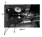
運動装置10は、座部14とハンドルバー16とを有する自転車状フレーム12を有する。座部14及びハンドルバー16の位置は調整可能であるが、トレーニングサイクル中は固定されるよう意図されている。座部14の下の足区域に、運動装置10は、足駆動ペダル18の形態の交互に作動可能な駆動要素を含む足踏み式駆動装置を含む。ペダル18は、ペダルクランク20を介して、駆動ホイール22を通って延びるペダルシャフト23(図9)によって駆動ホイール22の両側に取り付けられている。
The
フライホイールアセンブリ24は、ギヤ機構26を介して駆動ホイール22に連結されている。図1に示す実施形態では、フライホイールアセンブリ24は、図5に示すように、回転のために共通シャフト28に取り付けられた一対のフライホイール要素26を含む。
The
ギヤ機構26は、駆動ホイール22及びピニオンホイール32(図2)の周りに延びるチェーン30を含む。ペダル18の作動はペダルシャフトの回転を駆動し、ペダルシャフトは次に駆動ホイール22の回転を駆動する。駆動ホイール22は、チェーン30によってピニオンホイール32の回転を駆動し、チェーンは次にピニオンホイール32を通り、かつディスクホイール34を通って延びるシャフトを駆動し、それによりディスクホイール34の回転を駆動する。
The
ディスクホイール34は、ディスクホイール34及び共通シャフト28の周りに延びるように伸張されたベルト36(図4)によってフライホイールアセンブリ24の共通シャフト28の回転を駆動する。
The
フライホイール要素26の各々は、それと共に回転する共通軸28に取り付けられ、鋼鉄から形成されるが、磁気リム部38(図6)を形成するように銅インサートを含む。複数の永久磁石を含む制動装置40は、サーボモータ42によってフライホイール要素26の磁気リム38に向かって、及び磁気リム38から離れて移動するために取り付けられる。フライホイール要素26の磁気リム38に向かって、及び磁気リム38離れる永久磁石の移動は、永久磁石とフライホイール要素26の磁気リム38との間の磁気吸引によって生成される制動を変化させる。したがって、磁気リム38に対して永久磁石を移動させることにより、フライホイール素子26の磁気リム38に加えられる制動力を調整することが可能となり、かつそれにより、フライホイール要素26の磁気リム38と永久磁石との間の磁気吸引力によって生み出されるライホイール要素26の回転に対する抵抗を調整する。
Each of the
図5から図7に示すように、永久磁石は、ヨーク46に支持された2組の永久磁石44a、44bを形成するように取り付けられ、各組の永久磁石44a、44bは、フライホイール要素26のそれぞれ1つの磁気リム38に向かって、及び磁気リム38から離れて移動するために、ヨーク46の両側に取り付けられている。
As shown in FIGS. 5 to 7, the permanent magnets are attached so as to form two sets of
ヨーク46の移動を駆動するために、ヨーク46は、自転車状フレーム12に取り付けられた支持体50に形成されたねじ付き孔を通って延びるねじ付きシャフト48の第1の端部に取り付けられる。ねじ付きシャフト48は駆動ホイール52内の第2の端部に固定され、駆動ホイール52は次に駆動ベルト56によってサーボモータ42の従動シャフト54に連結される。
To drive the movement of the
サーボモータ42の作動は、従動シャフト54の回転を駆動し、従動シャフト54は次に、駆動ベルト56によって駆動ホイール52の回転を駆動する。支持体50に形成されたねじ付き孔内のねじ付きシャフト48の係合は、フライホイール要素26に向かって、及びフライホイール要素26から離れるように、ねじ付き開口の内外へのねじ付きシャフト48の長手方向の移動をもたらす。ねじ付きシャフト48、ひいてはヨーク46の移動方向は、サーボモータ42の従動シャフト54の回転方向、したがってねじ付きシャフト48の回転方向に依存する。
The operation of the
運動装置10は、使用時に、駆動装置を介して加えられる駆動力及びそれに関連するトルクのうちの少なくとも1つを測定するための測定ユニット58(図2)を含む。より具体的には、測定ユニット58は、自転車状フレーム12に取り付けられたアーム60を含む。駆動ホイール22及びピニオンホイール32の周りに延びるチェーン30の外縁に押しつけるために、好ましくはプラスチック材料から作られたグライド62がアーム60に取り付けられる。
The
図2に示す実施形態では、グライド62がチェーン30をわずかに内向きに押圧する。他の実施形態では、チェーン30をわずかに外向きに押圧するために、グライド62をチェーンの内側に位置決めすることができる。
In the embodiment shown in FIG. 2, the
チェーン30に張力がかかっている事象では、駆動力が使用者によって足駆動ペダル18に加えられる結果、力の接線方向の成分が、チェーン30の張力、ひいては駆動力に比例する復元力としてグライド62に作用する。アーム60の弾性曲げは、伸張測定ストリップ64によって測定される。
In an event where tension is applied to the
復元力はチェーン30の張力、ひいては駆動力に比例するので、復元力の測定値を使用して、運動装置10の作動中にペダル18に加えられる駆動力の大きさを計算することができることを理解されたい。
Since the restoring force is proportional to the tension of the
同様に、ペダルクランク20の各々の長さが分かっているので、復元力の測定値を使用して、ペダル18によって駆動ホイール22に加えられるトルクを計算することができる。
Similarly, since the length of each of the pedal cranks 20 is known, the restoring force measurements can be used to calculate the torque applied to the
力測定を較正するために、既知の大きさの質量がペダル18の1つに取り付けられ、かつフライホイール要素26またはディスクホイール34は、その回転を防止するようにロックされる。これらの条件下で測定ユニット58によって測定された力は、復元力を、ペダル18に取り付けられた既知の質量によって加えられる既知の力と比較することによって、測定ユニット58を較正することを可能にする。
To calibrate the force measurement, a mass of known magnitude is attached to one of the
この実施形態では、測定ユニット58は、運動装置10の作動中に駆動装置を介して加えられる駆動力を連続的に測定するように構成されている。連続的であることによって、測定ユニット58は、駆動装置を介して加えられる力を1秒当たり100回まで測定することが想定される。
In this embodiment, the measuring
運動装置10はまた、運動装置10の作動中にケイデンスを測定するための測定装置66(図3)を含む。
The
サイクリングの文脈において、ケイデンスは、ペダリング速度、あるいは1分当たりのペダルクランク20の回転数(RPM)を指すことを理解されたい。 It should be understood that in the context of cycling, cadence refers to pedaling speed, or the number of revolutions per minute (RPM) of the pedal crank 20.
図1に示す運動装置10の測定装置66は、図9及び図10に模式的に図示されており、駆動ホイール22に取り付けられた一対のセンサ片68と、自転車状フレーム12上の静止位置に位置決めされた一対のセンサ70とを含む。
The measuring
センサ片68とセンサ70は、駆動ホイール22の回転時に、センサ片68の各々が自転車状フレーム12に固定されたセンサ70のそれぞれ1つを通過するように互いに対して位置決めされ、それにより各センサ片68は、駆動ホイール22の回転のサイクル当たり1回だけ検出され、かつ同じセンサ70によって駆動ホイール22の回転の各サイクルで検出される。これは、駆動ホイール22ペダルシャフト上のセンサ片の半径方向距離を変化させることによって達成される。より具体的には、センサ片68の1つは、センサ片68の他方よりも駆動ホイール22上のペダルシャフトからより大きな半径方向距離に位置する。同様に、センサ70を自転車状フレーム12上に位置決めして、ペダルシャフトに対して対応する間隔をおいた場所に位置するようにすることにより、各センサ70は、駆動ホイール22の回転中にセンサ片68のうちの1つのみを検出する。
The
センサ片68とセンサ70との相対位置もまた、センサ片68が動いて180°間隔でそれぞれのセンサ70と整列するように選択され、それによりセンサ片68の各々が動いてそれぞれのセンサ70と整列する点での駆動ホイール22の動作位置は、ペダル18間の負荷交代の動作位置に対応する。
The relative position of the
したがって、駆動ホイール22の各完全な回転中に、センサ片68及びセンサ70は、180°の間隔で2つの信号を生成する。これらの信号の間の時間は、駆動ホイール22の回転速度、したがってペダリングの速度を計算するために使用することができ、一方ではケイデンスと呼ばれる。
Therefore, during each complete rotation of the
同様に、信号は180°の間隔で生成され、使用者が1つのペダルから他のペダルへの駆動力を切り替えるという点から負荷交代がある点に対応するので、センサ70を通過するセンサ片68によって生成される信号は、負荷交代の時間を指示するものと解釈することができる。
Similarly, the signals are generated at 180 ° intervals and correspond to the point of load shift in that the user switches the driving force from one pedal to the other, so that the
図9及び図10に示す実施形態では、センサ片68は磁石であり、センサ70は磁界センサである。他の実施形態では、他のセンサ片及びセンサを使用し得ると想定される。
In the embodiment shown in FIGS. 9 and 10, the
また、他の実施形態では、センサ片68の数またはセンサ70の数を変更し得ることも想定される。1つのそのような実施形態では、1つのセンサ片68を駆動ホイール22に固定してもよく、センサ片68がセンサ70の各々を180°の間隔で通過するように、センサ70を自転車状フレーム12に固定位置で取り付けてもよい。そのような一実施形態では、駆動ホイール22の回転中、センサ片68が動いて足踏み式ペダル18間の負荷交代に対応する駆動ホイール22の動作位置でセンサ70の各々と整列するように、センサ片68とセンサ70とは再び互いに対して位置してもよい。
Further, in other embodiments, it is assumed that the number of
別のそのような実施形態では、センサ片68の各々が180°の間隔でセンサ70を通過するように、一対のセンサ片68を駆動ホイール22に固定してもよく、かつ1つのセンサ70を自転車状フレーム12上に固定位置で取り付けてもよい。そのような一実施形態では、駆動ホイール22の回転中、足踏み式ペダル18間の負荷交代に対応する駆動ホイール22の動作位置でセンサ70がセンサ片68のそれぞれ1つを検出するように、センサ片68とセンサ70とは再び互いに対して位置してもよい。
In another such embodiment, the pair of
測定ユニット58及び測定装置66によって収集されたデータを照合するために、運動装置10は、コマンドモジュール72(図5)を含む。
To collate the data collected by the measuring
コマンドモジュール72は、好ましくは、運動装置の作動中にチェーン30へ加えられる駆動力を指示する信号、及び2つのペダル18間の負荷交代の時間と一緒にペダルの回転速度を受信するために、測定ユニット58及び測定装置66に接続されたプログラム可能な装置である。
The
コマンドモジュール72は、1つ以上のパフォーマンスパラメータを計算するために、測定ユニット58及び測定装置66から受信した測定値を使用するように構成されている。これらのパフォーマンスパラメータは、ケイデンス、動力、フライホイールの回転速度、ペダルに加えられる駆動力、及びそこから導出可能な他の変数を含み得る。
The
それらのパフォーマンスパラメータは、通信モジュール74に接続された使用者インターフェース(図示せず)への後続送信のために、コマンドモジュール72から通信モジュール74に送信されてもよい。しかしながら、コマンドモジュール72はまた、少なくとも1つ以上の計算されたパフォーマンスパラメータを所定のパフォーマンスプロファイルと比較するように構成されている。
These performance parameters may be transmitted from the
以下でより詳細に論じる比較結果に依存して、コマンドモジュール74はサーボモータ42に接続され、かつフライホイール要素26の磁気リム38に対して2組の永久磁石44a、44bを移動させるためにサーボモータ42を制御するように構成されている。フライホイール要素26の磁気リム38に対する2組の永久磁石44a、44bの相対位置を調整することによって、コマンドモジュール72は、2組の永久磁石44a、44bによって加えられる制動力を調整する。これは次に、フライホイール要素26の回転に対する抵抗に影響を及ぼし、したがって、測定ユニット58及び測定装置66を介して得られる測定値に影響を及ぼす。したがって、サーボモータ42の適切な制御によって、コマンドモジュール72は、コマンドモジュールによって計算された該パフォーマンスパラメータまたは各パフォーマンスパラメータを所定のパフォーマンスプロファイルと適合するように調整するために、測定ユニット58及び測定装置66から受信した測定値を微調するように作動可能である。
Depending on the comparison results discussed in more detail below, the
上記で概説したように、コマンドモジュール72は、コマンドモジュール72によって計算されたパフォーマンスパラメータを表す信号を使用者インターフェース上に表示するための外部装置に送信する目的で、通信モジュール74に接続される。
As outlined above, the
使用者のパフォーマンスを報告するフィードバック信号の形で外部装置に信号を送信するのと同時に、通信モジュール74は、コマンド信号を受信し、かつそれらの信号をコマンドモジュール72に送信するように構成されている。
At the same time as transmitting signals to external devices in the form of feedback signals reporting user performance, the
図1に示す実施形態では、通信モジュール74は、BLUETOOTH(登録商標)として知られる無線通信プロトコルを介して、コマンド信号を受信し、かつフィードバック信号を送信するように構成された無線機を含む。これにより、スマートフォン、タブレット、スマートウォッチ、または別のコンピューティング装置などの外部装置への通信モジュール74の無線接続が可能になる。
In the embodiment shown in FIG. 1, the
他の実施形態では、通信モジュール74と外部装置との間の無線データ接続を創出するために、ANT+(登録商標)などの別の無線通信プロトコルが使用され得ることが想定される。また、通信モジュール74を外部装置に接続するために、有線接続が使用され得ることも想定される。通信モジュール74は、例えば、USBケーブルのようなデータ転送ケーブルによって外部装置に接続することができる。
In other embodiments, it is envisioned that another wireless communication protocol, such as ANT +®, may be used to create a wireless data connection between the
スマートフォン、タブレット、スマートウォッチ、または他のコンピューティング装置のような外部装置への接続を容易にする通信モジュール74の提供は、ユーザインターフェースの創出を可能にする。例えば、通信モジュール74は、通信モジュール74と通信するように構成されたアプリケーションを実行するスマートフォン、タブレット、スマートウォッチ、または他のコンピューティング装置に接続することができることが想定でき、それにより所定のパフォーマンスプロファイルを創出する目的で使用者がデータを入力することを可能にする。
The provision of a
通信モジュール74はまた、装置のスクリーン上にフィードバック信号の視覚化の創出を可能にするために、そのような装置に接続することもできる。インターフェースは、例えば、ケイデンス及び/または力の測定値を表示することができる。それはまた二者択一的に、測定ユニット58及び測定装置66から得られた測定値から、コマンドモジュールによって計算された1つ以上のパフォーマンスパラメータを表示することもできる。
The
インターフェースはまた、測定装置66によって決定された負荷交代の時間、及び測定ユニット58から受信した測定値に応答してコマンドモジュール72によって計算された力測定値及びその他の変数に基づいてPOLAR VIEW(商標)を表示することもできる。時間に対する力を示すPOLAR VIEW(商標)の創出は、使用者の右肢及び左肢を具体的に参照しながら、使用者のペダリングのパフォーマンス及び技法を図示する。したがって、使用者のサイクリングパフォーマンスの視覚的印象を創出し、使用者が、自分のペダリングパフォーマンス及び/または技法が改善を必要とする可能性のある場所を視覚的に決定することを可能にする。
The interface is also POLAR VIEW ™ based on the load change time determined by the measuring
POLAR VIEW(商標)の一例を図8に示す。 An example of POLAR VIEW ™ is shown in FIG.
運動装置10の作動についてここで説明する。
The operation of the
運動装置10の作動中、使用者はペダル18の作動を介してフライホイール要素26の回転を駆動する。上で概説したように、駆動ホイール22の周りに伸びるチェーンに加わる結果として生じる駆動力は、測定ユニット58によって連続的に測定され、その結果の測定値はコマンドモジュール72に送信される。
During the operation of the
同様に、ケイデンスまたはペダリングの速度は、測定装置66によって測定され、その結果の測定値は、ペダル18間の負荷交代の時間を指示する信号と一緒にコマンドモジュール72に送信される。
Similarly, the cadence or pedaling speed is measured by the measuring
コマンドモジュール72は、測定装置58及び測定装置66から受信した測定値及び信号を使用して、使用者の動力出力を計算する。
The
コマンドユニット72は、好ましくは、動力=力×速度に基づいてペダルクランク20の1回転につき1回の使用者の動力出力を計算し、測定されたケイデンス及びペダルクランク20の1回転当たりの走行距離を参照して速度を計算することができる。上記で概説したように、ペダルクランク20の1回転当たりの走行距離は、一連のプリセットギヤに従ってコマンドモジュール内でプリセットされ得る。コマンドモジュール72は、実際の自転車のギヤチェンジ時にサイクリストが経験するであろう付加的抵抗をシミュレートするために、使用者によるより高いギヤの選択時にフライホイール24に加えられる制動力を増加させるように構成されてもよく、その逆でもよい。同様に、コマンドモジュール72は、ペダルクランク20の1回転当たりの走行距離を、最低ギヤから最高ギヤまでの各ギヤで徐々に増加するように構成されてもよく、またその逆でもよい。
The
特に好ましい実施形態では、以下の表1に提示されるように、1回転あたりの走行距離は、ボトムギヤ、ギヤ1、の最小値2.790mからトップギヤ、ギヤ22、の最大値10.258mまで徐々に増加する。

そのような実施形態では、ギヤ1の運動装置を毎分60回転のケイデンスで作動させる使用者は、2.790ms−1の速度に等しくなると理解されたい。 In such an embodiment, it should be understood that a user operating a gear 1 motor with a cadence of 60 revolutions per minute would be equal to a speed of 2.790 ms-1.
使用者がギヤを上下に変更することを可能にするために、ボタン(図示せず)が、ハンドルバー16に含まれてもよい。その結果、実際の自転車に乗っているかのように、使用者がギヤを容易に上下させることが可能になる。そのようなボタンは、必要な信号を提供するためにコマンドモジュール72宛に接続されてもよく、好ましくはギヤを上げるための1つのボタンと、ギヤを下げるための第2ボタンとを含む。
Buttons (not shown) may be included in the
他の実施形態では、ボタンは、コマンドモジュール72への後続送信のために通信モジュール74にコマンド信号を送るように構成されてもよい。
In other embodiments, the button may be configured to send a command signal to the
コマンドユニット72はまた、通信モジュール74を介して、ユーザインターフェースを提供するために通信モジュール74に接続された外部装置へ送信するための駆動力から導出される他のパフォーマンスパラメータまたは変数を計算してもよい。
The
その最も単純な形態では、使用者が運動装置10の作動中に定動力出力を達成することを保証することを目指して、使用者は、コマンドモジュール72内に所定のパフォーマンスプロファイルを創出してもよい。これは、使用者の実際の動力出力を計算するためにケイデンス及び力測定値を使用し、計算された動力を所定のパフォーマンスプロファイルによって要求される動力出力値比較し、同じケイデンスで必要な動力出力を達成するために使用者がペダルにより大きいまたはより小さい力を加えることを要求するように制動力を増減させるためにモータを制御することによって達成されてもよい。
In its simplest form, the user may create a given performance profile within the
使用者はまた、トレーニングプログラムを開始する前に、一連の所定のパフォーマンスプロファイルから選択してもよい。例えば、使用者は、特定のギヤに対する動力とケイデンスとの間の曲線関係を定義する所定のパフォーマンスプロファイルを選択することができる。その後、運動装置10の作動時に、コマンドモジュール72は、使用者の実際の動力出力を計算するためにケイデンス及び力測定値を使用し、ケイデンス測定値と一緒に計算された動力値を、所定のパフォーマンスプロファイルによって定義される動力とケイデンスとの間の曲線関係と比較する。
The user may also choose from a set of predetermined performance profiles before starting the training program. For example, the user can select a given performance profile that defines the curvilinear relationship between power and cadence for a particular gear. Then, when the
この比較を実行すると、コマンドモジュール72は、使用者の実際の動力出力が、測定されたケイデンスに対して所定のパフォーマンスプロファイルによって要求されるよりも高いか低いかを判定することができ、サーボモータ42を作動させて、フライホイール要素26上の永久磁石44a、44bの組によって加えられる制動力を調整するようにフライホイール要素26に対する永久磁石44a、44bの組の相対位置を調整する。これは次に、同じケイデンスでペダルを駆動するために使用者から求められる駆動力を増減少させ、使用者の計算された動力出力が、測定されたケイデンスについての所定のパフォーマンスプロファイルによって要求される動力に適合するように、測定ユニット58及び測定装置66から得られる測定値を微調するために使用することができる。
Performing this comparison allows the
図に示された実施形態では、コマンドモジュール72はまた、通信モジュール74からのコマンド信号の形式でパフォーマンス特性データを受信すると、所定のパフォーマンスプロファイルを計算するように構成されている。
In the embodiment shown in the figure, the
これは、使用者が、一連のサイクリングパラメータを通信モジュール74に接続された外部装置に入力することを可能にし、それは次に、通信モジュール74を介してコマンドモジュール72に通信され、コマンドモジュール72が、選択されたサイクルパラメータに基づいて個別化された所定のパフォーマンスプロファイルを計算することを可能にする。
This allows the user to input a set of cycling parameters to an external device connected to the
パフォーマンス特性データは、サイクリング面の傾斜角、自転車タイヤとサイクリング面との間の転がり抵抗、サイクリストの質量、自転車の質量、及びサイクリストの動力出力からなる群から選択される1つ以上の静的サイクリングパラメータに関する情報を含んでもよい。 Performance characteristic data is one or more static cycling selected from the group consisting of the angle of inclination of the cycling surface, the rolling resistance between the bicycle tire and the cycling surface, the mass of the cyclist, the mass of the bicycle, and the power output of the cyclist. It may contain information about the parameters.
パフォーマンス特性データはまた、風速の変化によって生み出される空気抵抗、高度の変化によって生み出される空気抵抗、及びファンの使用を介して生み出される空気抵抗からなる群から選択される1つ以上の動的サイクリングパラメータに関する情報を含んでもよい。 Performance characteristic data is also one or more dynamic cycling parameters selected from the group consisting of air resistance produced by changes in wind speed, air resistance produced by changes in altitude, and air resistance produced through the use of fans. May include information about.
通信モジュール74を介して受信されるコマンド信号の形態で、外部装置からこの情報を受信すると、コマンドモジュール72は、サイクリストがそれらの条件下で自転車に乗って経験する抗力上の任意の選択されたサイクリングパラメータの影響を計算するように構成されている。これは次に、コマンドモジュール72が追加の抗力を考慮して所定のパフォーマンスプロファイルを計算することを可能にする。
Upon receiving this information from an external device in the form of a command signal received via the
ペダルクランク20の1回転当たりの走行距離が、上記表1に提示の一連のプリセットギヤに従ってコマンドモジュール内にプリセットされている特に好ましい実施形態では、コマンドモジュールは、以下の表2に提示するように、プリセットされたギヤセット及び例示的なケイデンス数字に従って、傾斜がなく、風力抵抗ゼロの平坦道路上をサイクリングする70kgの体重の使用者よって生み出される抗力を克服するために求められる付加的な力を計算する。
使用者がそのような条件下で自転車に乗っていた場合に創出される抗力は、各ギヤにおける使用者のケイデンス、したがって自転車の走行速度と共に増加することを理解されたい。 It should be understood that the drag created when the user is riding the bicycle under such conditions increases with the user's cadence in each gear, and thus the running speed of the bicycle.
コマンドモジュールによって計算された、ケイデンスの漸進的増加に対してギヤ1、10、及び22において増加する抗力を克服するために必要な動力の例を、以下の表3、4、及び5に示す。
コマンドモジュール72は、例えば、選択されたサイクリングパラメータの結果として経験する抗力を考慮して計算される動力出力対ケイデンスに基づいて所定のパフォーマンスプロファイルを生成することができる。これは、必要な抗力を生み出し、かつそれによって様々なサイクリング条件をシミュレートするために、コマンドモジュール72が、サーボモータ42を制御し、かつそれによってフライホイール要素26の磁気リム38に対する永久磁石44a、44bの組の移動を制御することを可能にする。
The
サイクリングパラメータの適切な選択によって、使用者は、サイクリング条件の無限数の組み合わせをシミュレートするようにコマンドモジュール72に命令するコマンド信号を生み出し得る。例えば、コマンドモジュール72は、競輪場の面を軽自転車に乗っている軽サイクリスト、ダートトラック上の同じサイクリスト及び自転車、5°の傾斜面上の同じサイクリスト及び自転車、毎時10マイルの後ろ風を有する−5°の傾斜面上の同じサイクリスト及び自転車、をシミュレートすることができる。
With proper selection of cycling parameters, the user may generate a command signal instructing the
コマンドモジュール72はまた、例えば、様々な位置を取り、かつそれによりファンの回転を駆動するためのペダルの作動時にファンを通って流れる空気流に影響を及ぼしかつ制御するように調整することができる、ファンの外側ハウジング上に通気孔を備えたファンを有する定置式エルゴメトリック運動装置をシミュレートすることもできる。
The
上記の動的サイクリングパラメータを参照すると、そのような条件下でサイクリストが経験する抗力は、流体力学の結果として速度に応じて変化する。したがって、コマンドモジュール72は、フライホイール要素26の回転速度、または同じケイデンスで、かつ同じ駆動力で作動される実際の自転車の等価速度を計算するために測定装置58から受信した測定値を使用するように構成され得る。
With reference to the dynamic cycling parameters above, the drag experienced by cyclists under such conditions varies with velocity as a result of fluid dynamics. Therefore, the
現実の自転車の速度は、上記で概説したように、測定されたケイデンス及びペダルクランク20の1回転当たりの走行距離を参照して計算することができる。 The actual bicycle speed can be calculated with reference to the measured cadence and mileage per revolution of the pedal crank 20, as outlined above.
フライホイール要素26の回転速度はまた、所定のパフォーマンスプロファイルを調整するためにコマンドモジュール72によって使用されるかまたは代替的に使用され得る自転車の実際の速度を指示し、それにより所定のパフォーマンスプロファイルの計算に採用される1つ以上の動的サイクリングパラメータに使用者の速度の影響を反映させる。
The rotational speed of the
他の実施形態では、外部装置は、特定のサイクリングルートをシミュレートするためのコマンド信号を生成するために使用することができるサイクリングルートに関するデータを含み得る。データは、例えば、ツールドフランスの特定のステージまたはオリンピックロードレースルートに関係する場合がある。 In other embodiments, the external device may include data about a cycling route that can be used to generate command signals to simulate a particular cycling route. The data may relate, for example, to a particular stage in the Tour de France or the Olympic road race route.
そのような実施形態では、コマンドモジュール72は、選択されたルートの特性に係るコマンド信号に基づいて所定のパフォーマンスプロファイルを生成するように構成されてもよい。このような特性は、傾斜角、自転車タイヤとサイクリング面との間の転がり抵抗、及び高度を含んでもよい。それらはまた、選択されたルートに沿って以前に記録された走行の正確な条件をシミュレートするために、使用者が選択する事象における、風速、風向き、及び他の天候特性を含むことができる。
In such an embodiment, the
シミュレーション中に、コマンドモジュール72は、上記で概説した方法に従って、使用者の動力出力を計算し、かつ使用者の測定されたケイデンスで必要とされる動力出力を決定するために所定のパフォーマンスプロファイルと比較する。これは、要求される動力出力を達成し、かつそれにより、選択されたギヤにおいて、及び使用者によって到達されるルートに沿った位置で、そのケイデンスで使用者が経験するであろうペダルへの抵抗をシミュレートするように、コマンドモジュール72が、サーボモータ42を制御し、かつそれによって測定ユニット58及び測定装置66から受信した測定値を微調するためにフライホイール要素26の磁気リム38に対する永久磁石44a、44bの組の移動を制御することを可能にする。
During simulation, the
選択されたルートに関するデータは、通信モジュール74を介して外部装置から単一送信の形態で提供することができることを理解されたい。しかしながらまた、より詳細で正確なシミュレーションを提供するために、より多くのデータの提供を可能にし、こうして所定のパフォーマンスプロファイルの進行中の調整を容易にするために、選択されたルートのシミュレーション中に、データは、通信モジュール74を介して外部装置からコマンドモジュール72へ連続的にストリームできることを理解されたい。
It should be appreciated that data about the selected route can be provided in the form of a single transmission from an external device via the
いずれにしても、コマンドモジュール72は、通信モジュール74を介して外部装置にフィードバック信号を送り返してもよく、それは外部装置が選択されたルートに沿った使用者の進捗状況を追跡することを可能にする。これは外部装置の信号に変換することができ、それは、外部装置が、使用者が選択されたルートに沿って彼らの行程を視覚化することを可能にするであろうビデオ画像を生成することを可能にする。
In any case, the
Claims (26)
ペダルクランクを介して駆動ホイールの両側に取り付けられた足駆動ペダルの形態の交互に作動可能な駆動要素を含む足踏み式駆動装置と、
ギヤ機構を介して前記駆動ホイールに連結されたフライホイールであって、前記フライホイールは磁気リムを含む、フライホイールと、
1つ以上の永久磁石によって前記フライホイールに加えられる制動力を選択的に調整するように、モータによって前記フライホイールの前記磁気リムに向かって、及び前記磁気リムから離れて移動するために取り付けられた前記1つ以上の永久磁石の形態の制動装置と、
使用時に、前記駆動装置を介して加えられる駆動力及びそれに関連するトルクのうちの少なくとも1つを測定する測定ユニットと、
使用時に、ケイデンスを測定するための測定装置と、
前記測定ユニット、前記測定装置、及び前記制動装置の前記モータに接続されたコマンドモジュールと、
前記コマンドモジュールに接続され、かつコマンド信号を受信し、それらのコマンド信号を前記コマンドモジュールに送信するように構成され、かつ前記コマンドモジュールから受信した使用者のパフォーマンスを報告するフィードバック信号を送信するように構成された、通信モジュールと、を備え、
前記コマンドモジュールは、前記通信モジュールから前記コマンド信号の形態でパフォーマンス特性データを受信すると、所定のパフォーマンスプロファイルを計算するように構成され、
前記コマンドモジュールは、前記測定ユニット及び前記測定装置から測定値を受信し、これらの測定値を使用して使用者の動力出力を計算し、前記使用者の動力出力を前記所定のパフォーマンスプロファイルと比較して前記使用者の前記測定されたケイデンスで必要とされる前記動力出力を決定し、前記1つ以上の永久磁石によって加えられる前記制動力を調整するために、前記モータを制御して前記1つ以上の永久磁石を前記フライホイールの前記磁気リムに対して移動させ、それにより前記測定ユニット及び前記測定装置から受信した前記測定値を微調して、前記コマンドモジュールによって計算された、前記使用者の前記測定されたケイデンスでの動力出力を、前記所定のパフォーマンスプロファイルに適合するように調整するように構成されている、定置式エルゴメトリック運動装置。 It is a stationary ergometric exercise device.
A foot-operated drive that includes alternating actuable drive elements in the form of foot-drive pedals mounted on both sides of the drive wheel via a pedal crank.
A flywheel connected to the drive wheel via a gear mechanism, wherein the flywheel includes a magnetic rim and a flywheel.
Attached by a motor to move towards and away from the magnetic rim of the flywheel by a motor so as to selectively adjust the braking force applied to the flywheel by one or more permanent magnets. And the braking device in the form of one or more permanent magnets,
A measuring unit that measures at least one of the driving force applied through the driving device and its associated torque during use.
A measuring device for measuring cadence during use,
A command module connected to the measuring unit, the measuring device, and the motor of the braking device.
Connected to the command module, received command signals, configured to send those command signals to the command module, and to send a feedback signal reporting user performance received from the command module. It is equipped with a communication module, which is configured in
The command module is configured to calculate a predetermined performance profile upon receiving performance characteristic data in the form of the command signal from the communication module.
The command module receives measurements from the measuring unit and the measuring device, calculates the user's power output using these measurements, and compares the user's power output with the predetermined performance profile. The motor is controlled to determine the power output required for the measured cadence of the user and to adjust the braking force applied by the one or more permanent magnets. The user calculated by the command module by moving one or more permanent magnets with respect to the magnetic rim of the flywheel, thereby fine-tuning the measured values received from the measuring unit and the measuring device. A stationary ergometric exercise device configured to adjust the power output at the measured cadence of the above to fit the predetermined performance profile.
パフォーマンス特性データを入力し、前記パフォーマンス特性データに基づいて所定のパフォーマンスプロファイルを計算するステップと、
前記測定ユニット及び測定装置から受信した測定値を使用して使用者の動力出力を計算するステップと、
前記使用者の前記計算された動力出力を前記所定のパフォーマンスプロファイルと比較して、前記使用者の前記測定されたケイデンスで必要とされる前記動力出力を決定するステップと、
前記1つ以上の永久磁石によって加えられる前記制動力を調整するために、前記モータを制御して前記1つ以上の永久磁石を前記フライホイールの前記磁気リムに対して移動させ、それにより前記測定ユニット及び前記測定装置から受信した前記測定値を微調して、コマンドモジュールによって計算された、前記使用者の前記測定されたケイデンスでの動力出力を、前記所定のパフォーマンスプロファイルに適合するように調整するステップと、を含む、定置式エルゴメトリック運動装置の作動方法。 A foot-operated drive with alternating actuable drive elements in the form of foot drive pedals mounted on both sides of the drive wheel via a crank, and a flywheel connected to the drive wheel via a gear mechanism. , The flywheel includes a magnetic rim, towards the magnetic rim of the flywheel by a motor so as to selectively adjust the braking force applied to the flywheel by the flywheel and one or more permanent magnets. , And a braking device in the form of one or more permanent magnets attached to move away from the magnetic rim, and at least of the driving force and associated torque applied through the driving device during use. A method of operating a stationary ergometric exercise device, including a measuring unit for measuring one and a measuring unit for measuring cadence when in use.
A step of inputting performance characteristic data and calculating a predetermined performance profile based on the performance characteristic data.
The step of calculating the power output of the user using the measured values received from the measuring unit and the measuring device, and
A step of comparing the calculated power output of the user with the predetermined performance profile to determine the power output required for the measured cadence of the user.
In order to adjust the braking force applied by the one or more permanent magnets, the motor is controlled to move the one or more permanent magnets with respect to the magnetic rim of the flywheel, thereby the measurement. The measured values received from the unit and the measuring device are fine-tuned to adjust the power output of the user at the measured cadence calculated by the command module to fit the predetermined performance profile. How to operate a stationary ergometric exercise device, including steps.
Applications Claiming Priority (3)
| Application Number | Priority Date | Filing Date | Title |
|---|---|---|---|
| GB1600466.5A GB2546113A (en) | 2016-01-11 | 2016-01-11 | Stationary ergometric exercise device |
| GB1600466.5 | 2016-01-11 | ||
| PCT/GB2017/050062 WO2017122007A1 (en) | 2016-01-11 | 2017-01-11 | Stationary ergometric exercise device |
Publications (3)
| Publication Number | Publication Date |
|---|---|
| JP2019501002A JP2019501002A (en) | 2019-01-17 |
| JP2019501002A5 JP2019501002A5 (en) | 2021-05-20 |
| JP6989520B2 true JP6989520B2 (en) | 2022-01-05 |
Family
ID=55445829
Family Applications (1)
| Application Number | Title | Priority Date | Filing Date |
|---|---|---|---|
| JP2018555312A Active JP6989520B2 (en) | 2016-01-11 | 2017-01-11 | Stationary ergometric exercise device |
Country Status (16)
| Country | Link |
|---|---|
| US (2) | US11235198B2 (en) |
| EP (1) | EP3402579B1 (en) |
| JP (1) | JP6989520B2 (en) |
| CN (1) | CN108883334B (en) |
| AU (1) | AU2017208029B2 (en) |
| BR (1) | BR112018014162A2 (en) |
| CA (1) | CA3010766C (en) |
| DK (1) | DK3402579T3 (en) |
| ES (1) | ES2885831T3 (en) |
| GB (1) | GB2546113A (en) |
| PL (1) | PL3402579T3 (en) |
| PT (1) | PT3402579T (en) |
| RU (1) | RU2729088C1 (en) |
| TW (1) | TWI718229B (en) |
| WO (1) | WO2017122007A1 (en) |
| ZA (1) | ZA201805335B (en) |
Families Citing this family (11)
| Publication number | Priority date | Publication date | Assignee | Title |
|---|---|---|---|---|
| CZ307852B6 (en) * | 2017-05-24 | 2019-06-26 | Technická univerzita v Liberci | Rehabilitation ergometer and its control |
| FR3074712B1 (en) | 2017-12-13 | 2020-07-31 | Innovation Fabrication Commercialisation Infaco | ELECTRO PORTABLE MOTORIZED PRUNER EQUIPPED WITH A MORE ERGONOMIC AND SAFE SAFETY DEVICE. |
| GB201810397D0 (en) * | 2018-06-25 | 2018-08-08 | Wattbike Ip Ltd | Method and apparartus for monitoring user effectivness during operation of an exercise machine |
| EP3679995B1 (en) * | 2019-01-14 | 2021-07-21 | Emotion Fitness GmbH & Co. KG | Stationary exercise device |
| CN109908551B (en) * | 2019-02-02 | 2022-02-15 | 随机漫步(上海)体育科技有限公司 | Bicycle exercise method and device |
| US20220273772A1 (en) * | 2019-07-26 | 2022-09-01 | Pandorum Technologies Private Limited | Bioengineered formulation, process for preparing and implementations thereof |
| BR112022018552A2 (en) * | 2020-04-23 | 2022-11-01 | Dynamic Accession LLC | DYNAMIC MOVEMENT RESISTANCE MODULE |
| TWI774062B (en) * | 2020-09-15 | 2022-08-11 | 緯創資通股份有限公司 | Training device |
| CN114129955B (en) * | 2021-07-12 | 2023-06-20 | 宁波篆和科技有限公司 | Resistance-adjustable rotating wheel, adjusting method thereof and sports equipment |
| CN114272559B (en) * | 2021-12-28 | 2023-03-24 | 青岛迈金智能科技股份有限公司 | Intelligent riding device and power calculation method thereof |
| TWI790900B (en) * | 2022-01-17 | 2023-01-21 | 志合訊息股份有限公司 | Speed generation method for simulating riding |
Family Cites Families (34)
| Publication number | Priority date | Publication date | Assignee | Title |
|---|---|---|---|---|
| CH521585A (en) | 1968-06-18 | 1972-04-15 | Projektovy Ustav Dopravnich A | Method for registering deformations and device for its implementation |
| US4938475A (en) | 1987-05-26 | 1990-07-03 | Sargeant Bruce A | Bicycle racing training apparatus |
| JPH044765Y2 (en) * | 1987-12-29 | 1992-02-12 | ||
| JPH079363U (en) * | 1993-07-29 | 1995-02-10 | レアオ,ワン | Exercise Bike Magnetic Resistance Adjuster |
| RU2081645C1 (en) * | 1993-12-27 | 1997-06-20 | Владимир Дмитриевич Болотов | Bicycle-type training apparatus |
| JP3009143U (en) * | 1994-07-26 | 1995-03-28 | グリーンマスター インダストリアル コーポレイション | Magnetic control device that automatically controls the magnetic tension according to the setting of the watt value that represents momentum |
| US20030073546A1 (en) * | 2001-09-28 | 2003-04-17 | Lassanske Todd W. | Self-powered variable resistance bicycle trainer |
| US6726586B2 (en) | 2001-11-09 | 2004-04-27 | Shimano Inc. | Motorized bicycle actuator assembly |
| JP2003231491A (en) | 2002-02-08 | 2003-08-19 | Sunstar Eng Inc | Power-assisted bicycle providing aerobic exercise |
| CN1247284C (en) * | 2003-05-27 | 2006-03-29 | 李明 | Method and apparatus for realizing virtual riding bicycle |
| CN2675543Y (en) * | 2004-01-29 | 2005-02-02 | 黄岩 | Sensing device for intelligent electric bicycle |
| US7648446B2 (en) * | 2004-06-09 | 2010-01-19 | Unisen, Inc. | System and method for electronically controlling resistance of an exercise machine |
| US20060234840A1 (en) * | 2005-03-23 | 2006-10-19 | Watson Edward M | Closed loop control of resistance in a resistance-type exercise system |
| GB0515929D0 (en) * | 2005-08-03 | 2005-09-07 | Loach Andrew R | Exercise machine |
| NO20055233D0 (en) * | 2005-11-08 | 2005-11-08 | Kalifen As | Indoor exercise bike with tilt function |
| TWM295528U (en) * | 2006-02-10 | 2006-08-11 | Yun-Ting Chiou | Resistance device of magnetically controlled flywheel for indoor exercising equipment |
| CN100588588C (en) | 2006-11-15 | 2010-02-10 | 赵正康 | Electric bicycle |
| DK2183034T3 (en) * | 2007-08-30 | 2011-05-23 | Wilson Ian John | Ergometric training device |
| US20100035726A1 (en) * | 2008-08-07 | 2010-02-11 | John Fisher | Cardio-fitness station with virtual-reality capability |
| WO2010105223A1 (en) * | 2009-03-13 | 2010-09-16 | Nautilus, Inc. | Exercise bike |
| TW201103602A (en) * | 2009-07-27 | 2011-02-01 | Footwear & Recreation Technology Res Inst | Exercise bike with speed control system |
| ES2379450B1 (en) * | 2010-10-01 | 2013-03-01 | Bkool, S.L. | SPORTS TRAINING DEVICE. |
| US9468794B2 (en) * | 2011-09-01 | 2016-10-18 | Icon Health & Fitness, Inc. | System and method for simulating environmental conditions on an exercise bicycle |
| CN102363068A (en) * | 2011-11-17 | 2012-02-29 | 河南理工大学 | Fitness bicycle |
| DE102012019338A1 (en) * | 2012-10-02 | 2014-04-03 | Andreas Fischer | Stationary exercise bike |
| CN104884137B (en) | 2012-12-12 | 2018-06-05 | 迈克尔·弗莱贝格 | Cycle training device |
| US9868028B2 (en) * | 2013-09-04 | 2018-01-16 | Considerc Inc. | Virtual reality indoor bicycle exercise system using mobile device |
| TWD163790S (en) | 2013-10-31 | 2014-10-21 | 好吉康健美科技有限公司 | Exercise bike |
| CN103920287B (en) * | 2014-05-06 | 2017-01-11 | 许昌学院 | Virtual scene network exercise bicycle |
| TWD167127S (en) | 2014-07-22 | 2015-04-11 | 朗美(廈門)健身器材有限 | exercise bike |
| CN105056475A (en) * | 2015-07-17 | 2015-11-18 | 南京空山新雨环保科技有限公司 | Exercise bike having motion sensing game function |
| CN108348803A (en) * | 2015-08-25 | 2018-07-31 | 卫图里发展有限责任公司 | Fixation fitness equipment for Spinning |
| NL2016180B1 (en) * | 2016-01-28 | 2017-08-01 | Tacx Roerend En Onroerend Goed B V | Bicycle trainer and method of its operation. |
| IT201600083062A1 (en) * | 2016-08-05 | 2018-02-05 | Technogym Spa | Exercise equipment for cycling simulation and its method of operation. |
-
2016
- 2016-01-11 GB GB1600466.5A patent/GB2546113A/en not_active Withdrawn
-
2017
- 2017-01-11 EP EP17704522.6A patent/EP3402579B1/en active Active
- 2017-01-11 ES ES17704522T patent/ES2885831T3/en active Active
- 2017-01-11 WO PCT/GB2017/050062 patent/WO2017122007A1/en active Application Filing
- 2017-01-11 AU AU2017208029A patent/AU2017208029B2/en active Active
- 2017-01-11 CA CA3010766A patent/CA3010766C/en active Active
- 2017-01-11 PL PL17704522T patent/PL3402579T3/en unknown
- 2017-01-11 US US16/069,229 patent/US11235198B2/en active Active
- 2017-01-11 PT PT177045226T patent/PT3402579T/en unknown
- 2017-01-11 BR BR112018014162A patent/BR112018014162A2/en not_active Application Discontinuation
- 2017-01-11 JP JP2018555312A patent/JP6989520B2/en active Active
- 2017-01-11 TW TW106100828A patent/TWI718229B/en active
- 2017-01-11 CN CN201780012248.1A patent/CN108883334B/en active Active
- 2017-01-11 DK DK17704522.6T patent/DK3402579T3/en active
- 2017-01-11 RU RU2018129171A patent/RU2729088C1/en active
-
2018
- 2018-08-10 ZA ZA2018/05335A patent/ZA201805335B/en unknown
-
2021
- 2021-11-30 US US17/457,018 patent/US11565149B2/en active Active
Also Published As
| Publication number | Publication date |
|---|---|
| RU2729088C1 (en) | 2020-08-04 |
| TW201738542A (en) | 2017-11-01 |
| GB201600466D0 (en) | 2016-02-24 |
| EP3402579B1 (en) | 2021-06-02 |
| GB2546113A (en) | 2017-07-12 |
| ES2885831T3 (en) | 2021-12-15 |
| CN108883334A (en) | 2018-11-23 |
| BR112018014162A2 (en) | 2018-12-11 |
| US20190046834A1 (en) | 2019-02-14 |
| CA3010766A1 (en) | 2017-07-20 |
| ZA201805335B (en) | 2021-03-31 |
| PL3402579T3 (en) | 2022-02-14 |
| JP2019501002A (en) | 2019-01-17 |
| WO2017122007A1 (en) | 2017-07-20 |
| CA3010766C (en) | 2023-03-21 |
| PT3402579T (en) | 2021-09-07 |
| NZ745142A (en) | 2021-09-24 |
| US11235198B2 (en) | 2022-02-01 |
| DK3402579T3 (en) | 2021-09-13 |
| US20220080255A1 (en) | 2022-03-17 |
| CN108883334B (en) | 2022-01-11 |
| US11565149B2 (en) | 2023-01-31 |
| AU2017208029A1 (en) | 2018-08-30 |
| EP3402579A1 (en) | 2018-11-21 |
| TWI718229B (en) | 2021-02-11 |
| AU2017208029B2 (en) | 2021-09-09 |
Similar Documents
| Publication | Publication Date | Title |
|---|---|---|
| JP6989520B2 (en) | Stationary ergometric exercise device | |
| EP3448533B1 (en) | Exercise equipment and exercise equipment assembly, and apparatus and method for simulating exercise environment in exercise equipment | |
| JP2019501002A5 (en) | ||
| US7648446B2 (en) | System and method for electronically controlling resistance of an exercise machine | |
| US7833135B2 (en) | Stationary exercise equipment | |
| EP1514583B1 (en) | Exercise apparatus | |
| US20050209056A1 (en) | Elliptical step distance measurement | |
| US20090264257A1 (en) | Stride adjustment mechanism | |
| JP2010536508A5 (en) | ||
| KR20070043325A (en) | Treadmill system | |
| TWI626189B (en) | Power sensing system for bicycles | |
| AU2019293144B2 (en) | Method and apparatus for monitoring user effectiveness during operation of an exercise machine | |
| NZ745142B2 (en) | Stationary ergometric exercise device | |
| US20230302326A1 (en) | Method of controlling a force and/or resistance generator of an exercise apparatus | |
| GB2610224A (en) | An exercise bike system | |
| KR101995810B1 (en) | Electric Bicycle | |
| NL2004512C2 (en) | Bicycle trainer. | |
| KR20200078267A (en) | A personalized bicycle flame production system using the analysis algorithm for exercise | |
| KR20140005375U (en) | indoor bicycle exercise device |
Legal Events
| Date | Code | Title | Description |
|---|---|---|---|
| A621 | Written request for application examination |
Free format text: JAPANESE INTERMEDIATE CODE: A621 Effective date: 20191212 |
|
| A131 | Notification of reasons for refusal |
Free format text: JAPANESE INTERMEDIATE CODE: A131 Effective date: 20210112 |
|
| A524 | Written submission of copy of amendment under article 19 pct |
Free format text: JAPANESE INTERMEDIATE CODE: A524 Effective date: 20210409 |
|
| A131 | Notification of reasons for refusal |
Free format text: JAPANESE INTERMEDIATE CODE: A131 Effective date: 20210629 |
|
| A521 | Request for written amendment filed |
Free format text: JAPANESE INTERMEDIATE CODE: A523 Effective date: 20210831 |
|
| TRDD | Decision of grant or rejection written | ||
| A01 | Written decision to grant a patent or to grant a registration (utility model) |
Free format text: JAPANESE INTERMEDIATE CODE: A01 Effective date: 20211005 |
|
| A601 | Written request for extension of time |
Free format text: JAPANESE INTERMEDIATE CODE: A601 Effective date: 20211025 |
|
| A61 | First payment of annual fees (during grant procedure) |
Free format text: JAPANESE INTERMEDIATE CODE: A61 Effective date: 20211202 |
|
| R150 | Certificate of patent or registration of utility model |
Ref document number: 6989520 Country of ref document: JP Free format text: JAPANESE INTERMEDIATE CODE: R150 |