RU2727632C2 - Replaceable end milling head with an integral threaded section for connection with shank - Google Patents
Replaceable end milling head with an integral threaded section for connection with shank Download PDFInfo
- Publication number
- RU2727632C2 RU2727632C2 RU2018139518A RU2018139518A RU2727632C2 RU 2727632 C2 RU2727632 C2 RU 2727632C2 RU 2018139518 A RU2018139518 A RU 2018139518A RU 2018139518 A RU2018139518 A RU 2018139518A RU 2727632 C2 RU2727632 C2 RU 2727632C2
- Authority
- RU
- Russia
- Prior art keywords
- shank
- milling head
- cutting
- head
- ldr
- Prior art date
Links
Images
Classifications
-
- B—PERFORMING OPERATIONS; TRANSPORTING
- B23—MACHINE TOOLS; METAL-WORKING NOT OTHERWISE PROVIDED FOR
- B23C—MILLING
- B23C5/00—Milling-cutters
- B23C5/02—Milling-cutters characterised by the shape of the cutter
- B23C5/10—Shank-type cutters, i.e. with an integral shaft
-
- B—PERFORMING OPERATIONS; TRANSPORTING
- B23—MACHINE TOOLS; METAL-WORKING NOT OTHERWISE PROVIDED FOR
- B23B—TURNING; BORING
- B23B31/00—Chucks; Expansion mandrels; Adaptations thereof for remote control
- B23B31/02—Chucks
- B23B31/10—Chucks characterised by the retaining or gripping devices or their immediate operating means
- B23B31/11—Retention by threaded connection
- B23B31/1107—Retention by threaded connection for conical parts
- B23B31/1115—Retention by threaded connection for conical parts using conical threads
-
- B—PERFORMING OPERATIONS; TRANSPORTING
- B23—MACHINE TOOLS; METAL-WORKING NOT OTHERWISE PROVIDED FOR
- B23C—MILLING
- B23C5/00—Milling-cutters
- B23C5/28—Features relating to lubricating or cooling
-
- B—PERFORMING OPERATIONS; TRANSPORTING
- B23—MACHINE TOOLS; METAL-WORKING NOT OTHERWISE PROVIDED FOR
- B23C—MILLING
- B23C2210/00—Details of milling cutters
- B23C2210/02—Connections between the shanks and detachable cutting heads
-
- B—PERFORMING OPERATIONS; TRANSPORTING
- B23—MACHINE TOOLS; METAL-WORKING NOT OTHERWISE PROVIDED FOR
- B23C—MILLING
- B23C2210/00—Details of milling cutters
- B23C2210/03—Cutting heads comprised of different material than the shank irrespective of whether the head is detachable from the shank
-
- B—PERFORMING OPERATIONS; TRANSPORTING
- B23—MACHINE TOOLS; METAL-WORKING NOT OTHERWISE PROVIDED FOR
- B23C—MILLING
- B23C2210/00—Details of milling cutters
- B23C2210/04—Angles
- B23C2210/0407—Cutting angles
- B23C2210/0442—Cutting angles positive
- B23C2210/0457—Cutting angles positive radial rake angle
-
- B—PERFORMING OPERATIONS; TRANSPORTING
- B23—MACHINE TOOLS; METAL-WORKING NOT OTHERWISE PROVIDED FOR
- B23C—MILLING
- B23C2210/00—Details of milling cutters
- B23C2210/54—Configuration of the cutting part
-
- B—PERFORMING OPERATIONS; TRANSPORTING
- B23—MACHINE TOOLS; METAL-WORKING NOT OTHERWISE PROVIDED FOR
- B23C—MILLING
- B23C2250/00—Compensating adverse effects during milling
- B23C2250/12—Cooling and lubrication
Abstract
Description
ОБЛАСТЬ ТЕХНИКИ, К КОТОРОЙ ОТНОСИТСЯ ИЗОБРЕТЕНИЕTECHNICAL FIELD OF THE INVENTION
[001] Настоящая заявка относится к сменным фрезерным головкам и, в частности, к сменным фрезерным головкам, обеспеченным по меньшей мере одной осевой режущей кромкой для операций торцевого фрезерования. Такие сменные фрезерные головки также называются «торцевыми фрезерными головками» или для краткости «фрезерными головками» или «головками», все из которых в настоящей заявке предназначены конкретно для обозначения фрезерных головок, обеспеченных по меньшей мере одной такой осевой режущей кромкой. Такая «осевая режущая кромка (кромки)» ниже также называется «главной режущей кромкой (кромками) на переднем торце головки».[001] The present application relates to interchangeable milling heads, and in particular to interchangeable milling heads provided with at least one axial cutting edge for face milling operations. Such interchangeable milling heads are also referred to as "face milling heads" or for short "milling heads" or "heads", all of which in this application are specifically intended to refer to milling heads provided with at least one such axial cutting edge. Such "axial cutting edge (s)" are also referred to below as "major cutting edge (s) at the leading end of the head".
ПРЕДПОСЫЛКИ К СОЗДАНИЮ ИЗОБРЕТЕНИЯBACKGROUND TO THE CREATION OF THE INVENTION
[002] Концевые фрезы отличаются от сверл тем, что они также могут выполнять обработку в неосевом направлении, и как правило большинство, если не все операции обработки происходят в неосевом направлении.[002] End mills differ from drills in that they can also perform machining in the non-axial direction, and generally most, if not all, machining operations occur in the non-axial direction.
[003] В общем концевые фрезы теоретически могут быть разделены на следующие категории: фрезы с вставками, цельные концевые фрезы и сменные фрезерные головки.[003] In general, end mills can theoretically be divided into the following categories: insert mills, solid end mills, and interchangeable milling heads.
[004] Фрезы с вставками представляют собой фрезерные инструменты, которые содержат державки с гнездами и сменными вставками, обычно поворотными, выполненными с возможностью установки в гнезда. Преимущество фрез с вставками заключается в том, что сменные вставки, которые выполнены из сравнительно дорогого более твердого материала, составляют относительно небольшой участок фрезерного инструмента. Державки содержат хвостовик, который надежно удерживается в цанговом патроне или зажимном патроне во время фрезерования.[004] Insert cutters are milling tools that contain holders with pockets and replaceable inserts, usually rotatable, adapted to fit into pockets. The advantage of milling cutters with inserts is that replaceable inserts, which are made of a relatively expensive harder material, constitute a relatively small area of the milling tool. Holders contain a shank that is held securely in the collet or chuck during milling.
[005] В отличие фрез с вставками, которые требуют замены только небольших вставок, цельные концевые фрезы содержат образованные за одно целое зубья, и в случае износа заменяется вся цельная концевая фреза. Цельные концевые фрезы также содержат выполненный за одно целое хвостовик, который надежно удерживается в цанговом патроне или зажимном патроне во время фрезерования. Соответственно, для цельных концевых фрез используется гораздо больше дорогостоящего материала, чем для фрез со вставками. Несмотря на сравнительно высокую стоимость, по меньшей мере одно преимущество цельных концевых фрез по сравнению с фрезами со вставками заключается в том, что выполненный за одно целое корпус цельной концевой фрезы может иметь сравнительно малые размеры, что позволяет выполнять фрезерования в относительно узких местах.[005] Unlike insert cutters, which require replacement of only small inserts, solid end mills contain integral teeth, and if worn, the entire end mill is replaced. Solid end mills also contain a one-piece shank that is securely held in the collet or chuck during milling. Consequently, solid end mills use much more expensive material than insert mills. Despite the relatively high cost, at least one advantage of solid end mills over insert mills is that the one-piece end mill body can be relatively small, which allows milling in relatively tight spaces.
[006] Сменные фрезерные головки подобны цельным концевым фрезам в том, что они имеют образованные за одно целое зубья. Однако они отличаются тем, что они имеют участок для соединения с хвостовиком, выполненный с возможностью крепления и снятия с хвостовика. Хотя цельные концевые фрезы с образованными за одно целое хвостовиками могут, например, быть предпочтительными с точки зрения прочности, вибрации и простоты изготовления, хвостовик сменной фрезерной головки, который удерживается в цанговом патроне или зажимном патроне во время фрезерования, не требует замены в случае износа головки. Кроме того, даже несмотря на то, что для сменных фрезерных головок используется больше дорогостоящего материала, чем для фрез со вставками, это все равно меньше, чем для цельных концевых фрез.[006] Interchangeable milling heads are similar to solid end mills in that they have integral teeth. However, they differ in that they have a shank connection section adapted to be attached and removed from the shank. While solid end mills with integral shanks may, for example, be preferred in terms of strength, vibration and ease of manufacture, the shank of an interchangeable milling head, which is retained in the collet or chuck during milling, does not need to be replaced in the event of head wear. ... In addition, even though more expensive material is used for interchangeable milling heads than for cutters with inserts, this is still less than for solid end mills.
[007] Настоящая заявка относится только к последней категории, а именно к сменным фрезерным головкам.[007] The present application belongs only to the latter category, namely interchangeable milling heads.
[008] В частности, настоящая заявка относится к головкам, выполненным с возможностью выполнения операций торцевого фрезерования (т.е. обеспечена по меньшей мере одной осевой режущей кромкой для операции торцевого фрезерования, т.е. операции, выполняемой на торце головки, но в неосевом направлении). Предпочтительные варианты выполнения также относятся к головкам, выполненным только для операций торцевого фрезерования, т.е. без использования радиальных режущих кромок вдоль периферии режущего участка. Наиболее предпочтительные варианты выполнения, в частности, относятся к головкам, имеющим конфигурацию зуба быстрой подачи, т.е. для обработки только с помощью осевых режущих кромок (другими словами, даже без использования угловых режущих кромок, которые расположены между радиальными и осевыми режущими кромками).[008] In particular, this application relates to heads configured to perform face milling operations (i.e., provided with at least one axial cutting edge for a face milling operation, i.e., an operation performed at the end of the head, but in off-axis direction). Preferred embodiments also relate to heads made only for face milling operations, i. E. without the use of radial cutting edges along the periphery of the cutting area. The most preferred embodiments particularly relate to heads having a rapid feed tooth configuration, i. E. for machining with axial cutting edges only (in other words, even without using the corner cutting edges that are located between the radial and axial cutting edges).
[009] Задача настоящего изобретения заключается в обеспечении новой и улучшенной сменной торцевой фрезерной головки.[009] An object of the present invention is to provide a new and improved replaceable end milling head.
СУЩНОСТЬ ИЗОБРЕТЕНИЯSUMMARY OF THE INVENTION
[0010] В соответствии с первым аспектом настоящего изобретения обеспечена сменная торцевая фрезерная головка, содержащая по меньшей мере одну главную режущую кромку на переднем торце головки, и отличающаяся тем, что отношение LDR длины к диаметру, определенное как длина LC режущего участка, поделенная на диаметр DE режущего участка, удовлетворяет следующему условию: LDR≤1,00.[0010] In accordance with a first aspect of the present invention, there is provided an interchangeable end milling head having at least one major cutting edge at the front end of the head and characterized in that the length to diameter ratio LDR, defined as the length LC of the cutting portion divided by the diameter DE of the cutting area, satisfies the following condition: LDR≤1.00.
[0011] Для целей описания и формулы изобретения, если не указано иное, каждое указанное значение имеет допуск ±0,01. Например, условие LDR≤1,00 альтернативно может быть записано как LDR=1,00±0,01.[0011] For purposes of the specification and claims, unless otherwise indicated, each value indicated has a tolerance of ± 0.01. For example, the condition LDR≤1.00 can alternatively be written as LDR = 1.00 ± 0.01.
[0012] Хотя отношение LDR длины к диаметру, меньше или равное 1,00, является предпочтительным по сравнению с известными конструкциями за счет уменьшения необходимого материала, конкретное отношение LDR=1,00 имеет особое преимущество, заключающееся в том, что оно по-прежнему обеспечивает достаточную длину для геометрий зуба не быстрой подачи, в частности, для выполнения операций чистовой или кромочной обработки, которые подвержены только относительно небольшим силам резания и соответственно низкой теплопередаче на участок для соединения с хвостовиком.[0012] While a LDR ratio of less than or equal to 1.00 is preferred over prior art designs by reducing the required material, a particular LDR = 1.00 has the particular advantage that it still remains provides sufficient length for slow feed tooth geometries, in particular for finishing or edging operations that are only subject to relatively low cutting forces and therefore low heat transfer to the shank connection area.
[0013] Дополнительно для головок, осевые режущие кромки которых выполнены с возможностью выполнения большей части операции фрезерования или наиболее предпочтительно всей операции фрезерования (как в случае конфигурации зуба быстрой подачи), было установлено, что даже отношения LDR меньше 1,00 осуществимы и полезны.[0013] Additionally, for heads whose axial cutting edges are configured to perform most of the milling operation, or most preferably the entire milling operation (as in the case of a rapid feed tooth configuration), it has been found that even LDR ratios less than 1.00 are feasible and useful.
[0014] Что касается теплопередачи, головки обычно используются таким образом, что для соответствующего хвостовика может быть использован более дешевый, обычно менее термостойкий материал (например, сталь, а не цементированный карбид). Недостаток изготовления относительно коротких сменных фрезерных головок заключается в том, что при уменьшении длины головки увеличивается количество тепла, передаваемого с заготовки на головку, например, посредством контакта со стружкой, что, в свою очередь, может чрезмерно нагревать область соединения участка для соединения с хвостовиком головки и хвостовика, прикрепленного к головке посредством участка для соединения с хвостовиком. Перегрев может затруднять или иногда предотвращать снятие головки с хвостовика, что сводит на нет главное преимущество использования сменной головки. Еще один недостаток заключается в невозможности обеспечения конструкции короткой фрезерной головки, включающей в себя «оптимальную точку» (т.е. стабильную скорость фрезерования), что может дополнительно снижать вибрацию.[0014] With regard to heat transfer, the heads are typically used in such a way that a cheaper, usually less heat-resistant material (eg, steel rather than cemented carbide) can be used for the corresponding shank. The disadvantage of manufacturing relatively short interchangeable milling heads is that as the length of the head decreases, the amount of heat transferred from the workpiece to the head increases, for example, by contact with the chips, which in turn can excessively heat the joining area of the head shank portion. and a shank attached to the head via a shank engaging portion. Overheating can make it difficult or sometimes prevent the removal of the head from the shank, which negates the main advantage of using a replaceable head. Another drawback is that it is not possible to provide a short milling head design that includes an “optimum point” (ie, a stable milling speed), which can further reduce vibration.
[0015] Без привязки к теории, не было установлено, что чрезмерный нагрев происходит при использовании торцевых фрезерных головок из-за нахождения основной области контакта с заготовкой на переднем торце головки, а не вдоль ее периферии, что отдаляет тепло от хвостовика, удерживающего головку, и позволяет обеспечивать сравнительно более короткие головки, чем известно заявителю из уровня техники.[0015] Without being bound by theory, it has not been established that excessive heating occurs when using face milling heads due to the presence of the main area of contact with the workpiece at the front end of the head, and not along its periphery, which removes heat from the shank holding the head. and allows relatively shorter heads to be provided than is known to the applicant in the art.
[0016] Кроме того, считается, что уменьшенное отношение LDR длины к диаметру обеспечивает дополнительную стабильность, которая также компенсирует, например, отсутствие «оптимальной точки».[0016] In addition, it is believed that the reduced LDR length-to-diameter ratio provides additional stability that also compensates for, for example, the lack of an "optimum point".
[0017] Такую конструкцию головки можно рассматривать как новую гибридную концевую фрезу между известными фрезерными головками и фрезами со вставками, поскольку количество дорогостоящего материала, используемого для головки (обычно, хотя без ограничения, цементированного карбида), меньше, чем известно в уровне техники, и, следовательно, приближается к количеству материала, используемого для вставок фрез со вставками.[0017] This head design can be viewed as a novel hybrid end mill between prior art milling heads and insert cutters because the amount of expensive material used for the head (usually, but not limited to, cemented carbide) is less than is known in the art, and therefore it approaches the amount of material used for inserting cutters with inserts.
[0018] В соответствии со вторым аспектом настоящего изобретения обеспечена сменная торцевая фрезерная головка, выполненная с возможностью вращения вокруг центральной оси AR вращения, определяющей противоположные направления DF, DR вперед и назад по оси и противоположные вращательные предшествующее и последующее направления DP, DS, причем предшествующее направление DP представляет собой направление резания, причем торцевая фрезерная головка содержит: задний торец головки, передний торец головки и периферийную поверхность головки, продолжающуюся от заднего торца головки до переднего торца головки; участок для соединения с хвостовиком, обеспеченный наружной резьбой и продолжающийся вперед от заднего торца головки; режущий участок, выполненный за одно целое с участком для соединения с хвостовиком и продолжающийся вперед от участка для соединения с хвостовиком до переднего торца головки; длину LC режущего участка, измеряемую параллельно центральной оси AR вращения; и перпендикулярную плоскость PP, расположенную на переднем торце головки и продолжающуюся перпендикулярно центральной оси AR вращения; причем режущий участок содержит: множество выполненных за одно целое зубьев, причем каждый из зубьев содержит главную режущую кромку на переднем торце головки; множество стружечных канавок, чередующихся с множеством зубьев; и диаметр DE режущего участка; отличающаяся тем, что отношение LDR длины к диаметру, определенное как длина LC режущего участка, поделенная на диаметр DE режущего участка, удовлетворяет условию: 0,3≤LDR≤1,00.[0018] In accordance with a second aspect of the present invention, there is provided an interchangeable face milling head rotatable about a central axis of rotation AR defining opposite axially forward and backward directions DF, DR and opposite rotational forward and backward directions DP, DS, wherein the preceding the DP direction is a cutting direction, the end milling head comprising: a head rear end, a head front end, and a peripheral head surface extending from the head rear end to the head front end; a shank connection portion provided with an external thread and extending forward from the rear end of the head; a cutting section integral with the shank connection section and extending forward from the shank connection section to the front end of the head; cutting length LC, measured parallel to the central axis of rotation AR; and a perpendicular plane PP located at the front end of the head and extending perpendicular to the central axis of rotation AR; moreover, the cutting section contains: a plurality of integral teeth, each of the teeth comprising a main cutting edge at the front end of the head; a plurality of chip flutes alternating with a plurality of teeth; and the diameter DE of the cutting portion; characterized in that the length-to-diameter ratio LDR, defined as the length LC of the cutting portion divided by the diameter DE of the cutting portion, satisfies the condition: 0.3≤LDR≤1.00.
[0019] В соответствии с третьим аспектом настоящего изобретения обеспечена сменная торцевая фрезерная головка, отличающаяся тем, что отношение LDR длины к диаметру, определенное как длина LC режущего участка, поделенная на диаметр DE режущего участка, удовлетворяет условию: LDR≤1,00, и зубья торцевой фрезерной головки обеспечены геометрией быстрой подачи.[0019] In accordance with a third aspect of the present invention, there is provided an interchangeable end milling head, characterized in that the length to diameter ratio LDR, defined as the cut length LC divided by the cut diameter DE, satisfies the condition: LDR 1.00, and the teeth of the face milling head are provided with a fast feed geometry.
[0020] Так называемая «геометрия быстрой подачи» представляет собой особую торцевую геометрию, выполненную с возможностью снятия сравнительно мелкой стружки, которое компенсируется сравнительно высокой скоростью подачи для увеличения относительно небольшого количества материала, снимаемого в виде сравнительно мелкой стружки. Такая конструкция может быть особенно предпочтительна для высоких скоростей снятия (т.е. для операций черновой обработки). Несмотря на то, что операции черновой обработки вызывают большую теплопередачу, чем операции чистовой обработки, было установлено, что геометрия и/или положение быстрой подачи в достаточной степени предотвращают перегрев области соединения участка для соединения с хвостовиком и присоединенного хвостовика. Дополнительные элементы, описанные ниже, например, охлаждающее отверстие, также предпочтительно используются с этой целью.[0020] The so-called "fast feed geometry" is a special end geometry adapted to remove relatively small chips, which is compensated for by a relatively high feed rate to increase the relatively small amount of material removed as relatively small chips. This design can be especially preferred for high removal rates (i.e., roughing operations). Although roughing operations cause more heat transfer than finishing operations, it has been found that the geometry and / or position of the rapid feed sufficiently prevents overheating of the junction area of the shank connection portion and the attached shank. Additional elements described below, for example a cooling hole, are also preferably used for this purpose.
[0021] В частности, каждый зуб, имеющий геометрию быстрой подачи, может быть определен как содержащий: заднюю кромку, продолжающуюся вдоль периферийной поверхности головки; выпуклый криволинейный внешний угол, соединенный с задней кромкой и содержащий радиальную крайнюю точку режущего участка; указанную главную режущую кромку, соединенную и продолжающуюся в направлении вперед и внутрь от внешнего угла; выпуклый криволинейный внутренний угол, соединенный с главной режущей кромкой; и скошенную режущую кромку, соединенную и продолжающуюся в направлении назад и внутрь от внутреннего угла.[0021] In particular, each tooth having a rapid feed geometry can be defined as comprising: a trailing edge extending along the peripheral surface of the head; a convex curvilinear outer corner connected to the trailing edge and containing a radial end point of the cutting portion; the specified main cutting edge connected and extending forward and inward from the outer corner; a convex curved inner corner connected to the main cutting edge; and a beveled cutting edge connected and extending rearwardly and inwardly from the inner corner.
[0022] В соответствии с четвертым аспектом настоящего изобретения обеспечена сменная торцевая фрезерная головка, отличающаяся тем, что отношение LDR длины к диаметру, определенное как длина LC режущего участка, поделенная на диаметр DE режущего участка, удовлетворяет условию: либо LDR=0,50±0,05 (или более предпочтительно LDR=0,50±0,01), либо LDR=1±0,01. Особые преимущества этих точных значений отношения длины к диаметру описаны ниже.[0022] In accordance with a fourth aspect of the present invention, there is provided an interchangeable end milling head, characterized in that the length-to-diameter ratio LDR, defined as the cut length LC divided by the cut diameter DE, satisfies the condition: either LDR = 0.50 ± 0.05 (or more preferably LDR = 0.50 ± 0.01), or LDR = 1 ± 0.01. The particular benefits of these precise L / D values are described below.
[0023] В соответствии с пятым аспектом настоящего изобретения обеспечена сменная торцевая фрезерная головка, содержащая по меньшей мере одну главную режущую кромку на переднем торце головки, образованные за одно целое режущий участок и резьбовой участок для соединения с хвостовиком, отличающаяся тем, что головка лишена крепежной конструкции, и отношение LDR длины к диаметру, определенное как длина LC режущего участка, поделенная на диаметр DE режущего участка, удовлетворяет условию: LDR≤1,00.[0023] In accordance with a fifth aspect of the present invention, there is provided a replaceable end milling head comprising at least one major cutting edge at a front end of the head, an integral cutting portion and a threaded portion for connecting to a shank, characterized in that the head is devoid of fastening structure, and the ratio LDR of the length to diameter, defined as the length LC of the cutting portion divided by the diameter DE of the cutting portion, satisfies the condition: LDR≤1.00.
[0024] В соответствии с шестым аспектом настоящего изобретения обеспечен торцевой фрезерный узел, содержащий торцевую фрезерную головку в соответствии с любым из предыдущих аспектов и хвостовик; причем хвостовик содержит: задний торец хвостовика; передний торец хвостовика; и периферийную поверхность хвостовика, продолжающуюся от заднего торца хвостовика до переднего торца хвостовика; причем передний торец хвостовика выполнен с отверстием, выполненным с возможностью приема участка для соединения с хвостовиком головки.[0024] In accordance with a sixth aspect of the present invention, there is provided an end milling assembly comprising an end milling head in accordance with any of the previous aspects and a shank; moreover, the shank contains: the rear end of the shank; front end of the shank; and a shank peripheral surface extending from the rear end of the shank to the front end of the shank; moreover, the front end of the shank is made with an opening adapted to receive a portion for connection with the shank of the head.
[0025] Следует понимать, что вышеприведенное описание представляет собой краткое изложение, и что любой из вышеописанных аспектов может дополнительно содержать любой из описанных ниже признаков. В частности, следующие признаки либо отдельно, либо в сочетании могут быть применены к любому из вышеописанных аспектов:[0025] It should be understood that the above description is a summary, and that any of the above-described aspects may further comprise any of the features described below. In particular, the following features, either alone or in combination, can be applied to any of the above aspects:
A. Головка может содержать задний торец головки, передний торец головки и периферийную поверхность головки, продолжающуюся от заднего торца головки до переднего торца головки.A. The head may include a head rear end, a head front end, and a head peripheral surface extending from the head rear end to the head front end.
B. Головка может содержать режущий участок и участок для соединения с хвостовиком. Режущий участок может продолжаться вперед от участка для соединения с хвостовиком. Режущий участок может быть образован за одно целое с участком для соединения с хвостовиком. Вся головка может быть образована за одно целое или, другими словами, может иметь цельную конструкцию. Это является предпочтительным с точки зрения устойчивости во время обработки. Например, вся головка может быть изготовлена в виде цельного прессованного и спеченного корпуса. Такой корпус может быть спрессован для получения желаемой окончательной или по существу окончательной формы, т.е. включающей в себя зубья и стружечные канавки, или альтернативно, например, может быть обеспечен стружечными канавками и зубьями в последующем процессе изготовления.B. The head may include a cutting portion and a shank connection portion. The cutting portion may extend forward from the shank connection portion. The cutting section can be formed integrally with the shank connection section. The entire head can be formed in one piece or, in other words, it can be of one piece design. This is preferable in terms of stability during processing. For example, the entire head can be manufactured as a one-piece extruded and sintered body. Such a body can be compressed to obtain the desired final or substantially final shape, i. E. including teeth and chip flutes, or alternatively, for example, can be provided with chip flutes and teeth in a subsequent manufacturing process.
C. Режущий участок и участок для соединения с хвостовиком могут соединяться на пересечении. Режущий участок может содержать обращенную назад кольцевую поверхность режущего участка, окружающую участок для соединения с хвостовиком. Пересечение может быть расположено в осевом положении вдоль центральной оси вращения в месте, где расположены участок для соединения с хвостовиком и обращенная назад кольцевая поверхность режущего участка.C. The cutting portion and the shank connection portion can be joined at the intersection. The cutting portion may include a rearwardly facing annular surface of the cutting portion surrounding the shank engaging portion. The intersection may be located axially along the central axis of rotation at the location where the shank engagement portion and the rearward facing annular surface of the cutting portion are located.
D. Режущий участок может содержать множество выполненных за одно целое зубьев и множество стружечных канавок, чередующихся с множеством зубьев.D. The cutting portion may comprise a plurality of integral teeth and a plurality of chip grooves alternating with a plurality of teeth.
E. Режущий участок может иметь диаметр DE режущего участка. В частности, диаметр DE режущего участка может быть определен как наибольший диаметр режущего участка. Диаметр DE режущего участка может быть расположен на переднем торце головки или смежно с ним.E. The cutting portion may have a cutting portion diameter DE. In particular, the diameter DE of the cutting portion can be defined as the largest diameter of the cutting portion. The diameter DE of the cutting portion can be located at or adjacent to the front end of the head.
F. Участок для соединения с хвостовиком может продолжаться вперед от заднего торца головки.F. The shank connection portion may extend forward from the rear end of the head.
G. Диаметр DSC участка для соединения с хвостовиком может быть меньше, чем диаметр DE режущего участка. Предпочтительно диаметр DSC участка для соединения с хвостовиком может быть меньше, чем наименьший наружный диаметр DM режущего участка. Предпочтительно отношение DDR диаметров, определенное как диаметр DSC участка для соединения с хвостовиком, поделенный на диаметр DE режущего участка, удовлетворяет условию: 0,6≤DDR≤0,8.G. The DSC diameter of the shank connection portion may be smaller than the DE diameter of the cutting portion. Preferably, the diameter DSC of the shank connection portion may be less than the smallest outer diameter DM of the cutting portion. Preferably, the ratio DDR of the diameters, defined as the diameter of the DSC portion to be connected to the shank divided by the diameter DE of the cutting portion, satisfies the condition: 0.6 DDR 0.8.
H. Длина LS участка для соединения с хвостовиком может быть измерена от заднего торца головки до режущего участка.H. The LS length of the shank connection can be measured from the back of the head to the cutting edge.
I. Отношение SCR длины режущего участка к длине участка для соединения с хвостовиком определено как длина LC режущего участка, поделенная на длину LS участка для соединения с хвостовиком, и может удовлетворять условию: 0,3≤SCR≤1,5.I. The ratio SCR of the cutting length to the shank connecting length is defined as the cutting length LC divided by the length LS of the shank connecting portion, and can satisfy the condition: 0.3 SCR 1.5.
J. Участок для соединения с хвостовиком предпочтительно может быть обеспечен наружной резьбой. Предпочтительно самая наружная точка каждого витка резьбы может лежать на мнимом цилиндре. Предпочтительно самая внутренняя точка каждого витка резьбы может лежать на мнимом цилиндре.J. The area for connecting to the shank can preferably be provided with an external thread. Preferably, the outermost point of each thread may lie on an imaginary cylinder. Preferably, the innermost point of each thread may lie on an imaginary cylinder.
K. Участок для соединения с хвостовиком может содержать участок в форме усеченного конуса, расположенный между наружной резьбой и режущим участком. Предпочтительно участок в форме усеченного конуса может иметь осевую длину, составляющую менее трети и более предпочтительно менее четверти длины LS участка для соединения с хвостовиком.K. The shank connection portion may include a frusto-conical portion located between the male thread and the cutting portion. Preferably, the frusto-conical portion may have an axial length less than one third and more preferably less than a quarter of the length LS of the shank connection portion.
L. Общая длина LT головки определена от заднего торца головки до переднего торца головки.L. The total length of the LT head is defined from the back of the head to the front of the head.
M. Длина LC режущего участка может быть измерена параллельно центральной оси AR вращения. В частности, длина LC режущего участка определена как продолжающаяся от пересечения участка для соединения с хвостовиком и режущего участка до переднего торца головки.M. The length LC of the cut can be measured parallel to the central axis of rotation AR. In particular, the length LC of the cutting portion is defined as extending from the intersection of the shank connection portion and the cutting portion to the front end of the head.
N. Перпендикулярная плоскость PP может быть расположена на переднем торце головки и может продолжаться перпендикулярно центральной оси AR вращения.N. The perpendicular plane PP can be located at the front end of the head and can extend perpendicular to the central axis of rotation AR.
O. Отношение LDR длины к диаметру определено как длина LC режущего участка, поделенная на диаметр DE режущего участка. Отношение LDR длины к диаметру меньше или равно 1,00 (LDR≤1,00). Отношение LDR длины к диаметру предпочтительно может удовлетворять условию: 0,3≤LDR≤1,00. Следует понимать, что в общем меньшее отношение является более предпочтительным по сравнению с большим отношением (т.е. в общем предпочтительны значения, близкие к 0,3). Однако в отношении предпочтительных отношений имеется ряд особенностей, описанных в настоящем документе, которые следует принимать во внимание.O. Length to diameter ratio LDR is defined as the cutting length LC divided by the cutting diameter DE. The LDR length to diameter ratio is less than or equal to 1.00 (LDR≤1.00). The length to diameter ratio LDR can preferably satisfy the condition: 0.3 LDR 1.00. It should be understood that, in general, a smaller ratio is preferred over a larger ratio (i.e., values close to 0.3 are generally preferred). However, with respect to preferred ratios, there are a number of features described in this document that should be taken into account.
P. С точки зрения конструкции более безопасно обеспечивать осевые кромки с отношением LDR длины к диаметру ≥ 0,3 или предпочтительно больше или равным 0,4 (LDR≥0,40), даже несмотря на то, что при большем отношении используется дополнительный дорогостоящий материал. Особое отношение, позволяющее упростить изготовления разных диаметров при использовании небольшого количества дополнительного материала, выглядит следующим образом LDR=0,50±0,05. Более предпочтительно LDR=0,5±0,01.P. From a design point of view, it is safer to provide axial edges with an LDR of length to diameter ≥ 0.3, or preferably greater than or equal to 0.4 (LDR ≥ 0.40), even though additional costly material is used for the larger ratio ... A special ratio that makes it possible to simplify the manufacture of different diameters when using a small amount of additional material is as follows LDR = 0.50 ± 0.05. More preferably, LDR = 0.5 ± 0.01.
Q. Хотя отношение LDR длины к диаметру, меньше или равное 1,00, является предпочтительным по сравнению с известными конструкциями при еще меньшем отношении, например, LDR≤0,90, преимущество является более существенным за счет улучшенной устойчивости и меньшего количества материала. Тем не менее, даже несмотря на то, что при уменьшении отношения ниже LDR=1,00 требуется сравнительно меньшее количество дорогостоящего материала, особое отношение LDR=1,00 по-прежнему считается преимущественным.Q. Although a LDR ratio of less than or equal to 1.00 is preferred over prior art designs at an even lower ratio, for example LDR 0.90, the advantage is more significant due to improved stability and less material. However, even though a comparatively smaller amount of expensive material is required when the ratio is reduced below LDR = 1.00, the special ratio LDR = 1.00 is still considered advantageous.
R. Следует понимать, что для крепления фрезерной головки к хвостовику обычно используется крепежная конструкция. Например, фрезерная головка может быть обеспечена крепежной конструкцией, образованной на режущем участке вдоль периферийной поверхности головки. Типичная конструкция вдоль периферийной поверхности головки может представлять собой две плоские выемки на противоположных сторонах периферийной поверхности головки, выполненные с возможностью зацепления с гаечным ключом. В таком случае предпочтительное отношение выглядит следующим образом 0,50≤LDR≤1,00, предпочтительно 0,6≤LDR≤0,90, причем наиболее предпочтительными являются значения, стремящиеся к середине этих отношений. Тем не менее, альтернативным вариантом может быть использование особого ключа, выполненного с возможностью размещения на фрезерной головке или вокруг нее для надежного поворота ее в установленное положение на хвостовике, и в таком случае головка может быть лишена крепежной конструкции. Такие ключи менее типичны, поскольку они, как правило, специально изготавливаются для каждой конфигурации зуба и стружечной канавки. Тем не менее, можно допустить, что фрезерная головка в соответствии с настоящим изобретением может быть лишена какой-либо крепежной конструкции, и в таком случае отношение LDR длины к диаметру может обеспечивать использование особенно небольшого количества материала, например, LDR≤1,00, предпочтительно 0,3≤LDR≤0,7.R. It should be understood that a fastening structure is typically used to secure the milling head to the shank. For example, the milling head may be provided with an attachment structure formed at the cutting portion along the peripheral surface of the head. A typical design along the peripheral surface of the head may be two flat recesses on opposite sides of the peripheral surface of the head, configured to engage with a wrench. In such a case, the preferred ratio is 0.50 LDR 1.00, preferably 0.6 LDR 0.90, with values approaching the middle of these ratios being most preferred. However, an alternative would be to use a special key that can be positioned on or around the milling head to securely pivot it into a positioned position on the shank, in which case the head may have no fastening structure. Such wrenches are less common as they are usually custom made for each tooth and chip flute configuration. However, it can be assumed that the milling head in accordance with the present invention may be devoid of any fastening structure, in which case the LDR ratio of length to diameter may allow the use of a particularly small amount of material, for example, LDR ≤ 1.00, preferably 0.3≤LDR≤0.7.
S. Центр тяжести головки может быть расположен в режущем участке. Такая конфигурация может требовать увеличения LDR до значения, превышающего минимальное значение, требуемое с точки зрения прочности зуба и теплопередачи, но может быть преимущественной в тех случаях, когда режущий участок образован стандартным образом в отличие, например, от литья под давлением или удержания нетипичным образом во время заточки. Другими словами, режущий участок может иметь такие размеры, что его вес превышает вес участка для соединения с хвостовиком.S. The center of gravity of the head can be located in the cutting area. Such a configuration may require an increase in LDR beyond the minimum required in terms of tooth strength and heat transfer, but may be advantageous in cases where the cutting area is formed in a standard manner, as opposed to, for example, injection molding or holding in an atypical manner. sharpening time. In other words, the cutting portion can be dimensioned such that its weight exceeds the weight of the shank connection portion.
T. Каждый зуб из множества зубьев, если смотреть вдоль центральной оси вращения в направлении переднего торца, может иметь большую часть, продолжающуюся внутрь от наименьшего наружного диаметра режущего участка.T. Each tooth of the plurality of teeth, as viewed along the central axis of rotation in the direction of the front end, may have a major portion extending inward from the smallest outer diameter of the cutting portion.
U. Каждый зуб из множества зубьев может быть расположен перед центром. Такая геометрия может иметь предпочтительный эффект удаления стружки, тем самым уменьшая теплопередачу на режущий участок. Это может быть особенно предпочтительно в сочетании с центральным охлаждающим отверстием из-за уменьшения количества требуемых этапов изготовления.U. Each tooth of the plurality of teeth can be located in front of the center. Such geometry can have the advantageous chip removal effect, thereby reducing heat transfer to the cutting area. This can be particularly advantageous in combination with a central cooling hole due to the reduction in the number of manufacturing steps required.
V. Головка может содержать охлаждающую конструкцию. Предпочтительно в центре переднего торца может быть образовано охлаждающее отверстие. В дополнение к стандартному охлаждающему эффекту такое положение для торцевого фрезерования может иметь предпочтительный эффект удаления стружки (в случае чего также может быть использован воздух, а не текучая среда), тем самым уменьшая теплопередачу на режущий участок. Это может быть особенно предпочтительно в сочетании с зубьями, расположенными перед центром за счет уменьшения количества требуемых этапов изготовления. Наиболее предпочтительно охлаждающее отверстие может продолжаться соосно с центральной осью AR вращения.V. The head may contain a cooling structure. Preferably, a cooling hole can be formed at the center of the front end. In addition to the standard cooling effect, such a face milling position may have the advantageous chip removal effect (in which case air can also be used rather than fluid), thereby reducing heat transfer to the cutting area. This can be particularly advantageous in combination with the teeth located in front of the center by reducing the number of manufacturing steps required. Most preferably, the cooling hole may extend coaxially with the central axis of rotation AR.
W. Каждый зуб из множества зубьев может содержать: заднюю кромку, продолжающуюся вдоль периферийной поверхности головки; выпуклый криволинейный внешний угол, соединенный с задней кромкой и содержащий радиальную крайнюю точку режущего участка; главную режущую кромку, соединенную и продолжающуюся в направлении вперед и внутрь от внешнего угла; выпуклый криволинейный внутренний угол, соединенный с главной режущей кромкой; и скошенную режущую кромку, соединенную и продолжающуюся в направлении назад и внутрь от внутреннего угла. Такая геометрия зуба может быть предпочтительной для обеспечения обработки с высокой скоростью подачи при относительно небольшой теплопередаче на участок для соединения с хвостовиком.W. Each of the plurality of teeth may comprise: a trailing edge extending along the peripheral surface of the head; a convex curvilinear outer corner connected to the trailing edge and containing a radial end point of the cutting portion; a main cutting edge connected and extending forward and inward from the outer corner; a convex curved inner corner connected to the main cutting edge; and a beveled cutting edge connected and extending rearwardly and inwardly from the inner corner. This tooth geometry may be advantageous to provide high feed rates with relatively little heat transfer to the shank connection area.
X. Если смотреть в направлении назад вдоль центральной оси AR вращения, каждый зуб из множества зубьев режущего участка может быть выпукло-криволинейным по меньшей мере от внутреннего угла до внешнего угла. Предпочтительно каждый зуб может быть полностью выпукло-криволинейным. В описанном ниже примере каждый зуб является полностью выпукло-криволинейным, однако следует отметить, что радиус кривизны вблизи центра переднего торца является очень большим, так что кривизну не просто увидеть без увеличения.X. When viewed in a rearward direction along the central axis of rotation AR, each tooth of the plurality of cutting portion teeth may be convex-curved from at least an inner corner to an outer corner. Preferably, each tooth can be completely convex-curved. In the example below, each tooth is completely convex-curved, however, it should be noted that the radius of curvature near the center of the front end is very large, so the curvature is not easy to see without magnification.
Y. Главная режущая кромка может быть прямой или предпочтительно выпукло-криволинейной с радиусом режущей кромки. Радиус режущей кромки может быть больше радиуса внешнего угла. Радиус режущей кромки предпочтительно может быть по меньшей мере в восемь раз больше радиуса внешнего угла.Y. The main cutting edge may be straight or preferably convex-curved with a cutting edge radius. The radius of the cutting edge can be larger than the radius of the outer corner. The radius of the cutting edge can preferably be at least eight times the radius of the outer corner.
Z. Внешний угол каждого зуба может иметь радиус внешнего угла. Радиус внешнего угла предпочтительно может быть меньше или равен 2 мм.Z. The outer corner of each tooth can have an outer corner radius. The radius of the outer corner may preferably be less than or equal to 2 mm.
AA. Внутренний угол каждого зуба может иметь радиус внутреннего угла.AA. The inner corner of each tooth can have an inner corner radius.
BB. Задняя кромка каждого зуба предпочтительно может продолжаться в направлении назад и внутрь от внешнего угла. Такая геометрия может быть особенно предпочтительной для операций черновой обработки.BB. The trailing edge of each tooth may preferably extend backward and inward from the outer corner. This geometry can be especially preferred for roughing operations.
CC. Первая точка соединения может быть определена в месте соединения главной режущей кромки и внутреннего угла; вторая точка соединения может быть определена в месте соединения главной режущей кромки и внешнего угла; и мнимая прямая линия проходит между первой и второй точками соединения и вместе с перпендикулярной плоскостью может образовывать угол α резания, удовлетворяющий условию: 10°≤α25°. Углы α резания ближе к середине этого диапазона (т.е. к 17,5°) являются более предпочтительными, поскольку это значение или значения, близкие к нему, позволяют снимать относительно большое количество стружки/материала по сравнению с меньшими углами, даже несмотря на то, что это может привести к увеличению теплопередачи на режущий участок.CC. The first junction point can be defined at the junction of the main cutting edge and the inner corner; the second junction point can be defined at the junction of the main cutting edge and the outer corner; and an imaginary straight line passes between the first and second connection points and together with the perpendicular plane can form a cutting angle α satisfying the condition: 10 ° ≤ α25 °. Cutting angles α closer to the middle of this range (i.e. 17.5 °) are preferable because this value, or values close to it, allows a relatively large amount of chips / material to be removed compared to smaller angles, even though that this can lead to an increase in heat transfer to the cutting area.
DD. Угол ϴ захода, образованный перпендикулярной плоскостью PP и скошенной режущей кромкой, может удовлетворять условию: 10°≤ϴ≤30°. Значения угла захода в этом диапазоне и особенно значения, близкие к 20°, являются наиболее предпочтительными для обеспечения быстрого наклонного врезания, даже несмотря на то, что это обычно составляет очень небольшую часть общего процесса обработки.DD. The lead angle ϴ formed by the perpendicular plane PP and the beveled cutting edge can satisfy the condition: 10 ° ≤ϴ≤30 °. Approach angles in this range, and especially those close to 20 °, are the most preferred for fast ramping, even though this is usually a very small part of the overall machining process.
EE. Множество зубьев предпочтительно может содержать от 5 до 7 зубьев. Наиболее предпочтительное количество зубьев составляет ровно 6 зубьев. Такое относительно большое количество зубьев также способствует уменьшению теплопередачи на обрабатывающую головку.EE. The plurality of teeth may preferably comprise 5 to 7 teeth. The most preferred number of teeth is exactly 6 teeth. This relatively large number of teeth also helps to reduce heat transfer to the machining head.
FF. Каждый из множества зубьев может продолжаться по спирали от переднего торца головки вдоль периферийной поверхности головки.FF. Each of the plurality of teeth may extend helically from the front end of the head along a peripheral surface of the head.
GG. Торцевой фрезерный узел может содержать хвостовик и фрезерную головку.GG. The face milling unit may contain a shank and a milling head.
HH. Хвостовик может содержать задний торец хвостовика; передний торец хвостовика; и периферийную поверхность хвостовика, продолжающуюся от заднего торца хвостовика до переднего торца хвостовика.HH. The shank may include a shank rear end; front end of the shank; and a shank peripheral surface extending from the rear end of the shank to the front end of the shank.
II. Передний торец хвостовика может быть выполнен с отверстием, выполненным с возможностью приема участка для соединения с хвостовиком. Отверстие может быть обеспечено внутренней резьбой. Передний торец хвостовика может содержать обращенную вперед кольцевую поверхность хвостовика.II. The front end of the shank can be made with an opening adapted to receive a portion for connecting to the shank. The hole can be provided with an internal thread. The front end of the shank may include a forward facing annular surface of the shank.
JJ. Хвостовик может иметь длину LSH хвостовика, по меньшей мере в три раза превышающую общую длину LT фрезерной головки.JJ. The shank can have a shank length LSH that is at least three times the total length LT of the milling head.
KK. Хвостовик может быть более термостойким, чем сталь. Например, хвостовик может быть покрыт термостойким покрытием. Хвостовик может быть выполнен из цементированного карбида или другого материала, имеющего большую термостойкость, чем сталь.KK. The shank can be more heat resistant than steel. For example, the shank can be coated with a heat resistant coating. The shank can be made of cemented carbide or other material that is more heat resistant than steel.
КРАТКОЕ ОПИСАНИЕ ЧЕРТЕЖЕЙBRIEF DESCRIPTION OF DRAWINGS
[0026] Для лучшего понимания настоящего изобретения и для демонстрации того, как оно может быть реализовано на практике, ниже будет сделана ссылка на сопровождающие чертежи, полученные на основе пропорциональной трехмерной модели, на которых:[0026] For a better understanding of the present invention and to demonstrate how it can be implemented in practice, reference will be made below to the accompanying drawings derived from a proportional three-dimensional model, in which:
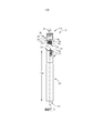
Фиг. 1 представляет собой разобранный вид сбоку фрезерной головки и хвостовика в соответствии с настоящим изобретением;FIG. 1 is an exploded side view of a milling head and shank in accordance with the present invention;
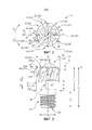
Фиг. 2 представляет собой вид с переднего торца фрезерной головки, показанной на Фиг. 1;FIG. 2 is a front end view of the milling head shown in FIG. 1;
Фиг. 3 представляет собой увеличенный вид сбоку фрезерной головки, показанной на Фиг. 1;FIG. 3 is an enlarged side view of the milling head shown in FIG. 1;
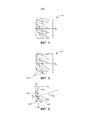
Фиг. 4 представляет собой вид сбоку части режущего участка фрезерной головки, показанной на Фиг. 1-3;FIG. 4 is a side view of a portion of the cutting portion of the milling head shown in FIG. 1-3;
Фиг. 5 представляет собой вид сбоку той же части режущего участка, показанного на Фиг. 3, повернутого в соответствии с ориентацией, показанной на Фиг. 1 и 3; иFIG. 5 is a side view of the same portion of the cutting portion shown in FIG. 3 rotated in accordance with the orientation shown in FIG. 1 and 3; and
Фиг. 6 представляет собой вид сбоку самого нижнего зуба, показанного на Фиг. 5.FIG. 6 is a side view of the lowest tooth shown in FIG. five.
ПОДРОБНОЕ ОПИСАНИЕ ИЗОБРЕТЕНИЯDETAILED DESCRIPTION OF THE INVENTION
[0027] Со ссылкой на Фиг. 1 будут описаны типичные признаки торцевого фрезерного узла 10 типа, к которому относится настоящее изобретение. Торцевой фрезерный узел 10 содержит хвостовик 12 и головку 14.[0027] With reference to FIG. 1, typical features of an
[0028] Хвостовик 12 содержит задний торец 16 хвостовика, передний торец 18 хвостовика и периферийную поверхность 20 хвостовика.[0028] The
[0029] Передний торец 18 хвостовика может быть выполнен с отверстием 22. Отверстие 22 может быть расположено по центру. Отверстие 22 может быть обеспечено внутренней резьбой 24.[0029] The
[0030] Передний торец 18 хвостовика дополнительно может содержать обращенную вперед кольцевую поверхность 26 хвостовика. Кольцевая поверхность 26 хвостовика может окружать отверстие 22.[0030] The
[0031] Хвостовик может иметь ось AS хвостовика, вдоль которой может быть измерена длина LSH хвостовика. Длина LSH хвостовика может быть обеспечена как стандартная длина для удержания в цанговом патроне (не показан).[0031] The shank may have a shank axis AS along which the shank length LSH can be measured. The shank length LSH can be provided as a standard length for holding in a collet chuck (not shown).
[0032] Головка 14 может содержать задний торец 28 головки, передний торец 30 головки и периферийную поверхность 32 головки, продолжающуюся от заднего торца 28 головки до переднего торца 30 головки.[0032] The
[0033] Головка 14 дополнительно содержит участок 34 для соединения с хвостовиком и режущий участок 36.[0033] The
[0034] Участок 34 для соединения с хвостовиком может продолжаться от заднего торца 28 до пересечения 38 участка 34 для соединения с хвостовиком и режущего участка 36.[0034] The
[0035] Участок 34 для соединения с хвостовиком может быть обеспечен наружной резьбой 40. В частности, участок 34 для соединения с хвостовиком может содержать нижний соединительный участок 42 и верхний соединительный участок 44. Верхний соединительный участок 44 может соединять нижний соединительный участок 42 и режущий участок 36. Наружная резьба 40 может быть обеспечена на нижнем соединительном участке 42. Верхний соединительный участок 44 предпочтительно может иметь форму усеченного конуса.[0035] The
[0036] Режущий участок 36 может содержать кольцевую поверхность 46 режущего участка, окружающую участок 34 для соединения с хвостовиком. В частности, кольцевая поверхность 46 режущего участка окружает участок 34 для соединения с хвостовиком на пересечении 38.[0036] The cutting
[0037] Головка 14 может быть закреплена на хвостовике 12 с помощью внутренней и наружной резьб 24, 40, причем кольцевая поверхность 26 хвостовика прилегает к кольцевой поверхности 46 режущего участка.[0037] The
[0038] Далее со ссылкой на Фиг. 2 и 3 будут описаны признаки, конкретно относящиеся к настоящему изобретению.[0038] Next, referring to FIG. 2 and 3, features specific to the present invention will be described.
[0039] Через центр головки 14 в продольном направлении проходит центральная ось AR вращения, определяющая противоположные направления DF, DR вперед и назад по оси и противоположные вращательные предшествующее и последующее направления DP, DS, причем предшествующее направление DP представляет собой направление резания. Примерное направление DI внутрь показано для понимания, но следует понимать, что выражение «направление внутрь» в общем означает направление к центральной оси AR вращения. Подобным образом также показано направление DO наружу, которое следует в общем понимать как направление от центральной оси AR вращения. В дальнейшем используются комбинированные направления, например, «направление вперед и внутрь» и «направление назад и внутрь», которые определяют одно направление, полученное на основе комбинации составляющих обоих указанных направлений, хотя это необязательно точная биссектриса между двумя указанными направлениями.[0039] Through the center of the
[0040] Перпендикулярная плоскость PP расположена на переднем торце 30 головки (т.е. проходит на пересечении ее передней точки, которая в этом случае образована внутренними углами 60, первый передний угол обозначен ссылочной позицией 60A для дальнейшего объяснения) и проходит перпендикулярно центральной оси AR вращения.[0040] The perpendicular plane PP is located at the front end face 30 of the head (i.e., passes at the intersection of its front point, which in this case is formed by the
[0041] Длина LC режущего участка может быть измерена параллельно центральной оси AR вращения. В частности, длина LC режущего участка может быть определена как продолжающаяся от пересечения 38 до переднего торца 30 головки (или, другими словами, до перпендикулярной плоскости PP).[0041] The length LC of the cutting portion can be measured parallel to the central axis of rotation AR. In particular, the length LC of the cutting portion can be defined as extending from the
[0042] Длина LS участка для соединения с хвостовиком может быть измерена параллельно центральной оси AR вращения. В частности, длина LS участка для соединения с хвостовиком может быть определена как продолжающаяся от заднего торца 28 до пересечения 38.[0042] The length LS of the shank connection portion can be measured parallel to the central axis of rotation AR. In particular, the length LS of the shank connection portion can be defined as extending from the
[0043] Диаметр DSC участка для соединения с хвостовиком (т.е. максимальный диаметр участка для соединения с хвостовиком) может быть меньше, чем диаметр DE режущего участка, измеряемый перпендикулярно центральной оси AR вращения. Предпочтительно диаметр DSC участка для соединения с хвостовиком может быть меньше, чем наименьший наружный диаметр DM режущего участка 36.[0043] The diameter DSC of the shank connection portion (ie, the maximum diameter of the shank connection portion) may be smaller than the diameter DE of the cutting portion, measured perpendicular to the central axis of rotation AR. Preferably, the diameter DSC of the shank connection portion may be less than the smallest outer diameter DM of the cutting
[0044] Общая длина LT может быть определена от заднего торца 28 головки до перпендикулярной плоскости PP.[0044] The total length LT can be determined from the
[0045] Режущий участок 36 содержит множество выполненных за одно целое зубьев 50 (например, первый, второй, третий, четвертый, пятый и шестой зубья 50A, 50B, 50C, 50D, 50E, 50F) и множество стружечных канавок 52 (например, первую, вторую, третью, четвертую, пятую и шестую стружечные канавки 52A, 52B, 52C, 52D, 52E, 52F), чередующихся с множеством зубьев 50.[0045] Cutting
[0046] Также обратимся к Фиг. 4-6, зубья 50 и стружечные канавки 52 могут быть идентичными, как показано, поэтому нижеприведенное описание, относящееся к любому зубу или стружечной канавке, следует рассматривать как относящееся ко всем.[0046] Also referring to FIG. 4-6, teeth 50 and chip grooves 52 may be identical as shown, so the following description regarding any tooth or chip groove should be considered to apply to all.
[0047] Первый зуб 50A может содержать заднюю кромку 54A, выпуклый криволинейный внешний угол 56A, главную режущую кромку 58A, выпуклый криволинейный внутренний угол 60A и скошенную режущую кромку 62A.[0047] The
[0048] Задняя кромка 54A может продолжаться вдоль периферийной поверхности 32. Задняя кромка 54A может продолжаться в направлении DR, DI назад и внутрь от внешнего угла 56A.[0048] The trailing
[0049] Внешний угол 56A может быть соединен с задней кромкой 54A и содержит радиальную крайнюю точку 57A (Фиг. 3) режущего участка 36. Радиус ROC внешнего угла может иметь предпочтительное, но примерное значение 0,6 мм.[0049] Outside
[0050] Главная режущая кромка 58A может быть соединена с внешним углом 56A и может продолжаться в направлении DF, DI вперед и внутрь от внешнего угла 56A. В случае, когда режущая кромка 58A является криволинейной в измеримой степени, предпочтительное, но примерное значение радиуса RCE режущей кромки может составлять 10 мм.[0050] The
[0051] Внутренний угол 60A может быть соединен с главной режущей кромкой 58A.[0051] An
[0052] Скошенная режущая кромка 62A может быть соединена с внутренним углом 60A и может продолжаться в направлении DF, DI назад и внутрь от внутреннего угла 60A.[0052] The
[0053] В частности, первая точка 64A соединения (Фиг. 3) может быть образована в месте соединения главной режущей кромки 58A и внутреннего угла 60A, вторая точка 64B соединения может быть образована в месте соединения главной режущей кромки 58A и внешнего угла 56A.[0053] Specifically, the first
[0054] Мнимая прямая линия LI может быть проведена между первой и второй точками 64A, 64B соединения и вместе с перпендикулярной плоскостью PP может образовывать угол α резания. В данном примере радиус RCE режущей кромки является настолько большим, что главная режущая кромка 58A по существу перекрывается с мнимой прямой линией LI.[0054] An imaginary straight line LI may be drawn between the first and second connection points 64A, 64B, and together with the perpendicular plane PP may form a cutting angle α. In this example, the cutting edge radius RCE is so large that the
[0055] Эффективная длина LE резания может быть определена от второй точки 64B соединения до перпендикулярной плоскости PP.[0055] The effective cutting length LE may be determined from the second
[0056] Каждый зуб 50 может быть расположен перед центром, как показано. Со ссылкой на Фиг. 2 головка 14 может поворачиваться до тех пор, пока радиальная линия LR не пересечет точку PI пересечения главной режущей кромки 58A, как показано в этом случае для первого зуба 50A. Точка PI пересечения совпадает с началом предполагаемой главной режущей кромки, т.е. со второй точкой 64B соединения. Следует отметить, что в точках вдоль главной режущей кромки 58A, расположенных ближе к центральной оси AR вращения, чем точка PI пересечения, главная режущая кромка 58A находится перед радиальной линией LR в предшествующем направлении DP (т.е. в направлении резания). Соответственно, при контакте стружки (не показана) с главной режущей кромкой 58A она выбрасывается из головки 14, причем основное направление схематически показано стрелкой, обозначенной ссылочной позицией 66 (которая в большей мере направлена в направлении DO наружу, чем в направлении DI внутрь).[0056] Each tooth 50 can be positioned in front of the center as shown. With reference to FIG. 2, the
[0057] На Фиг. 6 показан угол ϴ захода.[0057] FIG. 6 shows the angle ϴ of approach.
[0058] На переднем торце 30 может быть обеспечено охлаждающее отверстие 68.[0058] A
[0059] Используем первую стружечную канавку 52A в качестве примера, во время выполнения торцевого фрезерования охлаждающая среда, выходящая из охлаждающего отверстия 68 (не показано), течет через смежные зубья (например, в направлении, показанном стрелкой 69), что может дополнительно содействовать выбрасыванию стружки (не показана), уже продвинутой в направлении, показанном стрелкой 66.[0059] Using the first chip groove 52A as an example, during face milling, coolant exiting the cooling hole 68 (not shown) flows through adjacent teeth (eg, in the direction of arrow 69), which can further aid ejection chips (not shown) already advanced in the direction of arrow 66.
[0060] На Фиг. 4 показан угол H наклона винтовой линии. Хотя значения угла наклона винтовой линии для головки этого типа не ограничены, предпочтительный диапазон будет удовлетворять условию 10°≤H≤30°. Значения, близкие к 20°, считаются более предпочтительными.[0060] FIG. 4 shows the angle H of the helix. Although the helix angle values for this type of head are not limited, the preferable range will satisfy the
[0061] Вернемся к Фиг. 3, следует отметить, что головка 14 обеспечена крепежной конструкцией 70 вдоль периферийной поверхности 32. Примерная крепежная конструкция 70 содержит две идентичные плоские выемки 72 на противоположных сторонах головки 14 (только одна из которых показана), которые выполнены с возможностью зацепления с гаечным ключом (не показан).[0061] Returning to FIG. 3, it should be noted that the
[0062] Поскольку крепежная конструкция 70 вдоль периферийной поверхности 32 головки может занимать некоторую часть длины режущего участка (т.е. для показанной крепежной конструкции 70 требуется длина LF крепежной конструкции), головка 14 может быть удлинена до большей длины LC режущего участка, чем, строго говоря, необходимо для целей теплопередачи или обработки (т.е. такое удлинение вместо этого будет облегчать установку головки 14 на хвостовик 12).[0062] Since the
[0063] В показанном примере длина LC режущего участка и диаметр DE режущего участка равны и, следовательно, LDR=1,00.[0063] In the example shown, the length LC of the cutting portion and the diameter DE of the cutting portion are equal, and therefore LDR = 1.00.
Claims (30)
Applications Claiming Priority (3)
| Application Number | Priority Date | Filing Date | Title |
|---|---|---|---|
| US15/096,806 US10335871B2 (en) | 2016-04-12 | 2016-04-12 | Replaceable face-milling head with integrally formed threaded shank-connector |
| US15/096,806 | 2016-04-12 | ||
| PCT/IL2017/050379 WO2017179037A1 (en) | 2016-04-12 | 2017-03-27 | Replaceable face-milling head with integrally formed threaded shank-connector |
Publications (3)
| Publication Number | Publication Date |
|---|---|
| RU2018139518A RU2018139518A (en) | 2020-05-12 |
| RU2018139518A3 RU2018139518A3 (en) | 2020-06-03 |
| RU2727632C2 true RU2727632C2 (en) | 2020-07-22 |
Family
ID=58640946
Family Applications (1)
| Application Number | Title | Priority Date | Filing Date |
|---|---|---|---|
| RU2018139518A RU2727632C2 (en) | 2016-04-12 | 2017-03-27 | Replaceable end milling head with an integral threaded section for connection with shank |
Country Status (14)
| Country | Link |
|---|---|
| US (1) | US10335871B2 (en) |
| EP (1) | EP3442735B1 (en) |
| JP (1) | JP6993344B2 (en) |
| KR (1) | KR102349807B1 (en) |
| CN (1) | CN108883479B (en) |
| BR (1) | BR112018069775B1 (en) |
| CA (1) | CA3019174C (en) |
| ES (1) | ES2959831T3 (en) |
| IL (1) | IL261931B (en) |
| PL (1) | PL3442735T3 (en) |
| PT (1) | PT3442735T (en) |
| RU (1) | RU2727632C2 (en) |
| TW (1) | TWI729113B (en) |
| WO (1) | WO2017179037A1 (en) |
Families Citing this family (12)
| Publication number | Priority date | Publication date | Assignee | Title |
|---|---|---|---|---|
| WO2013175478A2 (en) | 2012-05-24 | 2013-11-28 | Gershon System Ltd. | Method for designing a cutting edge of a cutting tool, cutting tools comprising the same, and cutting elements with multiple such cutting portions |
| JP6056611B2 (en) * | 2013-03-29 | 2017-01-11 | 三菱マテリアル株式会社 | Replaceable cutting head |
| US9975183B2 (en) * | 2013-09-17 | 2018-05-22 | Gershon System Ltd. | Cutting element and a method of cutting using the same |
| EP3042729B1 (en) * | 2015-01-12 | 2021-03-10 | Sandvik Intellectual Property AB | Ceramic milling cutter |
| DE102015214434A1 (en) * | 2015-07-29 | 2017-02-02 | Franz Haimer Maschinenbau Kg | Rotatable cutting tool and key for this |
| KR20210034663A (en) | 2018-09-25 | 2021-03-30 | 콘프로페 테크놀로지 그룹 컴퍼니 리미티드 | Diamond cutting tool for hard brittle materials |
| US11420272B2 (en) * | 2019-01-08 | 2022-08-23 | Iscar, Ltd. | Milling head having integrally formed cutting edges and rotary milling tool |
| DE102019114704A1 (en) * | 2019-05-31 | 2020-12-03 | Hofmann & Vratny Ohg | Milling tool with internal cooling |
| US11446746B2 (en) | 2019-12-10 | 2022-09-20 | Iscar, Ltd. | Replaceable cutting head having back-tapered conical external thread and rotary cutting tool |
| CN110899808A (en) * | 2019-12-18 | 2020-03-24 | 株洲钻石切削刀具股份有限公司 | Cutting tool |
| US11376676B2 (en) | 2020-07-07 | 2022-07-05 | Iscar, Ltd. | Rotary cutting head having cutting edges extending past key actuating portion |
| US11426803B2 (en) * | 2020-09-08 | 2022-08-30 | Iscar, Ltd. | Replaceable cutting head having external thread with concavely curved root and rotary cutting tool |
Citations (5)
| Publication number | Priority date | Publication date | Assignee | Title |
|---|---|---|---|---|
| RU53199U1 (en) * | 2005-06-29 | 2006-05-10 | Общество с ограниченной ответственностью "Техноинструмент" | END CHANGE MILL |
| RU2372172C2 (en) * | 2004-05-24 | 2009-11-10 | Искар Лтд. | Drill with break-out cutting head |
| RU111472U1 (en) * | 2011-05-06 | 2011-12-20 | Государственное образовательное учреждение высшего профессионального образования "Алтайский государственный технический университет им. И.И. Ползунова" (АлтГТУ) | UNIT FOR FASTENING REPLACEMENT MODULES OF BLOCK INSTRUMENTAL EQUIPMENT |
| GB2487303A (en) * | 2011-01-17 | 2012-07-18 | Kennametal Inc | Monolithic end mill suitable to be made of ceramic material |
| WO2015058881A1 (en) * | 2013-10-21 | 2015-04-30 | Walter Ag | End milling cutter for heat-resistant superalloys |
Family Cites Families (38)
| Publication number | Priority date | Publication date | Assignee | Title |
|---|---|---|---|---|
| US756339A (en) * | 1903-11-14 | 1904-04-05 | William R Down | Composite drill. |
| US4438953A (en) * | 1981-02-27 | 1984-03-27 | Hughes Tool Company | Tool joint bench mark |
| US5094573A (en) * | 1988-07-21 | 1992-03-10 | Hougen Everett D | Multidirectional cutting tool |
| IL106697A (en) * | 1993-08-15 | 1996-10-16 | Iscar Ltd | Cutting insert with integral clamping means |
| SE509218C2 (en) * | 1994-08-29 | 1998-12-21 | Sandvik Ab | shaft Tools |
| US6056485A (en) * | 1998-09-01 | 2000-05-02 | Kennametal Inc. | Ramp plunge and feed milling cutter |
| IL136032A (en) * | 2000-05-09 | 2003-12-10 | Iscar Ltd | Tool joint |
| IL137316A (en) | 2000-07-16 | 2004-01-04 | Iscar Ltd | Cutting tool assembly |
| SE527703C2 (en) * | 2004-08-19 | 2006-05-16 | Sandvik Intellectual Property | Rotatable tool and cutting head with axially serrated engaging means |
| SE528299C2 (en) * | 2004-09-24 | 2006-10-17 | Seco Tools Ab | Cutting tip and cutting tool with holder part designed as truncated conical thread |
| SE528251C2 (en) * | 2004-09-24 | 2006-10-03 | Seco Tools Ab | Trade for tools and tools with a transition part between a threaded part and a supporting part |
| SE530043C2 (en) | 2006-04-20 | 2008-02-12 | Sandvik Intellectual Property | Tools for chip separating machining and part thereof |
| SE532394C2 (en) * | 2007-06-04 | 2010-01-12 | Sandvik Intellectual Property | Tools for chip separating machining and basic body for this |
| FR2920327B1 (en) * | 2007-08-30 | 2009-11-20 | Snecma | GRAZING MILL FOR MACHINING WITH HIGH ADVANCE AND LOW PASS DEPTH |
| IL191330A (en) * | 2008-05-11 | 2014-11-30 | Kennametal Inc | Milling tool assembly having a replaceable cutter |
| US9227253B1 (en) * | 2009-03-30 | 2016-01-05 | Steven M. Swift | Rotary cutter for machining materials |
| CN201439135U (en) * | 2009-06-03 | 2010-04-21 | 铠钜科技股份有限公司 | Composite material tool bit of replaceable milling tool |
| DE102009034202B3 (en) | 2009-07-16 | 2010-09-23 | Hartmetall-Werkzeugfabrik Paul Horn Gmbh | Two-part tool for machining with threaded coupling |
| JP5350149B2 (en) * | 2009-09-07 | 2013-11-27 | ダイジ▲ェ▼ット工業株式会社 | Cutting tools |
| DE102010004526B4 (en) * | 2010-01-14 | 2014-05-22 | Kennametal Inc. | cutting tool |
| US9827620B2 (en) * | 2010-09-29 | 2017-11-28 | Mitsubishi Materials Corporation | Head replacement-type cutting tool |
| DE102011012140B4 (en) | 2011-02-24 | 2020-07-09 | Kennametal Inc. | Milling cutters, in particular ball end mills |
| ITFI20110153A1 (en) * | 2011-07-25 | 2013-01-26 | Nuovo Pignone Spa | "CUTTING TOOL" |
| JP5664506B2 (en) * | 2011-09-09 | 2015-02-04 | 三菱マテリアル株式会社 | Replaceable head cutting tool |
| KR101559263B1 (en) * | 2011-10-17 | 2015-10-08 | 미츠비시 마테리알 가부시키가이샤 | Holder for head replacement-type cutting tool, and head replacement-type cutting tool |
| DE102012100976B4 (en) * | 2012-02-07 | 2014-04-24 | Franz Haimer Maschinenbau Kg | Screwing tool and tool holder for such a screw-in |
| US9802256B2 (en) * | 2012-02-07 | 2017-10-31 | Franz Haimer Maschinenbau Kg | Screw-in tool and tool holder for such a screw-in tool |
| EP2832481A4 (en) * | 2012-03-29 | 2015-08-12 | Hitachi Tool Eng | Machining head, holder and exchangeable tip cutting tool |
| US8662800B2 (en) * | 2012-04-11 | 2014-03-04 | Sandvik Intellectual Property Ab | Cutting head with coolant channel |
| DE102012107546A1 (en) | 2012-08-17 | 2014-02-20 | Franz Haimer Maschinenbau Kg | tooling |
| US20140056658A1 (en) * | 2012-08-24 | 2014-02-27 | Sumitomo Electric Hardmetal Corp. | Cutting tool with removable head |
| DE102013100939A1 (en) * | 2013-01-30 | 2014-07-31 | Franz Haimer Maschinenbau Kg | Tool holder for a screw-in tool |
| US20140356081A1 (en) * | 2013-05-30 | 2014-12-04 | Kennametal Inc. | End mill with high ramp angle capability |
| CN203484723U (en) * | 2013-10-11 | 2014-03-19 | 中航飞机股份有限公司西安飞机分公司 | Combined numerical control milling cutter |
| US9381583B2 (en) * | 2014-02-12 | 2016-07-05 | Kennametal Inc. | Prismatic and cylindrical cutting inserts |
| US20150258616A1 (en) * | 2014-03-11 | 2015-09-17 | Frank J Stanbach | End mill |
| US9889509B2 (en) * | 2014-05-05 | 2018-02-13 | Kennametal Inc. | Cutter heads with improved coupling |
| US10105771B2 (en) * | 2016-03-21 | 2018-10-23 | Iscar, Ltd. | Rotary cutting tool having tool holder with conical internal thread and replaceable cutting head with straight external thread, and said tool holder |
-
2016
- 2016-04-12 US US15/096,806 patent/US10335871B2/en active Active
-
2017
- 2017-03-27 CA CA3019174A patent/CA3019174C/en active Active
- 2017-03-27 EP EP17720236.3A patent/EP3442735B1/en active Active
- 2017-03-27 BR BR112018069775-3A patent/BR112018069775B1/en active IP Right Grant
- 2017-03-27 RU RU2018139518A patent/RU2727632C2/en active
- 2017-03-27 JP JP2018545190A patent/JP6993344B2/en active Active
- 2017-03-27 CN CN201780023279.7A patent/CN108883479B/en active Active
- 2017-03-27 WO PCT/IL2017/050379 patent/WO2017179037A1/en active Application Filing
- 2017-03-27 KR KR1020187029307A patent/KR102349807B1/en active IP Right Grant
- 2017-03-27 PT PT177202363T patent/PT3442735T/en unknown
- 2017-03-27 PL PL17720236.3T patent/PL3442735T3/en unknown
- 2017-03-27 ES ES17720236T patent/ES2959831T3/en active Active
- 2017-04-10 TW TW106111895A patent/TWI729113B/en active
-
2018
- 2018-09-25 IL IL261931A patent/IL261931B/en unknown
Patent Citations (5)
| Publication number | Priority date | Publication date | Assignee | Title |
|---|---|---|---|---|
| RU2372172C2 (en) * | 2004-05-24 | 2009-11-10 | Искар Лтд. | Drill with break-out cutting head |
| RU53199U1 (en) * | 2005-06-29 | 2006-05-10 | Общество с ограниченной ответственностью "Техноинструмент" | END CHANGE MILL |
| GB2487303A (en) * | 2011-01-17 | 2012-07-18 | Kennametal Inc | Monolithic end mill suitable to be made of ceramic material |
| RU111472U1 (en) * | 2011-05-06 | 2011-12-20 | Государственное образовательное учреждение высшего профессионального образования "Алтайский государственный технический университет им. И.И. Ползунова" (АлтГТУ) | UNIT FOR FASTENING REPLACEMENT MODULES OF BLOCK INSTRUMENTAL EQUIPMENT |
| WO2015058881A1 (en) * | 2013-10-21 | 2015-04-30 | Walter Ag | End milling cutter for heat-resistant superalloys |
Also Published As
| Publication number | Publication date |
|---|---|
| US10335871B2 (en) | 2019-07-02 |
| KR102349807B1 (en) | 2022-01-12 |
| US20170291230A1 (en) | 2017-10-12 |
| BR112018069775B1 (en) | 2022-07-12 |
| IL261931A (en) | 2018-10-31 |
| ES2959831T3 (en) | 2024-02-28 |
| IL261931B (en) | 2021-12-01 |
| CA3019174C (en) | 2024-01-02 |
| JP2019515801A (en) | 2019-06-13 |
| WO2017179037A1 (en) | 2017-10-19 |
| PT3442735T (en) | 2023-10-16 |
| JP6993344B2 (en) | 2022-01-13 |
| CA3019174A1 (en) | 2017-10-19 |
| RU2018139518A (en) | 2020-05-12 |
| CN108883479B (en) | 2020-07-10 |
| KR20180126509A (en) | 2018-11-27 |
| EP3442735B1 (en) | 2023-09-20 |
| TWI729113B (en) | 2021-06-01 |
| RU2018139518A3 (en) | 2020-06-03 |
| CN108883479A (en) | 2018-11-23 |
| PL3442735T3 (en) | 2024-03-04 |
| EP3442735A1 (en) | 2019-02-20 |
| TW201739548A (en) | 2017-11-16 |
| BR112018069775A2 (en) | 2019-02-05 |
Similar Documents
| Publication | Publication Date | Title |
|---|---|---|
| RU2727632C2 (en) | Replaceable end milling head with an integral threaded section for connection with shank | |
| EP2650069B1 (en) | Cutting head with coolant channel and method of forming such a cutting head | |
| CA2763051C (en) | Drilling tool | |
| CN108290224B (en) | Turning insert | |
| WO2015199031A1 (en) | Cutting insert, cutting tool, and method for manufacturing cut product | |
| US20160175948A1 (en) | Multi-flute ball end mill | |
| US9492877B2 (en) | Drill | |
| JP2018534159A (en) | Turning insert and method | |
| JP2011500350A (en) | Cutting tool | |
| US6976815B2 (en) | Milling cutter having three continuously curved cutting edges | |
| TW202014261A (en) | Cutting head having tip portion with radially extending front cutting edges provided with both negative and positive rake angles, and rotary cutting tool | |
| US20160271706A1 (en) | Endmill with convex ramping edge | |
| JP2017080864A (en) | Cutting edge exchange-type reamer and reamer insert | |
| CN110560768A (en) | Cutting tool and tool bit structure thereof | |
| CN210648707U (en) | Cutting tool and tool bit structure thereof | |
| US10792738B2 (en) | Cutting tool and method of manufacturing machined product | |
| CN109996634B (en) | Ball end mill blade, ball end mill cutter body and ball end mill | |
| EP3342515B1 (en) | A twist drill and an exchangeable head for a twist drill | |
| US11951553B2 (en) | Rotatable cutting head having tip portion with three radially extending cutting edges forming a rectilinear rotational profile | |
| CN212443409U (en) | Tungsten steel milling cutter for aluminum | |
| CN209886751U (en) | Drilling and front chamfering compound tool | |
| CN110102799A (en) | A kind of quick change, which dies, considers drill bit to be worth doing |