RU2727083C2 - Food preparation system with flushing elements and strut - Google Patents
Food preparation system with flushing elements and strut Download PDFInfo
- Publication number
- RU2727083C2 RU2727083C2 RU2018136365A RU2018136365A RU2727083C2 RU 2727083 C2 RU2727083 C2 RU 2727083C2 RU 2018136365 A RU2018136365 A RU 2018136365A RU 2018136365 A RU2018136365 A RU 2018136365A RU 2727083 C2 RU2727083 C2 RU 2727083C2
- Authority
- RU
- Russia
- Prior art keywords
- spray
- cooking
- spray nozzles
- bottom wall
- cooking chamber
- Prior art date
Links
- 238000011010 flushing procedure Methods 0.000 title claims abstract description 49
- 235000013305 food Nutrition 0.000 title abstract description 33
- 238000002360 preparation method Methods 0.000 title abstract description 8
- 238000010411 cooking Methods 0.000 claims abstract description 235
- 238000005485 electric heating Methods 0.000 claims abstract description 58
- 125000006850 spacer group Chemical group 0.000 claims abstract description 44
- 238000000034 method Methods 0.000 claims abstract description 18
- 238000004140 cleaning Methods 0.000 claims abstract description 13
- 238000005507 spraying Methods 0.000 claims abstract description 8
- 230000000694 effects Effects 0.000 claims abstract description 3
- 239000007921 spray Substances 0.000 claims description 149
- 238000010438 heat treatment Methods 0.000 claims description 27
- 238000001914 filtration Methods 0.000 claims description 16
- 239000012530 fluid Substances 0.000 claims description 10
- 238000004891 communication Methods 0.000 claims description 9
- 239000000945 filler Substances 0.000 claims description 9
- 238000009835 boiling Methods 0.000 abstract 3
- 239000000126 substance Substances 0.000 abstract 1
- 239000002245 particle Substances 0.000 description 24
- 239000003925 fat Substances 0.000 description 8
- 235000019197 fats Nutrition 0.000 description 8
- 239000003921 oil Substances 0.000 description 7
- 238000012423 maintenance Methods 0.000 description 4
- 238000005406 washing Methods 0.000 description 4
- 230000002411 adverse Effects 0.000 description 3
- 239000002699 waste material Substances 0.000 description 3
- 230000008859 change Effects 0.000 description 2
- 238000006243 chemical reaction Methods 0.000 description 2
- 230000008569 process Effects 0.000 description 2
- 238000012546 transfer Methods 0.000 description 2
- 241000251468 Actinopterygii Species 0.000 description 1
- 229910001209 Low-carbon steel Inorganic materials 0.000 description 1
- 241001465754 Metazoa Species 0.000 description 1
- 235000002595 Solanum tuberosum Nutrition 0.000 description 1
- 244000061456 Solanum tuberosum Species 0.000 description 1
- 238000009825 accumulation Methods 0.000 description 1
- 230000002378 acidificating effect Effects 0.000 description 1
- 238000005452 bending Methods 0.000 description 1
- 230000009286 beneficial effect Effects 0.000 description 1
- 230000001680 brushing effect Effects 0.000 description 1
- 238000002144 chemical decomposition reaction Methods 0.000 description 1
- 150000001875 compounds Chemical class 0.000 description 1
- 238000011109 contamination Methods 0.000 description 1
- 239000008162 cooking oil Substances 0.000 description 1
- 230000008878 coupling Effects 0.000 description 1
- 238000010168 coupling process Methods 0.000 description 1
- 238000005859 coupling reaction Methods 0.000 description 1
- 230000003247 decreasing effect Effects 0.000 description 1
- 238000013461 design Methods 0.000 description 1
- 239000003599 detergent Substances 0.000 description 1
- 230000006866 deterioration Effects 0.000 description 1
- 239000000428 dust Substances 0.000 description 1
- 230000005611 electricity Effects 0.000 description 1
- 239000000796 flavoring agent Substances 0.000 description 1
- 235000019634 flavors Nutrition 0.000 description 1
- 239000003292 glue Substances 0.000 description 1
- 239000012535 impurity Substances 0.000 description 1
- 238000009434 installation Methods 0.000 description 1
- 230000002452 interceptive effect Effects 0.000 description 1
- 239000000463 material Substances 0.000 description 1
- 238000012986 modification Methods 0.000 description 1
- 230000004048 modification Effects 0.000 description 1
- 230000003647 oxidation Effects 0.000 description 1
- 238000007254 oxidation reaction Methods 0.000 description 1
- 230000000737 periodic effect Effects 0.000 description 1
- 235000012015 potatoes Nutrition 0.000 description 1
- 244000144977 poultry Species 0.000 description 1
- 230000004044 response Effects 0.000 description 1
- 239000013049 sediment Substances 0.000 description 1
- 235000002316 solid fats Nutrition 0.000 description 1
- 229910001220 stainless steel Inorganic materials 0.000 description 1
- 239000010935 stainless steel Substances 0.000 description 1
- 238000012360 testing method Methods 0.000 description 1
- 235000019871 vegetable fat Nutrition 0.000 description 1
- XLYOFNOQVPJJNP-UHFFFAOYSA-N water Substances O XLYOFNOQVPJJNP-UHFFFAOYSA-N 0.000 description 1
- 238000003466 welding Methods 0.000 description 1
- 238000009736 wetting Methods 0.000 description 1
Images


Classifications
-
- A—HUMAN NECESSITIES
- A23—FOODS OR FOODSTUFFS; TREATMENT THEREOF, NOT COVERED BY OTHER CLASSES
- A23L—FOODS, FOODSTUFFS, OR NON-ALCOHOLIC BEVERAGES, NOT COVERED BY SUBCLASSES A21D OR A23B-A23J; THEIR PREPARATION OR TREATMENT, e.g. COOKING, MODIFICATION OF NUTRITIVE QUALITIES, PHYSICAL TREATMENT; PRESERVATION OF FOODS OR FOODSTUFFS, IN GENERAL
- A23L5/00—Preparation or treatment of foods or foodstuffs, in general; Food or foodstuffs obtained thereby; Materials therefor
- A23L5/10—General methods of cooking foods, e.g. by roasting or frying
- A23L5/11—General methods of cooking foods, e.g. by roasting or frying using oil
-
- A—HUMAN NECESSITIES
- A47—FURNITURE; DOMESTIC ARTICLES OR APPLIANCES; COFFEE MILLS; SPICE MILLS; SUCTION CLEANERS IN GENERAL
- A47J—KITCHEN EQUIPMENT; COFFEE MILLS; SPICE MILLS; APPARATUS FOR MAKING BEVERAGES
- A47J37/00—Baking; Roasting; Grilling; Frying
- A47J37/12—Deep fat fryers, e.g. for frying fish or chips
- A47J37/1266—Control devices, e.g. to control temperature, level or quality of the frying liquid
-
- A—HUMAN NECESSITIES
- A47—FURNITURE; DOMESTIC ARTICLES OR APPLIANCES; COFFEE MILLS; SPICE MILLS; SUCTION CLEANERS IN GENERAL
- A47J—KITCHEN EQUIPMENT; COFFEE MILLS; SPICE MILLS; APPARATUS FOR MAKING BEVERAGES
- A47J37/00—Baking; Roasting; Grilling; Frying
- A47J37/12—Deep fat fryers, e.g. for frying fish or chips
- A47J37/1257—Deep fat fryers, e.g. for frying fish or chips electrically heated
- A47J37/1261—Details of the heating elements; Fixation of the heating elements to the frying vessel
-
- A—HUMAN NECESSITIES
- A47—FURNITURE; DOMESTIC ARTICLES OR APPLIANCES; COFFEE MILLS; SPICE MILLS; SUCTION CLEANERS IN GENERAL
- A47J—KITCHEN EQUIPMENT; COFFEE MILLS; SPICE MILLS; APPARATUS FOR MAKING BEVERAGES
- A47J37/00—Baking; Roasting; Grilling; Frying
- A47J37/12—Deep fat fryers, e.g. for frying fish or chips
- A47J37/1223—Deep fat fryers, e.g. for frying fish or chips with means for filtering the frying liquid
-
- A—HUMAN NECESSITIES
- A47—FURNITURE; DOMESTIC ARTICLES OR APPLIANCES; COFFEE MILLS; SPICE MILLS; SUCTION CLEANERS IN GENERAL
- A47J—KITCHEN EQUIPMENT; COFFEE MILLS; SPICE MILLS; APPARATUS FOR MAKING BEVERAGES
- A47J37/00—Baking; Roasting; Grilling; Frying
- A47J37/12—Deep fat fryers, e.g. for frying fish or chips
- A47J37/1233—Deep fat fryers, e.g. for frying fish or chips the frying liquid being heated outside the frying vessel, e.g. by pumping it through a heat exchanger
- A47J37/1238—Deep fat fryers, e.g. for frying fish or chips the frying liquid being heated outside the frying vessel, e.g. by pumping it through a heat exchanger and the oil being returned to the frying vessel by means of a spraying system
-
- A—HUMAN NECESSITIES
- A47—FURNITURE; DOMESTIC ARTICLES OR APPLIANCES; COFFEE MILLS; SPICE MILLS; SUCTION CLEANERS IN GENERAL
- A47J—KITCHEN EQUIPMENT; COFFEE MILLS; SPICE MILLS; APPARATUS FOR MAKING BEVERAGES
- A47J37/00—Baking; Roasting; Grilling; Frying
- A47J37/12—Deep fat fryers, e.g. for frying fish or chips
- A47J37/1242—Deep fat fryers, e.g. for frying fish or chips heated with burners
- A47J37/1247—Details of the burners; Details of the channels for guiding the combustion gases
-
- A—HUMAN NECESSITIES
- A47—FURNITURE; DOMESTIC ARTICLES OR APPLIANCES; COFFEE MILLS; SPICE MILLS; SUCTION CLEANERS IN GENERAL
- A47J—KITCHEN EQUIPMENT; COFFEE MILLS; SPICE MILLS; APPARATUS FOR MAKING BEVERAGES
- A47J37/00—Baking; Roasting; Grilling; Frying
- A47J37/12—Deep fat fryers, e.g. for frying fish or chips
- A47J37/1271—Accessories
-
- A—HUMAN NECESSITIES
- A47—FURNITURE; DOMESTIC ARTICLES OR APPLIANCES; COFFEE MILLS; SPICE MILLS; SUCTION CLEANERS IN GENERAL
- A47J—KITCHEN EQUIPMENT; COFFEE MILLS; SPICE MILLS; APPARATUS FOR MAKING BEVERAGES
- A47J37/00—Baking; Roasting; Grilling; Frying
- A47J37/12—Deep fat fryers, e.g. for frying fish or chips
- A47J37/1276—Constructional details
- A47J37/1285—Valves or arrangements to drain used oil or food particles settled at the bottom of the frying vessel
-
- B—PERFORMING OPERATIONS; TRANSPORTING
- B08—CLEANING
- B08B—CLEANING IN GENERAL; PREVENTION OF FOULING IN GENERAL
- B08B9/00—Cleaning hollow articles by methods or apparatus specially adapted thereto
- B08B9/08—Cleaning containers, e.g. tanks
- B08B9/093—Cleaning containers, e.g. tanks by the force of jets or sprays
-
- B—PERFORMING OPERATIONS; TRANSPORTING
- B08—CLEANING
- B08B—CLEANING IN GENERAL; PREVENTION OF FOULING IN GENERAL
- B08B2209/00—Details of machines or methods for cleaning hollow articles
- B08B2209/08—Details of machines or methods for cleaning containers, e.g. tanks
Landscapes
- Engineering & Computer Science (AREA)
- Food Science & Technology (AREA)
- Chemical & Material Sciences (AREA)
- Oil, Petroleum & Natural Gas (AREA)
- Mechanical Engineering (AREA)
- Health & Medical Sciences (AREA)
- Nutrition Science (AREA)
- Life Sciences & Earth Sciences (AREA)
- Polymers & Plastics (AREA)
- Frying-Pans Or Fryers (AREA)
Abstract
Description
Перекрестная ссылка на родственные заявкиCross-reference to related claims
[0001] Настоящая заявка испрашивает приоритет согласно предварительной заявке на патент США № 62/309,650, поданной 17 марта 2016 г., раскрытие которой включено в настоящую заявку посредством ссылки.[0001] This application claims priority under US Provisional Patent Application No. 62 / 309,650, filed March 17, 2016, the disclosure of which is incorporated herein by reference.
Область техники, к которой относится изобретениеThe technical field to which the invention relates
[0002] Настоящее раскрытие в основном относится к фритюрницам, таким как открытые фритюрницы или фритюрницы, работающие под давлением. Более конкретно, настоящее раскрытие относится к устройству и способам использования промывочных элементов и распорок, соединенных с нагревательными элементами в варочных камерах.[0002] The present disclosure generally relates to deep fryers such as open fryers or pressure fryers. More specifically, the present disclosure relates to apparatus and methods for using rinsing elements and spacers connected to heating elements in cooking chambers.
Предпосылки создания изобретенияBackground of the invention
[0003] Жарка на масле в основном используется как способ тепловой обработки широкого диапазона пищевых продуктов, таких как мясо птицы, рыба, картошка и тому подобное. Промышленные фритюрницы включают в себя одну или более варочных камер (также называемых емкостями для жарки), которые заполняют средой для приготовления пищи, такой как масло или твердые жиры. Тепло обычно подается в среду для приготовления пищи с помощью электрического нагревательного элемента, погруженного в среду для приготовления пищи или газовой горелки, термически соединенной со средой для приготовления пищи через стенки варочной камеры. Когда среда для приготовления пищи достигает заданной температуры тепловой обработки, пищевые продукты располагают в среде для приготовления пищи в течение заданного количества времени, в течение которого пищевые продукты готовятся за счет тепла среды для приготовления пищи. Для обеспечения загрузки и удаления пищевых продуктов, пищевые продукты обычно размещают внутри емкости (например, проволочная корзина), и емкость опускают в среду для приготовления пищи в течение заданного количества времени.[0003] Oil frying is mainly used as a method for cooking a wide range of food products such as poultry, fish, potatoes, and the like. Commercial deep fryers include one or more cooking chambers (also called frying pots) that are filled with a cooking medium such as oil or solid fats. Heat is typically supplied to the cooking medium by an electric heating element immersed in the cooking medium or a gas burner thermally coupled to the cooking medium through the walls of the cooking chamber. When the cooking medium reaches a predetermined cooking temperature, the food is positioned in the cooking medium for a predetermined amount of time during which the food is cooked by the heat of the cooking medium. To facilitate loading and disposal of food, food is typically placed inside a container (eg, a wire basket) and the container is lowered into the cooking medium for a predetermined amount of time.
[0004] Среда для приготовления пищи обычно повторно используется для множества циклов тепловой обработки, которые могут включать в себя циклы тепловой обработки для разных пищевых продуктов. Однако, среда для приготовления пищи ухудшается с течением времени. Это ухудшение может быть вызвано загрязнением частицами, выделяемыми готовящимися пищевыми продуктами, и/или вследствие химического разрушения, вызванного теплом, окислением и реакциями с пищевыми продуктами. Кроме того, так как частицы пищевых продуктов накапливаются в среде для приготовления пищи, вкусовые характеристики частиц пищевых продуктов могут влиять на среду для приготовления пищи. Это влияние может отрицательно влиять на качество приготовленных пищевых продуктов. В некоторых случаях такое изменение среды для приготовления пищи не становится очевидным, пока не возникнет значительное изменение. Эти химические реакции и примеси вкуса и аромата могут сокращать срок полезного использования среды для приготовления пищи и могут приводить к более частой замене среды для приготовления пищи. Эти нежелательные частицы могут оставаться во фритюрнице и накапливаться в нижней части и/или на боковых стенках варочной камеры. Как использовано в данном документе, частицы могут включать в себя, например, крупинки, осадок, комочки, шкварки, соединения, портящие текучую среду для приготовления пищи, и тому подобное или их сочетания. Кроме того, частицы могут включать в себя пищевые частицы во взвешенном состоянии, изменяющиеся от частиц пыли до больших частиц шкварок или крупинок пищевых продуктов.[0004] The cooking medium is typically reused for a variety of cooking cycles, which may include cooking cycles for different foods. However, the cooking environment degrades over time. This deterioration can be caused by particle contamination from the food being prepared and / or chemical degradation caused by heat, oxidation and reactions with food. In addition, since food particles accumulate in the cooking environment, the flavor characteristics of the food particles can affect the food preparation environment. This influence can adversely affect the quality of the cooked food. In some cases, such a change in the cooking environment does not become apparent until a significant change occurs. These chemical reactions and impurities of taste and aroma can shorten the useful life of the cooking medium and can lead to more frequent replacement of the cooking medium. These unwanted particles can remain in the deep fat fryer and accumulate in the bottom and / or on the side walls of the cooking chamber. As used herein, particles can include, for example, grains, sediment, lumps, greaves, compounds that spoil the cooking fluid, and the like, or combinations thereof. In addition, the particles can include suspended food particles ranging from dust particles to large greaves or food grains.
[0005] По меньшей мере по этим причинам среду для приготовления пищи можно периодически фильтровать для поддержания качества тепловой обработки и продления рабочего времени действия среды для приготовления пищи. Частая фильтрация может продлевать срок полезной службы среды для приготовления пищи, таким образом, уменьшая затраты на приведение в действие фритюрницы путем уменьшения частоты, с которой необходимо заменять среду для приготовления пищи. Снижения затрат путем фильтрации могут быть особенно очевидными при использовании среды для приготовления пищи, которая содержит уменьшенные количества транс жиров, которые стали популярными, но обычно более дорогими по сравнению с другими типами сред для приготовления пищи. [0005] For at least these reasons, the cooking medium can be periodically filtered to maintain the quality of the cooking and extend the operating time of the cooking medium. Frequent filtration can extend the useful life of the cooking media, thus reducing the cost of operating the fryer by reducing the frequency with which the cooking media must be replaced. The cost savings through filtration can be especially evident when using cooking media that contain reduced amounts of trans fats, which have become popular but generally more expensive compared to other types of cooking media.
[0006] Таким образом, может быть экономически выгодным фильтрация среды для приготовления пищи для увеличения срока полезной службы путем увеличения частоты фильтрации, используя такие среды для приготовления пищи только для выбранных пищевых продуктов и/или уменьшения объема (и размера) варочной камеры, в которой используются такие среды для приготовления пищи. Тем не менее, при возврате этой среды для приготовления пищи в варочную камеру, процесс фильтрации может уменьшать количество среды для приготовления пищи, остающейся в варочной камере. Если количество среды для приготовления пищи опускается ниже заданного уровня, тогда пищевой продукт, который готовится в варочной камере, может быть не полностью приготовлен и/или не одинаково приготовлен, и качество пищевого продукта, приготовленного во фритюрнице, может ухудшиться.[0006] Thus, it may be economical to filter the cooking media to increase useful life by increasing the filtration frequency, using such cooking media only for selected foods and / or reducing the volume (and size) of the cooking chamber in which such cooking media are used. However, by returning this cooking medium to the cooking chamber, the filtration process can reduce the amount of cooking medium remaining in the cooking chamber. If the amount of the cooking medium falls below a predetermined level, then the food that is being cooked in the cooking chamber may not be completely cooked and / or not uniformly cooked, and the quality of the food prepared in the deep fryer may deteriorate.
[0007] По существу, существует необходимость в очистке варочных камер фритюрнице быстрым и эффективным способом за счет удаления накопления частиц в варочных камерах, которые отрицательно влияют на качество пищевого продукта, приготовленного с помощью среды для приготовления пищи в варочных камерах. Удаление накопления частиц может быть выгодным в труднодоступных областях (например, углах варочной камеры). Быстрые и эффективные очистки могут также обеспечивать увеличение пропускной способности пищевых продуктов варочными камерами в течение некоторого времени.[0007] As such, there is a need for cleaning the cooking chambers of a deep fryer in a fast and efficient manner by removing the build-up of particles in the cooking chambers that adversely affect the quality of food prepared with the cooking medium in the cooking chambers. Removing particle build-up can be beneficial in hard-to-reach areas (eg, cooking chamber corners). Fast and effective cleanings can also increase the throughput of food products by the cooking chambers over time.
Краткое описание изобретенияBrief description of the invention
[0008] В варианте осуществления изобретения описана фритюрница. Фритюрница включает в себя варочную камеру и промывочный элемент. Варочная камера включает в себя множество боковых стенок, соединенных с нижней стенкой и проходящих вверх от нижней стенки. Множество боковых стенок и нижняя стенка вместе окружают внутреннюю часть, выполненную с возможностью вмещения среды для приготовления пищи. Промывочный элемент соединен с нижней стенкой варочной камеры. Промывочный элемент включает в себя нижний и верхний участки и крышку, соединенную с верхним участком. Нижний участок включает в себя проход, который соединен по текучей среде с заливным отверстием и выполнен с возможностью вмещения среды для приготовления пищи. Верхний участок проходит над нижней стенкой варочной камеры и включает в себя множество распыляющих сопел, соединенных по текучей среде с проходом. Множество распыляющих сопел отделены заданными углами друг от друга вокруг периферии верхнего участка промывочного элемента для ориентации множества распыляющих сопел для распыления множества потоков под давлением среды для приготовления пищи в заданные области варочной камеры. Заданные области включают в себя по меньшей мере один угол варочной камеры. Крышка соединена с верхним участком и направляет среду для приготовления пищи во множество распыляющих сопел.[0008] In an embodiment, a deep fryer is described. The deep fat fryer includes a cooking chamber and a rinsing element. The cooking chamber includes a plurality of side walls connected to the bottom wall and extending upward from the bottom wall. A plurality of side walls and a bottom wall together surround an interior configured to receive a cooking medium. The flushing element is connected to the lower wall of the cooking chamber. The flushing element includes a bottom and top section and a cover connected to the top section. The lower portion includes a passage that is in fluid communication with the filler opening and is configured to receive the cooking medium. The upper portion extends over the lower wall of the cooking chamber and includes a plurality of spray nozzles in fluid communication with a passage. The plurality of spray nozzles are spaced at predetermined angles from each other around the periphery of the upper portion of the washing element to orient the plurality of spray nozzles to spray a plurality of pressurized flows of the cooking medium into predetermined regions of the cooking chamber. Defined areas include at least one corner of the cooking chamber. The cap is connected to the top and directs the cooking medium to the plurality of spray nozzles.
[0009] В другом варианте осуществления изобретения фритюрница включает в себя варочную камеру, нагревательный элемент, распорку и по меньшей мере один соединительный элемент, который соединяет распорку с нагревательным элементом. Варочная камера включает в себя множество боковых стенок, соединенных с нижней стенкой и проходящих вверх от нижней стенки. Множество боковых стенок и нижняя стенка вместе окружают внутреннюю часть, выполненную с возможностью вмещения среды для приготовления пищи. Нагревательный элемент расположен во внутренней части варочной камеры. Нагревательный элемент включает в себя электрическую нагревательную спираль, расположенную в змеевидной конфигурации. Электрическая нагревательная спираль включает в себя верхнюю и нижнюю поверхности. Распорка соединена с верхней поверхностью электрической нагревательной спиралью на заданном расстоянии от нижней стенки. Распорка поддерживает электрическую нагревательную спираль в змеевидной конфигурации.[0009] In another embodiment of the invention, the deep fryer includes a cooking chamber, a heating element, a spacer, and at least one connector that connects the spacer to the heating element. The cooking chamber includes a plurality of side walls connected to the bottom wall and extending upward from the bottom wall. A plurality of side walls and a bottom wall together surround an interior configured to receive a cooking medium. The heating element is located inside the cooking chamber. The heating element includes an electric heating coil arranged in a serpentine configuration. The electric heating coil includes top and bottom surfaces. The spacer is connected to the upper surface by an electric heating coil at a predetermined distance from the lower wall. The spacer supports the electric heating coil in a serpentine configuration.
[0010] В другом варианте осуществления изобретения описан способ очистки фритюрницы с помощью промывочного элемента, соединенного с нижней стенкой варочной камеры. Способ включает в себя распыление множества потоков под давлением среды для приготовления пищи в заданные области, включающие в себя по меньшей мере один угол варочной камеры, с помощью промывочного элемента. Промывочный элемент включает в себя множество распыляющих сопел, которые отделены заданными углами друг от друга вокруг периферии верхнего участка промывочного элемента для ориентации множества распыляющих сопел. Указанный по меньшей мере один угол образован вдоль соединения нижней стенки и множества боковых стенок, расположенных рядом с нижней стенкой.[0010] In another embodiment, a method for cleaning a deep fryer with a flushing element connected to the bottom wall of a cooking chamber is described. The method includes spraying a plurality of pressurized streams of the cooking medium into predetermined areas including at least one corner of the cooking chamber using a rinsing element. The flushing element includes a plurality of spray nozzles that are spaced at predetermined angles from each other around the periphery of an upper portion of the flush element to orient the plurality of spray nozzles. Said at least one corner is formed along the junction of the bottom wall and a plurality of side walls adjacent to the bottom wall.
[0011] Вышеупомянутое краткое описание может являться упрощенным общим описанием некоторых вариантов осуществления изобретения для обеспечения основного понятия некоторых аспектов изобретения, раскрытых в данном документе. Краткое описание не предназначено для обеспечения широкого обзора изобретения, так же не предназначено для определения ключевых или важных признаков или определения объема изобретения. Единственной целью краткого описания является только представление некоторых понятий в упрощенном виде в качестве вводной части для подробного описания, представленного ниже.[0011] The foregoing summary may be a simplified general description of some embodiments of the invention in order to provide a basic understanding of some aspects of the invention disclosed herein. The Summary is not intended to provide a broad overview of the invention, nor is it intended to identify key or important features or to define the scope of the invention. The sole purpose of this summary is only to present some concepts in a simplified form as a prelude to the detailed description below.
Краткое описание чертежейBrief Description of Drawings
[0012] Сопроводительные чертежи, которые включены и составляют часть описания настоящего изобретения, иллюстрируют различные варианты осуществления изобретения и вместе с общим описанием изобретения, приведенным выше, и подробным описанием, приведенным ниже, служат для объяснения вариантов осуществления изобретения.[0012] The accompanying drawings, which are included in and form part of the description of the present invention, illustrate various embodiments of the invention, and together with the general description of the invention above and the detailed description below, serve to explain the embodiments of the invention.
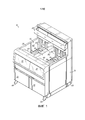
[0013] Фиг.1 - перспективный вид фритюрницы в соответствии с примером осуществления изобретения;[0013] FIG. 1 is a perspective view of a deep fryer in accordance with an embodiment of the invention;
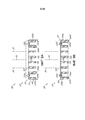
[0014] фиг.2 - схематичный вид фритюрницы на фиг.1, показывающий две варочные камеры, систему фильтрации и контроллер;[0014] Figure 2 is a schematic view of the deep fat fryer of Figure 1 showing two cooking chambers, a filtration system, and a controller;
[0015] фиг.3 - вид в разрезе целой варочной камеры, включающей в себя электрический нагревательный элемент, распорку и промывочный элемент в соответствии с примером осуществления;[0015] FIG. 3 is a cross-sectional view of an entire cooking chamber including an electric heating element, a spacer, and a flushing element according to an embodiment;
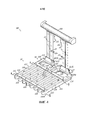
[0016] фиг.4 - перспективный вид спереди распорки, на котором распорка соединена с верхней поверхностью электрических нагревательных спиралей;[0016] Fig. 4 is a front perspective view of a spacer in which the spacer is connected to the top surface of the electric heating coils;
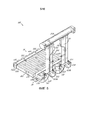
[0017] фиг.5 - перспективный вид сзади электрического нагревательного элемента и распорки на фиг.4;[0017] FIG. 5 is a rear perspective view of the electrical heating element and spacer of FIG. 4;
[0018] фиг.6 - вид в разрезе первого участка корпуса распорки по линии 6-6 на фиг.4;[0018] FIG. 6 is a cross-sectional view of a first portion of a strut body taken along line 6-6 in FIG. 4;
[0019] фиг.7 - вид в разрезе второго участка корпуса распорки по линии 7-7 на фиг.4;[0019] FIG. 7 is a sectional view of a second portion of a strut body taken along line 7-7 in FIG. 4;
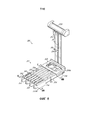
[0020] фиг.8 - перспективный вид спереди распорки в соответствии с другим примером осуществления для разделенной варочной камеры, на котором распорка соединена с верхней поверхностью электрических нагревательных спиралей;[0020] FIG. 8 is a front perspective view of a spacer in accordance with another embodiment for a split cooking chamber, in which the spacer is connected to the top surface of the electric heating coils;
[0021] фиг.8A - вид в разрезе первого участка корпуса распорки по линии 8A-8A на фиг.8;[0021] FIG. 8A is a cross-sectional view of a first portion of a spacer body taken along
[0022] фиг.8B - вид в разрезе второго участка корпуса распорки по линии 8B-8B на фиг.8;[0022] FIG. 8B is a cross-sectional view of a second portion of a strut body taken along
[0023] фиг.9 - перспективный вид промывочного элемента, расположенного на нижней стенке варочной камеры в соответствии с примером осуществления;[0023] FIG. 9 is a perspective view of a washing element disposed on the bottom wall of a cooking chamber in accordance with an embodiment;
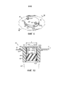
[0024] фиг.10 - вид в разрезе промывочного элемента по линии 10-10 на фиг.9;[0024] FIG. 10 is a cross-sectional view of the flushing element taken along line 10-10 in FIG. 9;
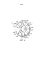
[0025] фиг.11 - перспективный вид с пространственным разделением элементов промывочного элемента на фиг.9;[0025] FIG. 11 is an exploded perspective view of the flushing element of FIG. 9;
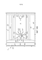
[0026] фиг.12 - вид сверху промывочного элемента на фиг.11 без крышки;[0026] FIG. 12 is a top view of the flushing element of FIG. 11 without a cover;
[0027] фиг.12A - подробный вид сверху множества потоков под давлением среды для приготовления пищи через множество распыляющих сопел промывочного элемента на фиг.12;[0027] FIG. 12A is a detailed top view of a plurality of pressurized flows of the cooking medium through a plurality of spray nozzles of the rinsing element of FIG. 12;
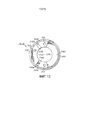
[0028] фиг.12B - вид сверху целой варочной камеры, иллюстрирующий пространственное расположение между распыляющими соплами, направляющими потоки под давлением на фиг.12A, и сливным отверстием целой варочной камеры;[0028] FIG. 12B is a top view of the entire cooking chamber illustrating the spatial arrangement between the pressure-guiding spray nozzles of FIG. 12A and the drain of the entire cooking chamber;
[0029] фиг.13 - вид сверху промывочного элемента в соответствии с другим примером осуществления;[0029] FIG. 13 is a top view of a flushing element in accordance with another embodiment;
[0030] фиг.13A - подробный вид сверху множества потоков под давлением среды для приготовления пищи через множество распыляющих сопел промывочного элемента на фиг.13;[0030] FIG. 13A is a detailed top view of a plurality of pressurized flows of the cooking medium through a plurality of spray nozzles of the rinsing element of FIG. 13;
[0031] фиг.13B - вид сверху разделенной варочной камеры, иллюстрирующий пространственное расположение между распыляющими соплами, направляющими потоки под давлением на фиг.13A, и сливным отверстием разделенной варочной камеры;[0031] FIG. 13B is a top view of a split cooking chamber illustrating the spatial arrangement between the pressure-guiding spray nozzles in FIG. 13A and an outlet of the divided cooking chamber;
[0032] фиг.14 - вид сверху промывочного элемента в соответствии с другим примером осуществления;[0032] FIG. 14 is a top view of a flushing element in accordance with another embodiment;
[0033] фиг.14A - подробный вид сверху множества потоков под давлением среды для приготовления пищи через множество распыляющих сопел промывочного элемента на фиг.14;[0033] FIG. 14A is a detailed top view of a plurality of pressurized flows of the cooking medium through a plurality of spray nozzles of the rinsing element of FIG. 14;
[0034] фиг.14B - вид сверху целой варочной камеры, иллюстрирующий пространственное расположение между распыляющими соплами, направляющими потоки под давлением на фиг.14A, и сливным отверстием целой варочной камеры;[0034] FIG. 14B is a top view of the entire cooking chamber illustrating the spatial arrangement between the pressure-guiding spray nozzles in FIG. 14A and the drain of the entire cooking chamber;
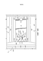
[0035] фиг.15 - перспективный вид поддона, включающего в себя сетчатый фильтр, постоянно соединенный с поддоном;[0035] FIG. 15 is a perspective view of a pallet including a strainer permanently connected to the pallet;
[0036] фиг.16 - подробный вид сетчатого фильтра на фиг.15;[0036] FIG. 16 is a detailed view of the strainer of FIG. 15;
[0037] фиг.17 - вид в разрезе поддона по линии 17-17 на фиг.16.[0037] FIG. 17 is a cross-sectional view of the pallet taken along line 17-17 in FIG. 16.
Подробное описаниеDetailed description
[0038] Примеры осуществления настоящего изобретения и их признаки и преимущества могут быть понятны путем ссылки на чертежи, на которых подобные ссылочные позиции используются для соответствующих частей на различных чертежах.[0038] The exemplary embodiments of the present invention and their features and advantages may be understood by referring to the drawings, in which like reference numbers are used for corresponding parts in the various drawings.
[0039] На фиг.1 изображен пример фритюрница 10 в соответствии с примером осуществления. Фритюрница 10 включает в себя варочные камеры 12, 14, кожух 16, панели 18, 20 управления, панели 22, 24 доступа, колеса 26 и держатель 28 корзин. Каждая из варочных камер 12, 14, кожух 16, панели 22, 24 доступа и держатель 28 корзин могут быть выполнены из нержавеющей стали, мягкой стали или некоторых других пригодных материалов. Варочные камеры 12, 14 включают в себя внутренние части 30, 32, в которые можно размещать пищевой продукт. Электрические нагревательные элементы 34, 36 соединены с распорками 38, 40 и расположены во внутренних частях 30, 32. Распорки 38, 40 выполнены с возможностью улучшения промывания варочных камер 12, 14, как будет описано более подробно ниже, без помех потоку среды 42 для приготовления пищи в варочных камерах 12, 14.[0039] FIG. 1 illustrates an example of a
[0040] Пищевые продукты могут быть размещены в варочные камеры 12, 14, например, путем опускания корзины (не показана), содержащей пищевой продукт, в варочную камеру 12, 14. При завершении цикла тепловой обработки корзина может быть удалена из варочной камеры 12, 14 и подвешена за держатель 28 корзины для обеспечения слива излишка среды 42 для приготовления пищи обратно в варочную камеру 12, 14. Каждая из варочных камер 12, 14 может быть соединена с соответствующей одной из палей 18, 20 управления для обеспечения устройства сопряжения человек-машина для приведения в действие фритюрницы 10. Панели 18, 20 управления могут принимать команды от пользователя и отображать информацию относительно состояния фритюрницы 10 пользователю. Панели 22, 24 доступа могут обеспечивать доступ к внутренней части кожуха 16, например, для обслуживания компонентов фритюрницы 10.[0040] Foods can be placed in the
[0041] Пример фритюрницы 10 показан, как имеющий отдельную панель 18, 20 управления для каждой варочной камеры 12, 14. Однако, следует понимать, что одна панель управления может быть выполнена с возможностью управления множеством варочных камер, и варианты осуществления изобретения не ограничиваются фритюрницами, имеющими отдельную панель 18, 20 управления для каждой варочной камеры 12, 14. Хотя фритюрница 10, изображенная на фиг.1, является электрически нагреваемой открытой фритюрницей, имеющим две варочные камеры 12, 14, следует также понимать, что некоторые варианты осуществления могут также использоваться с фритюрницами, работающими под давлением, а также фритюрницами, имеющими разное количество варочных камер. На фиг.1 и 3 показаны электрические нагревательные элементы 34, 36 в качестве электрических нагревательных элементов (например, электрических нагревательных спиралей, погруженных в среду 42 для приготовления пищи). Однако, газовые нагревательные элементы (например, газовая горелка и теплообменник, который передает тепло от горелки среде 42 для приготовления пищи), могут быть включены в соответствии с различными аспектами настоящего раскрытия.[0041] An example of a
[0042] Как показано на фиг.2, в дополнении к варочным камерам 12, 14 фритюрница 10 может включать в себя систему 100 управления средой для приготовления пищи и контроллер 48. Варочные камеры 12, 14, соответственно, включают в себя электрические нагревательные элементы 34, 36 (показанные схематически), датчики 50, 52 температуры, заливные отверстия 54, 56, сливные отверстия 58, 60 и промывочные элементы 44, 46. Варочные камеры 12, 14 выполнены с возможностью по меньшей мере частичного заполнения средой 42 для приготовления пищевых продуктов. Подходящие среды для приготовления пищевых продуктов могут включать в себя растительные жиры, животные жиры и/или синтетические (например, гидрированные) жиры. В то время как электрические нагревательные элементы 34, 36 показаны расположенными в варочных камерах 12, 14 для нагрева среды 42 для приготовления пищи, электрические нагревательные элементы 34, 36, в качестве альтернативы, могут быть расположены рядом с варочными камерами 12, 14 для нагрева среды 42 для приготовления пищевых продуктов.[0042] As shown in FIG. 2, in addition to
[0043] Система 100 управления средой для приготовления пищи может включать в себя спускные клапаны 102, 104, сливной трубопровод 106, поддон 108, включающий в себя узел 110 фильтров, фильтрационный насос 112, резервуар 114 для свежей среды для приготовления пищи, насос 116 для резервуара и селекторный клапан 118. Селекторный клапан 118 может включать в себя множество входных отверстий 120-122 и множество выходных отверстий 124-127. Датчик 128 температуры может быть расположен в селекторном клапане 118 или в другом подходящем местоположении для обеспечения определения контроллером 48 температуры среды 42 для приготовления пищи, проходящей через систему 100 управления средой для приготовления пищи.[0043] Cooking
[0044] Селекторный клапан 118 выполнен с возможностью селективного соединения по текучей среде одного или более входных отверстий 120-122 с одним или более выходных отверстий 124-127. Для этой цели селекторный клапан 118 может содержать поворотный клапан, имеющий поперечную вилку (не показана), соединенную с электродвигателем 130. Электродвигатель 130 может заставлять селекторный клапан 118 соединять по текучей среде выбранное входное отверстие с выбранным выходным отверстием путем поворота поперечной вилки в одно из множества заданных положений. В альтернативном варианте осуществления изобретения селекторный клапан 118 может содержать узел клапанов, которые выполнены с возможностью обеспечения заданного селективного соединения по текучей среде в соответствии с сигналами с контроллера 48. В этом альтернативном варианте осуществления селекторный клапан 118 может содержать узел, включающий в себя множество клапанов, соединенных с трубопроводом.[0044]
[0045] И фильтрационный насос 112 и насос 116 для резервуара могут включать в себя впускное отверстие 132, 134 на стороне всасывания фильтрационного насоса 112, и выпускное отверстие 136, 138 на стороне нагнетания насоса. Впускное отверстие 132 фильтрационного насоса 112 может быть соединено по текучей среде с поддоном 108 с помощью узла 110 фильтров, и выпускное отверстие 136 фильтрационного насоса 112 может быть соединено по текучей среде с входным отверстием 120 селекторного клапана 118. Приведение в действие фильтрационного насоса 112 может вызывать всасывание среды 42 для приготовления пищи из поддона 108, узла 110 фильтров и передачу в селекторный клапан 118. Селекторный клапан 118 может в свою очередь направлять отфильтрованную среду 42 для приготовления пищи в одну из варочных камер 12, 14 для повторного использования и/или в сливное отверстие 140 для удаления.[0045] Both the
[0046] Хотя узел 110 фильтров изображен соединенным с впускным отверстием 132 фильтрационного насоса 112 в примере осуществления, показанном на фиг.2, следует понимать, что система 100 управления средой для приготовления пищи не ограничивается конкретным расположением изображенных компонентов. Например, узел 110 фильтров может быть соединен с выпускным отверстием 136 фильтрационного насоса 112, а не с впускным отверстием 132, так что среда 42 для приготовления пищи проталкивается через узел 110 фильтров, а не всасывается через узел 110 фильтров. В любом случае узел 110 фильтров может включать в себя кожух, выполненный с возможностью приема фильтра для фильтрации среды 42 для приготовления пищи. В соответствии с примером осуществления сетчатый фильтр 148 может быть постоянно соединен с поддоном 108. Регулярное использование фильтроциклов для очистки среды 42 для приготовления пищи может уменьшить потребление среды 42 для приготовления пищи и увеличить работоспособность фритюрницы 10 путем подачи горячей отфильтрованной среды 42 для приготовления пищи в варочные камеры 12, 14.[0046] Although the
[0047] Впускное отверстие 134 насоса 116 для резервуара может быть соединено по текучей среде с резервуаром 114, и выпускное отверстие 138 насоса 116 для резервуара может быть соединено по текучей среде с входным отверстием 121 селекторного клапана 118. Приведение в действие насоса 116 для резервуара может вызывать всасывание среды 42 для приготовления пищи из резервуара 114 и подачу в селекторный клапан 118. Селекторный клапан 118 может, в свою очередь, направлять свежую среду 42 для приготовления пищи в одну из варочных камер 12, 14 для повторного заполнения и/или добавления среды 42 для приготовления пищи. Заливное отверстие 142 может быть соединено с входным отверстием селекторного клапана 118 для обеспечения добавления среды 42 для приготовления пищи в резервуар 114. Система 100 управления средой для приготовления пищи может дополнительно включать в себя стопорные клапаны 143-147, которые предотвращают прохождение среды 42 для приготовления пищи обратно из варочных камер 12, 14 в селекторный клапан 118, или из селекторного клапана 118 либо в фильтрационный насос 112, насос 116 для резервуара либо в заливное отверстие 142.[0047] The
[0048] Контроллер 48 может находиться в сообщении с электрическими нагревательными элементами 34, 36 и датчиками 50, 52 температуры каждой из варочных камер 12, 14, а также со сливными клапанами 102, 104, фильтрационным насосом 112, насосом 116 для резервуара, датчиком 128 температуры и электродвигателем 130 селекторного клапана 118. Контроллер 48 может управлять различными циклами тепловой обработки и технического обслуживания фритюрницы 10 посредством передачи сигналов на эти компоненты фритюрницы 10 и приема сигналов с этих компонентов фритюрницы 10. Контроллер 48 может быть также соединен с панелями 18, 20 управления для отображения рабочей информации на фритюрнице 10 и приема входных данных от пользователя фритюрницы 10. Контроллер 48 может регулировать температуру среды 42 для приготовления пищи в каждой варочной камере 12, 14 посредством селективного приведения в действие соответствующего электрического нагревательного элемента 34, 36 и может управлять фильтрацией и добавлением масла для жарки посредством селективного приведения в действие спускных клапанов 102, 104, фильтрационного насоса 112, насоса 116 для резервуара и электродвигателя 130 селекторного клапана 118.[0048]
[0049] На фиг.3-7 показан пример осуществления конструкции 200, в которой распорка 38 установлена в верхней части электрического нагревательного элемента 34, как будет описано более подробно ниже. Хотя фиг.3 - вид в разрезе варочной камеры 12, эти принципы одинаково применяются к варочной камере 14 и ее соответствующим компонентам (например, электрическому нагревательному элементу 36, распорке 40 и промывочному элементу 46). Для краткости распорка 38 относительно варочной камеры 12 предназначена для соответствия распорки 40 относительно варочной камеры 14.[0049] FIGS. 3-7 show an exemplary embodiment of a
[0050] Варочная камера 12 включает в себя множество боковых стенок. Как показано, множество боковых стенок включает в себя первую и вторую боковые стенки 62, 64 (показанные на фиг.1), первую и вторую торцевые стенки 66, 68 и нижнюю стенку 70, вместе образующие внутреннюю часть 30. Специалисты в данной области техники должны понимать, что множество боковых стенок может включать в себя больше или меньше боковых стенок при желании. Среда 42 для приготовления пищи может быть размещена во внутренней части 30 и заполнена до заданного уровня (например, линии 72 заполнения). Специалисты в данной области техники также должны понимать, что первая и вторая боковые стенки 62, 64, первая и вторая торцевые стенки 66, 68 и нижняя стенка 70 могут включать в себя множество секций стенок, которые вместе образуют каждую соответствующую стенку, обеспечивая сгиб или наклон каждой соответствующей стенки при желании. Конкретно, как показано на фиг.3, первая торцевая стенка 66 включает в себя наклонные секции 66a, 66b стенки и вертикальные секции 66c, 66d стенки. Подобным образом, вторая торцевая стенка 68 включает в себя наклонную секцию 68a и вертикальные секции 68b, 68c стенки. Подобным образом, как показано на фиг.12, первая боковая стенка 62 включает в себя наклонную секцию 62a стенки и вертикальную секцию 62b, и вторая боковая стенка 64 включает в себя наклонную секцию 64a и вертикальную секцию 64b стенки.[0050] The
[0051] Во внутренней части 30 варочной камеры 12 расположен электрический нагревательный элемент 34. Электрический нагревательный элемент 34 включает в себя две электрических нагревательных спирали 202, расположенных в змеевидной конфигурации. Электрические нагревательные спирали 202 включают в себя верхнюю и нижнюю поверхности 204, 206. Как показано на фиг.3-5, электрический нагревательный элемент 34 включает в себя поворотную конструкцию 208, которая соединена со второй торцевой стенкой 68, которая обеспечивает поворот вверх и вниз электрического нагревательного элемента 34 при желании. Электрические нагревательные спирали 202 отделены от поворотной конструкции 208 одним или более кронштейнами 211. Одна или более проволок 212 могут быть соединены с кронштейнами 211 с помощью соединительных элементов 214 (например, крепежных скоб) или крепежных элементов (например, винтов). Как показано на фиг.4, электрические нагревательные спирали 202 включают в себя восемь обычно параллельных рядов 218, которые расположены на заданном расстоянии от соседнего ряда, которое может быть одинаковым или изменяться от ряда к ряду. Петлевые участки 220 соединяют соседние обычно параллельные ряды 218.[0051] In the interior 30 of the
[0052] Распорка 38 соединена с верхними поверхностями 204 электрических нагревательных спиралей 202 и выполнена с возможностью поддержания обычно параллельных рядов 218 электрических нагревательных спиралей 202 в заданной змеевидной конфигурации. Более конкретно, нижняя поверхность 219 распорки 38 может находиться в непосредственном контакте с верхними поверхностями 204 электрических нагревательных спиралей 202. Как показано, распорка 38 может также отделять электрические нагревательные спирали 202 на заданном расстоянии от нижней стенки 70, которая образует дополнительный зазор для промывочного элемента 44 для распыления среды 42 для приготовления пищи под давлением между нижней стенкой 70 варочной камеры 12 и нижними поверхностями 206 электрических нагревательных спиралей 202.[0052] The
[0053] Как более ясно показано на перспективных видах спереди и сзади на фиг.4 и 5, распорка 38 включает в себя первый и второй участки 222, 224 корпуса. Первый участок 222 корпуса обычно расположен рядом с первой торцевой стенкой 66, и второй участок 224 корпуса обычно расположен рядом со второй торцевой стенкой 68. Первый участок 222 корпуса может включать в себя обращенные вниз первую и вторую боковые стенки 222a-b, которые проходят вокруг верхних поверхностей 204 электрических нагревательных спиралей 202 к нижней стенке 70. Подобным образом, второй участок 224 корпуса может включать в себя обращенные вниз первую и вторую боковые стенки 224a-b, которые проходят по верхним поверхностям 204 электрических нагревательных спиралей 202 к нижней стенке 70. В примере осуществления свыше 50% первого и второго участков 222, 224 корпуса распорки 38 расположены над верхними поверхностями 204 электрических нагревательных спиралей 202 и на расстоянии от нижней стенки 70 варочной камеры 12. Как показано на фиг.4 и 5, второй участок 224 корпуса может включать в себя один или более верхних выступов 221, которые закреплены на кронштейнах 211 электрического нагревательного элемента 34 с помощью соединительных элементов 223a-b (например, хомутов) и крепежных элементов 225 (например, винтов).[0053] As shown more clearly in the front and rear perspective views in FIGS. 4 and 5, the
[0054] На фиг.6 и 7 показаны два соответствующих вида в разрезе на фиг.4, на которых распорка 38 соединена с электрическим нагревательным элементом 34 с помощью множества соединительных элементов 226a-h (например, хомутов, имеющих крючки 228a-h, которые проходят вокруг нижних поверхностей 206 электрических нагревательных спиралей 202). Хомуты соединены с возможностью съема с разделительным стержнем 38 с помощью крепежных элементов 230a-h (например, винтов). Как показано на фиг.6, крючки 228b-c соединительных элементов 226b-c имеют проходящие вниз выступы, которые могут находиться в непосредственном контакте с нижней стенкой 70 варочной камеры 12, заставляя нижние поверхности 206 электрических нагревательных спиралей 202 находиться на заданном расстоянии от нижней стенки 70. Более конкретно, соединительные элементы 226a-d соединяют первый участок 222 корпуса с передними участками 232 электрических нагревательных спиралей 202, и соединительные элементы 226e-h соединяют второй участок 224 корпуса с задними участками 234 электрических нагревательных спиралей 202. Хотя не показано, предусмотрено, что некоторые или все соединительные элементы могут быть образованы как одно целое с распоркой 38. Кроме того, хотя не показано, электрический нагревательный элемент 34 может быть постоянно соединен с распоркой 38 с помощью сварных швов или другой постоянной крепежной конструкции. Дополнительные хомуты 236 (показанные на фиг.4 и 5) могут быть использованы для удержания датчиков температуры в заданном положении рядом с электрическими нагревательными спиралями 202.[0054] FIGS. 6 and 7 show two respective cross-sectional views of FIG. 4 in which the
[0055] Расположение распорки 38 таким образом, чтобы находиться, по существу, полностью над электрическим нагревательным элементом 34, и так чтобы имелся зазор между нижней стенкой 70 варочной камеры 12 и нижней поверхностью 219 распорки 38, повышает эффективность очистки и значительно увеличивает полезный объем варочной камеры 12 без отрицательного влияния на электрический нагревательный элемент 34, который имеет приблизительно тот же размер. В результате, если распорка 38 расположена в основном под электрическим нагревательным элементом 34, распорку 38 вероятно нужно было бы поднять на 0,25 дюйма или более для достижения подобной эффективности, что уменьшило бы полезный объем варочной камеры 12. Как показано, параллельные ряды 218 электрических нагревательных спиралей 202 расположены спереди-назад в направлении потока, так что любое препятствие потоку минимизировано, поскольку распорка 38 проходит приблизительно перпендикулярно к основному пути потока промывочного элемента 44.[0055] Positioning the
[0056] На фиг.8-8B показана конструкция 300, включающая в себя электрический нагревательный элемент 301, соединенный с распоркой 310, для разделенной варочной камеры 502, 504 (показанной на фиг.13B) в соответствии с другим примером осуществления. Распорка 310 и электрический нагревательный элемент 301 включают в себя многие из тех же элементов, что и описанный выше вариант осуществления (элементы были обозначены подобными ссылочными позициями в серии 300, в которой элементы, по существу, подобны или идентичны). Например, данный вариант осуществления также включает в себя электрическую нагревательную спираль 302, верхнюю и нижнюю поверхности 304, 306 электрической нагревательной спирали 302, поворотную конструкцию 308, кронштейны 311, проволоку 312, соединительный элемент 314, крепежных элемент 316, параллельные ряды 318 электрической нагревательной спирали 302, нижнюю поверхность 319 распорки 310, петлевидные участки 320 электрической нагревательной спирали 302, первый участок 322 корпуса, первую и вторую боковые стенки 322a-b первого участка 322 корпуса, второй участок 324 корпуса, первую и вторую боковые стенки 324a-b второго участка 324 корпуса, крепежные элементы 325, соединительные элементы 326a-d, имеющие крючки 328a-d, крепежные элементы 330a-d, передний участок 332 электрической нагревательной спирали 302 и задний участок 334 электрической нагревательной спирали 302.[0056] FIGS. 8-8B show a
[0057] Хотя многие из этих элементов имеют незначительно измененные формы или профили в данном варианте осуществления, распорка 310 и ее элементы функционируют, как описано выше, за исключением отличий, описанных дополнительно подробно ниже (подробное описание этих идентичных или, по существу, подобных элементов в основном не повторяется в данном документе для краткости). В данном варианте осуществления распорка 310 показана для разделенной варочной камеры (показанной на фиг.13B) по сравнению с фиг.3-7, на которых показана распорка 38, 40 для полноразмерной варочной камеры 12, 14.[0057] Although many of these elements have slightly modified shapes or profiles in this embodiment, the
[0058] Как показано, первый участок 322 корпуса включает в себя множество отверстий 340 различных размеров, которые расположены между параллельными рядами 318 электрической нагревательной спирали 302. Кроме того, второй участок 324 корпуса включает в себя большое отверстие 342. Множество отверстий 340 и большое отверстие 342 выполнены с возможностью увеличения потока среды 42 для приготовления пищи при его перемещении за первый и второй участки 322, 324 корпуса. В соответствии с примером осуществления первый участок 322 корпуса поддерживает вверху электрическую нагревательную спираль 302, так как корзина (не показана) будет вытеснять электрическую нагревательную спираль 302 вниз к нижней поверхности 570, 580 разделенных варочных камер 502, 504, и данная конструкция предотвращает сгибание электрической нагревательной спирали 302. Второй участок 324 корпуса может иметь отверстие 342 для обеспечения того, чтобы второй участок 324 корпуса должным образом устанавливался на электрической нагревательной спирали 302.[0058] As shown, the
[0059] В соответствии с другим аспектом на фиг.9-13 показаны различные виды промывочного элемента 44, соединенного с нижней стенкой 70 варочной камеры 12.[0059] In accordance with another aspect, FIGS. 9-13 show various views of a
[0060] Как конкретно показано на фиг.9-11, промывочный элемент 44 включает в себя корпус 412 с нижним участком 414 и верхним участком 416. Как показано, промывочный элемент 44 также включает в себя крышку 418, которая закреплена с возможностью съема на верхнем участке 416 с помощью одного или более крепежных элементов 420 для обеспечения выполнения периодического технического обслуживания при необходимости для удаления накопления и/или засоров. Верхний участок 416 промывочного элемента 44 имеет круглое поперечное сечение. Общая высота промывочного элемента 44 может составлять 1,375 дюймов без крышки 418. Как показано, нижний и верхний 414, 416 участки включают в себя проход 422, который соединен по текучей среде с заливным отверстием 423, выполненным с возможностью вмещения среды 42 для приготовления пищи. Проход 422 может иметь диаметр D около 0,984 дюйма, как показано на фиг.12A, 13A и 14A. Хотя резьбовое соединение 425 между нижним участком 414 корпуса и заливным отверстием 423 показано на фиг.10, множество других способов соединения также предусмотрены в альтернативных вариантах осуществления.[0060] As specifically shown in FIGS. 9-11, the flushing
[0061] Как показано на фиг.10, верхний участок 416 промывочного элемента 44 проходит над нижней стенкой 70 варочной камеры 12 и включает в себя распыляющие сопла 424a-g, соединенные по текучей среде с проходом 422. Как показано, распыляющие сопла 424a-g имеют выпускные отверстия 436a-g распылительного канала с высотой H около 0,125 дюйма. Высота H выпускных отверстий 436a-g распылительного канала может изменяться в соответствии с различными вариантами осуществления, так как это может быть желательным для установления взаимосвязи между скоростью среды 42 для приготовления пищи и размерами распыляющих сопел 424a-g. Например, при использовании насоса 8 GPM, высота H 0,125 дюйма была определена во время испытания для обеспечения достаточной скорости для удаления частиц при предотвращении выхода среды 42 для приготовления пищи во время промывания. Если скорость среды 42 для приготовления пищи необходимо увеличить или уменьшить, может быть предпочтительным регулировка размеров распыляющих сопел 424a-g, таких как высота H выпускных отверстий 436a-g распылительного канала, соответственно. Например, меньший насос может использоваться в сочетании с уменьшенной высотой H, в то время как больший насос может использоваться в сочетании с увеличенной высотой H.[0061] As shown in FIG. 10, the
[0062] Специалисты в данной области техники должны понимать, что эти размеры могут изменяться на основании размера или размеров конкретной емкости для жарки и заданных параметров потока. Распыляющие сопла 424a-g выполнены с возможностью разделения среды 42 для приготовления пищи на множество потоков 438a-g под давлением, которые направлены между нижней стенкой 70 варочной камеры 12 и электрическим нагревательным элементом 34. Крышка 418 направляет среду 42 для приготовления пищи из прохода 422 в распыляющие сопла 424a-g. Промывочный элемент 44 может также включать в себя выступ 428, который может находиться в непосредственном контакте с нижней стенкой 70 и способствует поддержанию расположения промывочного элемента 44.[0062] Those of skill in the art will understand that these dimensions may vary based on the size or dimensions of a particular frying container and given flow conditions. Spray
[0063] Фиг.11 - перспективный вид с пространственным разделением элементов промывочного элемента 44, на котором крепежные элементы 420 включают в себя два винта, которые вставляются через отверстия 430 в крышке 418 и размещаются с помощью внутренних резьб 432 в верхнем участке 416 промывочного элемента 44. Как использовано в данном документе, крепежные элементы 420 предназначены для включения в себя болтов, тяг, хомутов или любого другого подходящего крепежного элемента или их сочетаний. Кроме того, хотя не показано, специалисты в данной области техники должны понимать, что крышка 418 и верхний участок 416 могут быть образованы как одно целое или могут быть постоянно закреплены вместе с помощью клея и/или сварки.[0063] FIG. 11 is an exploded perspective view of flushing
[0064] Как показано на фиг.12, распыляющие сопла 424a-g данного варианта осуществления включают в себя первую, вторую, третью, четвертую, пятую, шестую и седьмую распыляющие сопла 424a-g. Распыляющие сопла 424a-g, соответственно, включают в себя первое, второе, третье, четвертое, пятое, шестое и седьмое впускные отверстия 434a-g распылительного канала, соединенные по текучей среде с проходом 422, и первое, второе, третье, четвертое, пятое, шестое и седьмое выпускные отверстия 436a-g распылительного канала соединены по текучей среде с впускными отверстиями 434a-g распылительного канала. Впускные отверстия 434a-g распылительного канала выполнены с возможностью образования первого, второго, третьего, четвертого, пятого, шестого и седьмого потоков 438a-g под давлением среды 42 для приготовления пищи для выхода из промывочного элемента 44 в заданные области варочной камеры 12.[0064] As shown in FIG. 12, the
[0065] Как показано на фиг.12A и 12B, распыляющие сопла 424a-g отделены заданными углами A1-A7 друг от друга вокруг периферии 426 верхнего участка 416 промывочного элемента 44 для ориентации распыляющих сопел 424a-g для распыления потоков 438a-g под давлением среды 42 для приготовления пищи в заданные области варочной камеры 12. Заданные области могут включать в себя углы 444a-d варочной камеры 12 рядом с нижней стенкой 70 и по нижней стенки 70 к первой и второй торцевым стенкам 66, 68. Как показано на фиг.12B, первая и вторая распыляющие сопла 424a-b направлены к первой торцевой стенке 66, в то время как третья, четвертая, пятая, шестая и седьмая распыляющие сопла 424c-g направлены ко второй торцевой стенке 68.[0065] As shown in FIGS. 12A and 12B, the
[0066] Как показано на фиг.12B, первое распыляющее сопло 424a направлено в первый угол 444a между нижней стенкой 70, передней торцевой стенкой 66 и второй боковой стенкой 64. Второе распыляющее сопло 424b направлена во второй угол 444b между нижней стенкой 70, передней торцевой стенкой 66 и первой боковой стенкой 62. Третье распыляющее сопло 424c направлено к первой боковой стенке 62. Четвертое распыляющее сопло 424d направлено в третий угол 444c между нижней стенкой 70, второй торцевой стенкой 68 и первой боковой стенкой 62. Пятое распыляющее сопло 424e направлено по центру нижней стенки 70 ко второй торцевой стенке 68 для выталкивания крошек в сливное отверстие 58. Шестое распыляющее сопла 424f направлена в четвертый угол 444d между нижней стенкой 70, первой торцевой стенкой 66 и второй боковой стенкой 64. Седьмое распыляющее сопло 424g направлено на вторую боковую стенку 64. Промывочный элемент 44 расположен ближе к первой торцевой стенке 66 по сравнению со второй торцевой стенкой 68 и обычно находится посередине между первой и второй боковыми стенками 62, 64.[0066] As shown in FIG. 12B, the
[0067] Ссылаясь на целую варочную камеру 12 на фиг.12B, распыляющие сопла 424a-g расположены под заданными углами и имеют конкретную ширину на верхнем участке 416. Как показано на фиг.12B, нижеследующие углы взяты относительно центра соответствующих распыляющих сопел 424: A1 составляет около 126°, A2 и A7 составляют около 47°, и A3-A6 составляют около 35°. Кроме того, первое, второе, третье и седьмое распыляющие сопла 424a-c, 424g имеют значения ширины W1-W3, W7 около 0,15 дюйма, четвертое и шестое распыляющие сопла 424d, 424f имеют ширину W4, W6 около 0,25 дюйма, и пятое распыляющее сопло 424e имеет ширину около 0,18 дюйма. Кроме того, значения ширины W1-2 первого и второго распыляющих сопел 424a-b могут иметь уменьшенную ширину или конкретную форму, которые, как подразумевают, засоряются первыми, если происходит засор. Это должно предотвращать выпуск потоков с более высоким давлением масла для приготовления пищи к первой торцевой стенке 66 при возникновении засора, что иначе бы могло привести к разбрызгиванию масла в направлении, в котором пользователь стоял бы во время использования фритюрницы 10.[0067] Referring to the
[0068] Эти значения являются примерными, так как точное количество распыляющих сопел 424a-g может изменяться, и диапазон соответствующих углов может быть между распыляющими соплами 424a-g, которые могут иметь соответствующую ширину, в зависимости от областей, которые являются труднодоступными для очистки и должны достигаться средой 42 для приготовления пищи, проходящей из промывочного элемента 44. По существу, специалисты в данной области техники должны понимать, что размеры, описанные в данном документе относительно промывочного элемента 44, конкретно относятся к размеру и конфигурации конкретной используемой варочной камеры 12. Например, конструкция разделенной варочной камеры отличается от конструкции цельной варочной камеры, описанной в данном варианте осуществления. Кроме того, специалисты в данной области техники должны понимать, что варочная камера с несколько другими размерами может иметь несколько другую конструкцию промывочного элемента и соответствующие углы. Расстояние и углы между выпускными отверстиями 436a-g распылительного канала, ширина и форма каждых выпускных отверстий 436a-g распылительного канала, форма верхнего участка 416, высота H и другие геометрические параметры могут быть выбраны на основании того, где частицы накапливаются в варочной камере 12, т.е., областей, которые являются наиболее труднодоступными для очистки. Для этой цели примеры, приведенные в этих примерах осуществления, обеспечивают решения с учетом конкретных размера и конфигурации варочных камер, показанных на чертежах.[0068] These values are approximate as the exact number of
[0069] Промывочный элемент 44 обеспечивает многие преимущества относительно работы фритюрницы 10. Например, промывочный элемент 44 эффективно удаляет частицы из варочной камеры 12 и перемещает их в сливное отверстие 58. Это увеличивает возможность фритюрницы 10 быстро и автоматически удалять частицы из варочной камеры 12. Это приводит к минимальному влиянию на работу фритюрницы 10 и освобождает время для приготовления дополнительных пищевых продуктов путем уменьшения перерыва в работе вследствие ручной очистки устройства. Кроме того, промывочный элемент 44 выполнен с возможностью управления направлением потока среды 42 для приготовления пищи и обеспечения заданной скорости для удаления частиц и других отходов из заданных областей варочной камеры 12, конкретно областей, подобных углам, в которых такие частицы и отходы будут стремиться собираться наиболее быстро. Скорость, создаваемая узкими выпускными отверстиями 436a-g распылительного канала, улучшает удаление частиц из варочной камеры 12 по сравнению с системами и способами промывания обычной фритюрницы. В результате ручное промывание варочной камеры 12, хотя не полностью исключено, требуется менее часто по сравнению с предшествующими системами и способами промывания фритюрницы.[0069] The rinsing
[0070] На фиг.13-13B подробно показаны первый и второй промывочные элементы 510, 512 в соответствии с другим примером осуществления варочной камеры, которая разделена на две варочные камеры 502, 504. Первый и второй промывочные элементы 510, 512 включают в себя многие из тех же элементов, что и ранее описанный вариант осуществления (промывочный элемент 44), и эти элементы были обозначены подобными ссылочными позициями в серии 500, в которой элементы являются, по существу, подобными и идентичными. Например, каждый из промывочных элементов 510, 512 данного варианта осуществления также включает в себя верхний участок 516, крышку 518 и крепежные элементы 520, проход 522, первое, второе и третье распыляющие сопла 524a-c, выступ 528, внутренние резьбы 532, первое, второе и третье впускные отверстия 534a-c распылительного канала и первое, второе и третье выпускные отверстия 536a-c распылительного канала. Хотя многие из этих элементов имеют слегка измененные формы или профили в данном варианте осуществления, промывочные элементы 510, 512 и их элементы работают, как описано выше, за исключением отличий, описанных дополнительно подробно ниже (подробное описание этих идентичных или, по существу, подобных элементов в основном не повторяется в данном документе для краткости).[0070] FIGS. 13-13B detail first and
[0071] В данном варианте осуществления разделенная варочная камера 502 включает в себя множество боковых стенок (включая первую и вторую боковые стенки 562, 564 и первую и вторую торцевые стенки 566, 568), соединенных с нижней стенкой 570 и проходящих вверх от нижней стенки 570. Первая и вторая боковые стенки 562, 564, первая и вторая торцевые стенки 566, 568 и нижняя стенка 570 вместе окружают внутреннюю часть, выполненную с возможностью вмещения среды 42 для приготовления пищи. Разделенная варочная камера 504 включает в себя множество боковых стенок (включая первую и вторую боковые стенки 572, 574 и первую и вторую торцевые стенки 576, 578), соединенных с нижней стенкой 580 и проходящих вверх от нижней стенки 580. Первая и вторая боковые стенки 572, 574, первая и вторая торцевые стенки 576, 578 и нижняя стенка 580 вместе окружают внутреннюю часть, выполненную с возможностью вмещения среды 42 для приготовления пищи.[0071] In this embodiment, the divided
[0072] Специалисты в данной области техники должны понимать, что множество боковых стенок могут включать в себя больше или меньше стенок при желании, и первая и вторая боковые стенки 572, 574, первая и вторая торцевые стенки 576, 578 и нижняя стенка 580 могут включать в себя множество секций стенок (например, наклонные секции стенок 566a-b, 568a-b и 578a и вертикальные секции 562a, 564a, 566c, 568b-c, 572a, 574a, 576c и 578b-c), которые вместе образуют каждую соответствующую стенку, обеспечивая сгиб, наклон каждой соответствующей стенки, или вертикальный элемент при желании.[0072] Those of skill in the art should understand that the plurality of side walls may include more or less walls if desired, and the first and
[0073] В данном варианте осуществления первый промывочный элемент 510 включает в себя первый, второй и третий потоки 538a-c под давлением, направленные в разделенную варочную камеру 502, в то время как второй промывочный элемент 512 включает в себя первый, второй и третий потоки 540a-c под давлением, направленные в разделенную варочную камеру 504. Первое, второе и третье выпускные отверстия 536a-c распылительного канала первого и второго промывочных элементов 510, 512 выполнены с возможностью обеспечения выхода первого, второго и третьего потоков 538a-c, 540a-c под давлением среды 42 для приготовления пищи из промывочных элементов 510, 512 в заданные области разделенных варочных камер 502, 504, как будет описано более подробно со ссылкой на фиг.13B.[0073] In this embodiment, the
[0074] Распыляющие сопла 524a-g для разделенных варочных камер 502, 504 расположены под заданными углами вокруг периферии 526 верхнего участка 516 и имеют конкретные значения ширины на верхнем участке 516. В изображенном варианте осуществления углы взяты относительно центра распыляющих сопел 524a-c. Как показано на фиг.13A, A1 составляет около 110°, и A2 и A3 составляют около 125° окружности круглого сечения. Первое и второе распыляющие сопла 524a-b имеют значения ширины W1-W2 около 0,15 дюйма. Эти значения являются примерными, так как это является предпочтительным для оптимального сочетания скорости потока и размера отверстия, так как количество распыляющих сопел 524a-c может изменяться, и диапазон соответствующих углов может быть между распыляющими соплами 524a-c, которые могут иметь соответствующую ширину, в зависимости от областей, которые являются труднодоступными для очистки и должны достигаться средой 42 для приготовления пищи, проходящей из первого промывочного элемента 510. Как показано, значения ширины W1-W2 первого и второго распыляющих сопел 524a-b могут иметь уменьшенную ширину или конкретную форму, которые будут засоряться перед засором третьего распыляющего сопла 524c, что является предпочтительным по тем же причинам, изложенным выше относительно варианта осуществления на фиг.12-12B.[0074] The
[0075] Как показано на фиг.13A, размер третьего выпускного отверстия 536c распылительного канала больше размера третьего впускного отверстия 534c распылительного канала, с образованием формы широкого распыла (расходящейся веерной формы). В качестве альтернативы, хотя не показано, одно или более распыляющих сопел 424a-g могут иметь форму узконаправленного распыла (сходящуюся веерную форму), на котором размер выпускного отверстия распылительного канала меньше размера впускного отверстия распылительного канала. Как показано на фиг.13B первое и второе распыляющие сопла 524a-b направлены к первой торцевой стенке 566, 576 и имеют меньшие выпускные отверстия 536a-b распылительного канала, чем третье распыляющее сопло 524c, направленное в основном по длине нижней стенки 570, 580 ко второй торцевой стенке 568, 578.[0075] As shown in Fig. 13A, the size of the third spray passage outlet 536c is larger than the size of the third
[0076] В данном варианте осуществления относительно первого промывочного элемента 510 первое распылительное сопло 524a направлено в первый и пятый углы 544a, 544e между нижней стенкой 570, первой торцевой стенкой 566 и второй боковой стенкой 564. Второе распыляющее сопла 524b направлено во второй и шестой углы 544b, 544f между нижней стенкой 570, первой торцевой стенкой 566 и первой боковой стенкой 562. Третье распыляющее сопло 524c имеет угол A4 около 140° и образует форму большого распыления через нижнюю стенку 570 разделенной варочной камеры 502 и к третьему и четвертому углам 544c, 544d. Форма более широкого распыла выполнена с возможностью очистки этих третьего и четвертого углов 544c, 544d, также с образованием основного большого потока масла по длине нижней стенки 570 для перемещения любой макрочастицы, смываемой с углов и кромок варочной камеры, в соответствующее сливное отверстие 558, и это обеспечивает то, что распыляющие сопла 524a-c являются достаточно большими для уменьшения риска засорения частицами (например, закристаллизованным маслом/комочками), оставаясь способными направлять поток в заданные области, обеспечивая наилучшую моющую способность.[0076] In this embodiment, with respect to the
[0077] Относительно второго промывочного элемента 512 первое распыляющее сопло 524a направлено в первый и пятый углы 546a, 546e между нижней стенкой 570, первой торцевой стенкой 566 и второй боковой стенкой 564. Второе распыляющее сопло 524b направлено во второй и шестой углы 546b, 546f между нижней стенкой 570, первой торцевой стенкой 566 и первой боковой стенкой 562. Третье распыляющее сопло 524c проходит под углом 140° и образует форму большого распыления через нижнюю стенку 570 разделенной варочной камеры 504 к третьему и четвертому углам 546c, 546d. Форма более широкого распыления выполнена с возможностью очистки этих третьего и четвертого углов 546c, 546d, также образуя основной большой поток масла по длине нижней стенки 570 для перемещения любой макрочастицы, смываемой с углов и кромок варочной камеры, в соответствующее сливное отверстие 558. Углы 544a-d, 546a-d образованы вдоль соединений нижней стенки 570, 580 и стенок рядом с нижней стенкой 570, 580.[0077] With respect to the
[0078] На фиг.14 и 14A подробно изображен промывочный элемент 610 для полноразмерной варочной камеры 12, 14 в соответствии с другим примером осуществления. Этот промывочный элемент включает в себя многие из тех же элементов, что и описанный ранее вариант осуществления (промывочный элемент 44), и эти элементы были обозначены подобными ссылочными позициями в серии 600, в которой элементы являются, по существу, подобными и идентичными. Например, промывочный элемент 610 данного варианта осуществления также включает верхний участок 616, крышку 618, крепежные элементы 620, проход 622, первое, второе, третье, четвертое, пятое, шестое и седьмое распыляющие сопла 624a-g, выступ 628, внутренние резьбы 632, первое, второе, третье, четвертое, пятое, шестое и седьмое впускные отверстия 634a-g распылительного канала, первое, второе, третье, четвертое, пятое, шестое и седьмое выпускные отверстия 636a-g распылительного канала и первый, второй, третий, четвертый, пятый, шестой и седьмой потоки 638a-g под давлением.[0078] FIGS. 14 and 14A illustrate in detail a
[0079] В этом варианте осуществления для смывания отходов из целой варочной камеры 12, распыляющие сопла 624a-g расположены под заданными углами вокруг периферии 626 верхнего участка 616 и имеют конкретные значения ширины на верхнем участке 616. В изображенном варианте осуществления нижеследующие углы взяты относительно центра соответствующих распыляющих сопел 624a-g: A1 составляет около 90°, A2 и A7 составляют около 65°, и A3-A6 составляют около 35°. A8-A13 имеют расходящиеся стенки с отличающимися углами, например, как показано, A8 и A12 составляют около 20°, A9 и A11 составляют около 5°, и A10 и A13 составляют около 4°. Второе распыляющее сопло 624b имеет ширину W1 около 0,15 дюйма. Эти значения являются примерными, так как количество распыляющих сопел 624a-g может изменяться, и диапазон соответствующих углов может быть между распыляющими соплами 624a-g, которые могут иметь соответствующую ширину, в зависимости от областей, которые являются труднодоступными для очистки и должны достигаться средой 42 для приготовления пищи, проходящей из промывочного элемента 610. Как показано на фиг.14A, первое и второе распыляющие сопла 624a-b могут иметь уменьшенную ширину или иметь конкретную форму, которые засоряются первыми, что является предпочтительным по тем же причинам, изложенным выше относительно варианта осуществления на фиг.12-12B.[0079] In this embodiment, for flushing waste from the
[0080] Как показано на фиг.14B, первое, второе, четвертое и шестое выпускные отверстия 636a-b, 636d, 636g распылительного канала направлены в углы 644a-d варочной камеры 12. Углы 644a-d образованы вдоль соединений нижней стенки 70 и множества боковых стенок рядом с нижней стенки 70. Подобно предыдущему варианту осуществления размер третьего выпускного отверстия 636c распылительного канала больше размера каждого из первого и второго выпускных отверстий 636a-b распылительного канала. Третье выпускное отверстие 636c распылительного канала направлено по нижней стенке 70 ко второй торцевой стенке 68. Как показано, размер первого выпускного отверстия 636a распылительного канала меньше размера второго выпускного отверстия 636b распылительного канала. В связи с этим будет понятно на основании данного и предыдущего вариантов осуществления, что каждое из впускных отверстий и выпускных отверстий распылительного канала могут отличаться по размеру друг от друга в зависимости от конкретных потребностей при промывании конкретной геометрии варочной камеры.[0080] As shown in Fig. 14B, the first, second, fourth and sixth spray port outlets 636a-b, 636d, 636g of the spray passage are directed to corners 644a-d of the
[0081] На фиг.15-17 изображена система 710 фильтрации, включающая в себя сетчатый фильтр 148, постоянно соединенный с поддоном 108. Предполагается, что отверстия 711 в сетчатом фильтре 148 засоряются первыми для обеспечения начальной фильтрации для обеспечения того, чтобы частицы не проходили в части вниз по потоку системы 710 фильтрации (и/или промывочные элементы дальше вниз по потоку при подключении к водопроводу фритюрницы 10). Эти частицы могут вызывать засорение важных компонентов фритюрницы 10 (например, фильтрационного насоса 112). Предполагается, что сетчатый фильтр 148 засоряется первым. Как показано на фиг.15, поддон 108 включает в себя множество боковых стенок 712a-d и нижнюю стенку 714, вместе окружающие внутреннюю часть, выполненную с возможностью вмещения среды 42 для приготовления пищи. Нижняя стенка 714 может иметь утопленные поверхности 714a-b и может быть соединена по текучей среде с выпускным отверстием 716 с отверстием 720. Сетчатый фильтр 148 может быть постоянно закреплен на поддоне 108 для предотвращения непреднамеренного удаления из фритюрницы 10. Например, сетчатый фильтр 148 может быть жестко соединен с поддоном 108 с помощью одного или более сварных швов 718 (например, точечных сварных швов). Кроме того, постоянная установка сетчатого фильтра 148 на поддоне 108 исключает риск прохождение частиц в узел 110 фильтров во время очистки фритюрницы 10.[0081] Figures 15-17 depict a filtration system 710 including a
[0082] Также описан способ очистки фритюрницы 10. Способ использует промывочные элементы 44, 510, 610, соединенные с нижними стенками 70, 570, 580 варочных камер 12, 14, 502, 504. Способ включает в себя распыление множество потоков 438a-g, 538a-c, 638a-g под давлением среды 42 для приготовления пищи в заданные области варочной камеры 12, 14. 502, 504 фритюрницы 10 с помощью промывочных элементов 44, 510, 610. Промывочный элемент 44, 510, 610 включает в себя распыляющие сопла 424a-g, 524a-c, 624a-g, которые отделены заданными углами вокруг верхнего участка 416, 516, 616 промывочного элемента 44, 510, 610. Способ может также включать в себя соединение распорки 38, 40, 310 с верхней поверхностью 204, 304 электрического нагревательного элемента 34, 301 для поддержания нижней поверхности электрического нагревательного элемента 34, 301 на заданном расстоянии от нижней стенки 70, 570, 580, максимизируя эффект промывочного элемента 44, 510, 610, причем распорка 38, 40, 310 поддерживает электрические нагревательные спирали 202, 302, образованные в змеевидной конфигурации.[0082] A method for cleaning a
[0083] Во время работы контроллер 48 фритюрницы 10 может инициировать фильтрацию, и спускной клапан в варочной камере 12, 14 может открываться, заставляя среду 42 для приготовления пищи в варочной камере 12, 14, 502, 504 проходить через сливное отверстие 58, 60, 558 варочной камеры 12, 14, 502, 504 в поддон 108. Во время процесса фильтрации отфильтрованная среда 42 для приготовления пищи может проходить в варочную камеру 12, 14, 502, 504 через заливные отверстия 54, 56, образованные сквозь стенку варочной камеры 12, 14, 502, 504. Когда отфильтрованная среда 42 для приготовления пищи проходит в варочную камеру 12, 14, 502, 504, промывочный элемент 44, 510, 610 эффективно смывает частицы с по меньшей мере одной из первой и второй боковых стенок 62, 64, первой и второй торцевых стенок 66, 68 и нижней стенки 70, 570, 580 варочной камере 12, 14, 502, 504.[0083] During operation, the
[0084] Фильтрация при техническом обслуживании может осуществляться ежедневно или периодически через другие интервалы времени (например, интервалы, больше одного дня или меньше одного дня) для очистки варочной камеры 12, 14, поддона 108 или других компонентов фритюрницы 10. Например, фильтрация технического обслуживания может включать в себя более тщательную очистку варочной камеры 12, 14, 502, 504, которая может включать в себя удаление накопления частиц со стенок варочной камеры 12, 14, 502, 504, очистка щеткой частиц из щелей и полостей варочной камеры 12, 14, 502, 504 и смачивание варочной камеры 12, 14, 502, 504 с помощью чистящего раствора (например, моющего средства, чистящего раствора с незначительно высокой кислотностью или того подобного).[0084] Maintenance filtration may be performed daily or periodically at other time intervals (eg, intervals greater than one day or less than one day) to clean the
[0085] Терминология, используемая в данном документе, предназначена для описания только конкретных вариантов осуществления и не предназначена для ограничения вариантов осуществления изобретения. Как использовано в данном документе, подразумевается, что формы единственного числа также включают в себя множественное число, если контекст ясно не указывает иное. Кроме того, следует понимать, что термины «содержит» и/или «содержащий» при использовании в данном описании изобретения, указывают на наличие указанных признаков, целых чисел, действий, этапов, процессов, элементов и/или компонентов, но не исключают наличие или дополнение одного или более других признаков, целых чисел, действий, этапов, процессов, элементов, компонентов и/или их групп. Кроме того, в случае если термины «включает», «имеющий», «имеет», «с», «состоящий из» или их варианты используются или в подробном описании или в формуле изобретения, подразумевается, что такие термины включены подобно термину «содержащий».[0085] The terminology used herein is intended to describe only specific embodiments and is not intended to limit the embodiments of the invention. As used herein, the singular is intended to include the plural, unless the context clearly indicates otherwise. In addition, it should be understood that the terms "comprises" and / or "comprising" when used in this description of the invention, indicate the presence of the specified features, integers, actions, steps, processes, elements and / or components, but do not exclude the presence or the addition of one or more other features, integers, actions, steps, processes, elements, components and / or groups thereof. In addition, in the event that the terms "includes", "having", "has", "c", "consisting of" or variations thereof are used either in the detailed description or in the claims, such terms are meant to be included like the term "containing ".
[0086] Все изобретение было проиллюстрировано с помощью описания различных вариантов осуществления, и хотя эти варианты осуществления были описаны довольно подробно, Заявитель не намерен ограничивать никоим образом объем прилагаемой формулы изобретения до такого подробного описания. Дополнительные преимущества и модификации должны быть легко понятны специалистам в данной области техники. Следовательно, изобретение в своих более широких аспектах не ограничивается конкретными элементами, типовым устройством и способом и изображенными и описанными иллюстративными примерами. Соответственно, отступления возможны от таких подробностей без отхода от сущности или объема общей идеи изобретения заявителя.[0086] The entire invention has been illustrated by describing various embodiments, and although these embodiments have been described in some detail, Applicant does not intend to limit in any way the scope of the appended claims to such detailed description. Additional advantages and modifications should be readily apparent to those skilled in the art. Therefore, the invention in its broader aspects is not limited to the specific elements, typical apparatus and method, and the illustrated and described illustrative examples. Accordingly, deviations are possible from such details without departing from the essence or scope of the general idea of the applicant's invention.
Claims (44)
Applications Claiming Priority (3)
| Application Number | Priority Date | Filing Date | Title |
|---|---|---|---|
| US201662309650P | 2016-03-17 | 2016-03-17 | |
| US62/309,650 | 2016-03-17 | ||
| PCT/US2017/022866 WO2017161219A1 (en) | 2016-03-17 | 2017-03-17 | Cooking systems with washing elements and spreader bar |
Publications (3)
| Publication Number | Publication Date |
|---|---|
| RU2018136365A RU2018136365A (en) | 2020-04-17 |
| RU2018136365A3 RU2018136365A3 (en) | 2020-05-25 |
| RU2727083C2 true RU2727083C2 (en) | 2020-07-17 |
Family
ID=59850472
Family Applications (3)
| Application Number | Title | Priority Date | Filing Date |
|---|---|---|---|
| RU2018136365A RU2727083C2 (en) | 2016-03-17 | 2017-03-17 | Food preparation system with flushing elements and strut |
| RU2018136367A RU2726768C2 (en) | 2016-03-17 | 2017-03-17 | Gas deep fryer with uniform heat exchange and improved access for cleaning |
| RU2018136366A RU2741112C2 (en) | 2016-03-17 | 2017-03-17 | Temperature control of culinary treatment medium in deep fryers during execution of filtration cycles |
Family Applications After (2)
| Application Number | Title | Priority Date | Filing Date |
|---|---|---|---|
| RU2018136367A RU2726768C2 (en) | 2016-03-17 | 2017-03-17 | Gas deep fryer with uniform heat exchange and improved access for cleaning |
| RU2018136366A RU2741112C2 (en) | 2016-03-17 | 2017-03-17 | Temperature control of culinary treatment medium in deep fryers during execution of filtration cycles |
Country Status (9)
| Country | Link |
|---|---|
| US (7) | US10736463B2 (en) |
| EP (4) | EP3741270B1 (en) |
| JP (3) | JP6959249B2 (en) |
| CN (2) | CN109310123B (en) |
| AU (3) | AU2017234796B2 (en) |
| CA (3) | CA3017785A1 (en) |
| RU (3) | RU2727083C2 (en) |
| WO (3) | WO2017161290A1 (en) |
| ZA (1) | ZA201806275B (en) |
Cited By (1)
| Publication number | Priority date | Publication date | Assignee | Title |
|---|---|---|---|---|
| WO2022173595A1 (en) * | 2021-02-11 | 2022-08-18 | Remarkable Foods, Inc. | Apparatus and method for a mobile fryer system |
Families Citing this family (10)
| Publication number | Priority date | Publication date | Assignee | Title |
|---|---|---|---|---|
| US10736463B2 (en) | 2016-03-17 | 2020-08-11 | Henny Penny Corporation | Multiport/rotary valve sensor using hall effect control |
| US11426030B2 (en) * | 2017-09-06 | 2022-08-30 | Henny Penny Corporation | Automatic fryer with oil-based product movement and reduced oil volume |
| ES2935181T3 (en) * | 2018-05-07 | 2023-03-02 | Pitco Frialator Inc | Multi Bank Cooking System |
| FR3089104B1 (en) * | 2018-11-30 | 2020-12-11 | Seb Sa | COOKING KIT INCLUDING AN ELECTRIC COOKING APPLIANCE AND A DRAIN RECEPTACLE |
| US20200297142A1 (en) * | 2018-12-03 | 2020-09-24 | The Broaster Company | Pressure fryer |
| WO2021096701A1 (en) * | 2019-11-12 | 2021-05-20 | Henny Penny Corporation | Combination pressure and open frying apparatus |
| CN113116164A (en) * | 2019-12-31 | 2021-07-16 | 浙江苏泊尔家电制造有限公司 | Cooking appliance and control method thereof |
| WO2022039679A1 (en) | 2020-08-17 | 2022-02-24 | Demir Durmus | Deep fryer with external wall heating |
| CN113974426B (en) * | 2021-10-18 | 2022-12-02 | 华帝股份有限公司 | Multi-section temperature field control method and system for steam oven and storage medium |
| WO2024187250A1 (en) * | 2023-03-16 | 2024-09-19 | Oliveira Adao Jesus De | System and method for controlling deep fryers |
Citations (3)
| Publication number | Priority date | Publication date | Assignee | Title |
|---|---|---|---|---|
| US4058703A (en) * | 1974-06-17 | 1977-11-15 | The Frymaster Corporation | Control system for frying apparatus |
| US6182561B1 (en) * | 1999-10-22 | 2001-02-06 | Ultrafryer Systems, Inc. | Vat bottom configuration for deep fryer |
| US20130098847A1 (en) * | 2011-10-21 | 2013-04-25 | Henny Penny Corporation | Filtering systems and methods for fryer apparatus |
Family Cites Families (140)
| Publication number | Priority date | Publication date | Assignee | Title |
|---|---|---|---|---|
| US306168A (en) * | 1884-10-07 | Compound faucet | ||
| US3217633A (en) | 1965-11-16 | Semi-tube fryers | ||
| US2535905A (en) * | 1946-04-30 | 1950-12-26 | James F Dawson | Deep fat fryer |
| US2907659A (en) * | 1956-08-02 | 1959-10-06 | Anetsberger Bros Inc | French frying potatoes and improved apparatus therefor |
| US3667374A (en) | 1970-10-14 | 1972-06-06 | Progressive Products Co | Deep fat fryer apparatus |
| US3753693A (en) * | 1971-05-06 | 1973-08-21 | Armco Steel Corp | Chromium-nickel-manganese-nitrogen austenitic stainless steel |
| US3716192A (en) * | 1971-05-27 | 1973-02-13 | Moist O Matic Division Of Toro | Extended range sprinkler head |
| US3760793A (en) * | 1972-02-14 | 1973-09-25 | Anetsberger Bros Inc | Deep fat fryer |
| US3735693A (en) | 1972-02-23 | 1973-05-29 | Kentucky Fried Chicken Co | Hot oil recirculating cooking system |
| US3797375A (en) * | 1972-03-16 | 1974-03-19 | Jenn Air Corp | Stove with selectively interchangeable cooking apparatus |
| US3870859A (en) * | 1974-06-17 | 1975-03-11 | Frymaster Corp | Control system for frying apparatus |
| US4071079A (en) * | 1974-07-31 | 1978-01-31 | Sadao Shimoda | Heat-storage unit and system |
| SU549140A1 (en) * | 1975-11-27 | 1977-03-05 | Московский Ордена Трудового Красного Знамени Институт Народного Хозяйства Им.Г.В.Плеханова | Deep fryer |
| US4064796A (en) * | 1976-08-02 | 1977-12-27 | Jones John R | Cooking apparatus |
| NO147929C (en) * | 1976-12-20 | 1983-07-06 | Bronson M Potter | OIL POLLUTION DETECTION SYSTEM. |
| US4420006A (en) * | 1976-12-23 | 1983-12-13 | The Frymaster Corporation | Spray cleaning system for frying apparatus |
| US4166138A (en) | 1977-06-13 | 1979-08-28 | General Mills, Inc. | Preparation of bacon-like meat analog |
| US4397299A (en) | 1981-04-15 | 1983-08-09 | Vulcan-Hart Corporation | Deep fat fryer |
| US4437159A (en) * | 1981-05-15 | 1984-03-13 | The Frymaster Corporation | Cooking computer |
| US4570118A (en) * | 1981-11-20 | 1986-02-11 | Gulf & Western Manufacturing Company | Angular position transducer including permanent magnets and Hall Effect device |
| JPS58137464U (en) * | 1982-03-08 | 1983-09-16 | 進士 悌三 | water sprinkler |
| US4502373A (en) | 1983-03-25 | 1985-03-05 | Keating Richard T | Cleaning system for deep fryer |
| US4848318A (en) | 1983-05-13 | 1989-07-18 | The Frymaster Corporation | High efficiency frying apparatus with supercharged burner system |
| DE3329793A1 (en) * | 1983-08-18 | 1985-02-28 | E.G.O. Elektro-Geräte Blanc u. Fischer, 7519 Oberderdingen | ELECTRIC HEATING FOR LIQUID TANKS |
| JPS60139222A (en) * | 1983-12-28 | 1985-07-24 | リコ−機器株式会社 | Fryer |
| DE3432246A1 (en) * | 1984-01-05 | 1985-07-18 | Beck, Reinhold, 6296 Mengerskirchen | FAT BAKER |
| US4668390A (en) * | 1984-01-09 | 1987-05-26 | Thermo Electron Corporation | High efficiency deep fat fryer |
| JPS60147332U (en) * | 1984-03-09 | 1985-09-30 | 三洋電機株式会社 | Electric fryer heater protection device |
| US4684412A (en) * | 1985-08-08 | 1987-08-04 | Hobart Corporation | Cleaning and drying apparatus and method for the recirculation system of a high efficiency deep fat fryer |
| US4688475A (en) * | 1986-03-17 | 1987-08-25 | Food Automation-Service Techniques, Inc. | Cooking apparatus |
| US4688549A (en) * | 1986-09-04 | 1987-08-25 | William J. Blankemeyer | Gas-fired portable cooking apparatus |
| US4769249A (en) | 1987-06-22 | 1988-09-06 | Webb Wells A | Process for dehydrating and puffing food particles |
| GB2208549B (en) * | 1987-08-03 | 1991-10-02 | Hitachi Ltd | Angle sensor for throttle valve of internal combustion engine |
| US4913041A (en) * | 1987-11-05 | 1990-04-03 | The Frymaster Corporation | Deep fat frying apparatus |
| US4890548A (en) * | 1988-03-15 | 1990-01-02 | The Frymaster Corporation | Deep fat frying apparatus having an improved cooking fluid filtration system |
| US4899649A (en) * | 1988-03-15 | 1990-02-13 | The Frymaster Corporation | Deep fat frying apparatus having an improved cooking fluid filtration system |
| JPH0631294Y2 (en) * | 1989-02-09 | 1994-08-22 | パロマ工業株式会社 | Liquid combustion panel combustor |
| US4968518A (en) * | 1989-08-14 | 1990-11-06 | Klenz, Inc. | Process for the treatment of frying and/or cooking oil |
| US4913042A (en) * | 1989-08-21 | 1990-04-03 | Stein, Inc. | Deep fat fryer |
| US5142968A (en) * | 1989-12-29 | 1992-09-01 | Arthur D. Little, Inc. | Automated deep fat fryer |
| US5301847A (en) | 1991-01-10 | 1994-04-12 | Amos Fehr | Paste pump with an adjustable stroke piston |
| JP2513485Y2 (en) * | 1991-08-06 | 1996-10-09 | 北越消雪機械工業株式会社 | Watering nozzle |
| US5244370A (en) | 1992-01-21 | 1993-09-14 | Pillsbury Company | Hash brown depositor |
| US5209218A (en) * | 1992-04-17 | 1993-05-11 | Combustion Concepts, Inc. | Deep frying apparatus |
| US5332965A (en) * | 1992-06-22 | 1994-07-26 | Durakool Incorporated | Contactless linear angular position sensor having an adjustable flux concentrator for sensitivity adjustment and temperature compensation |
| DE69317291T2 (en) * | 1992-09-21 | 1998-11-05 | Thomas H Bivens | FRYER WITH CONTINUOUS FILTERING |
| US5402713A (en) * | 1993-08-03 | 1995-04-04 | Henny Penny Corporation | Gas fired deep fat fryer |
| DE69412416T2 (en) * | 1993-10-21 | 1998-12-24 | Hobart Corp., Troy, Ohio | Pasta cooker |
| US5632197A (en) * | 1994-01-26 | 1997-05-27 | Lubawy; Kenneth C. | Commercial cooking vessel with improved heat transfer |
| CN1058384C (en) * | 1994-05-17 | 2000-11-15 | 佐藤忠羲 | Frying device |
| US5417202A (en) * | 1994-07-07 | 1995-05-23 | America's Favorite Chicken Company | Gas fryer heat exchanger |
| US5487907A (en) * | 1994-10-14 | 1996-01-30 | Drown; David C. | Process to recover oil from crumbs, food particles and carbohydrate matrices |
| US5544567A (en) * | 1994-12-16 | 1996-08-13 | The Frymaster Corporation | Early product removal alarm |
| US6018150A (en) * | 1995-03-23 | 2000-01-25 | Tridelta Industries, Inc. | Method of heating a medium to a desired temperature |
| US5611330A (en) | 1995-04-05 | 1997-03-18 | Gas Research Institute | Induced draft fryer |
| US5617777A (en) * | 1995-06-01 | 1997-04-08 | The Frymaster Corporation | Deep fat frying apparatus with automated oil management |
| DE19607140A1 (en) * | 1996-02-26 | 1997-08-28 | Zweifel Pomy Chips Ag | Equipment for degreasing fried foods |
| IT241559Y1 (en) * | 1996-06-20 | 2001-05-09 | Electrolux Zanussi Grandi Impi | GAS FRYER WITH PERFECTED TURBULATOR |
| US5680811A (en) * | 1996-07-18 | 1997-10-28 | Premark Feg L.L.C. | Recirculating food product fryer |
| JP3698333B2 (en) * | 1996-08-09 | 2005-09-21 | パロマ工業株式会社 | Flyer |
| US5878739A (en) * | 1997-02-06 | 1999-03-09 | Percy Guidry, Inc. | Combination gas and charcoal grill |
| JP3544606B2 (en) | 1997-06-30 | 2004-07-21 | 旭エンジニアリング株式会社 | Continuous vacuum drying apparatus and method |
| US5942269A (en) | 1997-12-19 | 1999-08-24 | Henny Penny Corporation | Method for manipulating cooking medium during cooking operations |
| US6019819A (en) * | 1998-03-17 | 2000-02-01 | Alpha Engineers, Inc. | Apparatus and method for extracting heat from contaminated waste steam |
| US6176173B1 (en) * | 1998-04-16 | 2001-01-23 | Thermador Corporation | Cooling appliance with improved heat distribution |
| US6254790B1 (en) | 1998-04-21 | 2001-07-03 | Henny Penny Corporation | Method for filtering suspended materials from cooking substances |
| JPH11299659A (en) * | 1998-04-24 | 1999-11-02 | Ryoichi Saito | Fryer |
| US5970853A (en) * | 1998-05-14 | 1999-10-26 | Liberty Food Service Equipment, Inc. | Food cooking assembly, restaurant system, and restaurant methods |
| US5901641A (en) * | 1998-11-02 | 1999-05-11 | Afc Enterprises, Inc. | Baffle for deep fryer heat exchanger |
| US6244296B1 (en) * | 1999-02-23 | 2001-06-12 | Spx Corporation | Position detection for rotary control valves |
| KR100309040B1 (en) | 1999-04-09 | 2001-09-29 | 송영주 | A feeding device of moisture for a fryer |
| US6205996B1 (en) * | 1999-09-14 | 2001-03-27 | John Patrick Ryan | Barbecue grill with radiant fire grate |
| US6202543B1 (en) | 1999-09-21 | 2001-03-20 | Claude Laval Corporation | Removal of particulates from frying oils |
| US6777009B1 (en) * | 1999-09-29 | 2004-08-17 | Cfa Properties, Inc. | Cooking appliance and method of use |
| US6405738B1 (en) | 1999-10-22 | 2002-06-18 | Ultrafryer Systems, Inc. | Spray cleaning apparatus for deep fryer |
| JP2001327414A (en) | 2000-05-18 | 2001-11-27 | Samii:Kk | Fryer |
| JP2002000466A (en) * | 2000-06-21 | 2002-01-08 | Paloma Ind Ltd | Fryer |
| JP2002065475A (en) * | 2000-08-24 | 2002-03-05 | Sanwa Churi Kogyo Kk | Fryer |
| KR200214880Y1 (en) * | 2000-08-26 | 2001-02-15 | 송영주 | A multipurpose fryer |
| JP2002125865A (en) * | 2000-10-24 | 2002-05-08 | Paloma Ind Ltd | Fryer |
| KR100387739B1 (en) * | 2001-03-07 | 2003-06-18 | 송영주 | A fryer |
| US20050003041A1 (en) * | 2001-05-01 | 2005-01-06 | Gerhard Kamil | Application of fluid bed technology in brewing |
| US7100497B2 (en) * | 2001-09-12 | 2006-09-05 | Pitco Frialator, Inc. | High temperature, oil saving, rapid cook fryer system |
| JP4186494B2 (en) * | 2002-04-01 | 2008-11-26 | セイコーエプソン株式会社 | Liquid jet head |
| US6844529B2 (en) * | 2002-04-18 | 2005-01-18 | Robert L. Grohs | Electric grill with food divider |
| JP2004081431A (en) * | 2002-08-26 | 2004-03-18 | Paloma Ind Ltd | Fryer |
| US7231918B2 (en) * | 2002-09-10 | 2007-06-19 | Tadayoshi Sato | Food fryer |
| JP4176490B2 (en) * | 2003-01-16 | 2008-11-05 | パロマ工業株式会社 | Pressure fryer |
| FR2855956B1 (en) * | 2003-06-12 | 2005-08-26 | Thermagen | CONDENSER FOR COOKING APPARATUS |
| ITMI20032576A1 (en) * | 2003-12-23 | 2005-06-24 | De Longhi Spa | FRYER |
| US7235763B2 (en) | 2004-04-08 | 2007-06-26 | Aga Foodservice Group | Cooking appliance including combination heating system |
| RU2363368C2 (en) * | 2004-10-06 | 2009-08-10 | Рие УСУИ | Roaster |
| WO2006065564A2 (en) | 2004-12-17 | 2006-06-22 | The Frymaster Corporation, L.L.C. | Multiple fryer types in unitary cabinet |
| US7237730B2 (en) * | 2005-03-17 | 2007-07-03 | Pratt & Whitney Canada Corp. | Modular fuel nozzle and method of making |
| MX2007013811A (en) | 2005-05-06 | 2008-03-24 | Belimo Holding Ag | A field adjustable control valve assembly and field adjustment module. |
| CN2822778Y (en) * | 2005-05-31 | 2006-10-04 | 方兆基 | Multi-functional shower nozzle |
| EP1924179B1 (en) * | 2005-09-16 | 2013-05-08 | The Frymaster Corporation, L.L.C. | A pivot block assembly of an electric fryer |
| US20070137497A1 (en) * | 2005-11-04 | 2007-06-21 | Savage Steven J | Convection fryer with convenient filter and oil treatment provisions |
| US20070204858A1 (en) * | 2006-02-22 | 2007-09-06 | The Brinkmann Corporation | Gas cooking appliance and control system |
| MY142523A (en) * | 2006-04-03 | 2010-12-15 | Mermaid Co Ltd | Fryer |
| US20080121578A1 (en) | 2006-11-27 | 2008-05-29 | Henny Penny Corporation | Automatic cooking medium filtering systems and methods |
| US20080213446A1 (en) * | 2007-03-01 | 2008-09-04 | Feinberg Bruce G | Automated fryer refilling device and method |
| US7885521B2 (en) * | 2007-03-01 | 2011-02-08 | Restaurant Technology, Inc. | Automated fryer filtration device and method |
| US8133520B2 (en) * | 2007-03-01 | 2012-03-13 | Restaurant Technology, Inc. | Low oil volume frying device and method |
| US7827906B1 (en) * | 2007-03-23 | 2010-11-09 | Kenneth Carter | Deep fryer cooking apparatus |
| US8497691B2 (en) * | 2007-06-28 | 2013-07-30 | Frymaster L.L.C. | Oil quality sensor and adapter for deep fryers |
| US20100326289A9 (en) * | 2007-07-26 | 2010-12-30 | Frymaster Corporation Llc. | Shortening saving fryer with automatic filtration |
| US20090039004A1 (en) * | 2007-08-07 | 2009-02-12 | Bill Andersen Consulting Llc | Automatic oil filtration and treatment with level control and system heating during filtration |
| US20090084273A1 (en) * | 2007-09-27 | 2009-04-02 | The Frymaster Corporation Llc | Low oil volume fryer with automatic filtration and top-off capability |
| US20090205511A1 (en) * | 2008-02-18 | 2009-08-20 | Tienor Lawrence J | Methods and apparatus for accelerating cooling of a countertop deep fryer |
| US8717131B2 (en) * | 2008-04-04 | 2014-05-06 | Correlated Magnetics Research | Panel system for covering a glass or plastic surface |
| FR2933286B1 (en) * | 2008-07-02 | 2013-04-05 | Seb Sa | COOKING APPARATUS COMPRISING A COVER WITH VISUALIZATION WINDOW |
| AU2009222560B2 (en) | 2008-10-08 | 2015-07-09 | Henny Penny Corporation | Cooking medium systems having a single fill manifold |
| US20100212510A1 (en) | 2009-02-20 | 2010-08-26 | Frymaster L.L.C. | Fryer having an angled frypot bottom |
| US8551331B2 (en) | 2009-05-29 | 2013-10-08 | Henny Penny Corporation | Automatic cooking medium filtering systems and methods |
| US9528510B2 (en) * | 2009-06-29 | 2016-12-27 | Henny Penny Corporation | Selector valve for shortening management system |
| US8910565B2 (en) * | 2010-03-01 | 2014-12-16 | Ppm Technologies, Llc | Batch cooker |
| US9228965B2 (en) * | 2010-08-22 | 2016-01-05 | Henny Penny Corporation | Systems and methods for single-sensor oil quality measurement |
| US20130008320A1 (en) * | 2010-12-30 | 2013-01-10 | Michael Christian Kilmer | Cooking Oil Filtration System |
| CN202238361U (en) * | 2011-07-26 | 2012-05-30 | 联塑市政管道(河北)有限公司 | Adjustable centrifugal spray nozzle |
| US8945648B2 (en) * | 2011-11-30 | 2015-02-03 | Frito-Lay North America, Inc. | Fried food product with reduced oil content |
| US10463197B2 (en) * | 2012-01-18 | 2019-11-05 | Sal Coco | Cooking oil storage and filtration system |
| WO2013131086A1 (en) * | 2012-03-02 | 2013-09-06 | K-Rain Manufacturing Corporation | Selectable arc and range of coverage spray nozzle assembly with multiple fluidic fan spray nozzles |
| US9357881B2 (en) * | 2012-03-31 | 2016-06-07 | Pitco Frialator, Inc. | Oil level detection system for deep fat fryer |
| EP3178357A1 (en) * | 2012-05-10 | 2017-06-14 | Henny Penny Corporation | Diverters and cooking chambers and cooking apparatus including diverters |
| US20140004234A1 (en) * | 2012-06-27 | 2014-01-02 | Frymaster L.L.C | System and method to extend cooking oil life in fryers |
| US20140020568A1 (en) * | 2012-07-22 | 2014-01-23 | Lee Lisheng Huang | Heat Exchanger For Fryer |
| CN202962709U (en) * | 2012-11-29 | 2013-06-05 | 王利彬 | Special top-spraying shower head |
| US9386881B1 (en) * | 2013-03-15 | 2016-07-12 | Lance P. Johnson | Anti-oxidation frying device |
| WO2015003168A1 (en) * | 2013-07-03 | 2015-01-08 | Henny Penny Corporation | Cooking apparatus and systems with air purge and heaters |
| KR101519953B1 (en) | 2013-07-30 | 2015-05-14 | (주)버블랜드 | Fryer |
| US9814355B2 (en) * | 2013-11-12 | 2017-11-14 | Henny Penny Corporation | Pressure assist feature for pressure fryer |
| WO2015077237A2 (en) * | 2013-11-20 | 2015-05-28 | Starbucks Corporation D/B/A Starbucks Coffee Company | Cooking system power management |
| DE102013113620A1 (en) * | 2013-12-06 | 2015-06-11 | Miele & Cie. Kg | household appliance |
| US9872586B2 (en) * | 2014-03-28 | 2018-01-23 | Frymaster L.L.C. | Method and system using setpoint control to maintain quality of oil in a fryer |
| US9861233B2 (en) * | 2014-06-30 | 2018-01-09 | Pitco Frialator, Inc. | System and method for sensing oil quality |
| WO2016019259A1 (en) * | 2014-08-01 | 2016-02-04 | Frymaster L.L.C. | Method and apparatus for a cooking oil quality sensor |
| CN105080742A (en) * | 2015-09-24 | 2015-11-25 | 湖北省神珑泵业有限责任公司 | Multi-orifice nozzle of vacuum pump |
| US10736463B2 (en) * | 2016-03-17 | 2020-08-11 | Henny Penny Corporation | Multiport/rotary valve sensor using hall effect control |
| US10813497B2 (en) * | 2017-05-18 | 2020-10-27 | Henny Penny Corporation | Heating element controller for oil based fryer |
-
2017
- 2017-03-14 US US15/458,346 patent/US10736463B2/en active Active
- 2017-03-17 AU AU2017234796A patent/AU2017234796B2/en active Active
- 2017-03-17 EP EP20185641.6A patent/EP3741270B1/en active Active
- 2017-03-17 AU AU2017234945A patent/AU2017234945A1/en not_active Abandoned
- 2017-03-17 JP JP2018548682A patent/JP6959249B2/en active Active
- 2017-03-17 CA CA3017785A patent/CA3017785A1/en active Pending
- 2017-03-17 EP EP17767646.7A patent/EP3429444B1/en not_active Not-in-force
- 2017-03-17 CN CN201780023908.6A patent/CN109310123B/en active Active
- 2017-03-17 RU RU2018136365A patent/RU2727083C2/en active
- 2017-03-17 CA CA3017790A patent/CA3017790C/en active Active
- 2017-03-17 WO PCT/US2017/022997 patent/WO2017161290A1/en active Application Filing
- 2017-03-17 US US16/083,169 patent/US11191390B2/en active Active
- 2017-03-17 WO PCT/US2017/022866 patent/WO2017161219A1/en active Application Filing
- 2017-03-17 CN CN201780023909.0A patent/CN109310236B/en active Active
- 2017-03-17 WO PCT/US2017/022872 patent/WO2017161221A1/en active Application Filing
- 2017-03-17 EP EP17767590.7A patent/EP3429442B1/en active Active
- 2017-03-17 CA CA3017792A patent/CA3017792A1/en not_active Abandoned
- 2017-03-17 AU AU2017234798A patent/AU2017234798B2/en active Active
- 2017-03-17 JP JP2018548679A patent/JP7181088B2/en active Active
- 2017-03-17 RU RU2018136367A patent/RU2726768C2/en active
- 2017-03-17 RU RU2018136366A patent/RU2741112C2/en active
- 2017-03-17 EP EP17767592.3A patent/EP3429369B1/en active Active
- 2017-03-17 US US16/082,412 patent/US10912415B2/en active Active
- 2017-03-17 US US16/082,086 patent/US10799068B2/en active Active
- 2017-03-17 JP JP2018548876A patent/JP7048506B2/en active Active
-
2018
- 2018-09-18 ZA ZA2018/06275A patent/ZA201806275B/en unknown
-
2020
- 2020-07-01 US US16/918,160 patent/US20200329913A1/en not_active Abandoned
- 2020-09-10 US US17/016,605 patent/US11925294B2/en active Active
-
2024
- 2024-01-31 US US18/428,965 patent/US20240164579A1/en active Pending
Patent Citations (3)
| Publication number | Priority date | Publication date | Assignee | Title |
|---|---|---|---|---|
| US4058703A (en) * | 1974-06-17 | 1977-11-15 | The Frymaster Corporation | Control system for frying apparatus |
| US6182561B1 (en) * | 1999-10-22 | 2001-02-06 | Ultrafryer Systems, Inc. | Vat bottom configuration for deep fryer |
| US20130098847A1 (en) * | 2011-10-21 | 2013-04-25 | Henny Penny Corporation | Filtering systems and methods for fryer apparatus |
Cited By (1)
| Publication number | Priority date | Publication date | Assignee | Title |
|---|---|---|---|---|
| WO2022173595A1 (en) * | 2021-02-11 | 2022-08-18 | Remarkable Foods, Inc. | Apparatus and method for a mobile fryer system |
Also Published As
Similar Documents
| Publication | Publication Date | Title |
|---|---|---|
| RU2727083C2 (en) | Food preparation system with flushing elements and strut | |
| EP0378980B1 (en) | Device for a dish-washer | |
| US20060005863A1 (en) | Dishwasher filter system | |
| US8651017B2 (en) | Filter assembly for fryer and method | |
| US10213085B2 (en) | Dishwasher for treating dishes | |
| TW318144B (en) | ||
| RU2339292C2 (en) | Dishwashing machine | |
| RU2718745C2 (en) | Electric grill | |
| US20130098251A1 (en) | Filter pans for use in fryer apparatus and fryer apparatus | |
| CN209789794U (en) | Dish washing machine with detachable dish basket assembly | |
| US10517432B2 (en) | Filter screen modification to improve filtration performance | |
| JP6111326B2 (en) | Diverter and cooking chamber, and cooking apparatus including diverter | |
| KR101516771B1 (en) | Inner Cover Having Fried Food Making Apparatus | |
| JP2017161096A (en) | Cooling apparatus with cleaning structure |