RU2721038C2 - Door device - Google Patents
Door device Download PDFInfo
- Publication number
- RU2721038C2 RU2721038C2 RU2018130100A RU2018130100A RU2721038C2 RU 2721038 C2 RU2721038 C2 RU 2721038C2 RU 2018130100 A RU2018130100 A RU 2018130100A RU 2018130100 A RU2018130100 A RU 2018130100A RU 2721038 C2 RU2721038 C2 RU 2721038C2
- Authority
- RU
- Russia
- Prior art keywords
- main
- elements
- door device
- wedge
- angle
- Prior art date
Links
Images
Classifications
-
- E—FIXED CONSTRUCTIONS
- E05—LOCKS; KEYS; WINDOW OR DOOR FITTINGS; SAFES
- E05C—BOLTS OR FASTENING DEVICES FOR WINGS, SPECIALLY FOR DOORS OR WINDOWS
- E05C19/00—Other devices specially designed for securing wings, e.g. with suction cups
- E05C19/001—Other devices specially designed for securing wings, e.g. with suction cups with bolts extending over a considerable extent, e.g. nearly along the whole length of at least one side of the wing
-
- E—FIXED CONSTRUCTIONS
- E05—LOCKS; KEYS; WINDOW OR DOOR FITTINGS; SAFES
- E05C—BOLTS OR FASTENING DEVICES FOR WINGS, SPECIALLY FOR DOORS OR WINDOWS
- E05C9/00—Arrangements of simultaneously actuated bolts or other securing devices at well-separated positions on the same wing
- E05C9/10—Actuating mechanisms for bars
- E05C9/16—Actuating mechanisms for bars with crank pins and connecting rods
-
- E—FIXED CONSTRUCTIONS
- E06—DOORS, WINDOWS, SHUTTERS, OR ROLLER BLINDS IN GENERAL; LADDERS
- E06B—FIXED OR MOVABLE CLOSURES FOR OPENINGS IN BUILDINGS, VEHICLES, FENCES OR LIKE ENCLOSURES IN GENERAL, e.g. DOORS, WINDOWS, BLINDS, GATES
- E06B5/00—Doors, windows, or like closures for special purposes; Border constructions therefor
- E06B5/10—Doors, windows, or like closures for special purposes; Border constructions therefor for protection against air-raid or other war-like action; for other protective purposes
-
- E—FIXED CONSTRUCTIONS
- E06—DOORS, WINDOWS, SHUTTERS, OR ROLLER BLINDS IN GENERAL; LADDERS
- E06B—FIXED OR MOVABLE CLOSURES FOR OPENINGS IN BUILDINGS, VEHICLES, FENCES OR LIKE ENCLOSURES IN GENERAL, e.g. DOORS, WINDOWS, BLINDS, GATES
- E06B7/00—Special arrangements or measures in connection with doors or windows
- E06B7/16—Sealing arrangements on wings or parts co-operating with the wings
- E06B7/18—Sealing arrangements on wings or parts co-operating with the wings by means of movable edgings, e.g. draught sealings additionally used for bolting, e.g. by spring force or with operating lever
-
- E—FIXED CONSTRUCTIONS
- E06—DOORS, WINDOWS, SHUTTERS, OR ROLLER BLINDS IN GENERAL; LADDERS
- E06B—FIXED OR MOVABLE CLOSURES FOR OPENINGS IN BUILDINGS, VEHICLES, FENCES OR LIKE ENCLOSURES IN GENERAL, e.g. DOORS, WINDOWS, BLINDS, GATES
- E06B9/00—Screening or protective devices for wall or similar openings, with or without operating or securing mechanisms; Closures of similar construction
- E06B9/02—Shutters, movable grilles, or other safety closing devices, e.g. against burglary
-
- E—FIXED CONSTRUCTIONS
- E06—DOORS, WINDOWS, SHUTTERS, OR ROLLER BLINDS IN GENERAL; LADDERS
- E06B—FIXED OR MOVABLE CLOSURES FOR OPENINGS IN BUILDINGS, VEHICLES, FENCES OR LIKE ENCLOSURES IN GENERAL, e.g. DOORS, WINDOWS, BLINDS, GATES
- E06B9/00—Screening or protective devices for wall or similar openings, with or without operating or securing mechanisms; Closures of similar construction
- E06B2009/007—Flood panels
Landscapes
- Engineering & Computer Science (AREA)
- Structural Engineering (AREA)
- Mechanical Engineering (AREA)
- Civil Engineering (AREA)
- Architecture (AREA)
- Specific Sealing Or Ventilating Devices For Doors And Windows (AREA)
- Special Wing (AREA)
Abstract
Description
ОБЛАСТЬ ТЕХНИКИ, К КОТОРОЙ ОТНОСИТСЯ ИЗОБРЕТЕНИЕFIELD OF THE INVENTION
Настоящее изобретение относится к области дверей, в частности, к области водонепроницаемых дверейThe present invention relates to the field of doors, in particular to the field of waterproof doors
УРОВЕНЬ ТЕХНИКИ ИЗОБРЕТЕНИЯBACKGROUND OF THE INVENTION
Частые наводнения могут нанести большой ущерб зданиям и другим объектам. Водонепроницаемые двери известны для подводных лодок и других морских судов. Эти водонепроницаемые двери работают посредством приложения давления к двери против рамы, которая выступает за пределы пола, используя преимущества операции закрытия двери против рамы для достижения водонепроницаемого замыкания.Frequent floods can cause great damage to buildings and other facilities. Waterproof doors are known for submarines and other marine vessels. These watertight doors work by applying pressure to the door against the frame that extends beyond the floor, taking advantage of the operation of closing the door against the frame to achieve a watertight closure.
Однако эти двери, содержащие выступающую раму, не пригодны для использования в зданиях или домах, где доступность является преимуществом.However, these doors containing a protruding frame are not suitable for use in buildings or homes where accessibility is an advantage.
СУЩНОСТЬ ИЗОБРЕТЕНИЯSUMMARY OF THE INVENTION
Настоящее изобретение обеспечивает решение вышеупомянутых проблем посредством дверного устройства по п.1, двери по п.11, водонепроницаемой системы по п.12 и способа по п.15 формулы изобретения. Зависимые пункты образуют предпочтительные варианты осуществления изобретения.The present invention provides a solution to the above problems by a door device according to
Согласно первому аспекту, изобретение предусматривает дверное устройство, выполненное с возможностью обеспечения водонепроницаемого состояния против внешней поверхности, при этом дверное устройство содержит:According to a first aspect, the invention provides a door device configured to provide a watertight condition against an external surface, wherein the door device comprises:
- основную опорную поверхность, образующую основную область;- the main abutment surface forming the main region;
- основной лонжерон, выполненный с возможностью перемещения в направлении активации между неактивным положением и водонепроницаемым положением;- the main spar made with the possibility of movement in the direction of activation between the inactive position and the waterproof position;
- первый основной замыкающий элемент, содержащий клиновидный конец с первой точкой замыкания, расположенной в острой вершине упомянутого клиновидного конца;- the first main locking element containing a wedge-shaped end with a first closure point located at the sharp top of said wedge-shaped end;
- второй основной замыкающий элемент, содержащий клиновидный конец с второй точкой замыкания, расположенной в острой вершине упомянутого клиновидного конца, при этом упомянутые первая и вторая точки замыкания образуют замыкающий зазор, который представляет собой расстояние между упомянутыми первой и второй точками замыкания;- a second main locking element containing a wedge-shaped end with a second closure point located at the sharp top of said wedge-shaped end, wherein said first and second closure points form a closure gap, which is the distance between said first and second closure points;
- первые соединительные элементы, каждый имеющий первый конец и второй конец, при этом каждый первый соединительный элемент шарнирно прикреплен в первом конце к основному лонжерону;- first connecting elements, each having a first end and a second end, wherein each first connecting element is pivotally attached at the first end to the main spar;
- вторые соединительные элементы, каждый имеющий первый конец и второй конец, при этом каждый второй соединительный элемент шарнирно прикреплен в первом конце ко второму концу одного первого соединительного элемента и шарнирно прикреплен во втором конце к первому основному замыкающему элементу;- second connecting elements, each having a first end and a second end, wherein each second connecting element is pivotally attached at the first end to the second end of one first connecting element and pivotally attached at the second end to the first main locking element;
- третьи соединительные элементы, каждый имеющий первый конец и второй конец, при этом каждый третий соединительный элемент шарнирно прикреплен в первом конце к основному лонжерону;- third connecting elements, each having a first end and a second end, with each third connecting element pivotally attached at the first end to the main spar;
- четвертые соединительные элементы, каждый имеющий первый конец и второй конец, при этом каждый четвертый соединительный элемент шарнирно прикреплен в первом конце ко второму концу одного третьего соединительного элемента и шарнирно прикреплен во втором конце ко второму основному замыкающему элементу;- fourth connecting elements, each having a first end and a second end, with each fourth connecting element pivotally attached at the first end to the second end of one third connecting element and pivotally attached at the second end to the second main locking element;
- множество первичных направляющих элементов, каждый один из которых прикреплен к основной опорной поверхности, таким образом, что- a plurality of primary guide elements, each one of which is attached to the main abutment surface, so that
каждый один из вторых соединительных элементов находится в контакте с одним из первой группы первичных направляющих элементов, которые ориентированы, образуя первый первичный направляющий угол относительно направления активации в направлении по часовой стрелке, иeach one of the second connecting elements is in contact with one of the first group of primary guide elements that are oriented to form a first primary guide angle relative to the activation direction in a clockwise direction, and
каждый один из четвертых соединительных элементов находится в контакте с одним из второй группы первичных направляющих элементов, которые ориентированы, образуя второй первичный направляющий угол относительно направления активации в направлении против часовой стрелки;each of the fourth connecting elements is in contact with one of the second group of primary guide elements that are oriented to form a second primary guide angle with respect to the activation direction in a counterclockwise direction;
- поперечный элемент, содержащий вспомогательный замыкающий клин со сторонами, причем две из сторон образуют первый и второй углы заострения, соответственно, относительно направления активации, а другая сторона является наземной стороной;- a transverse element containing an auxiliary closing wedge with sides, and two of the sides form the first and second sharpening angles, respectively, relative to the activation direction, and the other side is the ground side;
- первый вторичный направляющий элемент и второй вторичный направляющий элемент, причем вторичные направляющие элементы выполнены с возможностью направления поперечного элемента, при этом касательная к каждой точке первого вторичного направляющего элемента образует первый вторичный направляющий угол относительно направления активации в направлении против часовой стрелки, а касательная к каждой точке второго вторичного направляющего элемента образует второй вторичный направляющий угол относительно направления активации в направлении по часовой стрелке;a first secondary guiding element and a second secondary guiding element, the secondary guiding elements being configured to guide a transverse element, wherein a tangent to each point of the first secondary guiding element forms a first secondary guiding angle with respect to the activation direction in a counterclockwise direction, and a tangent to each a second secondary guide angle is formed at a point of the second secondary guide element with respect to the activation direction in a clockwise direction;
причем в неактивном положении основной лонжерон, первый и второй замыкающие элементы расположены внутри основной области;moreover, in the inactive position, the main spar, the first and second locking elements are located inside the main area;
вдоль перемещения основного лонжерона между неактивным положением и водонепроницаемым положением, перемещение каждого второго соединительного элемента ограничивается одним из первой группы первичных направляющих элементов в направлении упомянутого первичного направляющего элемента, а перемещение каждого четвертого соединительного элемента ограничивается одним из второй группы первичных направляющих элементов в направлении упомянутого первичного направляющего элемента, заставляя первый и второй основные замыкающие элементы выходить из основной области;along the movement of the main spar between the inactive position and the waterproof position, the movement of each second connecting element is limited to one of the first group of primary guide elements in the direction of said primary guide element, and the movement of every fourth connecting element is limited to one of the second group of primary guide elements in the direction of said primary guide element, forcing the first and second main trailing elements in walk from the main area;
когда основной лонжерон находится в водонепроницаемом положении, замыкающий зазор равен длине наземной стороны вспомогательного замыкающего клина;when the main spar is in a watertight position, the closing gap is equal to the length of the ground side of the auxiliary closing wedge;
вторичные направляющие элементы выполнены с возможностью направления поперечного элемента так, что вспомогательный замыкающий клин выходит из основной области, чтобы упираться как в клиновидный конец первого основного замыкающего элемента, который образует первый угол замыкания относительно направления активации, который равен первому углу заострения, так и в клиновидный конец второго основного замыкающего элемента, который образует второй угол замыкания относительно направления активации, который равен второму углу заострения; а такжеthe secondary guiding elements are configured to guide the transverse element so that the auxiliary closing wedge leaves the main area to abut against the wedge-shaped end of the first main locking element, which forms the first angle of closure relative to the activation direction, which is equal to the first angle of sharpening, and the wedge the end of the second main locking element, which forms a second angle of closure relative to the direction of activation, which is equal to the second angle of the sharpening; and
первый вторичный направляющий угол меньше или равен первому углу заострения, а второй вторичный направляющий угол меньше или равен второму углу заострения.the first secondary guiding angle is less than or equal to the first sharpening angle, and the second secondary guiding angle is less than or equal to the second sharpening angle.
Согласно изобретению, водонепроницаемое состояние обеспечивается посредством перемещения первого и второго основных замыкающих элементов и вспомогательного замыкающего клина из основной области, что позволяет упереть эти элементы против внешней поверхности. Предпочтительно, этому дверному устройству не требуется рама, которая выходит из пола для обеспечения водонепроницаемого состояния и, следовательно, не создается препятствие для доступа.According to the invention, a watertight condition is ensured by moving the first and second main locking elements and the auxiliary closing wedge from the main area, which allows these elements to rest against the outer surface. Preferably, this door device does not require a frame that exits the floor to provide a waterproof condition and therefore does not create an obstacle to access.
В конкретном варианте осуществления, первый первичный направляющий угол равен второму первичному направляющему углу, первый угол заострения равен второму углу заострения, а первый вторичный направляющий угол равен второму вторичному направляющему углу.In a specific embodiment, the first primary guide angle is equal to the second primary guide angle, the first taper angle is equal to the second taper angle, and the first secondary guide angle is equal to the second secondary guide angle.
В одном варианте осуществления, первый вторичный направляющий элемент и второй вторичный направляющий элемент являются, по существу, линейными.In one embodiment, the first secondary guide element and the second secondary guide element are substantially linear.
В конкретном варианте осуществления, первый вторичный направляющий элемент прикреплен к первому основному замыкающему элементу, а второй вторичный направляющий элемент прикреплен ко второму основному замыкающему элементу, так что вторичные направляющие элементы направляют поперечный элемент, когда основной лонжерон перемещается между неактивным положением и водонепроницаемым положением.In a specific embodiment, the first secondary guide element is attached to the first main locking element, and the second secondary guide element is attached to the second main locking element, so that the secondary guide elements guide the transverse element when the main spar moves between the inactive position and the waterproof position.
Предпочтительно, этот вариант осуществления имеет элементы, предназначенные для обеспечения водонепроницаемого эффекта (то есть основные замыкающие элементы и вспомогательный замыкающий клин), соединенные между собой таким образом, что, когда один из этих элементов перемещается, другие перемещаются соответственно, поэтому достаточным является заставить один из этих элементов переместиться, чтобы остальные элементы переместились.Preferably, this embodiment has elements intended to provide a waterproof effect (i.e., the main closure elements and the auxiliary closure wedge) interconnected so that when one of these elements moves, the others move accordingly, so it is sufficient to force one of these elements move so that the rest of the elements move.
В конкретном варианте осуществления, вторичные направляющие элементы прикреплены к основной опорной поверхности, первый вторичный направляющий угол и второй вторичный направляющий угол равны нулю, и дверное устройство дополнительно содержит первый управляющий элемент, выполненный с возможностью перемещения поперечного элемента в положение, в котором вспомогательный замыкающий клин упирается как в клиновидный конец первого основного замыкающего элемента, так и в клиновидный конец второго основного замыкающего элемента.In a specific embodiment, the secondary guide elements are attached to the main abutment surface, the first secondary guide angle and the second secondary guide angle are zero, and the door device further comprises a first control element configured to move the transverse element to a position in which the auxiliary closing wedge abuts both at the wedge-shaped end of the first main closure element, and at the wedge-shaped end of the second main closure element.
Предпочтительно, этот вариант осуществления позволяет вручную активировать элементы, предназначенные для обеспечения водонепроницаемого эффекта. Поперечный элемент может быть перемещен независимо от основных замыкающих элементов для обеспечения более простого устройства.Preferably, this embodiment allows manual activation of elements designed to provide a waterproof effect. The transverse element can be moved independently of the main locking elements to provide a simpler device.
В конкретном варианте осуществления, дверное устройство дополнительно содержит второй управляющий элемент, выполненный с возможностью перемещения основного лонжерона между неактивным положением и водонепроницаемым положением.In a specific embodiment, the door device further comprises a second control element configured to move the main spar between the inactive position and the waterproof position.
В этом конкретном варианте осуществления, дверное устройство легко устанавливается в общей двери, которая имеет те же размеры основной области.In this particular embodiment, the door device is easily mounted in a common door that has the same dimensions of the main area.
В конкретном варианте осуществления, первый и второй основные замыкающие элементы и, по меньшей мере, часть вспомогательного замыкающего клина выполнены из водонепроницаемого материала.In a specific embodiment, the first and second main closure elements and at least a portion of the auxiliary closure wedge are made of a waterproof material.
В конкретном варианте осуществления, первый и второй основные замыкающие элементы являются, по существу, L-образными, при этом каждый содержит более длинное плечо и более короткое плечо; причем более длинные плечи расположены, по существу, параллельно друг другу, а более короткие плечи ориентированы друг к другу.In a specific embodiment, the first and second main locking elements are substantially L-shaped, each containing a longer shoulder and a shorter shoulder; moreover, the longer shoulders are located essentially parallel to each other, and the shorter shoulders are oriented to each other.
В конкретном варианте осуществления, основные замыкающие элементы размещены так, что, когда основной лонжерон находится в неактивном положении, более длинные плечи и более короткие плечи расположены по краям основной области, которая является прямоугольной.In a particular embodiment, the main locking elements are arranged such that when the main spar is in an inactive position, longer shoulders and shorter shoulders are located at the edges of the main region, which is rectangular.
В конкретном варианте осуществления, основные замыкающие элементы и вспомогательный замыкающий клин содержат уплотнительные элементы.In a particular embodiment, the main locking elements and the auxiliary closing wedge comprise sealing elements.
В конкретном варианте осуществления, дверное устройство дополнительно содержит вторичную опорную поверхность, по существу, параллельно основной опорной поверхности, при этом основной лонжерон, первый, второй, третий и четвертый соединительные элементы, первичные направляющие элементы и первый и второй вторичные направляющие элементы расположены между основной опорной поверхностью и вторичной опорной поверхностью. В предпочтительном варианте осуществления, основная опорная поверхность и вторичная опорная поверхность прикреплены друг к другу посредством, по меньшей мере, одного элемента жесткости, расположенного между основной опорной поверхностью и вторичной опорной поверхностью. Элемент жесткости, такой как ребро, обеспечивает повышенную жесткость дверному устройству и удерживает основную опорную поверхность и вторичную опорную поверхность разнесенными на расстоянии друг от друга.In a specific embodiment, the door device further comprises a secondary abutment surface substantially parallel to the main abutment surface, wherein the main spar, the first, second, third and fourth connecting elements, the primary guiding elements and the first and second secondary guiding elements are located between the main supporting surface and secondary supporting surface. In a preferred embodiment, the main abutment surface and the secondary abutment surface are attached to each other by at least one stiffener located between the main abutment surface and the secondary abutment surface. A stiffening element, such as a rib, provides increased stiffness to the door device and keeps the main abutment surface and the secondary abutment surface spaced apart from each other.
Основная и/или вторичная опорная поверхности могут быть каждая осуществлена посредством пластины.The primary and / or secondary abutment surfaces may each be implemented by means of a plate.
Во втором изобретательском аспекте, изобретение обеспечивает дверь, содержащую дверное устройство согласно первому аспекту изобретения.In a second inventive aspect, the invention provides a door comprising a door device according to a first aspect of the invention.
Дверное устройство согласно изобретению может быть включено в качестве внутреннего компонента двери во время процесса изготовления двери, так что дверное устройство является встроенным внутрь самой двери. В этом случае дверь снабжена, по меньшей мере, одним периферийным отверстием, обеспечивающим проход первого и второго основных замыкающих элементов и вспомогательного замыкающего клина, когда основной лонжерон перемещается из неактивного положения в водонепроницаемое положение.The door device according to the invention can be included as an internal component of the door during the door manufacturing process, so that the door device is integrated inside the door itself. In this case, the door is provided with at least one peripheral hole that allows the passage of the first and second main locking elements and the auxiliary closing wedge when the main spar is moved from an inactive position to a waterproof position.
Альтернативно, дверное устройство по изобретению может быть соединено с уже изготовленной дверью. В варианте осуществления, дверное устройство соединено с дверью таким образом, что основной лонжерон, первый, второй, третий и четвертый соединительные элементы, первичные направляющие элементы, и первый и второй вторичные направляющие элементы расположены между поверхностью двери и основной опорной поверхностью дверного устройства. Предпочтительно, основная опорная поверхность дверного устройства прикреплена к поверхности двери посредством, по меньшей мере, одного ребра, расположенного между упомянутой поверхностью двери и основной опорной поверхностью дверного устройства. В другом варианте осуществления, дверное устройство, содержащее основную опорную поверхность и вторичную опорную поверхность, соединено с дверью посредством соединения одной из основной или вторичной опорных поверхностей с поверхностью двери.Alternatively, the door device of the invention may be connected to an already manufactured door. In an embodiment, the door device is connected to the door so that the main spar, the first, second, third and fourth connecting elements, the primary guide elements, and the first and second secondary guide elements are located between the door surface and the main supporting surface of the door device. Preferably, the main supporting surface of the door device is attached to the surface of the door by means of at least one rib located between said surface of the door and the main supporting surface of the door device. In another embodiment, a door device comprising a primary abutment surface and a secondary abutment surface is connected to the door by connecting one of the primary or secondary abutment surfaces to a door surface.
В третьем изобретательском аспекте, изобретение обеспечивает водонепроницаемую систему, содержащую дверное устройство согласно первому изобретательскому аспекту, или дверь согласно второму изобретательскому аспекту, и дополнительно содержащую пазовый узел для обеспечения водонепроницаемости, причем пазовый узел выполнен с возможностью приема, по меньшей мере, частично первого и второго основных замыкающих элементов и вспомогательного замыкающего клина дверного устройства. В этом варианте осуществления, пазовый узел обеспечивает внешнюю поверхность, против которой первый и второй основные замыкающие элементы и вспомогательный замыкающий клин дверного устройства обеспечивают водонепроницаемое состояние в водонепроницаемом положении.In a third inventive aspect, the invention provides a waterproof system comprising a door device according to the first inventive aspect or a door according to the second inventive aspect, and further comprising a groove assembly for waterproofing, wherein the groove assembly is adapted to receive at least partially the first and second the main locking elements and the auxiliary closing wedge of the door device. In this embodiment, the groove assembly provides an external surface against which the first and second main locking elements and the auxiliary closing wedge of the door device provide a waterproof state in a waterproof position.
В конкретном варианте осуществления, пазовый узел содержит три паза, причем первый паз выполнен с возможностью приема, по меньшей мере, части более длинного плеча одного из основных замыкающих элементов, а второй паз выполнен с возможностью приема, по меньшей мере, части более длинного плеча другого из основных замыкающих элементов, и третий паз выполнен с возможностью приема, по меньшей мере, части более короткого плеча одного из основных замыкающих элементов, по меньшей мере, части более короткого плеча другого из основных замыкающих элементов и, по меньшей мере, части вспомогательного замыкающего клина.In a particular embodiment, the groove assembly comprises three grooves, wherein the first groove is adapted to receive at least a portion of the longer shoulder of one of the main locking elements, and the second groove is configured to receive at least a portion of the longer shoulder of the other of the main locking elements, and the third groove is configured to receive at least part of the shorter shoulder of one of the main locking elements, at least part of the shorter shoulder of the other of the main locking elements and at least part of the auxiliary closing wedge .
В конкретном варианте осуществления, пазовый узел выполнен с возможностью приема первого и второго основных замыкающих элементов и вспомогательного замыкающего клина дверного устройства, причем пазовый узел содержит третьи уплотнительные элементы, выполненные с возможностью контакта с основными замыкающими элементами и замыкающим клином дверного устройства, когда основной лонжерон находится в своем водонепроницаемом положении.In a specific embodiment, the groove assembly is adapted to receive the first and second main locking elements and the auxiliary closing wedge of the door device, the groove assembly comprising third sealing elements configured to contact the main locking elements and the closing wedge of the door device when the main spar is in its waterproof position.
В четвертом изобретательском аспекте, изобретение обеспечивает способ обеспечения водонепроницаемой двери, включающий в себя этапы обеспечения дверного устройства согласно первому изобретательскому аспекту, и прикрепления дверного устройства к двери. В одном варианте осуществления способ включает в себя прикрепление дверного устройства к двери таким образом, что основной лонжерон, первый, второй, третий и четвертый соединительные элементы, первичные направляющие элементы и первый и второй вторичные направляющие элементы расположены между поверхностью дверь и основной опорной поверхностью дверного устройства. Предпочтительно, основная опорная поверхность дверного устройства прикреплена к поверхности двери посредством, по меньшей мере, одного ребра, расположенного между упомянутой поверхностью двери и основной опорной поверхностью дверного устройства. В другом варианте осуществления, дверное устройство содержит основную опорную поверхность и вторичную опорную поверхность, и способ включает прикрепление дверного устройства к двери таким образом, что одна из основной или вторичной опорных поверхностей прикреплена к поверхности двери.In a fourth inventive aspect, the invention provides a method for providing a waterproof door, including the steps of providing a door device according to the first inventive aspect, and attaching the door device to the door. In one embodiment, the method includes attaching the door device to the door so that the main spar, the first, second, third and fourth connecting elements, the primary guide elements and the first and second secondary guide elements are located between the door surface and the main supporting surface of the door device . Preferably, the main supporting surface of the door device is attached to the door surface by means of at least one rib located between said surface of the door and the main supporting surface of the door device. In another embodiment, the door device comprises a main abutment surface and a secondary abutment surface, and the method includes attaching the door device to the door so that one of the primary or secondary abutment surfaces is attached to the surface of the door.
Все признаки, описанные в этой спецификации, включая формулу изобретения, описание и чертежи, могут быть объединены в любой комбинации, за исключением комбинаций таких взаимоисключающих признаков.All features described in this specification, including the claims, description and drawings, may be combined in any combination, with the exception of combinations of such mutually exclusive features.
ОПИСАНИЕ ЧЕРТЕЖЕЙDESCRIPTION OF DRAWINGS
Эти и другие характеристики и преимущества изобретения станут ясно понятны с учетом подробного описания изобретения, которое становится очевидным из предпочтительных вариантов осуществления изобретения, приведенного только в качестве примера и не ограничиваясь ими, со ссылкой к чертежам.These and other characteristics and advantages of the invention will become apparent in light of the detailed description of the invention, which will become apparent from the preferred embodiments of the invention, given by way of example only and not limited to, with reference to the drawings.
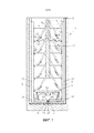
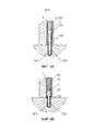
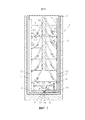
Фиг.1. Эта фигура показывает вертикальную проекцию дверного устройства согласно изобретению в неактивном положении.Figure 1. This figure shows a vertical projection of a door device according to the invention in an inactive position.
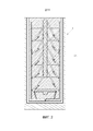
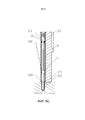
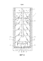
Фиг.2. Эта фигура показывает вертикальную проекцию дверного устройства согласно изобретению, показывающую основную область.Figure 2. This figure shows a vertical projection of a door device according to the invention, showing the main area.
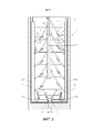
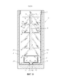
Фиг.3. Эта фигура показывает вертикальную проекцию дверного устройства согласно изобретению в промежуточном положении между неактивным положением и водонепроницаемом положении.Figure 3. This figure shows a vertical projection of a door device according to the invention in an intermediate position between an inactive position and a waterproof position.
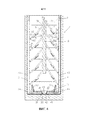
Фиг.4. Эта фигура показывает вертикальную проекцию дверного устройства согласно изобретению в водонепроницаемом положении.Figure 4. This figure shows a vertical projection of a door device according to the invention in a waterproof position.
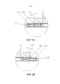
Фигуры 5а-5b. Эти фигуры показывают вид сбоку в разрезе различных деталей дверного устройства и пазовый узел согласно варианту осуществления изобретения как в неактивном, так и в водонепроницаемом положениях.Figures 5a-5b. These figures show a cross-sectional side view of various parts of a door device and a slot assembly according to an embodiment of the invention in both inactive and waterproof positions.
Фиг.5с. Эта фигура показывает вид сбоку в разрезе различных деталей дверного устройства и пазовый узел согласно варианту осуществления изобретения в неактивном положении.Figs. This figure shows a cross-sectional side view of various parts of a door device and a slot assembly according to an embodiment of the invention in an inactive position.
Фигуры 5d-5e. Эти фигуры показывают вид сверху в разрезе различных деталей дверного устройства и пазовый узел согласно варианту осуществления изобретения в неактивном положении.Figures 5d-5e. These figures show a top sectional view of various parts of a door device and a slot assembly according to an embodiment of the invention in an inactive position.
Фигуры 6а-6b. На этих фигурах показаны детали вертикальной проекции дверного устройства согласно изобретению.Figures 6a-6b. These figures show details of a vertical projection of a door device according to the invention.
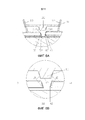
Фиг.7. Эта фигура показывает вертикальную проекцию дверного устройства согласно второму варианту осуществления изобретения в неактивном положении.7. This figure shows a vertical projection of a door device according to a second embodiment of the invention in an inactive position.
Фиг.8. Эта фигура показывает вертикальную проекцию дверного устройства согласно второму варианту осуществления изобретения в промежуточном положении между неактивным положением и водонепроницаемым положением.Fig. 8. This figure shows a vertical projection of a door device according to a second embodiment of the invention in an intermediate position between an inactive position and a waterproof position.
Фиг.9. Эта фигура показывает вертикальную проекцию дверного устройства согласно второму варианту осуществления изобретения в водонепроницаемом положении.Fig.9. This figure shows a vertical projection of a door device according to a second embodiment of the invention in a waterproof position.
ПОДРОБНОЕ ОПИСАНИЕ ИЗОБРЕТЕНИЯDETAILED DESCRIPTION OF THE INVENTION
Как только задача изобретения изложена, конкретные неограничивающие варианты осуществления описаны ниже.Once the object of the invention has been set forth, specific non-limiting embodiments are described below.
Фиг.1 показывает вертикальную проекцию дверного устройства (1) согласно изобретению в неактивном положении. Это дверное устройство (1) содержит:Figure 1 shows a vertical projection of a door device (1) according to the invention in an inactive position. This door device (1) contains:
- основную опорную поверхность (2);- the main bearing surface (2);
- основной лонжерон (10), выполненный с возможностью перемещения в направлении активации между неактивным положением и водонепроницаемым положением;- the main spar (10), configured to move in the direction of activation between the inactive position and the waterproof position;
- первый основной замыкающий элемент (3), содержащий клиновидный конец (31) с первой точкой (32) замыкания, расположенной в острой вершине упомянутого клиновидного конца (31);- the first main locking element (3) containing the wedge-shaped end (31) with the first point (32) of closure located at the sharp top of the said wedge-shaped end (31);
- второй основной замыкающий элемент (4), содержащий клиновидный конец (41) со второй точкой (42) замыкания, расположенной в острой вершине упомянутого клиновидного конца (41), при этом упомянутые первая и вторая точки (32, 42) замыкания образуют замыкающий зазор, который представляет собой расстояние между упомянутыми первой и второй точками (32, 42) замыкания;- the second main locking element (4) containing a wedge-shaped end (41) with a second closure point (42) located at the sharp top of the said wedge-shaped end (41), while the said first and second closure points (32, 42) form a closure gap which represents the distance between the first and second closure points (32, 42);
- первые соединительные элементы (5), каждый с первым концом (51) и вторым концом (52);- first connecting elements (5), each with a first end (51) and a second end (52);
- вторые соединительные элементы (6), каждый с первым концом (61) и вторым концом (62);- second connecting elements (6), each with a first end (61) and a second end (62);
- третьи соединительные элементы (7), каждый с первым концом (71) и вторым концом (72);- third connecting elements (7), each with a first end (71) and a second end (72);
- четвертые соединительные элементы (8), каждый с первым концом (81) и вторым концом (82);- fourth connecting elements (8), each with a first end (81) and a second end (82);
- первую группу первичных направляющих элементов (91) и вторую группу первичных направляющих элементов (92);- the first group of primary guide elements (91) and the second group of primary guide elements (92);
- поперечный элемент (11), содержащий вспомогательный замыкающий клин (111); и- a transverse element (11) containing an auxiliary closing wedge (111); and
- первый вторичный направляющий элемент (93), прикрепленный к первому основному замыкающему элементу (3), и второй вторичный направляющий элемент (94), прикрепленный ко второму основному замыкающему элементу (4).- a first secondary guide element (93) attached to the first main locking element (3), and a second secondary guide element (94) attached to the second main locking element (4).
Каждый первый соединительный элемент (5) шарнирно прикреплен в первом конце (51) к основному лонжерону (10), и каждый второй соединительный элемент (6) шарнирно прикреплен в первом конце (61) ко второму концу (52) одного первого соединительного элемента (5) и шарнирно прикреплен во втором конце (62) к первому основному замыкающему элементу (3).Each first connecting element (5) is pivotally attached at the first end (51) to the main spar (10), and every second connecting element (6) is pivotally attached at the first end (61) to the second end (52) of one first connecting element (5) ) and pivotally attached at the second end (62) to the first main locking element (3).
Каждый третий соединительный элемент (7) шарнирно прикреплен в первом конце (71) к основному лонжерону (10), и каждый четвертый соединительный элемент (8) шарнирно прикреплен в первом конце (81) ко второму концу (72) одного третьего соединительного элемента (7) и шарнирно прикреплен во втором конце (82) ко второму основному замыкающему элементу (4).Every third connecting element (7) is pivotally attached at the first end (71) to the main spar (10), and every fourth connecting element (8) is pivotally attached at the first end (81) to the second end (72) of one third connecting element (7) ) and pivotally attached at the second end (82) to the second main locking element (4).
Каждый первичный направляющий элемент (91, 92) прикреплен к основной опорной поверхности (2), таким образом, что каждый один из вторых соединительных элементов (6) находится в контакте с первичным направляющим элементом (91) из первой группы первичных направляющих элементов (91,) и что каждый один из четвертых соединительных элементов (8) находится в контакте с первичным направляющим элементом (92) из второй группы первичных направляющих элементов (92).Each primary guide element (91, 92) is attached to the main abutment surface (2), so that each of the second connecting elements (6) is in contact with the primary guide element (91) from the first group of primary guide elements (91, ) and that each of the fourth connecting elements (8) is in contact with the primary guide element (92) from the second group of primary guide elements (92).
Первая группа первичных направляющих элементов (91) ориентирована, образуя первый первичный направляющий угол (δ1) относительно направления (D) активации в направлении по часовой стрелке.The first group of primary guiding elements (91) is oriented, forming the first primary guiding angle (δ1) with respect to the activation direction (D) in a clockwise direction.
Вторая группа первичных направляющих элементов (92) ориентирована, образуя второй первичный направляющий угол (δ2) относительно направления (D) активации в направлении против часовой стрелки.The second group of primary guiding elements (92) is oriented, forming a second primary guiding angle (δ2) with respect to the direction of activation (D) in the counterclockwise direction.
Это приводит к тому, что система, образованная основным лонжероном (10), первыми соединительными элементами (5) и вторыми соединительными элементами (6) работает подобно кривошипно-шатунной системе: когда основной лонжерон (10) перемещается из неактивного положения в водонепроницаемое положение, первые соединительные элементы (5) передают это движение вторым соединительным элементам (6), преобразуя смещение основного лонжерона (10) согласно направлению (D) активации в смещение первого основного замыкающего элемента (3), прикрепленного ко вторым соединительным элементам (6) согласно направлению, образованному первичными направляющими элементами (91). Система, образованная основным лонжероном (10), третьими соединительными элементами (7) и четвертыми соединительными элементами (8), работает с соответствующими изменениями подобно другой кривошипно-шатунной системе.This leads to the fact that the system formed by the main spar (10), the first connecting elements (5) and the second connecting elements (6) works like a crank system: when the main spar (10) moves from an inactive position to a waterproof position, the first the connecting elements (5) transmit this movement to the second connecting elements (6), converting the displacement of the main spar (10) according to the activation direction (D) into the displacement of the first main locking element (3) attached to the second connecting elements (6) according to the direction formed primary guiding elements (91). The system formed by the main spar (10), the third connecting elements (7) and the fourth connecting elements (8) works with the corresponding changes like another crank system.
Вспомогательный замыкающий клин (111) поперечного элемента (11) содержит две стороны, образующие первый (β1) и второй (β2) углы заострения, соответственно, относительно направления (D) активации и третьей стороны, обозначенной как наземная сторона (112). Фиг.6b показывает детализированный вид вспомогательного замыкающего клина (111).The auxiliary closing wedge (111) of the transverse element (11) contains two sides forming the first (β1) and second (β2) sharpening angles, respectively, with respect to the activation direction (D) and the third side, designated as the ground side (112). 6b shows a detailed view of the auxiliary closing wedge (111).
Вторичные направляющие элементы (93, 94) выполнены с возможностью направления поперечного элемента (11). Первый вторичный направляющий элемент (93) образует первый вторичный направляющий угол (α1) относительно направления (D) активации в направлении против часовой стрелки, а второй вторичный направляющий элемент (94) образует второй вторичный направляющий угол (α2) относительно направления (D) активации в направлении по часовой стрелке.Secondary guide elements (93, 94) are configured to guide the transverse element (11). The first secondary guiding element (93) forms the first secondary guiding angle (α1) with respect to the counterclockwise direction of activation (D), and the second secondary guiding element (94) forms the second secondary guiding angle (α2) with respect to the activation direction (D) in clockwise direction.
Фиг.2 идентифицирует основную область (2а), которая соответствует области, занимаемой основной опорной поверхностью (2) дверного устройства (1).Figure 2 identifies the main area (2A), which corresponds to the area occupied by the main supporting surface (2) of the door device (1).
Фигуры 3 и 4 показывают дверное устройство (1) по фиг.1, когда основной лонжерон (10) перемещается из неактивного положения в водонепроницаемое положение. Фиг.3 показывает промежуточное положение, а фиг.4 показывает дверное устройство (1), когда главный лонжерон (10) находится в водонепроницаемом положении.Figures 3 and 4 show the door device (1) of figure 1, when the main spar (10) moves from an inactive position to a waterproof position. FIG. 3 shows an intermediate position, and FIG. 4 shows a door device (1) when the main spar (10) is in a watertight position.
В неактивном положении основного лонжерона (10), первый и второй основные замыкающие элементы (3, 4) расположены внутри основной области (2а). По ходу перемещения основного лонжерона (10) между неактивным положением и водонепроницаемым положением, перемещение каждого второго соединительного элемента (6) ограничивается соответствующим первичным направляющим элементом (91) из первой группы в направлении упомянутого первичного направляющего элемента (91), заставляя, по меньшей мере, часть первого основного замыкающего элемента (3) выходить из основной области (2а), в том смысле, что он становится не полностью содержащимся в основной области (2а). Таким же образом, перемещение каждого четвертого соединительного элемента (8) ограничивается соответствующим первичным направляющим элементом (92) из второй группы в направлении упомянутого первичного направляющего элемента (92), заставляя, по меньшей мере, часть второго основного замыкающего элемента (4) выходить из основной области (2а). Перемещение первого (3) и второго (4) основных замыкающих элементов из основной области (2а) позволяет им упираться против внешней поверхности, обеспечивая, тем самым, водонепроницаемое состояние.In the inactive position of the main spar (10), the first and second main locking elements (3, 4) are located inside the main area (2a). In the direction of movement of the main spar (10) between the inactive position and the watertight position, the movement of each second connecting element (6) is limited by the corresponding primary guide element (91) from the first group in the direction of the said primary guide element (91), forcing at least part of the first main locking element (3) to leave the main area (2a), in the sense that it becomes not completely contained in the main area (2a). In the same way, the movement of each fourth connecting element (8) is limited by the corresponding primary guide element (92) from the second group in the direction of the said primary guide element (92), causing at least a portion of the second main locking element (4) to exit the main area (2a). The movement of the first (3) and second (4) main locking elements from the main area (2a) allows them to abut against the outer surface, thereby providing a waterproof condition.
Дополнительно, вдоль упомянутого перемещения основного лонжерона (10), вторичные направляющие элементы (93, 94) направляют, по меньшей мере, часть вспомогательного замыкающего клина (111) к выходу из основной области и упора как в клиновидный конец (31) первого основного замыкающего элемента (3), так и в клиновидный конец (41) второго основного замыкающего элемента (4). Клиновидный конец (31) первого основного замыкающего элемента (3) образует замыкающий угол относительно направления (D) активации в направлении против часовой стрелки, который равен первому углу (β1) заострения. Клиновидный конец (41) второго основного замыкающего элемента (4) образует замыкающий угол относительно направления (D) активации в направлении по часовой стрелке, который равен второму углу (β2) заострения. Фиг.6b показывает детализированный вид дверного устройства согласно варианту осуществления по фигурам 1-4, на котором показаны вспомогательный замыкающий клин (111) и клиновидные концы (31, 41) первого (3) и второго (4) основных замыкающих элементов.Additionally, along the mentioned movement of the main spar (10), the secondary guiding elements (93, 94) direct at least a part of the auxiliary closing wedge (111) to the exit from the main area and the stop as to the wedge-shaped end (31) of the first main locking element (3), and in the wedge-shaped end (41) of the second main locking element (4). The wedge-shaped end (31) of the first main locking element (3) forms a closing angle with respect to the activation direction (D) in a counterclockwise direction, which is equal to the first point angle (β1). The wedge-shaped end (41) of the second main locking element (4) forms a closing angle relative to the activation direction (D) in a clockwise direction, which is equal to the second point angle (β2). Fig.6b shows a detailed view of the door device according to the embodiment of Figures 1-4, which shows the auxiliary closing wedge (111) and the wedge-shaped ends (31, 41) of the first (3) and second (4) main locking elements.
Когда основные замыкающие элементы (3, 4) перемещаются к водонепроницаемому положению, замыкающий зазор увеличивается, поскольку основные замыкающие элементы (3, 4) перемещаются в разных направлениях. Один из основных замыкающих элементов (3) перемещается в направлении первой группы первичных направляющих элементов (91), а другой основной замыкающий элемент (4) перемещается в направлении второй группы первичных направляющих элементов (92).When the main locking elements (3, 4) move to a watertight position, the closing gap increases because the main locking elements (3, 4) move in different directions. One of the main locking elements (3) moves in the direction of the first group of primary guide elements (91), and the other main locking element (4) moves in the direction of the second group of primary guide elements (92).
Вторичные направляющие элементы (93, 94) выполнены с возможностью направления поперечного элемента (11). Это направление отличается от направления, обеспечиваемого первичными направляющими элементами (91, 92). В случае этого конкретного варианта осуществления, один вторичный направляющий элемент (93, 94) прикреплен к каждому основному замыкающему элементу (3, 4). Когда основные замыкающие элементы (3, 4) перемещаются, вторичные направляющие элементы (93, 94) перемещаются вместе с ними, и замыкающий зазор увеличивается. Поскольку поперечный элемент (11) имеет постоянную длину, он скользит вдоль вторичных направляющих элементов (93, 94), пока часть его расположится в зазоре между первым и вторым основными замыкающими элементами (3, 4).Secondary guide elements (93, 94) are configured to guide the transverse element (11). This direction differs from the direction provided by the primary guiding elements (91, 92). In the case of this particular embodiment, one secondary guiding element (93, 94) is attached to each main locking element (3, 4). When the main locking elements (3, 4) move, the secondary guiding elements (93, 94) move with them, and the closing gap increases. Since the transverse element (11) has a constant length, it slides along the secondary guide elements (93, 94), while part of it is located in the gap between the first and second main locking elements (3, 4).
Для достижения без зазорного расположения между первым и вторым основными замыкающими элементами (3, 4) и вспомогательным замыкающим клином (111), когда основной лонжерон (10) находится в водонепроницаемом положении, замыкающий зазор равен длине наземной стороны (112) вспомогательного замыкающего клина (111). Дополнительно, чтобы сделать возможным перемещение поперечного элемента (11), первый вторичный направляющий угол (α1) меньше или равен, чем первый угол заострения (β1), а второй вторичный направляющий угол (α2) меньше или равен, чем второй угол заострения (β2).To achieve without a gap between the first and second main locking elements (3, 4) and the auxiliary closing wedge (111), when the main spar (10) is in a waterproof position, the closing gap is equal to the length of the ground side (112) of the auxiliary closing wedge (111 ) Additionally, in order to enable movement of the transverse member (11), the first secondary guide angle (α1) is less than or equal to the first taper angle (β1), and the second secondary guide angle (α2) is less than or equal to the second taper angle (β2) .
Как первый, так и второй основные замыкающие элементы (3, 4) являются, по существу, L-образными в этом варианте осуществления, каждый из которых содержит более длинное плечо (33, 43) и более короткое плечо (34, 44); более длинные плечи (33, 43) расположены, по существу, параллельно друг другу, а более короткие плечи (34, 44) направлены друг к другу.Both the first and second main locking elements (3, 4) are essentially L-shaped in this embodiment, each of which contains a longer shoulder (33, 43) and a shorter shoulder (34, 44); longer shoulders (33, 43) are arranged essentially parallel to each other, and shorter shoulders (34, 44) are directed towards each other.
В этом варианте осуществления, первый и второй основные замыкающие элементы (3, 4) размещены так, что, когда основной лонжерон (10) находится в неактивном положении, более длинные плечи (33, 43) и более короткие плечи (34, 44) расположены по краям основной области, которая в этом варианте осуществления является прямоугольной.In this embodiment, the first and second main locking elements (3, 4) are arranged such that when the main spar (10) is in an inactive position, longer shoulders (33, 43) and shorter shoulders (34, 44) are located along the edges of the main region, which in this embodiment is rectangular.
Фиг.5а показывает детализированный вид сбоку дверного устройства согласно изобретению, расположенного на двери, вместе с видом сбоку пазового узла согласно изобретению, когда основной лонжерон (не показан на этой фигуре) находится в неактивном положении. В этом варианте осуществления дверного устройства, первый и второй основные замыкающие элементы (3, 4), по существу, являются L-образными, и каждый из них содержит более длинное плечо (33, 43) и более короткое плечо (34, 44), как в варианте осуществления с 1 по 4. Пазовый узел содержит первый паз (121), выполненный с возможностью приема, по меньшей мере, части более длинного плеча (33) первого основного замыкающего элемента (3), и второй паз (122), выполненный с возможностью приема, по меньшей мере, части более длинного плеча (43) второго основного замыкающего элемента, и третий паз (123), выполненный с возможностью приема, по меньшей мере, части более короткого плеча (34) первого основного замыкающего элемента (3), по меньшей мере, части более короткого плеча (44) второго основного замыкающего элемента (4) и, по меньшей мере, части вспомогательного замыкающего клина (111), когда основной лонжерон находится в неактивном положении.Fig. 5a shows a detailed side view of a door device according to the invention located on a door, together with a side view of a groove assembly according to the invention, when the main spar (not shown in this figure) is in an inactive position. In this embodiment of the door device, the first and second main locking elements (3, 4) are essentially L-shaped, and each of them contains a longer arm (33, 43) and a shorter arm (34, 44), as in
В этом варианте осуществления, дверное устройство дополнительно содержит вторичную опорную поверхность (21), расположенную параллельно основной опорной поверхности (2). Первый основной замыкающий элемент (3) можно видеть расположенным между основной опорной поверхностью (2) и вторичной опорной поверхностью (21). Основная опорная поверхность (2) прикреплена к поверхности двери.In this embodiment, the door device further comprises a secondary abutment surface (21) located parallel to the main abutment surface (2). The first main locking element (3) can be seen located between the main abutment surface (2) and the secondary abutment surface (21). The main supporting surface (2) is attached to the surface of the door.
На фиг.5а показано короткое плечо первого основного замыкающего элемента (3) и третий пазовый узел (123). Можно заметить, как первый основной замыкающий элемент (3) содержит первые уплотнительные элементы (101). Основная опорная поверхность (2) и вторичная опорная поверхность (21) дополнительно содержат вторые уплотнительные элементы (102). Первый и второй уплотнительные элементы (101, 102) выполнены с возможностью взаимодействия друг с другом, когда основной лонжерон (не показан на этой фигуре) находится в водонепроницаемом положении, обеспечивая, таким образом, уплотняющее зацепление между первым основным замыкающим элементом (3) и основной (2) и вторичной (21) опорными поверхностями.Fig. 5a shows the short arm of the first main locking element (3) and the third groove assembly (123). You can see how the first main locking element (3) contains the first sealing elements (101). The main abutment surface (2) and the secondary abutment surface (21) further comprise second sealing elements (102). The first and second sealing elements (101, 102) are arranged to interact with each other when the main spar (not shown in this figure) is in a watertight position, thus providing sealing engagement between the first main locking element (3) and the main (2) and secondary (21) abutment surfaces.
Дополнительно, третий паз (123) пазового узла содержит третьи уплотнительные элементы (103), выполненные с возможностью взаимодействия с первым основным замыкающим элементом (3), обеспечивая водонепроницаемое уплотнение, когда основной лонжерон (не показан на этой фигуре) находится в водонепроницаемое положение.Additionally, the third groove (123) of the groove assembly includes third sealing elements (103) configured to interact with the first main locking element (3), providing a waterproof seal when the main spar (not shown in this figure) is in a waterproof position.
В одном варианте осуществления, первые уплотнительные элементы (101) расположены вдоль зон основных замыкающих элементов (3, 4) и вспомогательного замыкающего клина (111), которые предназначены для контакта с основной (2) и/или вторичной (21) опорной поверхностью, когда основной лонжерон (10) находится в водонепроницаемом положении. В свою очередь, вторые уплотнительные элементы (102) расположены вдоль зон основной (2) и/или вторичной (21) опорной поверхности, где первые уплотнительные элементы (101) предназначены для контакта.In one embodiment, the first sealing elements (101) are located along the zones of the main locking elements (3, 4) and the auxiliary closing wedge (111), which are designed to contact the main (2) and / or secondary (21) abutment surface when the main spar (10) is in a waterproof position. In turn, the second sealing elements (102) are located along the zones of the main (2) and / or secondary (21) supporting surface, where the first sealing elements (101) are intended for contact.
Фиг.5b показывает элементы по фиг.5a, но когда основной лонжерон (10) находится в водонепроницаемом положении. Как и на этой фигуре, первый основной замыкающий элемент (3) находится внутри третьего паза, этот третий паз не виден. На фиг.5b первые уплотнительные элементы (101) примыкают ко вторым уплотнительным элементам (102). Первый и второй уплотнительные элементы (101, 102) изображены черными на этой фигуре.Fig. 5b shows the elements of Fig. 5a, but when the main spar (10) is in a waterproof position. As in this figure, the first main locking element (3) is located inside the third groove, this third groove is not visible. 5b, the first sealing elements (101) are adjacent to the second sealing elements (102). The first and second sealing elements (101, 102) are shown in black in this figure.
В вариантах осуществления, описанных выше, основной лонжерон (10), основные замыкающие элементы (3, 4), первые соединительные элементы (5), вторые соединительные элементы (6), третьи соединительные элементы (7), четвертые соединительные элементы (8), поперечный элемент (11) и вторичные направляющие элементы (93, 94) механически взаимосвязаны, движение одного из них вызывает перемещение остальных частей: хотя перемещение основного лонжерона (10) является наиболее распространенным способом инициирования перемещения дверного устройства (1) из неактивного положения в водонепроницаемое положение, можно инициировать перемещение путем воздействия или на основные замыкающие элементы (3, 4), или соединительные элементы (5, 6, 7, 8), или поперечный элемент (11). Дополнительно, движение всех этих элементов является обратимым, т.е., когда основной лонжерон (10) возвращается назад от водонепроницаемого положения к неактивному положению, остальные части также возвращаются в их неактивные положения.In the embodiments described above, the main spar (10), the main locking elements (3, 4), the first connecting elements (5), the second connecting elements (6), the third connecting elements (7), the fourth connecting elements (8), the transverse element (11) and the secondary guide elements (93, 94) are mechanically interconnected, the movement of one of them causes the rest of the parts to move: although moving the main spar (10) is the most common way to initiate the movement of the door device (1) from an inactive position to a waterproof position , you can initiate movement by acting on either the main locking elements (3, 4), or the connecting elements (5, 6, 7, 8), or the transverse element (11). Additionally, the movement of all these elements is reversible, i.e., when the main spar (10) moves back from the waterproof position to the inactive position, the remaining parts also return to their inactive positions.
Фиг.5c показывает вид, аналогичный виду на фиг.5а. В этом случае показаны второй основной замыкающий элемент (4) и вспомогательный замыкающий клин (111), которые представляют собой аналогичную конфигурацию, с первыми уплотнительными элементами (101). Второе уплотнительное средство (102) основной (2) и вторичной (21) опорной поверхности также взаимодействует с первыми уплотнительными элементами (101) второго основного замыкающего элемента (4) и вспомогательного замыкающего клина (111). Дополнительно, третий паз (123), подходящий для приема более короткого плеча каждого из основных замыкающих элементов (3, 4) и вспомогательного замыкающего клина (111), также содержит третьи уплотнительные элементы (103), выполненные с возможностью взаимодействия с более коротким плечом каждого из основных замыкающих элементов (3, 4) и вспомогательным замыкающим клином (111).Fig. 5c shows a view similar to that in Fig. 5a. In this case, a second main closure element (4) and an auxiliary closure wedge (111) are shown, which represent a similar configuration, with the first sealing elements (101). The second sealing means (102) of the primary (2) and secondary (21) abutment surfaces also interacts with the first sealing elements (101) of the second main closure element (4) and the auxiliary closure wedge (111). Additionally, the third groove (123), suitable for receiving a shorter shoulder of each of the main locking elements (3, 4) and the auxiliary closing wedge (111), also contains third sealing elements (103), configured to interact with the shorter shoulder of each of the main locking elements (3, 4) and the auxiliary closing wedge (111).
Как упоминалось выше, на этих фигурах 5а-5с также показана вторичная опорная поверхность (21), содержащая вторые уплотнительные элементы (102) так же, как и основная опорная поверхность (2). В других вариантах осуществления, дверное устройство включает в себя только основную опорную поверхность, а сама дверь, к которой прикреплено дверное устройство (1), используется как вторичная опорная поверхность. В вариантах осуществления, показанных на фигурах 5а-5с, также присутствует вспомогательная крышка (20), покрывающая видимую сторону дверного устройства для декоративных целей.As mentioned above, these figures 5a-5c also show a secondary abutment surface (21) containing second sealing elements (102) in the same way as the main abutment surface (2). In other embodiments, the door device includes only the main supporting surface, and the door itself to which the door device (1) is attached is used as the secondary supporting surface. In the embodiments shown in Figures 5a-5c, there is also an auxiliary cover (20) covering the visible side of the door device for decorative purposes.
На фигурах 5d и 5e показан вид сбоку более длинных плеч основных замыкающих элементов (3, 4) варианта осуществления изобретения в их неактивных положениях, а также первый (121) и второй (122) пазы пазового узла, выполненные с возможностью приема, по меньшей мере, частично основных замыкающих элементов (3, 4).Figures 5d and 5e show a side view of the longer shoulders of the main locking elements (3, 4) of an embodiment of the invention in their inactive positions, as well as the first (121) and second (122) grooves of the slot assembly configured to receive at least , partially of the main closing elements (3, 4).
Фиг.5d показывает более длинное плечо первого основного замыкающего элемента (3), содержащее первые уплотнительные элементы (101). Основная опорная поверхность (2) дополнительно содержит второй уплотнительный элемент (102). Первый и второй уплотнительные элементы (101, 102) выполнены с возможностью взаимодействия друг с другом, когда основной лонжерон (не показан на этой фигуре) находится в водонепроницаемом положении, обеспечивая, таким образом, уплотняющее зацепление между первым основным замыкающим элементом (3) и основной опорной поверхностью.Fig. 5d shows a longer shoulder of the first main locking element (3) containing the first sealing elements (101). The main supporting surface (2) further comprises a second sealing element (102). The first and second sealing elements (101, 102) are arranged to interact with each other when the main spar (not shown in this figure) is in a watertight position, thus providing sealing engagement between the first main locking element (3) and the main supporting surface.
Дополнительно, первый паз (121) пазового узла содержит третьи уплотнительные элементы (103), выполненные с возможностью взаимодействия с первым основным замыкающим элементом (3), обеспечивающие водонепроницаемое уплотнение, когда основной лонжерон (не показан на этой фигуре) находится в водонепроницаемое положение.Additionally, the first groove (121) of the groove assembly comprises third sealing elements (103) configured to interact with the first main locking element (3), providing a waterproof seal when the main spar (not shown in this figure) is in a waterproof position.
Фиг.5е показывает более длинное плечо второго основного замыкающего элемента (4), содержащее первые уплотнительные элементы (101). Основная опорная поверхность дополнительно содержит второй уплотнительный элемент (102). Первый и второй уплотнительные элементы (101, 102) выполнены с возможностью взаимодействия друг с другом, когда основной лонжерон (не показан на этой фигуре) находится в водонепроницаемом положении, обеспечивая, таким образом, уплотняющее зацепление между первым основным замыкающим элементом (3) и основной опорной поверхностью.Fig. 5e shows a longer shoulder of the second main locking element (4) containing the first sealing elements (101). The main supporting surface further comprises a second sealing element (102). The first and second sealing elements (101, 102) are arranged to interact with each other when the main spar (not shown in this figure) is in a watertight position, thus providing sealing engagement between the first main locking element (3) and the main supporting surface.
Дополнительно, второй паз (122) пазового узла содержит третьи уплотнительные элементы (103), выполненные с возможностью взаимодействия со вторым основным замыкающим элементом (4), обеспечивающие водонепроницаемое уплотнение, когда основной лонжерон (не показан на этой фигуре) находится в водонепроницаемом положении.Additionally, the second groove (122) of the groove assembly comprises third sealing elements (103) configured to interact with the second main locking element (4), providing a waterproof seal when the main spar (not shown in this figure) is in a waterproof position.
Фиг.6а показывает другую детализацию дверного устройства (1) согласно варианту осуществления изобретения. На этой фигуре показаны четвертые уплотнительные средства (104), содержащиеся на клиновидных концах (31, 41) первого и второго основных замыкающих элементов (3, 4), и на вспомогательном замыкающем клине (111). Эти четвертые уплотнительные средства (104) предназначены для взаимодействия между ними, когда основной лонжерон (10) находится в водонепроницаемом положении.6a shows another detail of a door device (1) according to an embodiment of the invention. This figure shows the fourth sealing means (104) contained on the tapered ends (31, 41) of the first and second main locking elements (3, 4), and on the auxiliary locking wedge (111). These fourth sealing means (104) are designed to interact between them when the main spar (10) is in a waterproof position.
В одном варианте осуществления, все уплотнительные элементы (101, 102, 103, 104) выполнены из упругого материала, такого как резина, так что они могут быть прижаты друг к другу, деформируясь, таким образом, и обеспечивая упомянутое водонепроницаемое уплотнение.In one embodiment, all of the sealing elements (101, 102, 103, 104) are made of an elastic material, such as rubber, so that they can be pressed against each other, thereby deforming, and providing said waterproof seal.
Фиг.7 показывает другой вариант осуществления дверного устройства (1) согласно изобретению. В этом варианте осуществления, вторичные направляющие элементы (93, 94) прикреплены к основной опорной поверхности (2), а первый и второй вторичные направляющие углы (α1, α2) равны нулю. В этом случае, перемещение основных замыкающих элементов (3, 4) не вызывает перемещения в поперечном элементе (11), а поперечный элемент (11) перемещается когда основной лонжерон (10) находится в своем водонепроницаемом положении.7 shows another embodiment of a door device (1) according to the invention. In this embodiment, the secondary guide elements (93, 94) are attached to the main supporting surface (2), and the first and second secondary guide angles (α1, α2) are equal to zero. In this case, the movement of the main locking elements (3, 4) does not cause movement in the transverse element (11), and the transverse element (11) moves when the main spar (10) is in its waterproof position.
В этом варианте осуществления, поскольку упомянутые перемещения не связаны, дверное устройство (1) дополнительно содержит первый управляющий элемент (не показан), выполненный с возможностью перемещения поперечного элемента (11) в положение, в котором вспомогательный замыкающий клин (111) упирается как в клиновидный конец первого основного замыкающего элемента (3), так и в клиновидный конец второго основного замыкающего элемента (4).In this embodiment, since the said movements are not connected, the door device (1) further comprises a first control element (not shown) configured to move the transverse element (11) to a position in which the auxiliary closing wedge (111) abuts like a wedge-shaped the end of the first main locking element (3), and in the wedge-shaped end of the second main locking element (4).
Фиг.8 показывает этот вариант осуществления дверного устройства (1) в положении, которое является промежуточным между неактивным положением и водонепроницаемым положением. В промежуточном положении, показанном на фиг.8, первый основной замыкающий элемент (3) и второй основной замыкающий элемент (4) помещаются в их окончательные водонепроницаемые положения, в то время как поперечный элемент (11) все еще находится в неактивном положении.Fig. 8 shows this embodiment of a door device (1) in a position that is intermediate between an inactive position and a waterproof position. In the intermediate position shown in Fig. 8, the first main closure element (3) and the second main closure element (4) are placed in their final watertight position, while the transverse element (11) is still in the inactive position.
Фиг.9, в свою очередь, показывает этот вариант осуществления дверного устройства (1) в водонепроницаемом положении, в котором поперечный элемент (11) находится в своем водонепроницаемом положении, а вспомогательный клин (111) располагается между клиновидным концом первого основного замыкающего элемента (3) и клиновидным концом второго основного замыкающего элемента (4), которые также находятся в их водонепроницаемых положениях. Fig. 9, in turn, shows this embodiment of the door device (1) in a watertight position in which the transverse element (11) is in its watertight position and the auxiliary wedge (111) is located between the wedge-shaped end of the first main locking element (3 ) and the wedge-shaped end of the second main locking element (4), which are also in their watertight positions.
Claims (35)
Applications Claiming Priority (3)
| Application Number | Priority Date | Filing Date | Title |
|---|---|---|---|
| EP16382024.4A EP3196391A1 (en) | 2016-01-21 | 2016-01-21 | Door device |
| EP16382024.4 | 2016-01-21 | ||
| PCT/EP2017/051165 WO2017125537A1 (en) | 2016-01-21 | 2017-01-20 | Door device |
Publications (3)
| Publication Number | Publication Date |
|---|---|
| RU2018130100A RU2018130100A (en) | 2020-02-21 |
| RU2018130100A3 RU2018130100A3 (en) | 2020-03-20 |
| RU2721038C2 true RU2721038C2 (en) | 2020-05-15 |
Family
ID=55262769
Family Applications (1)
| Application Number | Title | Priority Date | Filing Date |
|---|---|---|---|
| RU2018130100A RU2721038C2 (en) | 2016-01-21 | 2017-01-20 | Door device |
Country Status (9)
| Country | Link |
|---|---|
| US (1) | US10590684B2 (en) |
| EP (2) | EP3196391A1 (en) |
| JP (1) | JP6786626B2 (en) |
| AU (1) | AU2017208558B2 (en) |
| CA (1) | CA3012035A1 (en) |
| ES (1) | ES2770369T3 (en) |
| PT (1) | PT3405635T (en) |
| RU (1) | RU2721038C2 (en) |
| WO (1) | WO2017125537A1 (en) |
Families Citing this family (3)
| Publication number | Priority date | Publication date | Assignee | Title |
|---|---|---|---|---|
| US11198499B2 (en) * | 2019-09-05 | 2021-12-14 | Rolls-Royce North American Technologies Inc. | Adjustable door seal |
| DE102019126666B4 (en) * | 2019-10-02 | 2022-06-09 | Honerkamp Industrievertriebs GmbH | Device for protection against flooding and a door or window with such a device |
| CN112696134B (en) * | 2020-12-24 | 2022-03-25 | 南通理工学院 | Flood control device |
Citations (5)
| Publication number | Priority date | Publication date | Assignee | Title |
|---|---|---|---|---|
| US595128A (en) * | 1897-12-07 | Refrigerator-do or | ||
| GB846642A (en) * | 1958-03-20 | 1960-08-31 | Bolt Beranek & Newman | Apparatus for closure sealing |
| SU1471951A3 (en) * | 1983-05-27 | 1989-04-07 | Ой Вяртисиля Аб (Фирма) | Door arrangement |
| EP0388334A1 (en) * | 1989-03-14 | 1990-09-19 | Etablissements Jean Etudes Et Realisation Metalliques Sarl | Closure, especially door, with peripheral bolts |
| RU1813162C (en) * | 1991-04-12 | 1993-04-30 | Центральный Научно-Исследовательский, Проектный И Конструкторско-Технологический Институт Легких Металлических Конструкций "Цниипроектлегконструкция" | Protecting door |
Family Cites Families (18)
| Publication number | Priority date | Publication date | Assignee | Title |
|---|---|---|---|---|
| US473800A (en) * | 1892-04-26 | Wilhelm johann van broek | ||
| US1345967A (en) * | 1917-09-29 | 1920-07-06 | Smelser Jess | Door |
| US2295324A (en) * | 1939-03-18 | 1942-09-08 | Charles E Arthur | Closure actuating and locking mechanism |
| US2500000A (en) * | 1945-12-05 | 1950-03-07 | Heintz Mfg Co | Interlock for quick fastening doors |
| US3059287A (en) * | 1958-03-20 | 1962-10-23 | Bolt Beranek & Newman | Apparatus for and method of soundproof closure sealing |
| US4180943A (en) * | 1978-09-15 | 1980-01-01 | Mcdonnell Douglas Corporation | Dual lost motion mechanism for an aircraft door |
| US4534192A (en) * | 1983-01-19 | 1985-08-13 | Jgr Enterprises, Inc. | Security door |
| US4754715A (en) * | 1984-12-10 | 1988-07-05 | Squires William D | Toggle-type safe door locking mechanism |
| DE69200833T2 (en) * | 1992-01-21 | 1995-06-01 | Winel Machinefab Handel | Door leaf for closing an opening and locking system for use as part of it. |
| FR2770251B1 (en) * | 1997-10-27 | 1999-12-17 | Ind Du Ponant L | PIVOTING DOOR OF THE TYPE COMPRISING AT LEAST ONE LEAF ON WHICH ARE MOUNTED PARALLEL TWO RODS VIA CONNECTING RODS |
| US6105313A (en) * | 1999-01-11 | 2000-08-22 | Holloway; Max M. | Handicap door with edge seals |
| US6446393B1 (en) * | 2000-05-12 | 2002-09-10 | Bath Iron Works Corporation | Watertight door apparatus |
| US7707773B2 (en) * | 2005-12-30 | 2010-05-04 | Speyer Door And Window, Inc. | Seal activation system positioned within panel for door/window |
| GB0710395D0 (en) * | 2007-06-01 | 2007-07-11 | Cedardell Ltd | Security assembly and method of controlling a security assembley |
| TWI365030B (en) * | 2009-06-25 | 2012-05-21 | Wistron Corp | Covering mechanism for covering an opening of a housing |
| US8276527B2 (en) * | 2009-10-08 | 2012-10-02 | Prosteel Security Products, Inc. | Corner bolt locking system |
| US8347665B2 (en) * | 2010-01-18 | 2013-01-08 | Liberty Safe And Security Products, Inc. | Self-balancing locking mechanism for doors |
| US9540843B2 (en) * | 2014-08-27 | 2017-01-10 | Shade River Outfitters, Inc. | Lock pin and bolt construction for securing doors and other closures |
-
2016
- 2016-01-21 EP EP16382024.4A patent/EP3196391A1/en not_active Withdrawn
-
2017
- 2017-01-20 US US16/071,689 patent/US10590684B2/en active Active
- 2017-01-20 EP EP17700702.8A patent/EP3405635B1/en active Active
- 2017-01-20 PT PT177007028T patent/PT3405635T/en unknown
- 2017-01-20 AU AU2017208558A patent/AU2017208558B2/en active Active
- 2017-01-20 WO PCT/EP2017/051165 patent/WO2017125537A1/en active Application Filing
- 2017-01-20 ES ES17700702T patent/ES2770369T3/en active Active
- 2017-01-20 CA CA3012035A patent/CA3012035A1/en active Pending
- 2017-01-20 JP JP2018557199A patent/JP6786626B2/en active Active
- 2017-01-20 RU RU2018130100A patent/RU2721038C2/en active
Patent Citations (5)
| Publication number | Priority date | Publication date | Assignee | Title |
|---|---|---|---|---|
| US595128A (en) * | 1897-12-07 | Refrigerator-do or | ||
| GB846642A (en) * | 1958-03-20 | 1960-08-31 | Bolt Beranek & Newman | Apparatus for closure sealing |
| SU1471951A3 (en) * | 1983-05-27 | 1989-04-07 | Ой Вяртисиля Аб (Фирма) | Door arrangement |
| EP0388334A1 (en) * | 1989-03-14 | 1990-09-19 | Etablissements Jean Etudes Et Realisation Metalliques Sarl | Closure, especially door, with peripheral bolts |
| RU1813162C (en) * | 1991-04-12 | 1993-04-30 | Центральный Научно-Исследовательский, Проектный И Конструкторско-Технологический Институт Легких Металлических Конструкций "Цниипроектлегконструкция" | Protecting door |
Also Published As
| Publication number | Publication date |
|---|---|
| JP6786626B2 (en) | 2020-11-18 |
| ES2770369T3 (en) | 2020-07-01 |
| EP3405635B1 (en) | 2019-11-27 |
| AU2017208558A1 (en) | 2018-08-16 |
| AU2017208558B2 (en) | 2021-08-05 |
| EP3196391A1 (en) | 2017-07-26 |
| PT3405635T (en) | 2020-01-22 |
| US20190032379A1 (en) | 2019-01-31 |
| RU2018130100A (en) | 2020-02-21 |
| US10590684B2 (en) | 2020-03-17 |
| WO2017125537A1 (en) | 2017-07-27 |
| JP2019508613A (en) | 2019-03-28 |
| EP3405635A1 (en) | 2018-11-28 |
| RU2018130100A3 (en) | 2020-03-20 |
| CA3012035A1 (en) | 2017-07-27 |
Similar Documents
| Publication | Publication Date | Title |
|---|---|---|
| RU2721038C2 (en) | Door device | |
| RU2015140621A (en) | PROFILED ELEMENT FOR CONNECTING THE GLASS OF THE VEHICLE WITH THE COVER DETAIL AND ASSEMBLY OF THE PROFILED ELEMENT | |
| EP3369870A1 (en) | Expansion joint | |
| DE102015100007B4 (en) | End seal for a vehicle | |
| KR101691962B1 (en) | Coaming assembly | |
| JP2019508613A5 (en) | ||
| DE10023415C2 (en) | Panel mounting structure for vehicles | |
| JPH0635786B2 (en) | Sash mounting structure | |
| DE2531695C3 (en) | Device for bridging the joint between two parts of a roof covering | |
| DE102015218374A1 (en) | Installation tool for an insert in a linear guide rail | |
| CN216657955U (en) | Robot head mechanism | |
| ITUB20154888A1 (en) | SOLUTION FOR MUTUAL FIXING OF COMPONENT PARTS OF A CLOSING SYSTEM, IN PARTICULAR FOR JOINERY | |
| JP6908490B2 (en) | Joinery | |
| JP2016053243A (en) | Impervious plate and waterproof device of opening | |
| RU2736573C1 (en) | Wedge mechanism | |
| RU175699U1 (en) | Skirting board | |
| EP3497293B1 (en) | Hinge system | |
| RU2072945C1 (en) | Hinge fitting of extensible aerodynamic surface | |
| JP6689129B2 (en) | Ruler edge | |
| CN203050047U (en) | Arranging construction of waterproof boards | |
| CN105952295A (en) | Push-pull device of architectural ornament sliding door | |
| DE202005012421U1 (en) | Roof screen for motor vehicle, especially side roof screen, has inner body of plastic fastened to body of vehicle, and outer shell of plastic connected to inner body by at least one adhesive surface | |
| TR2022001243U5 (en) | Wheel System for Sliding Glass Doors in Shower Enclosures | |
| KR101607685B1 (en) | Module bridge device | |
| RU2549321C1 (en) | Door |