RU2717726C2 - Heat exchanger - Google Patents
Heat exchanger Download PDFInfo
- Publication number
- RU2717726C2 RU2717726C2 RU2018128046A RU2018128046A RU2717726C2 RU 2717726 C2 RU2717726 C2 RU 2717726C2 RU 2018128046 A RU2018128046 A RU 2018128046A RU 2018128046 A RU2018128046 A RU 2018128046A RU 2717726 C2 RU2717726 C2 RU 2717726C2
- Authority
- RU
- Russia
- Prior art keywords
- heat exchanger
- specified
- matrix
- heat
- modular
- Prior art date
Links
Images

Classifications
-
- F—MECHANICAL ENGINEERING; LIGHTING; HEATING; WEAPONS; BLASTING
- F28—HEAT EXCHANGE IN GENERAL
- F28D—HEAT-EXCHANGE APPARATUS, NOT PROVIDED FOR IN ANOTHER SUBCLASS, IN WHICH THE HEAT-EXCHANGE MEDIA DO NOT COME INTO DIRECT CONTACT
- F28D7/00—Heat-exchange apparatus having stationary tubular conduit assemblies for both heat-exchange media, the media being in contact with different sides of a conduit wall
- F28D7/0008—Heat-exchange apparatus having stationary tubular conduit assemblies for both heat-exchange media, the media being in contact with different sides of a conduit wall the conduits for one medium being in heat conductive contact with the conduits for the other medium
- F28D7/0025—Heat-exchange apparatus having stationary tubular conduit assemblies for both heat-exchange media, the media being in contact with different sides of a conduit wall the conduits for one medium being in heat conductive contact with the conduits for the other medium the conduits for one medium or the conduits for both media being flat tubes or arrays of tubes
-
- F—MECHANICAL ENGINEERING; LIGHTING; HEATING; WEAPONS; BLASTING
- F28—HEAT EXCHANGE IN GENERAL
- F28F—DETAILS OF HEAT-EXCHANGE AND HEAT-TRANSFER APPARATUS, OF GENERAL APPLICATION
- F28F7/00—Elements not covered by group F28F1/00, F28F3/00 or F28F5/00
- F28F7/02—Blocks traversed by passages for heat-exchange media
-
- F—MECHANICAL ENGINEERING; LIGHTING; HEATING; WEAPONS; BLASTING
- F28—HEAT EXCHANGE IN GENERAL
- F28F—DETAILS OF HEAT-EXCHANGE AND HEAT-TRANSFER APPARATUS, OF GENERAL APPLICATION
- F28F13/00—Arrangements for modifying heat-transfer, e.g. increasing, decreasing
- F28F2013/005—Thermal joints
- F28F2013/006—Heat conductive materials
-
- F—MECHANICAL ENGINEERING; LIGHTING; HEATING; WEAPONS; BLASTING
- F28—HEAT EXCHANGE IN GENERAL
- F28F—DETAILS OF HEAT-EXCHANGE AND HEAT-TRANSFER APPARATUS, OF GENERAL APPLICATION
- F28F2265/00—Safety or protection arrangements; Arrangements for preventing malfunction
- F28F2265/26—Safety or protection arrangements; Arrangements for preventing malfunction for allowing differential expansion between elements
-
- F—MECHANICAL ENGINEERING; LIGHTING; HEATING; WEAPONS; BLASTING
- F28—HEAT EXCHANGE IN GENERAL
- F28F—DETAILS OF HEAT-EXCHANGE AND HEAT-TRANSFER APPARATUS, OF GENERAL APPLICATION
- F28F2270/00—Thermal insulation; Thermal decoupling
-
- F—MECHANICAL ENGINEERING; LIGHTING; HEATING; WEAPONS; BLASTING
- F28—HEAT EXCHANGE IN GENERAL
- F28F—DETAILS OF HEAT-EXCHANGE AND HEAT-TRANSFER APPARATUS, OF GENERAL APPLICATION
- F28F2275/00—Fastening; Joining
- F28F2275/20—Fastening; Joining with threaded elements
Abstract
Description
Область техники, к которой относится изобретениеFIELD OF THE INVENTION
Настоящее изобретение относится к теплообменникам. В частности, изобретение разработано применительно к теплообменникам для текучих сред, находящихся при высоких температуре и давлении и содержащих агрессивные химические вещества (например, токсичные и/или коррозионные компоненты).The present invention relates to heat exchangers. In particular, the invention has been developed for heat exchangers for fluids at high temperature and pressure and containing aggressive chemicals (for example, toxic and / or corrosive components).
Уровень техники и общая техническая проблемаBACKGROUND AND GENERAL TECHNICAL PROBLEM
Текучие среды, находящиеся при высоких температуре и давлении и, возможно, содержащие агрессивные химические вещества, требуют применения теплообменников с существенно специализированной конструкцией, как правило, на основе так называемой двухтрубной технологии.Fluids located at high temperature and pressure and possibly containing aggressive chemicals require the use of heat exchangers with a substantially specialized design, usually based on the so-called two-pipe technology.
Эта технология предусматривает изготовление теплообменников с парой трубчатых элементов, один из которых находится внутри другого, по которым идут потоки горячей и холодной текучих сред. Однако, как правило, эта технология требует огромных экономических ресурсов для производства и монтажа такого теплообменника, а также очень сложных технологических решений для компенсации разного теплового расширения в осевом направлении у внутренней и наружной трубок, по которым двигаются текучие среды.This technology involves the manufacture of heat exchangers with a pair of tubular elements, one of which is inside the other, through which flows of hot and cold fluids. However, as a rule, this technology requires enormous economic resources for the production and installation of such a heat exchanger, as well as very complex technological solutions to compensate for different thermal expansion in the axial direction of the inner and outer tubes along which the fluids move.
Это влечет за собой необходимость, в случае традиционных двухтрубных теплообменников или трубчатых теплообменников, работающих с высокотемпературными текучими средами, создания компенсационных швов для подсоединения внутренних и наружных трубок к трубам, подающим текучие среды в теплообменник, или же использования дорогостоящих и сложных плавающих головок.This entails the need, in the case of traditional double-tube heat exchangers or tubular heat exchangers working with high-temperature fluids, to create expansion joints for connecting the inner and outer tubes to the pipes supplying fluids to the heat exchanger, or to use expensive and complex floating heads.
Следует отметить, что теплообменник должен быть изготовлен из материалов, которые способны выдерживать чрезвычайно высокие конструктивные напряжения (тепловые и механические) и одновременно сильные химические воздействия (коррозия и охрупчивание).It should be noted that the heat exchanger must be made of materials that can withstand extremely high structural stresses (thermal and mechanical) and at the same time strong chemical influences (corrosion and embrittlement).
По этим причинам производство этих устройств является непростым и даже экономически нецелесообразным, поскольку одно только обеспечение прочности конструкции требует очень большой толщины стенок, что значительно увеличивает стоимость материала, так как необходимо использовать высокопрочные стали.For these reasons, the production of these devices is difficult and even not economically feasible, since the mere provision of structural strength requires a very large wall thickness, which significantly increases the cost of the material, since it is necessary to use high-strength steels.
В любом случае, теплообменник имеет исключительно высокую себестоимость из-за необходимости использования высокопрочных сплавов, таких как сталь Inconel 825 или AISI 316L, способных выдерживать воздействие агрессивных химических веществ, содержащихся в потоке текучей среды.In any case, the heat exchanger has an extremely high cost because of the need to use high-strength alloys, such as Inconel 825 or AISI 316L, capable of withstanding the effects of aggressive chemicals contained in the fluid stream.
Большая толщина стенки, кроме того, влечет за собой необходимость изготовления трубок теплообменников путем механической обработки с удалением припуска литых монолитных слитков или же путем шлифовки цельнотянутых цилиндрических трубчатых элементов.The large wall thickness, in addition, entails the need to manufacture heat exchanger tubes by machining to remove the allowance of cast monolithic ingots or by grinding seamless cylindrical tubular elements.
В любом случае используемые материалы и требуемые толщины стенок могут влиять на стоимость процессов обработки так, что будут существенно отражаться на общей стоимости установки, на которой должен быть использован данный теплообменник, в дополнение ко всем вышеперечисленным конструктивным осложнениям.In any case, the materials used and the required wall thicknesses can affect the cost of the processing processes so that they will significantly affect the total cost of the installation on which this heat exchanger should be used, in addition to all of the above structural complications.
Задача изобретенияObject of the invention
Задачей настоящего изобретения является решение упомянутых выше технических проблем.An object of the present invention is to solve the above technical problems.
В частности, задачей изобретения является упрощение производства теплообменников для текучих сред, находящихся при высоких давлении и температуре и содержащих агрессивные химические вещества, снижение стоимости их производства и предотвращение их неисправностей, связанных с тепловым расширением.In particular, the object of the invention is to simplify the production of heat exchangers for fluids at high pressure and temperature and containing aggressive chemicals, reducing the cost of their production and preventing their malfunctions associated with thermal expansion.
Раскрытие сущности изобретенияDisclosure of the invention
Задача настоящего изобретения решена посредством теплообменника, имеющего признаки, характеризующие объект прилагаемой формулы изобретения, которые составляют неотъемлемую часть технического описания, относящегося к изобретению.The objective of the present invention is solved by means of a heat exchanger having features characterizing the object of the attached claims, which form an integral part of the technical description related to the invention.
Задача настоящего изобретения решена посредством теплообменника, включающего в себя:The objective of the present invention is solved by means of a heat exchanger, including:
пучок трубок, каждая из которых проходит в соответствующем продольном направлении и определяет канал потока рабочей текучей среды, двигающейся в указанном продольном направлении, причем в каждую трубку пучка может поступать рабочая текучая среда;a bundle of tubes, each of which extends in a corresponding longitudinal direction and defines a flow channel of the working fluid moving in the indicated longitudinal direction, moreover, a working fluid may enter each bundle tube;
матрицу из теплопроводного материала, в которой размещены трубки указанного пучка и которая выполнена так, чтобы способствовать теплообмену между рабочими текучими средами, проходящими через соответствующие трубки указанного пучка; а такжеa matrix of heat-conducting material in which the tubes of the specified beam are placed and which is designed to facilitate heat transfer between the working fluids passing through the corresponding tubes of the specified beam; and
оболочку из теплоизолирующего материала, расположенную вокруг указанной матрицы,a shell of heat insulating material located around the specified matrix,
причем:moreover:
указанная матрица выполнена из множества секций, чередующихся с тепловыми барьерами, расположенными перпендикулярно указанному продольному направлению.the specified matrix is made of many sections, alternating with thermal barriers located perpendicular to the specified longitudinal direction.
Краткое описание чертежейBrief Description of the Drawings
Далее изобретение описано со ссылкой на прилагаемые чертежи, которые приведены исключительно в качестве неограничивающего примера и на которых:The invention is further described with reference to the accompanying drawings, which are given solely as a non-limiting example and in which:
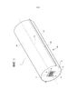
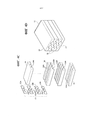
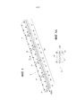
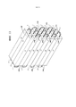
фиг. 1 - вид теплообменника в аксонометрии согласно предпочтительному варианту осуществления изобретения;FIG. 1 is a perspective view of a heat exchanger according to a preferred embodiment of the invention;
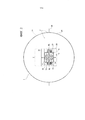
фиг. 2 - вид спереди в соответствии со стрелкой II с фиг. 1;FIG. 2 is a front view in accordance with arrow II of FIG. 1;
на фиг. 2А показано возможное расположение трубок внутри теплообменника;in FIG. 2A shows a possible arrangement of tubes inside a heat exchanger;
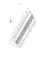
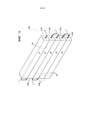
фиг. 3 - вид в аксонометрии в соответствии со стрелкой III с фиг. 1, показывающий сечение теплообменника вдоль продольной плоскости;FIG. 3 is a perspective view in accordance with arrow III of FIG. 1, showing a cross section of a heat exchanger along a longitudinal plane;
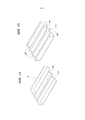
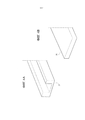
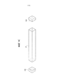
на фиг. 4А и фиг.4В показаны первый компонент и второй компонент, используемые в матрице теплообменника согласно изобретению;in FIG. 4A and 4B show a first component and a second component used in a heat exchanger matrix according to the invention;
фиг. 4С представляет собой вид в аксонометрии с пространственным разделением деталей части матрицы теплообменника в соответствии с изобретением, тогда как фиг. 4D представляет собой вид компонентов, показанных на фиг. 4С, в сборе; фиг. 5, 6А и 6В иллюстрируют дополнительные компоненты, которые составляют теплообменник в соответствии с изобретением;FIG. 4C is an exploded perspective view of a part of a heat exchanger matrix in accordance with the invention, while FIG. 4D is a view of the components shown in FIG. 4C, complete; FIG. 5, 6A and 6B illustrate additional components that make up the heat exchanger in accordance with the invention;
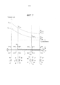
на фиг. 7 графически представлено техническое преимущество настоящего изобретения;in FIG. 7 is a graphical representation of the technical advantage of the present invention;
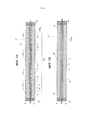
фиг. 8 - вид в аксонометрии матрицы теплообменника в соответствии с дополнительными вариантами осуществления изобретения, тогда как на фиг. 8А показан вид спереди в соответствии со стрелкой VIII/А на фиг. 8;FIG. 8 is a perspective view of a heat exchanger matrix in accordance with further embodiments of the invention, while in FIG. 8A is a front view in accordance with arrow VIII / A in FIG. eight;
на фиг. 9А и 9В представлены виды поперечного сечения, соответственно, матрицы согласно фиг.8 и варианта той же матрицы, тогда как фиг. 9С представляет собой вид с пространственным разделением деталей оболочки теплообменника; а такжеin FIG. 9A and 9B are cross-sectional views, respectively, of the matrix of FIG. 8 and a variant of the same matrix, while FIG. 9C is an exploded view of a heat exchanger shell; and
на фиг. 10 и 11 показаны виды в аксонометрии теплообменника согласно изобретению, выполненного в виде агрегата теплообменников согласно фиг. 9А или 9В.in FIG. 10 and 11 are perspective views of a heat exchanger according to the invention made in the form of a heat exchanger assembly according to FIG. 9A or 9B.
Осуществление изобретенияThe implementation of the invention
Номером ссылки 1 на фиг. 1 обозначен в целом теплообменник в соответствии с предпочтительным вариантом осуществления изобретения. Теплообменник 1 содержит сердечник 2 теплообменника и оболочку 4, выполненную из изоляционного материала и расположенную вокруг сердечника 2 теплообменника.
Сердечник 2 теплообменника, в свою очередь, содержит дополнительную оболочку 5, выполненную из огнеупорного материала и матрицу 6. Матрица 6 содержит пучок трубок, включающую в себя множество трубок 8, каждая из которых проходит в соответствующем продольном направлении. В предпочтительном варианте осуществления, проиллюстрированном здесь, продольное направление совпадает для всех трубок 8 с продольным направлением теплообменника 1, определяемым его продольной осью X1. Таким образом, трубки 8 параллельны друг другу.The
Трубки 8 пучка обеспечивают каналы потока для двух или более теплонесущих текучих сред, находящихся при разных температурах и в теплообменном отношении друг к другу. Эти каналы потока расположены в продольных направлениях соответствующих трубок 8. В случае предпочтительного варианта осуществления, проиллюстрированного здесь, направление каналов потока совпадает с продольным направлением X1 теплообменника.The
Например, при работе только с двумя теплонесущими текучими средами первая часть трубок 8 функционирует как канал потока для первой теплонесущей текучей среды, тогда как вторая часть (остальная часть) трубок 8 функционирует как канал потока для второй теплонесущей текучей среды. Разумеется, в соответствии с направлением каждого отдельного канала работа может идти в противотоке (обычно предпочтительно) или с потоками, двигающимися в одном направлении.For example, when working with only two heat transfer fluids, the first part of the
В других вариантах осуществления может быть более двух рабочих текучих сред и, следовательно, более двух каналов потока: это означает, что первая часть трубок 8 пучка обеспечивает канал потока для первой рабочей текучей среды, вторая часть трубок 8 пучка обеспечивает канал потока для второй рабочей текучей среды, третья часть трубок 8 пучка обеспечивает канал потока для третьей рабочей текучей среды и т.д.In other embodiments, there may be more than two working fluids and therefore more than two flow channels: this means that the first part of the
На фиг. 2 и 2А показано, что трубки 8 пучка трубок предпочтительно расположены в шахматном порядке, что в рассматриваемом здесь варианте осуществления соответствует расположению в вершинах и в центре тяжести правильного шестиугольника (или, эквивалентно, геометрии сетки из равносторонних треугольников). Следует отметить, что независимо от рассматриваемой схемы распределение трубок 8, переносящих первую рабочую текучую среду (например, горячую текучую среду, трубки 8Н), и трубок 8, переносящих вторую рабочую текучую среду (например, холодную текучую среду, трубки 8С), может быть разным. Например, как показано на фиг. 2А-1, в случае сетки из равносторонних треугольников в двух вершинах могут находиться трубки, в которых течет горячая текучая среда, тогда как третья вершина может быть занята трубкой, в которой течет холодная текучая среда.In FIG. 2 and 2A, it is shown that the
Возможны другие варианты расположения, как, например, на фиг. 2А-2 или фиг. 2А-3 (идентично показанному на фиг. 2А-1 за исключением геометрического расположения трубок 8Н вокруг трубок 8С): необязательно существует предпочтительное расположение, поскольку теплопроводность матрицы 6 имеет первостепенное значение по сравнению с теплопроводностью стенок трубок 8, так что возможные различия положения трубок компенсируются чрезвычайно высокой теплопроводностью матрицы (относительно теплопроводности стенки трубки).Other arrangements are possible, such as, for example, in FIG. 2A-2 or FIG. 2A-3 (identical to that shown in FIG. 2A-1 except for the geometrical arrangement of the
Расположение в шахматном порядке или расположение в виде сетки из равносторонних треугольников, рассматриваемое как предпочтительное с конструктивной точки зрения, может иметь мало значения с функциональной точки зрения по причинам, указанным выше: хотя отдельные расстояния между различными трубками 8 и различаются, но из-за высокой теплопроводности матрицы 6 они, по существу, эквивалентны с позиции сопротивления теплопередаче.A staggered arrangement or a grid arrangement of equilateral triangles, considered to be preferable from a structural point of view, may have little value from a functional point of view for the reasons mentioned above: although the individual distances between the
Как показано на фиг. 3, в представленном на ней варианте осуществления матрица 6 выполнена из теплопроводного материала, предпочтительно из меди или алюминия или синтетического алмаза, и имеет несколько секций 10, расположенных последовательно в продольном направлении X1 и разделенных соответствующими тепловыми барьерами 12, проходящими в направлении, перпендикулярном продольному направлению X1.As shown in FIG. 3, in the embodiment shown therein, the
В общем случае тепловые барьеры, разделяющие секции 10, проходят в направлении, перпендикулярном продольному направлению каждой из трубок 8: в рассматриваемом случае (предпочтительный вариант осуществления) это эквивалентно расширению, поперечному направлению X1, но в случае продольных направлений, которые не параллельны друг другу (будь то прямо- или криволинейные), тепловые барьеры 12 проходят в направлении, перпендикулярном каждому продольному направлению. Это может привести к вариантам осуществления, в которых тепловые барьеры проходят чисто поперек (ортогонально) только одному из продольных направлений, также имеющем компонент осевого расположения по отношению к другим продольным направлениям, а также к вариантам осуществления, в которых тепловые барьеры имеют многогранные поверхности, являющиеся локально ортогональными к каждому продольному направлению.In general, thermal
В проиллюстрированном варианте осуществления теплообменник 1 включает в себя матрицу 6 с десятью секциями 10 и девять тепловых барьеров 12, в которых каждый тепловой барьер 12 разделяет две смежные секции 10.In the illustrated embodiment, the
Разумеется, количество секций 10 зависит от осевой длины теплообменника 1, поскольку, как будет видно ниже, предпочтительно, чтобы секции 10 имели ограниченную осевую длину в соответствии с целью, для которой они были разработаны.Of course, the number of
По этой причине в случае вариантов осуществления теплообменника 1 с уменьшенной осевой длиной можно предусмотреть в пределе две смежные секции 10, разделенные одним тепловым барьером 12, но, как правило, имеется более двух секций 10 и более одного теплового барьера 12. Выбор количества секций 10 зависит от компромисса между эффективностью теплообменника и простотой конструкции. Эффективность теплообменника 1, в общем случае, растет с ростом количества секций 10, но, очевидно, это ведет к большей сложности конструкции.For this reason, in the case of embodiments of the
Следовательно, матрица 6 имеет модульную конструкцию, где каждый модуль соответствует одной секции 10, и, в свою очередь, каждая секция 10 также имеет некоторую модульную конструкцию.Therefore, the
Каждую секцию 10 фактически получают с помощью двух пар модульных элементов, в частности, первой пары первых модульных элементов 14 и второй пары вторых конструктивных модулей 16.Each
Со ссылкой на фиг. 2 и фиг. 4А и 4В далее приведено описание модульных элементов 14 и 16. Каждую секцию матрицы 6 получают путем установки друг на друга в прямом контакте одного модульного элемента 14, двух модульных элементов 16 и следующего модульного элемента 14 таким образом, что модульные элементы 14 расположены на концах пакета, соответствующего последовательности модульных элементов 14-16-16-14 и имеющего элементы 14 в конечном положении и элементы 16 в промежуточном положении.With reference to FIG. 2 and FIG. 4A and 4B, the following describes
Элементы 14, 16 выполнены, по существу, в виде пластины из теплопроводного материала (медь или другой материал с высокой теплопроводностью), имеют одинаковую опорную поверхность и содержат одну или несколько осевых канавок 14А или же, соответственно, 16А, имеющих полукруглое поперечное сечение.
Полукруглая форма в этом варианте осуществления требуется из-за того, что трубки 8, составляющие пучок трубок теплообменника 1, имеют круглое поперечное сечение, так что, когда канавки элемента 14 и элемента 16 совмещены, две полукруглые секции образуют единое целое, создавая осевую полость с круглым сечением, соответствующую внешней форме трубки 8, располагаемой в этой полости.The semicircular shape in this embodiment is required because the
Разумеется, в зависимости от сечения трубок 8, составляющих пучок трубок, канавки 14А, 16А могут иметь любую форму с тем единственным ограничением, что две совмещаемые канавки, образуют сечение, соответствующее внешней форме трубки из пучка трубок, чтобы обеспечить контакт между осевой полостью, созданной таким образом, и стенкой трубки.Of course, depending on the cross section of the
В рассматриваемом варианте осуществления элементы 14 имеют две осевые канавки 14А только на одной стороне элемента, тогда как элементы 16 имеют две канавки 16А на одной стороне (с тем же расположением и того же размера, что и канавки 14А, а также - как представляется очевидным - в том же количестве) и три канавки 16А на другой - противоположной - стороне.In this embodiment, the
Сторона, имеющая две канавки 16А, предназначена для совмещения со стороной элемента 14, имеющей две канавки 14А (таким образом контактируя с совмещаемыми канавками), тогда как сторона, имеющая три канавки 16А, предназначена для совмещения со стороной второго элемента 16, имеющей три канавки 16А (таким образом контактируя с совмещаемыми канавками). В результате, второй элемент 16 в обязательном порядке обращен своей стороной с двумя канавками 16А к элементу 14, в частности, к стороне 14А, имеющей две канавки, таким образом определяя последние две осевые полости секции (всего семь).A side having two
Обобщая вышесказанное, независимо от количества трубок 8 пучка трубок теплообменника 1 первый модульный элемент 14 содержит некоторое первое количество осевых канавок 14А только на его одной стороне, тогда как второй модульный элемент 16 содержит некоторое количество осевых канавок 16А, равное указанному первому количеству на его первой стороне, и некоторое второе количество осевых канавок, равное первому количеству, увеличенному на единицу, на его второй стороне, противоположной первой.Summarizing the above, regardless of the number of
Таким образом, когда стороны вышеуказанных первого и второго модульных элементов 14, 16, имеющие одинаковое количество канавок 14А, 16А, помещены друг против друга, возникает шахматное расположение сквозных отверстий, ориентированных вдоль продольной оси X1, где каждое сквозное отверстие выполнено с возможностью прохождения в нем соответствующей трубки 8 пучка трубок.Thus, when the sides of the aforementioned first and second
Это хорошо видно на изображении в аксонометрии с пространственным разделением деталей на фиг. 4С, а также в собранном виде на фиг. 4D, показывающим, по существу, секцию 10 матрицы в комбинации с тепловым барьером 12.This is clearly seen in a perspective view with a spatial separation of the parts in FIG. 4C, as well as assembled in FIG. 4D, showing essentially a
Снова обращаясь к фиг. 4С и 4D, можно видеть, что предпочтительно каждый тепловой барьер 12 проходит через все поперечное расширение секций 10, разделяя их на отсеки и изолируя их термически в целом друг от друга.Referring again to FIG. 4C and 4D, it can be seen that preferably each
Для этой цели тепловой барьер 12 может быть предусмотрен альтернативно как диафрагма, выполненная из теплоизолирующего материала, такого как оксид алюминия, графит, керамические материалы, стеклокерамика Macor®, оксиды магния, огнеупорные материалы или другие известные изоляционные материалы, а также может быть образован пустым зазором, содержащим только воздух или инертный газ или же откачанным до вакуума.For this purpose,
В предпочтительном варианте осуществления, таком как тот, который показан на фигурах и, в частности, на фиг. 4С и 4D, тепловой барьер 12 выполнен в виде диафрагмы, изготовленной из теплоизолирующего материала (еще раз - оксид алюминия, графит, керамические материалы, стеклокерамика Macor®, оксиды магния, огнеупорные материалы или другие эквивалентные изоляционные материалы), с модульной конструкцией, содержащей четыре части: две части 12А и две вторые части 12В, расположенные последовательно друг относительно друга в соответствии со схемой 12А-12 В- 12 В-12 А.In a preferred embodiment, such as that shown in the figures, and in particular in FIG. 4C and 4D, the
Части 12А имеют опорную поверхность, соответствующую поперечному сечению элементов 14, и выполнены с возможностью установки на соответствующий элемент 14. Части 12В, вместо этого, имеют опорную поверхность, соответствующую поперечному сечению элементов 16, и выполнены с возможностью установки на соответствующий элемент 16. Для частей диафрагмы 12 термин "опорная поверхность" используется потому, что они соответствуют, по существу, пластинам, т.е. элементам с малой осевой протяженностью.
Каждая первая часть 12А представляет собой пластину, выполненную из теплоизолирующего материала, предпочтительно оксида алюминия (или, вообще, любого из изоляционных материалов, указанных выше), по периметру которой имеются одно или несколько углублений 120, расположенных только на одной стороне.Each
Каждая вторая часть 12В представляет собой пластину, выполненную из теплоизолирующего материала, предпочтительно оксида алюминия (вообще, любого из изоляционных материалов, указанных выше), содержащую углубления 120 на первой стороне и на второй стороне периметра, противоположных друг другу.Each
Первая часть 12А содержит первое количество углублений 120 (в данном случае два), равное первому количеству осевых канавок 14А на модульном элементе 14.The
Вторая часть 12 В содержит:The second part of 12 V contains:
- количество углублений 120, равное первому количеству углублений 120 на вышеуказанной первой стороне периметра; а также- the number of
- второе количество углублений 120, равное первому количеству углублений, увеличенному на единицу, на вышеуказанной второй стороне периметра таким образом, что, когда стороны первой и второй частей 12А, 12В, имеющие одинаковое количество углублений 120, установлены друг против друга, возникает шахматное расположение отверстий, имеющих оси, параллельные продольному направлению X1, и имеющих одинаковое положение, количество и расположение, как отверстия в шахматном порядке, определенные пакетом модульных элементов 14, 16, 16, 14; поэтому специалисту понятно, что второе количество углублений 120 равно второму количеству канавок 16А на второй стороне модульного элемента 16 (или, эквивалентно, первому количеству осевых канавок 14А на модульном элементе 14 или на первой стороне модульного элемента 16).- the second number of
Затем каждая трубка 8 может быть вставлена, по сути, свободным скольжением в осевом направлении в последовательности осевых сквозных отверстий, характеризующейся чередованием осевого сквозного отверстия на секции 10, определяемого установкой модульных элементов 14 и/или 16 (14-16, 16-16) друг против друга, и осевого сквозного отверстия, определяемого установочными участками 12А и/или 12В (12А-12А, 12В-12В) друг против друга, а затем продолжающейся осевым сквозным отверстием в следующей секции 10, имеющей аналогичное положение.Then each
В случае если тепловой барьер 12 образован пустым зазором, содержащим только воздух или инертный газ или же вакуум, каждая трубка 8 может быть вставлена, по сути, свободным скольжением в осевом направлении в последовательности осевых сквозных отверстий, расположенных аналогично в каждой секции 10 (каждое отверстие определяется установкой модульных элементов 14 и/или 16 друг против друга).If the
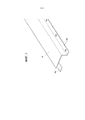
Как показано на фиг. 2, фиг. 4С и фиг. 4D, пакеты модульных элементов 14, 16, составляющих секции 10 (фиг. 3) матрицы 6, плотно сжаты вместе парой металлических профилей 18 (фиг. 5), имеющих, по существу, С-образное поперечное сечение.As shown in FIG. 2, FIG. 4C and FIG. 4D, packages of
Профили 18 расположены по всей осевой длине матрицы 6 и соединены друг с другом с помощью фланцевого соединения, здесь получаемого посредством болтов BL, входящих в отверстия на боковых фланцах 18А профилей 18.The
Разумеется, специалист понимает, что возможны другие формы соединений, например, с помощью кронштейнов с квадратным или прямоугольным сечением с болтами, закрепленными в верхней части, где элементы 14 и 16 будут уложены друг на друга, в результате чего усилие, создаваемое при вкручивании болтов, сжимает сами элементы вместе, или же с помощью сварки, или любым другим известным способом, способным сжать вышеуказанные элементы 14 и 16 вместе.Of course, the specialist understands that other forms of connections are possible, for example, using brackets with a square or rectangular cross section with bolts fixed in the upper part, where the
Оболочка, изготовленная из огнеупорного материала 5, расположена вокруг матрицы 6 и вставлена в призматическую полость, имеющую форму, комплементарную внешней форме оболочки 5, полученной в оболочке 4, изготовленной из теплоизолирующего материала, который также окружает матрицу 6.A shell made of
Оболочка 5 также имеет модульную конструкцию. В частности, как показано на фиг. 2 и 6А, оболочка 5 из огнеупорного материала, содержит два первых модульных элемента 20 из огнеупорного материала, показанных на фиг. 6 В, которые выполнены, по существу, как плоские пластины из огнеупорного материала, а также два вторых модульных элемента 22 из огнеупорного материала, имеющих, по существу, С-образное поперечное сечение, показанное на фиг. 6А.
Модульные элементы 20, 22 имеют осевую длину, равную осевой длине теплообменника, или, альтернативно, они могут иметь осевую длину, равную ее части, и могут иметь тепловые барьеры между ними, расположенные в положениях, совпадающих с тепловыми барьерами матрицы.The
Как можно видеть на фиг. 2, матрица 6, удерживаемая профилями 18, по существу, встроена в оболочку 5 из огнеупорного материала: два модульных элемента 20 расположены на противоположных сторонах матрицы 6 (относительно соединения между парой профилей 18), выступающих сбоку, чтобы идентифицировать две призматические подполости вокруг областей, занятых фланцами 18А.As can be seen in FIG. 2, the
В этих подполостях размещены два дополнительных модульных элемента 22, С-образная форма которых позволяет размещать болты BL и, конечно, фланцы 18А.In these subcavities, two additional
Предпочтительно оболочку 4 изоляционного материала, кроме того, удерживают снаружи два полуцилиндрических кожуха 24, соединенные вместе через продольные фланцы 26, которые также соединены болтами или сварены вместе.Preferably, the
Работа теплообменника 1 описана ниже.The operation of the
Как показано на фиг. 1 и фиг. 2, трубки 8 пучка трубок теплообменника выполнены с возможностью подачи в них при использовании двух рабочих текучих сред, имеющих разную температуру.As shown in FIG. 1 and FIG. 2, the
Концы трубок 8 могут сами функционировать как входные или выходные отверстия для рабочих текучих сред и могут быть непосредственно присоединены к рабочим частям другого компонента, например, к объединенному реактору окисления и газификации в сверхкритической воде, такому, как описанный в патентных заявках №102016000009465, 102016000009481, 102016000009512, поданных в тот же день от имени настоящего заявителя, или в рамках комбинированного процесса окисления и газификации в сверхкритической воде, такого, как описанный в патентной заявке №102015000011686, поданной 13 апреля 2015 г. Соединение можно получить с помощью фланцев или же трубных соединений.The ends of the
Независимо от способа, выбранного для соединения, через первый комплект трубок 8 (одна или несколько трубок) проходит первая рабочая текучая среда в первом направлении потока, а через второй комплект трубок 8 (в количестве, дополняющем общее количество по отношению к количеству первого комплекта) проходит вторая рабочая текучая среда во втором направлении потока, предпочтительно противоположном первому (работа в противотоке). Если количество рабочих текучих сред более двух, то могут быть рабочие текучие среды, идущие по соответствующим трубкам 8 в одном направлении, и рабочие текучие среды, идущие по трубкам 8 в противотоке.Regardless of the method chosen for the connection, the first working fluid passes in the first flow direction through the first set of tubes 8 (one or more tubes), and passes through the second set of tubes 8 (in an amount that is in addition to the total quantity relative to the amount of the first set) the second working fluid in a second flow direction, preferably opposite to the first (countercurrent operation). If the number of working fluids is more than two, then there can be working fluids going through the corresponding
В общем, теплообменник 1 можно использовать с рабочими текучими средами с различным давлением и с различным химическим составом. Стойкость к давлению и химическим веществам определяется стенками отдельных трубок 8, которые могут быть выбраны из моделей, обычно доступных на рынке. Трубки 8 для различных потребностей, обусловленных химическим составом и давлением рабочих текучих сред, могут быть изготовлены из простой стали для строительных целей или же из высокопрочной стали и могут иметь разную толщину стенок (например, для горячей текучей среды можно использовать трубку, изготовленную из Inconel 825, поскольку эта среда проявляет сильную коррозионную активность и имеет высокое давление, тогда как для холодной текучей среды можно использовать трубку из простой углеродистой стали, поскольку эта среда является некоррозионной и имеет низкое давление).In general, the
По каждой трубке может проходить различная текучая среда, отличающаяся химическим составом, давлением, температурой и другими физическими характеристиками.A different fluid can pass through each tube, which is distinguished by its chemical composition, pressure, temperature, and other physical characteristics.
Теплообмену между двумя (или более) рабочими текучими средами внутри теплообменника способствует при работе матрица 6.The heat exchange between two (or more) working fluids inside the heat exchanger is facilitated by the operation of the
Матрица 6 выполнена из материала с высокой теплопроводностью, ориентировочно от 100 до 400 Вт/м°С, но для различных нужд и для конкретных применений можно в качестве материала для матрицы 6 использовать прокатную сталь с теплопроводностью приблизительно 52 Вт/м°С или же для других применений (как, например, охлаждение микропроцессоров в специальных приложениях, в частности, в аэрокосмической отрасли) может быть использован синтетический алмаз с теплопроводностью приблизительно 1200 Вт/м°С, обеспечивая передачу теплового потока в радиальном направлении относительно трубок 8, идущего между первым и вторым комплектами трубок 8.
Использование матрицы 6 в качестве средства для теплообмена между трубками 8 и - как логическое следствие между текучими средами, протекающими в них, - позволяет исключить использование двухтрубной технологии, в то же время сохраняя эффективность теплообмена на том же уровне, если даже не увеличить ее.The use of the
Секционная конструкция матрицы 6, обусловленная наличием тепловых барьеров 12, в секциях которой находится матрица 6, является технически целесообразный для осевого ограничения распространения тепловых потоков. Другими словами, секционирование матрицы позволяет ограничить температурный градиент каждой секции в осевом направлении, существенно усиливая тепловые потоки в радиальном направлении (в плоскостях, перпендикулярных оси X1). По этой причине, как и предполагалось в начале, осевая длина секций 10 должна быть не слишком большой, чтобы предотвратить распространение тепла в осевом направлении вдоль поперечного сечения и, как следствие, снижение эффективности теплообмена.The sectional design of the
Продольное распространение тепловых потоков прерывается благодаря тепловым барьерам 12, изолирующим последовательные секции матрицы 6, тем самым повышая эффективность теплообменника. Осевое тепловое расширение трубок 8 является, кроме того, предпочтительным при их установке в свободно скользящем состоянии внутри матрицы 6, что позволяет избежать использования, например, дорогостоящих плавающих головок.The longitudinal propagation of heat fluxes is interrupted by
Таким образом, можно получить теплообменники любой длины с использованием трубок из высокопрочных материалов, таких как Inconel 825 или AISI 316L, которые являются коммерчески доступными и не требуют дорогостоящих процессов обработки, необходимых для изготовления трубок традиционного двухтрубного теплообменника.Thus, heat exchangers of any length can be obtained using tubes of high-strength materials, such as Inconel 825 or AISI 316L, which are commercially available and do not require the expensive processing processes necessary for the manufacture of tubes of a traditional two-pipe heat exchanger.
Стоимость производства теплообменника 1 намного ниже, чем у двухтрубного теплообменника той же мощности, поскольку в дополнение к минимальному количеству стружки для достижения требуемых допусков и размеров, эти трубки, как уже упоминалось, могут быть выбраны также из недорогих моделей, обычно уже присутствующих на рынке, тогда как в обработке трубок для двухтрубных теплообменников стружка представляет собой больший процент отходов, т.к. эти трубки получают путем механической обработки с удалением припуска литых монолитных слитков.The cost of
Поскольку матрица 6 позволяет трубкам 8 скользить относительно друг друга до некоторой степени (которая, в то же время, является незначительной по сравнению с обычным тепловым расширением, наблюдаемым в двухтрубных теплообменниках), это позволяет автоматически компенсировать тепловое расширение, полностью устраняя необходимость в плавающих головках или крупных компенсационных швах. Кроме того, любое возможное тепловое расширение трубок 8 может быть скомпенсировано за счет подсоединенных к ним трубок, которые идут, например, от других компонентов, расположенных вверху или внизу по потоку: при установке в эти трубки колен и/или изгибов их деформируемость позволяет устранять деформации, возникающие из-за возможного теплового расширения.Since the
Кроме того, следует принять во внимание, что модульная конструкция теплообменника 1 позволяет осуществлять довольно быстро модернизацию уже существующего оборудования. В частности, можно изменять теплообменную способность теплообменника 1 просто добавлением или удалением трубок 8 из матрицы 6 в соответствии с требуемой характеристикой.In addition, it should be borne in mind that the modular design of the
В этом смысле модульность теплообменника 1 дает возможность установки в любом продольном разрезе самого теплообменника одной или более дополнительных трубок 8С (холодная текучая среда) или же 8Н1 (горячая текучая среда). Каждая из этих дополнительных трубок принимает горячую текучую среду (8Н1) или холодную текучую среду (8С) при температуре, отличной от температуры горячей или холодной (соответственно) текучей среды на входе в концевые секции теплообменника (трубки 8Н, 8С), но соответствующей температуре, близкой к температуре горячей или холодной текучей среды, текущей в трубках 8Н, 8С в секции, где установлены дополнительные трубки. Цель состоит в том, чтобы максимизировать силу тяги (пропорциональную разности температуры текучих сред в отношении теплообмена), предотвращая образование т.н. "замедления теплообмена", т.е. появление таких секций теплообменника 1, в которых сила тяги исчезает, потому что текучие среды в отношении теплообмена имеют одинаковую температуру.In this sense, the modularity of the
Вышеприведенное проиллюстрировано на фиг. 7, где схематично показан для простоты теплообменник 1, имеющий только две трубки 8, в частности трубку 8Н для первой горячей текучей среды и трубку 8 С для первой холодной текучей среды, простирающиеся на всю продольную протяженность теплообменника (входы/выходы на концах теплообменника 1). Кроме того, теплообменник 1 содержит трубку 8Н', которая позволяет вводить вторую горячую текучую среду во входную секцию ниже по потоку от входной секции первой горячей текучей среды, причем выход находится в точке, соответствующей выходу первой горячей текучей среды. Наконец, теплообменник 1 содержит трубку 8С, которая позволяет вводить вторую холодную текучую среду в месте, соответствующем входу первой холодной текучей среды, причем эта вторая холодная текучая среда выходит из теплообменника в точке, соответствующей секции вверх по потоку от выхода первой холодной текучей среды. Ситуация представлена как работа в противотоке (как это видно также на диаграмме, изображенной выше теплообменника на фиг. 7).The foregoing is illustrated in FIG. 7, where a
Схематические виды, изображенные на фигуре ниже теплообменника, иллюстрируют его секции, соответствующие траекториям VIIА-VII-A, VII-B-VII-B; VII-C-VII-C; VII-D-VII-D; VII-E-VII-E; VII-F-VII-F, и обозначены буквами А, В, С, D, Е, F, соответственно. Секции, где установлены дополнительные трубки, соответствуют буквам D, В.The schematic views shown in the figure below the heat exchanger illustrate its sections corresponding to the trajectories VIIA-VII-A, VII-B-VII-B; VII-C-VII-C; VII-D-VII-D; VII-E-VII-E; VII-F-VII-F, and are indicated by the letters A, B, C, D, E, F, respectively. The sections where additional tubes are installed correspond to the letters D, B.
Ссылки, принятые на диаграмме, приведенные выше схематического изображения теплообменника 1, кроме того, имеют следующее значение:The links adopted in the diagram above the schematic representation of the
TH1IN: температура первой горячей рабочей текучей среды на входе в теплообменник 1;TH1IN: temperature of the first hot working fluid at the inlet to
TH2IN: температура второй горячей рабочей текучей среды на входе в секцию D на теплообменнике 1;TH2IN: temperature of the second hot working fluid at the inlet to section D on the
TH10UT: температура первой горячей рабочей текучей среды на выходе из теплообменника 1;TH10UT: temperature of the first hot working fluid at the outlet of
TH2OUT: температура второй горячей рабочей текучей среды на выходе из теплообменника 1;TH2OUT: temperature of the second hot working fluid at the outlet of the
TC1IN: температура первой холодной рабочей текучей среды на входе в теплообменник 1;TC1IN: temperature of the first cold working fluid at the inlet to
TC2IN: температура второй холодной рабочей текучей среды на входе в теплообменник 1;TC2IN: temperature of the second cold working fluid at the inlet to the
ТС1OUT: температура первой холодной рабочей текучей среды на выходе из теплообменника 1; а такжеTC1OUT: temperature of the first cold working fluid at the outlet of the
TC2OUT: температура второй холодной рабочей текучей среды на выходе из секции В теплообменника 1.TC2OUT: temperature of the second cold working fluid at the outlet of section B of the
Как можно заметить, имеет место полное подобие температурных профилей горячих рабочих текучих сред и холодных рабочих текучих сред: вторая горячая рабочая текучая среда имеет входную температуру TH2IN, идентичную температуре первой горячей текучей среды в секции D, и выходную температуру TH2OUT, идентичную выходной температуре TH1OUT первой горячей текучей среды. Вторая холодная рабочая текучая среда имеет входную температуру TC2IN, идентичную входной температуре первой холодной текучей среды TC1IN, и выходную температуру TC2OUT, идентичную температуре первой холодной текучей среды в секции В.As you can see, there is a complete similarity between the temperature profiles of hot working fluids and cold working fluids: the second hot working fluid has an inlet temperature TH2IN identical to the temperature of the first hot fluid in section D and an outlet temperature TH2OUT identical to the outlet temperature TH1OUT of the first hot fluid. The second cold working fluid has an inlet temperature TC2IN identical to the inlet temperature of the first cold fluid TC1IN and an outlet temperature TC2OUT identical to the temperature of the first cold fluid in section B.
В альтернативных вариантах осуществления изобретения, кроме того, оболочка 4 из изоляционного материала сама по себе может быть изготовлена из огнеупорного изоляционного материала, тем самым устраняя необходимость в оболочке 5. Эффективность того или иного решения зависит, конечно, от технических требований и затрат, связанных с каждой конструкцией.In alternative embodiments of the invention, in addition, the
В дополнение ко всем преимуществам, указанным выше, такая модульная конструкция теплообменника 1 также подходит для производства теплообменников, состоящих из наборов теплообменников 1* (имеющих функцию модульных теплообменников или, более точно, модульных теплообменных агрегатов), связанных друг с другом по текучей среде в соответствии с логикой, которая зависит от потребностей (последовательные, параллельные или смешанные соединения). По существу, в этих вариантах осуществления каждый теплообменник 1 сохраняет свою собственную модульную конструкцию и одновременно функционирует как конструктивный модуль для теплообменника более высокого уровня. Конечно, можно также использовать теплообменник 1* как независимое устройство: то, что будет описано далее, следует понимать просто как возможный и предпочтительный вариант применения.In addition to all the advantages mentioned above, this modular design of the
Пример этого варианта осуществления представлен на фиг. 8-11. Фиг. 10 и 11 показывают теплообменник 100, собранный из нескольких теплообменников 1*, в двух различных вариантах: один (фиг. 10) - одномерный массив (или линейный массив), другой (фиг. 11) - множественный массив (или двухмерный массив).An example of this embodiment is shown in FIG. 8-11. FIG. 10 and 11 show a
Фиг. 8, 9А, 9В и 9С иллюстрируют, вместо этого, теплообменник 1 в предпочтительном варианте осуществления в свете применения, показанного на фиг. 10 и 11.FIG. 8, 9A, 9B and 9C illustrate, instead,
Теплообменник 1* на фиг. 8, 9А и 9В содержит сердечник 2 теплообменника и оболочку 4 из изоляционного материала, установленную вокруг сердечника 2 теплообменника. Сердечник 2 теплообменника преимущественно не имеет дополнительной оболочки 5 из огнеупорного материала, в основном для соблюдения габаритных размеров; в других вариантах осуществления, однако, можно предусмотреть также оболочку 5.The
Сердечник 2 теплообменника содержит матрицу 6, в которой в этих вариантах осуществления размещается пучок трубок, включая пару трубок 8, каждая из которых проходит в соответствующем продольном направлении. В предпочтительном варианте, проиллюстрированном здесь, продольное направление совпадает для всех трубок 8 с продольным направлением соответствующего теплообменника 1, идентифицированным его продольной осью X1. Трубки 8, следовательно, все параллельны друг другу. Конечно, можно предусмотреть любое количество трубок 8.The
Кроме того, на концах пучка трубок установлены первая концевая пластина В1 и вторая концевая пластина В2, выполненные из изоляционного материала. Трубки 8, выходящие из каждого теплообменника 1*, проходят через концевые пластины В1 и В2.In addition, at the ends of the tube bundle, a first end plate B1 and a second end plate B2 are made of insulating material.
Ссылка 24 (фиг. 9С) здесь обозначает металлический кожух призматической формы с функцией, как и у описанного выше кожуха 24, только адаптированный к новой форме теплообменника 1 (призматическая, а не цилиндрическая, хотя может быть предусмотрен и цилиндрический вариант). Кожух 24 установлен снаружи оболочки 4 и закрыт на противоположных концах двумя концевыми пластинами 24В, обеспечивающим возможность прохождения через них трубок 8.Reference 24 (Fig. 9C) here denotes a metal casing of a prismatic shape with a function, as with the
Трубки 8 пучка обеспечивают каналы потока для двух (или более) теплонесущих текучих сред, имеющих разную температуру и находящихся в состоянии теплообмена друг с другом. Эти каналы потока расположены в продольных направлениях соответствующих трубок 8. В случае предпочтительного варианта осуществления, проиллюстрированного здесь, направление каналов потока совпадает с продольным направлением X1 теплообменника.The
Также в этом варианте осуществления матрица 6 выполнена из теплопроводного материала, предпочтительно из меди или алюминия или синтетического алмаза, и содержит несколько секций 10, расположенных последовательно в продольном направлении X1 и чередующихся с соответствующими тепловыми барьерами 12, вытянутыми в направлении, перпендикулярном к продольному направлению X1 (фиг. 8, 9А).Also in this embodiment, the
Тепловые барьеры 12, разделяющие секции 10, вытянуты в направлении, перпендикулярном продольному направлению каждой из трубок 8: в этом случае это эквивалентно расположению в направлении, перпендикулярном направлению X1, но в случае продольных направлений, которые не параллельны друг другу (независимо от того, являются ли они прямо- или криволинейными), тепловые барьеры 12 вытянуты в направлении, перпендикулярном к каждому продольному направлению.The
В варианте осуществления, показанном на фиг. 9А, матрица 6 содержит пятнадцать секций 10 и четырнадцать тепловых барьеров 12, где каждый тепловой барьер 12 разделяет две смежные секции 10. Матрица показана в увеличенном виде на фиг. 8, но для целей иллюстрации изображено только пять из пятнадцати секций.In the embodiment shown in FIG. 9A, the
Конечно, количество секций 10 зависит от осевой длины теплообменника 1*, поскольку, как будет видно ниже, предпочтительно, чтобы секции 10 имели ограниченную осевую длину с учетом результатов, для которых они разработаны.Of course, the number of
Каждая секция 10 имеет модульную конструкцию, как описано ранее. В частности, каждую секцию 10 получают путем установки двух модульных элементов 14, аналогичных описанным ранее, друг на друга, т.е. модульных элементов с полукруглыми канавками 14А только с одной стороны. В показанном здесь варианте осуществления (см. фиг. 8А) модульные элементы 14 контактируют только с поверхностью между канавками 14 А.Each
Предпочтительно, S-образный зажим, обозначенный здесь как CL, зажимает трубки 8 на тепловых барьерах 12.Preferably, the S-shaped clamp, designated here as CL, clamps the
Как показано на фиг. 10 и 11, теплообменник 100 содержит несколько теплообменников 1*, трубки 8 которых связаны по текучей среде посредством соединений, обозначенных здесь как J (эти соединения здесь имеют U-образную форму).As shown in FIG. 10 and 11, the
В варианте осуществления, показанном на фиг. 10, теплообменник 100 содержит одномерный (линейный) массив теплообменников 1*, расположенных рядом друг с другом (на фиг. 10 теплообменники 1* расположены друг над другом, но на практике -при условии, что гидравлические соединения выполнены, как показано или в соответствии с потребностями, - можно устроить теплообменник 100 с любой ориентацией), где каждое соединение J поворачивает поток текучей среды, по существу, на 180°, обеспечивая присоединение к трубкам 8 ближайшего примыкающего теплообменника 1*. Теплообменник 100, по существу, представляет собой комплекс теплообменных "картриджей" (или модульных теплообменных агрегатов), каждый из которых состоит из одного теплообменника 1*. Соединения J могут иметь любую форму, соответственно приводя к возникновению теплообменников 100, конструкция которых может отличаться от того, что показано на фиг. 10 и 11. Каждое соединение представляет собой трубную секцию, предназначенную для соединения с трубкой 8 вверх по потоку и с трубкой 8 вниз по потоку. Кроме того, соединения J предпочтительно изолированы с помощью покрытия из теплоизолирующего материала. Кроме того, соединения J, по существу, обладают большей деформируемостью, чем остальная конструкция, так что они могут способствовать компенсации дифференциальных тепловых расширений.In the embodiment shown in FIG. 10, the
Дополнительно, теплообменник 100, также рассматриваемый в целом и со ссылкой на продольное направление трубок 8, весь целиком содержит матрицу из теплопроводного материала, в которой расположены трубки 8 и которая состоит из секций 10, разделенных тепловыми барьерами 12. Это условие необходимо контролировать при разработке теплообменника 100. Следует, кроме того, иметь в виду, что межкартриджные трубные секции 1* (соединения J) сами по себе являются тепловыми барьерами по отношению к матрице 6.Additionally, the
По существу, в теплообменнике 100 каждый тепловой барьер 12 - проходящий в направлении, перпендикулярном направлению X1, - состоит из комплекса соединений J, гидравлически соединяющих трубки 8 модульных теплообменных агрегатов теплообменника 100, где модульные теплообменные агрегаты соответствуют теплообменникам 1*.Essentially, in the
Каждый модульный теплообменный агрегат 1* фактически определяет секцию 10* матрицы теплообменника 100. В случае варианта осуществления, показанного на фиг. 9А, секция 6 матрицы каждого модульного теплообменного агрегата 1*, в свою очередь, состоит из множества секций 10, разделенных тепловыми барьерами 12, проходящими в направлении, перпендикулярном продольному направлению X1.Each modular
То же самое относится к варианту осуществления по фиг. 11, в котором три линейных массива теплообменников 1* расположены рядом друг с другом, образуя двумерный массив из 8 х 3 теплообменников 1*.The same applies to the embodiment of FIG. 11, in which three linear arrays of 1 * heat exchangers are located next to each other, forming a two-dimensional array of 8 x 3 1 * heat exchangers.
Также в этом варианте осуществления трубки 8 каждого теплообменника 1* гидравлически присоединены посредством соединений, обозначенных здесь как J (эти соединения здесь имеют U-образную форму), к соответствующим трубкам 8, по меньшей мере, одного другого теплообменника 1*, где каждое соединение J в этом варианте осуществления поворачивает поток текучей среды, по существу, на 180°.Also in this embodiment, the
В этом случае, однако, соединения J предназначены как для гидравлического соединения теплообменников 1*, установленных друг над другом, так и для гидравлического соединения теплообменников 1*, расположенных рядом друг с другом при переходе от одного линейного массива к другому. Со ссылкой на фигуру и предполагая, что направления вверх/вниз и вправо/влево ясны из изображения на самой фигуре (без каких-либо ограничений, связанных с установкой теплообменника 100), расположение соединений J обеспечивает канал потока для теплонесущих текучих сред, который проходит из теплообменника 1 * вниз влево по вертикали вдоль левого линейного массива и затем переходит к центральному линейному массиву, идущему прямо вниз, и, наконец, переходит в правый линейный массив, работая прямо вверх, чтобы закончить в теплообменнике 1* в верхнем правом углу (ясно, что направление обхода линейного массива зависит от направления потока текучих сред в трубках 8, что, в свою очередь, зависит от режима работы - одинаковое направление течения или противоток (последнее предпочтительнее)). Кроме того, очевидно, что наличие чередующихся соединений J на обеих сторонах линейного массива фактически заставляет текучие среды течь вверх или вниз по массивам по извилистому пути в плоскости каждого массива.In this case, however, connections J are intended for both hydraulic connection of
Однако в целом путь для каждой из текучих сред может быть любым. В зависимости от типа теплонесущих текучих сред и потребностей можно задать с помощью соединений J каналы с различной формой (например, спиральный), а также с условиями соединения, отличными от описанного последовательного соединения. Можно реализовать, например, параллельное соединение или смешанное последовательно-параллельное соединение.However, in general, the path for each of the fluids can be any. Depending on the type of heat-carrying fluids and needs, it is possible to specify channels with various shapes (for example, spiral) using compounds J, as well as with connection conditions different from the described serial connection. You can implement, for example, a parallel connection or a mixed series-parallel connection.
Следует, однако, иметь в виду, что, как показано на фиг. 9В, в связи с использованием теплообменника 1 такого типа в качестве конструктивного модуля для теплообменника 100 более высокого уровня, можно предусмотреть оснащение теплообменника 1* матрицей 6, содержащей только одну секцию 10, при условии расположения на ее концах первого теплового барьера 12 и второго теплового барьера 12.However, it should be borne in mind that, as shown in FIG. 9B, in connection with the use of this type of
Таким образом, когда теплообменник 100 собран, он содержит в любом случае признаки в соответствии с настоящим изобретением, т.е. наличие тепловых барьеров 12, которые отделяют матрицу (рассматриваемую здесь во всей разработке теплообменника 100) в направлении, перпендикулярном продольному направлению трубок 8. Опять же, межкартриджные трубные секции 1* (соединения J) сами по себе представляют собой тепловые барьеры по отношению к массивам 6.Thus, when the
Каждый модульный теплообменный агрегат 1* фактически определяет секцию 10* теплопроводной матрицы теплообменника 100. В этом случае, однако, секция матрицы теплообменника 100 продолжается в каждом агрегате 1*.Each modular
Наконец, следует отметить, что присутствие соединений J позволяет сохранять признаки в соответствии с изобретением также в еще нескольких вариантах, в которых матрица 6 состоит из одной секции, а тепловые барьеры 12 на концах отсутствуют: в этом случае оставались бы только межкартриджные трубные секции 1* (т.е. соединения J), образующие тепловые барьеры, перпендикулярные продольному направлению X1.Finally, it should be noted that the presence of compounds J allows preserving the features in accordance with the invention also in several other variants, in which the
Разумеется, детали конструкции и варианты осуществления могут широко варьироваться в отношении того, что было описано и проиллюстрировано здесь, без отхода от объема настоящего изобретения, определенного приложенной формулой изобретения.Of course, the structural details and embodiments may vary widely with respect to what has been described and illustrated here, without departing from the scope of the present invention as defined by the appended claims.
Claims (37)
Applications Claiming Priority (3)
| Application Number | Priority Date | Filing Date | Title |
|---|---|---|---|
| IT102016000009566 | 2016-01-29 | ||
| ITUB2016A000089A ITUB20160089A1 (en) | 2016-01-29 | 2016-01-29 | HEAT EXCHANGER |
| PCT/IB2017/050445 WO2017130149A1 (en) | 2016-01-29 | 2017-01-27 | Heat exchanger |
Publications (3)
| Publication Number | Publication Date |
|---|---|
| RU2018128046A RU2018128046A (en) | 2020-03-02 |
| RU2018128046A3 RU2018128046A3 (en) | 2020-03-05 |
| RU2717726C2 true RU2717726C2 (en) | 2020-03-25 |
Family
ID=55919828
Family Applications (1)
| Application Number | Title | Priority Date | Filing Date |
|---|---|---|---|
| RU2018128046A RU2717726C2 (en) | 2016-01-29 | 2017-01-27 | Heat exchanger |
Country Status (9)
| Country | Link |
|---|---|
| US (1) | US11187465B2 (en) |
| EP (1) | EP3408601B1 (en) |
| JP (1) | JP2019507307A (en) |
| CN (1) | CN108779967B (en) |
| CA (1) | CA3010569A1 (en) |
| ES (1) | ES2769355T3 (en) |
| IT (1) | ITUB20160089A1 (en) |
| RU (1) | RU2717726C2 (en) |
| WO (1) | WO2017130149A1 (en) |
Families Citing this family (3)
| Publication number | Priority date | Publication date | Assignee | Title |
|---|---|---|---|---|
| IT201700091905A1 (en) * | 2017-08-08 | 2019-02-08 | David S R L | "Thermal energy storage device" |
| GB2586145A (en) * | 2019-08-07 | 2021-02-10 | Ibj Tech Ivs | Improvements in or relating to heat exchangers |
| JP7304919B2 (en) * | 2021-10-01 | 2023-07-07 | 均賀科技股▲ふん▼有限公司 | heat exchanger structure |
Citations (5)
| Publication number | Priority date | Publication date | Assignee | Title |
|---|---|---|---|---|
| SU361006A1 (en) * | 1967-10-27 | 1972-12-07 | мип имо | METHOD OF MANUFACTURING HEAT-EXCHANGE TOOLS FROM POLYMER MATERIALS |
| US3999602A (en) * | 1975-10-21 | 1976-12-28 | The United States Of America As Represented By The United States Energy Research And Development Administration | Matrix heat exchanger including a liquid, thermal couplant |
| RU13414U1 (en) * | 1998-11-20 | 2000-04-10 | Рыжов Виктор Григорьевич | HEAT EXCHANGER |
| GB2361054A (en) * | 2000-02-04 | 2001-10-10 | Nnc Ltd | Heat exchanger |
| RU2493473C1 (en) * | 2012-03-21 | 2013-09-20 | Борис Владимирович Крайнов | Removable modular heat insulation |
Family Cites Families (26)
| Publication number | Priority date | Publication date | Assignee | Title |
|---|---|---|---|---|
| US1799626A (en) * | 1929-07-08 | 1931-04-07 | Refinery Engineers Inc | Heat exchanger |
| US3409075A (en) * | 1965-08-20 | 1968-11-05 | Union Carbide Corp | Matrix heat exchange cores |
| GB1426723A (en) * | 1972-04-27 | 1976-03-03 | Axstane Properties Ltd | Heat exchanger |
| US4232732A (en) * | 1978-04-24 | 1980-11-11 | Johnson Albert V | Heat arrester boot for room stove |
| US4497365A (en) * | 1983-08-15 | 1985-02-05 | John Boyer | Heat exchanger |
| CN2237217Y (en) * | 1995-01-25 | 1996-10-09 | 冶金工业部鞍山焦化耐火材料设计研究院 | Central heat exchanging heat pipe heat exchanger |
| US6117203A (en) * | 1997-11-10 | 2000-09-12 | Kruger, Inc. | Pathogen reduction system used in treating wastewater |
| US7216696B2 (en) * | 1999-09-23 | 2007-05-15 | Ferraro Joseph C | External flue heat exchangers |
| JP2001153572A (en) * | 1999-12-02 | 2001-06-08 | Kawasaki Steel Corp | Heat-transfer-block-type heat exchanger |
| US6939505B2 (en) * | 2002-03-12 | 2005-09-06 | Massachusetts Institute Of Technology | Methods for forming articles having very small channels therethrough, and such articles, and methods of using such articles |
| US20050034847A1 (en) * | 2003-08-11 | 2005-02-17 | Robert Graham | Monolithic tube sheet and method of manufacture |
| US7191824B2 (en) * | 2003-11-21 | 2007-03-20 | Dana Canada Corporation | Tubular charge air cooler |
| CN2896189Y (en) * | 2006-03-17 | 2007-05-02 | 张德地 | Tube-still heat exchanger |
| US8322406B2 (en) * | 2008-07-14 | 2012-12-04 | University Of Central Florida Research Foundation, Inc. | Thermally conductive porous element-based recuperators |
| CA3024293A1 (en) * | 2009-02-27 | 2010-09-02 | Inventys Thermal Technologies Inc. | Parallel passage fluid contactor structure |
| TW201109078A (en) * | 2009-04-30 | 2011-03-16 | Corning Inc | Minireactor array |
| US20120082601A1 (en) * | 2009-05-31 | 2012-04-05 | Corning Incorporated | Honeycomb reactor or heat exchanger mixer |
| US8051902B2 (en) * | 2009-11-24 | 2011-11-08 | Kappes, Cassiday & Associates | Solid matrix tube-to-tube heat exchanger |
| GB2501413B (en) * | 2011-01-31 | 2017-06-07 | Mitsubishi Electric Corp | Heat exchanger, method of making the same, and refrigeration cycle apparatus including the same |
| CN103429982B (en) * | 2011-02-04 | 2016-06-29 | 洛克希德马丁公司 | There is the heat exchanger of foam fin |
| US9464847B2 (en) * | 2011-02-04 | 2016-10-11 | Lockheed Martin Corporation | Shell-and-tube heat exchangers with foam heat transfer units |
| CN103502763A (en) * | 2011-05-06 | 2014-01-08 | 三菱电机株式会社 | Heat exchanger and refrigeration cycle device provided with same |
| WO2013126449A1 (en) * | 2012-02-21 | 2013-08-29 | Ceramatec, Inc. | Compact ft combined with micro-fibrous supported nano-catalyst |
| CA2839884C (en) * | 2013-02-19 | 2020-10-27 | Scambia Holdings Cyprus Limited | Plate heat exchanger including separating elements |
| US20150083382A1 (en) * | 2013-09-24 | 2015-03-26 | Zoneflow Reactor Technologies, LLC | Heat exchanger |
| TWI638696B (en) * | 2014-02-14 | 2018-10-21 | 日商亞伊色爾股份有限公司 | Method of producing structure, structure and heat exchanger |
-
2016
- 2016-01-29 IT ITUB2016A000089A patent/ITUB20160089A1/en unknown
-
2017
- 2017-01-27 RU RU2018128046A patent/RU2717726C2/en active
- 2017-01-27 EP EP17710049.2A patent/EP3408601B1/en active Active
- 2017-01-27 ES ES17710049T patent/ES2769355T3/en active Active
- 2017-01-27 JP JP2018539383A patent/JP2019507307A/en active Pending
- 2017-01-27 CN CN201780008805.2A patent/CN108779967B/en active Active
- 2017-01-27 WO PCT/IB2017/050445 patent/WO2017130149A1/en active Application Filing
- 2017-01-27 US US16/073,118 patent/US11187465B2/en active Active
- 2017-01-27 CA CA3010569A patent/CA3010569A1/en active Pending
Patent Citations (5)
| Publication number | Priority date | Publication date | Assignee | Title |
|---|---|---|---|---|
| SU361006A1 (en) * | 1967-10-27 | 1972-12-07 | мип имо | METHOD OF MANUFACTURING HEAT-EXCHANGE TOOLS FROM POLYMER MATERIALS |
| US3999602A (en) * | 1975-10-21 | 1976-12-28 | The United States Of America As Represented By The United States Energy Research And Development Administration | Matrix heat exchanger including a liquid, thermal couplant |
| RU13414U1 (en) * | 1998-11-20 | 2000-04-10 | Рыжов Виктор Григорьевич | HEAT EXCHANGER |
| GB2361054A (en) * | 2000-02-04 | 2001-10-10 | Nnc Ltd | Heat exchanger |
| RU2493473C1 (en) * | 2012-03-21 | 2013-09-20 | Борис Владимирович Крайнов | Removable modular heat insulation |
Also Published As
| Publication number | Publication date |
|---|---|
| JP2019507307A (en) | 2019-03-14 |
| EP3408601A1 (en) | 2018-12-05 |
| US11187465B2 (en) | 2021-11-30 |
| CA3010569A1 (en) | 2017-08-03 |
| RU2018128046A3 (en) | 2020-03-05 |
| RU2018128046A (en) | 2020-03-02 |
| ES2769355T3 (en) | 2020-06-25 |
| CN108779967A (en) | 2018-11-09 |
| ITUB20160089A1 (en) | 2017-07-29 |
| EP3408601B1 (en) | 2019-11-13 |
| US20190041136A1 (en) | 2019-02-07 |
| WO2017130149A1 (en) | 2017-08-03 |
| CN108779967B (en) | 2020-04-14 |
Similar Documents
| Publication | Publication Date | Title |
|---|---|---|
| EP2176616B1 (en) | Heat exchanger | |
| US4438809A (en) | Tapered plate annular heat exchanger | |
| RU2717726C2 (en) | Heat exchanger | |
| JP4728243B2 (en) | Improved heat exchanger housing and seal | |
| RU2348883C1 (en) | Plate-type heat-exchanger | |
| JP2008286437A (en) | Heat exchanger | |
| US11512902B2 (en) | Flow baffles for shell and tube heat exchangers | |
| US11306972B2 (en) | Shell and tube heat exchangers | |
| EP3719431A2 (en) | Charge air cooler | |
| CN114353546A (en) | Ship centralized intermediate cooling system | |
| JP6309525B2 (en) | Heat exchanger assembly | |
| WO2020009734A1 (en) | Flow baffles for shell and tube heat exchangers | |
| JPS6229892A (en) | Heat exchanger having finned heat transmission pipes | |
| RU2386095C2 (en) | Heat exchanger | |
| CN211824039U (en) | Aluminum heat exchanger | |
| RU181420U1 (en) | SHELL-TUBULATED HEAT EXCHANGE UNIT | |
| RU2451887C1 (en) | Shell-and-tube heat exchanger | |
| RU2559412C1 (en) | Plate and shell heat exchanger | |
| CN116182600A (en) | Brayton cycle integrated heat exchanger of submarine aircraft and heat exchange method |