RU2717706C1 - Device for femoral bone treatment - Google Patents
Device for femoral bone treatment Download PDFInfo
- Publication number
- RU2717706C1 RU2717706C1 RU2019125840A RU2019125840A RU2717706C1 RU 2717706 C1 RU2717706 C1 RU 2717706C1 RU 2019125840 A RU2019125840 A RU 2019125840A RU 2019125840 A RU2019125840 A RU 2019125840A RU 2717706 C1 RU2717706 C1 RU 2717706C1
- Authority
- RU
- Russia
- Prior art keywords
- tube
- holes
- tubes
- rod
- endoscope
- Prior art date
Links
Images

Classifications
-
- A—HUMAN NECESSITIES
- A61—MEDICAL OR VETERINARY SCIENCE; HYGIENE
- A61B—DIAGNOSIS; SURGERY; IDENTIFICATION
- A61B17/00—Surgical instruments, devices or methods, e.g. tourniquets
- A61B17/56—Surgical instruments or methods for treatment of bones or joints; Devices specially adapted therefor
- A61B17/58—Surgical instruments or methods for treatment of bones or joints; Devices specially adapted therefor for osteosynthesis, e.g. bone plates, screws, setting implements or the like
- A61B17/68—Internal fixation devices, including fasteners and spinal fixators, even if a part thereof projects from the skin
- A61B17/72—Intramedullary pins, nails or other devices
Abstract
Description
Изобретение относится к медицине, а именно к оперативной ортопедии и может быть использовано для обработки бедренной кости при первичном и ревизионном эндопротезировании тазобедренного сустава.The invention relates to medicine, namely to operative orthopedics and can be used to treat the femur in primary and revision hip arthroplasty.
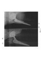
Ревизионное эндопротезирование тазобедренного сустава, в частности повторная установка бедренного компонента эндопротеза, включает в себя несколько этапов, одним из которых, и часто наиболее сложным, является подготовка канала бедренной кости. Одной из основных технических трудностей при обработке канала бедренной кости является правильное позиционирование инструментов для обработки, чтобы исключить возможные повреждения кортикального слоя бедренной кости. На фиг. 6 представлена рентгенограмма пациента с нестабильностью бедренного компонента эндопротеза, на которой сформирован «новый канал» от ножки, не соответствующий каналу бедренной кости.Revision hip arthroplasty, in particular reinstallation of the femoral component of the endoprosthesis, involves several steps, one of which, and often the most difficult, is the preparation of the femoral canal. One of the main technical difficulties in processing the femoral canal is the correct positioning of the instruments for processing in order to exclude possible damage to the cortical layer of the femur. In FIG. Figure 6 shows a radiograph of a patient with instability of the femoral component of the endoprosthesis, on which a “new channel” from the leg is formed that does not correspond to the channel of the femur.
В случае, если был установлен эндопротез цементной фиксации, то необходимо удаление костного цемента, которым был фиксирован установленный ранее бедренный компонент (ножка). Удаление костного цемента со стенок бедренного канала и так называемой «цементной пробки» возможно двумя основными способами. Наиболее травматичным является остеотомия бедренной кости. Второй способ - это удаление костного цемента непосредственно из бедренного канала через отверстие, которое остается после удаления ножки (в области шейки бедренной кости).If a cement fixation endoprosthesis was installed, then bone cement must be removed, which was used to fix the previously installed femoral component (leg). Removing bone cement from the walls of the femoral canal and the so-called “cement plug” is possible in two main ways. The most traumatic is osteotomy of the femur. The second method is the removal of bone cement directly from the femoral canal through the hole that remains after the removal of the leg (in the neck of the femur).
После удаления костного цемента, а также в случае бесцементного эндопротезирования далее проводится рассверливание канала бедренной кости или обработка ее специальными развертками (рашпилями).After removal of bone cement, as well as in the case of cementless endoprosthetics, the femoral canal is drilled or processed with special reamers (rasps).
Известно устройство для обработки бедренной кости, описанное Campbell's operative orthopaedics. - 11th ed. / [edited by] S. Terry Canale, James H. Beaty; editorial assistance by Kay Daugherty and Linda Jones; art coordination by Barry Burns. E. Устройство состоит из централизатора для сверел и набора сверел. При обработке бедренной кости централизатор вставляется в канал бедренной кости, внутрь его вставляется сверло, которым рассверливается содержимое канала (костный цемент, костная ткань). Недостатком устройства является отсутствие возможности контроля положения сверла при обработке канала, следствием чего может быть перфорация бедренной кости и повреждение сосудов и нервов, окружающих бедренную кость (см. фиг. 6).A femoral treatment device is described by Campbell's operative orthopedics. - 11th ed. / [edited by] S. Terry Canale, James H. Beaty; editorial assistance by Kay Daugherty and Linda Jones; art coordination by Barry Burns. E. The device consists of a centralizer for drills and a set of drills. When processing the femur, the centralizer is inserted into the canal of the femur, a drill is inserted inside it, with which the contents of the canal are drilled (bone cement, bone tissue). The disadvantage of this device is the inability to control the position of the drill during processing of the channel, which may result in perforation of the femur and damage to the vessels and nerves surrounding the femur (see Fig. 6).
Известно устройство, описанное Michiaki Takagi, Yasunobu Tamaki, Shinji Kobayashi et al. Cement removal and bone bed preparation of the femoral medullary canal assisted by flexible endoscope in total hip revision arthroplasty / Journal of Orthopaedic Science. - 2009. - Vol. 14. - P. 719-726. Устройство содержит гибкий эндоскоп и набор хирургических инструментов для обработки костей. Удаление костного цемента и обработка бедренной кости осуществляется при помощи инструментов под визуальным контролем с помощью гибкого эндоскопа.A device is known, described by Michiaki Takagi, Yasunobu Tamaki, Shinji Kobayashi et al. Cement removal and bone bed preparation of the femoral medullary canal assisted by flexible endoscope in total hip revision arthroplasty / Journal of Orthopedic Science. - 2009. - Vol. 14. - P. 719-726. The device contains a flexible endoscope and a set of surgical instruments for processing bones. The removal of bone cement and the processing of the femur is carried out using tools under visual control using a flexible endoscope.
Недостатком данного устройства является недостаточная точность выполнения манипуляций внутри канала бедренной кости, и, соответственно, ограниченные функциональные возможности устройства.The disadvantage of this device is the insufficient accuracy of the manipulations inside the canal of the femur, and, accordingly, the limited functionality of the device.
Наиболее близким из известных к заявляемому является устройство для обработки бедренной кости, описанное Porsch М, Schmidt С. Cement removal with an endoscopically controlled ballistically driven chiselling system. A new device for cement removal and preliminary clinical results / Arch Orthop Trauma Surg. - 2001. - Vol. 121. - P. 274-7. Устройство содержит эндоскоп с каналами для инструмента, водяную помпу для промывания канала бедренной кости, набор хирургических инструментов для обработки костей. Устройство устанавливается в канал бедренной кости, в канал для инструмента помещают инструмент, например, сверло и под эндоскопическим контролем обрабатывают канал бедренной кости, удаляют костный цемент. Недостатком данного устройства является невозможность изменения положения его дистальной части, и, соответственно, инструмента, которым производится удаление цемента или обработка самого канала, см. фиг. 6. Таким образом, положение устройства в канале бедренной кости фактически определяется формой канала бедренной кости и его содержимого. Невозможность надежной фиксации устройства в канале бедренной кости не позволяет с высокой точностью выполнять манипуляции, например, остеотомию или сверление отверстий из самого канала бедренной кости.The closest known to the claimed is a device for processing the femur described by Porsch M, Schmidt C. Cement removal with an endoscopically controlled ballistically driven chiselling system. A new device for cement removal and preliminary clinical results / Arch Orthop Trauma Surg. - 2001. - Vol. 121. - P. 274-7. The device contains an endoscope with channels for the instrument, a water pump for washing the canal of the femur, a set of surgical instruments for processing bones. The device is installed in the canal of the femur, a tool is placed in the canal for the instrument, for example, a drill and the canal of the femur is processed under endoscopic control, bone cement is removed. The disadvantage of this device is the impossibility of changing the position of its distal part, and, accordingly, of the tool by which the cement is removed or the channel itself is processed, see FIG. 6. Thus, the position of the device in the femoral canal is actually determined by the shape of the femoral canal and its contents. The impossibility of reliable fixation of the device in the femoral canal does not allow to perform manipulations with high accuracy, for example, an osteotomy or drilling holes from the femoral canal itself.
Задача изобретения - улучшение качества обработки бедренной кости за счет повышения точности позиционирования инструментов при обработке бедренной кости, расширение функциональных возможностей прототипа.The objective of the invention is to improve the quality of processing of the femur by increasing the accuracy of positioning of the instruments during the processing of the femur, expanding the functionality of the prototype.
Для решения поставленной задачи в известном устройстве для обработки бедренной кости, состоящем из эндоскопа с ручкой и каналами для инструмента, соединенного кабелем с персональным компьютером, водяной помпы, набора хирургических инструментов для обработки костей дополнительно введены внешняя трубка с ручкой, внутри внешней трубки находится внутренняя трубка большей длины, чем внешняя, также с ручкой, внутри внутренней трубки находится эндоскоп таким образом, что ручки внешней трубки, внутренней трубки и эндоскопа находятся с одной стороны, при этом внешняя трубка на одном из концов содержит внешний фиксатор, внутренняя трубка на одном из концов содержит внутренний фиксатор, на внутренней трубке между внутренним фиксатором и внешней трубкой находится направитель, выполненный в виде цилиндра с тремя параллельными сквозными отверстиями, при этом первое отверстие находится в центре цилиндра вдоль его оси и соответствует внутренней трубке, центры двух других отверстий расположены вдоль радиуса основания цилиндра, каждая из трубок содержит два сквозных продольных паза, находящиеся с одной стороны каждой из трубок в двух взаимно перпендикулярных плоскостях, линией пересечения которых является ось трубки, два сквозных продольных паза с другой стороны каждой из трубок, расположенные в тех же плоскостях и два сквозных отверстия, находящиеся между пазами в тех же плоскостях перпендикулярно оси трубок, внутри стенок каждой из трубок параллельно их оси имеются четыре канала, соединяющие продольные пазы между собой и расположенные в тех же плоскостях, что и пазы и сквозные отверстия, внутри каждого канала каждой из трубок находится стержень, имеющий в своей средней части перпендикулярные своей оси несквозные отверстия, оси которых соответствуют сквозным отверстиям внутренней и внешней трубок, один из концов каждого стержня перпендикулярно изогнут, между изгибом и отверстиями имеет шкалу и выступает из соответствующего продольного паза с одной стороны трубки, второй конец каждого стержня подвижно соединен с фиксатором, расположенным в каждом из четырех продольных пазов с другой стороны каждой из трубок, причем имеется возможность перемещения каждого стержня со шкалой вдоль соответствующего канала и его фиксации в одном из отверстий соответствующей трубки шпонкой, каждый фиксатор состоит из одинаковых первой и второй пластин со сквозными отверстиями на концах, при этом первая пластина подвижно соединена со стержнем со шкалой с одной стороны и со второй пластиной с другой стороны, а вторая пластина подвижно соединена со стенкой трубки, с возможностью выдвижения фиксатора за пределы соответствующей трубки при перемещении стержня со шкалой внутрь соответствующего канала в направлении соответствующего фиксатора и фиксации в выдвинутом положении за счет фиксации стержня со шкалой.To solve this problem, in the known device for processing the femur, consisting of an endoscope with a pen and channels for an instrument connected by a cable to a personal computer, a water pump, a set of surgical instruments for processing bones, an external tube with a handle is additionally introduced, an inner tube is located inside the outer tube longer than the external one, also with a handle, an endoscope is located inside the inner tube so that the handles of the outer tube, inner tube and endoscope are on the same torons, while the outer tube at one end contains an external fixture, the inner tube at one end contains an internal fixture, on the inner tube between the internal fixture and the outer tube there is a guide made in the form of a cylinder with three parallel through holes, with the first hole located in the center of the cylinder along its axis and corresponds to the inner tube, the centers of two other holes are located along the radius of the base of the cylinder, each of the tubes contains two through longitudinal grooves located on one side of each of the tubes in two mutually perpendicular planes, the intersection of which is the axis of the tube, two through longitudinal grooves on the other side of each tube, located in the same planes and two through holes located between the grooves in the same planes perpendicular the axis of the tubes, inside the walls of each tube parallel to their axis there are four channels connecting the longitudinal grooves to each other and located in the same planes as the grooves and through holes, inside each channel one of the tubes contains a rod having non-through holes perpendicular to its axis in its middle part, the axes of which correspond to the through holes of the inner and outer tubes, one of the ends of each rod is perpendicularly bent, has a scale between the bend and the holes and protrudes from the corresponding longitudinal groove on one side tube, the second end of each rod is movably connected to a latch located in each of the four longitudinal grooves on the other side of each tube, and it is possible to move each rod with a scale along the corresponding channel and fixing it in one of the holes of the corresponding tube with a key, each clamp consists of the same first and second plates with through holes at the ends, while the first plate is movably connected to the rod with the scale on one side and on the second the plate on the other hand, and the second plate is movably connected to the wall of the tube, with the possibility of extending the latch outside the corresponding tube when moving the rod with the scale inside the corresponding channel direction of the respective latch and lock in the extended position by locking the rod with the scale.
При изучении других известных конструктивно-технических решений в данной области медицины указанная совокупность признаков, отличающая изобретение от прототипа, не была выявлена.In the study of other well-known structural and technical solutions in this field of medicine, the specified set of features that distinguishes the invention from the prototype was not identified.
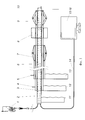
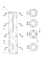
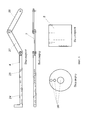
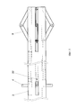
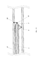
На фиг. 1 приведена структурная схема устройства для обработки бедренной кости (набор хирургических инструментов для обработки костей не показан), на фиг. 2 - схема расположения элементов устройства в канале бедренной кости, на фиг. 3 - конструкция внутренней трубки (ручка не показана, конструкция внешней трубки соответствует конструкции внутренней трубки), на фиг. 4 - конструкция стержня с фиксатором и направителя, на фиг. 5 - фрагмент внутренней трубки с расположенными в ней стержнем и фиксатором, на фиг. 6 - рентгенограмма пациента с нестабильностью ножки эндопротеза, на фиг. 7 - схема перфорации бедренной кости при обработке сверлом, на фиг. 8 - схема расположения элементов устройства в канале бедренной кости и сечения бедренной кости на уровне дистального отдела устройства, на фиг. 9 - схема удаления (фрагментации) костного цемента, на фиг. 10 - схема сверления отверстий из канала бедренной кости. На фиг. 1 приняты следующие обозначения:In FIG. 1 is a structural diagram of a device for treating a femur (a set of surgical instruments for treating bones is not shown), FIG. 2 is a diagram of the arrangement of the elements of the device in the femoral canal; 3 - the construction of the inner tube (the handle is not shown, the design of the outer tube corresponds to the construction of the inner tube), FIG. 4 - the design of the rod with the clamp and the guide, in FIG. 5 is a fragment of an inner tube with a rod and a retainer located in it; FIG. 6 is a radiograph of a patient with instability of the leg of the endoprosthesis, FIG. 7 is a diagram of the perforation of the femur during processing with a drill, in FIG. 8 is a diagram showing the arrangement of device elements in the femoral canal and the femoral section at the level of the distal part of the device, FIG. 9 is a diagram illustrating the removal (fragmentation) of bone cement; FIG. 10 is a diagram of drilling holes from a femoral canal. In FIG. 1 the following notation is accepted:
1 - водяная помпа;1 - water pump;
2 - эндоскоп;2 - endoscope;
3 - внутренняя трубка;3 - an internal tube;
4 - стержень внутренней трубки;4 - the core of the inner tube;
5 - стержень внешней трубки;5 - the core of the outer tube;
6 - внешняя трубка;6 - an external tube;
7 - внешний фиксатор;7 - external clamp;
8 - направитель;8 - a guide;
9 - внутренний фиксатор;9 - internal clamp;
10 - камера эндоскопа;10 - camera endoscope;
11 - ручка эндоскопа;11 - the handle of the endoscope;
12 -ручка внутренней трубки;12 - handle of the inner tube;
13 - ручка внешней трубки;13 - handle of the outer tube;
14 - кабель (световод);14 - cable (optical fiber);
15 - персональный компьютер;15 - personal computer;
16 - канал для инструмента.16 - channel for the tool.
На фиг. 2 приняты следующие обозначения:In FIG. 2 adopted the following notation:
2 - эндоскоп;2 - endoscope;
3 - внутренняя трубка;3 - an internal tube;
6 - внешняя трубка;6 - an external tube;
7 - внешний фиксатор;7 - external clamp;
9 - внутренний фиксатор;9 - internal clamp;
12 -ручка внутренней трубки;12 - handle of the inner tube;
13 - ручка внешней трубки;13 - handle of the outer tube;
17 - бедренная кость;17 - femur;
18 - цементная мантия.18 - cement mantle.
На фиг. 3 приняты следующие обозначения:In FIG. 3 adopted the following notation:
3 - внутренняя трубка;3 - an internal tube;
19 - первый паз трубки;19 - the first groove of the tube;
20 - сквозное отверстие;20 - through hole;
21 - второй паз трубки;21 - the second groove of the tube;
22 - отверстие для крепления фиксатора;22 - hole for fixing the latch;
23 - канал трубки.23 - channel tube.
На фиг. 4 приняты следующие обозначения:In FIG. 4 the following notation is accepted:
4 - стержень внутренней трубки;4 - the core of the inner tube;
7 - фиксатор внутренней трубки;7 - retainer of the inner tube;
8 - направитель;8 - a guide;
24 - шкала;24 - scale;
25 - несквозное отверстие;25 - through hole;
26 - сквозные отверстия направителя;26 - through holes of the guide;
27 - первая пластина;27 - the first plate;
28 - вторая пластина.28 - the second plate.
На фиг. 5 приняты следующие обозначения:In FIG. 5 adopted the following notation:
3 - внутренняя трубка;3 - an internal tube;
4 - стержень внутренней трубки;4 - the core of the inner tube;
9 - внутренний фиксатор.9 - internal latch.
На фиг. 6 приняты следующие обозначения:In FIG. 6 the following notation is accepted:
О - ось бедренной кости;O - axis of the femur;
М - ось ножки эндопротеза.M - axis of the endoprosthesis leg.
На фиг. 7 приняты следующие обозначения:In FIG. 7 the following notation is accepted:
17 - бедренная кость;17 - femur;
18 - цементная мантия;18 - cement mantle;
N - ось инструмента при перфорации бедренной кости.N - axis of the instrument during perforation of the femur.
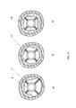
На фиг. 8 приняты следующие обозначения:In FIG. 8 the following notation is accepted:
6 - внешняя трубка;6 - an external tube;
7 - внешний фиксатор;7 - external clamp;
17 - бедренная кость;17 - femur;
18 - цементная мантия.18 - cement mantle.
На фиг. 9 приняты следующие обозначения:In FIG. 9 the following notation is accepted:
2 - эндоскоп;2 - endoscope;
3 - внутренняя трубка;3 - an internal tube;
8 - направитель;8 - a guide;
9 - внутренний фиксатор;9 - internal clamp;
10 - камера эндоскопа;10 - camera endoscope;
17 - бедренная кость;17 - femur;
18 - цементная мантия;18 - cement mantle;
29 - сверло.29 - drill.
На фиг. 10 приняты следующие обозначения:In FIG. 10 the following notation is accepted:
2 - эндоскоп;2 - endoscope;
3 - внутренняя трубка;3 - an internal tube;
9 - внутренний фиксатор;9 - internal clamp;
10 - камера эндоскопа;10 - camera endoscope;
17 - бедренная кость;17 - femur;
30 - сверло с редуктором.30 - drill with gear.
Заявляемое устройство для обработки бедренной кости состоит (см. фиг. 1) из эндоскопа 2 с ручкой эндоскопа 11 и каналами для инструмента 16, соединенного кабелем (световодом) 14 с персональным компьютером 15. Также в его состав входит водяная помпа 1, внешняя трубка 6 с ручкой внешней трубки 13. Внутри внешней трубки 6 находится внутренняя трубка 3 большей длины, чем внешняя, также с ручкой внутренней трубки 12. Внутри внутренней трубки 3 находится эндоскоп 2 таким образом, что ручки внешней трубки 13, внутренней трубки 12 и ручка эндоскопа 11 находятся с одной стороны. При этом внешняя трубка 6 на одном из концов содержит внешний фиксатор 7, внутренняя трубка 3 на одном из концов содержит внутренний фиксатор 9. На внутренней трубке 3 между внутренним фиксатором 9 и внешней трубкой 6 находится направитель 8, выполненный в виде цилиндра с тремя параллельными сквозными отверстиями 26 направителя 8 (фиг. 4), при этом первое отверстие находится в центре цилиндра вдоль его оси и соответствует внутренней трубке 3, центры двух других отверстий 26 расположены вдоль радиуса основания цилиндра. Каждая из трубок 3, 6 содержит два сквозных продольных паза 19, находящиеся с одной стороны каждой из трубок в двух взаимно перпендикулярных плоскостях, линией пересечения которых является ось трубки, два сквозных продольных паза 21 с другой стороны каждой из трубок, расположенные в тех же плоскостях и два сквозных отверстия 20, находящиеся между пазами 19 и 21 в тех же плоскостях перпендикулярно оси трубок (фиг. 3). Внутри стенок каждой из трубок 3, 6 параллельно их оси имеются четыре канала 23, соединяющие продольные пазы 19 и 21 между собой и расположенные в тех же плоскостях, что и пазы 19 и 21 и сквозные отверстия 22 (фиг. 3). Внутри каждого канала 23 каждой из трубок 3 и 6 находится стержень 4 и 5, имеющий в своей средней части перпендикулярные своей оси несквозные отверстия 25, оси которых соответствуют сквозным отверстиям 22 внутренней 3 и внешней 6 трубок (фиг. 4). Один из концов каждого стержня 4 и 5 перпендикулярно изогнут, между изгибом и отверстиями 25 имеет шкалу 24 и выступает из соответствующего продольного паза 19 с одной стороны трубки 3 и 6. Второй конец каждого стержня 4 и 5 подвижно соединен с фиксатором 7 и 9, расположенным в каждом из четырех продольных пазов 21 с другой стороны каждой из трубок 3, 6, причем имеется возможность перемещения каждого стержня 4, 5 со шкалой 24 вдоль соответствующего канала 23 и его фиксации в одном из отверстий 20 соответствующей трубки шпонкой. Каждый фиксатор 7 и 9 состоит из одинаковых первой 27 и второй 28 пластин со сквозными отверстиями на концах, при этом первая пластина 27 подвижно соединена со стержнем 4 со шкалой 24 с одной стороны и со второй пластиной 28 с другой стороны, а вторая пластина 28 подвижно соединена со стенкой трубки 3 и 6 при помощи шпонки, вставленной в отверстие для крепления фиксатора 22, с возможностью выдвижения фиксатора 7 и 9 за пределы соответствующей трубки 3 и 6 при перемещении стержня 4 со шкалой 24 внутрь соответствующего канала 23 в направлении соответствующего фиксатора 7 и 9 и фиксации в выдвинутом положении за счет фиксации стержня 4 со шкалой 24. В состав устройства также входит набор хирургических инструментов для обработки костей.The inventive device for processing the femur consists (see Fig. 1) of an
Составные части заявляемого устройства для обработки бедренной кости могут быть реализованы следующим образом.The components of the claimed device for processing the femur can be implemented as follows.
Водяная помпа 1 представляет собой типовую помпу, применяемую при выполнении артроскопических операций.
Эндоскоп 2 представляет собой жесткий эндоскоп с каналами для инструмента, например, эндоскоп Swiss OrthoClast.
Внешняя и внутренняя трубки 3 и 6 представляют собой металлические трубки, которые могут быть выполнены из медицинской стали.The outer and
Направитель 8 также может быть выполнен из медицинской стали.The
Стержни 4 и 5, элементы фиксаторов 7 и 9 могут быть изготовлены из спиц, аналогичных применяемым в аппарате Илизарова.The
В качестве персонального компьютера 15 может быть использован любой персональный компьютер с установленным программным обеспечением для работы эндоскопа.As a personal computer 15, any personal computer with installed software for operating the endoscope can be used.
Таким образом, реализация заявляемого устройства для обработки бедренной кости не вызывает сомнений, так как для его изготовления используются типовые конструкции, детали, материалы и устройства, применяемые в эндопротезировании и эндоскопии.Thus, the implementation of the inventive device for processing the femur is not in doubt, since for its manufacture typical designs, parts, materials and devices used in arthroplasty and endoscopy are used.
Принцип работы заявляемого устройства рассмотрен на примере ревизионного эндопротезирования при нестабильности ножки протеза и заключается в следующем.The principle of operation of the inventive device is considered as an example of revision arthroplasty with instability of the prosthesis leg and is as follows.
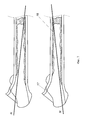
Одним из известных способов, например, передне-латеральным осуществляется доступ к тазобедренному суставу. Удаляют ножку эндопротеза. В случае наличия в канале бедренной кости костного цемента в канал устанавливают эндоскоп 2 с внутренней трубкой 3, внешней трубкой 6, со стержнями 4 и 5, фиксаторами 7 и 9 (далее по тексту - эндоскоп), фиг. 2. Как правило, цементная мантия после удаления ножки содержит так называемую цементную пробку - цемент в области конца ножки эндопротеза (фиг. 2), а также фрагменты цемента на стенках канала (фиг. 9).One of the known methods, for example, antero-lateral, is access to the hip joint. Remove the endoprosthesis leg. If there is bone cement in the femoral canal, an
Для того, чтобы при обработке цементной пробки исключить повреждение кортикального слоя бедренной кости (фиг. 7) за счет неправильного положения инструмента, например, сверла вдоль оси N, эндоскоп вставляют в канал и располагают так, чтобы оно располагалось по центру. Для этого под визуальным контролем перемещают каждый стержень 4 на необходимое расстояние, вдоль соответствующего канала 23, при этом происходит выдвижение соответствующего фиксатора 9. Это позволяет расположить дистальный конец эндоскопа строго по центру канала бедренной кости, т.е. строго по центру цементной пробки. На фиг. 8 представлены варианты расположения дистального конца эндоскопа в зависимости от строения цементной мантии. Выдвижение фиксаторов на различную длину позволяет установить дистальный конец эндоскопа по центру независимо от того, как расположены фрагменты костного цемента на стенках канала бедренной кости, например, на фиг. 8, а) эндоскоп располагается по центру канала при отсутствии костного цемента с одной стороны.In order to eliminate damage to the cortical layer of the femur during the processing of cement plugs (Fig. 7) due to the incorrect position of the instrument, for example, a drill along the N axis, the endoscope is inserted into the channel and positioned so that it is centered. To do this, under visual control each
Выдвижение фиксаторов 5 осуществляется аналогичным образом. Это необходимо для того, чтобы максимально точно позиционировать проксимальную часть эндоскопа относительно оси бедренной кости 17. То есть, для рассверливания цементной пробки эндоскоп устанавливается вдоль оси бедренной кости 17, чтобы обеспечить рассверливание цементной пробки 18, не повредив кортикального слоя кости.The extension of the
Фиксация эндоскопа в необходимом положении осуществляется при помощи шпонок, которые устанавливаются в сквозные отверстия 20 и, соответственно, несквозные отверстия 25. Шкала 24 позволяет оценивать насколько выдвинут соответствующий фиксатор 7 или 9.Fixing the endoscope in the required position is carried out with the help of dowels, which are installed in the through
Рассверливание цементной пробки 18 осуществляется длинным сверлом, устанавливаемым в канал для инструмента 16. Стружка и фрагменты цемента удаляются посредством промывания водяной помпой 1 через каналы для инструмента или просто выливаются наружу.The
Практика ревизионных вмешательств показывает, что при нестабильности ножки эндопротеза, цементная пробка имеет большую прочность, чем окружающая ее бедренная кость 17. При отсутствии жесткой фиксации сверла происходит его «соскальзывание» с цементной пробки и перфорация кости (фиг. 7).The practice of revision interventions shows that in case of instability of the endoprosthesis leg, the cement plug has greater strength than the surrounding
Поскольку выдвижение фиксаторов 7 и 9 осуществляется независимо друг от друга, это позволяет во время операции установить эндоскоп так, как это необходимо хирургу, т.е. не только вдоль оси бедренной кости 17, но и под необходимым углом к оси бедренной кости 17. Поскольку внутренняя трубка имеет возможность поворота относительно внешней трубки, то это позволяет позиционировать эндоскоп не только в сагиттальной плоскости, но и в трехмерном пространстве, т.е. во всех плоскостях так, как это необходимо хирургу во время операции.Since the extension of the
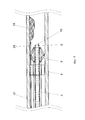
Для удаления фрагментов костного цемента 18, расположенного на стенках бедренной кости 17 на внутреннюю трубку 3 устанавливается направитель 8 (фиг 9). При выполнении вышеперечисленных манипуляций, связанных с удалением цементной пробки он не нужен и может быть снят с внутренней трубки 3. В одно из сквозных отверстий 26 направителя 8 устанавливается длинное сверло. Эндоскоп фиксируется вышеописанным способом в канале бедренной кости 17 в необходимом положении. Далее проводится рассверливание пристеночно расположенного костного цемента 18 под визуальным контролем. Поскольку направитель 8 может вращаться вокруг внутренней трубки 3, то это позволяет рассверлить цемент 18, фиксированный на стенке бедренной кости 17 по всему периметру канала бедренной кости 17.To remove fragments of
В случаях, когда в канале бедренной кости 17 располагаются различные оссификаты, например, когда сформирован «новый» канал бедренной кости 17 (фиг. 6) и ось бедренной кости О не совпадает с ось ножки эндопротеза М, дистальный конец эндоскопа может быть смещен к одному из кортикальных слоев бедренной кости 17 для того, чтобы выполнить разработку канала в необходимом направлении перед установкой новой ножки, чтобы рашпили для обработки не попали в новый, «неправильный» канал.In cases when various ossifications are located in the
Следует отметить, что в каналы для инструмента 16 эндоскопа 2 могут быть установлены любые инструменты, применяемые в эндовидеохирургии, например, зажимы, коагулятор, инструменты для взятия биопсии и другие инструменты для повышения эффективности обработки бедренной кости.It should be noted that in the channels for the tool 16 of the
Обеспечение возможности перемещения эндоскопа перпендикулярно его оси, т.е. от одного кортикального слоя бедренной кости 17 к другому позволит выполнять внутри канала бедренной кости различные манипуляции, например, костную пластику, при истончении кортикального слоя бедренной кости. Она может быть выполнена за счет механического сдавления губчатого костного трансплантата между инструментом, на котором он находится (на ди-стальном конце эндоскопа) и остатками кортикальной кости.Providing the ability to move the endoscope perpendicular to its axis, i.e. from one cortical layer of the
В случае установки на дистальном конце эндоскопа сверла или режущего диска, расположенного перпендикулярно оси эндоскопа, например, сверло с редуктором на фиг. 10, устройство позволяет выполнять интрамедуллярную остеотомию или сверление отверстий в кости непосредственно из канала бедренной кости, что расширяет функциональные возможности прототипа.If a drill or a cutting disc located perpendicular to the axis of the endoscope is installed at the distal end of the endoscope, for example, a drill with a reducer in FIG. 10, the device allows you to perform intramedullary osteotomy or drilling holes in the bone directly from the canal of the femur, which extends the functionality of the prototype.
Техническим результатом заявляемого изобретения является: улучшение качества обработки бедренной кости за счет повышения точности позиционирования инструментов при обработке бедренной кости, расширение функциональных возможностей прототипа.The technical result of the claimed invention is: improving the quality of the processing of the femur by improving the accuracy of positioning of the instruments when processing the femur, expanding the functionality of the prototype.
Claims (1)
Priority Applications (1)
| Application Number | Priority Date | Filing Date | Title |
|---|---|---|---|
| RU2019125840A RU2717706C1 (en) | 2019-08-15 | 2019-08-15 | Device for femoral bone treatment |
Applications Claiming Priority (1)
| Application Number | Priority Date | Filing Date | Title |
|---|---|---|---|
| RU2019125840A RU2717706C1 (en) | 2019-08-15 | 2019-08-15 | Device for femoral bone treatment |
Publications (1)
| Publication Number | Publication Date |
|---|---|
| RU2717706C1 true RU2717706C1 (en) | 2020-03-25 |
Family
ID=69943121
Family Applications (1)
| Application Number | Title | Priority Date | Filing Date |
|---|---|---|---|
| RU2019125840A RU2717706C1 (en) | 2019-08-15 | 2019-08-15 | Device for femoral bone treatment |
Country Status (1)
| Country | Link |
|---|---|
| RU (1) | RU2717706C1 (en) |
Citations (5)
| Publication number | Priority date | Publication date | Assignee | Title |
|---|---|---|---|---|
| RU2583578C1 (en) * | 2014-10-14 | 2016-05-10 | Леонид Карлович Брижань | Device for treatment of cotyloid cavity for hip replacement |
| RU2591534C1 (en) * | 2015-03-05 | 2016-07-20 | Денис Игоревич Варфоломеев | Set for hip replacement |
| WO2016141141A1 (en) * | 2015-03-05 | 2016-09-09 | Trauner Kenneth B | Bone implant augment method and apparatus |
| CN105476701B (en) * | 2015-12-14 | 2018-03-09 | 重庆医科大学附属永川医院 | A kind of bone handling device for femur large segmental bone defect |
| RU2673980C1 (en) * | 2018-05-10 | 2018-12-03 | Денис Игоревич Варфоломеев | Set for hip replacement |
-
2019
- 2019-08-15 RU RU2019125840A patent/RU2717706C1/en active
Patent Citations (5)
| Publication number | Priority date | Publication date | Assignee | Title |
|---|---|---|---|---|
| RU2583578C1 (en) * | 2014-10-14 | 2016-05-10 | Леонид Карлович Брижань | Device for treatment of cotyloid cavity for hip replacement |
| RU2591534C1 (en) * | 2015-03-05 | 2016-07-20 | Денис Игоревич Варфоломеев | Set for hip replacement |
| WO2016141141A1 (en) * | 2015-03-05 | 2016-09-09 | Trauner Kenneth B | Bone implant augment method and apparatus |
| CN105476701B (en) * | 2015-12-14 | 2018-03-09 | 重庆医科大学附属永川医院 | A kind of bone handling device for femur large segmental bone defect |
| RU2673980C1 (en) * | 2018-05-10 | 2018-12-03 | Денис Игоревич Варфоломеев | Set for hip replacement |
Similar Documents
| Publication | Publication Date | Title |
|---|---|---|
| US11172945B1 (en) | Custom radiographically designed cutting guides and instruments for use in total ankle replacement surgery | |
| KR102074133B1 (en) | Suprapatellar insertion system, kit and method | |
| US5624447A (en) | Surgical tool guide and entry hole positioner | |
| US6852115B2 (en) | Multi-functional orthopedic surgical instrument and method of using same | |
| JP2016530958A (en) | Bone removal under direct visualization | |
| JP2023526473A (en) | Devices and techniques for treating metatarsal adduction | |
| US4800873A (en) | Method for setting fractures | |
| RU2717706C1 (en) | Device for femoral bone treatment | |
| Guo et al. | Outcome analysis of intramedullary nailing augmented with poller screws for treating difficult reduction fractures of femur and tibia: a retrospective cohort study | |
| JP2013517918A (en) | Implementation system for bone marrow endoscopy | |
| RU2611897C1 (en) | Method of excision of femoral component of hip joint endoprosthesis | |
| KR100771677B1 (en) | Osteosynthetic device | |
| RU2614496C2 (en) | Sighting device for hidden screw removal from femoral shaft | |
| CN213310237U (en) | Reduction device for minimally invasive auxiliary reduction of tibial plateau fracture under monitoring of arthroscope | |
| RU153331U1 (en) | DEVICE FOR INTRAMEDULAR OSTEOSYNTHESIS OF THE TIBERA | |
| WO1999012485A1 (en) | Creating holes in bone via the medullary cavity | |
| EP1890617A2 (en) | Fixator | |
| RU166284U1 (en) | INTRAMEDULAR BLOCKING DEVICE FOR OSTEOSYNTHESIS OF FEMOR FRACTURES | |
| Buehler et al. | Polymethylmethacrylate removal from the femur using a crescentic window technique | |
| RU2799129C1 (en) | Method of distal blocking of intramedullary implants | |
| RU2583578C1 (en) | Device for treatment of cotyloid cavity for hip replacement | |
| RU2252723C1 (en) | Distal locking method for fixing cannulated rods in performing intramedullary osteosynthesis of long tubular bones | |
| Vita et al. | A new technique for cement plug removal in hip and knee arthoplasty exchange | |
| RU2737334C9 (en) | Device for removing bone or cement plug from femoral canal in revision hip endoprosthesis replacement surgery | |
| RU2210331C2 (en) | Method for surgical treatment of brachial collum fractures |