RU2715744C2 - Rotary switch for use in unfavorable ambient conditions - Google Patents
Rotary switch for use in unfavorable ambient conditions Download PDFInfo
- Publication number
- RU2715744C2 RU2715744C2 RU2016144437A RU2016144437A RU2715744C2 RU 2715744 C2 RU2715744 C2 RU 2715744C2 RU 2016144437 A RU2016144437 A RU 2016144437A RU 2016144437 A RU2016144437 A RU 2016144437A RU 2715744 C2 RU2715744 C2 RU 2715744C2
- Authority
- RU
- Russia
- Prior art keywords
- switch
- housing
- insert
- socket
- metal
- Prior art date
Links
Images
Classifications
-
- H—ELECTRICITY
- H01—ELECTRIC ELEMENTS
- H01H—ELECTRIC SWITCHES; RELAYS; SELECTORS; EMERGENCY PROTECTIVE DEVICES
- H01H19/00—Switches operated by an operating part which is rotatable about a longitudinal axis thereof and which is acted upon directly by a solid body external to the switch, e.g. by a hand
- H01H19/02—Details
- H01H19/04—Cases; Covers
- H01H19/06—Dustproof, splashproof, drip-proof, waterproof, or flameproof casings
-
- H—ELECTRICITY
- H01—ELECTRIC ELEMENTS
- H01H—ELECTRIC SWITCHES; RELAYS; SELECTORS; EMERGENCY PROTECTIVE DEVICES
- H01H19/00—Switches operated by an operating part which is rotatable about a longitudinal axis thereof and which is acted upon directly by a solid body external to the switch, e.g. by a hand
- H01H19/02—Details
- H01H19/08—Bases; Stationary contacts mounted thereon
-
- H—ELECTRICITY
- H01—ELECTRIC ELEMENTS
- H01H—ELECTRIC SWITCHES; RELAYS; SELECTORS; EMERGENCY PROTECTIVE DEVICES
- H01H11/00—Apparatus or processes specially adapted for the manufacture of electric switches
-
- F—MECHANICAL ENGINEERING; LIGHTING; HEATING; WEAPONS; BLASTING
- F16—ENGINEERING ELEMENTS AND UNITS; GENERAL MEASURES FOR PRODUCING AND MAINTAINING EFFECTIVE FUNCTIONING OF MACHINES OR INSTALLATIONS; THERMAL INSULATION IN GENERAL
- F16B—DEVICES FOR FASTENING OR SECURING CONSTRUCTIONAL ELEMENTS OR MACHINE PARTS TOGETHER, e.g. NAILS, BOLTS, CIRCLIPS, CLAMPS, CLIPS OR WEDGES; JOINTS OR JOINTING
- F16B5/00—Joining sheets or plates, e.g. panels, to one another or to strips or bars parallel to them
- F16B5/02—Joining sheets or plates, e.g. panels, to one another or to strips or bars parallel to them by means of fastening members using screw-thread
-
- H—ELECTRICITY
- H01—ELECTRIC ELEMENTS
- H01H—ELECTRIC SWITCHES; RELAYS; SELECTORS; EMERGENCY PROTECTIVE DEVICES
- H01H13/00—Switches having rectilinearly-movable operating part or parts adapted for pushing or pulling in one direction only, e.g. push-button switch
- H01H13/02—Details
- H01H13/04—Cases; Covers
- H01H13/06—Dustproof, splashproof, drip-proof, waterproof or flameproof casings
-
- H—ELECTRICITY
- H01—ELECTRIC ELEMENTS
- H01H—ELECTRIC SWITCHES; RELAYS; SELECTORS; EMERGENCY PROTECTIVE DEVICES
- H01H19/00—Switches operated by an operating part which is rotatable about a longitudinal axis thereof and which is acted upon directly by a solid body external to the switch, e.g. by a hand
- H01H19/02—Details
- H01H19/04—Cases; Covers
-
- H—ELECTRICITY
- H01—ELECTRIC ELEMENTS
- H01H—ELECTRIC SWITCHES; RELAYS; SELECTORS; EMERGENCY PROTECTIVE DEVICES
- H01H19/00—Switches operated by an operating part which is rotatable about a longitudinal axis thereof and which is acted upon directly by a solid body external to the switch, e.g. by a hand
- H01H19/02—Details
- H01H19/10—Movable parts; Contacts mounted thereon
- H01H19/11—Movable parts; Contacts mounted thereon with indexing means
-
- H—ELECTRICITY
- H01—ELECTRIC ELEMENTS
- H01H—ELECTRIC SWITCHES; RELAYS; SELECTORS; EMERGENCY PROTECTIVE DEVICES
- H01H21/00—Switches operated by an operating part in the form of a pivotable member acted upon directly by a solid body, e.g. by a hand
-
- H—ELECTRICITY
- H01—ELECTRIC ELEMENTS
- H01H—ELECTRIC SWITCHES; RELAYS; SELECTORS; EMERGENCY PROTECTIVE DEVICES
- H01H2219/00—Legends
- H01H2219/028—Printed information
-
- H—ELECTRICITY
- H01—ELECTRIC ELEMENTS
- H01H—ELECTRIC SWITCHES; RELAYS; SELECTORS; EMERGENCY PROTECTIVE DEVICES
- H01H2223/00—Casings
- H01H2223/008—Casings metallic
-
- H—ELECTRICITY
- H01—ELECTRIC ELEMENTS
- H01H—ELECTRIC SWITCHES; RELAYS; SELECTORS; EMERGENCY PROTECTIVE DEVICES
- H01H2229/00—Manufacturing
-
- H—ELECTRICITY
- H01—ELECTRIC ELEMENTS
- H01H—ELECTRIC SWITCHES; RELAYS; SELECTORS; EMERGENCY PROTECTIVE DEVICES
- H01H2239/00—Miscellaneous
- H01H2239/034—Environmental protection
Landscapes
- Engineering & Computer Science (AREA)
- Manufacturing & Machinery (AREA)
- General Engineering & Computer Science (AREA)
- Mechanical Engineering (AREA)
- Rotary Switch, Piano Key Switch, And Lever Switch (AREA)
- Switch Cases, Indication, And Locking (AREA)
- Switches That Are Operated By Magnetic Or Electric Fields (AREA)
Abstract
Description
Изобретение относится к поворотному выключателю, снабженному средством визуальной сигнализации, в частности, пригодному для эксплуатации в неблагоприятных условиях окружающей среды.The invention relates to a rotary switch equipped with a visual alarm, in particular, suitable for use in adverse environmental conditions.
В частности, поворотный выключатель снабжен средством сигнализации, таким как индикатор состояния, для обеспечения визуальной индикации рабочего состояния приводного устройства, такого как клапан или привод, функционально связанного с указанным выключателем. Поворотный выключатель такого типа, оснащенный средством визуальной сигнализации, обычно называют "ограничительным выключателем" (ОВ).In particular, the rotary switch is provided with an alarm means, such as a status indicator, to provide a visual indication of the operating state of the drive device, such as a valve or actuator, functionally associated with the switch. This type of rotary switch equipped with a visual alarm is commonly referred to as a "limit switch" (OB).
Ограничительные выключатели известного уровня техники, как правило, содержат корпус и крышку, а также установленный внутри вращающийся элемент или индикатор, функционально связанный с валом клапана или привода, расположенного в корпусе. Вращающиеся элементы часто оснащены визуальными индикаторами углового положения вала клапана или привода, с целью обеспечения визуальной индикации с внешней стороны выключателя рабочего состояния клапана или привода. Эти визуальные индикаторы обычно размещены на крышке, чтобы их можно было видеть снаружи выключателя; например, индикатор может быть выполнен в виде диска или колпачка, вращающегося совместно с валом и снабженного соединенным с ним закрывающим элементом, который является зафиксированным и выполняет функцию фиксированной базы углового положения индикатора.Prior art limit switches typically include a housing and a cover, as well as a rotating element or indicator mounted internally that is operatively coupled to a valve or actuator shaft located within the housing. Rotating elements are often equipped with visual indicators of the angular position of the valve or actuator shaft, in order to provide a visual indication on the outside of the valve or actuator operating status switch. These visual indicators are usually located on the cover so that they can be seen from the outside of the switch; for example, the indicator can be made in the form of a disk or cap rotating together with the shaft and equipped with a closing element connected to it, which is fixed and performs the function of a fixed base of the angular position of the indicator.
Ограничительные выключатели часто применяются в области добычи и переработки углеводородов, например, в нефтяных скважинах, на морских буровых платформах и трубопроводах. В установках такого типа высокое содержание двуокиси углерода и сероводорода в неочищенной нефти и газе, в сочетании с неблагоприятными условиями окружающей среды (например, в открытом море или в пустыне), может приводить к серьезным коррозионным явлениям.Limit switches are often used in the field of hydrocarbon production and processing, for example, in oil wells, on offshore drilling platforms and pipelines. In plants of this type, the high content of carbon dioxide and hydrogen sulfide in crude oil and gas, combined with adverse environmental conditions (for example, on the high seas or in the desert), can lead to serious corrosion phenomena.
Типичным примером является гальвано-контактная коррозия, возникающая в ситуации, когда один металл находится в электрическом контакте с другим электрохимически неактивным металлом (фактически, для возникновения коррозии часто бывает достаточно лишь механического контакта одного металла с другим), и оба металла подвержены воздействию неблагоприятной окружающей среды (например, в присутствии морской воды или кислых растворов). В результате такой коррозии происходит медленное и постепенное окисление электрохимически более активного металла. Кроме того, в случае комбинированного действия механических напряжений и коррозионно-активной среды, часто возникают трещины в металле, которые могут приводить к выходу из строя металлических деталей.A typical example is galvanic contact corrosion, which occurs when one metal is in electrical contact with another electrochemically inactive metal (in fact, it is often only mechanical contact of one metal with another that is sufficient to cause corrosion), and both metals are exposed to adverse environmental conditions. (for example, in the presence of sea water or acidic solutions). As a result of such corrosion, a slow and gradual oxidation of the electrochemically more active metal occurs. In addition, in the case of the combined action of mechanical stresses and a corrosive medium, cracks in the metal often occur, which can lead to the failure of metal parts.
Даже ограничительные выключатели, изготовляемые, в основном, из металла, при эксплуатации в неблагоприятных условиях окружающей среды подвержены коррозии вышеупомянутого типа, которая может приводить к их выходу из строя. Это обуславливает высокие затраты на ликвидацию как непосредственных повреждений (замена поврежденных материалов, затраты на проведение операций замены), так и косвенных убытков (производственные потери, простой оборудования, загрязнение окружающей среды).Even limit switches made mainly of metal, when operated in adverse environmental conditions, are susceptible to corrosion of the aforementioned type, which can lead to their failure. This leads to high costs for the elimination of both direct damage (replacement of damaged materials, the cost of replacement operations), and indirect losses (production losses, downtime of equipment, environmental pollution).
В связи с вышесказанным, области промышленности, оборудование в которых работает в неблагоприятных условиях окружающей среды, нуждаются в высоконадежных устройствах, обеспечивающих низкие затраты на техобслуживание.In connection with the foregoing, industries in which equipment operates in adverse environmental conditions require highly reliable devices that provide low maintenance costs.
Таким образом, существует необходимость в создании поворотного выключателя, стойкого к воздействию коррозии.Thus, there is a need for a rotary switch that is resistant to corrosion.
Данная цель достигается с помощью поворотного выключателя по п. 1 формулы настоящего изобретения и с помощью соответствующего способа изготовления по п. 9.This goal is achieved using the rotary switch according to claim 1 of the claims of the present invention and using the corresponding manufacturing method according to claim 9.
В зависимых пунктах формулы представлены также другие варианты реализации выключателя согласно настоящему изобретению.Other dependent embodiments of the circuit breaker according to the present invention are also presented in the dependent claims.
Дальнейшие характеристики и преимущества настоящего изобретения станут более понятными после ознакомления с приведенным ниже его подробным описанием на примере предпочтительного и не ограничивающего варианта реализации со ссылками на прилагаемые чертежи, на которых:Further characteristics and advantages of the present invention will become more apparent after reading the following detailed description on the example of a preferred and non-limiting implementation with reference to the accompanying drawings, in which:
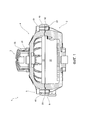
на фиг. 1 - поворотный выключатель согласно настоящему изобретению, вид сбоку в разрезе;in FIG. 1 - rotary switch according to the present invention, a side view in section;
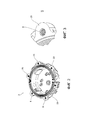
на фиг. 2 - корпус поворотного выключателя, показанного на фиг. 1, вид в перспективе;in FIG. 2 - housing of the rotary switch shown in FIG. 1 is a perspective view;
на фиг. 3 - элемента корпуса, показанного на фиг. 2, вид в увеличенном масштабе;in FIG. 3 - housing element shown in FIG. 2 is an enlarged view;
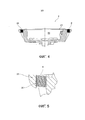
на фиг. 4 - корпус, показанный на фиг. 2, вид сбоку в разрезе;in FIG. 4 - the housing shown in FIG. 2 is a sectional side view;
на фиг. 5 - элемент корпуса, показанного на фиг. 5, вид в увеличенном масштабе.in FIG. 5 is an element of the housing shown in FIG. 5 is an enlarged view.
На указанных выше чертежах ссылочной позицией 1 обозначен поворотный выключатель в целом, оснащенный средством визуальной сигнализации для визуальной индикации рабочего состояния внешнего устройства.In the above drawings, reference numeral 1 denotes a rotary switch as a whole, equipped with visual signaling means for visually indicating the operating state of an external device.
Поворотный выключатель 1 содержит корпус 2 выключателя с расположенным внутри валом (не показан), который может вращаться относительно оси вращения Х-Х в зависимости от работы внешнего устройства.The rotary switch 1 comprises a
Корпус 2 выключателя выполнен из металла или покрыт снаружи металлом. Например, корпус 2 выключателя может быть выполнен из алюминия или алюминиевых сплавов.The
Что касается формы, количество стенок и геометрические размеры корпуса 2 выключателя могут быть любыми, и их ни в коем случае не следует считать ограничивающими объем настоящего изобретения.As for the shape, the number of walls and the geometric dimensions of the
.Корпус 2 выключателя содержит отверстие 21 для доступа во внутреннюю полость 22, в которой установлен вал с возможностью вращения.The
Корпус 2 выключателя содержит расположенную на отверстии 21 кромку 23, выступающую наружу.The
Поворотный выключатель 1 также включает в себя крышку 4, надеваемую на корпус 2 выключателя для его закрытия, содержащую средство 3 визуальной сигнализации, установленное на валу с возможностью вращения относительно оси Х-Х.The rotary switch 1 also includes a
Предпочтительно, крышка 4 выполнена из металла или покрыта снаружи металлом.Preferably, the
Крышка 4 содержит отверстие для доступа во внутреннюю полость 42, в которой установлен вал с возможностью вращения.The
Крышка 4 содержит расположенную на отверстии 21 кромку 43, выступающую наружу.The
Предпочтительно, средство 3 визуальной сигнализации содержит индикатор 31, прикрепленный с возможностью вращения к указанному валу 20 с целью обеспечения визуальной сигнализации углового положения и/или рабочего состояния вращающегося вала при взгляде снаружи поворотного выключателя 1.Preferably, the visual signaling means 3 comprises an
Согласно одному из возможных вариантов реализации, индикатор 31 может вращаться относительно указанной оси вращения Х-Х, и может быть снабжен крышкой 32 для обеспечения возможности визуальной сигнализации рабочего состояния внешнего устройства. Например, крышка 32 может выполнять функцию закрывающего средства, обеспечивая быструю и эффективную идентификацию рабочего состояния внешнего устройства; например, крышка 32 может содержать закрытые области, а индикатор 31 может содержать сигнализацию рабочего состояния, например, текст "открыто-закрыто".According to one possible implementation, the
Индикация рабочего состояния внешнего устройства демонстрируется на индикаторе 31, функционально связанном с валом, причем данная индикация может производиться механическим, химическим или электрохимическим способом, а также посредством демонстрации обозначений.Indication of the operating state of the external device is shown on the
Крышка 4 прикреплена к корпусу 2 выключателя с целью его закрытия с помощью нескольких соединительных винтов 5, каждый из которых расположен в специальном гнезде 45, 25, выполненном как в крышке 4, так и в корпусе 2 выключателя.The
Предпочтительно, корпус 2 выключателя содержит на кромке 23 несколько таких гнезд 25. Кроме того, крышка 4, предпочтительно, также содержит на кромке 43 определенное количество гнезд 45, расположенных таким образом, что они совпадают с гнездами 25 корпуса 2 выключателя.Preferably, the
Гнездо 25, выполненное в корпусе 2 выключателя, представляет собой резьбовое отверстие. Предпочтительно, гнездо 25 представляет собой сквозное резьбовое отверстие.
Предпочтительно, гнездо 45, выполненное в крышке 4, в своей первой части представляет собой сквозное резьбовое отверстие, чтобы обеспечивалась возможность закрепления винта.Preferably, the
Соединительные винты 5 выполнены из металла или покрыты снаружи металлом. Например, соединительные винты 5 могут быть выполнены из стали, предпочтительно, нержавеющей стали.The connecting
Соединительный винт 5 содержит головку 51 и резьбовой конец 52. Предпочтительно, соединительные винты 5 представляют собой болты с квадратной головкой.The connecting
Даже в обычном поворотном выключателе крышка крепится к корпусу выключателя с помощью нескольких винтов. Следует отметить, что корпус и винты выполнены из разных металлических материалов, в частности, корпус обычно выполняется из более химически активного металла. Таким образом, при использовании обычного поворотного выключателя в неблагоприятных условиях окружающей среды, т.е., когда он подвержен воздействию неблагоприятных условий, простой механический контакт металлических поверхностей корпуса и винтов приводит к возникновению коррозии вследствие гальванического контакта. Такая коррозия приводит к образованию ржавчины, которая прочно скрепляет винт с резьбовым отверстием, делая невозможным его отворачивание и вскрытие обычного поворотного выключателя для проведения операций техобслуживания. Кроме того, коррозия, в сочетании с действующими на корпус механическими напряжениями вследствие затяжки винтов, приводит к образованию трещин в металле корпуса, что служит причиной выхода из строя обычного поворотного выключателя.Even in a conventional rotary switch, the cover is attached to the switch housing with a few screws. It should be noted that the case and screws are made of different metal materials, in particular, the case is usually made of a more reactive metal. Thus, when using a conventional rotary switch in adverse environmental conditions, i.e. when it is exposed to adverse conditions, a simple mechanical contact of the metal surfaces of the housing and screws leads to corrosion due to galvanic contact. Such corrosion leads to the formation of rust, which firmly fastens the screw with the threaded hole, making it impossible to open it and open the conventional rotary switch for maintenance operations. In addition, corrosion, in combination with mechanical stresses acting on the housing due to the tightening of the screws, leads to the formation of cracks in the metal of the housing, which causes the failure of a conventional rotary switch.
С учетом вышесказанного, в поворотном выключателе 1 согласно настоящему изобретению, внутри гнезда 25 в корпусе 2 выключателя предусмотрена вставка 6.In view of the foregoing, in the rotary switch 1 according to the present invention, an
Вставка 6 представляет собой цилиндрический элемент (например, гильзу) с резьбой на внешней поверхности для присоединения к резьбовой поверхности гнезда 25, и с резьбой на внутренней поверхности для вкручивания соединительного винта, входящего в зацепление с указанной внутренней резьбой.The
Предпочтительно, вставка 6 выполнена из материала, способного предотвратить возникновение гальванического тока между гнездом 25 корпуса 2 выключателя и соединительным винтом 5.Preferably, the
В одном из вариантов реализации изобретения, вставка 6 выполнена из того же самого материала, что и соединительный винт 5, и, таким образом, между вставкой и соединительным винтом коррозия не возникает. В этом примере, вставка 6 выполнена из менее химически активного металла, чем корпус 2 выключателя; таким образом, между корпусом и вставкой коррозия не возникает. Однако возможное образование оксидов между корпусом и вставкой, которые также скрепляют эти два элемента, не мешает проведению операций техобслуживания на поворотном выключателе 1 согласно настоящему изобретению. В данном варианте реализации, вставка 6 дает возможность "перенесения" явления коррозии с пары корпус-винт на пару корпус-вставка.In one embodiment of the invention, the
В варианте реализации, в котором корпус 2 выключателя выполнен из алюминия или алюминиевого сплава, а соединительный винт 5 выполнен из стали, ставка 6 может быть выполнена, например, из стали, предпочтительно, из нержавеющей стали.In an embodiment in which the
В еще одном возможном варианте реализации, вставка 6 выполнена из изолирующего материала или покрыта изолирующим материалом, и, следовательно, между вставкой и соединительным винтом коррозия не возникает. Это дает возможность предотвратить распространение микротоков и коррозию более химически активного из двух металлов. Таким образом, в данном примере вставка 6 способна электрически изолировать два металла и предотвращать возникновение электротоков между ними. Следовательно, вставка 6 дает возможность предотвратить возникновение коррозии между корпусом и вставкой, а также между вставкой и винтом.In yet another possible embodiment, the
В варианте реализации, в котором корпус 2 выключателя выполнен из алюминия или алюминиевого сплава, а соединительный винт 5 выполнен из стали, ставка 6 может быть выполнена, например, из стали с покрытием из изолирующего материала или заряженного пластика.In an embodiment in which the
Объектом настоящего изобретения также является способ изготовления поворотного выключателя 1 с крышкой 4, прикрепляемой к корпусу 2 выключателя для его закрытия с помощью нескольких соединительных винтов, каждый из которых установлен в специальном гнезде 45, 25 выполненном в крышке 4 и корпусе 2 выключателя. В частности, вышеуказанный способ включает в себя следующие этапы:The object of the present invention is also a method of manufacturing a rotary switch 1 with a
- обеспечение наличия корпуса 2 выключателя, выполненного из металла или покрытого снаружи металлом;- ensuring the presence of the
- выполнение гнезда 25 в корпусе 2 выключателя;- the implementation of the
- установку внутрь гнезда 25 вставки 6, выполненной из материала, предотвращающего возникновение гальванических токов между гнездом 25 корпуса 2 выключателя и соединительным винтом 5.- installation inside the
В частности, этап выполнения гнезда 25 включает в себя выполнение резьбового отверстия в корпусе 2 выключателя, а этап установки вставки 6 предполагает вкручивание вставки 6 с внутренней и наружной резьбовыми поверхностями в указанное резьбовое отверстие в корпусе 2 выключателя.In particular, the execution phase of the
Поворотный выключатель 1 согласно настоящему изобретению является коррозионно-стойким, и, в частности, может быть использован при неблагоприятных условиях окружающей среды (например, на нефтепромысловых платформах в открытом море или нефтедобывающих скважинах в пустыне).The rotary switch 1 according to the present invention is corrosion resistant, and, in particular, can be used under adverse environmental conditions (for example, on oil fields on the high seas or oil wells in the desert).
Преимущество настоящего изобретения заключается в том, что поворотный выключатель 1 согласно настоящему изобретению со вставкой 6 между резьбовым отверстием гнезда 25 корпуса 2 выключателя и соединительным винтом 5 не подвержен возникновению коррозии между корпусом и винтом.An advantage of the present invention is that the rotary switch 1 according to the present invention with an
Специалисты в данной области без труда увидят множество других возможных изменений и модификаций конструкции вышеописанного поворотного выключателя, отвечающих конкретным требованиям и не выходящих за рамки объема охраны настоящего изобретения, определяемые приведенной ниже формулой изобретения.Specialists in this field will easily see many other possible changes and modifications to the design of the above-described rotary switch that meet specific requirements and do not go beyond the scope of protection of the present invention defined by the following claims.
Claims (10)
Applications Claiming Priority (2)
| Application Number | Priority Date | Filing Date | Title |
|---|---|---|---|
| IT102015000071969 | 2015-11-12 | ||
| ITUB2015A005510A ITUB20155510A1 (en) | 2015-11-12 | 2015-11-12 | ROTARY SWITCH SUITABLE FOR USE IN ADVERSE ENVIRONMENTAL CONDITIONS |
Publications (3)
| Publication Number | Publication Date |
|---|---|
| RU2016144437A RU2016144437A (en) | 2018-05-11 |
| RU2016144437A3 RU2016144437A3 (en) | 2020-02-11 |
| RU2715744C2 true RU2715744C2 (en) | 2020-03-03 |
Family
ID=55446957
Family Applications (1)
| Application Number | Title | Priority Date | Filing Date |
|---|---|---|---|
| RU2016144437A RU2715744C2 (en) | 2015-11-12 | 2016-11-11 | Rotary switch for use in unfavorable ambient conditions |
Country Status (9)
| Country | Link |
|---|---|
| US (2) | US20170140885A1 (en) |
| EP (1) | EP3168853B1 (en) |
| KR (1) | KR20170055912A (en) |
| CN (1) | CN106935436A (en) |
| AU (1) | AU2016253708A1 (en) |
| BR (1) | BR102016026383A2 (en) |
| IT (1) | ITUB20155510A1 (en) |
| RU (1) | RU2715744C2 (en) |
| SG (1) | SG10201609308WA (en) |
Families Citing this family (2)
| Publication number | Priority date | Publication date | Assignee | Title |
|---|---|---|---|---|
| ITBS20130139A1 (en) * | 2013-10-07 | 2015-04-08 | Soldo S R L Socio Unico | EXPLOSION-PROOF ROTARY SWITCH, EQUIPPED WITH VISUAL REPORTING MEANS AND MEANS OF CONTROL |
| KR102756190B1 (en) * | 2019-10-22 | 2025-01-17 | 삼성전자주식회사 | Integrated circuit device and method of manufacturing the same |
Citations (6)
| Publication number | Priority date | Publication date | Assignee | Title |
|---|---|---|---|---|
| RU2143140C1 (en) * | 1998-05-19 | 1999-12-20 | Военная академия связи | Shift register |
| RU2318266C1 (en) * | 2006-11-16 | 2008-02-27 | Открытое акционерное общество "Дивногорский завод низковольтных автоматов" (ОАО "Дивногорский завод низковольтных автоматов") | Automatic circuit breaker |
| RU2393576C1 (en) * | 2008-12-22 | 2010-06-27 | Открытое акционерное общество "Контактор" | Automatic switch |
| WO2014002003A1 (en) * | 2012-06-28 | 2014-01-03 | Emer S.P.A. | Fluid flow regulating device, particularly for automotive gas systems, having high resistance to corrosion |
| EP2869325A1 (en) * | 2013-10-31 | 2015-05-06 | Soldo S.r.l. Socio Unico | Universal connection system of a rotary switch with a linear actuator |
| RU154885U1 (en) * | 2015-01-14 | 2015-09-10 | Закрытое акционерное общество "Производственное объединение Электротехник" | WAY SWITCH |
Family Cites Families (8)
| Publication number | Priority date | Publication date | Assignee | Title |
|---|---|---|---|---|
| US5029051A (en) * | 1989-04-17 | 1991-07-02 | Koito Manufacturing Co., Ltd. | Headlamp for motor vehicles |
| US5047599A (en) * | 1990-03-23 | 1991-09-10 | Giolli Donald A | Locking housing for a switch |
| JP3606932B2 (en) * | 1994-12-30 | 2005-01-05 | 石福金属興業株式会社 | Electrode composite electrode |
| US7214895B2 (en) * | 2004-07-01 | 2007-05-08 | Rockwell Automation Technologies, Inc. | Illuminated disconnecting handle for use with CDM |
| CN2789912Y (en) * | 2005-03-11 | 2006-06-21 | 贺颖 | Knob switch |
| US8375883B2 (en) * | 2007-12-12 | 2013-02-19 | Soldo S.R.L. Socio Unico | Rotary switch and relative assembly method |
| CN202285258U (en) * | 2011-11-01 | 2012-06-27 | 中国电子科技集团公司第十八研究所 | Protection device of steel wire screw sleeve internally embedded in aluminum alloy battery cover body |
| CN204537907U (en) * | 2015-03-28 | 2015-08-05 | 鞍钢股份有限公司 | Waterproof corrosion-resistant button switch box |
-
2015
- 2015-11-12 IT ITUB2015A005510A patent/ITUB20155510A1/en unknown
-
2016
- 2016-10-20 EP EP16194881.5A patent/EP3168853B1/en not_active Not-in-force
- 2016-11-07 AU AU2016253708A patent/AU2016253708A1/en not_active Abandoned
- 2016-11-07 SG SG10201609308WA patent/SG10201609308WA/en unknown
- 2016-11-08 KR KR1020160148114A patent/KR20170055912A/en not_active Withdrawn
- 2016-11-10 BR BR102016026383A patent/BR102016026383A2/en not_active Application Discontinuation
- 2016-11-11 RU RU2016144437A patent/RU2715744C2/en active
- 2016-11-11 CN CN201610997733.6A patent/CN106935436A/en active Pending
- 2016-11-14 US US15/350,106 patent/US20170140885A1/en not_active Abandoned
-
2019
- 2019-12-13 US US16/713,352 patent/US20200118774A1/en not_active Abandoned
Patent Citations (6)
| Publication number | Priority date | Publication date | Assignee | Title |
|---|---|---|---|---|
| RU2143140C1 (en) * | 1998-05-19 | 1999-12-20 | Военная академия связи | Shift register |
| RU2318266C1 (en) * | 2006-11-16 | 2008-02-27 | Открытое акционерное общество "Дивногорский завод низковольтных автоматов" (ОАО "Дивногорский завод низковольтных автоматов") | Automatic circuit breaker |
| RU2393576C1 (en) * | 2008-12-22 | 2010-06-27 | Открытое акционерное общество "Контактор" | Automatic switch |
| WO2014002003A1 (en) * | 2012-06-28 | 2014-01-03 | Emer S.P.A. | Fluid flow regulating device, particularly for automotive gas systems, having high resistance to corrosion |
| EP2869325A1 (en) * | 2013-10-31 | 2015-05-06 | Soldo S.r.l. Socio Unico | Universal connection system of a rotary switch with a linear actuator |
| RU154885U1 (en) * | 2015-01-14 | 2015-09-10 | Закрытое акционерное общество "Производственное объединение Электротехник" | WAY SWITCH |
Also Published As
| Publication number | Publication date |
|---|---|
| AU2016253708A1 (en) | 2017-06-01 |
| US20200118774A1 (en) | 2020-04-16 |
| RU2016144437A (en) | 2018-05-11 |
| KR20170055912A (en) | 2017-05-22 |
| EP3168853B1 (en) | 2018-09-12 |
| ITUB20155510A1 (en) | 2017-05-12 |
| BR102016026383A2 (en) | 2017-05-23 |
| RU2016144437A3 (en) | 2020-02-11 |
| EP3168853A1 (en) | 2017-05-17 |
| US20170140885A1 (en) | 2017-05-18 |
| CN106935436A (en) | 2017-07-07 |
| SG10201609308WA (en) | 2017-06-29 |
Similar Documents
| Publication | Publication Date | Title |
|---|---|---|
| CN106992415A (en) | A kind of liquid metal high speed rotary electric connector and its design method | |
| WO2015113021A1 (en) | Lid sensor and retrofit system | |
| US20200118774A1 (en) | Rotary Switch Suitable For Use In Adverse Environmental Conditions | |
| KR102534340B1 (en) | Electrical Bushing with Anti-Rotation Mounting Flange and Mounting Method Thereof | |
| KR200254149Y1 (en) | electric potential test box for gas pipe | |
| CN108823571A (en) | A kind of intelligent seawaterline sacrificial anode structure having criticality alarm function and its etch state in-situ monitoring method | |
| CN103205761A (en) | Pipe clamp type sacrificial anode installation device free from underwater welding | |
| CN111555747B (en) | Proximity switches | |
| CN104577424A (en) | Special signal wiring terminal for closed-type ammonium-resistant refrigerating compressor | |
| CN210830681U (en) | Explosion-proof electric ball valve protection device | |
| GB2072853A (en) | Electrode probe assemblies | |
| CN104124010A (en) | Insulator and gas insulated metal-enclosed switchgear | |
| CN207233646U (en) | A kind of detachable switch insulation casing | |
| CN210868466U (en) | Waterproof component of compressor electrical box and compressor | |
| JP3516714B2 (en) | Communication equipment housing | |
| CN215626969U (en) | Antifouling anticorrosive electrode | |
| CN223598568U (en) | Automatic short-circuit switch of full-sea deep underwater equipment | |
| US4617511A (en) | Electrode probe assembly for glass lined metal vessels | |
| CN220873388U (en) | Hardware terminal with good corrosion resistance for transformer | |
| CN206770375U (en) | A kind of lead sealing internal lead sealing screw | |
| AU777084B2 (en) | Resistance controlled sacrificial anode | |
| CN221275896U (en) | Oil pipe sacrificial anode anti-corrosion device | |
| CN114524063B (en) | Method for replacing marine water gate set and ship | |
| CN223331134U (en) | Shafting waterproof sleeve of standard ship type and ship | |
| CN212463771U (en) | An explosion-proof and anti-corrosion master controller |
Legal Events
| Date | Code | Title | Description |
|---|---|---|---|
| HZ9A | Changing address for correspondence with an applicant | ||
| HE9A | Changing address for correspondence with an applicant |