RU2709099C2 - Lighting device with wireless communication antenna - Google Patents
Lighting device with wireless communication antenna Download PDFInfo
- Publication number
- RU2709099C2 RU2709099C2 RU2018111248A RU2018111248A RU2709099C2 RU 2709099 C2 RU2709099 C2 RU 2709099C2 RU 2018111248 A RU2018111248 A RU 2018111248A RU 2018111248 A RU2018111248 A RU 2018111248A RU 2709099 C2 RU2709099 C2 RU 2709099C2
- Authority
- RU
- Russia
- Prior art keywords
- antenna
- light sources
- gas
- pumping tube
- filled lamp
- Prior art date
Links
- 238000004891 communication Methods 0.000 title abstract description 3
- 238000005086 pumping Methods 0.000 claims abstract description 43
- 238000004519 manufacturing process Methods 0.000 claims abstract description 10
- 238000000034 method Methods 0.000 claims description 10
- 244000052769 pathogen Species 0.000 claims description 9
- 230000001717 pathogenic effect Effects 0.000 claims description 9
- 239000007787 solid Substances 0.000 claims description 8
- 238000000149 argon plasma sintering Methods 0.000 claims description 4
- 230000000694 effects Effects 0.000 abstract description 4
- 238000009434 installation Methods 0.000 abstract 1
- 239000000126 substance Substances 0.000 abstract 1
- 239000007789 gas Substances 0.000 description 12
- 239000011521 glass Substances 0.000 description 12
- 239000010410 layer Substances 0.000 description 9
- 230000003287 optical effect Effects 0.000 description 8
- 238000005516 engineering process Methods 0.000 description 4
- 238000010438 heat treatment Methods 0.000 description 3
- 238000005476 soldering Methods 0.000 description 3
- 238000012546 transfer Methods 0.000 description 3
- 230000008859 change Effects 0.000 description 2
- 238000000576 coating method Methods 0.000 description 2
- 230000001419 dependent effect Effects 0.000 description 2
- 238000013461 design Methods 0.000 description 2
- -1 for example Substances 0.000 description 2
- 239000001307 helium Substances 0.000 description 2
- 229910052734 helium Inorganic materials 0.000 description 2
- SWQJXJOGLNCZEY-UHFFFAOYSA-N helium atom Chemical compound [He] SWQJXJOGLNCZEY-UHFFFAOYSA-N 0.000 description 2
- 239000011261 inert gas Substances 0.000 description 2
- 238000002844 melting Methods 0.000 description 2
- 230000008018 melting Effects 0.000 description 2
- 239000000203 mixture Substances 0.000 description 2
- 238000012986 modification Methods 0.000 description 2
- 230000004048 modification Effects 0.000 description 2
- 230000008569 process Effects 0.000 description 2
- 239000004065 semiconductor Substances 0.000 description 2
- 239000002344 surface layer Substances 0.000 description 2
- 238000003466 welding Methods 0.000 description 2
- 229910018072 Al 2 O 3 Inorganic materials 0.000 description 1
- 241000239223 Arachnida Species 0.000 description 1
- 235000014443 Pyrus communis Nutrition 0.000 description 1
- 229910010413 TiO 2 Inorganic materials 0.000 description 1
- QVGXLLKOCUKJST-UHFFFAOYSA-N atomic oxygen Chemical compound [O] QVGXLLKOCUKJST-UHFFFAOYSA-N 0.000 description 1
- 230000008901 benefit Effects 0.000 description 1
- 230000000903 blocking effect Effects 0.000 description 1
- 238000007664 blowing Methods 0.000 description 1
- 239000000969 carrier Substances 0.000 description 1
- 239000003086 colorant Substances 0.000 description 1
- 230000006835 compression Effects 0.000 description 1
- 238000007906 compression Methods 0.000 description 1
- 239000004020 conductor Substances 0.000 description 1
- 230000008878 coupling Effects 0.000 description 1
- 238000010168 coupling process Methods 0.000 description 1
- 238000005859 coupling reaction Methods 0.000 description 1
- 229910003460 diamond Inorganic materials 0.000 description 1
- 239000010432 diamond Substances 0.000 description 1
- 238000006073 displacement reaction Methods 0.000 description 1
- 238000009826 distribution Methods 0.000 description 1
- 230000004907 flux Effects 0.000 description 1
- 238000002347 injection Methods 0.000 description 1
- 239000007924 injection Substances 0.000 description 1
- 239000011159 matrix material Substances 0.000 description 1
- 239000002184 metal Substances 0.000 description 1
- 229920001558 organosilicon polymer Polymers 0.000 description 1
- 239000001301 oxygen Substances 0.000 description 1
- 229910052760 oxygen Inorganic materials 0.000 description 1
- 239000002245 particle Substances 0.000 description 1
- 229920000642 polymer Polymers 0.000 description 1
- 230000009467 reduction Effects 0.000 description 1
- 238000006748 scratching Methods 0.000 description 1
- 230000002393 scratching effect Effects 0.000 description 1
- 239000000243 solution Substances 0.000 description 1
Images
Classifications
-
- F—MECHANICAL ENGINEERING; LIGHTING; HEATING; WEAPONS; BLASTING
- F21—LIGHTING
- F21K—NON-ELECTRIC LIGHT SOURCES USING LUMINESCENCE; LIGHT SOURCES USING ELECTROCHEMILUMINESCENCE; LIGHT SOURCES USING CHARGES OF COMBUSTIBLE MATERIAL; LIGHT SOURCES USING SEMICONDUCTOR DEVICES AS LIGHT-GENERATING ELEMENTS; LIGHT SOURCES NOT OTHERWISE PROVIDED FOR
- F21K99/00—Subject matter not provided for in other groups of this subclass
-
- F—MECHANICAL ENGINEERING; LIGHTING; HEATING; WEAPONS; BLASTING
- F21—LIGHTING
- F21K—NON-ELECTRIC LIGHT SOURCES USING LUMINESCENCE; LIGHT SOURCES USING ELECTROCHEMILUMINESCENCE; LIGHT SOURCES USING CHARGES OF COMBUSTIBLE MATERIAL; LIGHT SOURCES USING SEMICONDUCTOR DEVICES AS LIGHT-GENERATING ELEMENTS; LIGHT SOURCES NOT OTHERWISE PROVIDED FOR
- F21K9/00—Light sources using semiconductor devices as light-generating elements, e.g. using light-emitting diodes [LED] or lasers
- F21K9/90—Methods of manufacture
-
- F—MECHANICAL ENGINEERING; LIGHTING; HEATING; WEAPONS; BLASTING
- F21—LIGHTING
- F21K—NON-ELECTRIC LIGHT SOURCES USING LUMINESCENCE; LIGHT SOURCES USING ELECTROCHEMILUMINESCENCE; LIGHT SOURCES USING CHARGES OF COMBUSTIBLE MATERIAL; LIGHT SOURCES USING SEMICONDUCTOR DEVICES AS LIGHT-GENERATING ELEMENTS; LIGHT SOURCES NOT OTHERWISE PROVIDED FOR
- F21K9/00—Light sources using semiconductor devices as light-generating elements, e.g. using light-emitting diodes [LED] or lasers
- F21K9/20—Light sources comprising attachment means
- F21K9/23—Retrofit light sources for lighting devices with a single fitting for each light source, e.g. for substitution of incandescent lamps with bayonet or threaded fittings
- F21K9/232—Retrofit light sources for lighting devices with a single fitting for each light source, e.g. for substitution of incandescent lamps with bayonet or threaded fittings specially adapted for generating an essentially omnidirectional light distribution, e.g. with a glass bulb
-
- F—MECHANICAL ENGINEERING; LIGHTING; HEATING; WEAPONS; BLASTING
- F21—LIGHTING
- F21V—FUNCTIONAL FEATURES OR DETAILS OF LIGHTING DEVICES OR SYSTEMS THEREOF; STRUCTURAL COMBINATIONS OF LIGHTING DEVICES WITH OTHER ARTICLES, NOT OTHERWISE PROVIDED FOR
- F21V23/00—Arrangement of electric circuit elements in or on lighting devices
- F21V23/04—Arrangement of electric circuit elements in or on lighting devices the elements being switches
- F21V23/0435—Arrangement of electric circuit elements in or on lighting devices the elements being switches activated by remote control means
-
- H—ELECTRICITY
- H05—ELECTRIC TECHNIQUES NOT OTHERWISE PROVIDED FOR
- H05B—ELECTRIC HEATING; ELECTRIC LIGHT SOURCES NOT OTHERWISE PROVIDED FOR; CIRCUIT ARRANGEMENTS FOR ELECTRIC LIGHT SOURCES, IN GENERAL
- H05B47/00—Circuit arrangements for operating light sources in general, i.e. where the type of light source is not relevant
- H05B47/10—Controlling the light source
- H05B47/175—Controlling the light source by remote control
- H05B47/19—Controlling the light source by remote control via wireless transmission
-
- F—MECHANICAL ENGINEERING; LIGHTING; HEATING; WEAPONS; BLASTING
- F21—LIGHTING
- F21V—FUNCTIONAL FEATURES OR DETAILS OF LIGHTING DEVICES OR SYSTEMS THEREOF; STRUCTURAL COMBINATIONS OF LIGHTING DEVICES WITH OTHER ARTICLES, NOT OTHERWISE PROVIDED FOR
- F21V23/00—Arrangement of electric circuit elements in or on lighting devices
- F21V23/04—Arrangement of electric circuit elements in or on lighting devices the elements being switches
- F21V23/0442—Arrangement of electric circuit elements in or on lighting devices the elements being switches activated by means of a sensor, e.g. motion or photodetectors
- F21V23/045—Arrangement of electric circuit elements in or on lighting devices the elements being switches activated by means of a sensor, e.g. motion or photodetectors the sensor receiving a signal from a remote controller
-
- F—MECHANICAL ENGINEERING; LIGHTING; HEATING; WEAPONS; BLASTING
- F21—LIGHTING
- F21Y—INDEXING SCHEME ASSOCIATED WITH SUBCLASSES F21K, F21L, F21S and F21V, RELATING TO THE FORM OR THE KIND OF THE LIGHT SOURCES OR OF THE COLOUR OF THE LIGHT EMITTED
- F21Y2101/00—Point-like light sources
-
- H—ELECTRICITY
- H05—ELECTRIC TECHNIQUES NOT OTHERWISE PROVIDED FOR
- H05B—ELECTRIC HEATING; ELECTRIC LIGHT SOURCES NOT OTHERWISE PROVIDED FOR; CIRCUIT ARRANGEMENTS FOR ELECTRIC LIGHT SOURCES, IN GENERAL
- H05B47/00—Circuit arrangements for operating light sources in general, i.e. where the type of light source is not relevant
- H05B47/10—Controlling the light source
- H05B47/175—Controlling the light source by remote control
- H05B47/196—Controlling the light source by remote control characterised by user interface arrangements
- H05B47/1965—Controlling the light source by remote control characterised by user interface arrangements using handheld communication devices
Landscapes
- Engineering & Computer Science (AREA)
- General Engineering & Computer Science (AREA)
- Physics & Mathematics (AREA)
- Microelectronics & Electronic Packaging (AREA)
- Optics & Photonics (AREA)
- Computer Networks & Wireless Communication (AREA)
- Manufacturing & Machinery (AREA)
- Non-Portable Lighting Devices Or Systems Thereof (AREA)
- Arrangement Of Elements, Cooling, Sealing, Or The Like Of Lighting Devices (AREA)
Abstract
Description
ОБЛАСТЬ ТЕХНИКИFIELD OF TECHNOLOGY
Настоящее изобретение относится к осветительному устройству, которое обычно основано на технологии твердотельного освещения (solid state lighting - SSL) и которое имеет антенну беспроводной связи. Настоящее изобретение также относится к способу изготовления такого осветительного устройства.The present invention relates to a lighting device, which is usually based on solid state lighting (SSL) technology, and which has a wireless antenna. The present invention also relates to a method for manufacturing such a lighting device.
УРОВЕНЬ ТЕХНИКИBACKGROUND
Осветительные устройства, основанные на SSL-технологии, которые имеют антенну для беспроводного управления твердотельными источниками света, известны в данной области техники. Таким образом можно, например, управлять интенсивностью и цветом излучаемого света. Осветительное устройство этого типа раскрыто в документе WO 2013014821 A1. Это осветительное устройство имеет антенну, которая может быть расположена внутри или вокруг опорного элемента для полупроводникового светоизлучающего элемента.SSL-based lighting devices that have an antenna for wirelessly controlling solid-state light sources are known in the art. Thus, it is possible, for example, to control the intensity and color of the emitted light. A lighting device of this type is disclosed in WO 2013014821 A1. This lighting device has an antenna that can be located inside or around the support element for the semiconductor light emitting element.
Желательно найти пути для встраивания антенн в конструкции существующих осветительных устройств без значительных модификаций, чтобы избежать добавления ненужных затрат и сложности в процесс изготовления. Осложняющим фактором здесь является тот факт, что на техническую эффективность антенны влияет ее положение внутри осветительного устройства.It is desirable to find ways to incorporate antennas into the design of existing lighting devices without significant modifications to avoid adding unnecessary costs and complexity to the manufacturing process. A complicating factor here is the fact that the technical efficiency of the antenna is affected by its position inside the lighting device.
СУЩНОСТЬ ИЗОБРЕТЕНИЯSUMMARY OF THE INVENTION
Целью настоящего изобретения является обеспечение улучшенного или альтернативного осветительного устройства, имеющего антенну беспроводной связи.An object of the present invention is to provide an improved or alternative lighting device having a wireless antenna.
Согласно первому аспекту, обеспечено осветительное устройство, содержащее откачную трубку и антенну беспроводной связи, расположенную внутри откачной трубки. Осветительное устройство является газонаполненной лампой.According to a first aspect, there is provided a lighting device comprising a pumping tube and a wireless communication antenna located inside the pumping tube. The lighting device is a gas-filled lamp.
Под «откачной трубкой» имеется в виду трубка, через которую газ может быть введен в осветительное устройство во время изготовления и которая затем запаивается. Откачные трубки часто можно обнаружить в лампах общего назначения (general lighting service - GLS), т.е. в общепринятых лампах накаливания. Во время изготовления таких ламп, откачная трубка позволяет откачать воздух из лампы и закачать инертный газ в лампу. Современные осветительные устройства, основанные на SSL-технологии, могут также иметь откачную трубку для введения газа в оболочку, которая окружает твердотельные источники света. Газ может улучшать теплопередачу от твердотельных источников света, а также срок службы осветительного устройства, посредством уменьшения снижения светового потока твердотельных источников света. Откачная трубка является электрически изолирующей и может быть, например, изготовлена из стекла.By “evacuation tube” is meant a tube through which gas can be introduced into the lighting device during manufacture and which is then sealed. Pump tubes can often be found in general lighting services (GLS), i.e. in conventional incandescent lamps. During the manufacture of such lamps, the evacuation tube allows you to pump out air from the lamp and pump inert gas into the lamp. Modern lighting devices based on SSL technology may also have a pumping tube for introducing gas into the envelope that surrounds solid-state light sources. Gas can improve heat transfer from solid-state light sources, as well as the life of a lighting device, by reducing the reduction in luminous flux of solid-state light sources. The pumping tube is electrically insulating and can, for example, be made of glass.
Под антенной, расположенной «внутри» откачной трубки, имеется в виду то, что по меньшей мере часть антенны находится во внутреннем пространстве, образованном откачной трубкой. Антенна может иметь другую часть, которая расположена снаружи откачной трубки.By an antenna located “inside” the pumping tube, it is meant that at least a portion of the antenna is located in the interior space formed by the pumping tube. The antenna may have another part that is located outside the pumping tube.
Посредством размещения антенны внутри откачной трубки, антенна хорошо поддерживается механически, так что уменьшается опасность смещения антенны вследствие грубого обращения с ней конечного пользователя. Это важно, поскольку для оптимальной работы антенна требует надлежащего расположения. Кроме того, когда антенна находится в этом положении, легко спроектировать осветительное устройство таким образом, чтобы антенна не препятствовала оптическому пути света, излучаемого твердотельными источниками света, а также чтобы другие части, такие как радиатор или блок электронных схем, находились по существу на расстоянии от антенны, чтобы была малой опасность уменьшения эффективности антенны, вызванная, например, экранированием. Кроме того, размещение антенны внутри откачной трубки является простым этапом, который добавляет малые затраты и сложность в процесс изготовления. Например, можно все еще использовать многие из существующих производственных линий GLS, которые за долгое время были оптимизированы в отношении экономической эффективности и скорости.By placing the antenna inside the pump tube, the antenna is well supported mechanically, so that the risk of antenna displacement due to rough handling by the end user is reduced. This is important because the antenna requires proper placement for optimal performance. In addition, when the antenna is in this position, it is easy to design the lighting device so that the antenna does not interfere with the optical path of the light emitted by the solid-state light sources, and also that other parts, such as a radiator or an electronic circuit block, are essentially at a distance from antennas, so that there is little risk of a decrease in antenna efficiency caused by, for example, shielding. In addition, placing the antenna inside the pumping tube is a simple step that adds low cost and complexity to the manufacturing process. For example, you can still use many of the existing GLS product lines that have been optimized over time for cost-effectiveness and speed.
Согласно одному варианту осуществления, внешняя часть антенны выдается из открытого конца откачной трубки. Антенна обычно должна иметь конкретную длину, чтобы быть оптимально чувствительной к сигналу на конкретной частоте. Оптимальная длина антенны может в некоторых случаях быть большей, чем длина откачной трубки, и решением этой проблемы является обеспечение выступания антенны из откачной трубки. Часть антенны, которая выдается из откачной трубки, может быть расположена многими разными способами в зависимости, например, от величины свободного пространства внутри осветительного устройства.According to one embodiment, the outer part of the antenna extends from the open end of the pumping tube. An antenna should usually have a specific length in order to be optimally sensitive to a signal at a particular frequency. The optimal antenna length may in some cases be greater than the length of the pumping tube, and a solution to this problem is to ensure that the antenna protrudes from the pumping tube. The part of the antenna that protrudes from the pumping tube can be located in many different ways, depending, for example, on the amount of free space inside the lighting device.
Согласно одному варианту осуществления, внешняя часть антенны продолжается прямо вдоль откачной трубки.According to one embodiment, the outer portion of the antenna extends right along the pump tube.
Согласно одному варианту осуществления, внешняя часть антенны намотана вокруг откачной трубки.According to one embodiment, the outer portion of the antenna is wound around a pumping tube.
Согласно одному варианту осуществления, осветительное устройство дополнительно содержит опорную конструкцию, поддерживающую внешнюю часть антенны на расстоянии от откачной трубки.According to one embodiment, the lighting device further comprises a support structure supporting the exterior of the antenna at a distance from the pump tube.
Согласно одному варианту осуществления, осветительное устройство дополнительно содержит трубчатый носитель источников света, прикрепленный к откачной трубке, причем откачная трубка расположена частично внутри трубчатого носителя источников света. Трубчатый носитель источников света способствует эффективной теплопередаче от источников света посредством создания конвекционных потоков через упомянутый носитель. Другими словами, трубчатый носитель источников света может вызывать тепловой эффект «дымовой трубы». Следует отметить, что носитель может также улучшить характеристики приема антенны, например, ширину полосы частот. Более конкретно, если антенна является прямой несимметричной вибраторной антенной, то носитель может быть использован для увеличения емкостной связи между концевым штырем антенны и противовесом, действующим в качестве противоположного полюса антенны, и, таким образом, увеличения тока в концевом штыре. Другими словами, носитель может быть использован для увеличения паразитной емкости между концевым штырем антенны и землей.According to one embodiment, the lighting device further comprises a tube carrier of light sources attached to the pump tube, the pump tube being partially located inside the tube carrier of light sources. The tubular carrier of light sources promotes efficient heat transfer from light sources by creating convection currents through said carrier. In other words, the tubular carrier of light sources can cause the thermal effect of a “chimney”. It should be noted that the medium can also improve antenna reception characteristics, for example, bandwidth. More specifically, if the antenna is a direct asymmetric vibrator antenna, then the carrier can be used to increase the capacitive coupling between the end pin of the antenna and the counterweight acting as the opposite pole of the antenna, and thus increase the current in the end pin. In other words, the carrier can be used to increase the stray capacitance between the end pin of the antenna and the ground.
Согласно одному варианту осуществления, открытый конец откачной трубки расположен внутри трубчатого носителя источников света.According to one embodiment, the open end of the pump tube is located inside the tubular carrier of the light sources.
Согласно одному варианту осуществления, откачная трубка продолжается на протяжении всего трубчатого носителя источников света, так что открытый конец откачной трубки находится снаружи трубчатого носителя источников света.According to one embodiment, the evacuation tube extends throughout the entire tubular carrier of the light sources, so that the open end of the evacuation tube is outside the tubular carrier of the light sources.
Согласно одному варианту осуществления, трубчатый носитель источников света выполнен с возможностью действовать в качестве излучателя, причем частота электрического резонанса трубчатого носителя источников света приблизительно равна частоте приема антенны. Следует отметить, что принимаемый сигнал обычно содержит некоторый диапазон частот, и что резонансная частота трубчатого носителя источников света на практике является узким диапазоном частот. Этот узкий диапазон частот обычно центрирован относительно диапазона частот принимаемого сигнала и является гораздо меньшим, чем он. Узкий диапазон частот может, например, составлять около 4% диапазона частот принимаемого сигнала. Носитель, содержащий проводящий материал, может быть выполнен с возможностью резонировать на частоте, которую антенна может принимать. Это может улучшить прием антенной слабых сигналов, поскольку резонирующий носитель работает в качестве вторичного излучателя, который усиливает принимаемый сигнал. Для возникновения резонанса, носитель должен быть расположен в ближней зоне антенны, и размеры носителя (его высота, ширина и т.д.) должны быть такими, чтобы носитель имел частоту электрического резонанса, которая соответствует частоте принимаемого сигнала.According to one embodiment, the tubular carrier of the light sources is configured to act as an emitter, wherein the frequency of the electric resonance of the tubular carrier of the light sources is approximately equal to the frequency of the antenna. It should be noted that the received signal usually contains a certain frequency range, and that the resonant frequency of the tubular carrier of the light sources is in practice a narrow frequency range. This narrow frequency range is usually centered relative to the frequency range of the received signal and is much smaller than it. A narrow frequency range may, for example, be about 4% of the frequency range of the received signal. A carrier containing conductive material may be configured to resonate at a frequency that the antenna can receive. This can improve antenna reception of weak signals, since the resonant carrier acts as a secondary emitter that amplifies the received signal. For resonance to occur, the medium must be located in the near zone of the antenna, and the dimensions of the medium (its height, width, etc.) must be such that the medium has an electric resonance frequency that corresponds to the frequency of the received signal.
Согласно одному варианту осуществления, осветительное устройство дополнительно содержит: соединитель для механического и электрического соединения осветительного устройства с ламповым патроном; носитель источников света, имеющий один или более твердотельных источников света; светопропускающую оболочку, причем носитель источников света и откачная трубка расположены внутри оболочки; возбудитель, выполненный с возможностью питания энергией одного или более твердотельных источников света; и схему управления, электрически соединенную с антенной и выполненную с возможностью управления одним или более твердотельными источниками света. Носитель источников света может быть, например, трубчатым носителем источников света, упомянутым выше.According to one embodiment, the lighting device further comprises: a connector for mechanically and electrically connecting the lighting device to the lamp holder; a light source carrier having one or more solid state light sources; a light transmitting shell, wherein the light source carrier and the pumping tube are located inside the shell; a pathogen configured to power one or more solid state light sources; and a control circuit electrically connected to the antenna and configured to control one or more solid state light sources. The light source carrier may be, for example, the tubular light source carrier mentioned above.
Согласно одному варианту осуществления, схема управления расположена полностью внутри оболочки и поддерживается, например, носителем источников света. Если схема управления расположена полностью внутри оболочки, то тогда антенна может быть расположена верхней стороной вниз относительно ее расположения в случае, когда схема управления расположена внутри соединителя. Это может облегчить закрывание откачной трубки (поскольку она может быть закрыта там, где антенна не находится на пути) и может также облегчить электрическое соединение схемы управления с твердотельными источниками света.According to one embodiment, the control circuit is located completely inside the shell and is supported, for example, by a carrier of light sources. If the control circuit is located completely inside the sheath, then the antenna can be located upside down relative to its location when the control circuit is located inside the connector. This can facilitate closing the pump tube (since it can be closed where the antenna is not in the way) and can also facilitate the electrical connection of the control circuit to solid-state light sources.
Согласно одному варианту осуществления, осветительное устройство дополнительно содержит светорассеивающий слой и/или преобразующий длину волны слой. Такие слои могут быть, например, расположены на светопропускающей оболочке или на твердотельных источниках света. Рассеивающий слой может улучшать распределение света, делая интенсивность и цвет света более однородными. Преобразующий длину волны слой может быть использован для изменения цвета света, излучаемого твердотельными источниками света. Например, стандартная технология для обеспечения белого цвета состоит в объединении источника небелого света с преобразователем длины волны. Преобразователь длины волны преобразует длину волны некоторой части света, излучаемого источником света, в такую длину волны, что смесь преобразованного и непреобразованного света кажется глазу белой или почти белой.According to one embodiment, the lighting device further comprises a light scattering layer and / or a wavelength converting layer. Such layers may, for example, be located on a light-transmitting sheath or on solid-state light sources. The scattering layer can improve the distribution of light, making the light intensity and color more uniform. The wavelength converting layer can be used to change the color of the light emitted by solid state light sources. For example, a standard technology for providing white color is to combine a non-white light source with a wavelength converter. A wavelength converter converts the wavelength of a portion of the light emitted by a light source into such a wavelength that a mixture of converted and non-converted light appears white or almost white to the eye.
Осветительное устройство является газонаполненной лампой.The lighting device is a gas-filled lamp.
Согласно второму аспекту, обеспечен способ изготовления осветительного устройства, причем способ содержит этап расположения антенны внутри откачной трубки осветительного устройства. Признаки и эффекты второго аспекта являются подобными признакам и эффектам первого аспекта.According to a second aspect, a method for manufacturing a lighting device is provided, the method comprising the step of arranging the antenna inside the pumping tube of the lighting device. The signs and effects of the second aspect are similar to the signs and effects of the first aspect.
Согласно одному варианту осуществления, способ дополнительно содержит этап образования воздухонепроницаемого соединения между антенной и откачной трубкой.According to one embodiment, the method further comprises the step of forming an airtight connection between the antenna and the evacuation tube.
Следует отметить, что настоящее изобретение относится ко всем возможным комбинациям признаков, перечисленных в формуле изобретения.It should be noted that the present invention relates to all possible combinations of features listed in the claims.
КРАТКОЕ ОПИСАНИЕ ЧЕРТЕЖЕЙBRIEF DESCRIPTION OF THE DRAWINGS
Настоящее изобретение будет теперь описано более подробно со ссылкой на прилагаемые чертежи, в которых:The present invention will now be described in more detail with reference to the accompanying drawings, in which:
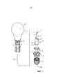
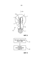
Фиг. 1 показывает схематичное покомпонентное изображение примера осветительного устройства; иFIG. 1 shows a schematic exploded view of an example of a lighting device; and
Фиг. 2-8 показывают схематичные разрезы дополнительных примеров осветительных устройств; иFIG. 2-8 show schematic sections of further examples of lighting devices; and
Фиг. 9 показывает блок-схему последовательности операций некоторых этапов способа изготовления осветительного устройства.FIG. 9 shows a flowchart of some steps of a method for manufacturing a lighting device.
ПОДРОБНОЕ ОПИСАНИЕDETAILED DESCRIPTION
Настоящее изобретение будет теперь описано более полно ниже со ссылкой на сопутствующие чертежи, в которых показаны предпочтительные в данный момент варианты осуществления настоящего изобретения. Настоящее изобретение может быть, однако, реализовано во многих других формах и не должно толковаться как ограниченное вариантами осуществления, изложенными здесь; напротив, эти варианты осуществления обеспечены для полноты и законченности, и полностью передают объем настоящего изобретения специалистам в данной области техники.The present invention will now be described more fully below with reference to the accompanying drawings, in which currently preferred embodiments of the present invention are shown. The present invention may, however, be implemented in many other forms and should not be construed as limited to the embodiments set forth herein; on the contrary, these embodiments are provided for completeness and completeness, and fully convey the scope of the present invention to those skilled in the art.
Фиг. 1 показывает пример осветительного устройства 1 в форме лампы, такой как модернизированная лампа А60. Осветительное устройство 1 имеет оптическую ось ОА, которая является центральной остью осветительного устройства 1. Свет, генерируемый осветительным устройством 1, является в этом примере по существу осесимметричным относительно оптической оси ОА. Соединитель 2 расположен на конце осветительного устройства 1. Соединитель 2 выполнен с возможностью механического и электрического соединения осветительного устройства 1 с ламповым патроном. В показанном варианте осуществления, соединитель 2 является винтовым цоколем, например, винтовым цоколем Е27, но соединитель 2 может быть соединителем другого типа, например, байонетным держателем лампы. Соединитель 2 обычно изготавливают из металла.FIG. 1 shows an example of a lamp-shaped lighting device 1, such as a retrofitted lamp A60. The lighting device 1 has an optical axis OA, which is the central axis of the lighting device 1. The light generated by the lighting device 1 is, in this example, substantially axisymmetric with respect to the optical axis OA. The
Осветительное устройство 1 имеет светопропускающую оболочку 3, центр которой смещен вдоль оптической оси ОА относительно соединителя 2. Оболочка 3 может быть изготовлена, например, из стекла или пластика. В показанном примере, оболочка 3 имеет грушевидную форму, образованную сферической головной частью и круговой цилиндрической суженной частью, причем головная часть и суженная часть являются, соответственно, дистальной частью и ближайшей частью по отношению к соединителю 2. Оболочка 3 наполнена газом, например, гелием или смесью гелия и кислорода. Осветительное устройство 1 является, таким образом, газонаполненной лампой. Может существовать поверхностный слой 3' на внутренней стороне оболочки 3. Поверхностный слой 3' может быть светорассеивающим слоем или преобразующим длину волны слоем. Примеры светорассеивающих слоев включают в себя покрытия из рассеивающих частиц TiO2, BaSO4, или Al2O3 в кремнийорганической полимерной матрице. Примеры преобразующих длину волны слоев включают в себя покрытия, содержащие один или более люминофоров, таких как YAG, LuAG и ECAS.The lighting device 1 has a light-transmitting
Трубчатый носитель 4 источников света (в дальнейшем называемый «носителем» для краткости) центрирован относительно оптической оси ОА внутри оболочки 3. Носитель 4 в этом примере имеет восьмиугольное поперечное сечение, перпендикулярное оптической оси ОА, но возможны другие поперечные сечения, формы, такие как шестиугольное или круглое поперечное сечение. Следует отметить, что другие варианты осуществления осветительного устройства 1 могут иметь носители, которые не являются трубчатыми. Несколько твердотельных источников 5 света (в дальнейшем называемые «источниками света» для краткости) установлены на носителе 4. Источники 5 света и носитель 4 вместе образуют конструкцию L2. Носитель 4 содержит монтажную плату для электрического соединения источников 5 света, например, печатную плату. Носитель 4 также выполнен с возможностью быть радиатором для источников 5 света, обеспечивающим эффективную теплопередачу от источников 5 света в окружающий газ внутри оболочки 3. Источники 5 света могут быть, например, полупроводниковыми светодиодами, органическими светодиодами, полимерными светодиодами или лазерными диодами. Все источники 5 света могут быть выполнены с возможностью излучения света одного и того же цвета, например, белого цвета, или разные источники 5 света могут быть выполнены с возможностью излучения света разных цветов.The
Крепежная деталь 6, иногда называемая «паукообразной деталью», внутри носителя 4, прикрепляет носитель 4 к откачной трубке 7 осветительного устройства 1. Крепежная деталь 6 может, например, иметь выступы, которые сопрягаются с отверстиями в носителе 4, и блокирующий элемент, который скрепляется с откачной трубкой 7. Посредством этого расположения, носитель 4 окружает часть откачной трубки 7 таким образом, что откачная трубка 7 частично расположена во внутреннем пространстве носителя 4. Откачная трубка 7 продолжается вдоль оптической оси ОА, которая совпадает с центральной осью носителя 4. Откачная трубка 7 объединена со стержневым элементом 8, имеющим больший диаметр, чем откачная трубка 7. Стержневой элемент 8 и откачную трубку 7 обычно изготавливают из стекла. Часть откачной трубки 7 находится внутри стержневого элемента 8, а другая часть откачной трубки 7 находится снаружи стержневого элемента 8, причем наружная часть 7' имеет открытый конец 7'' и поддерживает носитель 4 через крепежную деталь 6. Стержневой элемент 8 имеет ближайшую часть 8', которая является ближайшей к соединителю 2, и дистальную часть 8'', которая является дистальной по отношению к соединителю 2. Ближайшая часть 8' спаяна с соединителем 2. Наружная часть 7' откачной трубки 7 продолжается от дистальной части 8'' вдоль оптической оси ОА.The
Контактные провода 9 прикреплены к стержневому элементу 8. Следует отметить, что модуль, состоящий из стержневого элемента 8, откачной трубки 7 и контактных проводов 9, иногда называется «стержнем» лампы. Контактные провода 9 выдаются из стержневого элемента 8 и электрически соединяют носитель 4 с возбудителем 10 для питания энергией источников 5 света. Возбудитель 10 в этом примере расположен внутри соединителя 2, но может быть в других примерах расположен полностью внутри оболочки 3, поддерживаемый, например, носителем 4 или крепежной деталью 6. Изолирующая часть 11, которая электрически изолирует некоторые части возбудителя 10 от соединителя 2, может быть расположена между возбудителем 10 и соединителем 2.The contact wires 9 are attached to the
Антенна 12 беспроводной связи (в дальнейшем называемая «антенной» для краткости) расположена внутри откачной трубки 7, чтобы она была гальванически изолированной от носителя 4. Антенна 12 в этом примере является прямой несимметричной вибраторной антенной. Длина антенны 12 обычно приблизительно равна λ/4, где λ является длиной волны сигнала, который антенна 12 может принимать. Типичная длина антенны равна около 3 см. Схема 13 управления электрически соединена с антенной 12 и монтажной платой, на которой установлены источники 5 света. Схема 13 управления выполнена с возможностью управления источниками 5 света и обычно содержит микроконтроллер и приемник радиоизлучения. Схема 13 управления в этом примере объединена с возбудителем 10, но может быть отдельным блоком в других примерах. Схема 13 управления может питаться энергией от возбудителя 10.The wireless antenna 12 (hereinafter referred to as the "antenna" for short) is located inside the pumping
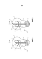
Фиг. 2 показывает пример осветительного устройства 1а, которое подобно осветительному устройству на фиг. 1. Антенна 12а продолжается вплоть до открытого конца 7', не выступая из откачной трубки 7а. Открытый конец 7' расположен внутри носителя 4.FIG. 2 shows an example of a
Фиг. 3 показывает осветительное устройство 1b, которое подобно осветительному устройству на фиг. 1а, за исключением того, что откачная трубка 7b продолжается на всем протяжении внутреннего пространства носителя 4 таким образом, что открытый конец 7' расположен снаружи носителя 4 (более точно, выше него).FIG. 3 shows a
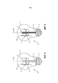
Фиг. 4 показывает осветительное устройство 1с, которое подобно осветительному устройству на фиг. 1, за исключением того, что часть антенны 12с выдается из открытого конца 7' откачной трубки 7с. В показанном примере, открытый конец 7' находится внутри носителя 4, и внешняя часть антенны 12с продолжается прямо вплоть до положения, находящегося снаружи носителя 4. Конечно, внешняя часть антенны 12с может быть в другом примере быть более короткой, таким образом, чтобы она все же находилась полностью внутри носителя 4.FIG. 4 shows a
Фиг. 5 показывает осветительное устройство 1d, которое подобно осветительному устройству на фиг. 4, за исключением того, что внешняя часть антенны 12d загнута вниз таким образом, что она продолжается прямо вдоль внешней поверхности откачной трубки 7d.FIG. 5 shows a
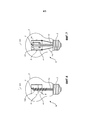
Фиг. 6 показывает осветительное устройство 1е, которое подобно осветительному устройству на фиг. 5, за исключением того, что внешняя часть антенны 12е намотана вокруг откачной трубки 7 таким образом, что она образует катушку.FIG. 6 shows a
Фиг. 7 показывает осветительное устройство 1f, имеющее опорную конструкцию 14, которая прикреплена к откачной трубке 7f и которая поддерживает внешнюю часть антенны 12f на некотором расстоянии от откачной трубки 7f. Внешняя часть антенны 12f имеет в этом примере петлеобразную форму. Кроме того, носитель 4 прикреплен к откачной трубке 7f через опору 15 носителя, которая продолжается вверх от соединителя 2 и которая удерживает носитель 4 на его месте внутри оболочки 3.FIG. 7 shows a
Фиг. 8 показывает осветительное устройство 1g, в котором схема 13 управления расположена полностью внутри оболочки 3. Схема 13 управления прикреплена к носителю 4 источников света и поддерживается им. Внешняя часть антенны 12g электрически соединена со схемой 13 управления.FIG. 8 shows a lighting device 1g in which the
Фиг. 9 показывает блок-схему последовательности операций некоторых этапов способа изготовления осветительного устройства, такого как газонаполненная лампа. Способ включает в себя этап S1, на котором антенну 12 располагают внутри стеклянной откачной трубки 7. Откачную трубку 7, с антенной 12 внутри, помещают в держатель, пригодный для процесса плавления и сплавления стекла, вместе со стеклянным стержневым элементом 8 и контактными проводами 9. Дистальную часть 8'' стержневого элемента 8 нагревают до температуры, при которой стекло становится вязким, и откачную трубку 7 непрямо нагревают до той же самой температуры. Горячее стекло сжимают таким образом, чтобы образовалось воздухонепроницаемое соединение между стержневым элементом 8 и откачной трубкой 7, а также между стержневым элементом 8 и контактными проводами 9. Сжатие стекла создает то, что обычно называется «защемлением» на стержневом элементе 8. Стеклу затем дают до некоторой степени остыть, после чего малую область защемления между контактными проводами 9 нагревают снова и проделывают малое отверстие через защемление посредством введения сжатого воздуха в откачную трубку 7. Это отверстие позволяет соединить откачную трубку 7 с внутренней частью лампы после спаивания стержня 8 с оболочкой 3. Носитель 4 источников света с твердотельными источниками 5 света затем устанавливают на откачную трубку 7 и электрически соединяют с контактными проводами 9, например, сваркой. Весь модуль располагают внутри стеклянной оболочки 3, которую спаивают с ближайшей частью 8' стержневого элемента 8 посредством нагревания стекла снаружи, в то время как модуль стержня и оболочки поворачивают. Затем, лампу продувают, наполняют и закрывают в процессе, который иногда называется «нагнетанием и отпайкой». Внутреннюю часть оболочки 3 очищают многократной продувкой инертным газом, причем используют клапан специального типа для управления потоком газа через откачную трубку 7. Наполняющий газ нагнетают в очищенную оболочку 3 через откачную трубку 3 посредством системы наполнения. Затем, на этапе S2, образуют воздухонепроницаемое соединение между антенной 12 и откачной трубкой 7 таким образом, чтобы наполняющий газ не мог выйти из оболочки 3 через откачную трубку 7. Это может быть реализовано посредством нагревания откачной трубки 7, между оболочкой 3 и клапаном, и сжатия нагретой откачной трубки 7 напротив антенны 12. Часть откачной трубки 7, которая находится снаружи оболочки 3, затем удаляют, например, посредством «образования на поверхности рисок и обламывания» откачной трубки 7. Это включает в себя создание слабого места, которое позволяет обломить откачную трубку 7 в определенном месте. Слабое место может быть создано, например, посредством нанесения царапин на откачную трубку 7 алмазным ножом или посредством локального уменьшения диаметра откачной трубки 7 посредством нагревания и сжимания. Часть антенны 12 обычно выступает из кончика, где была обломлена откачная трубка 7. Если антенна 12 устанавливается верхней стороной вниз, то, однако, можно обломить откачную трубку 7 в некоторой точке таким образом, чтобы впоследствии антенна 12 не выступала из откачной трубки 7. Наконец, соединитель 2 прикрепляют к оболочке 3, и электронные схемы внутри соединителя 2 соединяют с контактными проводами 9 и антенной 12, например, электрической сваркой или пайкой или посредством прокалывающих соединителей или протыкающих соединителей.FIG. 9 shows a flowchart of some steps of a method for manufacturing a lighting device, such as a gas-filled lamp. The method includes a step S1, in which the
Осветительное устройство приводится в действие посредством вставления соединителя 2 в электрическое гнездо, соединенное с источником электроэнергии, в результате чего возбудитель 10 подает энергию на источники 5 света через контактные провода 9 и носитель 4. Источники 5 света излучают свет, который проходит через оболочку 3. Мобильное устройство, такое как смартфон, может быть использовано для управления источниками 5 света посредством отправки радиочастотных сигналов к антенне 12. Сигналы, принимаемые антенной 12, обрабатываются схемой 13 управления, которая управляет источниками 5 света. В зависимости от применения, можно, например, включать и выключать источники света, регулировать яркость источников света и изменять установочные параметры цвета осветительного устройства.The lighting device is driven by inserting a
Специалист в данной области техники понимает, что настоящее изобретение никоим образом не ограничено предпочтительными вариантами осуществления, описанными выше. Напротив, многие модификации и изменения возможны в пределах объема прилагаемой формулы изобретения. Например, форма оболочки 3 не ограничена грушевидной формой. Некоторые примеры других форм оболочки включают в себя цилиндрическую, эллипсоидальную и коническую формы.One of ordinary skill in the art understands that the present invention is in no way limited to the preferred embodiments described above. On the contrary, many modifications and changes are possible within the scope of the attached claims. For example, the shape of the
Дополнительно, изменения раскрытых вариантов осуществления могут быть поняты и реализованы специалистом в данной области техники при применении на практике заявленного изобретения, после изучения чертежей, раскрытия, и прилагаемой формулы изобретения. В формуле изобретения, слово «содержащий» не исключает других элементов или этапов, а форма единственного числа не исключает множественного числа. Тот факт, что некоторые меры приведены во взаимно отличающихся зависимых пунктах формулы изобретения, не указывает на то, что комбинация этих мер не может быть использована для получения преимущества.Additionally, changes to the disclosed embodiments can be understood and implemented by a person skilled in the art when practicing the claimed invention, after studying the drawings, disclosure, and the attached claims. In the claims, the word “comprising” does not exclude other elements or steps, and the singular form does not exclude the plural. The fact that some measures are given in mutually different dependent dependent claims does not indicate that a combination of these measures cannot be used to take advantage.
Claims (24)
Applications Claiming Priority (3)
| Application Number | Priority Date | Filing Date | Title |
|---|---|---|---|
| EP15183300.1 | 2015-09-01 | ||
| EP15183300 | 2015-09-01 | ||
| PCT/EP2016/068748 WO2017036733A1 (en) | 2015-09-01 | 2016-08-05 | Lighting device with a wireless communication antenna |
Publications (3)
| Publication Number | Publication Date |
|---|---|
| RU2018111248A RU2018111248A (en) | 2019-10-02 |
| RU2018111248A3 RU2018111248A3 (en) | 2019-10-15 |
| RU2709099C2 true RU2709099C2 (en) | 2019-12-16 |
Family
ID=54105616
Family Applications (1)
| Application Number | Title | Priority Date | Filing Date |
|---|---|---|---|
| RU2018111248A RU2709099C2 (en) | 2015-09-01 | 2016-08-05 | Lighting device with wireless communication antenna |
Country Status (10)
| Country | Link |
|---|---|
| US (2) | US11175000B2 (en) |
| EP (2) | EP3139086B1 (en) |
| JP (3) | JP7446058B2 (en) |
| CN (1) | CN108027111A (en) |
| DK (1) | DK3351851T3 (en) |
| ES (1) | ES2763277T3 (en) |
| PL (1) | PL3351851T3 (en) |
| PT (1) | PT3351851T (en) |
| RU (1) | RU2709099C2 (en) |
| WO (1) | WO2017036733A1 (en) |
Families Citing this family (6)
| Publication number | Priority date | Publication date | Assignee | Title |
|---|---|---|---|---|
| CA3006288A1 (en) * | 2015-11-24 | 2017-06-01 | Glaxosmithkline Intellectual Property Development Limited | Stable cell lines for retroviral production |
| US10355340B2 (en) * | 2016-06-07 | 2019-07-16 | Signify Holding B.V. | Solid-state lighting device having a wireless communication antenna |
| ES2807580T3 (en) * | 2016-09-19 | 2021-02-23 | Signify Holding Bv | Lighting device comprising a communication element for wireless communication |
| GB2593162B (en) | 2017-09-15 | 2023-04-12 | Technical Consumer Products Inc | Light emitting diode (LED) filament light bulb with secured antenna |
| CN210035113U (en) * | 2019-02-11 | 2020-02-07 | 朗德万斯公司 | Connection module, driver and lamp |
| WO2024175408A1 (en) | 2023-02-23 | 2024-08-29 | Signify Holding B.V. | Lamp with an antenna |
Citations (4)
| Publication number | Priority date | Publication date | Assignee | Title |
|---|---|---|---|---|
| US5504395A (en) * | 1993-03-08 | 1996-04-02 | Beacon Light Products, Inc. | Lamp bulb having integrated RFI suppression and method of restricting RFI to selected level |
| RU2294034C1 (en) * | 2005-10-26 | 2007-02-20 | Закрытое акционерное общество Научно-производственный центр "СОЛИТОН-НТТ" (ЗАО НПЦ "СОЛИТОН-НТТ") | Gas-discharge source of ultra-violet radiation |
| RU113873U1 (en) * | 2011-07-04 | 2012-02-27 | Эдуард Михайлович Бархударов | MICROWAVE DISCHARGE SOURCE OF UV RADIATION |
| WO2013014821A1 (en) * | 2011-07-22 | 2013-01-31 | パナソニック株式会社 | Light source for lighting, and lighting device |
Family Cites Families (29)
| Publication number | Priority date | Publication date | Assignee | Title |
|---|---|---|---|---|
| JPS6040955A (en) | 1983-08-17 | 1985-03-04 | Japan Spectroscopic Co | Automatic micro-plate spectroscopic analysis apparatus and its method |
| JPS6040955U (en) * | 1983-08-30 | 1985-03-22 | 株式会社東芝 | metal vapor discharge lamp |
| FR2715994B1 (en) * | 1994-01-27 | 1996-04-26 | Pleine Lune Internationale | Aerostatic lighting device. |
| CN1161819C (en) * | 1998-05-06 | 2004-08-11 | 泛海企业有限公司 | Cold cathode fluorescent lamp and display |
| US6995513B2 (en) * | 2001-05-08 | 2006-02-07 | Koninklijke Philips Electronics N.V. | Coil antenna/protection for ceramic metal halide lamps |
| JP4763987B2 (en) | 2004-08-27 | 2011-08-31 | 帝人化成株式会社 | Polycarbonate resin composition |
| US7387403B2 (en) * | 2004-12-10 | 2008-06-17 | Paul R. Mighetto | Modular lighting apparatus |
| EP1770820B1 (en) * | 2005-09-28 | 2009-03-11 | Siemens Milltronics Process Instruments Inc. | Galvanic isolation mechanism for a planar circuit |
| US8434883B2 (en) * | 2009-05-11 | 2013-05-07 | SemiOptoelectronics Co., Ltd. | LLB bulb having light extracting rough surface pattern (LERSP) and method of fabrication |
| US8952613B2 (en) * | 2009-05-12 | 2015-02-10 | Leroy E. Anderson | LED room light |
| JP5828065B2 (en) * | 2010-04-19 | 2015-12-02 | パナソニックIpマネジメント株式会社 | Light source device and lighting device |
| US8596821B2 (en) * | 2010-06-08 | 2013-12-03 | Cree, Inc. | LED light bulbs |
| TW201207315A (en) * | 2010-08-05 | 2012-02-16 | Liquidleds Lighting Corp | Method for manufacturing LED light |
| SG188483A1 (en) * | 2010-09-08 | 2013-04-30 | Zhejiang Ledison Optoelectronics Co Ltd | Led light bulb and led light-emitting strip being capable of emitting 4pi light |
| JP5065545B1 (en) * | 2011-08-29 | 2012-11-07 | パナソニック株式会社 | Lamps and luminaires |
| TWI446830B (en) * | 2011-11-30 | 2014-07-21 | Amtran Technology Co Ltd | Light emitting diode light source |
| WO2013105169A1 (en) | 2012-01-10 | 2013-07-18 | ソニー株式会社 | Bulb-type light source device |
| CN103307464B (en) * | 2012-03-12 | 2015-09-23 | 浙江锐迪生光电有限公司 | A kind of LED bulb |
| US8633646B2 (en) | 2012-04-30 | 2014-01-21 | Freescale Semiconductor, Inc. | Method and apparatus for radio-frequency controllable LED lamp fixture antenna |
| CN202834823U (en) * | 2012-06-21 | 2013-03-27 | 浙江锐迪生光电有限公司 | Light-emitting diode (LED) lamp with bulb shell being inflated with air and being directly sealed with glass pipe containing LED and exhaust pipe in melting mode |
| JP6250660B2 (en) * | 2012-06-28 | 2017-12-20 | インテマティックス・コーポレーションIntematix Corporation | Lamp and optical component manufacturing method |
| KR102015911B1 (en) * | 2012-11-12 | 2019-08-29 | 엘지전자 주식회사 | Lighting apparatus |
| CN203442567U (en) * | 2013-09-19 | 2014-02-19 | 上虞远东照明有限公司 | LED (light-emitting diode) lamp bulb |
| CN103499037B (en) | 2013-10-15 | 2016-06-29 | 江苏华英光宝科技股份有限公司 | Power source hidden LED bulb |
| CN103542308A (en) | 2013-11-08 | 2014-01-29 | 江苏华英光宝科技股份有限公司 | All-angle bendable LED (Light Emitting Diode) filament strip and antique LED bulb comprising same |
| CN204153513U (en) * | 2014-10-08 | 2015-02-11 | 新和(绍兴)绿色照明有限公司 | A kind of LED bulb |
| CN104613346A (en) * | 2015-01-16 | 2015-05-13 | 新照明设计有限公司 | Manufacturing method for bulb with three-dimensional LED package |
| CN204328550U (en) * | 2014-12-16 | 2015-05-13 | 深圳市众明半导体照明有限公司 | LED bulb |
| CN204420631U (en) * | 2014-12-31 | 2015-06-24 | 成都世纪光合作用科技有限公司 | A kind of LED illumination device with radio communication function |
-
2016
- 2016-08-05 RU RU2018111248A patent/RU2709099C2/en active
- 2016-08-05 CN CN201680050530.4A patent/CN108027111A/en active Pending
- 2016-08-05 PL PL18154729T patent/PL3351851T3/en unknown
- 2016-08-05 EP EP16182950.2A patent/EP3139086B1/en active Active
- 2016-08-05 DK DK18154729.0T patent/DK3351851T3/en active
- 2016-08-05 EP EP18154729.0A patent/EP3351851B1/en active Active
- 2016-08-05 WO PCT/EP2016/068748 patent/WO2017036733A1/en active Application Filing
- 2016-08-05 JP JP2018510972A patent/JP7446058B2/en active Active
- 2016-08-05 PT PT181547290T patent/PT3351851T/en unknown
- 2016-08-05 ES ES18154729T patent/ES2763277T3/en active Active
- 2016-08-24 US US15/246,159 patent/US11175000B2/en active Active
-
2021
- 2021-08-04 JP JP2021128049A patent/JP2021185569A/en active Pending
- 2021-10-14 US US17/501,458 patent/US11746965B2/en active Active
-
2023
- 2023-03-24 JP JP2023048133A patent/JP2023083301A/en active Pending
Patent Citations (4)
| Publication number | Priority date | Publication date | Assignee | Title |
|---|---|---|---|---|
| US5504395A (en) * | 1993-03-08 | 1996-04-02 | Beacon Light Products, Inc. | Lamp bulb having integrated RFI suppression and method of restricting RFI to selected level |
| RU2294034C1 (en) * | 2005-10-26 | 2007-02-20 | Закрытое акционерное общество Научно-производственный центр "СОЛИТОН-НТТ" (ЗАО НПЦ "СОЛИТОН-НТТ") | Gas-discharge source of ultra-violet radiation |
| RU113873U1 (en) * | 2011-07-04 | 2012-02-27 | Эдуард Михайлович Бархударов | MICROWAVE DISCHARGE SOURCE OF UV RADIATION |
| WO2013014821A1 (en) * | 2011-07-22 | 2013-01-31 | パナソニック株式会社 | Light source for lighting, and lighting device |
Also Published As
| Publication number | Publication date |
|---|---|
| US11746965B2 (en) | 2023-09-05 |
| RU2018111248A (en) | 2019-10-02 |
| WO2017036733A1 (en) | 2017-03-09 |
| ES2763277T3 (en) | 2020-05-27 |
| JP7446058B2 (en) | 2024-03-08 |
| US20170059095A1 (en) | 2017-03-02 |
| US20220065408A1 (en) | 2022-03-03 |
| DK3351851T3 (en) | 2020-01-06 |
| US11175000B2 (en) | 2021-11-16 |
| CN108027111A (en) | 2018-05-11 |
| PL3351851T3 (en) | 2020-05-18 |
| JP2023083301A (en) | 2023-06-15 |
| JP2018526787A (en) | 2018-09-13 |
| EP3139086B1 (en) | 2018-05-23 |
| EP3351851B1 (en) | 2019-10-09 |
| PT3351851T (en) | 2020-01-16 |
| RU2018111248A3 (en) | 2019-10-15 |
| EP3139086A1 (en) | 2017-03-08 |
| JP2021185569A (en) | 2021-12-09 |
| EP3351851A1 (en) | 2018-07-25 |
Similar Documents
| Publication | Publication Date | Title |
|---|---|---|
| RU2709099C2 (en) | Lighting device with wireless communication antenna | |
| US10487990B2 (en) | Lighting device having a wireless communication antenna | |
| JP6235698B2 (en) | Lighting device and antenna including antenna | |
| EP2492978B1 (en) | Light-emitting device, light-emitting module, and lamp | |
| JP5276675B2 (en) | LED thermal management integrated in a bulb-type fluorescent lamp | |
| US9445483B2 (en) | Lighting device and luminaire comprising an integrated antenna | |
| JP2009532823A (en) | Plasma lamp with electric field concentration antenna | |
| JP2012227021A (en) | Illumination light source | |
| US8256938B2 (en) | Method and system for converting a sodium street lamp to an efficient white light source | |
| US8525430B2 (en) | Helical structure and method for plasma lamp | |
| US8384300B2 (en) | Integrated RF electrodeless plasma lamp device and methods | |
| JP4625866B2 (en) | Light bulb type fluorescent lamp | |
| CN202269078U (en) | Radio frequency (RF) electrodeless plasma lighting device | |
| US20110085147A1 (en) | Light source device and projection display device | |
| KR102054759B1 (en) | SSPA Driven Plasma Lamp System | |
| CN202103018U (en) | Plasma lamp device and device for plasma lamp | |
| JP5551562B2 (en) | lamp | |
| JP2011090851A (en) | Electrodeless plasma lamp, and method of generating light with use of electrodeless plasma lamp | |
| US20110204782A1 (en) | Plasma Lamp with Dielectric Waveguide Body Having a Width Greater Than a Length | |
| US20100314999A1 (en) | Lamp device |