JP2023083301A - Lighting device with wireless communication antenna - Google Patents
Lighting device with wireless communication antenna Download PDFInfo
- Publication number
- JP2023083301A JP2023083301A JP2023048133A JP2023048133A JP2023083301A JP 2023083301 A JP2023083301 A JP 2023083301A JP 2023048133 A JP2023048133 A JP 2023048133A JP 2023048133 A JP2023048133 A JP 2023048133A JP 2023083301 A JP2023083301 A JP 2023083301A
- Authority
- JP
- Japan
- Prior art keywords
- lighting device
- antenna
- exhaust pipe
- light source
- source carrier
- Prior art date
- Legal status (The legal status is an assumption and is not a legal conclusion. Google has not performed a legal analysis and makes no representation as to the accuracy of the status listed.)
- Pending
Links
- 238000004891 communication Methods 0.000 title claims abstract description 8
- 238000004519 manufacturing process Methods 0.000 claims abstract description 11
- 239000007787 solid Substances 0.000 claims description 15
- 238000000034 method Methods 0.000 claims description 7
- 238000000149 argon plasma sintering Methods 0.000 claims description 4
- 239000011521 glass Substances 0.000 description 11
- 239000007789 gas Substances 0.000 description 10
- 239000010410 layer Substances 0.000 description 9
- 230000003287 optical effect Effects 0.000 description 8
- 238000005286 illumination Methods 0.000 description 5
- 238000005516 engineering process Methods 0.000 description 3
- 238000010438 heat treatment Methods 0.000 description 3
- 235000014443 Pyrus communis Nutrition 0.000 description 2
- GWEVSGVZZGPLCZ-UHFFFAOYSA-N Titan oxide Chemical compound O=[Ti]=O GWEVSGVZZGPLCZ-UHFFFAOYSA-N 0.000 description 2
- TZCXTZWJZNENPQ-UHFFFAOYSA-L barium sulfate Chemical compound [Ba+2].[O-]S([O-])(=O)=O TZCXTZWJZNENPQ-UHFFFAOYSA-L 0.000 description 2
- 230000015556 catabolic process Effects 0.000 description 2
- 230000008859 change Effects 0.000 description 2
- 238000000576 coating method Methods 0.000 description 2
- 238000006731 degradation reaction Methods 0.000 description 2
- 230000000694 effects Effects 0.000 description 2
- 239000001307 helium Substances 0.000 description 2
- 229910052734 helium Inorganic materials 0.000 description 2
- SWQJXJOGLNCZEY-UHFFFAOYSA-N helium atom Chemical compound [He] SWQJXJOGLNCZEY-UHFFFAOYSA-N 0.000 description 2
- 239000011261 inert gas Substances 0.000 description 2
- 239000000203 mixture Substances 0.000 description 2
- 230000005404 monopole Effects 0.000 description 2
- 238000003825 pressing Methods 0.000 description 2
- 230000008569 process Effects 0.000 description 2
- 239000004065 semiconductor Substances 0.000 description 2
- 239000002344 surface layer Substances 0.000 description 2
- 238000003466 welding Methods 0.000 description 2
- 241000239290 Araneae Species 0.000 description 1
- PNEYBMLMFCGWSK-UHFFFAOYSA-N aluminium oxide Inorganic materials [O-2].[O-2].[O-2].[Al+3].[Al+3] PNEYBMLMFCGWSK-UHFFFAOYSA-N 0.000 description 1
- QVGXLLKOCUKJST-UHFFFAOYSA-N atomic oxygen Chemical compound [O] QVGXLLKOCUKJST-UHFFFAOYSA-N 0.000 description 1
- 230000008901 benefit Effects 0.000 description 1
- 239000000969 carrier Substances 0.000 description 1
- 239000003086 colorant Substances 0.000 description 1
- 239000004020 conductor Substances 0.000 description 1
- 229910052593 corundum Inorganic materials 0.000 description 1
- 230000008878 coupling Effects 0.000 description 1
- 238000010168 coupling process Methods 0.000 description 1
- 238000005859 coupling reaction Methods 0.000 description 1
- 230000001419 dependent effect Effects 0.000 description 1
- 229910003460 diamond Inorganic materials 0.000 description 1
- 239000010432 diamond Substances 0.000 description 1
- 238000006073 displacement reaction Methods 0.000 description 1
- 238000009826 distribution Methods 0.000 description 1
- 230000002708 enhancing effect Effects 0.000 description 1
- 238000011010 flushing procedure Methods 0.000 description 1
- 230000007774 longterm Effects 0.000 description 1
- 239000011159 matrix material Substances 0.000 description 1
- 230000007246 mechanism Effects 0.000 description 1
- 238000002844 melting Methods 0.000 description 1
- 230000008018 melting Effects 0.000 description 1
- 238000010309 melting process Methods 0.000 description 1
- 239000002184 metal Substances 0.000 description 1
- 238000012986 modification Methods 0.000 description 1
- 230000004048 modification Effects 0.000 description 1
- 239000001301 oxygen Substances 0.000 description 1
- 229910052760 oxygen Inorganic materials 0.000 description 1
- 230000003071 parasitic effect Effects 0.000 description 1
- 239000002245 particle Substances 0.000 description 1
- 229920000642 polymer Polymers 0.000 description 1
- 238000005086 pumping Methods 0.000 description 1
- 238000006748 scratching Methods 0.000 description 1
- 230000002393 scratching effect Effects 0.000 description 1
- 230000035945 sensitivity Effects 0.000 description 1
- 229920005573 silicon-containing polymer Polymers 0.000 description 1
- 238000005476 soldering Methods 0.000 description 1
- 229910001845 yogo sapphire Inorganic materials 0.000 description 1
Images


Classifications
-
- F—MECHANICAL ENGINEERING; LIGHTING; HEATING; WEAPONS; BLASTING
- F21—LIGHTING
- F21K—NON-ELECTRIC LIGHT SOURCES USING LUMINESCENCE; LIGHT SOURCES USING ELECTROCHEMILUMINESCENCE; LIGHT SOURCES USING CHARGES OF COMBUSTIBLE MATERIAL; LIGHT SOURCES USING SEMICONDUCTOR DEVICES AS LIGHT-GENERATING ELEMENTS; LIGHT SOURCES NOT OTHERWISE PROVIDED FOR
- F21K99/00—Subject matter not provided for in other groups of this subclass
-
- F—MECHANICAL ENGINEERING; LIGHTING; HEATING; WEAPONS; BLASTING
- F21—LIGHTING
- F21K—NON-ELECTRIC LIGHT SOURCES USING LUMINESCENCE; LIGHT SOURCES USING ELECTROCHEMILUMINESCENCE; LIGHT SOURCES USING CHARGES OF COMBUSTIBLE MATERIAL; LIGHT SOURCES USING SEMICONDUCTOR DEVICES AS LIGHT-GENERATING ELEMENTS; LIGHT SOURCES NOT OTHERWISE PROVIDED FOR
- F21K9/00—Light sources using semiconductor devices as light-generating elements, e.g. using light-emitting diodes [LED] or lasers
- F21K9/90—Methods of manufacture
-
- F—MECHANICAL ENGINEERING; LIGHTING; HEATING; WEAPONS; BLASTING
- F21—LIGHTING
- F21K—NON-ELECTRIC LIGHT SOURCES USING LUMINESCENCE; LIGHT SOURCES USING ELECTROCHEMILUMINESCENCE; LIGHT SOURCES USING CHARGES OF COMBUSTIBLE MATERIAL; LIGHT SOURCES USING SEMICONDUCTOR DEVICES AS LIGHT-GENERATING ELEMENTS; LIGHT SOURCES NOT OTHERWISE PROVIDED FOR
- F21K9/00—Light sources using semiconductor devices as light-generating elements, e.g. using light-emitting diodes [LED] or lasers
- F21K9/20—Light sources comprising attachment means
- F21K9/23—Retrofit light sources for lighting devices with a single fitting for each light source, e.g. for substitution of incandescent lamps with bayonet or threaded fittings
- F21K9/232—Retrofit light sources for lighting devices with a single fitting for each light source, e.g. for substitution of incandescent lamps with bayonet or threaded fittings specially adapted for generating an essentially omnidirectional light distribution, e.g. with a glass bulb
-
- F—MECHANICAL ENGINEERING; LIGHTING; HEATING; WEAPONS; BLASTING
- F21—LIGHTING
- F21V—FUNCTIONAL FEATURES OR DETAILS OF LIGHTING DEVICES OR SYSTEMS THEREOF; STRUCTURAL COMBINATIONS OF LIGHTING DEVICES WITH OTHER ARTICLES, NOT OTHERWISE PROVIDED FOR
- F21V23/00—Arrangement of electric circuit elements in or on lighting devices
- F21V23/04—Arrangement of electric circuit elements in or on lighting devices the elements being switches
- F21V23/0435—Arrangement of electric circuit elements in or on lighting devices the elements being switches activated by remote control means
-
- H—ELECTRICITY
- H05—ELECTRIC TECHNIQUES NOT OTHERWISE PROVIDED FOR
- H05B—ELECTRIC HEATING; ELECTRIC LIGHT SOURCES NOT OTHERWISE PROVIDED FOR; CIRCUIT ARRANGEMENTS FOR ELECTRIC LIGHT SOURCES, IN GENERAL
- H05B47/00—Circuit arrangements for operating light sources in general, i.e. where the type of light source is not relevant
- H05B47/10—Controlling the light source
- H05B47/175—Controlling the light source by remote control
- H05B47/19—Controlling the light source by remote control via wireless transmission
-
- F—MECHANICAL ENGINEERING; LIGHTING; HEATING; WEAPONS; BLASTING
- F21—LIGHTING
- F21V—FUNCTIONAL FEATURES OR DETAILS OF LIGHTING DEVICES OR SYSTEMS THEREOF; STRUCTURAL COMBINATIONS OF LIGHTING DEVICES WITH OTHER ARTICLES, NOT OTHERWISE PROVIDED FOR
- F21V23/00—Arrangement of electric circuit elements in or on lighting devices
- F21V23/04—Arrangement of electric circuit elements in or on lighting devices the elements being switches
- F21V23/0442—Arrangement of electric circuit elements in or on lighting devices the elements being switches activated by means of a sensor, e.g. motion or photodetectors
- F21V23/045—Arrangement of electric circuit elements in or on lighting devices the elements being switches activated by means of a sensor, e.g. motion or photodetectors the sensor receiving a signal from a remote controller
-
- F—MECHANICAL ENGINEERING; LIGHTING; HEATING; WEAPONS; BLASTING
- F21—LIGHTING
- F21Y—INDEXING SCHEME ASSOCIATED WITH SUBCLASSES F21K, F21L, F21S and F21V, RELATING TO THE FORM OR THE KIND OF THE LIGHT SOURCES OR OF THE COLOUR OF THE LIGHT EMITTED
- F21Y2101/00—Point-like light sources
-
- H—ELECTRICITY
- H05—ELECTRIC TECHNIQUES NOT OTHERWISE PROVIDED FOR
- H05B—ELECTRIC HEATING; ELECTRIC LIGHT SOURCES NOT OTHERWISE PROVIDED FOR; CIRCUIT ARRANGEMENTS FOR ELECTRIC LIGHT SOURCES, IN GENERAL
- H05B47/00—Circuit arrangements for operating light sources in general, i.e. where the type of light source is not relevant
- H05B47/10—Controlling the light source
- H05B47/175—Controlling the light source by remote control
- H05B47/196—Controlling the light source by remote control characterised by user interface arrangements
- H05B47/1965—Controlling the light source by remote control characterised by user interface arrangements using handheld communication devices
Landscapes
- Engineering & Computer Science (AREA)
- General Engineering & Computer Science (AREA)
- Physics & Mathematics (AREA)
- Microelectronics & Electronic Packaging (AREA)
- Optics & Photonics (AREA)
- Computer Networks & Wireless Communication (AREA)
- Manufacturing & Machinery (AREA)
- Arrangement Of Elements, Cooling, Sealing, Or The Like Of Lighting Devices (AREA)
- Non-Portable Lighting Devices Or Systems Thereof (AREA)
Abstract
Description
本発明は、典型的には固体照明(SSL)技術に基づいていると共に無線通信アンテナを有する照明装置に関する。本発明はまた、このような照明装置を製造する方法に関する。 The present invention relates to a lighting device typically based on solid state lighting (SSL) technology and having a wireless communication antenna. The invention also relates to a method of manufacturing such a lighting device.
固体光源の無線制御のためのアンテナを有するSSL技術に基づく照明装置は、当技術分野では知られている。放射された光の強度及び色は、例えば、このようにして制御することができる。この種の照明装置は、国際公開第2013014821号パンフレットに開示されている。当該照明装置は、半導体発光素子のための支持部材の内部又は周囲に配され得るアンテナを有する。 Lighting devices based on SSL technology with antennas for wireless control of solid state light sources are known in the art. The intensity and color of the emitted light can, for example, be controlled in this way. A lighting device of this kind is disclosed in WO2013014821. The lighting device has an antenna that can be arranged in or around a support member for the semiconductor light emitting device.
既存の照明装置の設計に著しい変更を伴うことなくアンテナを組み込む方法を見出すことが望ましく、この結果、製造プロセスに不要なコスト及び複雑さが加わることが回避される。ここで要因を複雑にするのは、アンテナの技術的性能が、照明装置の内側におけるこの位置によって影響されるという事実である。 It would be desirable to find a way to incorporate the antenna without significant changes to existing lighting device designs, thus avoiding adding unnecessary cost and complexity to the manufacturing process. Complicating the factor here is the fact that the technical performance of the antenna is influenced by its position inside the lighting device.
本発明の目的は、無線通信アンテナを有する改善された又は代替的な照明装置を提供することにある。 SUMMARY OF THE INVENTION It is an object of the present invention to provide an improved or alternative lighting device with a wireless communication antenna.
第1の見地によれば、排気管と、この排気管の内部に配された無線通信アンテナとを備える照明装置が提供される。 According to a first aspect, there is provided a lighting device comprising an exhaust pipe and a wireless communication antenna arranged inside the exhaust pipe.
「排気管」とは、これを通って気体が製造中に照明装置に導入され、後で封止される管を意味する。排気管は、しばしば一般照明サービス(GLS)電球、即ち従来の白熱電球に見られる。このような電球の製造中、排気管は、空気がバルブから排出され、不活性気体がバルブ内に圧送されることを可能にする。SSL技術に基づく現代の照明装置は、固体光源を囲むエンベロープ内に気体を導入するための排気管を有することもできる。気体は、固体光源のルーメンの低下を低減することによって、固体光源からの熱輸送及び照明装置の寿命を改善することができる。排気管は電気的に絶縁されており、例えばガラス製であっても良い。 By "exhaust tube" is meant a tube through which gas is introduced into the lighting device during manufacture and which is subsequently sealed. Exhaust pipes are often found in General Lighting Service (GLS) bulbs, ie conventional incandescent bulbs. During manufacture of such bulbs, an exhaust tube allows air to be evacuated from the bulb and inert gas to be pumped into the bulb. Modern lighting devices based on SSL technology can also have an exhaust pipe for introducing gas into the envelope surrounding the solid state light source. The gas can improve heat transport from the solid state light source and lifetime of the lighting device by reducing the lumen degradation of the solid state light source. The exhaust pipe is electrically insulated and may be made of glass, for example.
アンテナが「内側」に配されることによって、排気管は、アンテナの少なくとも一部が排気管によって形成される内部空間の内側にあることを意味する。アンテナは、排気管の外側に配される別の部分を有しても良い。 By arranging the antenna "inside", it is meant that the exhaust pipe is at least partly inside the interior space formed by the exhaust pipe. The antenna may have another portion that is arranged outside the exhaust pipe.
アンテナを排気管の内部に配することにより、アンテナは機械的に良好に支持され、エンドユーザによる荒い取り扱いのためにアンテナが変位する危険性が低減される。このことは、アンテナが最適に動作するようにアンテナを適切に配する必要があるために重要である。また、アンテナがこの位置にある場合、アンテナが固体光源から放射される光の光路とアンテナが干渉しないように照明装置を設計することが容易であり、ヒートシンク又はエレクトロニクスユニットは、例えばシールドによるアンテナ性能の低下のリスクが小さいようなアンテナからの距離にある。更に、アンテナを排気管の内側に配することは、生産工程に僅かなコスト及び複雑さを加えるのみである単純な工程である。例えば、このことは、長期間にわたるコストの効率及び速度に関して最適化された既存のGLS生産ラインの多くを使用することが依然として可能である。 By locating the antenna inside the exhaust pipe, the antenna is well supported mechanically and the risk of antenna displacement due to rough handling by the end user is reduced. This is important because the antenna must be properly positioned for optimal operation. Also, when the antenna is in this position, it is easy to design the lighting device so that it does not interfere with the optical path of the light emitted from the solid-state light source, and the heat sink or electronics unit can be used to improve the performance of the antenna, for example by shielding. at a distance from the antenna such that the risk of degradation of Moreover, placing the antenna inside the exhaust pipe is a simple process that adds little cost and complexity to the production process. For example, it is still possible to use many of the existing GLS production lines optimized for cost efficiency and speed over the long term.
一実施例によれば、アンテナの外側部分は、排気管の開放端から突出している。アンテナは、通常、特定の周波数の信号に最適に高感度であるために特定の長さを有する必要がある。最適なアンテナの長さは、場合によっては排気管よりも長くなることがあり、この問題の解決策は、アンテナを排気管から突出させることである。排気管から突出するアンテナの部分は、例えば、照明装置内部の自由空間の量に依存して多くの異なる仕方で配されることができる。 According to one embodiment, the outer portion of the antenna protrudes from the open end of the exhaust pipe. Antennas usually need to have a certain length for optimal sensitivity to signals of a certain frequency. The optimal antenna length can be longer than the exhaust pipe in some cases, and the solution to this problem is to let the antenna protrude from the exhaust pipe. The part of the antenna that protrudes from the exhaust pipe can be arranged in many different ways, for example depending on the amount of free space inside the lighting device.
一実施例によれば、アンテナの外側部分は排気管に沿って真っ直ぐに延在している。 According to one embodiment, the outer part of the antenna extends straight along the exhaust pipe.
一実施例によれば、アンテナの外側部分は、排気管の周りに巻き付けられる。 According to one embodiment, the outer part of the antenna is wrapped around the exhaust pipe.
一実施例によれば、照明装置は、排気管から距離を置いてアンテナの外側部分を支持する支持構造を更に有する。 According to one embodiment, the lighting device further comprises a support structure supporting the outer part of the antenna at a distance from the exhaust pipe.
一実施例によれば、照明装置は、排気管に取り付けられた管状光源キャリアを更に備え、排気管は、部分的に管状光源キャリアの内側に配される。管状光源キャリアは、キャリアを通る対流を生成することによって光源からの効率的な熱輸送を促進する。別の言い方をすれば、管状光源キャリアは、熱煙突効果を生じ得る。キャリアは、アンテナの受信特性、例えば帯域幅を改善することもできることに留意されたい。より具体的には、アンテナが直線状のモノポールアンテナである場合、キャリアは、アンテナの端部チップとカウンタポールとして作用する接地面との間の容量性結合を増大させ、これにより端部チップにおける電流を増大させるために使用され得る。言い換えれば、キャリアは、アンテナの端部チップと地面との間の寄生容量を増大させるために使用されても良い。 According to one embodiment, the lighting device further comprises a tubular light source carrier attached to the exhaust pipe, the exhaust pipe being partially arranged inside the tubular light source carrier. A tubular light source carrier facilitates efficient heat transport from the light source by creating convection currents through the carrier. Stated another way, a tubular light source carrier can create a thermal chimney effect. Note that a carrier can also improve the reception characteristics of an antenna, eg bandwidth. More specifically, if the antenna is a linear monopole antenna, the carrier increases the capacitive coupling between the antenna's end tip and the ground plane acting as a counterpole, thereby increasing the end tip can be used to increase the current in the In other words, the carrier may be used to increase the parasitic capacitance between the antenna's end tip and ground.
一実施例によれば、排気管の開放端は、管状光源キャリアの内側に位置する。 According to one embodiment, the open end of the exhaust tube is located inside the tubular light source carrier.
一実施例によれば、排気管は、前記排気管の開放端が管状光源キャリアの外側にあるように、管状光源キャリアの全体にわたって延在する。 According to one embodiment, the exhaust tube extends throughout the tubular light source carrier such that the open end of said exhaust tube is outside the tubular light source carrier.
一実施例によれば、管状光源キャリアは放射体として作用するように適合され、管状光源キャリアの電気共振周波数はアンテナの受信周波数にほぼ等しい。受信される信号は、通常、周波数範囲を有し、管状光源キャリアの共振周波数は実際には狭い周波数範囲であることに留意されたい。この狭い周波数範囲は、通常、受信される信号の周波数範囲に対して中心に位置し、受信される信号の周波数範囲よりはるかに小さい。狭い周波数範囲は、例えば、受信される信号の周波数範囲の約4%であっても良い。導電性材料を含むキャリアは、アンテナが受信するように構成された周波数で共振するように作製することができる。これは、共振キャリアが受信される信号を向上させる二次放射器として動作するので、アンテナの弱い信号の受信を改善することができる。共振が起こるためには、キャリアはアンテナの近接場領域に位置決めされなければならず、キャリアの寸法(高さ及び幅等)は、キャリアが受信される信号の周波数に一致する電気的共振周波数を有するようにあるべきである。 According to one embodiment, the tubular light source carrier is adapted to act as a radiator and the electrical resonance frequency of the tubular light source carrier is approximately equal to the receive frequency of the antenna. Note that the received signal typically has a range of frequencies, and the resonant frequency of the tubular light source carrier is actually a narrow frequency range. This narrow frequency range is typically centered relative to the frequency range of the received signal and much smaller than the frequency range of the received signal. The narrow frequency range may be, for example, approximately 4% of the frequency range of the received signal. A carrier comprising a conductive material can be made to resonate at the frequency that the antenna is configured to receive. This can improve weak signal reception of the antenna as the resonant carrier acts as a secondary radiator enhancing the received signal. For resonance to occur, the carrier must be positioned in the near-field region of the antenna, and the dimensions of the carrier (height and width, etc.) are such that the carrier has an electrical resonance frequency that matches the frequency of the signal being received. as it should be.
一実施例によれば、照明装置は、照明装置をランプソケットに機械的かつ電気的に接続するためのコネクタと;1つ以上の固体光源を有する光源キャリアと;前記光源キャリア及び前記排気チューブが内側に配されている光透過性エンベロープと;前記1つ以上の固体光源に電力を供給するドライバと;前記アンテナに電気的に接続されると共に前記1つ又は複数の固体光源を制御するように構成された制御回路と;を有する。光源キャリアは、例えば、上述した管状光源キャリアであっても良い。 According to one embodiment, the lighting device comprises a connector for mechanically and electrically connecting the lighting device to a lamp socket; a light source carrier having one or more solid state light sources; a light transmissive envelope disposed within; a driver for powering said one or more solid state light sources; and electrically connected to said antenna and for controlling said one or more solid state light sources. a configured control circuit; The light source carrier may for example be a tubular light source carrier as described above.
一実施例によれば、制御回路は、例えば光源キャリアによって支持されたエンベロープの内側に完全に位置決めされる。制御回路がエンベロープ内に完全に位置決めされている場合、アンテナが、制御回路がコネクタ内に位置決めされている場合にどのように配されるかに関して、逆さに位置決めされても良い。これは、(アンテナが当該仕方にない場合には排気管が閉じられることができないので)排気管を閉じることを容易にすることができ、制御回路を固体光源に電気的に接続することも容易にし得る。 According to one embodiment, the control circuit is positioned completely inside the envelope, for example supported by the light source carrier. If the control circuit is positioned entirely within the envelope, the antenna may be positioned upside down with respect to how it would be arranged if the control circuit were positioned within the connector. This can make it easier to close the exhaust (because the exhaust cannot be closed if the antenna is not in that way) and it is also easier to electrically connect the control circuitry to the solid state light source. can be
一実施例によれば、照明装置は、光散乱層及び/又は波長変換層を更に有する。このような層は、例えば、光透過性エンベロープ上又は固体光源上に配されることができる。散乱層は、光の強度又は色をより均一にすることによって、光分布を改善することができる。波長変換層は、固体光源によって放射される光の色を変えるために使用されても良い。例えば、白色光を提供するための一般的な技術は、非白色光源を波長変換器と組み合わせることである。波長変換器は、光源によって放射された光の一部を、変換された光と変換されていない光との混合が目に白色又はほぼ白色に見えるような波長に変換する。 According to one embodiment, the lighting device further comprises a light scattering layer and/or a wavelength converting layer. Such layers can be disposed, for example, on a light transmissive envelope or on a solid state light source. A scattering layer can improve light distribution by making the light intensity or color more uniform. A wavelength converting layer may be used to change the color of light emitted by a solid state light source. For example, a common technique for providing white light is to combine a non-white light source with a wavelength converter. A wavelength converter converts a portion of the light emitted by the light source to a wavelength such that the mixture of converted and unconverted light appears white or nearly white to the eye.
一実施例によれば、照明装置は、気体充填された電球である。 According to one embodiment, the lighting device is a gas-filled light bulb.
第2の見地によれば、照明装置の排気管の内側にアンテナを配するステップを有する、照明装置を製造する方法が提供される。第2の見地のフィーチャ及び効果は、第1の見地と同様である。 According to a second aspect, there is provided a method of manufacturing a lighting device comprising placing an antenna inside an exhaust pipe of the lighting device. The features and effects of the second aspect are similar to the first aspect.
一実施例によれば、この方法は、アンテナと排気管との間に気密接続を形成するステップを更に有する。 According to one embodiment, the method further comprises forming an airtight connection between the antenna and the exhaust pipe.
本発明は、特許請求の範囲に記載されたフィーチャの全ての可能な組み合わせに関する。 The invention relates to all possible combinations of the features recited in the claims.
以下、添付の図面を参照して、本発明をより詳細に説明する。 The invention will now be described in more detail with reference to the accompanying drawings.
以下、添付の図面を参照して、本発明の好ましい実施例を詳細に説明する。しかしながら、本発明は、多くの異なる形態で実施することができ、本明細書に記載の実施例に限定されるものと解釈すべきではなく、むしろ、これらの実施例は、完全性及び完全性のために提供され、本発明の範囲を当業者に完全に伝える。 Preferred embodiments of the present invention will now be described in detail with reference to the accompanying drawings. This invention may, however, be embodied in many different forms and should not be construed as limited to the examples set forth herein, but rather these examples for completeness and completeness. , to fully convey the scope of the invention to those skilled in the art.
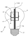
図1は、レトロフィットA60電球のような、電球の形態の照明装置1の例を示す。照明装置1は、照明装置1の中心軸である光軸OAを有する。照明装置1によって生成される照明は、この例では、光軸OAを中心として実質的に回転対称である。照明装置1の端部にはコネクタ2が配されている。コネクタ2は、照明装置1をランプソケットに機械的かつ電気的に接続される。図示された例では、コネクタ2はネジベース、例えばE27ネジベースであるが、コネクタ2は異なるタイプ、例えばバヨネット式の電球マウントであっても良い。コネクタ2は、典型的には金属製である。
Figure 1 shows an example of a lighting device 1 in the form of a bulb, such as a retrofit A60 bulb. The illumination device 1 has an optical axis OA that is the central axis of the illumination device 1 . The illumination produced by the illumination device 1 is in this example substantially rotationally symmetrical about the optical axis OA. A
照明装置1は光透過性エンベロープ3を有し、この中心はコネクタ2に対して光軸OAに沿って変位される。エンベロープ3は、例えば、ガラス又はプラスチックで作ることができる。図示された例では、エンベロープ3は、それぞれコネクタ2の遠位側及び近位側にある丸頭部及び円形円筒状の首部によって形成された梨形状を有する。エンベロープ3は、気体、例えばヘリウム又はヘリウムと酸素の混合物で満たされている。従って、照明装置1は、気体充填された電球である。エンベロープ3の内側には表面層3'が設けられても良い。表面層3'は、光散乱層又は波長変換層であっても良い。光散乱層の例には、シリコーンポリマーマトリックス中のTiO2、BaSO4又はAl2O3散乱粒子のコーティングが含まれる。波長変換層の例は、YAG、LuAG及びECASのような、1つ又は複数の蛍光体を有するコーティングを含む。
The illumination device 1 has a light-
管状の光源キャリア4(以下、簡潔にするために「キャリア」と呼ぶ)は、エンベロープ3内の光軸OAに中心を置かれている。この例におけるキャリア4は、光軸OAに垂直な八角形の断面を有するが、六角形又は円形の断面のような、他の断面形状も可能である。照明装置1の他の実施例は、管状ではないキャリアを有しても良いことに留意されたい。幾つかの固体光源5(以下、簡潔にするために「光源」と呼ぶ)が、キャリア4上に取り付けられている。光源5及びキャリア4は一緒にL2構造を形成している。キャリア4は、光源5を電気的に接続する回路基板、例えばプリント回路基板を有する。また、キャリア4は光源5のヒートシンクであり、光源5からエンベロープ3内の周囲の気体に熱を効率的に輸送することができるようになっている。光源5は、例えば、半導体発光ダイオード、有機発光ダイオード、ポリマー発光ダイオード、又はレーザダイオードであっても良い。光源5の全ては、同じ色の光(例えば白色光)を放射するように構成されてもよく、又は異なる光源5が異なる色の光を放射するように構成されても良い。
A tubular light source carrier 4 (hereinafter referred to as “carrier” for brevity) is centered on the optical axis OA within the
キャリア4内の、「スパイダ」と称されることがある留め具6が、キャリア4を照明装置1の排気管7に取り付ける。留め具6は、例えば、キャリア4内の穴と嵌合する突起部と、排気管7をクランプするロック機構とを有することができる。この構成により、キャリア4は、排気管7がキャリア4の内部空間に部分的に配されるように排気管7の一部を包囲する。排気管7は、キャリア4の中心軸と一致する光軸OAに沿って延在している。排気管7は、排気管7よりも大きな直径を有するステム要素8と一体化されている。ステム要素8及び排気管7は、典型的にはガラス製である。排気管7の一部はステム要素8の内側にあり、排気管7の他の部分はステム要素8の外側にあり、外側部分7'は開口端7''を有すると共に留め具6を介して支持体4を支持している。ステム要素8は、コネクタ2の近位側にある近位部分8'と、コネクタ2の遠位側にある遠位部分8''とを有する。近位部分8'は、コネクタ2に対して封止されている。排気管7の外側部分7'は、遠位部分8''から光軸OAに沿って延在している。
A
コンタクトワイヤ9はステム要素8に固定されている。ステム要素8、排気管7及び接触ワイヤ9からなるアセンブリは、電球の「ステム」と呼ばれることがあることに留意されたい。接触ワイヤ9は、ステム要素8から突出していると共に、キャリア4を光源5に電力を供給するドライバ10を電気的に接続する。この例では、ドライバ10はコネクタ2の内部に配されているが、他の例では、例えばキャリア4又は留め具6によって支持されたエンベロープ3の内部に完全に配されても良い。ドライバ10とコネクタ2との間には、ドライバ10の一部をコネクタ2から電気的に絶縁するための絶縁部11が設けられている。
A contact wire 9 is fixed to the
排気管7の内部には、キャリア4と電気的に絶縁されるように、無線通信用アンテナ12(以下、簡略化のため「アンテナ」と称する)が配されている。この例におけるアンテナ12は、直線状のモノポールアンテナである。アンテナ12の長さは、通常□/4にほぼ等しく、□とはアンテナ12が受信するように構成された信号の波長である。典型的なアンテナの長さは約3cmである。制御回路13は、アンテナ12と、光源5が実装された回路基板とに電気的に接続されている。制御回路13は、光源5を制御するように構成され、通常、マイクロコントローラ及び無線周波数受信機を有する。制御回路13はこの例ではドライバ10と一体化されているが、他の例では別個のユニットであっても良い。制御回路13は、ドライバ10によって電力供給されても良い。
A wireless communication antenna 12 (hereinafter referred to as “antenna” for simplification) is arranged inside the
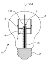
図2は、図1のものと同様の照明装置1aの例を示す。アンテナ12aは、排気管7aから突出することなく、開口端7'まで延在している。開放端7'は、キャリア4の内側に位置する。
FIG. 2 shows an example of a
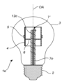
図3は、図1aのものと同様の照明装置1bを示しているが、排気管7bは、開口端7'がキャリア4の外側に(より正確にはキャリア4の上方に)配されるように、キャリア4の内部空間を貫通して延在する。
FIG. 3 shows a
図4は、アンテナ12cの一部が排気管7cの開放端7'から突出していることを除いて図1のものと同様の、照明装置1cを示す。図示した例では、開口端7'はキャリア4の内側にあり、アンテナ12cの外側部分はキャリア4の外側まで真っ直ぐに延在している。勿論、アンテナ12cの外側部分は、別の例では、これが依然としてキャリア4の内部に完全に収まるように、より短くても良い。
FIG. 4 shows a
図5は、アンテナ12dの外側部分が排気管7dの外面に沿って真っ直ぐに延在するように下方に曲げられていることを除いて図4のものと同様の照明装置1dを示す。
FIG. 5 shows a
図6は、アンテナ12eの外側部分がコイルを形成するように排気管7に巻かれていることを除いて図5の照明装置と同様の照明装置1eを示している。
FIG. 6 shows a
図7は、排気管7fに取り付けられると共に、排気管7fから離れたところでアンテナ12fの外側部分を支持する支持構造14を有する照明装置1fを示す。アンテナ12fの外側部分は、この例ではループ状の形状を有する。更に、キャリア4は、コネクタ2から上方に延在すると共にキャリア4をエンベロープ3内の定位置に保持するキャリア支持体15を介して排気管7fに取り付けられている。
Figure 7 shows a lighting device 1f having a support structure 14 attached to the exhaust pipe 7f and supporting the outer portion of the antenna 12f at a distance from the exhaust pipe 7f. The outer portion of antenna 12f has a loop-like shape in this example. Further, the
図8は、制御回路13がエンベロープ3内に完全に位置する照明装置1gを示す。制御回路13は、光源キャリア4に取り付けられて支持されている。アンテナ12gの外側は、制御回路13に電気的に接続されている。
FIG. 8 shows a lighting device 1g in which the
図9は、気体充填電球のような照明装置を製造するための方法の幾つかのステップのフローチャートを示す。この方法は、ガラス製の排気管7の内部にアンテナ12を配するステップS1を含む。アンテナ12が内部にある排気管7は、ガラスステム要素8及び接触ワイヤ9とともにガラス溶融及び溶融プロセスに適したホルダ内に入れられる。ステム要素8の遠位部分8"はガラスが粘性になる温度まで加熱され、排気管7は間接的に同じ温度に加熱される。高温ガラスはプレスされ、ステム要素8と排気管7との間、及びステム要素8と接触ワイヤ9との間に気密接続が形成される。ガラスのプレスにより、ステム要素8上に「ピンチ」と呼ばれるものが形成される。この後、ガラスはいくらか冷却され、この後、接触ワイヤ9の間のピンチの小さな領域が再び加熱され、排気チューブ7内に加圧空気を導入することによってピンチを通して小さな孔が形成される。ひとたびステム8がエンベロープ3に封止されると、孔は電球の内部に排気管7を接続することを可能にする。次に、固体光源5を有する光源キャリア4は排気管7に取り付けられ、例えば溶接によって接触ワイヤ9に電気的に接続される。アセンブリ全体は、ガラスエンベロープ3内に配され、ガラスエンベロープ3は、ステム及びエンベロープアセンブリが回転されている間にガラスを外部から加熱することによって、ステム要素8の近位部分8'に封止される。次に、電球は、「ポンピング及びチッピング」と称されるプロセスにおいて、フラッシュされ、充填され、閉じられる。エンベロープ3の内部は、不活性気体による繰り返しのフラッシングによって清浄化され、排気管7を通る気流を制御するために特別なタイプのバルブが使用される。充填気体は、充填システムによって排気管3を介して清浄化されたエンベロープ3内に圧送される。次に、ステップS2において、アンテナ12と排気管7との気密接続が形成され、充填気体が排気管7を介してエンベロープ3から逃げることができないようにする。このことは、エンベロープ3とバルブとの間で、排気チューブ7を加熱し、加熱された排気チューブ7をアンテナ12に押圧することによって行われることができる。排気管7のエンベロープ3の外側にある部分は、例えば排気管7を「切れ目を入れて壊す(scoring and breaking)」ことによって取り除かれる。このことは、排気管7を正確な点で壊すことを可能にする弱いスポットを作り出すことを含む。弱いスポットは、例えば、ダイヤモンドナイフで排気管7を引っ掻くことによって、又は加熱及び加圧によって排気管7の直径を局所的に減少させることによって生成することができる。アンテナ12の一部は、通常、排気管7が破損した先端から突き出ている。しかしながら、アンテナ12を逆さにして取り付けた場合、後でアンテナ12が排気チューブ7から突き出ないように、排気チューブ7を壊すことができる。最後に、コネクタ2がエンベロープ3に取り付けられ、コネクタ2内の電子回路が、例えば電気溶接又ははんだ付けによって、又は穿孔コネクタ又はポークインコネクタによって接触ワイヤ9及びアンテナ12に接続される。
FIG. 9 shows a flowchart of some steps of a method for manufacturing a lighting device such as a gas-filled light bulb. The method includes the step S1 of placing the
照明装置は、電源に接続された電気ソケットにコネクタ2を差し込むことによって作動され、これによってドライバ10は接触ワイヤ9及びキャリア4を介して光源5に電力を供給する。光源5は、エンベロープ3を透過する光を発する。アンテナ12に無線周波数信号を送信することによって光源5を制御するために、スマートフォン等のモバイル機器を使用することができる。アンテナ12によって受信された信号は、光源5を制御する制御回路13によって処理される。アプリケーションに依存して、例えば、光源のオン/オフ、光源の調光、照明装置の色設定の変更が可能である。
The lighting device is activated by plugging the
当業者であれば、本発明は決して上述の好ましい実施例に限定されるものではないことを理解する。逆に、添付の特許請求の範囲の範囲内で多くの変更及び変形が可能である。例えば、エンベロープ3の形状は、梨状に限定されるものではない。他のエンベロープ形状の幾つかの例には、円筒形、楕円形及び円錐形が含まれる。
The person skilled in the art realizes that the present invention by no means is limited to the preferred embodiments described above. On the contrary, many modifications and variations are possible within the scope of the appended claims. For example, the shape of the
更に、開示された実施例に対する変形は、図面、開示及び添付の特許請求の範囲の研究から、請求項に記載の発明を実施する際の当業者によって理解され達成され得る。特許請求の範囲において、「有する」なる語は他の要素又はステップを排除するものではなく、単数形の記載は、複数であることを除外するものではない。特定の手段が相互に異なる従属請求項に列挙されているという単なる事実は、これらの手段の組み合わせが有利に使用できないことを示すものではない。 Furthermore, variations to the disclosed embodiments can be understood and effected by those skilled in the art in practicing the claimed invention, from a study of the drawings, the disclosure, and the appended claims. In the claims, the word "comprising" does not exclude other elements or steps, and singular references do not exclude a plural. The mere fact that certain measures are recited in mutually different dependent claims does not indicate that a combination of these measures cannot be used to advantage.
Claims (15)
前記排気管の内部に配された無線通信用アンテナと、
を有する照明装置。 an exhaust pipe;
a wireless communication antenna arranged inside the exhaust pipe;
lighting device.
1つ以上の固体光源を有する光源キャリアと、
光透過性のエンベロープと、前記エンベロープ内部に配された前記光源キャリア及び前記排気管と、
前記1つ以上の固体光源に電力を供給するドライバと、
前記アンテナに電気的に接続されると共に前記1つ以上の固体光源を制御する制御回路と、
を有する請求項1乃至9の何れか一項に記載の照明装置。 a connector for mechanically and electrically connecting the lighting device to a lamp socket;
a light source carrier having one or more solid state light sources;
a light transmissive envelope, the light source carrier and the exhaust pipe disposed within the envelope;
a driver that powers the one or more solid state light sources;
a control circuit electrically connected to the antenna and controlling the one or more solid state light sources;
10. A lighting device according to any one of claims 1 to 9, comprising:
Applications Claiming Priority (4)
| Application Number | Priority Date | Filing Date | Title |
|---|---|---|---|
| EP15183300 | 2015-09-01 | ||
| EP15183300.1 | 2015-09-01 | ||
| JP2018510972A JP7446058B2 (en) | 2015-09-01 | 2016-08-05 | Lighting device with wireless communication antenna |
| JP2021128049A JP2021185569A (en) | 2015-09-01 | 2021-08-04 | Lighting device with wireless communication antenna |
Related Parent Applications (1)
| Application Number | Title | Priority Date | Filing Date |
|---|---|---|---|
| JP2021128049A Division JP2021185569A (en) | 2015-09-01 | 2021-08-04 | Lighting device with wireless communication antenna |
Publications (1)
| Publication Number | Publication Date |
|---|---|
| JP2023083301A true JP2023083301A (en) | 2023-06-15 |
Family
ID=54105616
Family Applications (3)
| Application Number | Title | Priority Date | Filing Date |
|---|---|---|---|
| JP2018510972A Active JP7446058B2 (en) | 2015-09-01 | 2016-08-05 | Lighting device with wireless communication antenna |
| JP2021128049A Pending JP2021185569A (en) | 2015-09-01 | 2021-08-04 | Lighting device with wireless communication antenna |
| JP2023048133A Pending JP2023083301A (en) | 2015-09-01 | 2023-03-24 | Lighting device with wireless communication antenna |
Family Applications Before (2)
| Application Number | Title | Priority Date | Filing Date |
|---|---|---|---|
| JP2018510972A Active JP7446058B2 (en) | 2015-09-01 | 2016-08-05 | Lighting device with wireless communication antenna |
| JP2021128049A Pending JP2021185569A (en) | 2015-09-01 | 2021-08-04 | Lighting device with wireless communication antenna |
Country Status (10)
| Country | Link |
|---|---|
| US (2) | US11175000B2 (en) |
| EP (2) | EP3139086B1 (en) |
| JP (3) | JP7446058B2 (en) |
| CN (1) | CN108027111A (en) |
| DK (1) | DK3351851T3 (en) |
| ES (1) | ES2763277T3 (en) |
| PL (1) | PL3351851T3 (en) |
| PT (1) | PT3351851T (en) |
| RU (1) | RU2709099C2 (en) |
| WO (1) | WO2017036733A1 (en) |
Families Citing this family (6)
| Publication number | Priority date | Publication date | Assignee | Title |
|---|---|---|---|---|
| EP3380604B1 (en) * | 2015-11-24 | 2022-12-28 | GlaxoSmithKline Intellectual Property Development Limited | Stable cell lines for retroviral production |
| US10355340B2 (en) * | 2016-06-07 | 2019-07-16 | Signify Holding B.V. | Solid-state lighting device having a wireless communication antenna |
| CN109716868B (en) * | 2016-09-19 | 2021-07-09 | 昕诺飞控股有限公司 | Lighting device comprising a communication element for wireless communication |
| CN111247370B (en) * | 2017-09-15 | 2023-05-30 | 技术消费产品股份有限公司 | Light Emitting Diode (LED) filament bulb with fixed antenna |
| CN210035113U (en) * | 2019-02-11 | 2020-02-07 | 朗德万斯公司 | Connection module, driver and lamp |
| WO2024175408A1 (en) | 2023-02-23 | 2024-08-29 | Signify Holding B.V. | Lamp with an antenna |
Family Cites Families (33)
| Publication number | Priority date | Publication date | Assignee | Title |
|---|---|---|---|---|
| JPS6040955A (en) | 1983-08-17 | 1985-03-04 | Japan Spectroscopic Co | Automatic micro-plate spectroscopic analysis apparatus and its method |
| JPS6040955U (en) * | 1983-08-30 | 1985-03-22 | 株式会社東芝 | metal vapor discharge lamp |
| US5504395A (en) * | 1993-03-08 | 1996-04-02 | Beacon Light Products, Inc. | Lamp bulb having integrated RFI suppression and method of restricting RFI to selected level |
| FR2715994B1 (en) * | 1994-01-27 | 1996-04-26 | Pleine Lune Internationale | Aerostatic lighting device. |
| WO1999057749A2 (en) * | 1998-05-06 | 1999-11-11 | Gl Displays, Inc. | Cold cathode fluorescent lamp and display |
| US6995513B2 (en) * | 2001-05-08 | 2006-02-07 | Koninklijke Philips Electronics N.V. | Coil antenna/protection for ceramic metal halide lamps |
| JP4763987B2 (en) | 2004-08-27 | 2011-08-31 | 帝人化成株式会社 | Polycarbonate resin composition |
| US7387403B2 (en) * | 2004-12-10 | 2008-06-17 | Paul R. Mighetto | Modular lighting apparatus |
| EP1770820B1 (en) * | 2005-09-28 | 2009-03-11 | Siemens Milltronics Process Instruments Inc. | Galvanic isolation mechanism for a planar circuit |
| RU2294034C1 (en) * | 2005-10-26 | 2007-02-20 | Закрытое акционерное общество Научно-производственный центр "СОЛИТОН-НТТ" (ЗАО НПЦ "СОЛИТОН-НТТ") | Gas-discharge source of ultra-violet radiation |
| US8434883B2 (en) * | 2009-05-11 | 2013-05-07 | SemiOptoelectronics Co., Ltd. | LLB bulb having light extracting rough surface pattern (LERSP) and method of fabrication |
| US8952613B2 (en) * | 2009-05-12 | 2015-02-10 | Leroy E. Anderson | LED room light |
| EP2562145A4 (en) * | 2010-04-19 | 2013-09-18 | Panasonic Corp | Glass composition, light source device and illumination device |
| US8596821B2 (en) * | 2010-06-08 | 2013-12-03 | Cree, Inc. | LED light bulbs |
| TW201207315A (en) * | 2010-08-05 | 2012-02-16 | Liquidleds Lighting Corp | Method for manufacturing LED light |
| JP5689524B2 (en) * | 2010-09-08 | 2015-03-25 | 浙江鋭迪生光電有限公司 | LED bulb and LED light emitting strip capable of 4π light emission |
| RU113873U1 (en) * | 2011-07-04 | 2012-02-27 | Эдуард Михайлович Бархударов | MICROWAVE DISCHARGE SOURCE OF UV RADIATION |
| WO2013014821A1 (en) * | 2011-07-22 | 2013-01-31 | パナソニック株式会社 | Light source for lighting, and lighting device |
| JP5065545B1 (en) * | 2011-08-29 | 2012-11-07 | パナソニック株式会社 | Lamps and luminaires |
| TWI446830B (en) * | 2011-11-30 | 2014-07-21 | Amtran Technology Co Ltd | Light emitting diode light source |
| JP5861716B2 (en) * | 2012-01-10 | 2016-02-16 | ソニー株式会社 | Light bulb type light source device |
| CN103307464B (en) * | 2012-03-12 | 2015-09-23 | 浙江锐迪生光电有限公司 | A kind of LED bulb |
| US8633646B2 (en) | 2012-04-30 | 2014-01-21 | Freescale Semiconductor, Inc. | Method and apparatus for radio-frequency controllable LED lamp fixture antenna |
| CN202834823U (en) * | 2012-06-21 | 2013-03-27 | 浙江锐迪生光电有限公司 | Light-emitting diode (LED) lamp with bulb shell being inflated with air and being directly sealed with glass pipe containing LED and exhaust pipe in melting mode |
| KR20150023014A (en) * | 2012-06-28 | 2015-03-04 | 인터매틱스 코포레이션 | Linear led lighting arrangement including light emitting phosphor |
| KR102015911B1 (en) * | 2012-11-12 | 2019-08-29 | 엘지전자 주식회사 | Lighting apparatus |
| CN203442567U (en) * | 2013-09-19 | 2014-02-19 | 上虞远东照明有限公司 | LED (light-emitting diode) lamp bulb |
| CN103499037B (en) | 2013-10-15 | 2016-06-29 | 江苏华英光宝科技股份有限公司 | Power source hidden LED bulb |
| CN103542308A (en) | 2013-11-08 | 2014-01-29 | 江苏华英光宝科技股份有限公司 | All-angle bendable LED (Light Emitting Diode) filament strip and antique LED bulb comprising same |
| CN204153513U (en) * | 2014-10-08 | 2015-02-11 | 新和(绍兴)绿色照明有限公司 | A kind of LED bulb |
| CN104613346A (en) * | 2015-01-16 | 2015-05-13 | 新照明设计有限公司 | Manufacturing method for bulb with three-dimensional LED package |
| CN204328550U (en) * | 2014-12-16 | 2015-05-13 | 深圳市众明半导体照明有限公司 | LED bulb |
| CN204420631U (en) * | 2014-12-31 | 2015-06-24 | 成都世纪光合作用科技有限公司 | A kind of LED illumination device with radio communication function |
-
2016
- 2016-08-05 WO PCT/EP2016/068748 patent/WO2017036733A1/en active Application Filing
- 2016-08-05 DK DK18154729.0T patent/DK3351851T3/en active
- 2016-08-05 JP JP2018510972A patent/JP7446058B2/en active Active
- 2016-08-05 EP EP16182950.2A patent/EP3139086B1/en active Active
- 2016-08-05 CN CN201680050530.4A patent/CN108027111A/en active Pending
- 2016-08-05 ES ES18154729T patent/ES2763277T3/en active Active
- 2016-08-05 EP EP18154729.0A patent/EP3351851B1/en active Active
- 2016-08-05 PL PL18154729T patent/PL3351851T3/en unknown
- 2016-08-05 RU RU2018111248A patent/RU2709099C2/en active
- 2016-08-05 PT PT181547290T patent/PT3351851T/en unknown
- 2016-08-24 US US15/246,159 patent/US11175000B2/en active Active
-
2021
- 2021-08-04 JP JP2021128049A patent/JP2021185569A/en active Pending
- 2021-10-14 US US17/501,458 patent/US11746965B2/en active Active
-
2023
- 2023-03-24 JP JP2023048133A patent/JP2023083301A/en active Pending
Also Published As
| Publication number | Publication date |
|---|---|
| US11746965B2 (en) | 2023-09-05 |
| EP3139086A1 (en) | 2017-03-08 |
| ES2763277T3 (en) | 2020-05-27 |
| EP3139086B1 (en) | 2018-05-23 |
| EP3351851A1 (en) | 2018-07-25 |
| PL3351851T3 (en) | 2020-05-18 |
| RU2018111248A (en) | 2019-10-02 |
| JP2021185569A (en) | 2021-12-09 |
| PT3351851T (en) | 2020-01-16 |
| RU2018111248A3 (en) | 2019-10-15 |
| RU2709099C2 (en) | 2019-12-16 |
| CN108027111A (en) | 2018-05-11 |
| US20220065408A1 (en) | 2022-03-03 |
| DK3351851T3 (en) | 2020-01-06 |
| JP7446058B2 (en) | 2024-03-08 |
| EP3351851B1 (en) | 2019-10-09 |
| US20170059095A1 (en) | 2017-03-02 |
| US11175000B2 (en) | 2021-11-16 |
| WO2017036733A1 (en) | 2017-03-09 |
| JP2018526787A (en) | 2018-09-13 |
Similar Documents
| Publication | Publication Date | Title |
|---|---|---|
| JP2023083301A (en) | Lighting device with wireless communication antenna | |
| US10487990B2 (en) | Lighting device having a wireless communication antenna | |
| US9879852B2 (en) | LED tube lamp | |
| EP2238810B1 (en) | Thermal management of leds integrated to compact fluorescent lamps | |
| KR101075339B1 (en) | Re-entrant cavity fluorescent lamp system | |
| US20140168020A1 (en) | Antenna combined with lighting device | |
| JP2009532823A (en) | Plasma lamp with electric field concentration antenna | |
| JP2018526787A5 (en) | ||
| US8525430B2 (en) | Helical structure and method for plasma lamp | |
| US9536729B2 (en) | Tubular light source having overwind | |
| US8384300B2 (en) | Integrated RF electrodeless plasma lamp device and methods | |
| JP2009506494A (en) | Lighting unit | |
| JP2009009930A (en) | Compact self-ballasted fluorescent lamp, and luminaire | |
| US7492079B2 (en) | Tungsten halogen lamp having internal power supply including temperature relief | |
| JP5551562B2 (en) | lamp | |
| CN202103018U (en) | Plasma lamp device and device for plasma lamp | |
| WO2024175408A1 (en) | Lamp with an antenna | |
| WO2024170273A1 (en) | A led filament lamp | |
| JP2006511058A (en) | Halogen incandescent lamp | |
| US20100279574A1 (en) | PAR lamp and method of making same |
Legal Events
| Date | Code | Title | Description |
|---|---|---|---|
| A521 | Request for written amendment filed |
Free format text: JAPANESE INTERMEDIATE CODE: A523 Effective date: 20230420 |
|
| A621 | Written request for application examination |
Free format text: JAPANESE INTERMEDIATE CODE: A621 Effective date: 20230420 |
|
| A977 | Report on retrieval |
Free format text: JAPANESE INTERMEDIATE CODE: A971007 Effective date: 20240214 |
|
| A131 | Notification of reasons for refusal |
Free format text: JAPANESE INTERMEDIATE CODE: A131 Effective date: 20240314 |
|
| A601 | Written request for extension of time |
Free format text: JAPANESE INTERMEDIATE CODE: A601 Effective date: 20240523 |
|
| A521 | Request for written amendment filed |
Free format text: JAPANESE INTERMEDIATE CODE: A523 Effective date: 20240905 |