RU2708048C2 - Method for acoustic manipulation of particles in standing wave fields - Google Patents
Method for acoustic manipulation of particles in standing wave fields Download PDFInfo
- Publication number
- RU2708048C2 RU2708048C2 RU2017143001A RU2017143001A RU2708048C2 RU 2708048 C2 RU2708048 C2 RU 2708048C2 RU 2017143001 A RU2017143001 A RU 2017143001A RU 2017143001 A RU2017143001 A RU 2017143001A RU 2708048 C2 RU2708048 C2 RU 2708048C2
- Authority
- RU
- Russia
- Prior art keywords
- acoustic
- particles
- standing wave
- piezoelectric
- modes
- Prior art date
Links
- 239000002245 particle Substances 0.000 title claims abstract description 143
- 238000000034 method Methods 0.000 title claims abstract description 50
- 239000012530 fluid Substances 0.000 claims abstract description 100
- 230000005484 gravity Effects 0.000 claims abstract description 13
- 239000000203 mixture Substances 0.000 claims abstract description 12
- 230000005855 radiation Effects 0.000 claims description 35
- 238000006073 displacement reaction Methods 0.000 claims description 28
- 239000000463 material Substances 0.000 claims description 22
- 230000005284 excitation Effects 0.000 claims description 21
- 239000012780 transparent material Substances 0.000 claims description 10
- 239000004593 Epoxy Substances 0.000 claims description 6
- 241000699800 Cricetinae Species 0.000 claims description 3
- 240000007182 Ochroma pyramidale Species 0.000 claims description 3
- 210000004978 chinese hamster ovary cell Anatomy 0.000 claims description 3
- 239000007799 cork Substances 0.000 claims description 3
- 239000006260 foam Substances 0.000 claims description 3
- 210000005260 human cell Anatomy 0.000 claims description 3
- 210000004408 hybridoma Anatomy 0.000 claims description 3
- JOYRKODLDBILNP-UHFFFAOYSA-N Ethyl urethane Chemical compound CCOC(N)=O JOYRKODLDBILNP-UHFFFAOYSA-N 0.000 claims description 2
- 210000003292 kidney cell Anatomy 0.000 claims description 2
- 239000004447 silicone coating Substances 0.000 claims description 2
- 238000000926 separation method Methods 0.000 abstract description 16
- 230000000694 effects Effects 0.000 abstract description 7
- 239000000126 substance Substances 0.000 abstract description 2
- 238000010924 continuous production Methods 0.000 abstract 1
- 239000013078 crystal Substances 0.000 description 27
- 239000000306 component Substances 0.000 description 24
- XLYOFNOQVPJJNP-UHFFFAOYSA-N water Substances O XLYOFNOQVPJJNP-UHFFFAOYSA-N 0.000 description 23
- 210000004027 cell Anatomy 0.000 description 21
- HFGPZNIAWCZYJU-UHFFFAOYSA-N lead zirconate titanate Chemical compound [O-2].[O-2].[O-2].[O-2].[O-2].[Ti+4].[Zr+4].[Pb+2] HFGPZNIAWCZYJU-UHFFFAOYSA-N 0.000 description 15
- 238000001914 filtration Methods 0.000 description 13
- 229910052451 lead zirconate titanate Inorganic materials 0.000 description 10
- 230000002776 aggregation Effects 0.000 description 9
- 239000000758 substrate Substances 0.000 description 8
- 230000008569 process Effects 0.000 description 7
- 230000004044 response Effects 0.000 description 7
- PXHVJJICTQNCMI-UHFFFAOYSA-N Nickel Chemical compound [Ni] PXHVJJICTQNCMI-UHFFFAOYSA-N 0.000 description 6
- 238000005054 agglomeration Methods 0.000 description 6
- 239000007788 liquid Substances 0.000 description 6
- 210000004962 mammalian cell Anatomy 0.000 description 6
- 230000007423 decrease Effects 0.000 description 5
- 230000010355 oscillation Effects 0.000 description 5
- 229910052782 aluminium Inorganic materials 0.000 description 4
- XAGFODPZIPBFFR-UHFFFAOYSA-N aluminium Chemical compound [Al] XAGFODPZIPBFFR-UHFFFAOYSA-N 0.000 description 4
- 230000008859 change Effects 0.000 description 4
- 230000002301 combined effect Effects 0.000 description 4
- 239000012535 impurity Substances 0.000 description 4
- 239000002609 medium Substances 0.000 description 4
- 230000000737 periodic effect Effects 0.000 description 4
- 239000000725 suspension Substances 0.000 description 4
- 238000011144 upstream manufacturing Methods 0.000 description 4
- 235000019687 Lamb Nutrition 0.000 description 3
- 238000004220 aggregation Methods 0.000 description 3
- 230000015572 biosynthetic process Effects 0.000 description 3
- 239000000919 ceramic Substances 0.000 description 3
- 239000002131 composite material Substances 0.000 description 3
- 238000013461 design Methods 0.000 description 3
- 238000002474 experimental method Methods 0.000 description 3
- 230000001788 irregular Effects 0.000 description 3
- 230000033001 locomotion Effects 0.000 description 3
- 239000012528 membrane Substances 0.000 description 3
- 229910052759 nickel Inorganic materials 0.000 description 3
- 239000002699 waste material Substances 0.000 description 3
- 241000699802 Cricetulus griseus Species 0.000 description 2
- 102000007056 Recombinant Fusion Proteins Human genes 0.000 description 2
- 108010008281 Recombinant Fusion Proteins Proteins 0.000 description 2
- 238000004364 calculation method Methods 0.000 description 2
- 238000004581 coalescence Methods 0.000 description 2
- 238000009295 crossflow filtration Methods 0.000 description 2
- 238000010586 diagram Methods 0.000 description 2
- 230000005684 electric field Effects 0.000 description 2
- 238000005516 engineering process Methods 0.000 description 2
- 210000003743 erythrocyte Anatomy 0.000 description 2
- 230000014509 gene expression Effects 0.000 description 2
- 150000002500 ions Chemical class 0.000 description 2
- 210000003734 kidney Anatomy 0.000 description 2
- 239000006194 liquid suspension Substances 0.000 description 2
- 238000012986 modification Methods 0.000 description 2
- 230000004048 modification Effects 0.000 description 2
- 230000010287 polarization Effects 0.000 description 2
- 229920000052 poly(p-xylylene) Polymers 0.000 description 2
- 229920001296 polysiloxane Polymers 0.000 description 2
- 239000002244 precipitate Substances 0.000 description 2
- 238000003860 storage Methods 0.000 description 2
- 238000012935 Averaging Methods 0.000 description 1
- 241000894006 Bacteria Species 0.000 description 1
- VYZAMTAEIAYCRO-UHFFFAOYSA-N Chromium Chemical compound [Cr] VYZAMTAEIAYCRO-UHFFFAOYSA-N 0.000 description 1
- 241000233866 Fungi Species 0.000 description 1
- 241000238631 Hexapoda Species 0.000 description 1
- 240000004808 Saccharomyces cerevisiae Species 0.000 description 1
- 210000001744 T-lymphocyte Anatomy 0.000 description 1
- RTAQQCXQSZGOHL-UHFFFAOYSA-N Titanium Chemical compound [Ti] RTAQQCXQSZGOHL-UHFFFAOYSA-N 0.000 description 1
- 229910052770 Uranium Inorganic materials 0.000 description 1
- QCWXUUIWCKQGHC-UHFFFAOYSA-N Zirconium Chemical compound [Zr] QCWXUUIWCKQGHC-UHFFFAOYSA-N 0.000 description 1
- 238000010521 absorption reaction Methods 0.000 description 1
- 238000009825 accumulation Methods 0.000 description 1
- 230000009471 action Effects 0.000 description 1
- 238000003491 array Methods 0.000 description 1
- 210000003719 b-lymphocyte Anatomy 0.000 description 1
- 210000004666 bacterial spore Anatomy 0.000 description 1
- 229910052788 barium Inorganic materials 0.000 description 1
- DSAJWYNOEDNPEQ-UHFFFAOYSA-N barium atom Chemical compound [Ba] DSAJWYNOEDNPEQ-UHFFFAOYSA-N 0.000 description 1
- 210000004369 blood Anatomy 0.000 description 1
- 239000008280 blood Substances 0.000 description 1
- 239000012503 blood component Substances 0.000 description 1
- 210000001772 blood platelet Anatomy 0.000 description 1
- 238000004113 cell culture Methods 0.000 description 1
- 239000006143 cell culture medium Substances 0.000 description 1
- 230000001413 cellular effect Effects 0.000 description 1
- 238000005229 chemical vapour deposition Methods 0.000 description 1
- 229910052804 chromium Inorganic materials 0.000 description 1
- 239000011651 chromium Substances 0.000 description 1
- 238000000576 coating method Methods 0.000 description 1
- 239000004020 conductor Substances 0.000 description 1
- 238000011437 continuous method Methods 0.000 description 1
- 125000004122 cyclic group Chemical group 0.000 description 1
- 238000013016 damping Methods 0.000 description 1
- 230000001419 dependent effect Effects 0.000 description 1
- 238000011118 depth filtration Methods 0.000 description 1
- 239000006185 dispersion Substances 0.000 description 1
- 239000003814 drug Substances 0.000 description 1
- 239000003822 epoxy resin Substances 0.000 description 1
- 239000000706 filtrate Substances 0.000 description 1
- 238000007667 floating Methods 0.000 description 1
- 239000008394 flocculating agent Substances 0.000 description 1
- 230000020169 heat generation Effects 0.000 description 1
- 230000006872 improvement Effects 0.000 description 1
- 239000011810 insulating material Substances 0.000 description 1
- 210000000265 leukocyte Anatomy 0.000 description 1
- 150000002632 lipids Chemical class 0.000 description 1
- 238000004519 manufacturing process Methods 0.000 description 1
- 229910052751 metal Inorganic materials 0.000 description 1
- 239000002184 metal Substances 0.000 description 1
- 229910021645 metal ion Inorganic materials 0.000 description 1
- 239000002923 metal particle Substances 0.000 description 1
- 238000005457 optimization Methods 0.000 description 1
- 210000001672 ovary Anatomy 0.000 description 1
- 230000005624 perturbation theories Effects 0.000 description 1
- 238000007747 plating Methods 0.000 description 1
- 229920000647 polyepoxide Polymers 0.000 description 1
- 229920000642 polymer Polymers 0.000 description 1
- 229920006254 polymer film Polymers 0.000 description 1
- 229920002635 polyurethane Polymers 0.000 description 1
- 239000004814 polyurethane Substances 0.000 description 1
- 238000012545 processing Methods 0.000 description 1
- 239000000047 product Substances 0.000 description 1
- 230000001902 propagating effect Effects 0.000 description 1
- 229910052709 silver Inorganic materials 0.000 description 1
- 239000004332 silver Substances 0.000 description 1
- 239000007787 solid Substances 0.000 description 1
- 210000000130 stem cell Anatomy 0.000 description 1
- 239000010936 titanium Substances 0.000 description 1
- 229910052719 titanium Inorganic materials 0.000 description 1
- 229910052726 zirconium Inorganic materials 0.000 description 1
Images


Classifications
-
- B—PERFORMING OPERATIONS; TRANSPORTING
- B01—PHYSICAL OR CHEMICAL PROCESSES OR APPARATUS IN GENERAL
- B01D—SEPARATION
- B01D17/00—Separation of liquids, not provided for elsewhere, e.g. by thermal diffusion
-
- B—PERFORMING OPERATIONS; TRANSPORTING
- B01—PHYSICAL OR CHEMICAL PROCESSES OR APPARATUS IN GENERAL
- B01D—SEPARATION
- B01D17/00—Separation of liquids, not provided for elsewhere, e.g. by thermal diffusion
- B01D17/02—Separation of non-miscible liquids
- B01D17/0202—Separation of non-miscible liquids by ab- or adsorption
-
- B—PERFORMING OPERATIONS; TRANSPORTING
- B01—PHYSICAL OR CHEMICAL PROCESSES OR APPARATUS IN GENERAL
- B01D—SEPARATION
- B01D21/00—Separation of suspended solid particles from liquids by sedimentation
- B01D21/0084—Enhancing liquid-particle separation using the flotation principle
-
- B—PERFORMING OPERATIONS; TRANSPORTING
- B01—PHYSICAL OR CHEMICAL PROCESSES OR APPARATUS IN GENERAL
- B01D—SEPARATION
- B01D21/00—Separation of suspended solid particles from liquids by sedimentation
- B01D21/28—Mechanical auxiliary equipment for acceleration of sedimentation, e.g. by vibrators or the like
- B01D21/283—Settling tanks provided with vibrators
-
- B—PERFORMING OPERATIONS; TRANSPORTING
- B01—PHYSICAL OR CHEMICAL PROCESSES OR APPARATUS IN GENERAL
- B01D—SEPARATION
- B01D43/00—Separating particles from liquids, or liquids from solids, otherwise than by sedimentation or filtration
-
- B—PERFORMING OPERATIONS; TRANSPORTING
- B06—GENERATING OR TRANSMITTING MECHANICAL VIBRATIONS IN GENERAL
- B06B—METHODS OR APPARATUS FOR GENERATING OR TRANSMITTING MECHANICAL VIBRATIONS OF INFRASONIC, SONIC, OR ULTRASONIC FREQUENCY, e.g. FOR PERFORMING MECHANICAL WORK IN GENERAL
- B06B1/00—Methods or apparatus for generating mechanical vibrations of infrasonic, sonic, or ultrasonic frequency
- B06B1/02—Methods or apparatus for generating mechanical vibrations of infrasonic, sonic, or ultrasonic frequency making use of electrical energy
- B06B1/06—Methods or apparatus for generating mechanical vibrations of infrasonic, sonic, or ultrasonic frequency making use of electrical energy operating with piezoelectric effect or with electrostriction
- B06B1/0607—Methods or apparatus for generating mechanical vibrations of infrasonic, sonic, or ultrasonic frequency making use of electrical energy operating with piezoelectric effect or with electrostriction using multiple elements
-
- C—CHEMISTRY; METALLURGY
- C12—BIOCHEMISTRY; BEER; SPIRITS; WINE; VINEGAR; MICROBIOLOGY; ENZYMOLOGY; MUTATION OR GENETIC ENGINEERING
- C12M—APPARATUS FOR ENZYMOLOGY OR MICROBIOLOGY; APPARATUS FOR CULTURING MICROORGANISMS FOR PRODUCING BIOMASS, FOR GROWING CELLS OR FOR OBTAINING FERMENTATION OR METABOLIC PRODUCTS, i.e. BIOREACTORS OR FERMENTERS
- C12M47/00—Means for after-treatment of the produced biomass or of the fermentation or metabolic products, e.g. storage of biomass
- C12M47/02—Separating microorganisms from the culture medium; Concentration of biomass
-
- C—CHEMISTRY; METALLURGY
- C12—BIOCHEMISTRY; BEER; SPIRITS; WINE; VINEGAR; MICROBIOLOGY; ENZYMOLOGY; MUTATION OR GENETIC ENGINEERING
- C12M—APPARATUS FOR ENZYMOLOGY OR MICROBIOLOGY; APPARATUS FOR CULTURING MICROORGANISMS FOR PRODUCING BIOMASS, FOR GROWING CELLS OR FOR OBTAINING FERMENTATION OR METABOLIC PRODUCTS, i.e. BIOREACTORS OR FERMENTERS
- C12M47/00—Means for after-treatment of the produced biomass or of the fermentation or metabolic products, e.g. storage of biomass
- C12M47/04—Cell isolation or sorting
-
- C—CHEMISTRY; METALLURGY
- C12—BIOCHEMISTRY; BEER; SPIRITS; WINE; VINEGAR; MICROBIOLOGY; ENZYMOLOGY; MUTATION OR GENETIC ENGINEERING
- C12M—APPARATUS FOR ENZYMOLOGY OR MICROBIOLOGY; APPARATUS FOR CULTURING MICROORGANISMS FOR PRODUCING BIOMASS, FOR GROWING CELLS OR FOR OBTAINING FERMENTATION OR METABOLIC PRODUCTS, i.e. BIOREACTORS OR FERMENTERS
- C12M47/00—Means for after-treatment of the produced biomass or of the fermentation or metabolic products, e.g. storage of biomass
- C12M47/10—Separation or concentration of fermentation products
Abstract
Description
Перекрестные ссылки на родственные заявкиCross references to related applications
[0001] В настоящей заявке испрашивается приоритет американской предварительной заявки на патент №62/163,994, которая была подана 20 мая 2015 года и полное содержание которой включено в настоящую заявку посредством ссылки.[0001] This application claims the priority of American provisional patent application No. 62/163,994, which was filed May 20, 2015 and the full contents of which are incorporated into this application by reference.
Уровень техникиState of the art
[0002] Настоящее изобретение относится к использованию ультразвуковых акустических стоячих волн для захвата, накопления и отделения компонентов взвешенной фазы и, тем самым, удаления таких примесей из жидкой среды, например, из воды.[0002] The present invention relates to the use of ultrasonic standing waves to capture, accumulate and separate suspended phase components and thereby remove such impurities from a liquid medium, for example, from water.
[0003] Когда частицы увлекаются или диспергируются в текущей текучей среде, агрегация частиц с образованием крупных агрегатов обычно обусловлено некоторым притяжением или адгезией между частицами или добавлением флокулирующего агента, способствующего притяжению и агрегации частиц. Силы притяжения между частицами могут быть ионной природы или представлять собой механическое сцепление.[0003] When particles are entrained or dispersed in a flowing fluid, the aggregation of particles to form large aggregates is usually due to some attraction or adhesion between the particles or the addition of a flocculating agent to aid in the attraction and aggregation of the particles. The attractive forces between the particles can be of an ionic nature or can be mechanical adhesion.
[0004] Как правило, после образования агрегатов частиц в текучей среде применяют механическую фильтрацию для отделения агрегированных, агломерированных, флокулированных или агрегатов частиц, образованных в ходе других процессов. Большая часть решений, описанных в литературе, относящейся к удалению частиц из воды, включает в себя сменные фильтрующие элементы, как правило, состоящие из упакованных картриджей, фильтрующих мембран или специальной фильтровальной бумаги. Если процесс отделения представляет собой процесс фильтрационного отделения, механический фильтрующий материал и агрегаты частиц, отделенные от текучей среды, обычно выбрасываются, тем самым создавая дополнительные отходы и увеличивая затраты. Кроме того, при осуществлении такого процесса механической фильтрации выход фильтрата снижен, поскольку часть его используется для насыщения фильтрующего материала. Кроме того, по мере заполнения фильтра фильтрационная способность уменьшается, и использование таких фильтров требует периодической остановки для извлечения фильтра и удаления захваченных на нем частиц. Наконец, хотя частицы размером более 10 мкм, как правило, могут быть уловлены этими методами, менее крупные частицы, например, споры бактерий, в диапазоне размеров 1 микрометр не могут быть уловлены с достаточной эффективностью.[0004] Typically, after the formation of particle aggregates in a fluid, mechanical filtration is used to separate aggregated, agglomerated, flocculated or particle aggregates formed during other processes. Most of the solutions described in the literature relating to the removal of particles from water include replaceable filter elements, usually consisting of packaged cartridges, filter membranes or special filter paper. If the separation process is a filtration separation process, the mechanical filter material and particle aggregates separated from the fluid are usually thrown away, thereby creating additional waste and increasing costs. In addition, when carrying out such a mechanical filtration process, the filtrate yield is reduced, since part of it is used to saturate the filter material. In addition, as the filter fills, the filtration capacity decreases, and the use of such filters requires a periodic stop to remove the filter and remove particles trapped on it. Finally, although particles larger than 10 μm can usually be captured by these methods, smaller particles, such as bacterial spores, in the size range of 1 micrometer cannot be captured with sufficient efficiency.
[0005] Таким образом, существует потребность в раскрытие способа, обеспечивающего возможность непрерывной фильтрации. Такие непрерывные способы были бы полезны в различных областях применения фильтрации, таких как фильтрация масла из воды, компонентов из крови, отходов обогащения из воды в прудах-хранилищах для отходов обогащения и, в целом, частиц из потока текучей среды, а также несмешивающихся или эмульгированных текучих сред из потока текучей среды.[0005] Thus, there is a need for disclosing a method that allows continuous filtering. Such continuous methods would be useful in various filtering applications, such as filtering oil from water, blood components, enrichment waste from water in storage ponds for enrichment waste, and generally particles from a fluid stream, as well as immiscible or emulsified fluids from a fluid stream.
[0006] Акустофорез - это процесс отделения частиц и вторичных текучих сред от первичной или основной текучей среды с использованием акустических стоячих волн высокой интенсивности и без использования мембран или механических фильтров для отделения по размерам. Известно, что акустические стоячие волны высокой интенсивности прикладывают силу к частицам в текучей среде, когда присутствует разность плотности и/или сжимаемости, также известная как коэффициент акустического контраста. Профиль давления в стоячей волне содержит области локальных минимумов амплитуды давления в ее узлах и локальных максимумов в ее пучностях. В зависимости от плотности и сжимаемости частиц они захватываются в узлах или пучностях стоячей волны. В целом, чем выше частота стоячей волны, тем меньше частицы, которые могут быть захвачены давлением стоячей волны.[0006] Acoustophoresis is the process of separating particles and secondary fluids from a primary or primary fluid using high intensity acoustic standing waves and without the use of membranes or mechanical filters to separate by size. High intensity acoustic standing waves are known to exert force on particles in a fluid when a difference in density and / or compressibility is present, also known as the acoustic contrast coefficient. The pressure profile in a standing wave contains the regions of local minima of the pressure amplitude at its nodes and local maxima at its antinodes. Depending on the density and compressibility of the particles, they are captured at the nodes or antinodes of the standing wave. In general, the higher the frequency of the standing wave, the smaller the particles that can be captured by the pressure of the standing wave.
[0007] В известных из уровня техники акустофоретических устройствах для выполнения процесса разделения используются плоские акустические стоячие волны. Однако одиночная плоская волна имеет тенденцию захватывать частицы или вторичную текучую среду так, что их отделение от первичной текучей среды возможно только после выключения плоской стоячей волны. Это обстоятельство делает непрерывную работу невозможной. Кроме того, энергия, требуемая для создания акустической плоской стоячей волны, имеет тенденцию нагревать первичную текучую среду вследствие энергетических потерь.[0007] Acoustophoretic devices known in the art use flat acoustic standing waves to perform the separation process. However, a single plane wave tends to trap particles or a secondary fluid so that their separation from the primary fluid is only possible after turning off the plane standing wave. This circumstance makes continuous operation impossible. In addition, the energy required to create an acoustic plane standing wave tends to heat the primary fluid due to energy loss.
[0008] Таким образом, известные из уровня техники акустофоретические устройства имеют ограниченную эффективность из-за нескольких факторов, включая выделение тепла, использование плоских стоячих волн, ограничения по расходу текучей среды и невозможность захвата материалов различных типов. Таким образом, для повышения эффективности гравитационного разделения и улавливания, существует потребность в создании устройства и способа создания оптимизированных кластеров частиц. Также существует потребность в создании улучшенного акустофоретического устройства, использующего улучшенную гидрогазодинамику с возможностью непрерывности процесса акустофореза.[0008] Thus, acoustophoretic devices known in the art have limited efficiency due to several factors, including heat generation, use of plane standing waves, restrictions on fluid flow and the inability to capture various types of materials. Thus, in order to increase the efficiency of gravitational separation and capture, there is a need for a device and method for creating optimized clusters of particles. There is also a need to create an improved acoustophoretic device using improved hydrodynamics with the possibility of continuity of the acoustophoresis process.
Раскрытие сущности изобретенияDisclosure of the invention
[0009] Настоящее изобретение в своих различных вариантах осуществления относится к акустофоретическому устройству и способу отделения вторичной текучей среды или частиц от основной текучей среды. Вкратце, наложение многомерных акустических стоячих волн применяется для непрерывного улавливания вторичной текучей среды или частиц, которые после этого агломерируют, агрегируют, образуют кластеры или соединяются друг с другом, а затем поднимаются или осаждаются из основной текучей среды благодаря выталкивающей силе или силе тяжести, и покидают акустическую камеру.[0009] The present invention, in its various embodiments, relates to an acoustophoretic device and method for separating a secondary fluid or particles from a primary fluid. Briefly, the application of multidimensional acoustic standing waves is used to continuously capture secondary fluid or particles, which then agglomerate, aggregate, form clusters or join together and then rise or settle from the main fluid due to buoyancy or gravity, and leave acoustic camera.
[0010] Способ отделения вторичной текучей среды или частиц от первичной текучей среды согласно настоящему изобретению включает в себя обеспечение тока смеси основной текучей среды и вторичной текучей среды или частиц через акустофоретическое устройство. Акустофоретическое устройство содержит акустическую камеру, имеющую по меньшей мере одно впускное отверстие и по меньшей мере одно выпускное отверстие; по меньшей мере один ультразвуковой преобразователь, расположенный на стенке акустической камеры, причем упомянутый по меньшей мере один ультразвуковой преобразователь содержит пьезоэлектрик, управляемый сигналом напряжения для создания наложения многомерных акустических стоячих волн в акустической камере; и отражатель, расположенный на стенке с противоположной, относительно упомянутого по меньшей мере одного ультразвукового преобразователя, стороны акустической камеры. Кроме того, упомянутый способ включает в себя передачу сигнала напряжения для управления по меньшей мере одним ультразвуковым преобразователем в соответствии с профилем смещения, представляющем собой наложение комбинации из различных мод (например, плоской моды, моды низшего порядка и/или моды более высокого порядка), имеющих одинаковый порядок величины, чтобы создать в акустической камере многомерную акустическую стоячую волну так, чтобы непрерывно улавливать в стоячей волне вторичную текучую среду или частицы, которые после агломерируют, агрегируют, образуют агрегаты или соединяются друг с другом, и затем поднимаются или осаждаются из основной текучей среды благодаря выталкивающей силе или силе тяжести, и покидают акустическую камеру.[0010] A method for separating a secondary fluid or particles from a primary fluid according to the present invention includes providing a current mixture of a primary fluid and a secondary fluid or particles through an acoustophoretic device. An acoustophoretic device comprises an acoustic chamber having at least one inlet and at least one outlet; at least one ultrasonic transducer located on the wall of the acoustic chamber, said at least one ultrasonic transducer comprising a piezoelectric controlled by a voltage signal to create superposition of multidimensional acoustic standing waves in the acoustic chamber; and a reflector located on the wall with the opposite, relative to the at least one ultrasonic transducer, side of the acoustic chamber. Furthermore, said method includes transmitting a voltage signal for controlling at least one ultrasonic transducer in accordance with an offset profile, which is an overlay of a combination of different modes (e.g., a plane mode, a lower order mode and / or a higher order mode), having the same order of magnitude, in order to create a multidimensional acoustic standing wave in the acoustic chamber so as to continuously capture secondary fluid or particles in the standing wave, which after the agglomeration ruyut, aggregated, or form aggregates connected to each other, and then rise or are deposited from the primary fluid through buoyancy or gravity, and leave the acoustic chamber.
[0011] Моду (1, 1) называют модой низшего порядка. Моды низшего порядка и более высокого порядка могут иметь пики в пределах 0,005 МГц друг от друга. Моды более высокого порядка могут включать в себя моды (1, 3); (1, 5); (3, 3); (3, 5); и (5, 5). В некоторых вариантах осуществления волны более высокого порядка могут включать в себя моды вплоть до (25, 25).[0011] Fashion (1, 1) is called a lower order fashion. Modes of lower order and higher order may have peaks within 0.005 MHz from each other. Higher-order modes may include modes (1, 3); (fifteen); (3, 3); (3, 5); and (5, 5). In some embodiments, higher order waves may include modes up to (25, 25).
[0012] Частоту возбуждения пьезоэлектрика могут изменять или искажать в небольшом интервале, возбуждая пьезоэлектрик в нескольких модах более высокого порядка, а затем циклически возвращая частоту через низшие моды пьезоэлектрика, тем самым обеспечивая возможность генерирования в течение определенного времени различных многомерных форм волн, вместе с формой одной поршневой модой. В других вариантах осуществления частота возбуждения пьезоэлектрика представляет собой фиксированную частоту возбуждения, причем вклад в общий профиль смещения пьезоэлектрического элемента вносит взвешенная комбинация нескольких мод.[0012] The excitation frequency of the piezoelectric can be changed or distorted in a small interval, exciting the piezoelectric in several higher order modes, and then cyclically returning the frequency through the lower modes of the piezoelectric, thereby allowing the generation of various multidimensional waveforms over time, together with the shape one piston fashion. In other embodiments, the piezoelectric excitation frequency is a fixed excitation frequency, with a weighted combination of several modes contributing to the overall displacement profile of the piezoelectric element.
[0013] В конкретных вариантах осуществления многомерная стоячая волна обеспечивает силу акустического излучения, имеющую осевую составляющую силы и поперечную составляющую силы, имеющие одинаковый порядок величины. Многомерная акустическая стоячая волна может быть сгенерирована в акустической камере в направлении, перпендикулярном направлению проходящего через нее потока. Пьезоэлектрик может вибрировать для создания через поверхность текущей смеси профиля давления с несколькими максимумами и минимумами. В смеси могут быть образованы активные области, расположенные в минимуме потенциала поля акустического излучения. Сигнал напряжения может представлять собой синусоидальный, прямоугольный, пилообразный, треугольный или импульсный сигнал. Частота сигнала напряжения может составлять от 100 кГц до 10 МГц. Для прекращения акустического потока сигнал напряжения может управляться с возможностью запуска/остановки амплитудной или частотной модуляции. При этом отражатель может иметь неплоскую поверхность.[0013] In specific embodiments, the multidimensional standing wave provides an acoustic radiation force having an axial force component and a transverse force component having the same order of magnitude. A multidimensional acoustic standing wave can be generated in the acoustic chamber in a direction perpendicular to the direction of the flow passing through it. A piezoelectric can vibrate to create a pressure profile across the surface of the current mixture with several highs and lows. Active regions located in the minimum potential of the acoustic radiation field can be formed in the mixture. The voltage signal may be a sinusoidal, rectangular, sawtooth, triangular or pulse signal. The frequency of the voltage signal can be from 100 kHz to 10 MHz. To stop the acoustic flow, the voltage signal can be controlled with the ability to start / stop amplitude or frequency modulation. In this case, the reflector may have a non-planar surface.
[0014] В конкретных конструкциях упомянутый по меньшей мере один ультразвуковой преобразователь может содержать: корпус, имеющий верхний конец, нижний конец и внутренний объем; и пьезоэлектрический элемент на нижнем конце корпуса, имеющий открытую внешнюю поверхность и внутреннюю поверхность, причем пьезоэлектрический элемент выполнен с возможностью вибрировать при управлении сигналом напряжения. С внутренней поверхностью пьезоэлектрического элемента может контактировать опорный слой, изготовленный из по существу акустически прозрачного материала. Упомянутый по существу акустически прозрачный материал может представлять собой бальзу, пробку или пеноматериал. Толщина упомянутого по существу акустически прозрачного материала может составлять до 1 дюйма. Упомянутый по существу акустически прозрачный материал может иметь форму решетки. Внешняя поверхность пьезоэлектрического элемента может быть покрыта материалом поверхности износа толщиной не более половины длины волны, причем материал поверхности износа представляет собой уретановое, эпоксидное или силиконовое покрытие. В некоторых вариантах осуществления пьезоэлектрический элемент не имеет ни опорного слоя, ни слоя износа. Пьезоэлектрический элемент может быть кристаллическим, полукристаллическим или некристаллическим.[0014] In specific designs, said at least one ultrasonic transducer may comprise: a housing having an upper end, a lower end, and an internal volume; and a piezoelectric element at the lower end of the housing having an open outer surface and an inner surface, wherein the piezoelectric element is configured to vibrate when the voltage signal is controlled. A support layer made of a substantially acoustically transparent material may contact the inner surface of the piezoelectric element. Said substantially acoustically transparent material may be a balsa, cork or foam. The thickness of said substantially acoustically transparent material can be up to 1 inch. Mentioned essentially acoustically transparent material may be in the form of a lattice. The outer surface of the piezoelectric element may be coated with a wear surface material with a thickness of not more than half a wavelength, the wear surface material being a urethane, epoxy or silicone coating. In some embodiments, the piezoelectric element has neither a support layer nor a wear layer. The piezoelectric element may be crystalline, semi-crystalline or non-crystalline.
[0015] В способе согласно настоящему изобретению смесь, содержащая вторичную текучую среду или частицы, может течь вертикально вниз, при этом вторичная текучая среда или частицы могут всплывать в накопительный канал. Также в способе согласно настоящему изобретению смесь может течь вертикально вверх, при этом вторичная текучая среда или частицы могут опускаться в накопительный канал. Частицы могут представлять собой клетки яичника китайского хомяка (Chinese Hamster Ovary, СНО клетки), клетки гибридомы NS0, клетки почки детенышей хомяка (Baby Hamster Kidney, ВНK) или клетки человека.[0015] In the method according to the present invention, the mixture containing the secondary fluid or particles can flow vertically downward, while the secondary fluid or particles can float into the collection channel. Also in the method according to the present invention, the mixture can flow vertically upward, while the secondary fluid or particles can fall into the storage channel. Particles can be Chinese hamster ovary cells (Chinese Hamster Ovary, CHO cells), NS0 hybridoma cells, baby hamster kidney cells (Baby Hamster Kidney, BHK) or human cells.
[0016] В конкретных вариантах осуществления акустическая стоячая волна может представлять собой многомерную акустическую стоячую волну. Примеры таких многомерных акустических стоячих волн известны из патента США №9,228,183, полное содержание которого включено в настоящее описание посредством ссылки. В других вариантах осуществления акустическая стоячая волна может представлять собой плоскую акустическую стоячую волну. Кроме того, в конкретных вариантах осуществления акустическая стоячая волна может представлять собой комбинацию плоской акустической стоячей волны и многомерной акустической стоячей волны, причем плоская акустическая стоячая волна и многомерная акустическая стоячая волна наложены друг на друга.[0016] In specific embodiments, the acoustic standing wave may be a multidimensional acoustic standing wave. Examples of such multidimensional acoustic standing waves are known from US Pat. No. 9,228,183, the entire contents of which are incorporated herein by reference. In other embodiments, the implementation of the acoustic standing wave may be a flat acoustic standing wave. Furthermore, in specific embodiments, the acoustic standing wave may be a combination of a flat acoustic standing wave and a multidimensional acoustic standing wave, wherein the flat acoustic standing wave and the multidimensional acoustic standing wave are superposed.
[0017] Эти и другие неограничивающие признаки более подробно описаны ниже.[0017] These and other non-limiting features are described in more detail below.
Краткое описание чертежейBrief Description of the Drawings
[0018] Ниже приведено краткое описание чертежей, представленных в целях иллюстрации раскрытых примеров вариантов осуществления, а не для их ограничения.[0018] The following is a brief description of the drawings presented to illustrate the disclosed examples of embodiments, and not to limit them.
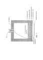
[0019] Фиг. 1 представляет собой график зависимости силы акустического излучения, силы тяжести/выталкивающей силы и влекущей силы Стокса от размера частиц, при этом горизонтальная ось имеет размерность в микронах (мкм), вертикальная - в ньютонах (Н).[0019] FIG. 1 is a graph of the dependence of the acoustic radiation force, gravity / buoyancy force, and Stokes attracting force on particle size, with the horizontal axis having a dimension in microns (μm), the vertical axis in newtons (N).
[0020] Фиг. 2 иллюстрирует общую конфигурацию пьезоэлектрического элемента, отделенного слоем воды от отражающего граничного слоя.[0020] FIG. 2 illustrates the general configuration of a piezoelectric element separated by a layer of water from a reflective boundary layer.
[0021] Фиг. 3 иллюстрирует известный из уровня техники способ применения преобразователя и отражателя для генерации плоской стоячей волны для создания в акустической камере неплотно упакованные матрицы частиц. Приведены три изображения: вид со стороны отражателя, вид сверху и изометрическое изображение.[0021] FIG. 3 illustrates a prior art method of using a transducer and reflector to generate a plane standing wave to create loosely packed particle arrays in an acoustic chamber. Three images are shown: view from the reflector side, top view and isometric image.
[0022] Фиг. 4 иллюстрирует способ применения преобразователя и отражателя согласно настоящему изобретению для генерации многомерной акустической стоячей волны, чтобы создать в акустической камере плотно упакованные кластеры частиц. Приведены три изображения: вид со стороны отражателя, вид сверху и изометрическое изображение.[0022] FIG. 4 illustrates a method of using the transducer and reflector according to the present invention to generate a multidimensional acoustic standing wave to create densely packed particle clusters in an acoustic chamber. Three images are shown: view from the reflector side, top view and isometric image.
[0023] Фиг. 5 представляет собой диаграмму, иллюстрирующую акустофоретический способ отделения вторичной текучей среды или частиц, менее плотных, чем первичная текучая среда, согласно настоящему изобретнию.[0023] FIG. 5 is a diagram illustrating an acoustophoretic method for separating a secondary fluid or particles less dense than a primary fluid according to the present invention.
[0024] Фиг. 6 представляет собой диаграмму, иллюстрирующую акустофоретический способ отделения вторичной текучей среды или частиц, более плотных, чем первичная текучая среда, согласно настоящему изобретению.[0024] FIG. 6 is a diagram illustrating an acoustophoretic method for separating a secondary fluid or particles denser than a primary fluid according to the present invention.
[0025] Фиг. 7 представляет собой изображение поперечного разреза известного из уровня техники ультразвукового преобразователя.[0025] FIG. 7 is a cross-sectional view of a prior art ultrasonic transducer.
[0026] Фиг. 8 представляет собой изображение поперечного разреза ультразвукового преобразователя согласно настоящему изобретению, внутри которого имеется воздушный зазор, при этом отсутствуют опорный слой или пластина износа.[0026] FIG. 8 is a cross-sectional view of an ultrasonic transducer according to the present invention, within which there is an air gap, with no support layer or wear plate.
[0027] Фиг. 9 представляет собой изображение поперечного разреза ультразвукового преобразователя согласно настоящему изобретению, внутри которого имеется воздушный зазор, а также имеется опорный слой и пластина износа.[0027] FIG. 9 is a cross-sectional view of an ultrasonic transducer according to the present invention, within which there is an air gap, and there is also a support layer and a wear plate.
[0028] Фиг. 10 иллюстрирует смещение в плоскости и вне плоскости пьезоэлектрического кристалла, в котором присутствуют составные волны.[0028] FIG. 10 illustrates a displacement in the plane and outside the plane of a piezoelectric crystal in which composite waves are present.
[0029] Фиг. 11 представляет аналитические данные об ответном смещении пьезоэлектрического кристалла PZT-8 (PZT, lead zirconate titanate - цирконат-титанат свинца) 25,4×25,4×1 мм с излучающим слоем воды.[0029] FIG. 11 presents analytical data on the reciprocal displacement of a PZT-8 piezoelectric crystal (PZT, lead zirconate titanate - lead zirconate titanate) 25.4 × 25.4 × 1 mm with a radiating water layer.
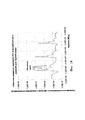
[0030] Фиг. 12 иллюстрирует аналитические данные об ответном смещении пьезоэлектрического кристалла PZT-8 25,4×25,4×1 мм с акустической камерой 25,4 мм, на конце которой расположен акустический отражатель.[0030] FIG. 12 illustrates analytical data on the reciprocal bias of a PZT-8 25.4 × 25.4 × 1 mm piezoelectric crystal with a 25.4 mm acoustic chamber at the end of which an acoustic reflector is located.
[0031] Фиг. 13 иллюстрирует двумерную численную модель COMSOL пьезоэлектрических уравнений в соответствии с данным изобретением.[0031] FIG. 13 illustrates a two-dimensional numerical model of the COMSOL piezoelectric equations in accordance with this invention.
[0032] Фиг. 14 иллюстрирует численные данные об ответном смещении пьезоэлектрического кристалла PZT-8 25,4×25,4×1 мм с камерой для текучей среды 25,4 мм, на конце которой расположен акустический отражатель.[0032] FIG. 14 illustrates numerical data on the reciprocal displacement of a PZT-8 25.4 × 25.4 × 1 mm piezoelectric crystal with a 25.4 mm fluid chamber at the end of which is an acoustic reflector.
[0033] Фиг. 15 иллюстрирует численные данные об ответном токе пьезоэлектрического кристалла PZT-8 25,4×25,4×1 мм с камерой для текучей среды 25,4 мм, на конце которой расположен акустический отражатель.[0033] FIG. 15 illustrates numerical data on the response current of a PZT-8 25.4 × 25.4 × 1 mm piezoelectric crystal with a 25.4 mm fluid chamber at the end of which is an acoustic reflector.
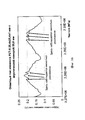
[0034] Фиг. 16 иллюстрирует экспериментальные данные об ответном токе пьезоэлектрического кристалла PZT-8 25,4×25,4×1 мм, работающего с колебанием частоты 30 кГц и снабженного акустической камерой 25,4 мм, на конце которой расположен акустический отражатель.[0034] FIG. 16 illustrates the experimental data on the response current of a PZT-8 25.4 × 25.4 × 1 mm piezoelectric crystal operating with a frequency oscillation of 30 kHz and provided with an acoustic chamber of 25.4 mm, at the end of which an acoustic reflector is located.
Осуществление изобретенияThe implementation of the invention
[0035] Настоящее изобретение может быть лучше понято из нижеследующего описания со ссылкой на подробное описание предпочтительных вариантов осуществления и включенных в него примеров. В нижеследующем описании и формуле изобретения встречаются ссылки на ряд терминов, которые следует трактовать следующим образом.[0035] The present invention can be better understood from the following description with reference to a detailed description of preferred embodiments and examples included therein. In the following description and claims, there are references to a number of terms, which should be interpreted as follows.
[0036] Хотя для ясности в нижеследующем описании используются специальные термины, эти термины предназначены для обозначения только конкретной структуры вариантов осуществления, выбранных для иллюстрации на чертежах, и не предназначены для определения или ограничения объема изобретения. Очевидно, что на чертежах и в нижеследующем описании одинаковые числовые обозначения относятся к компонентам, имеющим аналогичную функцию.[0036] Although specific terms are used in the following description for clarity, these terms are intended to indicate only the specific structure of the embodiments selected to illustrate the drawings, and are not intended to define or limit the scope of the invention. Obviously, in the drawings and in the following description, the same reference numerals refer to components having a similar function.
[0037] Упоминание в единственном числе включает в себя также ссылку и на множественное число, если из контекста очевидным образом не следует обратное.[0037] Mention in the singular also includes a reference to the plural, unless the context clearly indicates otherwise.
[0038] Термин "содержит" используется здесь как требующий наличия названного компонента и допускающий наличия других компонентов. Значение термина "содержит" включает в себя значения термина "состоит из", допускающий наличие только названного компонента, вместе с любыми примесями, возникшими в результате производства названного компонента.[0038] The term "comprises" is used here as requiring the presence of the named component and allowing the presence of other components. The meaning of the term “comprises” includes the meanings of the term “consists of”, allowing the presence of only the named component, together with any impurities resulting from the production of the named component.
[0039] Следует понимать, что числовые значения включают числовые значения, одинаковые при уменьшении до одинакового числа значимых цифр, и числовые значения, отличающиеся от указанного значения менее чем на величину экспериментальной погрешности обычной измерительной техники, описанной в настоящей заявке для определения этого значения.[0039] It should be understood that numerical values include numerical values that are the same when reduced to the same number of significant digits, and numerical values that differ from the indicated value by less than the experimental error of the conventional measuring technique described in this application to determine this value.
[0040] Все диапазоны, представленные в настоящем документе, включают в себя указанное предельное значение и могут комбинироваться независимо друг от друга (например, диапазон "от 2 до 10 грамм" включает в себя предельные значения, то есть, 2 грамма, 10 грамм и все промежуточные значения). Границы диапазонов и любые раскрытые здесь значения не ограничены точным интервалом или значением; они являются достаточно неопределенными для того, чтобы включать значения, близкие к этим диапазонам и/или значениям.[0040] All ranges presented herein include the specified limit value and can be combined independently of each other (for example, the "2 to 10 grams" range includes limit values, that is, 2 grams, 10 grams and all intermediate values). Range boundaries and any values disclosed herein are not limited to the exact range or value; they are uncertain enough to include values close to these ranges and / or values.
[0041] Определение "приблизительно", применяемое в отношении количества, включает названную величину и имеет значение, определенное контекстом. При использовании в контексте интервала определение "приблизительно" также следует трактовать как интервал, определенный абсолютными значениями двух границ. Например, интервал "от приблизительно 2 до приблизительно 10" также раскрывает интервал "от 2 до 10". Термин "приблизительно" может относиться к значению плюс или минус 10% от указанного числа. Например, "приблизительно 10%" может означать интервал от 9 до 11%, а "приблизительно 1" может означать "от 0,9 до 1,1".[0041] The definition of "approximately" as applied to quantity includes the named value and has a value defined by context. When used in the context of an interval, the definition of “approximately” should also be interpreted as the interval defined by the absolute values of the two boundaries. For example, the range from about 2 to about 10 also discloses the range from 2 to 10. The term "approximately" may refer to a value of plus or minus 10% of the specified number. For example, “approximately 10%” may mean a range of 9 to 11%, and “approximately 1” may mean “0.9 to 1.1.”
[0042] Следует отметить, что многие термины, используемые здесь, являются относительными. Например, термины "верхний" и "нижний" рассматриваются в отношении положения относительно друг друга, то есть, в данной ориентации верхний компонент расположен на более высоком уровне, чем нижний компонент, но если устройство перевернуто, эти термины могут измениться. Термины "впускное отверстие" и "выпускное отверстие" относятся к текучей среде, протекающей через них относительно данной конструкции. Например, текучая среда течет в конструкцию через впускное отверстие и вытекает из конструкции через выпускное отверстие. Термины "выше по потоку» и "ниже по потоку" относятся к направлению, в котором текучая среда протекает через различные компоненты, то есть, текучая среда сначала протекает через компонент выше по потоку, а затем - через компонент, расположенный ниже по потоку. Следует отметить, что в замкнутой системе первый компонент можно описать как находящийся относительно второго компонента как выше по потоку, так и ниже по потоку.[0042] It should be noted that many of the terms used here are relative. For example, the terms “upper” and “lower” are considered in relation to a position relative to each other, that is, in this orientation the upper component is located at a higher level than the lower component, but if the device is turned upside down, these terms may change. The terms “inlet” and “outlet” refer to a fluid flowing through them with respect to a given structure. For example, fluid flows into the structure through the inlet and flows out of the structure through the outlet. The terms “upstream” and “downstream” refer to the direction in which the fluid flows through the various components, that is, the fluid first flows through the upstream component, and then through the downstream component. note that in a closed system, the first component can be described as being relative to the second component both upstream and downstream.
[0043] Термины "горизонтальный" и "вертикальный" используются для указания направления относительно абсолютного начала отсчета, то есть, уровня земли. Однако эти термины не следует толковать, как требующие, чтобы структуры были абсолютно параллельными или абсолютно перпендикулярными друг другу. Например, первая вертикальная структура и вторая вертикальная структура не обязательно параллельны друг другу. Термины "верх" и "низ" или "основание" используются для обозначения поверхностей, когда относительно абсолютного начала отсчета, т.е. уровня земли, верх всегда расположен выше, чем низ/основание. Термины "вверх" и "вниз" также относятся к абсолютному началу отсчета; вверх всегда обозначает направление против силы тяжести земли.[0043] The terms "horizontal" and "vertical" are used to indicate directions relative to an absolute reference point, that is, ground level. However, these terms should not be construed as requiring that the structures be absolutely parallel or absolutely perpendicular to each other. For example, the first vertical structure and the second vertical structure are not necessarily parallel to each other. The terms “top” and “bottom” or “base” are used to indicate surfaces when relative to an absolute reference point, i.e. ground level, the top is always higher than the bottom / bottom. The terms "up" and "down" also refer to the absolute origin; up always indicates the direction against the gravity of the earth.
[0044] Термин "параллельный" следует понимать в смысле расположения двух поверхностей, между которыми сохраняется, в целом, постоянное расстояние, а не в том строгом математическом смысле, что при продолжении этих поверхностей до бесконечности они никогда не пересекаются.[0044] The term "parallel" should be understood in the sense of the location of two surfaces between which a constant distance is generally maintained, and not in the strict mathematical sense that, when these surfaces continue to infinity, they never intersect.
[0045] В настоящей заявке имеются ссылки на "тот же порядок величины". Два числа имеют тот же порядок величины, если частное от деления большего числа на меньшее число, составляет не менее 1, но меньше 10.[0045] This application refers to "the same order of magnitude." Two numbers have the same order of magnitude if the quotient of dividing a larger number by a smaller number is at least 1, but less than 10.
[0046] Акустофорез - это процесс отделения частиц и вторичных текучих сред от первичной или основной текучей среды с использованием акустических стоячих волн высокой интенсивности и без использования мембран или механических фильтров для отделения по размерам. Известно, что акустические стоячие волны высокой интенсивности прикладывают силу к частицам в текучей среде, когда присутствует разность плотности и/или сжимаемости, также известная как коэффициент акустического контраста. Профиль давления в стоячей волне содержит области локальных минимумов амплитуды давления в ее узлах и локальных максимумов в ее пучностях. В зависимости от плотности и сжимаемости частиц они захватываются в узлах или пучностях стоячей волны. В целом, чем выше частота стоячей волны, тем меньше частицы, которые могут быть захвачены давлением стоячей волны.[0046] Acoustophoresis is the process of separating particles and secondary fluids from a primary or primary fluid using high-intensity acoustic standing waves and without the use of membranes or mechanical filters to separate by size. High intensity acoustic standing waves are known to exert force on particles in a fluid when a difference in density and / or compressibility is present, also known as the acoustic contrast coefficient. The pressure profile in a standing wave contains the regions of local minima of the pressure amplitude at its nodes and local maxima at its antinodes. Depending on the density and compressibility of the particles, they are captured at the nodes or antinodes of the standing wave. In general, the higher the frequency of the standing wave, the smaller the particles that can be captured by the pressure of the standing wave.
[0047] При распространении в жидкостях акустических стоячих волн быстрые колебания могут генерировать неколеблющуюся силу на частицах, взвешенных в жидкости, или на поверхности раздела между жидкостями. Эта сила известна как сила акустического излучения. Эта сила является результатом нелинейности распространяющейся волны. В результате нелинейности волна искажается по мере ее распространения, при этом ее среднее во времени значение отлично от нуля. При последовательном расширении (в соответствии с теорией возмущений) первым ненулевым членом является член второго порядка, учитывающий силу акустического излучения. Сила акустического излучения на частице или клетке в жидкой суспензии зависит от разности давлений излучения с двух сторон этой частицы или клетки. Физическая характеристика силы излучения представляет собой наложение падающей волны и рассеянной волны, в дополнение к эффекту нежесткой частицы, колеблющейся с другой скоростью по сравнению с окружающей средой и поэтому излучающей волну. Следующее уравнение представляет собой аналитическое выражение для силы акустического излучения, действующую на частицу или клетку в жидкой суспензии в плоской стоячей волне.[0047] When acoustic standing waves propagate in liquids, rapid oscillations can generate a non-oscillating force on particles suspended in the liquid or on the interface between the liquids. This force is known as the strength of acoustic radiation. This force is the result of the nonlinearity of the propagating wave. As a result of nonlinearity, the wave is distorted as it propagates, while its average value in time is nonzero. In sequential expansion (in accordance with the perturbation theory), the first nonzero term is a second-order term that takes into account the strength of acoustic radiation. The strength of the acoustic radiation on a particle or cell in a liquid suspension depends on the difference in radiation pressure from two sides of the particle or cell. The physical characteristic of the radiation force is the superposition of the incident wave and the scattered wave, in addition to the effect of a non-rigid particle oscillating at a different speed compared to the environment and therefore emitting the wave. The following equation is an analytical expression for the strength of acoustic radiation acting on a particle or cell in a liquid suspension in a plane standing wave.

где βm - сжимаемость текучей среды, ρ - плотность, ϕ - коэффициент акустического контраста, Vp - объем частицы, λ - длина волны, k - это 2π/λ, P0 - амплитуда акустического давления, x - осевое расстояние вдоль стоячей волны (то есть, в направлении, перпендикулярном волновому фронту), причемwhere β m is the compressibility of the fluid, ρ is the density, ϕ is the acoustic contrast coefficient, V p is the particle volume, λ is the wavelength, k is 2π / λ, P 0 is the amplitude of the acoustic pressure, x is the axial distance along the standing wave (i.e., in a direction perpendicular to the wave front), and

где ρp - плотность частицы, ρm - плотность текучей среды, βp - сжимаемость частицы, βm - сжимаемость текучей среды.where ρ p is the particle density, ρ m is the density of the fluid, β p is the compressibility of the particle, β m is the compressibility of the fluid.
[0048] Для многомерной стоячей волны сила акустического излучения представляет собой трехмерное силовое поле, и одним из способов расчета этой силы является метод Горькова, в соответствии с которым первичную силу FR акустического излучения определяют как функцию потенциала поля U, Fv=-∇(U), где потенциал поля U определяется как[0048] For a multidimensional standing wave, the acoustic radiation force is a three-dimensional force field, and one of the methods for calculating this force is the Gorkov method, according to which the primary acoustic radiation force F R is determined as a function of the field potential U, F v = -∇ ( U), where the potential of the field U is defined as

тогда как f1 и f2 - монопольные и дипольные вклады, определяемые по формуламwhile f1 and f2 are monopoly and dipole contributions determined by the formulas
![]()
![]()
гдеWhere

где p - акустическое давление, u - скорость частиц жидкости, Λ - отношение плотности ρp клеток к плотности ρf текучей среды, σ - отношение скорости ср звука в клетке к скорости cf звука в текучей среде, Vo - объем клетки, а <> означает усреднение по времени в течение периода волны.where p is the acoustic pressure, u is the velocity of the fluid particles, Λ is the ratio of the density ρ p of the cells to the density ρ f of the fluid, σ is the ratio of the speed c p of sound in the cell to the speed c f of sound in the fluid, V o is the volume of the cell, and <> means averaging over time during the wave period.
[0049] Модель Горькова относится к одной частице в стоячей волне и ограничена размерами частицы, которые малы относительно длины волны акустических полей в текучей среде и частице. Она также не учитывает влияние вязкости текучей среды и частицы на силу излучения. В результате эта модель не может использоваться для крупных ультразвуковых сепараторов, поскольку в них могут образоваться довольно крупные кластеры частиц.[0049] The Gorkov model refers to a single particle in a standing wave and is limited by particle sizes that are small relative to the wavelength of the acoustic fields in the fluid and the particle. It also does not take into account the effect of the viscosity of the fluid and the particle on the radiation force. As a result, this model cannot be used for large ultrasonic separators, since rather large clusters of particles can form in them.
[0050] Фиг. 1 представляет собой график с логарифмическим масштабом на обоих осях (логарифмическая ось X, логарифмическая ось Y), показывающий соотношение между силой акустического излучения, влекущей силой потока текучей среды и выталкивающей силой, и радиусом частицы. Расчеты выполнены для типичной клетки млекопитающих, используемой в экспериментах. В этом эксперименте клетка млекопитающего имеет плотность (ρp) 1050 кг/м3, скорость (ср) звука в клетке составляет 1550 м/с. Текучая среда, в которой двигалась частица, представляет собой воду, имеющую плотность (ρw) 1000 кг/м3, скорость (cf) звука в текучей среде 1500 м/с, причем скорость (vf) потока составляла 4 см/мин. В ходе эксперимента использовали 33 пьезоэлектрических кристаллов PZT-8, возбуждаемые с частотой (f) 2,2 МГц при давлении (p) 1 МПа. Как пояснено выше, сила тяжести/выталкивающая сила зависит от объема частицы и поэтому она пренебрежимо мала для частиц с размером порядка микрона, но увеличивается и становится значимой для частицы с размером порядка сотен микрон. Влекущая сила потока текучей среды линейно зависит от скорости текучей среды и, следовательно, как правило, превышает выталкивающую силу для частиц размера порядка микрона, но пренебрежимо мала для частиц большего размера порядка сотен микрон. Сила акустического излучения соотносится с размерами частицы иным образом. Когда размер частицы невелик, уравнение Горькова является точным, а сила акустического захвата пропорциональна объему частицы. В результате, с увеличением размера частицы сила акустического излучения не увеличивается с кубом радиуса частицы и быстро стремится к нулю при определенном критическом размере частиц. При дальнейшем увеличении размера частицы сила излучения снова возрастает по величине, но с противоположной фазой (на графике это не показано). Эта картина повторяется при увеличении размеров частицы.[0050] FIG. 1 is a graph with a logarithmic scale on both axes (logarithmic axis X, logarithmic axis Y) showing the relationship between the strength of the acoustic radiation, the attracting force of the fluid flow and the buoyancy force, and the radius of the particle. Calculations were performed for a typical mammalian cell used in experiments. In this experiment, a mammalian cell has a density (ρ p ) of 1050 kg / m 3 , the speed (s p ) of sound in the cell is 1550 m / s. The fluid in which the particle was moving is water having a density (ρ w ) of 1000 kg / m 3 , the speed (c f ) of sound in the fluid is 1500 m / s, the flow velocity (v f ) being 4 cm / min . During the experiment, 33 PZT-8 piezoelectric crystals were used, excited with a frequency (f) of 2.2 MHz at a pressure (p) of 1 MPa. As explained above, gravity / buoyancy depends on the volume of the particle and therefore it is negligible for particles with a size of the order of a micron, but increases and becomes significant for a particle with a size of the order of hundreds of microns. The attracting force of the fluid flow is linearly dependent on the speed of the fluid and, therefore, typically exceeds the buoyancy force for particles of the order of microns in size, but is negligible for particles of a larger size of the order of hundreds of microns. The strength of acoustic radiation is related to the particle size in a different way. When the particle size is small, the Gorkov equation is accurate, and the force of acoustic capture is proportional to the volume of the particle. As a result, with increasing particle size, the strength of acoustic radiation does not increase with the cube of the particle radius and quickly tends to zero at a certain critical particle size. With a further increase in the particle size, the radiation force again increases in magnitude, but with the opposite phase (this is not shown in the graph). This pattern repeats with increasing particle size.
[0051] Вначале, когда через систему протекает суспензия с мелкими частицами преимущественно микронного размера, необходимо, чтобы сила акустического излучения уравновешивала комбинированное действие влекущей силы потока текучей среды и выталкивающей силы для того, чтобы частица была захвачена стоячей волной. На фиг. 1 это происходит при размере частиц приблизительно 3,5 микрон, обозначенном Rc1. Кроме того, как видно на графике, также будут захвачены все более крупные частицы. Поэтому, когда мелкие частицы захватываются в стоячей волне, происходит коалесценция/накопление/агрегация/агломерация, что приводит к непрерывному росту эффективного размера частиц. По мере роста размера частиц сила акустического излучения отражается от частицы, поэтому большие частицы будут вызывать уменьшение силы акустического излучения. Рост размера частиц продолжается до тех пор, пока выталкивающая сила не станет превалирующей, что показывает второй критический размер Rc2 частиц, при котором размер частиц будет увеличиваться или уменьшаться, в зависимости от их плотности по отношению к первичной текучей среде. Таким образом, на фиг. 1 показано, как мелкие частицы могут непрерывно захватываться в стоячей волне, вырастать в более крупные частицы или агрегаты, а затем в результате подниматься или осаждаться из-за увеличенной выталкивающей силы.[0051] Initially, when a suspension with small particles of predominantly micron size flows through the system, it is necessary that the acoustic radiation force balance the combined effect of the attracting force of the fluid flow and the buoyancy force so that the particle is trapped by a standing wave. In FIG. 1 this occurs at a particle size of approximately 3.5 microns, denoted by R c1 . In addition, as can be seen in the graph, larger particles will also be captured. Therefore, when small particles are captured in a standing wave, coalescence / accumulation / aggregation / agglomeration occurs, which leads to a continuous increase in the effective particle size. As the particle size increases, the strength of the acoustic radiation is reflected from the particle, so large particles will cause a decrease in the strength of the acoustic radiation. Particle size growth continues until the buoyancy force becomes prevailing, which shows a second critical particle size R c2 at which the particle size will increase or decrease, depending on their density with respect to the primary fluid. Thus, in FIG. Figure 1 shows how small particles can continuously be captured in a standing wave, grow into larger particles or aggregates, and then rise or precipitate as a result of increased buoyancy.
[0052] Существует потребность в использовании более сложной и совершенной модели, чем модель сил акустического излучения, которая не ограничена размером частиц, как модель Горькова. Модели, которые были реализованы в настоящем изобретении, основаны на теоретических работах Юрия Ильинского и Евгении Заболоцкой, описанных в документе AIP Conference Proceedings, Vol. 1474-1, pp. 255-258 (2012). Эти модели также включают влияние вязкости текучей среды и частиц, следовательно, они обеспечивают более точное вычисление силы акустического излучения. На фиг. 2 показана весьма общая конфигурация пьезоэлектрика с электродами, расположенными на его наружных поверхностях. Один электрод сконфигурирован как электрод с периодическим электрическим потенциалом, в то время как другой электрод сконфигурирован как заземляющий электрод. Пьезоэлектрик расположен напротив акустического отражателя, обеспечивающего граничное условие в отношении отражения. Отражатель и пьезоэлектрик разделены слоем воды. Общее представление пьезоэлектрических уравнений:[0052] There is a need to use a more complex and advanced model than the acoustic radiation force model, which is not limited by particle size, like the Gorkov model. The models that were implemented in the present invention are based on the theoretical work of Yuri Ilyinsky and Evgeny Zabolotskaya described in AIP Conference Proceedings, Vol. 1474-1, pp. 255-258 (2012). These models also include the effects of fluid viscosity and particles, therefore they provide a more accurate calculation of the strength of acoustic radiation. In FIG. Figure 2 shows a very general configuration of a piezoelectric with electrodes located on its outer surfaces. One electrode is configured as an electrode with periodic electric potential, while the other electrode is configured as an earth electrode. The piezoelectric is located opposite the acoustic reflector, providing a boundary condition with respect to reflection. The reflector and piezoelectric are separated by a layer of water. General representation of piezoelectric equations:


где p - плотность, ω - угловая частота, u - тензор смещения, ϕ - потенциал электрического поля, λ - тензор упругости, е - тензор связи, ε - тензор диэлектрической проницаемости. На основе этого общего представления предполагаемыми решениями пьезоэлектрических уравнений являются следующие выражения:where p is the density, ω is the angular frequency, u is the displacement tensor, ϕ is the electric field potential, λ is the elastic tensor, e is the bond tensor, ε is the dielectric constant. Based on this general view, the following expressions are the intended solutions of the piezoelectric equations:
![]()
![]()
![]()
![]()
где ![]()
![]()
![]()
![]()
[0053] Механические граничные условия определяются следующими уравнениями:[0053] The mechanical boundary conditions are determined by the following equations:


где σ - напряжение, dz - толщина пьезоэлектрического элемента, pw - акустическое давление в воде, ρw - плотность воды, kw - волновое число в воде, KR - коэффициент отражения, L - длина слоя воды.where σ is the voltage, d z is the thickness of the piezoelectric element, p w is the acoustic pressure in water, ρ w is the density of water, k w is the wave number in water, K R is the reflection coefficient, L is the length of the water layer.
[0054] Электрические граничные условия определяются следующими уравнениями:[0054] The electrical boundary conditions are determined by the following equations:
![]()
![]()
ϕ(x, y, z=0)=0ϕ (x, y, z = 0) = 0
где V - амплитуда напряжения, n - периодический индекс, m - периодический индекс для представляющей интерес моды (n, m).where V is the voltage amplitude, n is the periodic index, m is the periodic index for the mode of interest (n, m).
[0055] Способе акустофоретического разделения согласно настоящему изобретнию используют многомерные ультразвуковые акустические стоячие волны, плоские акустические стоячие волны или комбинацию, то есть, наложение, плоских и многомерных акустических стоячих волн (в совокупности называемых в настоящем документе акустическими стоячими волнами) для захвата частиц или вторичной текучей среды в объеме текучей среды, содержащей эти частицы или эту вторичную текучую среду.[0055] The acoustophoretic separation method of the present invention uses multidimensional ultrasonic standing waves, plane acoustic standing waves, or a combination, that is, superimposing, plane and multidimensional acoustic standing waves (collectively referred to as acoustic standing waves) to capture particles or secondary fluid in the volume of the fluid containing these particles or this secondary fluid.
[0056] На фиг. 3 проиллюстрирован известный из уровня техники способ применения расположенных друг против друга преобразователя и отражателя для генерации между ними плоской стоячей волны. В левой части фиг. 3 представлено изображение акустической камеры, как она видна через отражатель, в то время как средняя часть фиг. 3 представляет собой вид акустической камеры на виде сверху. Как показано на фиг. 3, генерация плоской стоячей волны в акустической камере обеспечивает создание в акустической камере неплотно заполненных плоскостей частиц, как правило, для частиц с положительным акустическим контрастом соответствующих узловым плоскостям давления.[0056] FIG. 3 illustrates a method known in the art for applying a transducer and a reflector arranged against each other to generate a plane standing wave between them. On the left side of FIG. 3 is an image of an acoustic chamber as seen through a reflector, while the middle part of FIG. 3 is a plan view of an acoustic chamber. As shown in FIG. 3, the generation of a plane standing wave in an acoustic chamber ensures the creation of loosely filled particle planes in the acoustic chamber, as a rule, for particles with a positive acoustic contrast corresponding to nodal pressure planes.
[0057] С другой стороны, на фиг. 4 проиллюстрирован новый способ применения преобразователя и отражателя, расположенных друг против друга, для генерации между ними многомерной акустической стоячей волны или наложение многомерных акустических стоячих волн. Как и в случае фиг. 3, в левой части фиг. 4 представлено изображение акустической камеры, как она видна через отражатель, в то время как средняя часть фиг. 4 представляет собой вид акустической камеры на виде сверху. Как показано на фиг. 4, генерация многомерной акустической стоячей волны в акустической камере обеспечивает создание в акустической камере плотно упакованных кластеров частиц, как правило, соответствующих местоположению узлов давления или пучностей давления в плоской волне в зависимости от коэффициента акустического контраста.[0057] On the other hand, in FIG. 4 illustrates a new method of using the transducer and the reflector, located opposite each other, to generate a multidimensional acoustic standing wave between them or to superimpose multidimensional acoustic standing waves. As in the case of FIG. 3, on the left side of FIG. 4 is an image of an acoustic chamber as seen through a reflector, while the middle part of FIG. 4 is a plan view of an acoustic chamber. As shown in FIG. 4, the generation of a multidimensional acoustic standing wave in an acoustic chamber ensures the creation of densely packed clusters of particles in the acoustic chamber, usually corresponding to the location of pressure nodes or pressure antinodes in a plane wave, depending on the acoustic contrast coefficient.
[0058] Частицы или вторичная текучая среда накапливаются в узлах или пучностях акустической стоячей волны в зависимости от коэффициента акустического контраста частиц или вторичной текучей среды относительно первичной текучей среды, образуя кластеры/агрегаты/агломераты/коалесцированные капли, которые непрерывно выпадают из акустической стоячей волны, когда кластеры вырастают до размера, достаточно большого, чтобы преодолеть удерживающую силу акустической стоячей волны (например, путем слияния или агломерации), а плотность частиц/вторичной текучей среды больше, чем плотность первичной текучей среды, или поднимаются из акустической стоячей волны, если плотность частиц/вторичной текучей среды меньше, чем плотность первичной текучей среды. Сила акустического излучения пропорциональна объему частицы (например, кубу радиуса), если размеры частицы малы относительно длины волны. Она пропорциональна частоте и коэффициенту акустического контраста. Она также пропорциональна акустической энергии (например, квадрату амплитуды акустического давления). Для гармонического возбуждения синусоидальная пространственная вариация этой силы - это то, что приводит частицы в устойчивые положения в осевом направлении стоячих волн. Когда действующая на частицы сила акустического излучения сильнее, чем совокупный эффект влекущей сила потока текучей среды и выталкивающей силы, и силы тяжести, частица задерживается в поле акустической стоячей волны. Это приводит к концентрации, агломерации и/или слипанию задержанных частиц. Большие поперечные силы обеспечивают быструю кластеризацию частиц. Таким образом, частицы микронного размера, например, бактерии, клетки млекопитающих, микроводоросли, металлические частицы, дрожжи, грибы, липиды, капли масла, эритроциты, лейкоциты, тромбоциты и так далее, могут быть отделены от первичной жидкости за счет усиленного гравитационного разделения. Для случая суспензии с несколькими разными размерами частиц путем настройки параметров устройства может быть осаждена группа более крупных частиц, тогда как группу частиц меньшего размера может быть сохранена в суспензии. Затем эти два слоя могут быть отобраны отдельно. После этого могут использовать повторный процесс для фракционирования групп частиц разного размера в соответствии с размером. В этом отношении многомерные акустические стоячие волны, генерируемые каждым преобразователем, могут иметь разные частоты.[0058] Particles or secondary fluid accumulate in nodes or antinodes of an acoustic standing wave depending on the acoustic contrast ratio of the particles or secondary fluid relative to the primary fluid, forming clusters / aggregates / agglomerates / coalesced droplets that continuously fall out of the acoustic standing wave, when clusters grow to a size large enough to overcome the holding force of an acoustic standing wave (for example, by merging or agglomeration), and the particle density / sec ary fluid is greater than the density of the primary fluid, or the rise of the acoustic standing wave, if the particle density / secondary fluid is less than the density of the primary fluid. The strength of acoustic radiation is proportional to the volume of the particle (for example, a cube of radius) if the particle size is small relative to the wavelength. It is proportional to the frequency and coefficient of acoustic contrast. It is also proportional to acoustic energy (e.g., squared amplitude of acoustic pressure). For harmonic excitation, a sinusoidal spatial variation of this force is what brings the particles into stable positions in the axial direction of standing waves. When the acoustic radiation force acting on the particles is stronger than the combined effect of the entraining force of the fluid flow and the buoyancy force and gravity, the particle is trapped in the field of an acoustic standing wave. This leads to concentration, agglomeration and / or coalescence of trapped particles. Large transverse forces provide rapid clustering of particles. Thus, micron-sized particles, for example, bacteria, mammalian cells, microalgae, metal particles, yeast, fungi, lipids, oil droplets, red blood cells, white blood cells, platelets and so on, can be separated from the primary fluid due to enhanced gravitational separation. In the case of a suspension with several different particle sizes, a group of larger particles can be deposited by adjusting the device parameters, while a group of smaller particles can be stored in the suspension. Then these two layers can be selected separately. After that, a repeat process can be used to fractionate groups of particles of different sizes according to size. In this regard, the multidimensional acoustic standing waves generated by each transducer can have different frequencies.
[0059] Одной из специальных областей применения акустофоретического устройства является обработка получаемых в биореакторах материалов. Важно иметь возможность отделять относительно большие клетки и клеточный детрит от выделяемых материалов, находящихся в первичной текучей среде. Выделяемые материалы состоят из биомолекул, таких как рекомбинантные белки или моноклональные антитела, и являются желательным продуктом, подлежащим восстановлению. Благодаря использованию акустофореза отделение клеток и клеточного детрита весьма эффективно и приводит к очень малой потере выделяемых материалов. Это представляет собой усовершенствование по сравнению с современными процессами фильтрации (глубинное фильтрование, тангенциальная фильтрация и т.п.), которые показывают ограниченную эффективность при высоких плотностях клеток, так что потеря выделяемых материалов в самих фильтрующих слоях может составлять до 5% материалов, полученных в биореакторе. Использование клеточных культур млекопитающих, включая клетки яичников китайского хомяка (СНО), клетки гибридомы NS0, клетки почки новорожденного хомяка (ВНK), клетки насекомых и клетки человека (например, Т-лимфоциты, В-лимфоциты, стволовые клетки, эритроциты) и в целом живые/биологические клетки, оказалось очень эффективным способом получения/выделения рекомбинантных белков и моноклональных антител, необходимых для современных фармацевтических препаратов. Фильтрация клеток млекопитающих и клеточного детрита млекопитающих посредством акустофореза помогает значительно увеличить производительность биореактора. При желании процесс акустофореза также может быть связан со стандартным процессом фильтрации вверх или вниз по потоку, таким как глубинное фильтрование, тангенциальная фильтрация (Tangential Flow Filtration, TFF) или другие процессы механической фильтрации.[0059] One of the special applications of the acoustophoretic device is the processing of materials obtained in bioreactors. It is important to be able to separate relatively large cells and cell detritus from the excreted materials in the primary fluid. The materials recovered are composed of biomolecules, such as recombinant proteins or monoclonal antibodies, and are a desirable product to be reconstituted. Thanks to the use of acoustophoresis, the separation of cells and cellular detritus is very effective and leads to a very small loss of excreted materials. This represents an improvement over modern filtration processes (deep filtering, tangential filtering, etc.), which show limited efficiency at high cell densities, so that the loss of released materials in the filter layers themselves can amount to 5% of the materials obtained in bioreactor. The use of mammalian cell cultures, including Chinese hamster ovary (CHO) cells, NS0 hybridoma cells, newborn hamster kidney (BHK) cells, insect cells and human cells (e.g., T-lymphocytes, B-lymphocytes, stem cells, red blood cells) and in general living / biological cells have proven to be a very effective way to obtain / isolate the recombinant proteins and monoclonal antibodies needed for modern pharmaceuticals. Filtration of mammalian cells and mammalian cell detritus by means of acoustophoresis helps to significantly increase the bioreactor productivity. If desired, the acoustophoresis process can also be associated with a standard upstream or downstream filtration process, such as depth filtration, Tangential Flow Filtration (TFF) or other mechanical filtration processes.
[0060] В этом отношении коэффициент акустического контраста является функцией отношения сжимаемости частиц к сжимаемости текучей среды и отношения плотности частиц к плотности текучей среды. Большинство типов клеток имеют более высокую плотность и более низкую сжимаемость, чем среда, в которой они суспендированы, так что коэффициент акустического контраста между клетками и средой имеет положительную величину. В результате продольная сила акустического излучения (Acoustic Radiation Force, ARF) перемещает клетки с положительным коэффициентом контраста к плоскостям узлов давления, тогда как клетки или другие частицы с отрицательным коэффициентом контраста перемещаются к плоскостям пучностей давления. Радиальная или поперечная составляющая ARF больше, чем совокупный эффект влекущей силы потока текучей среды и силы тяжести. Радиальная или поперечная составляющая перемещает клетки/частицы в определенные места (области) в пределах этих плоскостей, где они группируются, скопляются, агломерируются или объединяются в более крупные группы, которые после этого под действием силы тяжести непрерывно отделяются от текучей среды.[0060] In this regard, the acoustic contrast coefficient is a function of the ratio of the compressibility of the particles to the compressibility of the fluid and the ratio of the density of the particles to the density of the fluid. Most cell types have a higher density and lower compressibility than the medium in which they are suspended, so that the coefficient of acoustic contrast between the cells and the medium is positive. As a result, the Acoustic Radiation Force (ARF) moves the cells with a positive contrast ratio to the planes of the pressure nodes, while the cells or other particles with a negative contrast coefficient move to the planes of the pressure antinodes. The radial or transverse component of ARF is greater than the combined effect of the entraining force of the fluid flow and gravity. The radial or transverse component moves the cells / particles to specific places (areas) within these planes, where they are grouped, accumulate, agglomerate or combine into larger groups, which are then continuously separated from the fluid by gravity.
[0061] Предпочтительно, чтобы ультразвуковой преобразователь (ультразвуковые преобразователи) генерировал (генерировали) в текучей среде трехмерную или многомерную акустическую стоячую волну, которая посредством поперечной силы воздействует на взвешенные частицы, чтобы поддержать продольную силу, чтобы улучшить эффективность стоячей волны в отношении захвата частиц и образования кластеров. Типовые результаты, опубликованные в литературе, показывают, что поперечная сила на два порядка меньше продольной силы. Технология, раскрытая в этой заявке, напротив, обеспечивает поперечную силу того же порядка величины, что и продольная сила (то есть многомерную акустическую стоячую волну). Однако в некоторых нижеописанных вариантах осуществления рассматриваются комбинации преобразователей, создающие как многомерные акустические стоячие волны, так и плоские стоячие волны. В контексте настоящего описания стоячая волна, при которой поперечная сила имеет тот же порядок величины, что и продольная сила, считается многомерной акустической стоячей волной.[0061] It is preferable that the ultrasonic transducer (ultrasonic transducers) generate (generate) a three-dimensional or multidimensional acoustic standing wave in the fluid, which, through the transverse force, acts on the suspended particles to maintain the longitudinal force in order to improve the efficiency of the standing wave with respect to particle capture and cluster formation. Typical results published in the literature show that the shear force is two orders of magnitude less than the longitudinal force. The technology disclosed in this application, on the contrary, provides a transverse force of the same order of magnitude as the longitudinal force (i.e., a multidimensional acoustic standing wave). However, in some of the embodiments described below, combinations of transducers are considered that produce both multidimensional acoustic standing waves and plane standing waves. In the context of the present description, a standing wave, in which the transverse force is of the same order of magnitude as the longitudinal force, is considered a multidimensional acoustic standing wave.
[0062] Иногда из-за акустического потока может потребоваться, модулировать частоту или амплитуду напряжения стоячей волны. Это могут сделать путем амплитудной и/или частотной модуляции. Для достижения определенных результатов улавливания материалов также может использоваться циклический режим распространения стоячей волны. Другими словами, для достижения желаемых результатов акустический луч могут включать и выключать с разными частотами.[0062] Sometimes, due to acoustic flow, it may be necessary to modulate the frequency or amplitude of the voltage of a standing wave. This can be done by amplitude and / or frequency modulation. To achieve certain results of the capture of materials can also be used in a cyclic mode of propagation of a standing wave. In other words, to achieve the desired results, the acoustic beam can be turned on and off at different frequencies.
[0063] Схематическое представление одного из вариантов осуществления изобретения для извлечения масла или другого материала, более легкого, чем вода, показано на фиг. 5. На преобразователь 10, как правило, подают частоту возбуждения в диапазоне от сотен килогерц до десятков мегагерц. Между преобразователем 10 и отражателем 11 создают одну или несколько стоячих волн. Микрокапли 12 задерживают в стоячей волне в пучностях 14 давления, где они агломерируют, агрегируют, образуют кластеры или коалесцируют и, в случае плавучего материала, всплывают на поверхность и удаляются через выпускное отверстие 16, расположенное выше канала для текучей среды. Осветленную воду выпускают через выпускное отверстие 18. Технология акустофоретического разделения позволяет выполнять многокомпонентное разделение частиц без неполадок и со значительно меньшими затратами.[0063] A schematic representation of one embodiment of the invention for recovering oil or other material lighter than water is shown in FIG. 5. As a rule, an excitation frequency in the range from hundreds of kilohertz to tens of megahertz is supplied to the
[0064] Схематическое представление одного из вариантов осуществления изобретения для извлечения примесей или другого материала, более тяжелого, чем вода, показано на фиг. 6. На преобразователь 10, как правило, подают частоту возбуждения в диапазоне от сотен килогерц до десятков мегагерц. Примеси в поступающей воде 13 задерживают в стоячей волне в узлах 15 давления, где они агломерируют, агрегируют, образуют кластеры или слипаются и, в случае более тяжелого материала, опускаются на дно накопителя и удаляются через выпускное отверстие 17, расположенное ниже канала для текучей среды. Осветленную воду выпускают через выпускное отверстие 18.[0064] A schematic representation of one embodiment of the invention for recovering impurities or other material heavier than water is shown in FIG. 6. As a rule, an excitation frequency in the range from hundreds of kilohertz to tens of megahertz is supplied to the
[0065] Как объяснялось выше, ультразвуковой преобразователь и отражатель расположены на противоположных сторонах акустической камеры. Таким образом, между ультразвуковым преобразователем и отражателем создают одну или несколько акустических стоячих волн.[0065] As explained above, the ultrasonic transducer and the reflector are located on opposite sides of the acoustic chamber. Thus, between the ultrasonic transducer and the reflector create one or more acoustic standing waves.
[0066] Перед раскрытием дальнейшей оптимизации устройства, следует пояснить, каким образом генерируются многомерные акустические стоячие волны. Многомерную акустическую стоячую волну, необходимую для сбора частиц, получают путем возбуждения ультразвукового преобразователя на частоте генерирования акустической стоячей волны и возбуждения основной моды трехмерных колебаний пьезоэлектрического элемента преобразователя. Возмущение пьезоэлектрического элемента в ультразвуковом преобразователе в многомодовом режиме позволяет генерировать многомерную акустическую стоячую волну. Пьезоэлектрический элемент может специально быть выполнен с возможностью деформации в многомодовом режиме на заданных частотах, что позволяет генерировать многомерную акустическую стоячую волну. Многомерную акустическую стоячую волну могут генерировать, применяя различные моды пьезоэлектрического элемента, например, моду 3×3, позволяющую генерировать многомерные акустические стоячие волны. Множество многомерных акустических стоячих волн также могут генерировать, позволяя пьезоэлектрическому элементу вибрировать с несколькими разными формами колебаний. Таким образом, этот элемент может возбуждать несколько мод, таких как мода 0×0 (то есть, поршневая мода), до 1×1 (мода низшего порядка), до 2×2, 1×3, 3×1, 3×3 и других мод более высокого порядка, а затем циклически возвращаться через более низкие моды элемента (не обязательно в прямом порядке). Это переключение или возбуждение пьезоэлектрического элемента в разных модах делает возможными различные многомерные формы мод, а также форму поршневой моды, генерируемые в течение определенного времени.[0066] Before disclosing further optimization of the device, it should be explained how multidimensional acoustic standing waves are generated. The multidimensional acoustic standing wave necessary for collecting particles is obtained by exciting an ultrasonic transducer at a frequency of generating an acoustic standing wave and exciting the fundamental three-dimensional mode of the piezoelectric transducer element. Perturbation of the piezoelectric element in the ultrasonic transducer in multimode mode allows you to generate a multidimensional acoustic standing wave. The piezoelectric element can be specially made with the possibility of deformation in multimode mode at given frequencies, which allows you to generate a multidimensional acoustic standing wave. A multidimensional acoustic standing wave can be generated using various modes of the piezoelectric element, for example, a 3 × 3 mode, which allows generating multidimensional acoustic standing waves. Many multidimensional acoustic standing waves can also be generated, allowing the piezoelectric element to vibrate with several different waveforms. Thus, this element can excite several modes, such as the 0 × 0 mode (i.e., the piston mode), up to 1 × 1 (lower order mode), up to 2 × 2, 1 × 3, 3 × 1, 3 × 3 and other higher order modes, and then cycle back through the lower modes of the element (not necessarily in the direct order). This switching or excitation of the piezoelectric element in different modes makes possible various multidimensional forms of the modes, as well as the shape of the piston mode, generated over time.
[0067] Кроме того, могут возбудить или выбрать частоту возбуждения, одновременно возбуждающую несколько мод, причем каждая мода имеет разную амплитуду смещения. Благодаря этой комбинации нескольких мод, возбуждаемых одновременно с переменной амплитудой смещения, могут создать наложение многомерных стоячих волн, требуемых для захвата, кластеризации и отделения от первичной текучей среды вторичной текучей среды или частиц.[0067] In addition, they can excite or select an excitation frequency that simultaneously excites several modes, each mode having a different bias amplitude. Thanks to this combination of several modes, excited simultaneously with a variable amplitude of the bias, they can create the superposition of the multidimensional standing waves required for capturing, clustering, and separating the secondary fluid or particles from the primary fluid.
[0068] Рассеивание акустического поля от частиц обеспечивает трехмерную силу акустического излучения, действующую как трехмерное поле захвата. Сила акустического излучения пропорциональна объему частицы (например, кубу радиуса), если частица мала относительно длины волны, она пропорциональна частоте и коэффициенту акустического контраста и она также пропорциональна акустической энергии (например, квадрату амплитуды акустического давления). Когда сила акустического излучения, действующая на частицы, сильнее, чем совокупный эффект влекущей силы потока текучей среды и выталкивающей силы и силы тяжести, частицы задерживаются в поле акустической стоячей волны. Это приводит к концентрации, агломерации и/или слипанию задержанных частиц. Таким образом, относительно большие твердые частицы одного материала могут быть отделены от меньших частиц другого материала, того же материала и/или первичной текучей среды благодаря усиленному гравитационному разделению.[0068] The dispersion of the acoustic field from the particles provides a three-dimensional acoustic radiation force, acting as a three-dimensional capture field. The strength of acoustic radiation is proportional to the volume of the particle (for example, a cube of radius), if the particle is small relative to the wavelength, it is proportional to the frequency and coefficient of acoustic contrast and it is also proportional to acoustic energy (for example, the square of the amplitude of the acoustic pressure). When the force of acoustic radiation acting on the particles is stronger than the combined effect of the attracting force of the fluid flow and buoyancy and gravity, the particles are trapped in the field of an acoustic standing wave. This results in concentration, agglomeration and / or adhesion of trapped particles. Thus, relatively large solid particles of one material can be separated from smaller particles of another material of the same material and / or primary fluid due to enhanced gravitational separation.
[0069] Многомерная стоячая волна создает силы акустического излучения как в осевом направлении (то есть, в направлении стоячей волны, между преобразователем и отражателем, перпендикулярном направлению потока), так и в поперечном направлении (то есть, в направлении потока). По мере прохождения смеси через акустическую камеру на частицы в суспензии в направлении стоячей волны действует большая продольная составляющая силы. Поскольку эта акустическая сила перпендикулярна направлению потока и влекущей силе потока, она быстро перемещает частицы к узловым плоскостям или плоскостям пучностей, в зависимости от коэффициента контрастности частицы. Затем поперечная сила акустического излучения действует так, что она перемещает сконцентрированные частицы к центру каждого планарного узла, что приводит к агломерации или образованию кластеров. Чтобы такие агрегаты частиц постоянно росли, а затем выпадали в осадок из смеси благодаря силе тяжести, поперечная составляющая должна преодолевать влекущую силу потока. Следовательно, чтобы акустический сепаратор работал эффективно, необходимо учитывать как падение влекущей силы на одну частицу по мере увеличения размера кластера частиц, так и падение силы акустического излучения на каждую частицу при увеличении размера кластера частиц. В контексте настоящего описания поперечная составляющая силы и продольная составляющая силы многомерной акустической стоячей волны имеют одинаковый порядок величины. В этом отношении следует отметить, что в многомерной акустической стоячей волне осевая сила больше поперечной силы, но поперечная сила многомерной акустической стоячей волны намного больше, чем поперечная сила плоской стоячей волны, обычно на два порядка или больше.[0069] A multidimensional standing wave generates acoustic radiation forces both in the axial direction (that is, in the direction of the standing wave, between the transducer and the reflector perpendicular to the direction of flow) and in the transverse direction (that is, in the direction of flow). As the mixture passes through the acoustic chamber, a large longitudinal force component acts on the particles in the suspension in the direction of the standing wave. Since this acoustic force is perpendicular to the direction of flow and the attracting force of the stream, it quickly moves particles to nodal planes or planes of antinodes, depending on the contrast ratio of the particle. Then the transverse force of the acoustic radiation acts so that it moves the concentrated particles to the center of each planar assembly, which leads to agglomeration or the formation of clusters. In order for such particle aggregates to constantly grow and then precipitate from the mixture due to gravity, the transverse component must overcome the attracting force of the flow. Therefore, in order for the acoustic separator to work efficiently, it is necessary to take into account both the decrease in the attracting force per particle as the particle cluster size increases, and the decrease in the acoustic radiation force on each particle as the particle cluster size increases. In the context of the present description, the transverse component of the force and the longitudinal component of the force of a multidimensional acoustic standing wave are of the same order of magnitude. In this regard, it should be noted that in a multidimensional acoustic standing wave, the axial force is greater than the transverse force, but the transverse force of the multidimensional acoustic standing wave is much larger than the transverse force of a plane standing wave, usually two orders of magnitude or more.
[0070] Также следует привести некоторые пояснения относительно ультразвуковых преобразователей, применяемых в устройствах, системах и способах, предлагаемых в данном изобретении. В этом отношении в преобразователях используют пьезоэлемент, обычно изготовленный из PZT-8 (цирконат-титанат свинца). Такие элементы могут иметь поперечное сечение 1 дюйм и номинальную резонансную частоту 2 МГц, они могут иметь также больший размер. Каждый модуль ультразвукового преобразователя может иметь только один пьезоэлектрический элемент или несколько элементов, каждый из которых действует, как отдельный ультразвуковой преобразователь и управляется одним или несколькими усилителями. Пьезоэлектрический элемент (пьезоэлектрические элементы) могут быть кристаллическими, полукристаллическими или некристаллическими. Пьезоэлектрический элемент (пьезоэлектрические элементы) могут иметь квадратную форму, прямоугольную форму, форму неправильного многоугольника или, в целом, любую произвольную форму. Преобразователь (преобразователи) используют для создания поля давления, которое генерирует силы одинакового порядка величины, ориентированные как перпендикулярно направлению стоячей волны (в поперечном направлении), так и в направлении стоячей волны (в осевом направлении).[0070] You should also provide some explanations regarding the ultrasonic transducers used in the devices, systems and methods proposed in this invention. In this regard, the transducers use a piezoelectric element, usually made of PZT-8 (lead zirconate titanate). Such elements may have a cross section of 1 inch and a nominal resonant frequency of 2 MHz, they may also have a larger size. Each ultrasonic transducer module can have only one piezoelectric element or several elements, each of which acts as a separate ultrasonic transducer and is controlled by one or more amplifiers. The piezoelectric element (piezoelectric elements) can be crystalline, semi-crystalline or non-crystalline. The piezoelectric element (piezoelectric elements) may have a square shape, a rectangular shape, an irregular polygon shape, or, in general, any arbitrary shape. The transducer (s) are used to create a pressure field that generates forces of the same order of magnitude, oriented both perpendicular to the direction of the standing wave (in the transverse direction) and in the direction of the standing wave (in the axial direction).
[0071] Фиг. 7 представляет собой поперечный разрез обычного ультразвукового преобразователя. Этот преобразователь имеет пластину 50 износа, расположенную на нижнем конце, эпоксидный слой 52, пьезоэлектрический элемент 54 (например, керамический кристалл, например, изготовленный из PZT), слой 56 эпоксидной смолы и опорный слой 58. По обе стороны пьезоэлектрического элемента имеется электрод: положительный электрод 61 и отрицательный электрод 63. Слой 56 эпоксидной смолы предназначен для крепления опорного слоя 58 к пьезоэлектрическому элементу 54. Вся эта сборка содержится в корпусе 60, который может быть изготовлен, например, из алюминия. Электрический соединитель 62 обеспечивает соединение проводов, проходящих через корпус и соединяющихся с выводами (не показаны), присоединяемыми к пьезоэлектрическому элементу 54. Как правило, опорные слои предназначены для добавления затухания и создания широкополосного преобразователя с равномерным смещением в широком диапазоне частот, а также для подавления возбуждения в определенных модах собственных колебаний. Пластины износа обычно выполняют в виде трансформаторов импеданса, чтобы они лучше соответствовали характеристическому импедансу среды, в которую излучает преобразователь.[0071] FIG. 7 is a cross-sectional view of a conventional ultrasonic transducer. This transducer has a
[0072] Фиг. 8 представляет собой поперечный разрез предлагаемого ультразвукового преобразователя 81. Преобразователь 81, выполненный в виде диска или пластины, имеет алюминиевый корпус 82. Пьезоэлектрический элемент может представлять собой, например, массу из керамических кристаллов перовскита, каждый из которых состоит из небольшого четырехвалентного иона металла, обычно титана или циркония, в решетке из более крупных ионов двухвалентного металла, обычно свинца или бария, и ионов O2. В качестве примера, в варианте осуществления, показанном на фиг. 8, кристалл 86 PZT (цирконат-титанат свинца) определяет нижний конец преобразователя и открыт снаружи корпуса. По периметру кристалл опирается на тонкий эластичный слой 98, т.е. на силикон или аналогичный материал, расположенный между кристаллом и корпусом. Иными словами, слой износа отсутствует. В особых вариантах осуществления кристалл представляет собой нерегулярный многоугольник, а в других вариантах осуществления - асимметричный нерегулярный многоугольник.[0072] FIG. 8 is a cross-sectional view of the proposed
[0073] Винты 88 предназначены для крепления при помощи резьбы алюминиевой верхней пластины 82а корпуса к телу 82b корпуса. Верхняя пластина включает в себя соединитель 84 для питания преобразователя. Верхняя поверхность кристалла 86 PZT соединена с положительным электродом 90 и отрицательным электродом 92, которые разделены изоляционным материалом 94. Электроды могут быть изготовлены из любого проводящего материала, такого как серебро или никель. Электрическую энергию подают на кристалл 86 PZT через расположенные на нем электроды. Следует отметить, что кристалл 86 не имеет опорного слоя или слоя эпоксидной смолы. Другими словами, в преобразователе между алюминиевой верхней пластиной 82а и кристаллом 86 имеется воздушный зазор 87 (т.е. воздушный зазор совершенно пуст). Как показано на фиг. 9, в некоторых вариантах осуществления может быть предусмотрена минимальная подложка 58 и/или пластина 50 износа.[0073] Screws 88 are for fastening by threading the aluminum
[0074] Конструкция преобразователя может влиять на работу устройства. Типичный преобразователь представляет собой слоистую структуру с пьезоэлектрическим элементом, соединенным с опорным слоем и пластиной износа. Поскольку этот преобразователь нагружен высоким механическим импедансом, создаваемым стоячей волной, традиционные принципы проектирования для пластин износа, например, полуволновая толщина для применений со стоячими волнами или четвертьволновая толщина для применений с излучением, и соответствующие технологические процессы могут быть неприемлемыми. Предпочтительно в одном варианте осуществления настоящего изобретения преобразователи не имеют пластины износа или подложки, благодаря чему пьезоэлектрический элемент может колебаться в одной из своих собственных мод (то есть, приблизительно с собственной частотой) с высокой добротностью. Вибрирующий пьезоэлектрический элемент, например, керамический кристалл/диск, непосредственно подвергается воздействию текучей среды, протекающей через акустическую камеру.[0074] The design of the converter may affect the operation of the device. A typical transducer is a layered structure with a piezoelectric element connected to a support layer and a wear plate. Since this transducer is loaded with high mechanical impedance generated by a standing wave, traditional design principles for wear plates, such as half-wave thickness for standing wave applications or quarter-wave thickness for radiation applications, and the corresponding processes may not be acceptable. Preferably, in one embodiment of the present invention, the transducers do not have a wear plate or substrate, whereby the piezoelectric element can oscillate in one of its own modes (i.e., at approximately natural frequency) with high quality factor. A vibrating piezoelectric element, such as a ceramic crystal / disk, is directly exposed to a fluid flowing through an acoustic chamber.
[0075] Отсутствие подложки (например, обеспечение пьезоэлектрического элемента с воздушной подложкой) также позволяет элементу вибрировать в модах более высокого порядка с небольшим затуханием (например, модальное смещение более высокого порядка). В преобразователе, имеющем пьезоэлектрический элемент с подложкой, элемент вибрирует с более равномерным смещением, как поршень. Благодаря подложке элемент может вибрировать в режиме неравномерного смещения. Чем выше порядок формы колебаний пьезоэлектрического элемента, тем больше узловых линий имеет элемент. Модальное смещение элемента более высокого порядка создает больше линий захвата, хотя коэффициент корреляция линии захвата с узлом не обязательно равен единице, и возбуждение элемента на более высокой частоте не обязательно приводит к появлению большего количества линий захвата.[0075] The absence of a substrate (for example, providing a piezoelectric element with an air substrate) also allows the element to vibrate in higher order modes with little attenuation (for example, a higher order modal bias). In a transducer having a piezoelectric element with a substrate, the element vibrates with a more uniform displacement, like a piston. Thanks to the substrate, the element can vibrate in an uneven displacement mode. The higher the order of the shape of the oscillations of the piezoelectric element, the more nodal lines the element has. The modal displacement of a higher order element creates more capture lines, although the coefficient of correlation of the capture line with the node is not necessarily equal to unity, and excitation of the element at a higher frequency does not necessarily lead to the appearance of more capture lines.
[0076] В некоторых вариантах осуществления пьезоэлектрический элемент может иметь подложку, минимально влияющую на добротность кристалла (например, менее 5%). Подложку могут изготовить из по существу акустически прозрачного материала, такого как бальза, пеноматериал или пробка, что позволяет элементу вибрировать с формой колебаний более высокого порядка и поддерживает высокую добротность, при этом обеспечивая для него некоторую механическую опору. Опорный слой может быть сплошным или представлять собой решетку, имеющую проходящие через этот слой отверстия, так что решетка следует за узлами вибрирующего элемента в определенной моде колебаний более высокого порядка, обеспечивая опору в местах расположения узлов, в то же позволяя остальной части элемента свободно колебаться. Целью работы решетки или акустически прозрачного материала является обеспечение опоры без снижения добротности пьезоэлектрического элемента или помех возбуждению колебаний определенного вида.[0076] In some embodiments, the piezoelectric element may have a substrate that minimally affects the quality factor of the crystal (for example, less than 5%). The substrate can be made of essentially acoustically transparent material, such as balsa, foam or cork, which allows the element to vibrate with a higher-order vibration form and maintains a high quality factor, while providing it with some mechanical support. The support layer can be continuous or a lattice with holes passing through this layer, so that the lattice follows the nodes of the vibrating element in a certain mode of vibration of a higher order, providing support in the locations of the nodes, while allowing the rest of the element to oscillate freely. The purpose of the lattice or acoustically transparent material is to provide support without reducing the quality factor of the piezoelectric element or interference with the excitation of oscillations of a certain kind.
[0077] Размещение пьезоэлектрического элемента в непосредственном контакте с текучей средой также способствует высокой добротности, так как это исключает эффект демпфирования и поглощения энергии слоем эпоксидной смолы и пластиной износа. Другие варианты осуществления могут иметь пластины износа или поверхность износа, чтобы предотвратить контакт PZT, который содержит свинец, с первичной текучей средой. Это может быть желательным, например, в биологических применениях, таких как сепарация крови. В таких приложениях могут использовать слой износа, такой как хром, электролитический никель, или химическое никелирование. Для нанесения слоя поли-п-ксилилена (например, парилена) или других полимеров или полимерных пленок также могут использовать химическое осаждение из паровой фазы. В качестве поверхности износа также могут использовать органические и биосовместимые покрытия, такие как силикон или полиуретан.[0077] Placing the piezoelectric element in direct contact with the fluid also contributes to high Q factor, as this eliminates the effect of damping and energy absorption by the epoxy layer and the wear plate. Other embodiments may have wear plates or wear surfaces to prevent PZT, which contains lead, from contacting the primary fluid. This may be desirable, for example, in biological applications such as blood separation. In such applications, a wear layer such as chromium, electrolytic nickel, or chemical nickel plating can be used. Chemical vapor deposition can also be used to deposit a layer of poly-p-xylylene (e.g., parylene) or other polymers or polymer films. Organic and biocompatible coatings, such as silicone or polyurethane, can also be used as a wear surface.
[0078] Возмущение пьезоэлектрического элемента в ультразвуковом преобразователе в многомодовом режиме позволяет генерировать многомерную акустическую стоячую волну. Пьезоэлектрический элемент могут специально разработать для деформирования в многомодовом режиме на заданных частотах, что позволяет генерировать многомерную акустическую стоячую волну. Многомерную акустическую стоячую волну могут генерировать, применяя различные моды пьезоэлектрического элемента, например, моду 3×3, позволяющую генерировать многомерные акустические стоячие волны. Множество многомерных акустических стоячих волн также могут генерировать, позволяя пьезоэлектрическому элементу вибрировать с несколькими разными формами колебаний в результате изменения частоты в небольшом интервале. Таким образом, этот пьезоэлектрический элемент может возбуждать несколько мод, таких как мода 0×0 (т.е. поршневой режим), до 1×1, 2×2, 1×3, 3×1, 3×3 и других мод более высокого порядка, а затем циклически возвращаться через более низкие моды пьезоэлектрического элемента (не обязательно в прямом порядке). Это переключение или возбуждение пьезоэлектрического элемента в разных модах делает возможными, наряду с одним поршневым режимом, различные многомерные формы волны, генерируемые в течение определенного времени. В других вариантах осуществления возбуждение представляет собой возбуждение на фиксированной частоте, при котором взвешенная комбинация нескольких мод вносит вклад в общий профиль смещения пьезоэлектрического элемента. Поперечная составляющая общей силы акустического излучения (ARF), генерируемой ультразвуковыми преобразователями настоящего изобретения, существенна и достаточна для преодоления влекущей силы потока текучей среды при высоких линейных скоростях до 1 см/с и более. Например, в случае разделения масляно-водяных фаз линейные скорости движения через предлагаемые устройства могут составлять минимум 4 см/мин при разделении клеток/частиц и до 1 см/сек.[0078] The perturbation of the piezoelectric element in the ultrasonic transducer in the multimode mode allows the generation of a multidimensional acoustic standing wave. The piezoelectric element can be specially designed for deformation in the multimode mode at given frequencies, which allows the generation of a multidimensional acoustic standing wave. A multidimensional acoustic standing wave can be generated using various modes of the piezoelectric element, for example, a 3 × 3 mode, which allows generating multidimensional acoustic standing waves. Many multidimensional acoustic standing waves can also be generated, allowing the piezoelectric element to vibrate with several different waveforms as a result of a frequency change in a small interval. Thus, this piezoelectric element can excite several modes, such as the 0 × 0 mode (i.e., the piston mode), up to 1 × 1, 2 × 2, 1 × 3, 3 × 1, 3 × 3 and other modes more high order, and then cyclically return through the lower modes of the piezoelectric element (not necessarily in the direct order). This switching or excitation of the piezoelectric element in different modes makes it possible, along with a single piston mode, various multidimensional waveforms generated over time. In other embodiments, the excitation is a fixed frequency excitation at which a weighted combination of several modes contributes to the overall displacement profile of the piezoelectric element. The transverse component of the total acoustic radiation force (ARF) generated by the ultrasonic transducers of the present invention is essential and sufficient to overcome the enthralling force of the fluid flow at high linear velocities of up to 1 cm / s or more. For example, in the case of separation of oil-water phases, linear speeds of movement through the proposed devices can be at least 4 cm / min for separation of cells / particles and up to 1 cm / sec.
[0079] Поперечную составляющую силы акустического излучения, создаваемой преобразователем, могут увеличить за счет возбуждения преобразователя с формой колебаний более высокого порядка, в отличие от формы колебаний, когда пьезоэлектрический элемент фактически перемещается в виде равномерно смещающегося поршня. Акустическое давление пропорционально напряжению возбуждения преобразователя. Электрическая мощность пропорциональна квадрату напряжения. Обычно преобразователь представляет собой тонкую пьезоэлектрическую пластину с электрическим полем, направленным по оси Z, и основное смещение по оси Z. Как правило, преобразователь с одной стороны соединен с воздухом (т.е. воздушным зазором внутри преобразователя), а с другой стороны - с текучей смесью среды для культивирования клеток. Типы волн, генерируемых в пластине, известны как составные волны. Подмножество составных волн в пьезоэлектрической пластине аналогично вытекающим симметричным волнам Лэмба (их также называют сжатыми или продольными волнами). Пьезоэлектрический характер пластины обычно приводит к возбуждению симметричных волн Лэмба. Волны являются вытекающими, потому что их излучают в слой воды, что приводит к генерации в водном слое акустических стоячих волн. Волны Лэмба существуют в тонких пластинах бесконечной протяженности в условиях отсутствия на их поверхностях напряжений. Поскольку преобразователи этого варианта осуществления по своему характеру конечны, фактические модальные смещения являются более сложными.[0079] The transverse component of the acoustic radiation force generated by the transducer can be increased by exciting the transducer with a higher-order vibrational shape, in contrast to the vibrational shape when the piezoelectric element actually moves in the form of a uniformly shifting piston. Acoustic pressure is proportional to the excitation voltage of the transducer. Electrical power is proportional to the square of the voltage. Typically, the transducer is a thin piezoelectric plate with an electric field directed along the Z axis and the main displacement along the Z axis. As a rule, the transducer is connected to the air on one side (i.e., the air gap inside the transducer) and, on the other hand, to a fluid mixture of cell culture medium. The types of waves generated in the plate are known as composite waves. A subset of the composite waves in a piezoelectric plate is similar to the flowing symmetrical Lamb waves (they are also called compressed or longitudinal waves). The piezoelectric nature of the plate usually leads to the excitation of symmetric Lamb waves. Waves are leaky because they are emitted into the water layer, which leads to the generation of acoustic standing waves in the water layer. Lamb waves exist in thin plates of infinite extent in the absence of stresses on their surfaces. Since the transducers of this embodiment are finite in nature, the actual modal biases are more complex.
[0080] На фиг. 10 показано типичное изменение смещения в плоскости (смещение по оси X) и смещение вне плоскости (смещение по оси Y) по толщине пластины, причем смещение в плоскости является четной функцией по толщине пластины, а смещение вне плоскости - нечетной функцией. Из-за конечного размера пластины компоненты смещения изменяются по ее ширине и длине. В общем случае мода (m, n) представляет собой режим смещения преобразователя, при котором имеется m волнообразных движений при смещении преобразователя в направлении ширины и n волнообразных движений в направлении длины, и имеется изменение толщины, как показано на фиг.10. Максимальное число m и n является функцией размера пьезоэлектрического элемента и частоты возбуждения. Существуют дополнительные пространственные моды, не имеющие вида (m, n).[0080] FIG. 10 shows a typical change in plane displacement (X-axis displacement) and off-plane displacement (Y-axis displacement) along the plate thickness, wherein the plane displacement is an even function of the plate thickness and the off-plane displacement is an odd function. Due to the final size of the plate, the displacement components vary in width and length. In general, the mode (m, n) is a transducer bias mode in which there are m wave-like motions when the transducer is biased in the width direction and n-wave motions in the length direction, and there is a change in thickness, as shown in FIG. 10. The maximum number m and n is a function of the size of the piezoelectric element and the excitation frequency. There are additional spatial modes that do not have the form (m, n).
[0081] Преобразователи возбуждают так, что пьезоэлектрический элемент колеблется в модах более высокого порядка, имеющих общую формулу (m, n), где m и n независимо друг от друга равны 1 или более. В особых вариантах осуществления пьезоэлектрический элемент колеблется по меньшей мере в трех модах: модах: (1, 1), (1, 3), и (3, 3). Моды более высокого порядка генерируют больше узлов и пучностей и приводят к трехмерным стоячим волнам в водном слое, отличающимися сильными градиентами в акустическом поле во всех направлениях - не только в направлении стоячих волн, но и в поперечных направлениях. Как следствие, акустические градиенты приводят к увеличенным силам захвата в поперечном направлении.[0081] The transducers are excited so that the piezoelectric element oscillates in higher order modes having the general formula (m, n), where m and n are independently 1 or more. In particular embodiments, the piezoelectric element oscillates in at least three modes: modes: (1, 1), (1, 3), and (3, 3). Higher-order modes generate more nodes and antinodes and lead to three-dimensional standing waves in the water layer, which differ in strong gradients in the acoustic field in all directions - not only in the direction of standing waves, but also in transverse directions. As a result, acoustic gradients result in increased transverse capture forces.
[0082] На фиг. 11 проиллюстрированы аналитические результаты для ответного смещения пьезоэлектрического кристалла PZT-8 25,4×25,4×1 мм, излучающего в полубесконечный слой воды. Кристалл возбуждали в трех разных модах (m, n): моде 11 (1, 1), моде 13 (1, 3) и моде 33 (3, 3). На фиг. 11 самая верхняя линия представляет собой сумму всех трех мод, верхняя средняя линия представляет собой моду 11, нижняя средняя линия - моду 13, а самая нижняя линия - моду 33. Как видно из фиг. 11, имеется небольшое воздействие на общее смещение пьезоэлектрического кристалла в направлении поляризации. Когда пьезоэлектрический элемент излучает в слой воды, его профиль смещения в основном относится к моде низшего порядка. Амплитуда смещения мод более высокого порядка меньше во всем соответствующем диапазоне частот и, таким образом, оказывает минимальное влияние на генерацию излучаемой акустической волны. Также следует заметить, что резонансные частоты мод более высокого порядка возрастают с номером моды.[0082] FIG. 11 illustrates analytical results for the reciprocal displacement of a PZT-8 piezoelectric crystal of 25.4 × 25.4 × 1 mm emitting into a semi-infinite layer of water. The crystal was excited in three different modes (m, n): mode 11 (1, 1), mode 13 (1, 3), and mode 33 (3, 3). In FIG. 11, the uppermost line is the sum of all three modes, the upper middle line is
[0083] На фиг. 12 проиллюстрированы аналитические результаты для ответном смещении пьезоэлектрического кристалла PZT-8 25,4×25,4×1 мм с акустической камерой 25,4 мм, заканчивающейся жестким акустическим отражателем. Кристалл снова возбуждали в трех разных модах (m, n): моде 11 (1, 1), моде 13 (1, 3) и моде 33 (3, 3). На фиг. 12, самая верхняя линия представляет собой сумму всех трех мод, верхняя средняя линия представляет собой моду 11, нижняя средняя линия - моду 13, а самая нижняя линия - моду 33. Как видно из сравнения фиг. 12 с фиг. 11, на фиг. 12 показано несколько мод, дающих аналогичный порядок величины смещения пьезоэлектрического кристалла в направлении поляризации. Другими словами, мода (1, 1) низшего порядка больше не является превалирующей на всех частотах. Для некоторых частот возбуждения превалирующей является мода (1, 3), в то время как для другой частоты превалирующей является мода (3, 3). Для других частот интенсивность нескольких мод аналогична, и поэтому все они вносят вклад в общий профиль смещения, который в этом случае является наложением каждой из этих мод. Следует отметить, что пики смещения в этих трех модах накладываются друг на друга при приблизительно эквивалентных частотах в области более высоких частот. Пики в каждой моде лежат приблизительно в пределах 0,005 мегагерц (МГц) друг от друга.[0083] FIG. 12 illustrates analytical results for reciprocal displacement of a PZT-8 piezoelectric crystal of 25.4 × 25.4 × 1 mm with an acoustic chamber of 25.4 mm ending in a rigid acoustic reflector. The crystal was again excited in three different modes (m, n): mode 11 (1, 1), mode 13 (1, 3), and mode 33 (3, 3). In FIG. 12, the uppermost line is the sum of all three modes, the upper middle line is
[0084] На основе этих аналитических результатов с использованием вышеописанных пьезоэлектрических уравнений была разработана числовая модель. На рис 13 эта числовая модель представлена в двумерной модели COMSOL, в которой пьезоэлектрический кристалл(ы) работал(и) на частоте 2,235 МГц. На фиг. 13, на оси Y отмечена высота устройства в дюймах, а на оси X - ширина устройства в дюймах. Два обозначения на этом графике представляют собой общее смещение пьезоэлектрического кристалла в дюймах (правое обозначение) и акустический потенциал (U) (внутреннее обозначение). Как видно на фиг. 13, генерация многомерной акустической стоячей волны создает несколько линий минимумов акустического потенциала.[0084] Based on these analytical results using the above piezoelectric equations, a numerical model has been developed. In Fig. 13, this numerical model is presented in the two-dimensional COMSOL model in which the piezoelectric crystal (s) operated (s) at a frequency of 2.235 MHz. In FIG. 13, the height of the device in inches is marked on the Y axis, and the device width in inches on the X axis. The two symbols on this graph represent the total displacement of the piezoelectric crystal in inches (right symbol) and acoustic potential (U) (internal symbol). As seen in FIG. 13, the generation of a multidimensional acoustic standing wave creates several lines of minimum acoustic potential.
[0085] На фиг. 14 и фиг.15 показаны эти численные результаты. В частности, фиг. 14 иллюстрирует численные результаты для ответного смещения пьезоэлектрического кристалла PZT-8 25,4×25,4×1 мм с камерой для текучей среды 25,4 мм. Как можно видеть на фиг. 14, профиль смещения имеет несколько пиков в диапазоне рабочих частот. Для слоя жидкости толщиной 25,4 мм разнос между частотами акустического резонанса составляет около 29 кГц. Дополнительные пики, показанные на фиг. 15 являются признаками действия мод более высокого порядка, соответствующими расчетным данным, полученным при помощи теоретической модели. На фиг. 15 проиллюстрированы численные результаты для ответного тока пьезоэлектрического кристалла PZT-8 25,4×25,4×1 мм с камерой для текучей среды 25,4 мм. Как видно из сравнения фиг. 15 с фиг. 14, ответный ток демонстрирует поведение, аналогичное ответному смещению, поскольку ответный ток имеет несколько пиков в диапазоне рабочих частот.[0085] FIG. 14 and 15 show these numerical results. In particular, FIG. 14 illustrates numerical results for reciprocal displacement of a PZT-8 25.4 × 25.4 × 1 mm piezoelectric crystal with a 25.4 mm fluid chamber. As can be seen in FIG. 14, the bias profile has several peaks in the operating frequency range. For a liquid layer with a thickness of 25.4 mm, the separation between the frequencies of the acoustic resonance is about 29 kHz. The additional peaks shown in FIG. 15 are signs of the action of higher-order modes, corresponding to the calculated data obtained using the theoretical model. In FIG. 15 illustrates the numerical results for the response current of a PZT-8 25.4 × 25.4 × 1 mm piezoelectric crystal with a 25.4 mm fluid chamber. As can be seen from the comparison of FIG. 15 from FIG. 14, the response current exhibits similar behavior to the response bias, since the response current has several peaks in the operating frequency range.
[0086] В некоторых вариантах осуществления сигнал напряжения, возбуждающий преобразователь, может представлять собой синусоидальный, прямоугольный, пилообразный, импульсный или треугольный сигнал, имеющий частоту от 500 кГц до 10 МГц. Сигналом напряжения могут управлять при помощи широтно-импульсной модуляции, которая позволяет генерировать сигнал любой желаемой формы. Для прекращения акустического потока, сигнал напряжения предусматривают с возможностью включения и выключения амплитудной или частотной модуляции. В экспериментальной установке, показанной на фиг. 16, использовано колебание частоты 30 кГц, а ответный ток был рассчитан в сравнении с частотой, аналогично фиг. 15. Как видно на фиг. 16, было обнаружено несколько резонансных пиков. Это показывает, что экспериментальные результаты подтверждают как теоретические, так и численные результаты.[0086] In some embodiments, the voltage signal driving the converter may be a sinusoidal, rectangular, sawtooth, pulse, or triangular signal having a frequency of from 500 kHz to 10 MHz. The voltage signal can be controlled using pulse width modulation, which allows you to generate a signal of any desired shape. To stop the acoustic flow, a voltage signal is provided with the ability to turn on and off the amplitude or frequency modulation. In the experimental setup shown in FIG. 16, a frequency oscillation of 30 kHz was used, and the response current was calculated in comparison with the frequency, similarly to FIG. 15. As seen in FIG. 16, several resonant peaks were detected. This shows that the experimental results confirm both theoretical and numerical results.
[0087] Преобразователи используют для создания поля давления, которое генерирует силы акустического излучения одинакового порядка величины, ориентированные как перпендикулярно направлению стоячей волны, так и в направлении стоячей волны. Если эти силы имеют приблизительно одинаковый порядок величины, частицы размером от 0,1 до 300 микрон более эффективно перемещаются в направлении "линий захвата", так что частицы через поле давления не проходят. Вместо этого частицы остаются в акустической камере, из которой их предпочтительным образом могут собрать через специальные выпускные отверстия акустофоретического устройства или вернуть в соответствующий биореактор иным образом.[0087] The transducers are used to create a pressure field that generates acoustic radiation forces of the same order of magnitude, oriented both perpendicular to the direction of the standing wave and in the direction of the standing wave. If these forces are of approximately the same order of magnitude, particles from 0.1 to 300 microns in size move more effectively in the direction of the "capture lines", so that the particles do not pass through the pressure field. Instead, the particles remain in the acoustic chamber, from which they can advantageously be collected through special outlet openings of the acoustophoretic device or otherwise returned to the corresponding bioreactor.
[0088] Описанные здесь акустофоретические устройства и способы могут использовать для отделения вторичной текучей среды или частиц от основной текучей среды. В этом отношении в предлагаемых устройствах и способах используют модальное смещение пьезоэлектрического элемента более высокого порядка, с несколькими модами, имеющими одинаковый порядок величины, что обеспечивает более сильный и эффективный захват вторичной жидкости или частиц.[0088] The acoustophoretic devices and methods described herein can be used to separate secondary fluid or particles from a primary fluid. In this regard, the proposed devices and methods use a modal displacement of a piezoelectric element of a higher order, with several modes having the same order of magnitude, which provides a stronger and more efficient capture of the secondary liquid or particles.
[0089] Настоящее изобретение было описано со ссылкой на примерные варианты осуществления изобретения. Очевидно, что после прочтения и понимания предыдущего детального описания специалист в данной области может прийти к идее, осуществить его модификации и изменения. Предполагается, что настоящее изобретение будет истолковано как включающее все такие модификации и изменения, входящие в объем прилагаемой формулы изобретения или ее эквивалентов.[0089] The present invention has been described with reference to exemplary embodiments of the invention. Obviously, after reading and understanding the previous detailed description, a specialist in this field can come up with an idea, implement its modifications and changes. It is intended that the present invention be construed as including all such modifications and changes that fall within the scope of the appended claims or their equivalents.
Claims (27)
Applications Claiming Priority (3)
| Application Number | Priority Date | Filing Date | Title |
|---|---|---|---|
| US201562163994P | 2015-05-20 | 2015-05-20 | |
| US62/163,994 | 2015-05-20 | ||
| PCT/US2016/033647 WO2016187596A1 (en) | 2015-05-20 | 2016-05-20 | Acoustic manipulation of particles in standing wave fields |
Publications (3)
| Publication Number | Publication Date |
|---|---|
| RU2017143001A RU2017143001A (en) | 2019-06-20 |
| RU2017143001A3 RU2017143001A3 (en) | 2019-06-20 |
| RU2708048C2 true RU2708048C2 (en) | 2019-12-03 |
Family
ID=56203903
Family Applications (1)
| Application Number | Title | Priority Date | Filing Date |
|---|---|---|---|
| RU2017143001A RU2708048C2 (en) | 2015-05-20 | 2016-05-20 | Method for acoustic manipulation of particles in standing wave fields |
Country Status (8)
| Country | Link |
|---|---|
| US (1) | US9550134B2 (en) |
| EP (1) | EP3297740A1 (en) |
| KR (1) | KR102603273B1 (en) |
| CN (1) | CN108093625B (en) |
| BR (1) | BR112017024713B1 (en) |
| CA (1) | CA2986238A1 (en) |
| RU (1) | RU2708048C2 (en) |
| WO (1) | WO2016187596A1 (en) |
Families Citing this family (46)
| Publication number | Priority date | Publication date | Assignee | Title |
|---|---|---|---|---|
| US8691145B2 (en) | 2009-11-16 | 2014-04-08 | Flodesign Sonics, Inc. | Ultrasound and acoustophoresis for water purification |
| US9796956B2 (en) | 2013-11-06 | 2017-10-24 | Flodesign Sonics, Inc. | Multi-stage acoustophoresis device |
| US9783775B2 (en) | 2012-03-15 | 2017-10-10 | Flodesign Sonics, Inc. | Bioreactor using acoustic standing waves |
| US10370635B2 (en) | 2012-03-15 | 2019-08-06 | Flodesign Sonics, Inc. | Acoustic separation of T cells |
| US9950282B2 (en) | 2012-03-15 | 2018-04-24 | Flodesign Sonics, Inc. | Electronic configuration and control for acoustic standing wave generation |
| US9272234B2 (en) | 2012-03-15 | 2016-03-01 | Flodesign Sonics, Inc. | Separation of multi-component fluid through ultrasonic acoustophoresis |
| US10967298B2 (en) | 2012-03-15 | 2021-04-06 | Flodesign Sonics, Inc. | Driver and control for variable impedence load |
| US9567559B2 (en) | 2012-03-15 | 2017-02-14 | Flodesign Sonics, Inc. | Bioreactor using acoustic standing waves |
| US9752113B2 (en) | 2012-03-15 | 2017-09-05 | Flodesign Sonics, Inc. | Acoustic perfusion devices |
| US9458450B2 (en) | 2012-03-15 | 2016-10-04 | Flodesign Sonics, Inc. | Acoustophoretic separation technology using multi-dimensional standing waves |
| US10704021B2 (en) | 2012-03-15 | 2020-07-07 | Flodesign Sonics, Inc. | Acoustic perfusion devices |
| US9752114B2 (en) | 2012-03-15 | 2017-09-05 | Flodesign Sonics, Inc | Bioreactor using acoustic standing waves |
| US9745548B2 (en) | 2012-03-15 | 2017-08-29 | Flodesign Sonics, Inc. | Acoustic perfusion devices |
| US10322949B2 (en) | 2012-03-15 | 2019-06-18 | Flodesign Sonics, Inc. | Transducer and reflector configurations for an acoustophoretic device |
| US10689609B2 (en) | 2012-03-15 | 2020-06-23 | Flodesign Sonics, Inc. | Acoustic bioreactor processes |
| US10953436B2 (en) | 2012-03-15 | 2021-03-23 | Flodesign Sonics, Inc. | Acoustophoretic device with piezoelectric transducer array |
| US10737953B2 (en) | 2012-04-20 | 2020-08-11 | Flodesign Sonics, Inc. | Acoustophoretic method for use in bioreactors |
| US9745569B2 (en) | 2013-09-13 | 2017-08-29 | Flodesign Sonics, Inc. | System for generating high concentration factors for low cell density suspensions |
| CN105939767B (en) | 2014-01-08 | 2018-04-06 | 弗洛设计声能学公司 | Sound electrophoretic apparatus with alliteration electrophoresis chamber |
| US9744483B2 (en) | 2014-07-02 | 2017-08-29 | Flodesign Sonics, Inc. | Large scale acoustic separation device |
| US10106770B2 (en) | 2015-03-24 | 2018-10-23 | Flodesign Sonics, Inc. | Methods and apparatus for particle aggregation using acoustic standing waves |
| US11021699B2 (en) | 2015-04-29 | 2021-06-01 | FioDesign Sonics, Inc. | Separation using angled acoustic waves |
| US11708572B2 (en) | 2015-04-29 | 2023-07-25 | Flodesign Sonics, Inc. | Acoustic cell separation techniques and processes |
| US11377651B2 (en) | 2016-10-19 | 2022-07-05 | Flodesign Sonics, Inc. | Cell therapy processes utilizing acoustophoresis |
| US11474085B2 (en) | 2015-07-28 | 2022-10-18 | Flodesign Sonics, Inc. | Expanded bed affinity selection |
| US11459540B2 (en) | 2015-07-28 | 2022-10-04 | Flodesign Sonics, Inc. | Expanded bed affinity selection |
| CN109069966A (en) | 2016-03-06 | 2018-12-21 | 文德普鲁索讷有限公司 | It is swum by sound from the method and apparatus that aerosol and solid particle and fiber are separated and/or removed in gas and is separated from fluent material and/or removes solid particle and fiber |
| US10710006B2 (en) | 2016-04-25 | 2020-07-14 | Flodesign Sonics, Inc. | Piezoelectric transducer for generation of an acoustic standing wave |
| WO2017192760A1 (en) | 2016-05-03 | 2017-11-09 | Flodesign Sonics, Inc. | Therapeutic cell washing, concentration, and separation utilizing acoustophoresis |
| US11085035B2 (en) | 2016-05-03 | 2021-08-10 | Flodesign Sonics, Inc. | Therapeutic cell washing, concentration, and separation utilizing acoustophoresis |
| US11214789B2 (en) | 2016-05-03 | 2022-01-04 | Flodesign Sonics, Inc. | Concentration and washing of particles with acoustics |
| EP3529347A1 (en) | 2016-10-19 | 2019-08-28 | Flodesign Sonics, Inc. | Affinity cell extraction by acoustics |
| EP3638765A1 (en) * | 2017-04-06 | 2020-04-22 | Flodesign Sonics, Inc. | Acoustic perfusion devices |
| AU2018385759B2 (en) | 2017-12-14 | 2021-10-21 | Flodesign Sonics, Inc. | Acoustic transducer driver and controller |
| EP3501619B1 (en) * | 2017-12-20 | 2023-10-18 | Nokia Technologies Oy | Apparatus for collecting particles within a fluid |
| US11007502B2 (en) | 2018-05-03 | 2021-05-18 | Chevron Phillips Chemical Company Lp | Methods and systems for capturing particulates |
| WO2020012454A1 (en) * | 2018-07-08 | 2020-01-16 | Bar-Ilan University | Method for directed fabrication of materials using acoustic waves |
| DE102018008259A1 (en) * | 2018-10-18 | 2020-04-23 | Smart Material Printing B.V. | Filter systems for suspended particles with particle sizes from 400 pm to ≤500 μm and their use |
| BR112021013791A2 (en) * | 2019-01-21 | 2021-09-21 | Flodesign Sonics, Inc. | PARAMETERS FOR CONCENTRATION AND WASHING OF PARTICLES WITH ACOUSTIC |
| CN110280194B (en) * | 2019-06-28 | 2021-09-14 | 陕西师范大学 | Non-contact liquid ultrasonic suspension reaction device and liquid non-contact reaction method |
| CN111111585B (en) * | 2020-01-08 | 2021-11-30 | 杭州电子科技大学 | Non-contact type multi-focus ultrasonic phased array suspension liquid transfer method and system |
| WO2021163441A1 (en) * | 2020-02-14 | 2021-08-19 | University Of Washington | System and method for non-contact manipulation of objects via ultrasonic levitation |
| CN111659479B (en) * | 2020-06-16 | 2021-09-28 | 南京大学 | Design method of ultrasonic surface standing wave micro-fluidic chip for micro-particle separation |
| US11291939B1 (en) | 2021-07-13 | 2022-04-05 | Smart Material Printing B.V. | Ultra-fine particle aggregation, neutralization and filtration |
| WO2023065064A1 (en) * | 2021-10-18 | 2023-04-27 | Fudan University | Photoacoustic tweezers |
| US20240123390A1 (en) * | 2022-07-26 | 2024-04-18 | Smart Material Printing B.V. | Apparatus and methods for air filtration of hvac systems |
Citations (5)
| Publication number | Priority date | Publication date | Assignee | Title |
|---|---|---|---|---|
| RU94015846A (en) * | 1993-05-11 | 1996-06-10 | Трамплер Феликс | Method and apparatus for separation of suspended particles |
| RU2067079C1 (en) * | 1987-05-19 | 1996-09-27 | Штукарт Вольфганг | Method of flocculation, sedimentation, sintering and coagulation and device for realization of this method |
| WO2013138797A1 (en) * | 2012-03-15 | 2013-09-19 | Flodesign Sonics, Inc. | Acoustophoretic multi-component separation technology platform |
| US20130302213A1 (en) * | 2012-03-15 | 2013-11-14 | Flodesign Sonics Inc. | Separation of multi-component fluid through ultrasonic acoustophoresis |
| US20140011240A1 (en) * | 2012-03-15 | 2014-01-09 | Flodesign Sonics, Inc. | Acoustophoretic separation technology using multi-dimensional standing waves |
Family Cites Families (167)
| Publication number | Priority date | Publication date | Assignee | Title |
|---|---|---|---|---|
| US2473971A (en) | 1944-02-25 | 1949-06-21 | Donald E Ross | Underwater transducer |
| US2667944A (en) | 1949-12-10 | 1954-02-02 | Combustion Eng | Cyclone separator |
| US3372370A (en) | 1965-09-22 | 1968-03-05 | Aquasonics Engineering Company | Electroacoustic transducer |
| US3555311A (en) | 1969-01-23 | 1971-01-12 | Marquardt Corp | High pressure piezoelectric transducer |
| US4158629A (en) | 1974-08-12 | 1979-06-19 | Vernon D. Beehler | Dynamic self-cleaning filter for liquids |
| US4204096A (en) | 1974-12-02 | 1980-05-20 | Barcus Lester M | Sonic transducer mounting |
| US4055491A (en) | 1976-06-02 | 1977-10-25 | Porath Furedi Asher | Apparatus and method for removing fine particles from a liquid medium by ultrasonic waves |
| US4065875A (en) | 1976-09-17 | 1978-01-03 | University Of Delaware | Selective destruction of certain algae |
| JPS6034433B2 (en) | 1977-03-07 | 1985-08-08 | 株式会社豊田中央研究所 | ultrasonic transducer |
| US4118649A (en) | 1977-05-25 | 1978-10-03 | Rca Corporation | Transducer assembly for megasonic cleaning |
| US4165273A (en) | 1977-12-20 | 1979-08-21 | Azarov Nikolai N | Device for producing deeply desalted water |
| US4320659A (en) | 1978-02-27 | 1982-03-23 | Panametrics, Inc. | Ultrasonic system for measuring fluid impedance or liquid level |
| CA1141629A (en) | 1979-07-31 | 1983-02-22 | Roger F. Potts | Machine for cleaning plastic containers |
| FR2485858B1 (en) | 1980-06-25 | 1986-04-11 | Commissariat Energie Atomique | METHOD FOR MANUFACTURING ULTRASONIC TRANSDUCERS OF COMPLEX SHAPES AND APPLICATION TO OBTAINING ANNULAR TRANSDUCERS |
| DE3027433A1 (en) | 1980-07-19 | 1982-02-18 | Messerschmitt-Bölkow-Blohm GmbH, 8000 München | Pressure diffusion sepn. method for mixts. - uses perpendicular identical frequency wave fields with differing phases |
| US5834871A (en) | 1996-08-05 | 1998-11-10 | Puskas; William L. | Apparatus and methods for cleaning and/or processing delicate parts |
| JPH0679682B2 (en) | 1983-10-31 | 1994-10-12 | ブリティッシュ・テクノロジー・グループ・リミテッド | Method and apparatus for separating particulate matter in a liquid medium |
| CN85100483B (en) | 1985-04-01 | 1988-10-19 | 上海灯泡厂 | Material for utrasonic transducer |
| US4666595A (en) | 1985-09-16 | 1987-05-19 | Coulter Electronics, Inc. | Apparatus for acoustically removing particles from a magnetic separation matrix |
| US4983189A (en) | 1986-02-21 | 1991-01-08 | Technical Research Associates, Inc. | Methods and apparatus for moving and separating materials exhibiting different physical properties |
| US4759775A (en) | 1986-02-21 | 1988-07-26 | Utah Bioresearch, Inc. | Methods and apparatus for moving and separating materials exhibiting different physical properties |
| US4699588A (en) | 1986-03-06 | 1987-10-13 | Sonotech, Inc. | Method and apparatus for conducting a process in a pulsating environment |
| GB8612759D0 (en) | 1986-05-27 | 1986-07-02 | Unilever Plc | Manipulating particulate matter |
| US4821838A (en) | 1987-10-30 | 1989-04-18 | Hewlett-Packard Company | Acoustic damper |
| JPH01134216A (en) | 1987-11-19 | 1989-05-26 | Agency Of Ind Science & Technol | Visualizing method for three-dimensional standing wave sound field |
| US4836684A (en) | 1988-02-18 | 1989-06-06 | Ultrasonic Power Corporation | Ultrasonic cleaning apparatus with phase diversifier |
| AT390739B (en) | 1988-11-03 | 1990-06-25 | Ewald Dipl Ing Dr Benes | METHOD AND DEVICE FOR SEPARATING PARTICLES DISPERSED IN A DISPERSION AGENT |
| GB9005705D0 (en) | 1990-03-14 | 1990-05-09 | Health Lab Service Board | Particle manipulation |
| GB2265004B (en) | 1992-03-10 | 1996-01-10 | Univ Cardiff | Immuno-agglutination assay using ultrasonic standing wave field |
| CA2133823C (en) | 1992-04-06 | 2002-10-15 | Norman D.G. Mountford | Ultrasonic treatment of liquids in particular metal melts |
| JP2890011B2 (en) | 1992-08-19 | 1999-05-10 | 富士写真フイルム株式会社 | Information recording method |
| US6216538B1 (en) | 1992-12-02 | 2001-04-17 | Hitachi, Ltd. | Particle handling apparatus for handling particles in fluid by acoustic radiation pressure |
| AU684284B2 (en) | 1993-05-11 | 1997-12-11 | Sonosep Biotech, Inc. | Multilayered piezoelectric resonator for the separation of suspended particles |
| US5626767A (en) | 1993-07-02 | 1997-05-06 | Sonosep Biotech Inc. | Acoustic filter for separating and recycling suspended particles |
| US5443985A (en) | 1993-07-22 | 1995-08-22 | Alberta Research Council | Cell culture bioreactor |
| US5431817A (en) | 1993-09-13 | 1995-07-11 | W. R. Grace & Co.-Conn. | Bleach resistant polysulfone/polyurethane composite membranes |
| US5395592A (en) | 1993-10-04 | 1995-03-07 | Bolleman; Brent | Acoustic liquid processing device |
| US5452267A (en) | 1994-01-27 | 1995-09-19 | Magnetrol International, Inc. | Midrange ultrasonic transducer |
| EP0764265A4 (en) | 1994-06-07 | 1998-05-20 | Univ Boston | Acoustic detection of particles |
| US5560362A (en) | 1994-06-13 | 1996-10-01 | Acuson Corporation | Active thermal control of ultrasound transducers |
| JP3487699B2 (en) | 1995-11-08 | 2004-01-19 | 株式会社日立製作所 | Ultrasonic treatment method and apparatus |
| JP3875736B2 (en) | 1995-11-14 | 2007-01-31 | 株式会社協和エクシオ | Wastewater treatment method and apparatus |
| JP2700058B2 (en) | 1996-01-23 | 1998-01-19 | 工業技術院長 | Non-contact micromanipulation method using ultrasonic waves |
| US5688405A (en) | 1996-02-28 | 1997-11-18 | The United States Of America As Represented By The Secretary Of The Navy | Method and apparatus for separating particulate matter from a fluid |
| NL1003595C2 (en) | 1996-04-10 | 1997-10-14 | Tno | Method and device for characterizing suspensions. |
| DE19648519C2 (en) | 1996-11-23 | 2000-11-16 | Preussag Wassertechnik Gmbh | Process and system for material separation by means of membrane filtration |
| GB9708984D0 (en) | 1997-05-03 | 1997-06-25 | Univ Cardiff | Particle manipulation |
| US5951456A (en) | 1997-05-16 | 1999-09-14 | Scott; Harold W. | Ultrasonic methods and apparatus for separating materials in a fluid mixture |
| US6326213B1 (en) | 1998-02-09 | 2001-12-04 | The Boards Of Govenors For Higher Education, State Of Rhode Island And Providence Plantations | Acoustic standing-wave enhancement of a fiber-optic Salmonella biosensor |
| DE19820466C2 (en) | 1998-05-07 | 2002-06-13 | Fraunhofer Ges Forschung | Device and method for the targeted exposure of a biological sample to sound waves |
| JP2000024431A (en) | 1998-07-14 | 2000-01-25 | Hitachi Ltd | Fine particle treating device |
| US6090295A (en) | 1998-08-11 | 2000-07-18 | University Technology Corporation | Method and apparatus for acoustically demixing aqueous solutions |
| US7981368B2 (en) | 1998-10-28 | 2011-07-19 | Covaris, Inc. | Method and apparatus for acoustically controlling liquid solutions in microfluidic devices |
| CA2316160A1 (en) | 1998-11-20 | 2000-06-02 | Proudo Co., Ltd. | Liquid treating process and apparatus, as well as liquid treating system |
| US6166231A (en) | 1998-12-15 | 2000-12-26 | Martek Biosciences Corporation | Two phase extraction of oil from biomass |
| CN1181337C (en) | 2000-08-08 | 2004-12-22 | 清华大学 | Solid molecule operating method in microfluid system |
| US6592821B1 (en) | 1999-05-17 | 2003-07-15 | Caliper Technologies Corp. | Focusing of microparticles in microfluidic systems |
| US6314974B1 (en) | 1999-06-28 | 2001-11-13 | Fairchild Semiconductor Corporation | Potted transducer array with matching network in a multiple pass configuration |
| GB9916851D0 (en) | 1999-07-20 | 1999-09-22 | Univ Wales Bangor | Manipulation of particles in liquid media |
| AUPQ629100A0 (en) | 2000-03-16 | 2000-04-15 | Btf Pty Ltd | Process for preparing controlled samples of particles such as microorganisms and cells |
| EP1296598B1 (en) | 2000-05-16 | 2007-11-14 | Atrionix, Inc. | Apparatus incorporating an ultrasound transducer on a delivery member |
| US6395186B1 (en) | 2000-06-20 | 2002-05-28 | Delaware Capital Formation, Inc. | Pressure liquid filtration with ultrasonic bridging prevention |
| WO2002018275A1 (en) | 2000-08-28 | 2002-03-07 | Ocean Power Corporation | Method for pretreating water for desalination |
| CN100495030C (en) | 2000-09-30 | 2009-06-03 | 清华大学 | Multi-force operator and use thereof |
| US7010979B2 (en) | 2000-12-18 | 2006-03-14 | E.I. Du Pont De Nemours And Company | Method and apparatus for ultrasonic sizing of particles in suspensions |
| SE0103013D0 (en) | 2001-03-09 | 2001-09-12 | Erysave Ab Ideon | System and method of treatment of whole blood |
| SE522801C2 (en) | 2001-03-09 | 2004-03-09 | Erysave Ab | Apparatus for separating suspended particles from an ultrasonic fluid and method for such separation |
| US6467350B1 (en) | 2001-03-15 | 2002-10-22 | The Regents Of The University Of California | Cylindrical acoustic levitator/concentrator |
| US6770248B2 (en) | 2001-05-04 | 2004-08-03 | Her Majesty The Queen In Right Of Canada, As Represented By The Minister Of National Defence Of Her Majesty's Canadian Government | Flowthrough device for the ultrasonic destruction of microorganisms in fluids |
| US6763722B2 (en) | 2001-07-13 | 2004-07-20 | Transurgical, Inc. | Ultrasonic transducers |
| US6551248B2 (en) | 2001-07-31 | 2003-04-22 | Koninklijke Philips Electronics N.V. | System for attaching an acoustic element to an integrated circuit |
| DE10148916A1 (en) | 2001-10-04 | 2003-04-17 | Beatrix Christa Meier | Ultrasonic head assembly, to break down cells, comprises a piezo element to generate ultrasonic waves which are carried through intermediate elements to a sonotrode for direct delivery into the samples in a micro-titration plate |
| US6487095B1 (en) | 2001-10-31 | 2002-11-26 | International Business Machines Corporation | Multiphase zero-volt-switching resonant DC-DC regulator |
| US6649069B2 (en) | 2002-01-23 | 2003-11-18 | Bae Systems Information And Electronic Systems Integration Inc | Active acoustic piping |
| JP3633926B2 (en) | 2002-01-28 | 2005-03-30 | 松下電器産業株式会社 | Ultrasonic transceiver and ultrasonic flowmeter |
| US6749666B2 (en) | 2002-04-26 | 2004-06-15 | Board Of Regents, The University Of Texas System | Modulated acoustic aggiomeration system and method |
| US20030230535A1 (en) | 2002-06-03 | 2003-12-18 | Affeld Christian Jeremy | Downhole desalination of aquifer water |
| US7846382B2 (en) | 2002-06-04 | 2010-12-07 | Protasis Corporation | Method and device for ultrasonically manipulating particles within a fluid |
| US20040016699A1 (en) | 2002-07-29 | 2004-01-29 | Michael Bayevsky | Systems and methods for ultrasonic cleaning of cross-flow membrane filters |
| GB0221391D0 (en) | 2002-09-16 | 2002-10-23 | Secr Defence | Apparatus for directing particles in a fluid |
| GB0222421D0 (en) | 2002-09-27 | 2002-11-06 | Ratcliff Henry K | Advanced ultrasonic processor |
| US7108137B2 (en) | 2002-10-02 | 2006-09-19 | Wisconsin Alumni Research Foundation | Method and apparatus for separating particles by size |
| US7191787B1 (en) | 2003-02-03 | 2007-03-20 | Lam Research Corporation | Method and apparatus for semiconductor wafer cleaning using high-frequency acoustic energy with supercritical fluid |
| US7601267B2 (en) | 2003-03-06 | 2009-10-13 | Albrecht Haake | Method for positioning small particles in a fluid |
| US7008540B1 (en) | 2003-04-07 | 2006-03-07 | The Ohio State University | Ultrasonically cleaned membrane filtration system |
| US6990852B2 (en) | 2003-07-28 | 2006-01-31 | Becton Dickinson & Company | System and method for detecting particles |
| CN1245231C (en) | 2003-08-27 | 2006-03-15 | 中国石油化工股份有限公司 | Method and device for breaking oil water emulsion using combined action of forward current and countercurrent flow ultrasonic wave |
| US7541166B2 (en) | 2003-09-19 | 2009-06-02 | Microfluidic Systems, Inc. | Sonication to selectively lyse different cell types |
| US7232016B2 (en) | 2003-12-08 | 2007-06-19 | General Motors Corporation | Fluid damper having continuously variable damping response |
| US7445716B2 (en) | 2004-01-05 | 2008-11-04 | Eaton Lp | Crossflow pressure liquid filtration with ultrasonic enhancement |
| US8012355B2 (en) | 2004-01-30 | 2011-09-06 | Pss Acquisitionco Llc | Molecular separator |
| US7044737B2 (en) | 2004-03-05 | 2006-05-16 | Liang Fu | Ultrasound oral hygiene and therapeutic device |
| US7340957B2 (en) | 2004-07-29 | 2008-03-11 | Los Alamos National Security, Llc | Ultrasonic analyte concentration and application in flow cytometry |
| US20080272034A1 (en) | 2004-08-16 | 2008-11-06 | Searete Llc, | Separation of particles from a fluid by wave action |
| SE528313C2 (en) | 2004-09-24 | 2006-10-17 | Spectronic Ab | Method and apparatus for separating particles using ultrasonic waves |
| GB2420510B (en) | 2004-11-25 | 2010-10-06 | Cyclotech Ltd | Methods and apparatus for conditioning and degassing liquids and gases in suspension |
| US20090104594A1 (en) | 2004-12-29 | 2009-04-23 | Biogen Idec | Bioreactor Process Control System and Method |
| US7704743B2 (en) | 2005-03-30 | 2010-04-27 | Georgia Tech Research Corporation | Electrosonic cell manipulation device and method of use thereof |
| JP4770251B2 (en) | 2005-04-25 | 2011-09-14 | パナソニック株式会社 | Component separation device and component separation method using the same |
| US20100193407A1 (en) | 2006-01-19 | 2010-08-05 | Yeda Research And Development Co., Ltd. | Device and Method For Particle Manipulation in Fluid |
| EP1993513A4 (en) | 2006-03-14 | 2012-06-27 | Merck Sharp & Dohme | Processes and apparatuses for the production of crystalline organic microparticle compositions by micro-milling and crystallization on micro-seed and their use |
| CN1843945A (en) | 2006-05-16 | 2006-10-11 | 徐小宁 | Seawater desalination treatment system utilizing jet-flow technology |
| US7763177B2 (en) | 2006-10-26 | 2010-07-27 | Atlantium Technologies Ltd. | System and method for ultrasonic cleaning of ultraviolet disinfection system |
| JP4984849B2 (en) | 2006-11-27 | 2012-07-25 | パナソニック株式会社 | Component separation device and chemical analysis device using the component separation device |
| US7673516B2 (en) | 2006-12-28 | 2010-03-09 | Kimberly-Clark Worldwide, Inc. | Ultrasonic liquid treatment system |
| KR20090121297A (en) | 2007-03-02 | 2009-11-25 | 스미쓰 앤드 네퓨 피엘씨 | Apparatus and method for filter cleaning by ultrasound, backwashing and filter movement during the filtration of biological samples |
| DE102008006501B4 (en) | 2007-03-19 | 2013-05-16 | Sonja Lauterborn | Combined ultrasonic air backwashing process for the chemical-free in-situ cleaning of submerged membranes during backwashing during operation |
| ATE538377T1 (en) | 2007-04-02 | 2012-01-15 | Acoustic Cytometry Systems Inc | METHOD FOR IMPROVED ANALYSIS OF CELLS AND PARTICLES FOCUSED IN AN ACOUSTIC FIELD |
| US7837040B2 (en) | 2007-04-09 | 2010-11-23 | Los Alamos National Security, Llc | Acoustic concentration of particles in fluid flow |
| US8083068B2 (en) | 2007-04-09 | 2011-12-27 | Los Alamos National Security, Llc | Apparatus for separating particles utilizing engineered acoustic contrast capture particles |
| JP5018879B2 (en) | 2007-05-15 | 2012-09-05 | パナソニック株式会社 | Component separation device |
| GB0716047D0 (en) | 2007-08-16 | 2007-09-26 | Welding Inst | Acoustic transducer assembley |
| JP5119848B2 (en) | 2007-10-12 | 2013-01-16 | 富士ゼロックス株式会社 | Microreactor device |
| WO2009063198A2 (en) | 2007-11-14 | 2009-05-22 | Prokyma Technologies Limited | Extraction and purification of biological cells using ultrasound |
| ES2326109B1 (en) | 2007-12-05 | 2010-06-25 | Consejo Superior De Investigaciones Cientificas | SELECTIVE AND NON INVASIVE SEPARATION AND EXTRACTION MICRODISPOSITIVE OF PARTICLES IN POLIDISPERSE SUSPENSIONS, MANUFACTURING PROCEDURE AND ITS APPLICATIONS. |
| US8266951B2 (en) | 2007-12-19 | 2012-09-18 | Los Alamos National Security, Llc | Particle analysis in an acoustic cytometer |
| US8714014B2 (en) | 2008-01-16 | 2014-05-06 | Life Technologies Corporation | System and method for acoustic focusing hardware and implementations |
| US9480935B2 (en) | 2008-02-01 | 2016-11-01 | Lawrence Livermore National Security, Llc | Systems and methods for separating particles and/or substances from a sample fluid |
| KR20100128304A (en) | 2008-03-03 | 2010-12-07 | 쓰리엠 이노베이티브 프로퍼티즈 컴파니 | Process for audible acoustic frequency management in gas flow systems |
| WO2009146140A2 (en) | 2008-04-04 | 2009-12-03 | Microsonic Systems Inc. | Methods and systems to form high efficiency and uniform fresnel lens arrays for ultrasonic liquid manipulation |
| US8054145B2 (en) | 2008-04-30 | 2011-11-08 | Georgia Tech Research Corporation | Phononic crystal wave structures |
| EP2285744A1 (en) | 2008-05-27 | 2011-02-23 | Kolmir Water Technologies Ltd. | Apparatus and method for treatment of a contaminated water-based fluid |
| DE102008002210A1 (en) | 2008-06-04 | 2009-12-10 | Evonik Degussa Gmbh | Process for the fermentative production of erythropoietin |
| WO2009149519A1 (en) | 2008-06-12 | 2009-12-17 | Winwick Business Solutions Pty Ltd | System for cultivation and processing of microorganisms and products therefrom |
| US7935259B2 (en) | 2008-07-03 | 2011-05-03 | The United States Of America As Represented By The Administrator Of The National Aeronautics And Space Administration | Filtering apparatus and method of use |
| US9637840B2 (en) | 2008-07-18 | 2017-05-02 | Prosonix Limited | Process for improving crystallinity |
| US8387803B2 (en) | 2008-08-26 | 2013-03-05 | Ge Healthcare Bio-Sciences Ab | Particle sorting |
| US8865003B2 (en) | 2008-09-26 | 2014-10-21 | Abbott Laboratories | Apparatus and method for separation of particles suspended in a liquid from the liquid in which they are suspended |
| EP2331230A1 (en) | 2008-10-08 | 2011-06-15 | FOSS Analytical A/S | Separation of particles in liquids by use of a standing ultrasonic wave |
| US20100140185A1 (en) | 2008-12-05 | 2010-06-10 | John Hill | Wastewater treatment |
| US20100206818A1 (en) | 2009-02-19 | 2010-08-19 | Chartered Semiconductor Manufacturing, Ltd. | Ultrasonic filtration for cmp slurry |
| JP2010252785A (en) | 2009-03-31 | 2010-11-11 | Kanagawa Acad Of Sci & Technol | Device for concentrating and separating cell |
| US8476060B2 (en) | 2009-04-13 | 2013-07-02 | Board Of Regents, The University Of Texas System | Process for separating lipids from a biomass |
| US20110095225A1 (en) | 2009-04-20 | 2011-04-28 | Origin Oil, Inc. | Systems, apparatuses, and methods for extracting non-polar lipids from an aqueous algae slurry and lipids produced therefrom |
| US8865452B2 (en) | 2009-06-15 | 2014-10-21 | Aurora Algae, Inc. | Systems and methods for extracting lipids from wet algal biomass |
| US8772004B2 (en) | 2009-06-25 | 2014-07-08 | Old Dominion University Research Foundation | System and method for high-voltage pulse assisted aggregation of algae |
| EP2446044A4 (en) | 2009-06-26 | 2013-04-10 | Cobalt Technologies Inc | Integrated system and process for bioproduct production |
| GB0914762D0 (en) | 2009-08-24 | 2009-09-30 | Univ Glasgow | Fluidics apparatus and fluidics substrate |
| AU2010286628B8 (en) | 2009-08-26 | 2015-11-19 | Global Life Sciences Solutions Usa Llc | Continuous recovery harvest bag |
| GB0915072D0 (en) | 2009-09-01 | 2009-09-30 | Prokyma Technologies Ltd | Ultrasound & magnetic method |
| DE102009046145A1 (en) | 2009-10-29 | 2011-05-12 | Robert Bosch Gmbh | Ultrasonic transducer for use in a fluid medium |
| US8691145B2 (en) | 2009-11-16 | 2014-04-08 | Flodesign Sonics, Inc. | Ultrasound and acoustophoresis for water purification |
| WO2011069070A2 (en) | 2009-12-03 | 2011-06-09 | Bard Holding, Inc. | Process and system for producing algal oil |
| US8518681B2 (en) | 2009-12-04 | 2013-08-27 | Sound Surgical Technologies Llc | Selective lysing of cells using ultrasound |
| KR20130103315A (en) | 2010-04-12 | 2013-09-23 | 프로디자인 소닉스, 인크. | Ultrasound and acoustophoresis technology for separation of oil and water, with application to produce water |
| US8889388B2 (en) | 2010-04-21 | 2014-11-18 | Zhaowei Wang | Acoustic device and methods thereof for separation and concentration |
| PT105058B (en) | 2010-04-21 | 2013-04-17 | Hovione Farmaciencia S A | PROCESS FOR PROCESSING OF PARTICLES OF PHARMACEUTICAL ACTIVE INGREDIENTS |
| US8714360B2 (en) | 2010-05-12 | 2014-05-06 | Ethicon Endo-Surgery, Inc. | Tissue processing device with ultrasonic tissue particle separator |
| CN102933280B (en) | 2010-06-04 | 2016-11-02 | 英派尔科技开发有限公司 | Sound-driving nanoparticle concentrator |
| US8956538B2 (en) | 2010-06-16 | 2015-02-17 | Flodesign Sonics, Inc. | Phononic crystal desalination system and methods of use |
| GB201010724D0 (en) | 2010-06-25 | 2010-08-11 | Isis Innovation | Acoustic separators |
| WO2012009320A2 (en) | 2010-07-15 | 2012-01-19 | Advanced Liquid Logic, Inc. | Systems for and methods of promoting cell lysis in droplet actuators |
| US9011699B2 (en) | 2010-08-23 | 2015-04-21 | Flodesign Sonics, Inc. | Ultrasonic agglomeration of microalgae |
| US9421553B2 (en) | 2010-08-23 | 2016-08-23 | Flodesign Sonics, Inc. | High-volume fast separation of multi-phase components in fluid suspensions |
| US8679338B2 (en) | 2010-08-23 | 2014-03-25 | Flodesign Sonics, Inc. | Combined acoustic micro filtration and phononic crystal membrane particle separation |
| US8592204B2 (en) | 2010-08-23 | 2013-11-26 | Flodesign Sonics, Inc. | Ultrasound and acoustophoresis for collection and processing of oleaginous microorganisms |
| GB2486680A (en) | 2010-12-22 | 2012-06-27 | Morgan Electro Ceramics Ltd | Ultrasonic or acoustic transducer that supports two or more frequencies |
| US9314751B2 (en) | 2011-01-07 | 2016-04-19 | Life Technologies Corporation | Methods and apparatus for mixing and shipping fluids |
| US9376655B2 (en) | 2011-09-29 | 2016-06-28 | Life Technologies Corporation | Filter systems for separating microcarriers from cell culture solutions |
| US8256076B1 (en) | 2011-11-19 | 2012-09-04 | Murray F Feller | Method of making an ultrasonic transducer |
| US10040011B2 (en) | 2012-03-15 | 2018-08-07 | Flodesign Sonics, Inc. | Acoustophoretic multi-component separation technology platform |
| CA2870016A1 (en) * | 2012-04-20 | 2013-10-24 | Flodesign Sonics Inc. | Acoustophoretic separation of lipid particles from red blood cells |
| US9718708B2 (en) | 2012-04-20 | 2017-08-01 | Flodesign Sonics Inc. | Acoustophoretic enhanced system for use in tanks |
| US8709250B2 (en) | 2012-07-12 | 2014-04-29 | Heliae Development, Llc | Tubular electro-acoustic aggregation device |
| CA2879365A1 (en) | 2012-07-16 | 2014-01-23 | Flodesign Sonics, Inc. | Improved separation of multi-component fluid through ultrasonic acoustophoresis |
| KR102299927B1 (en) * | 2012-10-02 | 2021-09-09 | 프로디자인 소닉스, 인크. | Acoustophoretic separation technology using multi-dimensional standing waves |
| US9725690B2 (en) * | 2013-06-24 | 2017-08-08 | Flodesign Sonics, Inc. | Fluid dynamic sonic separator |
-
2016
- 2016-05-20 EP EP16732019.1A patent/EP3297740A1/en active Pending
- 2016-05-20 CA CA2986238A patent/CA2986238A1/en active Pending
- 2016-05-20 RU RU2017143001A patent/RU2708048C2/en active
- 2016-05-20 WO PCT/US2016/033647 patent/WO2016187596A1/en active Application Filing
- 2016-05-20 BR BR112017024713-5A patent/BR112017024713B1/en active IP Right Grant
- 2016-05-20 KR KR1020177036281A patent/KR102603273B1/en active IP Right Grant
- 2016-05-20 US US15/161,108 patent/US9550134B2/en active Active
- 2016-05-20 CN CN201680036775.1A patent/CN108093625B/en active Active
Patent Citations (5)
| Publication number | Priority date | Publication date | Assignee | Title |
|---|---|---|---|---|
| RU2067079C1 (en) * | 1987-05-19 | 1996-09-27 | Штукарт Вольфганг | Method of flocculation, sedimentation, sintering and coagulation and device for realization of this method |
| RU94015846A (en) * | 1993-05-11 | 1996-06-10 | Трамплер Феликс | Method and apparatus for separation of suspended particles |
| WO2013138797A1 (en) * | 2012-03-15 | 2013-09-19 | Flodesign Sonics, Inc. | Acoustophoretic multi-component separation technology platform |
| US20130302213A1 (en) * | 2012-03-15 | 2013-11-14 | Flodesign Sonics Inc. | Separation of multi-component fluid through ultrasonic acoustophoresis |
| US20140011240A1 (en) * | 2012-03-15 | 2014-01-09 | Flodesign Sonics, Inc. | Acoustophoretic separation technology using multi-dimensional standing waves |
Also Published As
| Publication number | Publication date |
|---|---|
| WO2016187596A1 (en) | 2016-11-24 |
| KR20180010216A (en) | 2018-01-30 |
| CN108093625A (en) | 2018-05-29 |
| KR102603273B1 (en) | 2023-11-16 |
| US20160339360A1 (en) | 2016-11-24 |
| EP3297740A1 (en) | 2018-03-28 |
| CA2986238A1 (en) | 2016-11-24 |
| BR112017024713A2 (en) | 2018-08-21 |
| RU2017143001A (en) | 2019-06-20 |
| BR112017024713B1 (en) | 2022-09-27 |
| CN108093625B (en) | 2021-08-24 |
| RU2017143001A3 (en) | 2019-06-20 |
| US9550134B2 (en) | 2017-01-24 |
Similar Documents
| Publication | Publication Date | Title |
|---|---|---|
| RU2708048C2 (en) | Method for acoustic manipulation of particles in standing wave fields | |
| US9686096B2 (en) | Acoustic manipulation of particles in standing wave fields | |
| CN108025333B (en) | Non-planar and asymmetric piezoelectric crystals and reflectors | |
| US9738867B2 (en) | Bioreactor using acoustic standing waves | |
| US10724029B2 (en) | Acoustophoretic separation technology using multi-dimensional standing waves | |
| EP3200892B1 (en) | Acoustophoretic clarification of particle-laden non-flowing fluids | |
| EP3019606B1 (en) | Acoustic bioreactor processes | |
| US9422328B2 (en) | Acoustic bioreactor processes | |
| US20160325206A1 (en) | Acoustic pre-conditioner | |
| US10322949B2 (en) | Transducer and reflector configurations for an acoustophoretic device | |
| EP3747523A1 (en) | Acoustophoretic separation technology using multi-dimensional standing waves | |
| JP2017515669A (en) | Acoustophoretic device with piezoelectric element transducer array | |
| EP4090732A1 (en) | Enhanced acoustic particle processing with seeding particles |