RU2701878C2 - Film camera with holding profile - Google Patents
Film camera with holding profile Download PDFInfo
- Publication number
- RU2701878C2 RU2701878C2 RU2017114155A RU2017114155A RU2701878C2 RU 2701878 C2 RU2701878 C2 RU 2701878C2 RU 2017114155 A RU2017114155 A RU 2017114155A RU 2017114155 A RU2017114155 A RU 2017114155A RU 2701878 C2 RU2701878 C2 RU 2701878C2
- Authority
- RU
- Russia
- Prior art keywords
- film
- frame elements
- film chamber
- profile
- holding
- Prior art date
Links
Images
Classifications
-
- G—PHYSICS
- G01—MEASURING; TESTING
- G01M—TESTING STATIC OR DYNAMIC BALANCE OF MACHINES OR STRUCTURES; TESTING OF STRUCTURES OR APPARATUS, NOT OTHERWISE PROVIDED FOR
- G01M3/00—Investigating fluid-tightness of structures
- G01M3/02—Investigating fluid-tightness of structures by using fluid or vacuum
- G01M3/26—Investigating fluid-tightness of structures by using fluid or vacuum by measuring rate of loss or gain of fluid, e.g. by pressure-responsive devices, by flow detectors
- G01M3/32—Investigating fluid-tightness of structures by using fluid or vacuum by measuring rate of loss or gain of fluid, e.g. by pressure-responsive devices, by flow detectors for containers, e.g. radiators
- G01M3/3218—Investigating fluid-tightness of structures by using fluid or vacuum by measuring rate of loss or gain of fluid, e.g. by pressure-responsive devices, by flow detectors for containers, e.g. radiators for flexible or elastic containers
-
- G—PHYSICS
- G01—MEASURING; TESTING
- G01M—TESTING STATIC OR DYNAMIC BALANCE OF MACHINES OR STRUCTURES; TESTING OF STRUCTURES OR APPARATUS, NOT OTHERWISE PROVIDED FOR
- G01M3/00—Investigating fluid-tightness of structures
- G01M3/02—Investigating fluid-tightness of structures by using fluid or vacuum
- G01M3/26—Investigating fluid-tightness of structures by using fluid or vacuum by measuring rate of loss or gain of fluid, e.g. by pressure-responsive devices, by flow detectors
- G01M3/32—Investigating fluid-tightness of structures by using fluid or vacuum by measuring rate of loss or gain of fluid, e.g. by pressure-responsive devices, by flow detectors for containers, e.g. radiators
- G01M3/3281—Investigating fluid-tightness of structures by using fluid or vacuum by measuring rate of loss or gain of fluid, e.g. by pressure-responsive devices, by flow detectors for containers, e.g. radiators removably mounted in a test cell
Abstract
Description
Изобретение относится к пленочной камере для размещения подлежащего контролю на наличие течи испытуемого объекта.The invention relates to a film camera for placing subject to control for leakage of the test object.
В случае с пленочной камерой речь идет об особой форме испытательной камеры для размещения подлежащего контролю на герметичность испытуемого объекта. Пленочная камера отличается тем, что по меньшей мере одна область стенки состоит из гибкого материала (пленки). Подлежащий контролю на наличие течи испытуемый объект помещают во внутреннее пространство пленочной камеры, а затем пленочную камеру вакуумируют. При вакуумировании пленочной камеры воздух из пленочной камеры отсасывают, в результате чего гибкая стенка пленочной камеры прилегает к испытуемому объекту. Особо подходящая пленочная камера состоит из двух пленочных слоев, которые охватывают испытуемый объект, и которые в краевой области соединяются между собой газонепроницаемым образом.In the case of the film camera, we are talking about a special form of the test chamber for placing subject to control the tightness of the test object. The film chamber is characterized in that at least one wall region consists of a flexible material (film). To be tested for leaks, the test object is placed in the inner space of the film chamber, and then the film chamber is evacuated. When the film chamber is evacuated, air is sucked out of the film chamber, as a result of which the flexible wall of the film chamber is adjacent to the test object. A particularly suitable film chamber consists of two film layers that enclose the test object and which are connected in a gas tight manner in the edge region.
Для герметичного закрывания пленочной камеры ее уплотняют в краевой области. При этом известно, что пленочные слои зажимают между зажимными поверхностями рамочных элементов, причем посредством сжатия рамочных элементов пленочные слои удерживаются за счет давления на поверхность. При этом рамочные элементы должны прижиматься друг к другу с большой силой.For hermetically closing the film chamber, it is sealed in the edge region. It is known that the film layers are clamped between the clamping surfaces of the frame elements, and by compressing the frame elements, the film layers are held by pressure on the surface. In this case, the frame elements must be pressed against each other with great force.
При этом могут иметь место деформации рамочных элементов, следствием чего может быть то, что лишь незначительная область зажимной поверхности переносит силу зажима на пленку. При растягивающей нагрузке пленочный слой может выйти из зажимного соединения.In this case, deformations of the frame elements may occur, which may result in the fact that only a small area of the clamping surface transfers the clamping force to the film. Under tensile load, the film layer may exit the clamp connection.
В основе изобретения лежит задача создать пленочную камеру с улучшенным креплением пленочных слоев.The basis of the invention is the task of creating a film chamber with improved fastening of the film layers.
Пленочная камера согласно изобретению определена признаками п. 1 формулы изобретения.The film chamber according to the invention is defined by the features of claim 1.
В соответствии с ним, каждый по меньшей мере из двух пленочных слоев в их краевой области имеет удерживающий профиль, который приводится в зацепление с соответствующим удерживающим пазом в зажимной поверхности соответствующего рамочного элемента, чтобы создать соединение с геометрическим замыканием между пленочным слоем и рамочным элементом. Тогда каждый пленочный слой удерживается на соответствующем рамочном элементе без того, чтобы требовалось обычное давление на поверхность. Затем оба рамочных элемента своими уплотнительными элементами прилагаются друг к другу, чтобы создать газонепроницаемое соединение между половинами пленочной камеры в их краевой области. При этом к рамочным элементам должно быть приложено лишь такое усилие, которого достаточно, чтобы создать контакт между манжетным уплотнением и уплотнительной поверхностью. При этом прилагаемое к рамкам усилие больше не должно быть таким большим, чтобы зажать пленочные слои между зажимными поверхностями. За счет этого соединение между зажимными поверхностями и рамочными элементами стабильнее при меньшем прилагаемом к рамочным элементам усилии.Accordingly, each of the at least two film layers in their edge region has a retaining profile that is engaged with a corresponding retaining groove in the clamping surface of the corresponding frame element to create a geometric connection between the film layer and the frame element. Each film layer is then held onto a corresponding frame element without requiring normal surface pressure. Then, both frame elements with their sealing elements are attached to each other to create a gas-tight connection between the halves of the film chamber in their edge region. In this case, only such force should be applied to the frame elements that is sufficient to create contact between the lip seal and the sealing surface. In this case, the force applied to the frames should no longer be so large as to clamp the film layers between the clamping surfaces. Due to this, the connection between the clamping surfaces and the frame elements is more stable with less force applied to the frame elements.
Предпочтительно, предусмотрено точно два пленочного слоя, между которыми по центру располагают испытуемый объект. Тогда каждый из обоих пленочных слоев в их краевой области удерживается на точно одном рамочном элементе. Рамочный элемент выполнен круговым вокруг внешнего края пленочного слоя и может быть цельным или состоять из нескольких частей рамочного элемента. Между обеими зажимными поверхностями обоих рамочных элементов, предпочтительно, предусмотрено по меньшей мере одно круговое уплотнение, например в форме кольца круглого сечения, чтобы создать газонепроницаемую посадку между обоими рамочными элементами.Preferably, exactly two film layers are provided, between which the test object is centered. Then each of both film layers in their edge region is held on exactly one frame element. The frame element is made circular around the outer edge of the film layer and may be integral or consist of several parts of the frame element. Between both clamping surfaces of both frame elements, at least one circular seal is preferably provided, for example in the form of an O-ring, in order to create a gas-tight fit between both frame elements.
Удерживающий профиль в краевой области каждого пленочного слоя выполнен в виде выступа или носика. Соответствующий удерживающий паз соответствующего рамочного элемента выполнен комплементарно удерживающему профилю. При этом для особо стабильного удержания удерживающий профиль и удерживающий носок могут иметь подрезанную (форму поднутрения). Является особо благоприятным, если краевая область удерживающего профиля и удерживающего паза в поперечном сечении в каждом случае образуют полигональную линию. Тогда при растягивающей нагрузке на пленочный слой удерживающий профиль не может быть выведен из удерживающего паза.The retaining profile in the edge region of each film layer is made in the form of a protrusion or nose. The corresponding holding groove of the corresponding frame element is complementary to the holding profile. At the same time, for a particularly stable holding, the holding profile and the holding sock can be cut (undercut shape). It is especially favorable if the edge region of the retaining profile and the retaining groove in the cross section in each case form a polygonal line. Then, with a tensile load on the film layer, the holding profile cannot be removed from the holding groove.
На каждом рамочном элементе и, предпочтительно, на его зажимной поверхности является устанавливаемым удерживающий элемент, который предохраняет удерживающий профиль от выскальзывания из удерживающего паза. Удерживающий элемент может быть, например, завинчен на зажимной поверхности и перекрывать удерживающий паз.A retention element is mounted on each frame element and preferably on its clamping surface, which prevents the retention profile from slipping out of the retention groove. The retaining element may, for example, be screwed onto the clamping surface and overlap the retaining groove.
В дальнейшем, на фигурах поясняется пример осуществления изобретения.In the following, an embodiment of the invention is illustrated in the figures.
Показано на:Shown on:
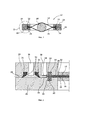
Фиг. 1: разрез через пленочную камеру, иFIG. 1: section through a film chamber, and
Фиг. 2: деталь в соответствии с II на фиг. 1.FIG. 2: detail in accordance with II in FIG. one.
Пленочная камера 12 имеет два пленочных слоя 14, 16, которые в своей краевой области приложены друг к другу и в своей середине охватывают испытуемый объект. Каждый пленочный слой 14, 16 в своей краевой области имеет окружной удерживающий профиль 20, который цельно приформован к соответствующему пленочному слою 14, 16. Удерживающий профиль 20 пленочного слоя 14 введен в удерживающий паз 22 первого рамочного элемента 24. Удерживающий профиль 20 нижнего пленочного слоя 16 введен в удерживающий паз 22 второго рамочного элемента 26. Удерживающие пазы 22 в каждом случае образованы в поверхности соответствующего рамочного элемента 24, 26. В случае с удерживающими пазами 22 речь идет об круговых углублениях, форма которых комплементарна форме соответствующего удерживающего профиля 20. При этом каждый удерживающий профиль 20 выполнен как круговой выступ в краевой области пленочного слоя. Каждый пленочный слой 14, 16, прежде всего, может также иметь несколько удерживающих профилей с различными круговыми профилями, которые входят в зацепление с соответствующими несколькими удерживающими пазами с различными круговыми профилями в соответствующем рамочном элементе.The
Рамочные элементы 24, 26 приложены друг к другу своими зажимными поверхностями 28, причем между зажимными поверхностями 28 удерживается уплотнение 30, чтобы создать газонепроницаемое соединение для герметично закрытой пленочной камеры 12. Уплотнение 30 образовано двумя удаленными друг от друга уплотнительными манжетами, которые в каждом случае удерживаются в уплотнительном пазе 31 одного рамочного элемента 24 и прижимаются к зажимной поверхности 28 другого удерживающего элемента 26.The
Между обеими уплотнительными манжетами уплотнения 30 в одном из обоих рамочных элементов 24 образован втяжной вентиляционный канал 36, через который промежуточное пространство между обеими уплотнительными манжетами и примыкающими зажимными поверхностями может быть вакуумировано. Кроме того, между уплотнением 30 и удерживающими профилями 20 пленочных слоев 14, 16 предусмотрен вытяжной вентиляционный канал 38 в одном из обоих рамочных элементов 24. Через вытяжной вентиляционный канал 38 вакуумируется промежуточное пространство между обоими пленочными слоями 14, 16 и тем самым пленочная камера 12.Between the two sealing lips of the
Каждый удерживающий паз 22 покрывается газопроводящим элементом 32, для предотвращения соответствующего удерживающего профиля 20 от выскальзывания из удерживающего паза 22. При этом каждый газопроводящий элемент 32 зафиксирован на соответствующей зажимной поверхности 28 застежкой 34.Each
Изобретение дает то преимущество, что пленочные слои 14, 16 не должны зажиматься в обоих рамочных элементах 24, 26 посредством давления на поверхность, чтобы создать стабильное соединение, которое является достаточным для нагрузки на растяжение. Рамочные элементы должны прижиматься друг к другу лишь с такой силой, чтобы создавалось газонепроницаемое соединение. При этом зацепление удерживающего профиля 20 и удерживающего паза 22 образует газонепроницаемую посадку с геометрическим замыканием, которая делает возможной достаточную растягивающую нагрузку соответствующих пленочных слоев 14, 16.The invention provides the advantage that the
Claims (9)
Applications Claiming Priority (3)
| Application Number | Priority Date | Filing Date | Title |
|---|---|---|---|
| DE102014219473.3A DE102014219473A1 (en) | 2014-09-25 | 2014-09-25 | Foil chamber with holding profile |
| DE102014219473.3 | 2014-09-25 | ||
| PCT/EP2015/071180 WO2016046039A1 (en) | 2014-09-25 | 2015-09-16 | Film chamber with retaining profile |
Publications (3)
| Publication Number | Publication Date |
|---|---|
| RU2017114155A RU2017114155A (en) | 2018-10-25 |
| RU2017114155A3 RU2017114155A3 (en) | 2019-02-01 |
| RU2701878C2 true RU2701878C2 (en) | 2019-10-02 |
Family
ID=54150393
Family Applications (1)
| Application Number | Title | Priority Date | Filing Date |
|---|---|---|---|
| RU2017114155A RU2701878C2 (en) | 2014-09-25 | 2015-09-16 | Film camera with holding profile |
Country Status (9)
| Country | Link |
|---|---|
| US (1) | US10401251B2 (en) |
| EP (1) | EP3198254B1 (en) |
| JP (1) | JP6602854B2 (en) |
| CN (1) | CN106716099B (en) |
| AU (1) | AU2015321046B2 (en) |
| BR (1) | BR112017005405B1 (en) |
| DE (1) | DE102014219473A1 (en) |
| RU (1) | RU2701878C2 (en) |
| WO (1) | WO2016046039A1 (en) |
Families Citing this family (2)
| Publication number | Priority date | Publication date | Assignee | Title |
|---|---|---|---|---|
| DE102017201004A1 (en) * | 2017-01-23 | 2018-07-26 | Inficon Gmbh | Foil chamber with double foil |
| US10914652B2 (en) * | 2018-05-31 | 2021-02-09 | Wcr, Inc. | Leak detection for heat exchanger plate |
Citations (3)
| Publication number | Priority date | Publication date | Assignee | Title |
|---|---|---|---|---|
| US5513516A (en) * | 1992-05-01 | 1996-05-07 | Visi-Pack, Inc. | Method and apparatus for leak testing a container |
| DE19935293A1 (en) * | 1999-07-27 | 2001-02-01 | Leybold Vakuum Gmbh | Foil leak detection chamber |
| DE102012200063A1 (en) * | 2012-01-03 | 2013-07-04 | Inficon Gmbh | Procedure for leak detection on a non-rigid specimen |
Family Cites Families (13)
| Publication number | Priority date | Publication date | Assignee | Title |
|---|---|---|---|---|
| US3792606A (en) * | 1972-04-17 | 1974-02-19 | American Can Co | Method and apparatus for enhancing detection of small leaks in articles |
| US3813923A (en) * | 1972-05-23 | 1974-06-04 | Universal Sales Eng Inc | Adaptive fixture for leak testing of containers |
| GB1484396A (en) * | 1974-02-22 | 1977-09-01 | Toyo Aluminium Kk | Apparatus for detecting leakage from container and method therefore |
| US5285678A (en) * | 1986-12-04 | 1994-02-15 | Seal Integrity Systems, Inc. | Container seal testing and pressurization |
| IT1273394B (en) * | 1994-03-31 | 1997-07-08 | Tetra Brik Res Dev Spa | DEVICE FOR DETECTION OF A LEAK |
| JPH09222144A (en) | 1996-02-16 | 1997-08-26 | Nippon Seiko Kk | Viscous damper |
| JP3688083B2 (en) | 1996-12-26 | 2005-08-24 | 東洋自動機株式会社 | Seal inspection method and apparatus |
| US5875918A (en) | 1997-02-20 | 1999-03-02 | Charles Chang | Hermetically-sealed container and closure construction |
| DE19846800A1 (en) | 1998-10-10 | 2000-04-13 | Leybold Vakuum Gmbh | Film leakage detector comprises two film sections which are tensioned in a frame, where each consists of two plastic sections |
| KR20030020364A (en) | 2001-05-22 | 2003-03-08 | 소니 가부시끼 가이샤 | Objective lens for optical pick up, optical pick up and disk drive device |
| US7565828B2 (en) * | 2005-06-10 | 2009-07-28 | Donbar Industries, Inc. | Systems and methods for testing packaging |
| DE102010015237B4 (en) * | 2010-04-15 | 2018-04-19 | Mondi Ag | Packaging container with a reclosure and method for producing a packaging container |
| DE102011086486B4 (en) * | 2011-11-16 | 2023-01-19 | Inficon Gmbh | Device and method for rapid leak detection on dimensionally stable/slack packaging without the addition of tracer gas |
-
2014
- 2014-09-25 DE DE102014219473.3A patent/DE102014219473A1/en not_active Withdrawn
-
2015
- 2015-09-16 JP JP2017515217A patent/JP6602854B2/en active Active
- 2015-09-16 AU AU2015321046A patent/AU2015321046B2/en active Active
- 2015-09-16 WO PCT/EP2015/071180 patent/WO2016046039A1/en active Application Filing
- 2015-09-16 EP EP15766786.6A patent/EP3198254B1/en active Active
- 2015-09-16 US US15/511,907 patent/US10401251B2/en active Active
- 2015-09-16 CN CN201580046400.9A patent/CN106716099B/en active Active
- 2015-09-16 RU RU2017114155A patent/RU2701878C2/en active
- 2015-09-16 BR BR112017005405-1A patent/BR112017005405B1/en active IP Right Grant
Patent Citations (3)
| Publication number | Priority date | Publication date | Assignee | Title |
|---|---|---|---|---|
| US5513516A (en) * | 1992-05-01 | 1996-05-07 | Visi-Pack, Inc. | Method and apparatus for leak testing a container |
| DE19935293A1 (en) * | 1999-07-27 | 2001-02-01 | Leybold Vakuum Gmbh | Foil leak detection chamber |
| DE102012200063A1 (en) * | 2012-01-03 | 2013-07-04 | Inficon Gmbh | Procedure for leak detection on a non-rigid specimen |
Also Published As
| Publication number | Publication date |
|---|---|
| BR112017005405B1 (en) | 2022-06-14 |
| BR112017005405A2 (en) | 2017-12-12 |
| AU2015321046B2 (en) | 2020-12-24 |
| CN106716099A (en) | 2017-05-24 |
| RU2017114155A (en) | 2018-10-25 |
| JP2017529534A (en) | 2017-10-05 |
| DE102014219473A1 (en) | 2016-03-31 |
| US10401251B2 (en) | 2019-09-03 |
| AU2015321046A1 (en) | 2017-03-23 |
| RU2017114155A3 (en) | 2019-02-01 |
| EP3198254B1 (en) | 2018-11-07 |
| EP3198254A1 (en) | 2017-08-02 |
| US20170292891A1 (en) | 2017-10-12 |
| CN106716099B (en) | 2019-12-24 |
| WO2016046039A1 (en) | 2016-03-31 |
| JP6602854B2 (en) | 2019-11-06 |
Similar Documents
| Publication | Publication Date | Title |
|---|---|---|
| RU2699927C2 (en) | Film chamber with measuring volume for large leak detection | |
| WO2015101835A3 (en) | Gasket | |
| RU2701878C2 (en) | Film camera with holding profile | |
| RU2017100540A (en) | MEASURING PRESSURE DIFFERENCE WITH THE FILM CAMERA | |
| BRPI0515834A (en) | double limb suction gasket | |
| WO2015028338A3 (en) | Tightness test during the evacuation of a film chamber | |
| EP2960082A3 (en) | Tire inflation system having a seal | |
| MY189771A (en) | Seal with lip projections | |
| SG10202003312TA (en) | Refrigerant leak sensor pre-trip sequence and diagnostics | |
| EA201792577A1 (en) | MULTILAYER GLAZING INCLUDING A PROFILED STRIP FOR CLAMP FASTENING WITH AN ADDITIONAL POLYMERIC BAND AND PROFILE STRIPED | |
| EP3637554A4 (en) | Seal cover, upper cover assembly and compressor | |
| US11248984B2 (en) | Method for leak testing and reference leak device for leak testing | |
| ZA202203104B (en) | Lightweight sealing gasket for low pressure and non-pressure applications | |
| SG11202111240TA (en) | Device for monitoring the tightness of sealing components | |
| SE545980C2 (en) | Sealing arrangement, method of monitoring leak tightness, and leak tightness monitoring system | |
| KR20160034542A (en) | Centering vacuum pipe | |
| US20150330429A1 (en) | Panel assembly strip by clamping on a supporting frame | |
| KR102287932B9 (en) | Seal with gas leak detection function high pressure gas container and gas leak monitoring system equipped with the same | |
| KR101807757B1 (en) | Vaccum Pipping Device For Seal | |
| WO2020260572A9 (en) | Method for testing the seal of a sealed membrane | |
| JP2017529534A5 (en) | ||
| RU2012127756A (en) | INSTALLATION FOR EXTERNAL INFLUENCE TESTS AND METHOD OF ITS USE (OPTIONS) | |
| EP3805616A4 (en) | Seal ring and sealing structure | |
| CA3022072C (en) | Sealing device and method of installation | |
| JP2016063656A (en) | Gas leakage repair tool and gas leakage repair method for communication cable closure |