RU2698503C1 - Method for making liquid circuit of spacecraft temperature control system - Google Patents
Method for making liquid circuit of spacecraft temperature control system Download PDFInfo
- Publication number
- RU2698503C1 RU2698503C1 RU2018119397A RU2018119397A RU2698503C1 RU 2698503 C1 RU2698503 C1 RU 2698503C1 RU 2018119397 A RU2018119397 A RU 2018119397A RU 2018119397 A RU2018119397 A RU 2018119397A RU 2698503 C1 RU2698503 C1 RU 2698503C1
- Authority
- RU
- Russia
- Prior art keywords
- liquid circuit
- filling
- liquid
- coolant
- hydraulic
- Prior art date
Links
- 239000007788 liquid Substances 0.000 title claims abstract description 40
- 238000000034 method Methods 0.000 title description 9
- 238000004519 manufacturing process Methods 0.000 claims abstract description 15
- 239000002904 solvent Substances 0.000 claims abstract description 14
- 238000005086 pumping Methods 0.000 claims abstract description 4
- 239000002826 coolant Substances 0.000 claims description 30
- 238000011010 flushing procedure Methods 0.000 claims description 2
- 230000008014 freezing Effects 0.000 claims 1
- 238000007710 freezing Methods 0.000 claims 1
- 239000012530 fluid Substances 0.000 abstract description 2
- 238000005406 washing Methods 0.000 abstract description 2
- 239000000126 substance Substances 0.000 abstract 1
- 238000010586 diagram Methods 0.000 description 2
- 239000002828 fuel tank Substances 0.000 description 2
- NHTMVDHEPJAVLT-UHFFFAOYSA-N Isooctane Chemical compound CC(C)CC(C)(C)C NHTMVDHEPJAVLT-UHFFFAOYSA-N 0.000 description 1
- 239000012080 ambient air Substances 0.000 description 1
- 238000004458 analytical method Methods 0.000 description 1
- JVSWJIKNEAIKJW-UHFFFAOYSA-N dimethyl-hexane Natural products CCCCCC(C)C JVSWJIKNEAIKJW-UHFFFAOYSA-N 0.000 description 1
- 230000008034 disappearance Effects 0.000 description 1
- 238000005516 engineering process Methods 0.000 description 1
- 239000000446 fuel Substances 0.000 description 1
- 230000001771 impaired effect Effects 0.000 description 1
- 239000004973 liquid crystal related substance Substances 0.000 description 1
- 230000003278 mimic effect Effects 0.000 description 1
Images
Classifications
-
- B—PERFORMING OPERATIONS; TRANSPORTING
- B64—AIRCRAFT; AVIATION; COSMONAUTICS
- B64G—COSMONAUTICS; VEHICLES OR EQUIPMENT THEREFOR
- B64G1/00—Cosmonautic vehicles
- B64G1/22—Parts of, or equipment specially adapted for fitting in or to, cosmonautic vehicles
- B64G1/46—Arrangements or adaptations of devices for control of environment or living conditions
- B64G1/50—Arrangements or adaptations of devices for control of environment or living conditions for temperature control
-
- G—PHYSICS
- G01—MEASURING; TESTING
- G01M—TESTING STATIC OR DYNAMIC BALANCE OF MACHINES OR STRUCTURES; TESTING OF STRUCTURES OR APPARATUS, NOT OTHERWISE PROVIDED FOR
- G01M3/00—Investigating fluid-tightness of structures
- G01M3/02—Investigating fluid-tightness of structures by using fluid or vacuum
Landscapes
- Engineering & Computer Science (AREA)
- Toxicology (AREA)
- Biodiversity & Conservation Biology (AREA)
- Environmental & Geological Engineering (AREA)
- Environmental Sciences (AREA)
- General Health & Medical Sciences (AREA)
- Health & Medical Sciences (AREA)
- Life Sciences & Earth Sciences (AREA)
- Remote Sensing (AREA)
- Aviation & Aerospace Engineering (AREA)
- Physics & Mathematics (AREA)
- General Physics & Mathematics (AREA)
- Liquid Crystal (AREA)
Abstract
Description
Изобретение относится к космической технике, в частности к способам изготовления жидкостных контуров (ЖК) систем терморегулирования (СТР) космических аппаратов (КА).The invention relates to space technology, in particular to methods for manufacturing liquid circuits (LC) of thermal control systems (CTP) of spacecraft (SC).
СТР КА, например, соответствующий патенту №2191359 [1] изготавливают с использованием патента Российской Федерации №2392200 [2], взятого в качестве прототипа. При изготовлении ЖК СТР КА производят гидравлическое соединение ЖК с «Выходом и «Входом» устройства заправки двумя соединительными трубопроводами с гидравлическими разъемами на концах, заполнение и промывку ЖК чистым деаэрированным растворителем перед проверкой герметичности ЖК, затем заполнение его и прокачку деаэрированного теплоносителя с помощью указанного устройства, имеющего в своем составе пневмоклапаны, функционирующие по командам с персонального компьютера, а так же датчики давления и температуры. Данные признаки прототипа являются общими с изобретением.STR KA, for example, corresponding to the patent No. 2191359 [1] is manufactured using the patent of the Russian Federation No. 2392200 [2], taken as a prototype. In the manufacture of LCD STR-KA, the LCD is hydraulically connected to the “Output and Input” of the filling device with two connecting pipelines with hydraulic connectors at the ends, filling and washing the LCD with clean deaerated solvent before checking the liquid tightness, then filling it and pumping the deaerated coolant using the specified device , which includes pneumatic valves that operate on commands from a personal computer, as well as pressure and temperature sensors. These features of the prototype are common with the invention.
Для обеспечения дистанционного управления работой устройство заправки снабжено пневмоклапанами и операторы по мнемосхеме устройства заправки, выполненной на персональном компьютере, осуществляют заправку ЖК СТР, выполняя требуемые команды технологического процесса заправки. В результате такого выполнения заправки ЖК СТР исключаются ошибки человеческого фактора в процессе заправки ЖК СТР КА.To provide remote control of the operation, the refueling device is equipped with pneumatic valves, and the operators, by the mimic diagram of the refueling device made on a personal computer, refuel the LCD CTP, following the required commands of the refueling technological process. As a result of such a performance of refueling the LCD STR, the errors of the human factor in the process of refueling the LCD STR are eliminated.
Однако, опыт заправки ЖК СТР устройством заправки показал, что возможно возникновение аварийного режима для ЖК СТР КА, когда персональный компьютер зависает или случилось аварийное пропадание электрического питания компьютера - в этом случае возможно:However, the experience of refueling the LCD STR with a refueling device showed that it is possible that an emergency mode can occur for the LCD STR of the KA, when the personal computer freezes or an emergency loss of the computer’s power supply occurs - in this case, it is possible:
1) неконтролируемое повышение давления над зеркалом теплоносителя (или растворителя) и, следовательно, повышение давления в ЖК СТР выше допустимого из-за нерабочего положения рабочих органов пневмоклапанов;1) an uncontrolled increase in pressure over the mirror of the coolant (or solvent) and, therefore, the increase in pressure in the LCD STR is higher than permissible due to the inoperative position of the working bodies of the pneumatic valves;
2) пропадание гидравлического сообщения ЖК СТР с полостью заправочного бака (например, функционально пневмоклапан на выходе из заправочного бака выполнен по схеме «Нормально закрыт» в обесточенном состоянии - что обеспечивает сохранение заблаговременно деаэрированного теплоносителя в баке до начала заправки) и, следовательно, в случае повышения температуры окружающего воздуха происходит недопустимое повышение давления в ЖК СТР и возможна разгерметизация его, что означает потерю работоспособности СТР.2) the disappearance of the hydraulic message of the LCD STR with the cavity of the fuel tank (for example, the pneumatic valve at the outlet of the fuel tank is functionally made according to the “Normally Closed” circuit in a de-energized state - which ensures that the deaerated coolant is kept in the tank in advance until the fuel starts) and, therefore, in the case of An increase in the ambient temperature leads to an unacceptable increase in pressure in the liquid crystal housing and its depressurization is possible, which means the loss of operability of the mechanical heater.
Таким образом, существенным недостатком известного способа изготовления ЖК СТР КА является недостаточно высокая надежность обеспечения работоспособности изготавливаемого ЖК СТР на этапе проведения заправки его теплоносителем (растворителем).Thus, a significant drawback of the known method for manufacturing LC STR is the insufficiently high reliability of ensuring the operability of the manufactured LCD STR at the stage of refueling it with a coolant (solvent).
Целью предлагаемого изобретения является устранение вышеуказанного существенного недостатка.The aim of the invention is to eliminate the above significant drawback.
Поставленная цель достигается тем, что в способе изготовления жидкостного контура системы терморегулирования космического аппарата, включающем гидравлическое соединение жидкостного контура с «Выходом» и «Входом» устройства заправки двумя соединительными трубопроводами с гидравлическими разъемами на концах, заполнение и промывку жидкостного контура чистым деаэрированным растворителем перед проверкой герметичности жидкостного контура, затем заполнение его и прокачку деаэрированного теплоносителя с помощью указанного устройства, имеющего в своем составе соединенные трубопроводами гидронасос, клапаны, например, пневмоклапаны, функционирующие по командам с персонального компьютера, а также датчики давления и температуры, при этом:This goal is achieved by the fact that in the method of manufacturing the liquid circuit of the spacecraft thermal control system, comprising hydraulically connecting the liquid circuit to the “Output” and “Input” of the filling device with two connecting pipelines with hydraulic connectors at the ends, filling and flushing the liquid circuit with a clean deaerated solvent before checking tightness of the liquid circuit, then filling it and pumping the deaerated coolant using the specified device , which includes a hydraulic pump connected by pipelines, valves, for example, pneumatic valves, operating on commands from a personal computer, as well as pressure and temperature sensors, while:
- на участке одного из соединительных трубопроводов вблизи его гидравлического разъема, присоединенного к соединительному трубопроводу, идущему по направлению к жидкостному контуру, устанавливают компенсационное устройство, например, компенсатор объема, жидкостную и газовую полости которого предварительно заправляют требуемыми количествами деаэрированного теплоносителя и газа, причем жидкостная полость его содержит присоединенный к ней трубопровод с гидравлическим разъемом на его свободном конце, который стыкуют с гидравлическим разъемом соединительного трубопровода после немедленной отстыковки гидравлических разъемов соединительных трубопроводов от «Входа» и «Выхода» устройства заправки при произвольном обесточивании или зависании персонального компьютера на время, установленное в технических условиях на жидкостный контур, например, до 10 минут, или после начала неуправляемого изменения (понижения или повышения) давления теплоносителя на выходе устройства заправки в сторону недопустимых давлений;- in the area of one of the connecting pipelines near its hydraulic connector connected to the connecting pipe going towards the liquid circuit, a compensation device is installed, for example, a volume compensator, the liquid and gas cavities of which are pre-charged with the required quantities of deaerated coolant and gas, and the liquid cavity it contains a pipeline connected to it with a hydraulic connector at its free end, which is joined with a hydraulic a connecting pipe connector after immediately disconnecting the hydraulic connectors of the connecting pipes from the “Input” and “Output” of the refueling device when the personal computer is de-energized or freezes for a period set in the technical specifications for the liquid circuit, for example, up to 10 minutes, or after the start of an uncontrolled change ( lowering or increasing) the coolant pressure at the outlet of the refueling device in the direction of unacceptable pressures;
- после начала неуправляемого изменения давления теплоносителя на выходе устройства в сторону недопустимых давлений перед отстыковкой гидравлических разъемов соединительных трубопроводов от устройства заправки отсекают линии подачи сжатого газа и вакуумирования;- after the start of an uncontrolled change in the pressure of the coolant at the outlet of the device in the direction of unacceptable pressures, the compressed gas and vacuum lines are cut off from the filling device before undocking the hydraulic connectors of the connecting pipelines;
- после заполнения жидкостного контура растворителем или теплоносителем любую последовательность команд с персонального компьютера выполняют после контроля соответствия: полость заправочного бака гидравлически сообщена с жидкостным контуром, что и является, по мнению авторов, существенными отличительными признаками предложенного авторами технического решения.- after filling the liquid circuit with solvent or coolant, any sequence of commands from the personal computer is performed after conformity control: the cavity of the refueling tank is hydraulically connected to the liquid circuit, which, according to the authors, is the essential distinguishing feature of the technical solution proposed by the authors.
В результате проведенного авторами анализа известной патентной и научно-технической литературы, предложенное сочетание существенных признаков заявляемого технического решения в известных источниках не обнаружено и, следовательно, известные технические решения не проявляют тех же свойств, что в заявленном способе изготовления жидкостного контура системы терморегулирования космического аппарата.As a result of the analysis of the known patent and scientific and technical literature by the authors, the proposed combination of the essential features of the claimed technical solution was not found in the known sources and, therefore, the known technical solutions do not exhibit the same properties as in the claimed method for manufacturing the liquid circuit of the spacecraft thermal control system.
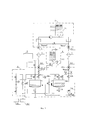
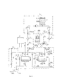
Суть изобретения поясняется чертежами. На фиг. 1 и 2 изображены принципиальные схемы реализации предлагаемого технического решения, где поз. 1 - жидкостный контур (ЖК) СТР в составе КА; (ЖК 1 включает в себя: компенсатор объема 1.1, герметичная газовая полость 1.1.1 которого заправлена двухфазным рабочим телом - фреоном 141 в, давление паров которого в условиях изготовления изменяется в диапазоне 0,65-0,85 кгс/см2 (соответствует температуре окружающего воздуха в цехе (24±3)°С), а разделенная от нее сильфоном жидкостная полость 1.1.2 в процессе заправки заполнена деаэрированным теплоносителем, например, ЛЗ-ТК-2, и гидравлически сообщена с полностью заполненным остальным жидкостным контуром); 2 - персональный компьютер; 3 и 5 - соединительные трубопроводы с гидравлическими разъемами 3.1, 3.2, 5.1, 5.2 на их концах; 4 - компенсатор объема (в комплекте с соединительным трубопроводом с гидравлическим разъемом, например, 4.1); 6 - пневмовакуумный ввод (6.1 - источник сжатого газа; 6.2 - вакуумный насос); 7 - устройство заправки (7.1 - датчик температуры; 7.2 - датчик абсолютного давления; 7.3, 7.4 - пневмоклапаны (в исходном положении «Нормально открыт»); 7.5 - заправочный бак; 7.6 - пневмоклапан (в исходном положении «Нормально закрыт»); 7.7 - жидкостный тракт устройства заправки; 7.8 - гидронасос устройства заправки).The essence of the invention is illustrated by drawings. In FIG. 1 and 2 are schematic diagrams of the implementation of the proposed technical solution, where pos. 1 - liquid circuit (LC) STR in the spacecraft; (
Предложенный способ изготовления жидкостного контура системы терморегулирования космического аппарата включает в себя нижеуказанные операции, выполняемые в следующей последовательности (см. фиг. 1 и 2):The proposed method for manufacturing the liquid circuit of the spacecraft thermal control system includes the following operations performed in the following sequence (see Fig. 1 and 2):
1. Изготавливают КА, в том числе ЖК 1 СТР (к моменту изготовления КА соединительные трубопроводы 3 и 5, компенсатор объема 4, пневмовакуумный ввод 6 и устройство заправки 7 изготовлены).1. They make spacecraft, including ZhK 1 STR (at the time of production of the spacecraft, connecting
2. Устанавливают КА (в т.ч. ЖК 1 СТР), соединительные трубопроводы 3 и 5, компенсатор объема 4, пневмовакуумный ввод 6, устройство заправки 7, в помещении для заправки на отведенных для них рабочих местах и собирают схему заправки, соответствующую схеме, приведенной на фиг. 1; данную схему собирают два раза: перед заправкой чистым деаэрированным растворителем и перед заправкой деаэрированным теплоносителем.2. Install spacecraft (including ZhK 1 STR), connecting
3. Заблаговременно проводят деаэрацию чистого растворителя (теплоносителя) в заправочном баке 7.5 - при этом пневмоклапан 7.6 «Нормально закрыт».3. Deaeration of a pure solvent (coolant) in a refueling tank 7.5 is carried out in advance - in this case, the pneumatic valve 7.6 "Normally Closed".
4. Вакуумируют жидкостные тракты ЖК 1 СТР, соедительных трубопроводов 3, 5 и жидкостный тракт 7.7 устройства заправки 7.4. Vacuum the liquid paths of the
5. Под абсолютным давлением 1,4-1,5 кгс/см2 (согласно требованию инструкции на заправку ЖК СТР) над зеркалом растворителя (теплоносителя) в заправочном баке 7.5 осуществляют открытие пневмоклапана 7.6 и происходит полное заполнение жидкостных трактов ЖК 1 СТР, соединительных трубопроводов 3 и 5 и соответствующих жидкостных трактов устройства заправки 7.5. Under an absolute pressure of 1.4-1.5 kgf / cm 2 (according to the requirements of the instructions for refilling the LCD STR) above the solvent (coolant) mirror in the refueling tank 7.5, the pneumatic valve 7.6 is opened and the liquid paths of the
6. Выдерживают заполоненные полностью жидкостные тракты по п. 5 под абсолютным давлением 1,4 - 1,5 кгс/см не менее 30 минут (согласно требованию инструкции на заправку ЖК СТР).6. Withstand filled completely liquid paths according to
7. В процессе заправки:7. During refueling:
- непрерывно контролируют температуру (поз. 7.1), которая должна быть в пределах (24±3)°С, и величину абсолютного давления теплоносителя (поз. 7.2) на выходе из устройства заправки 7, которое должно поддерживаться в диапазоне 1,4-1,5 кгс/см2 (максимально допустимое абсолютное давление в ЖК 1 СТР согласно техническим условиям - не более 2 кгс/см);- continuously monitor the temperature (pos. 7.1), which should be within (24 ± 3) ° С, and the absolute value of the coolant pressure (pos. 7.2) at the outlet of the
- непрерывно контролируют положение пнемоклапанов 7.4 и 7.6: пневмоклапаны 7.4 и 7.6 должны быть открыты;- continuously monitor the position of the pneumatic valves 7.4 and 7.6: pneumatic valves 7.4 and 7.6 must be open;
- любую последовательность команд с персонального компьютера выполняют после контроля соответствия: полость заправочного бака 7.5 гидравлически сообщена с ЖК 1 СТР.- any sequence of commands from a personal computer is performed after conformity control: the cavity of the filling tank 7.5 is hydraulically connected to the
8. Если замечания по предыдущим операциям не зафиксированы, значит ЖК 1 СТР деаэрированным растворителем (теплоносителем) заполнен качественно и сливают согласно инструкции на заправку из ЖК 1 СТР необходимую дозу теплоносителя (в случае заправки СТР теплоносителем) для обеспечении компенсации температурного изменения объема теплоносителя, заправленного в ЖК 1, при дальнейшей эксплуатации КА.8. If comments on previous operations are not recorded, then
9. Если же в процессе выполнения операций п.п. 5-7, например, произошло зависание персонального компьютера 2 или пропало напряжение питания устройства заправки 7 и персонального компьютера 2, то это означает, например, что происходит закрытие пневмоклапана 7.6 и ЖК 1 СТР остается без обеспечения компенсации температурного изменения объема теплоносителя, т.к. его жидкостный тракт полностью заправлен теплоносителем (сильфон его компенсатора объема полностью сжат), и в этом случае, согласно опытным данным (предусмотренным в технических условиях), время пребывания ЖК 1 СТР без компенсации температурного изменения объема теплоносителя должно быть не более 10 минут.9. If, in the process of performing operations, paragraphs. 5-7, for example, the
10. Если в течение 10 минут не обеспечивалось открытие пневмоклапана 7.6, то (см. фиг. 2) немедленно отстыковывают гидравлические разъемы 3.2 и 5.2 и затем к разъему гидравлическому 5.2 (или 3.2) пристыковывают разъем гидравлический 4.1 компенсатора объема 4 (который предварительно заправлен требуемым количеством теплоносителя и газа: жидкостная полость - теплоносителем, а газовая полость - газом).10. If within 10 minutes the pneumatic valve 7.6 was not opened, then (see Fig. 2) immediately disconnect the hydraulic connectors 3.2 and 5.2 and then connect the hydraulic connector 4.1 of the volume compensator 4 (which is pre-charged with the required one) to the hydraulic connector 5.2 (or 3.2) the amount of coolant and gas: the liquid cavity is the coolant, and the gas cavity is gas).
Выполнение этой операции гарантирует, что ЖК 1 СТР в процессе заправки не пребывал под недопустимым давлением и качество изготовление ЖК 1 СТР не нарушилось.Performing this operation ensures that the
11. Устраняют причину отказа устройства заправки 7, после чего отстыковывают компенсатор объема 4 от соединительного трубопровода 5.2, затем соединительные трубопроводы 3 и 5 пристыковывают к «Выходу» и «Входу» устройства заправки 7 и продолжают заправку ЖК 1 чистым растворителем (изооктаном) или теплоносителем (ЛЗ-ТК-2).11. Eliminate the reason for the refueling
Таким образом, как видно из вышеуказанного, в результате использования при изготовлении КА предложенного авторами способа изготовления СТР на этапах заполнения ее ЖК 1 чистым растворителем или теплоносителем гарантированно обеспечивается высокая надежность работоспособности ЖК 1 СТР КА, т.е. тем самым достигается цель изобретения.Thus, as can be seen from the above, as a result of using the method of manufacturing the STR proposed by the authors at the stages of filling its
Claims (3)
Priority Applications (1)
| Application Number | Priority Date | Filing Date | Title |
|---|---|---|---|
| RU2018119397A RU2698503C1 (en) | 2018-05-25 | 2018-05-25 | Method for making liquid circuit of spacecraft temperature control system |
Applications Claiming Priority (1)
| Application Number | Priority Date | Filing Date | Title |
|---|---|---|---|
| RU2018119397A RU2698503C1 (en) | 2018-05-25 | 2018-05-25 | Method for making liquid circuit of spacecraft temperature control system |
Publications (1)
| Publication Number | Publication Date |
|---|---|
| RU2698503C1 true RU2698503C1 (en) | 2019-08-28 |
Family
ID=67851338
Family Applications (1)
| Application Number | Title | Priority Date | Filing Date |
|---|---|---|---|
| RU2018119397A RU2698503C1 (en) | 2018-05-25 | 2018-05-25 | Method for making liquid circuit of spacecraft temperature control system |
Country Status (1)
| Country | Link |
|---|---|
| RU (1) | RU2698503C1 (en) |
Cited By (1)
| Publication number | Priority date | Publication date | Assignee | Title |
|---|---|---|---|---|
| RU210075U1 (en) * | 2021-08-03 | 2022-03-28 | Акционерное общество "Информационные спутниковые системы" имени академика М.Ф. Решетнёва" | REFUELING DEVICE OF SPACE VEHICLE THERMAL CONTROL SYSTEM |
Citations (4)
| Publication number | Priority date | Publication date | Assignee | Title |
|---|---|---|---|---|
| RU2238886C2 (en) * | 2002-03-11 | 2004-10-27 | Федеральное государственное унитарное предприятие "Научно-производственное объединение прикладной механики им. акад. М.Ф. Решетнева" | Method of manufacture of spacecraft |
| US20080184775A1 (en) * | 2006-01-30 | 2008-08-07 | Mitsui Mining & Smelting Co., Ltd. | Fluid Identification Device and Fluid Identification Method |
| US20130186182A1 (en) * | 2010-09-30 | 2013-07-25 | Toyota Jidosha Kabushiki Kaisha | Leak inspection device and leak inspection method |
| RU2574104C1 (en) * | 2014-07-03 | 2016-02-10 | Акционерное общество "Информационные спутниковые системы" имени академика М.Ф. Решетнёва" | Method of fabricating spacecraft thermal control system liquid circuit |
-
2018
- 2018-05-25 RU RU2018119397A patent/RU2698503C1/en active
Patent Citations (4)
| Publication number | Priority date | Publication date | Assignee | Title |
|---|---|---|---|---|
| RU2238886C2 (en) * | 2002-03-11 | 2004-10-27 | Федеральное государственное унитарное предприятие "Научно-производственное объединение прикладной механики им. акад. М.Ф. Решетнева" | Method of manufacture of spacecraft |
| US20080184775A1 (en) * | 2006-01-30 | 2008-08-07 | Mitsui Mining & Smelting Co., Ltd. | Fluid Identification Device and Fluid Identification Method |
| US20130186182A1 (en) * | 2010-09-30 | 2013-07-25 | Toyota Jidosha Kabushiki Kaisha | Leak inspection device and leak inspection method |
| RU2574104C1 (en) * | 2014-07-03 | 2016-02-10 | Акционерное общество "Информационные спутниковые системы" имени академика М.Ф. Решетнёва" | Method of fabricating spacecraft thermal control system liquid circuit |
Cited By (1)
| Publication number | Priority date | Publication date | Assignee | Title |
|---|---|---|---|---|
| RU210075U1 (en) * | 2021-08-03 | 2022-03-28 | Акционерное общество "Информационные спутниковые системы" имени академика М.Ф. Решетнёва" | REFUELING DEVICE OF SPACE VEHICLE THERMAL CONTROL SYSTEM |
Similar Documents
| Publication | Publication Date | Title |
|---|---|---|
| CN103234761B (en) | Low-thrust rocket nigration platform | |
| JP6517207B2 (en) | Method for performing an emergency shaft seal for a reactor coolant pump and shaft seal assembly | |
| CN101326396B (en) | Plug-in connections for cryogenic lines | |
| CN114927721A (en) | Device for supplying a fluid to a user facility | |
| CN110168275A (en) | Pressure Vessel Systems for Motor Vehicles | |
| CN118655941B (en) | Environmental load control system and method for deep geotechnical engineering disturbance simulation facility | |
| US20250334305A1 (en) | Apparatus and systems for separating phases in liquid hydrogen pumps | |
| CN204783616U (en) | Automatic trail pump chamber pressure variation's mechanical seal system | |
| RU2200689C2 (en) | Method of testing spacecraft and device for realization of this method | |
| CN219640041U (en) | Special gas supply high-pressure leak detection compensation equipment | |
| CN204646824U (en) | High integrated digital hydraulic control cabin | |
| RU2683811C1 (en) | Plant for recuperation and reuse of control gases during a leak test of products | |
| RU2191359C2 (en) | Spacecraft temperature control system and method of its manufacture | |
| RU2571701C2 (en) | Valves for fossil fuel production and transport with safety unit | |
| CN105865718A (en) | Sealing performance testing apparatus of sealing structure | |
| CN116971896A (en) | Low-temperature propellant supply system and pre-cooling method | |
| CN209604734U (en) | Quick connector and vacuum pump | |
| CN115654250A (en) | Corrugated pipe expansion joint type with pressurizing device and using method | |
| RU210075U1 (en) | REFUELING DEVICE OF SPACE VEHICLE THERMAL CONTROL SYSTEM | |
| RU2731136C1 (en) | Method for improving operating reliability of a sealed compartment equipment cooling system | |
| CN204785273U (en) | High compensation volume sleeve pipe compensator | |
| RU2698573C1 (en) | Test method of spacecraft temperature control system | |
| CN223740327U (en) | Pressure relief components and oil and gas extraction equipment | |
| CN201315168Y (en) | Structure for improving internal pressure of still pipe segment | |
| CN106402562A (en) | Air pressure type sleeve compensator |