RU2695257C2 - Method for operation of toothbrush with automatic detection of cleaning angle (embodiments) - Google Patents
Method for operation of toothbrush with automatic detection of cleaning angle (embodiments) Download PDFInfo
- Publication number
- RU2695257C2 RU2695257C2 RU2017115656A RU2017115656A RU2695257C2 RU 2695257 C2 RU2695257 C2 RU 2695257C2 RU 2017115656 A RU2017115656 A RU 2017115656A RU 2017115656 A RU2017115656 A RU 2017115656A RU 2695257 C2 RU2695257 C2 RU 2695257C2
- Authority
- RU
- Russia
- Prior art keywords
- toothbrush
- longitudinal axis
- angle
- cleaning
- bristles
- Prior art date
Links
Images
Classifications
-
- A—HUMAN NECESSITIES
- A61—MEDICAL OR VETERINARY SCIENCE; HYGIENE
- A61C—DENTISTRY; APPARATUS OR METHODS FOR ORAL OR DENTAL HYGIENE
- A61C17/00—Devices for cleaning, polishing, rinsing or drying teeth, teeth cavities or prostheses; Saliva removers; Dental appliances for receiving spittle
- A61C17/16—Power-driven cleaning or polishing devices
-
- A—HUMAN NECESSITIES
- A46—BRUSHWARE
- A46B—BRUSHES
- A46B15/00—Other brushes; Brushes with additional arrangements
- A46B15/0002—Arrangements for enhancing monitoring or controlling the brushing process
- A46B15/0038—Arrangements for enhancing monitoring or controlling the brushing process with signalling means
- A46B15/004—Arrangements for enhancing monitoring or controlling the brushing process with signalling means with an acoustic signalling means, e.g. noise
-
- A—HUMAN NECESSITIES
- A46—BRUSHWARE
- A46B—BRUSHES
- A46B15/00—Other brushes; Brushes with additional arrangements
- A46B15/0002—Arrangements for enhancing monitoring or controlling the brushing process
- A46B15/0038—Arrangements for enhancing monitoring or controlling the brushing process with signalling means
- A46B15/0044—Arrangements for enhancing monitoring or controlling the brushing process with signalling means with light signalling means
-
- A—HUMAN NECESSITIES
- A46—BRUSHWARE
- A46B—BRUSHES
- A46B15/00—Other brushes; Brushes with additional arrangements
- A46B15/0002—Arrangements for enhancing monitoring or controlling the brushing process
- A46B15/0038—Arrangements for enhancing monitoring or controlling the brushing process with signalling means
- A46B15/0046—Arrangements for enhancing monitoring or controlling the brushing process with signalling means with vibrating signalling means
-
- A—HUMAN NECESSITIES
- A46—BRUSHWARE
- A46B—BRUSHES
- A46B9/00—Arrangements of the bristles in the brush body
- A46B9/02—Position or arrangement of bristles in relation to surface of the brush body, e.g. inclined, in rows, in groups
- A46B9/04—Arranged like in or for toothbrushes
-
- A—HUMAN NECESSITIES
- A61—MEDICAL OR VETERINARY SCIENCE; HYGIENE
- A61C—DENTISTRY; APPARATUS OR METHODS FOR ORAL OR DENTAL HYGIENE
- A61C17/00—Devices for cleaning, polishing, rinsing or drying teeth, teeth cavities or prostheses; Saliva removers; Dental appliances for receiving spittle
- A61C17/16—Power-driven cleaning or polishing devices
- A61C17/22—Power-driven cleaning or polishing devices with brushes, cushions, cups, or the like
- A61C17/221—Control arrangements therefor
Abstract
Description
ПРЕДПОСЫЛКИ СОЗДАНИЯ ИЗОБРЕТЕНИЯBACKGROUND OF THE INVENTION
1. Область техники, к которой относится изобретение1. The technical field to which the invention relates.
Настоящее изобретение относится к зубным щеткам, и, в частности, к зубной щетке, например, электрической зубной щетке, выполненной с возможностью определения угла чистки и предоставления обратной связи пользователю на основании чистящей силы, определенной под множеством углов.The present invention relates to toothbrushes, and in particular to a toothbrush, such as an electric toothbrush, configured to determine a brushing angle and provide feedback to a user based on a brushing force determined from a plurality of angles.
2. Предшествующий уровень техники2. The prior art
В целом, электрические зубные щетки для очистки зубов, в том числе для удаления бляшки, хорошо известны. Обычно электрические зубные щетки основаны на наборе щетинок, прикрепленных к щетиночной установочной пластине, которая, в свою очередь, двигается посредством приводного механизма для чистки поверхностей зубов. Такие зубные щетки, которые основаны на отскребающем действии щетинок для фактической очистки, обычно требуют некоторого количества силы, которая должна быть приложена пользователем к зубам для учета различий в различных формах и межзубных промежутках, и для эффективной очистки зубов. In general, electric toothbrushes for cleaning teeth, including for plaque removal, are well known. Typically, electric toothbrushes are based on a set of bristles attached to a bristle mounting plate, which, in turn, moves by means of a drive mechanism for cleaning tooth surfaces. Such toothbrushes, which are based on the scraping action of the bristles for actual cleaning, usually require a certain amount of force that must be applied by the user to the teeth to account for differences in different shapes and interdental spaces, and for effective toothbrushing.
Правильное положение щетинок зубной щетки относительно зубов является определяющим для эффективного удаления бляшки. Для наилучшего удаления бляшки с зубов часто предпочтительно чистить так, чтобы щетинки располагались под углом, близким к перпендикуляру к зубам. Испытания показали, что пользователи обычно чистят зубы под углом, далеким от перпендикулярного. Углы до 70 градусов от перпендикулярного являются обычными, особенно при чистке обращенной внутрь поверхности зубов. При таких чрезмерных углах многие щетинки уже не находятся в контакте с зубами (или расположены под неэффективным углом), и чистка является чрезвычайно неэффективной. The correct position of the bristles of the toothbrush relative to the teeth is crucial for the effective removal of plaque. To best remove plaque from the teeth, it is often preferable to brush so that the bristles are at an angle close to the perpendicular to the teeth. Tests have shown that users usually brush their teeth at an angle far from perpendicular. Angles of up to 70 degrees perpendicular are common, especially when brushing the surface of the teeth facing inward. At such excessive angles, many bristles are no longer in contact with the teeth (or located at an ineffective angle), and brushing is extremely ineffective.
WO 02/15742 раскрывает трехточечную воспринимающую силу систему, которая включает в себя три расположенных на расстоянии друг от друга чувствительных элемента, которые изменяют сопротивление линейно или монотонно в пределах выбранного диапазона приложенной к нему силы.
US 6,536,068 раскрывает способ мониторинга техники чистки зубов.US 6,536,068 discloses a method for monitoring tooth brushing techniques.
СУЩНОСТЬ ИЗОБРЕТЕНИЯSUMMARY OF THE INVENTION
В одном варианте осуществления обеспечивается зубная щетка, которая включает в себя чистящую головку, первый датчик силы для измерения первой силы, приложенной чистящей головке под первым углом к зубу, и второй датчик силы для измерения второй силы, приложенной чистящей головкой под вторым углом к зубу, при этом второй угол отличается от первого угла, и блок обработки данных. Блок обработки данных выполнен с возможностью: (i) приема первой информации, указывающей первую силу, измеренную первым датчиком силы, (ii) приема второй информации, указывающей вторую силу, измеренную вторым датчиком силы, и (iii) определения информации, касающейся имеющегося в настоящий момент угла чистки чистящей головки, на основании первой информации и второй информации.In one embodiment, a toothbrush is provided that includes a cleaning head, a first force sensor for measuring a first force applied by the cleaning head at a first angle to the tooth, and a second force sensor for measuring a second force applied by the cleaning head at a second angle to the tooth, wherein the second angle is different from the first angle, and the data processing unit. The data processing unit is configured to: (i) receive first information indicating the first force measured by the first force sensor, (ii) receive second information indicating the second force measured by the second force sensor, and (iii) determine information regarding the present angle of cleaning angle of the cleaning head, based on the first information and the second information.
В другом варианте осуществления обеспечивается способ работы зубной щетки, имеющей чистящую головку. Способ включает в себя этапы, на которых создают первую информацию, указывающую первую силу, приложенную чистящей головкой к зубам под первым углом, и вторую информацию, указывающую вторую силу, приложенную к зубам чистящей головкой под вторым углом, при этом второй угол отличается от первого угла, определяют информацию, касающуюся имеющегося в настоящий момент угла чистки чистящей головки на основании первой информации и второй информации, и предоставляют воспринимаемую пользователем обратную связь на основании определенной информации, касающейся имеющегося в настоящий момент угла чистки.In another embodiment, a method for operating a toothbrush having a cleaning head is provided. The method includes the steps of creating the first information indicating the first force applied by the cleaning head to the teeth at a first angle, and the second information indicating the second force applied to the teeth by the cleaning head at the second angle, the second angle being different from the first angle , determine information regarding the currently available cleaning angle of the cleaning head based on the first information and second information, and provide user-perceived feedback based on certain information and regarding the currently available cleaning angle.
Эти и другие цели, признаки и характеристики настоящего изобретения, а также способы работы и функции связанных элементов конструкции и сочетание частей и экономические показатели производства станут более очевидны при рассмотрении нижеприведенного описания и приложенной формулы со ссылкой на сопроводительные чертежи, образующие часть настоящего описания, при этом подобные номера ссылочных позиций обозначают соответствующие части на различных чертежах. Однако следует ясно понимать, что чертежи приведены только с целью иллюстрации и описания, и не предназначены для ограничения изобретения.These and other objectives, features and characteristics of the present invention, as well as methods of operation and functions of related structural elements and combination of parts and economic indicators of production will become more apparent when considering the following description and the attached formula with reference to the accompanying drawings forming part of the present description, like reference numerals indicate corresponding parts in various figures. However, it should be clearly understood that the drawings are for purposes of illustration and description only and are not intended to limit the invention.
КРАТКОЕ ОПИСАНИЕ ЧЕРТЕЖЕЙBRIEF DESCRIPTION OF THE DRAWINGS
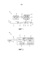
Фиг.1 - схематическое покомпонентное изображение зубной щетки согласно примерному варианту осуществления настоящего изобретения;Figure 1 is a schematic exploded view of a toothbrush according to an exemplary embodiment of the present invention;
Фиг.2 - принципиальная схема зубной щетки, изображенной на фиг.1;Figure 2 - schematic diagram of the toothbrush shown in figure 1;
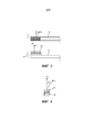
Фиг.3 и 4 - принципиальные схемы, иллюстрирующие два альтернативных частных варианты осуществления головки зубной щетки, представленной на фиг.1 и 2; и Figures 3 and 4 are schematic diagrams illustrating two alternative particular embodiments of the head of the toothbrush shown in Figures 1 and 2; and
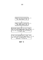
Фиг.5 - блок-схема, иллюстрирующая работу зубной щетки, представленной на фиг.1 и 2, согласно одному примерному варианту осуществления.FIG. 5 is a flowchart illustrating the operation of the toothbrush of FIGS. 1 and 2, according to one exemplary embodiment.
ПОДРОБНОЕ ОПИСАНИЕ ПРИМЕРНЫХ ВАРИАНТОВ ОСУЩЕСТВЛЕНИЯDETAILED DESCRIPTION OF EXAMPLE EMBODIMENTS
При использовании в настоящем документе единственное число включает в себя множественное, если только иное явно не следует из контекста. При использовании в настоящем документе утверждение, что две или более части или компонента “связаны” означает, что части соединены или работают вместе непосредственно или опосредовано, то есть посредством одной или более промежуточных частей или компонентов, при условии, что существует соединение. При использовании в настоящем документе “непосредственно соединенный” означает, что два элемента находятся в непосредственном контакте друг с другом. При использовании в настоящем документе “жестко соединенный” или “неподвижный” означает, что два компонента соединены так, чтобы двигаться как один, при этом сохраняя постоянную ориентацию друг относительно друга.When used in this document, the singular includes the plural, unless otherwise clearly follows from the context. As used herein, the statement that two or more parts or components are “connected” means that the parts are connected or work together directly or indirectly, that is, through one or more intermediate parts or components, provided that there is a connection. As used herein, “directly connected” means that the two elements are in direct contact with each other. As used herein, “rigidly connected” or “fixed” means that the two components are connected so as to move as one, while maintaining a constant orientation with respect to each other.
При использовании в настоящем документе слово “единый” означает компонент, созданный как единый элемент или блок. То есть компонент, который включает в себя элементы, созданные отдельно и затем соединенные вместе в виде блока, не является “единым” компонентом или телом. При использовании в настоящем документе утверждение, что две или более частей или компонентов “зацепляют” друг друга означает, что части прикладывают силу друг к другу или непосредственно или через одну или более промежуточных частей или компонентов. При использовании в настоящем документе термин “число” означает единицу или целое больше единицы (то есть множество).As used herein, the word “single” means a component created as a single element or block. That is, a component that includes elements created separately and then connected together in a block is not a “single” component or body. As used herein, the statement that two or more parts or components “hook” each other means that the parts apply force to each other either directly or through one or more intermediate parts or components. As used herein, the term “number” means a unit or an integer greater than one (ie, a plurality).
При использовании в настоящем документе термин “по существу перпендикулярно” означает - под углом 90 градусов ± 5 градусов.As used herein, the term “substantially perpendicular” means at an angle of 90 degrees ± 5 degrees.
При использовании в настоящем документе термин “по существу параллельно” означает - под углом 0 градусов ± 5 градусов.As used herein, the term “substantially parallel” means at an angle of 0 degrees ± 5 degrees.
Фразы, относящиеся к направлению, используемые в настоящем документе, например, и без ограничения, вверх, вниз, влево, вправо, верхний, нижний, передний, задний и их производные относятся к ориентации элементов, представленных на чертежах, и не должны ограничивать формулу, если иное специально не указано.Phrases related to the direction used in this document, for example, and without limitation, up, down, left, right, upper, lower, front, back and their derivatives relate to the orientation of the elements shown in the drawings, and should not limit the formula, unless otherwise expressly indicated.
Фиг.1 - схематическое покомпонентное изображение, а фиг.2 - принципиальная схема электрической зубной щетки 10 согласно примерному варианту осуществления настоящего изобретения. Как подробно описано в настоящем документе, зубная щетка 10 выполнена с возможностью обнаружения чистящей силы при множестве углов, которая, в отличие от зубных щеток предшествующего уровня техники, которые могут иметь единственный датчик силы, обеспечивает возможность получения угла чистящей головки, и, таким образом, угла чистки. Зубная щетка 10 включает в себя ручку 12 и двигатель 14 постоянного тока, который питается от аккумулятора 16. Двигатель 14 обеспечивает приведение в действие чистящей головки 18, которая, в свою очередь, съемно установлена на приводном вале 22 двигателя. Однако следует понимать, что в электрических зубных щетках могут использоваться различные альтернативные конструкции приводного действия, которые воплощают концепцию, раскрытую в настоящем документе. Иллюстрация двигателя постоянного тока в примерном варианте осуществления представляет собой только одну из нескольких возможных систем двигателя.Figure 1 is a schematic exploded view, and Figure 2 is a schematic diagram of an
Чистящая головка 18 включает в себя набор щетинок 24, установленных на щетиночной основе 25, которые совместно образуют щетиночный участок чистящей головки 18. Щетинки 24 выполняют очистку посредством колебательного действия, придаваемого чистящей головке 18 двигателем 14. Работа двигателя 14 управляется блоком 26 обработки данных, который представляет собой стандартный компонент электрических зубных щеток. Блок 26 обработки данных может представлять собой, например, и без ограничения, микропроцессор, микроконтроллер или любое другое подходящее устройство обработки, и может включать в себя подходящую память для хранения стандартных программ, выполняемых блоком 26 обработки данных.The
Как видно на фиг.1 и 2, в примерном варианте осуществления ручка 12 включает в себя первый датчик 30A силы для измерения чистящей силы, приложенной чистящей головкой 18 к зубам при использовании зубной щетки 10 под первым углом к продольной оси 32 зубной щетки 10 и продольной оси 36 щетинок 24 (как указано стрелкой на фиг.2), и второй датчик 30B силы для измерения чистящей силы, приложенной чистящей головкой 18 к зубам при использовании зубной щетки 10 под вторым углом к продольной оси 32 зубной щетки 10 и продольной оси 36 щетинок 24 (отличной от первой оси). В примерном варианте осуществления первый датчик 30A силы и второй датчик 30B силы расположены вблизи двигателя 14 и выполнены с возможностью измерения силы на приводном валу 22. Таким образом, первый датчик 30A силы и второй датчик 30B силы выполнены с возможностью и расположены так, чтобы измерять чистящие силы под двумя различными углами. Например, первый датчик 30A силы может быть выполнен с возможностью и расположен так, чтобы измерять чистящую силу под углом, по существу перпендикулярным продольной оси 32 зубной щетки 10 и по существу параллельным продольной оси 36 щетинок 24, а второй датчик 30B силы может быть выполнен с возможностью и расположен так, чтобы измерять чистящую силу под углом, по существу параллельным продольной оси 32 и по существу перпендикулярным продольной оси 36 щетинок 24. Однако следует принять во внимание, что эта конфигурация является только примерной, и что также возможны альтернативные углы для каждого датчика 30A и 30B силы в пределах объема концепции, раскрытой в настоящем документе. Множество примерных альтернативных конфигураций для датчиков 30A и 30B силы подробно описаны в других местах в настоящем документе. Кроме того, как видно на фиг.1 и 2, каждый - и первый датчик 30A силы, и второй датчик 30B силы - функционально соединен с блоком 26 обработки данных и предоставляет сигнал блоку 26 обработки данных, указывающий силы, измеренные таким образом. В альтернативном варианте осуществления датчики 30A и 30B силы могут располагаться в чистящей головке 18. Однако, как следует принять во внимание, первая конфигурация, в которой датчики 30A и 30B силы расположены в ручке 12, способствуют поддержанию низкой стоимости чистящей головки 18 и не допускают проблем с соединением между чистящей головкой 18 и ручкой 12.As can be seen in FIGS. 1 and 2, in an exemplary embodiment, the
Первый датчик 30A силы и второй датчик 30B силы может представлять собой любое из множества известных или разработанных в будущем подходящих чувствительных устройств для восприятия силы, приложенной чистящей головкой 18. например, и без ограничения, каждый - и первый датчик 30A силы, и второй датчик 30B силы - могут представлять собой датчик деформации, выполненный с возможностью непосредственного измерения чистящей силы, или датчик, например, магнитный датчик (Холла), который косвенным образом измеряет чистящую силу посредством измерения смещения чистящей головки 18 и/или приводного вала 22 двигателя.The
Измеренные значения силы, определенные первым датчиком 30A силы и вторым датчиком 30B силы, предоставляются блоку 26 обработки данных. Кроме того, как видно на фиг.1 и 2, ручка 12 также включает в себя устройство 34 обратной связи, соединенное с блоком 26 обработки данных. Как более подробно описано ниже в настоящем документе, при использовании зубной щетки 10 устройство 34 обратной связи выполнено с возможностью обеспечения воспринимаемой пользователем обратной связи, касающейся угла чистки относительно зубных поверхностей (то есть угла чистки, под которым расположены щетинки 24), который пользователь использует в любое конкретное время. Воспринимаемая пользователем обратная связь, созданная устройством 34 обратной связи, выполнена с возможностью побуждения пользователя к чистке с благоприятным углом чистки. Множество способов, при которых угол чистки и или обратная связь может определяться и/или обеспечиваться, подробно описано в настоящем документе. Устройство 34 обратной связи может представлять собой звуковое устройство обратной связи, например, динамик, выполненный с возможностью генерирования звукового сигнала обратной связи под управлением блока 26 обработки данных. Альтернативно, устройство 34 обратной связи может представлять собой визуальное устройство обратной связи, например, один или более светодиодов, который/которые выполнены с возможностью генерировать визуальный сигнал обратной связи под управлением блока 26 обработки данных. В еще одном альтернативном варианте осуществления обратная связь может выполняться блоком 26 обработки данных, изменяющим режим привода двигателя 14 для обеспечения различных ощущений в полости рта пользователя, например, уменьшенная амплитуда, пульсация двигателя 14 или некоторое другое изменение вибрации двигателя. Такой механизм обратной связи может легче восприниматься пользователем.The measured force values detected by the
Фиг.5 - блок-схема, иллюстрирующая способ работы зубной щетки 10 согласно примерному варианту осуществления раскрытой концепции, при этом определение имеющегося в настоящий момент угла чистки выполняется/получается на основании чистящих сил, которые измеряются под двумя или более различными углами, и в ответ на это, обеспечивается обратная связь пользователю зубной щетки 10 для побуждения его к предпочтительному углу чистки. Способ начинается этапом 40, при этом первая чистящая сила измеряется под первым углом первым датчиком 30A силы (называемая в настоящем документе F1). Затем, на этапе 42 вторая чистящая сила измеряется под вторым углом, отличным от первого угла, вторым датчиком 30B силы (называемая в настоящем документе F2). Первая и вторая чистящие силы, измеренные на этапе 40 и 42, предоставляются блоку 26 обработки данных. Затем, на этапе 44 блок 26 обработки данных выполняет определение, касающееся имеющегося в настоящий момент угла чистки, на основании первой и второй чистящих сил, измеренных на этапах 40 и 42. В примерном варианте осуществления определение, выполненное на этапе 44, представляет собой определение, в какой степени угол чистки отличается от по существу перпендикулярного поверхности зубов (то есть, степень поворота чистящей головки 18 и, в частности, щетинок 24 и щетиночной основы 25, вокруг продольной оси 32 при чистке). Например, и без ограничения, этап 44 может включать в себя этап, на котором определяют, на основании первой и второй чистящих сил, находится ли угол чистки в идеальном диапазоне, неидеальном, но еще допустимом диапазоне, или в недопустимом диапазоне. В качестве другого, более простого, примера, этап 44 может включать в себя определение, является ли угол чистки выше или ниже подходящего заданного порогового значения для допустимого угла. Другие примеры находятся в пределах раскрытой концепции. И, наконец, на этапе 46 блок 26 обработки данных вызывает генерирование воспринимаемой пользователем обратной связи посредством устройства 34 обратной связи на основании определения, выполненного на этапе 44. например, и без ограничения, воспринимаемая пользователем обратная связь может заставить загореться светодиод или светодиоды определенного цвета, образующие часть устройства 34 обратной связи, и/или может вызвать генерирование звукового сигнала определенного характера устройством 34 обратной связи (например, может генерироваться зуммерный сигнал в случае, когда определяется, что угол чистки находится в недопустимом диапазоне значений и/или ниже подходящего заданного порогового значения).5 is a flowchart illustrating a method of operating a
Далее подробно описано множество неограничивающих примерных вариантов осуществления способа, представленного на фиг.5. Следует понимать, однако, что описанные ниже варианты осуществления подразумеваются лишь примерными и, таким образом, не должны рассматриваться как ограничивающие.The following describes in detail many non-limiting exemplary embodiments of the method presented in figure 5. It should be understood, however, that the embodiments described below are intended to be exemplary only and, therefore, should not be construed as limiting.
В первом примерном варианте осуществления первый датчик 30A силы выполнен с возможностью измерения силы F1 под первым углом, который по существу перпендикулярен продольной оси 32 и по существу параллелен продольной оси 36 щетинок 24, а второй датчик 30B силы выполнен с возможностью измерения силы F2 под вторым углом, который по существу параллелен продольной оси 32 и по существу перпендикулярен продольной оси 36 щетинок 24. В этом примерном варианте осуществления определение, касающееся имеющегося в настоящий момент угла чистки, может быть выполнено путем анализа случая, представленного ниже в Таблице 1, при этом FT представляет собой обычную чистящую силу пользователя, равную, например, и без ограничения, 1-3НIn a first exemplary embodiment, the
ТАБЛИЦА 1TABLE 1
На основании описанного выше анализа случаев, если блок 26 обработки данных определяет, что происходящая в настоящий момент чистка, выполняемая пользователем, подпадает под Случай 3 или Случай 4, и, таким образом, угол чистки является неблагоприятным и/или недопустимым, тогда блок 26 обработки данных в примерном варианте осуществления приводит к предоставлению устройством 34 обратной связи корректирующего сигнала пользователю, например, звукового предупреждающего сигнала и/или света определенного цвета, для побудить пользователя к чистке под лучшим углом.Based on the case analysis described above, if the
В описанном выше анализе случаев предлагаемая характеристическая величина представляет собой отношение измеренных сил F1/(F1+F2). Таким образом, описанный выше анализ случая может, в одном частном варианте осуществления, быть реализован на основании информации/формул, представленных ниже в ТАБЛИЦЕ 2.In the case analysis described above, the proposed characteristic value is the ratio of the measured forces F 1 / (F 1 + F 2 ). Thus, the case analysis described above can, in one particular embodiment, be implemented based on the information / formulas presented below in TABLE 2.
ТАБЛИЦА 2TABLE 2
В одном частном неограничивающем варианте осуществления пороговое значение1 = 0,8, а пороговое значение2 = 0,5. В упрощенном примере описанный выше анализ случаев может выполняться на основании и посредством использования следующей формулы обратной связи: если F1/(F1+F2) < пороговое значение3: плохая чистка (горит красная светодиод и/или активируется зуммерный звуковой сигнал); а в противном случае угол чистки является допустимым. В одном частном неограничивающем варианте осуществления пороговое значение3 = 0,65.In one particular non-limiting embodiment, the threshold value is 1 = 0.8 and the threshold value is 2 = 0.5. In a simplified example, the case analysis described above can be performed based on and by using the following feedback formula: if F 1 / (F 1 + F 2 ) <threshold value 3 : poor cleaning (the red LED is on and / or a buzzer sounds); otherwise, the cleaning angle is acceptable. In one particular non-limiting embodiment, the threshold value is 3 = 0.65.
Во втором примерном варианте осуществления зубной щетки 10, схематически представленном на фиг.3, первый датчик 30A силы выполнен с возможностью измерения силы F1 под первым углом, по существу перпендикулярным продольной оси 32 и по существу параллельным продольной оси 36 щетинок 24, а второй датчик 30B силы выполнен с возможностью измерения силы F2 под вторым углом, по существу перпендикулярным продольной оси 36 щетинок 24 и который находится под углом α1, по существу неперпендикулярным продольной оси 32 (как продемонстрировано на фиг.3). В этом втором альтернативном примерном варианте осуществления применяется коэффициент ослабления, равный примерно косинусу α1 и описанный в настоящем документе анализ случаев может быть реализован на основании информации/формул, приведенных ниже в ТАБЛИЦЕ 3.In a second exemplary embodiment of the
ТАБЛИЦА 3TABLE 3
В упрощенном примере анализ случаев в этом альтернативном варианте может выполняться на основании и с использованием следующей единственной формулы обратной связи: если F1/(F1+F2/cosα1) < Пороговое значение3: плохая чистка (горит красный светодиод и/или активируется зумме5рный звуковой сигнал); в противном случае угол чистки является допустимым.In a simplified example, case analysis in this alternative embodiment can be performed based on and using the following single feedback formula: if F 1 / (F 1 + F 2 / cosα 1 ) <Threshold value 3 : poor cleaning (red LED is on and / or Buzzer sound activated); otherwise, the cleaning angle is acceptable.
В третьем примерном варианте осуществления зубной щетки 10, представленном схематически на фиг.4, первый датчик 30A силы выполнен с возможностью измерения силы F1 под первым углом, по существу перпендикулярным продольной оси 32 и по существу параллельным продольной оси 36 щетинок 24, а второй датчик 30B силы выполнен с возможностью измерения силы F2 под вторым углом, то есть под углом α2, по существу неперпендикулярным продольной оси 36 щетинок 24 и по существу перпендикулярным продольной оси 32 (как продемонстрировано на фиг.4). В этом третьем примерном варианте осуществления применяется коэффициент ослабления, равный приблизительно синусу α2, и описанный выше в настоящем документе анализ случаев может быть реализован на основании информации/формул, приведенных ниже в ТАБЛИЦЕ 4.In a third exemplary embodiment of the
Пороговое значение1 Threshold value 2 ≤ F 1 / (F 1 + F 2 / sinα 2 ) ≤
Threshold value 1
ТАБЛИЦА 4TABLE 4
В упрощенном примере анализ случаев в этом альтернативном варианте может быть реализован на основании и с использованием следующей единственной формулы обратной связи: F1/(F1+F2/sinα2) < Пороговое значение3: плохая чистка (горит красный светодиод и/или активируется зуммерный звуковой сигнал); в противном случае угол чистки является допустимым.In a simplified example, case analysis in this alternative embodiment can be implemented based on and using the following single feedback formula: F 1 / (F 1 + F 2 / sinα 2 ) <Threshold value 3 : poor cleaning (red LED is on and / or buzzer sounds); otherwise, the cleaning angle is acceptable.
В четвертом примерном варианте осуществления и первый датчик 30A силы и второй датчик 30B силы расположены под углами, которые по существу неперпендикулярны продольной оси 36 щетинок 24. В этом случае может быть предпочтительно, если оба - и первый и второй датчики 30A и 30B силы имеют один и тот же угол относительно продольной оси 36 щетинок 24. Сила, измеренная каждым - и первым и вторым датчиками 30A и 30B силы - по существу одинаковая (то есть, нормированный сигнал (F1-F2)/(F1+F2)~0), если пользователь чистит по существу перпендикулярно зубам (идеальный случай), тогда как угол чистки увеличивается (то есть становится менее идеальным), когда абсолютное значение нормированной разности сил (F1-F2)/(F1+F2) между датчиками увеличивается. Таким образом, в этом варианте осуществления может генерироваться обратная связь, которая указывает плохой угол чистки (например, горит красный светодиод и/или активируется зуммерный звуковой сигнал), когда абсолютное значение разности сил (F1-F2) превышает некоторое заданное пороговое значение. В альтернативном варианте осуществления могут обеспечиваться другой сигнал обратной связи (например, горит зеленый светодиод и/или активируется альтернативный, позитивный зуммерный звуковой сигнал), указывающий хороший угол чистки, когда абсолютное значение разности сил (F1-F2)/(F1+F2) меньше или равно заданному пороговому значению. Следует отметить, что в этом случае также могут использоваться многочисленные пороговые значения, при которых, например, может предоставляться зеленая, оранжевая или красная обратная связь.In the fourth exemplary embodiment, both the
Кроме того, в только что описанных первом, втором, третьем и четвертом варианты осуществлениях может быть предпочтительно, чтобы соответствующее характеристическое значение оценивалось только тогда, когда абсолютные уровни сил превышают некоторое пороговое значения, например, и без ограничения, 0,25Н. В противном случае обратная связь может предоставляться, когда чистящая головка 18 на самом деле не находится в контакте с зубами.In addition, in the first, second, third and fourth embodiments just described, it may be preferable that the corresponding characteristic value is evaluated only when the absolute levels of forces exceed a certain threshold value, for example, and without limitation, 0.25N. Otherwise, feedback may be provided when the cleaning
Кроме того, когда чистящее действие зубной щетки 10 происходит в основном на зубах, показания первого датчика 30A силы и второго датчика 30B силы, как описано в настоящем документе, обеспечивают хорошую индикацию имеющегося в настоящий момент угла чистки. Однако, когда чистящее действие зубной щетки 10 происходит по линии десны, показания первого датчика 30A силы и второго датчика 30B силы могут, тем не менее, ошибочно указывать идеальные углы чистки (например, F1/F2>0,8), поскольку положение зубной щетки 10 на деснах может создавать доминирующий сигнал от первого датчика 30A силы (F1) из-за ориентации десны. Согласно одному примерному, неограничивающему частному варианту осуществления, эта проблема может быть преодолена посредством использования концепции, раскрытой в настоящем документе, в сочетании с концепцией, описанной в WO 2014/097242, названной “Обнаружение бляшки с использованием датчика потока,” принадлежащей правообладателю настоящего изобретения, раскрытие которого включено в настоящий документ посредством ссылки. В частности, WO 2014/097242 описывает систему, в которой сигналы от датчика потока могут использоваться для получения информации, указывающей, что чистящая головка находится на деснах. Посредством использования этой информации обеспечивается более оптимизированная обратная связь об ориентации чистящей головки согласно концепции, раскрытой в настоящем документе. В частности, указание, что чистящая головка 18 располагается на деснах, полученная способом, описанным в WO 2014/097242, может использоваться как проверка для ситуаций, в которых показания первого датчика 30A силы и второго датчика 30B силы указывают идеальные углы чистки, так что, если такие показания указывают идеальные углы чистки, все еще определяется, что чистящая головка 18 находится на деснах, обратная связь, указывающая идеальные углы чистки, не обеспечивается.Furthermore, when the cleaning action of the
Таким образом, зубная щетка 10, представленная на фиг.1 и 2, и способ работы, представленный на фиг.3, обеспечивают систему, в которой пользователи могут автоматически побуждаться к использованию предпочтительных углов чистки для увеличения эффективности чистки.Thus, the
В формуле любые ссылочные позиции, размещенные в скобках, не следует рассматривать как ограничивающие пункт формулы. Слова “содержащий” или “включающий в себя” не исключают наличия элементов или этапов, отличных от перечисленных в пункте формулы. В пункте формулы, относящемуся к устройству, в котором перечисляется несколько средств, некоторые из этих средств могут быть реализованы посредством одного и того же аппаратного элемента. Слово в единственном числе, обозначающее элемент, не исключает наличия множества таких элементов. В пункте формулы, относящемся к устройству, в котором перечисляется несколько средств, некоторые из этих средств могут быть реализованы посредством одного и того же аппаратного элемента. Из того факта, что некоторые элементы упоминаются во взаимно различных зависимых пунктах формулы, не следует, что эти элементы не могут быть использованы в сочетании.In the formula, any reference numerals in parentheses should not be construed as limiting the claims. The words “comprising” or “including” do not exclude the presence of elements or steps other than those listed in a claim. In a claim relating to a device in which several means are listed, some of these means can be implemented by the same hardware element. The word in the singular denoting an element does not exclude the presence of many such elements. In a claim relating to a device in which several means are listed, some of these means can be implemented by the same hardware element. It does not follow from the fact that some elements are mentioned in mutually different dependent claims that these elements cannot be used in combination.
Хотя изобретение было описано подробно с целью иллюстрации на основании того, что в настоящий момент считается наиболее практичными и предпочтительными вариантами осуществления, следует понимать, что такая подробность выполнена исключительно с этой целью, и что изобретатель не ограничен раскрытыми вариантами осуществления, а, наоборот, предназначено охватывать модификации и конструкционные эквиваленты, которые находятся в пределах смысла и объема приложенной формулы. Например, следует понимать, что настоящее изобретение предусматривает, что, в пределах возможного один или более признаков любого варианта осуществления могут сочетаться с одним или более признаками любого другого варианта осуществления.Although the invention has been described in detail for the purpose of illustration on the basis of what is currently considered the most practical and preferred embodiments, it should be understood that such detail is made solely for this purpose, and that the inventor is not limited to the disclosed embodiments, but rather is intended cover modifications and structural equivalents that are within the meaning and scope of the attached formula. For example, it should be understood that the present invention provides that, to the extent possible, one or more features of any embodiment may be combined with one or more features of any other embodiment.
Claims (14)
Applications Claiming Priority (3)
| Application Number | Priority Date | Filing Date | Title |
|---|---|---|---|
| US201462060824P | 2014-10-07 | 2014-10-07 | |
| US62/060,824 | 2014-10-07 | ||
| PCT/IB2015/057613 WO2016055925A1 (en) | 2014-10-07 | 2015-10-05 | Toothbrush with automatic detection of brushing angle |
Publications (3)
| Publication Number | Publication Date |
|---|---|
| RU2017115656A RU2017115656A (en) | 2018-11-19 |
| RU2017115656A3 RU2017115656A3 (en) | 2019-01-28 |
| RU2695257C2 true RU2695257C2 (en) | 2019-07-22 |
Family
ID=54365330
Family Applications (1)
| Application Number | Title | Priority Date | Filing Date |
|---|---|---|---|
| RU2017115656A RU2695257C2 (en) | 2014-10-07 | 2015-10-05 | Method for operation of toothbrush with automatic detection of cleaning angle (embodiments) |
Country Status (6)
| Country | Link |
|---|---|
| US (2) | US10105202B2 (en) |
| EP (2) | EP3203927B1 (en) |
| JP (1) | JP6508641B2 (en) |
| CN (1) | CN106794056B (en) |
| RU (1) | RU2695257C2 (en) |
| WO (1) | WO2016055925A1 (en) |
Families Citing this family (10)
| Publication number | Priority date | Publication date | Assignee | Title |
|---|---|---|---|---|
| WO2016055925A1 (en) * | 2014-10-07 | 2016-04-14 | Koninklijke Philips N.V. | Toothbrush with automatic detection of brushing angle |
| RU2707324C2 (en) * | 2015-04-29 | 2019-11-26 | Конинклейке Филипс Н.В. | Systems and methods for providing guidance on angle for user operating oral hygiene device |
| SG11201912247TA (en) * | 2017-07-20 | 2020-01-30 | Procter & Gamble | Comb sensor for measuring combing resistance |
| JP6868158B2 (en) * | 2017-10-13 | 2021-05-12 | コーニンクレッカ フィリップス エヌ ヴェKoninklijke Philips N.V. | Personal care device with high pressure indicator |
| ES2802544T3 (en) | 2017-11-02 | 2021-01-20 | Braun Gmbh | Personal hygiene device |
| ES2850353T3 (en) | 2017-11-02 | 2021-08-27 | Braun Gmbh | Personal hygiene device |
| CA3050892C (en) | 2018-08-02 | 2023-04-04 | Ranir, Llc | Pressure sensing system and method for an electric toothbrush |
| WO2020254561A1 (en) * | 2019-06-21 | 2020-12-24 | Koninklijke Philips N.V. | System for determining a brushing angle of an oral care device |
| CN113324850A (en) * | 2021-06-18 | 2021-08-31 | 好维股份有限公司 | Method for testing bending resistance of children toothbrush |
| TWI780903B (en) * | 2021-09-09 | 2022-10-11 | 南開科技大學 | Toothbrush monitoring device |
Citations (5)
| Publication number | Priority date | Publication date | Assignee | Title |
|---|---|---|---|---|
| US5493747A (en) * | 1993-07-27 | 1996-02-27 | Matsushita Electric Works, Ltd. | Electric toothbrush |
| DE19506129A1 (en) * | 1995-02-22 | 1996-08-29 | Gimelli & Co Ag | Toothbrush with pressure sensor |
| WO2002015742A2 (en) * | 2000-08-21 | 2002-02-28 | Koninklijke Philips Electronics N.V. | Three point force sensing system for a toothbrush |
| US6536068B1 (en) * | 1999-12-29 | 2003-03-25 | Gillette Canada Company | Toothbrushing technique monitoring |
| RU2518532C2 (en) * | 2009-03-17 | 2014-06-10 | Омрон Хэлткэа Ко., Лтд. | Electric toothbrush |
Family Cites Families (11)
| Publication number | Priority date | Publication date | Assignee | Title |
|---|---|---|---|---|
| US4716614A (en) * | 1985-11-07 | 1988-01-05 | Jones Arthur R | Device for monitoring the process of toothbrushing |
| US6792640B2 (en) * | 2001-06-29 | 2004-09-21 | Homedics, Inc. | Automatic electric toothbrush |
| JP5359210B2 (en) | 2008-03-14 | 2013-12-04 | オムロンヘルスケア株式会社 | electric toothbrush |
| EP2512290B1 (en) | 2009-12-17 | 2018-04-18 | Unilever PLC | Toothbrush tracking system |
| US20130000670A1 (en) | 2011-06-28 | 2013-01-03 | Curt Binner | Toothbrush for providing substantially instant feedback |
| TR201819152T4 (en) * | 2012-08-31 | 2019-01-21 | Koninklijke Philips Nv | Force Sensor Providing Continuous Feedback for a Resonance Drive Toothbrush Using a Hall Sensor |
| US9668842B2 (en) | 2012-12-21 | 2017-06-06 | Koninklijke Philips N.V. | Plaque detection using a stream probe |
| RU2657956C2 (en) * | 2012-12-28 | 2018-06-18 | Конинклейке Филипс Н.В. | Pressure sensing electric toothbrush |
| CN105101907B (en) * | 2013-03-11 | 2018-01-19 | 皇家飞利浦有限公司 | The force snesor of continuous feedback for resonant drive toothbrush is provided using Hall sensor |
| CN107072388B (en) * | 2014-09-24 | 2020-03-03 | 皇家飞利浦有限公司 | System and method for providing motivational feedback to a user prior to brushing |
| WO2016055925A1 (en) * | 2014-10-07 | 2016-04-14 | Koninklijke Philips N.V. | Toothbrush with automatic detection of brushing angle |
-
2015
- 2015-10-05 WO PCT/IB2015/057613 patent/WO2016055925A1/en active Application Filing
- 2015-10-05 CN CN201580054421.5A patent/CN106794056B/en active Active
- 2015-10-05 EP EP15788206.9A patent/EP3203927B1/en active Active
- 2015-10-05 EP EP19184938.9A patent/EP3583913B1/en active Active
- 2015-10-05 RU RU2017115656A patent/RU2695257C2/en active
- 2015-10-05 JP JP2017518072A patent/JP6508641B2/en active Active
- 2015-10-05 US US15/517,202 patent/US10105202B2/en active Active
-
2018
- 2018-09-19 US US16/135,364 patent/US10980624B2/en active Active
Patent Citations (5)
| Publication number | Priority date | Publication date | Assignee | Title |
|---|---|---|---|---|
| US5493747A (en) * | 1993-07-27 | 1996-02-27 | Matsushita Electric Works, Ltd. | Electric toothbrush |
| DE19506129A1 (en) * | 1995-02-22 | 1996-08-29 | Gimelli & Co Ag | Toothbrush with pressure sensor |
| US6536068B1 (en) * | 1999-12-29 | 2003-03-25 | Gillette Canada Company | Toothbrushing technique monitoring |
| WO2002015742A2 (en) * | 2000-08-21 | 2002-02-28 | Koninklijke Philips Electronics N.V. | Three point force sensing system for a toothbrush |
| RU2518532C2 (en) * | 2009-03-17 | 2014-06-10 | Омрон Хэлткэа Ко., Лтд. | Electric toothbrush |
Also Published As
| Publication number | Publication date |
|---|---|
| EP3583913B1 (en) | 2022-02-09 |
| JP6508641B2 (en) | 2019-05-08 |
| US10105202B2 (en) | 2018-10-23 |
| CN106794056A (en) | 2017-05-31 |
| EP3203927B1 (en) | 2019-12-11 |
| RU2017115656A3 (en) | 2019-01-28 |
| JP2017529958A (en) | 2017-10-12 |
| EP3583913A1 (en) | 2019-12-25 |
| WO2016055925A1 (en) | 2016-04-14 |
| US20190015182A1 (en) | 2019-01-17 |
| US20170312062A1 (en) | 2017-11-02 |
| EP3203927A1 (en) | 2017-08-16 |
| CN106794056B (en) | 2019-11-29 |
| RU2017115656A (en) | 2018-11-19 |
| US10980624B2 (en) | 2021-04-20 |
Similar Documents
| Publication | Publication Date | Title |
|---|---|---|
| RU2695257C2 (en) | Method for operation of toothbrush with automatic detection of cleaning angle (embodiments) | |
| JP5838166B2 (en) | Position sensing toothbrush | |
| US9259302B2 (en) | Pressure sensing electric toothbrush | |
| US9814552B2 (en) | Gum detection using an optical detector in a dental hygiene detection apparatus | |
| US10076306B2 (en) | Electric toothbrush with ultrasound sensor | |
| US8272091B2 (en) | Electric toothbrush and method for controlling thereof | |
| BR112016012521B1 (en) | TOOTHBRUSH WITH SHORT WAVE LIGHT VISIBLE EMITTER WITH AN ELECTRONIC SIGNAL BLOCKING CONTROL | |
| JP2016512598A (en) | Plaque detection using a fluid flow probe | |
| JP7241015B2 (en) | Methods and systems for localization of personal care devices | |
| WO2016067151A1 (en) | Power toothbrush with automatic setting of force trigger level | |
| CN104273932A (en) | Intelligent monitoring toothbrush | |
| JP6298938B2 (en) | Toothbrush system with plaque detection function | |
| EP4183366A1 (en) | A system for gum analysis | |
| CN117918983A (en) | Oral cavity cleaning indication method, device, electronic equipment and storage medium | |
| WO2023088738A1 (en) | A system and method for gum analysis | |
| JPWO2020040311A1 (en) | Oral cleaning tools and head parts used for them | |
| JP2016150190A5 (en) |