EP3203927B1 - Toothbrush with automatic detection of brushing angle - Google Patents
Toothbrush with automatic detection of brushing angle Download PDFInfo
- Publication number
- EP3203927B1 EP3203927B1 EP15788206.9A EP15788206A EP3203927B1 EP 3203927 B1 EP3203927 B1 EP 3203927B1 EP 15788206 A EP15788206 A EP 15788206A EP 3203927 B1 EP3203927 B1 EP 3203927B1
- Authority
- EP
- European Patent Office
- Prior art keywords
- longitudinal axis
- structured
- force
- information
- toothbrush
- Prior art date
- Legal status (The legal status is an assumption and is not a legal conclusion. Google has not performed a legal analysis and makes no representation as to the accuracy of the status listed.)
- Active
Links
- 230000001680 brushing effect Effects 0.000 title description 78
- 238000001514 detection method Methods 0.000 title description 2
- 230000000007 visual effect Effects 0.000 claims description 3
- 238000000034 method Methods 0.000 description 8
- 230000009471 action Effects 0.000 description 3
- 238000004140 cleaning Methods 0.000 description 3
- 238000010586 diagram Methods 0.000 description 3
- 230000008859 change Effects 0.000 description 2
- 230000009467 reduction Effects 0.000 description 2
- 239000000523 sample Substances 0.000 description 2
- 230000001419 dependent effect Effects 0.000 description 1
- 238000006073 displacement reaction Methods 0.000 description 1
- 230000002349 favourable effect Effects 0.000 description 1
- 230000008713 feedback mechanism Effects 0.000 description 1
- 230000006870 function Effects 0.000 description 1
- 238000004519 manufacturing process Methods 0.000 description 1
- 230000007246 mechanism Effects 0.000 description 1
- 238000012986 modification Methods 0.000 description 1
- 230000004048 modification Effects 0.000 description 1
- 238000012544 monitoring process Methods 0.000 description 1
- 230000003534 oscillatory effect Effects 0.000 description 1
- 230000004044 response Effects 0.000 description 1
- 238000005201 scrubbing Methods 0.000 description 1
- 230000035807 sensation Effects 0.000 description 1
Images
Classifications
-
- A—HUMAN NECESSITIES
- A61—MEDICAL OR VETERINARY SCIENCE; HYGIENE
- A61C—DENTISTRY; APPARATUS OR METHODS FOR ORAL OR DENTAL HYGIENE
- A61C17/00—Devices for cleaning, polishing, rinsing or drying teeth, teeth cavities or prostheses; Saliva removers; Dental appliances for receiving spittle
- A61C17/16—Power-driven cleaning or polishing devices
- A61C17/22—Power-driven cleaning or polishing devices with brushes, cushions, cups, or the like
- A61C17/221—Control arrangements therefor
-
- A—HUMAN NECESSITIES
- A46—BRUSHWARE
- A46B—BRUSHES
- A46B15/00—Other brushes; Brushes with additional arrangements
- A46B15/0002—Arrangements for enhancing monitoring or controlling the brushing process
- A46B15/0038—Arrangements for enhancing monitoring or controlling the brushing process with signalling means
- A46B15/004—Arrangements for enhancing monitoring or controlling the brushing process with signalling means with an acoustic signalling means, e.g. noise
-
- A—HUMAN NECESSITIES
- A46—BRUSHWARE
- A46B—BRUSHES
- A46B15/00—Other brushes; Brushes with additional arrangements
- A46B15/0002—Arrangements for enhancing monitoring or controlling the brushing process
- A46B15/0038—Arrangements for enhancing monitoring or controlling the brushing process with signalling means
- A46B15/0044—Arrangements for enhancing monitoring or controlling the brushing process with signalling means with light signalling means
-
- A—HUMAN NECESSITIES
- A46—BRUSHWARE
- A46B—BRUSHES
- A46B15/00—Other brushes; Brushes with additional arrangements
- A46B15/0002—Arrangements for enhancing monitoring or controlling the brushing process
- A46B15/0038—Arrangements for enhancing monitoring or controlling the brushing process with signalling means
- A46B15/0046—Arrangements for enhancing monitoring or controlling the brushing process with signalling means with vibrating signalling means
-
- A—HUMAN NECESSITIES
- A46—BRUSHWARE
- A46B—BRUSHES
- A46B9/00—Arrangements of the bristles in the brush body
- A46B9/02—Position or arrangement of bristles in relation to surface of the brush body, e.g. inclined, in rows, in groups
- A46B9/04—Arranged like in or for toothbrushes
Definitions
- the present invention pertains to toothbrushes, and, in particular, to a toothbrush, such as a power toothbrush, structured to detect brushing angle and provide feedback to the user based on brushing force detected at a plurality of angles.
- power toothbrushes for cleaning teeth are well known.
- power toothbrushes rely on a set of bristles which are attached to a bristle mounting plate, which in turn is moved by a driver mechanism to scrub the surfaces of teeth.
- Such toothbrushes which rely on scrubbing action of the bristles for actual cleaning, typically require some amount of force to be exerted by the user against the teeth to accommodate differences in the various shapes and spacing of the teeth and to effectively clean the teeth.
- WO 02/15742 discloses a three point force sensing system including three spaced sensor members which change in resistance linearly or monotonically over a selected range of force applied thereto.
- the sensor members are arranged in a triangle configuration in a flex circuit which is positioned between a brushhead and a brushhead body.
- the brushhead has three raised portions on a lower surface thereof which bear against the sensor members in a spring-like relationship.
- Electrically conductive trace lines extend from the sensor members along the length of the toothbrush to a connector at the rear end thereof.
- a microprocessor is used to evaluate the change of resistance as force is applied against the brushhead to determine force in the z direction against the teeth, as well as motion in the x and y direction in a plane parallel with a base portion of the brushhead.
- US 6,536,068 discloses methods for monitoring toothbrush technique, for example a method including, while a toothbrush user is brushing his teeth, acquiring data indicative of motion of the toothbrush along its longitudinal axis, and providing information about the data for display.
- a toothbrush has a first longitudinal axis and that comprises a brushhead including a set of bristles having a second longitudinal axis different than the first longitudinal axis, a first force sensor for measuring a first force exerted by the brushhead against the teeth during use of the toothbrush at a first angle relative to the first longitudinal axis and the second longitudinal axis, a second force sensor for measuring a second force exerted by the brushhead against the teeth during use of the toothbrush at a second angle relative to the first longitudinal axis and the second longitudinal axis, the second angle being different than the first angle, and a processing unit.
- the processing unit is structured to: (i) receive first information indicative of the first force as measured by the first force sensor, (ii) receive second information indicative of the second force as measured by the second force sensor, and (iii) determine information regarding a current brushing angle of the brushhead, i.e. a current angle of the bristles with respect to the tooth surfaces, based on the first information and the second information.
- the word "unitary” means a component is created as a single piece or unit. That is, a component that includes pieces that are created separately and then coupled together as a unit is not a “unitary” component or body.
- the statement that two or more parts or components "engage” one another shall mean that the parts exert a force against one another either directly or through one or more intermediate parts or components.
- the term “number” shall mean one or an integer greater than one (i.e., a plurality).
- substantially perpendicular shall mean at an angle of 90 degrees ⁇ 5 degrees.
- substantially parallel shall mean at an angle of 0 degrees ⁇ 5 degrees.
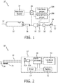
- FIG. 1 is an exploded schematic view of and FIG. 2 is a schematic diagram of a power toothbrush 10 according to an exemplary embodiment of the present invention.
- toothbrush 10 is structured to detect brushing force at a plurality of angles which, unlike prior art toothbrushes that may have a single force sensor, allows for the brushhead angle, and thus the brushing angle, to be derived.
- Toothbrush 10 includes a handle portion 12 and a DC motor 14 which is powered by a battery 16. Motor 14 provides the driving action for a brushhead 18, which in turn is removably mounted on a motor driveshaft 22. It should be understood, however, that various alternative driving action arrangements may be used in a power toothbrush which incorporates the concept disclosed herein.
- the illustration of a DC motor in the exemplary embodiment is only one of several possible motor systems.
- Brushhead 18 includes a set of bristles 24 mounted on a bristle back member 25 which together define the bristle portion of brushhead 18. Bristles 24 accomplish cleaning through an oscillatory action provided to brushhead 18 by motor 14.
- the operation of motor 14 is controlled by a processing unit 26, which is a common component of power toothbrushes.
- Processing unit 26 may be, for example and without limitation, a microprocessor, a microcontroller, or any other suitable processing device and may include a suitable memory for storing routines executed by processing unit 26.
- handle portion 12 includes a first force sensor 30A for measuring the brushing force exerted by brushhead 18 against the teeth during use of toothbrush 10 at a first angle relative to a longitudinal axis 32 of toothbrush 10 and a longitudinal axis 36 of bristles 24 (as indicated by arrow in FIG. 2 ), and a second force sensor 30B for measuring the brushing force exerted by brushhead 18 against the teeth during use of toothbrush 10 at a second angle relative to the longitudinal axis 32 of toothbrush 10 and longitudinal axis 36 of bristles 24 (different than the first axis).
- first force sensor 30A and second source sensor 30B are located adjacent to motor 14 and are structured to measure the force on driveshaft 22.
- first force sensor 30A and second source sensor 30B are structured and positioned to measure brushing forces at two different angles.
- first force sensor 30A may be structured and positioned to measure brushing force substantially perpendicular to the longitudinal axis 32 of toothbrush 10 and substantially parallel to the longitudinal axis 36 of bristles 24
- second force sensor 30B may be structured and positioned to measure brushing force substantially parallel to the longitudinal axis 32 and substantially perpendicular to the longitudinal axis 36 of bristles 24.
- this configuration is meant to be exemplary only, and that alternative angles for each force sensor 30A and 30B are also possible within the scope of the concept disclosed herein.
- a number of exemplary alternative configurations for force sensors 30A and 30B are described in detail elsewhere herein.
- first force sensor 30A and second force sensor 30B are each operatively coupled to processing unit 26 and provide a signal to processing unit 26 indicative of the force measured thereby.
- force sensors 30A and 30B may be located in brushhead 18.
- the former configuration wherein force sensors 30A and 30B are located within handle portion 12 will help to keep the cost of brushhead 18 down and will avoid interconnection issues across the pluggable interface between brushhead 18 and handle portion 12.
- First force sensor 30A and second force sensor 30B may be any of a number of known or hereafter developed suitable sensing devices for sensing the force exerted by brushhead 18.
- first force sensor 30A and second force sensor 30B may each be a strain gauge structured to directly measure the brushing force or a sensor, such as a magnetic (Hall) sensor, which indirectly measures the brushing force by measuring the displacement of brushhead 18 and/or motor driveshaft 22.
- a magnetic (Hall) sensor which indirectly measures the brushing force by measuring the displacement of brushhead 18 and/or motor driveshaft 22.
- handle portion 12 also includes a feedback device 34 that is coupled to processing unit 26.
- feedback device 34 is structured to provide user perceptible feedback regarding the brushing angle with respect to the tooth surfaces (i.e., the brushing angle at which bristles 24 are positioned) that the user is employing at any particular time.
- the user perceptible feedback generated by feedback device 34 is designed to encourage the user to brush at a favorable brushing angle. A number of manners in which the brushing angle and or feedback may be determined and/or provided are described in detail herein.
- Feedback device 34 may be an audible feedback device, such as a speaker, that is structured to generate an audible feedback signal under the control of processing unit 26.
- feedback device 34 may be a visual feedback device, such as one or more LEDs, that is/are structured to generate a visual feedback signal under the control of processing unit 26.
- the feedback may be implemented by processing unit 26 modifying the motor drive mode of motor 14 to give a different sensation in the user's mouth, such as a lowered amplitude, a pulsing of the motor 14, or some other alternation of the motor vibration. Such a feedback mechanism may be more easily perceived by the user.
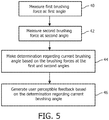
- FIG. 5 is a flowchart illustrating a method of operation of toothbrush 10 according to an exemplary embodiment of the disclosed concept wherein a determination of current brushing angle is made/derived based upon brushing forces that are measured at two or more different angles and wherein, in response thereto, feedback is provided to the user of toothbrush 10 in order to encourage a preferred brushing angle.
- the method begins at step 40, wherein a first brushing force is measured at a first angle by first force sensor 30A (referred to herein as F 1 ). Then, at step 42, a second brushing force is measured at a second angle different than the first angle by second force sensor 30B (referred to herein as F 2 ).
- F 1 first angle by first force sensor 30A
- F 2 second force sensor 30B
- the first and second brushing forces measured at step 40 and 42 are provided to processing unit 26.
- processing unit 26 makes a determination regarding the current brushing angle based on the first and second brushing forces that were measured at step 40 and 42.
- the determination made at step 44 is a determination as to the degree to which the brushing angle is something other than substantially perpendicular to the surface of the teeth (i.e., the degree of rotation of brushhead 18 and in particular bristles 24 and bristle back member 25 about longitudinal axis 32 during brushing).
- step 44 may involve determining whether, based on the first and second brushing forces, the brushing angle is within an ideal range, a non-ideal yet still acceptable range, or an unacceptable range.
- step 44 may involve determining whether the brushing angle is above or below a suitable predetermined threshold for acceptable angle. Still other examples are within the scope of the disclosed concept.
- processing unit 26 causes a user perceptible feedback to be generated through feedback device 34 based on the determination made in step 44.
- the user perceptible feedback may be causing a particularly colored LED or LEDs forming part of feedback device 34 to be lit and/or may be causing an audible signal of a particular nature to be generated feedback device 34 (for instance, a buzzing sound may be generated in the case where the brushing angle is determined to be in an unacceptable range and/or below a suitable predetermined threshold).
- first force sensor 30A is structured to measure a force F 1 at a first angle, namely substantially perpendicular to the longitudinal axis 32 and substantially parallel to the longitudinal axis 36 of bristles 24 and second force sensor 30B is structured to measure a force F 2 at a second angle, namely substantially parallel to longitudinal axis 32 and substantially perpendicular to the longitudinal axis 36 of bristles 24.
- the determination regarding current brushing angle can be made using the case analysis shown in TABLE 1 below, wherein F T is a typical brushing force of the user of, for example and without limitation, 1-3 N.
- processing unit 26 determines that the current brushing of the user falls within Case 3 or Case 4, and thus that the brushing angle is unfavorable and/or unacceptable, then processing unit 26 will, in the exemplary embodiment, cause feedback device 34 to provide a corrective signal to the user, such as an alarm sound or a light of a particular color, in order to encourage the user to brush at a better angle.
- a corrective signal such as an alarm sound or a light of a particular color
- the proposed figure of merit is the ratio of the measured forces F 1 (F 1 +F 2 ).
- the case analysis described above may, in one particular embodiment, be implemented based on the information/formulas provided in TABLE 2 below.
- TABLE 2 F 1 / (F 1 +F 2 ) Ratio Determination regarding current brushing angle F 1 /(F 1 +F 2 ) > Threshold 1 ideal brushing (green LED lit) Threshold 2 ⁇ F 1 /(F 1 +F 2 ) ⁇ Threshold 1 non-ideal brushing (orange LED lit) F 1 /(F 1 +F 2 ) ⁇ Threshold 2 bad brushing (red LED lit)
- the case analysis described above may be implemented based upon and using a single feedback formula as follows: if F 1 /(F 1 +F 2 ) ⁇ Thresholds: bad brushing (red LED lit and/or buzzer sound activated); otherwise brushing angle acceptable.
- Threshold 3 0.65.
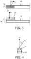
- first force sensor 30A is structured to measure a force F 1 at a first angle, namely substantially perpendicular to the longitudinal axis 32 and substantially parallel to the longitudinal axis 36 of bristles 24 and second force sensor 30B is structured to measure a force F 2 at a second angle, namely substantially perpendicular to the longitudinal axis 36 of bristles 24 and not substantially perpendicular to longitudinal axis 32, at an angle ⁇ 1 (as demonstrated in FIG. 3 ).
- a reduction factor of about the cosine of ⁇ 1 is applied and the case analysis described herein may be implemented based on the information/formulas provided in TABLE 3 below.
- the case analysis in this alternative may be implemented based upon and using the single feedback formula as follows: if F 1 /(F 1 +F 2 /cos ⁇ 1 ) ⁇ Thresholds: bad brushing (red LED lit and/or buzzer sound activated); otherwise brushing angle acceptable.
- first force sensor 30A is structured to measure a force F 1 at a first angle, namely substantially perpendicular to the longitudinal axis 32 and substantially parallel to the longitudinal 36 axis of bristles 24 and second force sensor 30B is structured to measure a force F 2 at a second angle, namely not substantially perpendicular to the longitudinal axis 36 of bristles 24, at an angle ⁇ 2 , and substantially perpendicular to longitudinal axis 32 (as demonstrated in FIG. 4 ).
- a reduction factor of about the sine of ⁇ 2 is applied and the case analysis described herein may be implemented based on the information/formulas provided in TABLE 4 below.
- the case analysis in this alternative may be implemented based upon and using the single feedback formula as follows: F 1 /(F 1 +F 2 /sin ⁇ 2 ) ⁇ Thresholds: bad brushing (red LED lit and/or buzzer sound activated); otherwise brushing angle acceptable.
- first force sensor 30A and second force sensor 30B are both positioned not substantially perpendicular to longitudinal axis 36 of bristles 24. In this case, it may be advantageous if both first and second force sensors 30A and 30B have the same angle relative to longitudinal axis 36 of bristles 24.
- the force measured by each of the first and second force sensors 30A and 30B will be substantially equal (i.e., the normalized signal (F 1 -F 2 )/ (F 1 +F 2 ) ⁇ 0) if the user is brushing substantially perpendicular to the tooth (ideal case), whilst the brushing angle will increase (i.e.
- feedback may be generated which indicates a poor brushing angle (e.g., red LED lit and/or buzzer sound activated) when the absolute value of the force difference (F 1 -F 2 ) exceeds some predetermined threshold value.
- a different feedback signal e.g., green LED lit and/or alternative, positive buzzer sound activated
- indicating a good brushing angle may be provided when the absolute value of the force difference (F 1 -F 2 )/(F 1 +F 2 ) is less than or equal to the predetermined threshold value.
- multiple threshold values can be used, such that e.g. green, orange or red feedback can be given.
- the relevant figure of merit may be judged at absolute force levels above a certain threshold value of, for example and without limitation, 0.25 N. Otherwise, feedback may be given when the brushhead 18 is not really in contact with the teeth.
- first force sensor 30A and second force sensor 30B when the brushing action of toothbrush 10 is primarily on the teeth, the readings of first force sensor 30A and second force sensor 30B will, as described herein, provide a good indication of the current brushing angle. However, when the brushing action of toothbrush 10 is on the gum line, readings from first force sensor 30A and second force sensor 30B may nonetheless falsely indicate ideal brushing angles (e.g., F 1 /F 2 > 0.8) because the position of toothbrush 10 on the gums may yield a dominant signal from the first force sensor 30A (F 1 ) due to the gum orientation.
- ideal brushing angles e.g., F 1 /F 2 > 0.8
- WO 2014/097242 describes a system wherein signals from a stream probe may be used to obtain information indicating that a brushhead is on the gums. Using this information, more optimized feedback of brushhead orientation according to the concept disclosed herein may be provided.
- an indication that brushhead 18 is positioned on the gums obtained in the manner described in WO 2014/097242 may be used as a check for situations wherein readings from first force sensor 30A and second force sensor 30B indicate ideal brushing angles, such that if such readings indicate ideal brushing angles yet it is determined that brushhead 18 is on the gums, feedback indicating ideal brushing angles will not be provided.
- toothbrush 10 shown in FIGS. 1 and 2 and the method of operation shown in FIG. 3 provide a system wherein users may be automatically encouraged to employ preferred brushing angles to increase brushing effectiveness and efficiency.
- any reference signs placed between parentheses shall not be construed as limiting the claim.
- the word “comprising” or “including” does not exclude the presence of elements or steps other than those listed in a claim.
- several of these means may be embodied by one and the same item of hardware.
- the word “a” or “an” preceding an element does not exclude the presence of a plurality of such elements.
- any device claim enumerating several means several of these means may be embodied by one and the same item of hardware.
- the mere fact that certain elements are recited in mutually different dependent claims does not indicate that these elements cannot be used in combination.
Description
- The present invention pertains to toothbrushes, and, in particular, to a toothbrush, such as a power toothbrush, structured to detect brushing angle and provide feedback to the user based on brushing force detected at a plurality of angles.
- In general, power toothbrushes for cleaning teeth, including removal of plaque, are well known. Typically, power toothbrushes rely on a set of bristles which are attached to a bristle mounting plate, which in turn is moved by a driver mechanism to scrub the surfaces of teeth. Such toothbrushes, which rely on scrubbing action of the bristles for actual cleaning, typically require some amount of force to be exerted by the user against the teeth to accommodate differences in the various shapes and spacing of the teeth and to effectively clean the teeth.
- Correct positioning of the bristles of a toothbrush relative to the teeth is essential for efficient plaque removal. To best remove plaque from the teeth, it is often advantageous to brush with the bristles positioned at an angle fairly perpendicular to the tooth. Trials have revealed that users regularly brush their teeth at angle far from the perpendicular. Angles of up to 70 degrees from the perpendicular are common, especially when brushing the inside of the teeth. At such extreme angles, many of the bristles are no longer in contact with the teeth (or are at an inefficient angle) and brushing is extremely inefficient.
-
WO 02/15742 -
US 6,536,068 discloses methods for monitoring toothbrush technique, for example a method including, while a toothbrush user is brushing his teeth, acquiring data indicative of motion of the toothbrush along its longitudinal axis, and providing information about the data for display. - In one embodiment, a toothbrush is provided that has a first longitudinal axis and that comprises a brushhead including a set of bristles having a second longitudinal axis different than the first longitudinal axis, a first force sensor for measuring a first force exerted by the brushhead against the teeth during use of the toothbrush at a first angle relative to the first longitudinal axis and the second longitudinal axis, a second force sensor for measuring a second force exerted by the brushhead against the teeth during use of the toothbrush at a second angle relative to the first longitudinal axis and the second longitudinal axis, the second angle being different than the first angle, and a processing unit. The processing unit is structured to: (i) receive first information indicative of the first force as measured by the first force sensor, (ii) receive second information indicative of the second force as measured by the second force sensor, and (iii) determine information regarding a current brushing angle of the brushhead, i.e. a current angle of the bristles with respect to the tooth surfaces, based on the first information and the second information.
- These and other objects, features, and characteristics of the present invention, as well as the methods of operation and functions of the related elements of structure and the combination of parts and economies of manufacture, will become more apparent upon consideration of the following description and the appended claims with reference to the accompanying drawings, all of which form a part of this specification, wherein like reference numerals designate corresponding parts in the various figures. It is to be expressly understood, however, that the drawings are for the purpose of illustration and description only and are not intended as a definition of the limits of the invention.
-
-
FIG. 1 is an exploded schematic view of a toothbrush according to an exemplary embodiment of the present invention; -
FIG. 2 is a schematic diagram of the toothbrush ofFIG. 1 ; -
FIGS. 3 and 4 are schematic diagrams illustrating two alternative particular implementations of the toothbrush head ofFIGS. 1 and 2 ; and -
FIG. 5 is a flowchart illustrating operation of the toothbrush ofFIGS. 1 and 2 according to one exemplary embodiment. - As used herein, the singular form of "a", "an", and "the" include plural references unless the context clearly dictates otherwise. As used herein, the statement that two or more parts or components are "coupled" shall mean that the parts are joined or operate together either directly or indirectly, i.e., through one or more intermediate parts or components, so long as a link occurs. As used herein, "directly coupled" means that two elements are directly in contact with each other. As used herein, "fixedly coupled" or "fixed" means that two components are coupled so as to move as one while maintaining a constant orientation relative to each other.
- As used herein, the word "unitary" means a component is created as a single piece or unit. That is, a component that includes pieces that are created separately and then coupled together as a unit is not a "unitary" component or body. As employed herein, the statement that two or more parts or components "engage" one another shall mean that the parts exert a force against one another either directly or through one or more intermediate parts or components. As employed herein, the term "number" shall mean one or an integer greater than one (i.e., a plurality).
- As used herein, "substantially perpendicular" shall mean at an angle of 90 degrees ± 5 degrees.
- As used herein, "substantially parallel" shall mean at an angle of 0 degrees ± 5 degrees.
- Directional phrases used herein, such as, for example and without limitation, top, bottom, left, right, upper, lower, front, back, and derivatives thereof, relate to the orientation of the elements shown in the drawings and are not limiting upon the claims unless expressly recited therein.
-
FIG. 1 is an exploded schematic view of andFIG. 2 is a schematic diagram of apower toothbrush 10 according to an exemplary embodiment of the present invention. As described in detail herein,toothbrush 10 is structured to detect brushing force at a plurality of angles which, unlike prior art toothbrushes that may have a single force sensor, allows for the brushhead angle, and thus the brushing angle, to be derived. Toothbrush 10 includes ahandle portion 12 and aDC motor 14 which is powered by abattery 16. Motor 14 provides the driving action for abrushhead 18, which in turn is removably mounted on amotor driveshaft 22. It should be understood, however, that various alternative driving action arrangements may be used in a power toothbrush which incorporates the concept disclosed herein. The illustration of a DC motor in the exemplary embodiment is only one of several possible motor systems. - Brushhead 18 includes a set of
bristles 24 mounted on abristle back member 25 which together define the bristle portion ofbrushhead 18.Bristles 24 accomplish cleaning through an oscillatory action provided to brushhead 18 bymotor 14. The operation ofmotor 14 is controlled by aprocessing unit 26, which is a common component of power toothbrushes.Processing unit 26 may be, for example and without limitation, a microprocessor, a microcontroller, or any other suitable processing device and may include a suitable memory for storing routines executed byprocessing unit 26. - As seen in
FIGS. 1 and 2 , in the exemplary embodiment,handle portion 12 includes afirst force sensor 30A for measuring the brushing force exerted bybrushhead 18 against the teeth during use oftoothbrush 10 at a first angle relative to alongitudinal axis 32 oftoothbrush 10 and alongitudinal axis 36 of bristles 24 (as indicated by arrow inFIG. 2 ), and asecond force sensor 30B for measuring the brushing force exerted bybrushhead 18 against the teeth during use oftoothbrush 10 at a second angle relative to thelongitudinal axis 32 oftoothbrush 10 andlongitudinal axis 36 of bristles 24 (different than the first axis). In the exemplary embodiment,first force sensor 30A andsecond source sensor 30B are located adjacent tomotor 14 and are structured to measure the force ondriveshaft 22. Thus,first force sensor 30A andsecond source sensor 30B are structured and positioned to measure brushing forces at two different angles. For example,first force sensor 30A may be structured and positioned to measure brushing force substantially perpendicular to thelongitudinal axis 32 oftoothbrush 10 and substantially parallel to thelongitudinal axis 36 ofbristles 24 andsecond force sensor 30B may be structured and positioned to measure brushing force substantially parallel to thelongitudinal axis 32 and substantially perpendicular to thelongitudinal axis 36 ofbristles 24. It will be appreciated, however, that this configuration is meant to be exemplary only, and that alternative angles for eachforce sensor force sensors FIGS. 1 and 2 ,first force sensor 30A andsecond force sensor 30B are each operatively coupled toprocessing unit 26 and provide a signal to processingunit 26 indicative of the force measured thereby. In an alternative embodiment,force sensors force sensors handle portion 12 will help to keep the cost ofbrushhead 18 down and will avoid interconnection issues across the pluggable interface betweenbrushhead 18 andhandle portion 12. -
First force sensor 30A andsecond force sensor 30B may be any of a number of known or hereafter developed suitable sensing devices for sensing the force exerted bybrushhead 18. For example, and without limitation,first force sensor 30A andsecond force sensor 30B may each be a strain gauge structured to directly measure the brushing force or a sensor, such as a magnetic (Hall) sensor, which indirectly measures the brushing force by measuring the displacement ofbrushhead 18 and/ormotor driveshaft 22. - The measured force values generated by
first force sensor 30A andsecond force sensor 30B are provided toprocessing unit 26. Furthermore, as seen inFIGS. 1 and 2 ,handle portion 12 also includes afeedback device 34 that is coupled toprocessing unit 26. As described in greater detail herein, during use oftoothbrush 10,feedback device 34 is structured to provide user perceptible feedback regarding the brushing angle with respect to the tooth surfaces (i.e., the brushing angle at whichbristles 24 are positioned) that the user is employing at any particular time. The user perceptible feedback generated byfeedback device 34 is designed to encourage the user to brush at a favorable brushing angle. A number of manners in which the brushing angle and or feedback may be determined and/or provided are described in detail herein.Feedback device 34 may be an audible feedback device, such as a speaker, that is structured to generate an audible feedback signal under the control ofprocessing unit 26. Alternatively,feedback device 34 may be a visual feedback device, such as one or more LEDs, that is/are structured to generate a visual feedback signal under the control ofprocessing unit 26. In still another alternative embodiment, the feedback may be implemented by processingunit 26 modifying the motor drive mode ofmotor 14 to give a different sensation in the user's mouth, such as a lowered amplitude, a pulsing of themotor 14, or some other alternation of the motor vibration. Such a feedback mechanism may be more easily perceived by the user. -
FIG. 5 is a flowchart illustrating a method of operation oftoothbrush 10 according to an exemplary embodiment of the disclosed concept wherein a determination of current brushing angle is made/derived based upon brushing forces that are measured at two or more different angles and wherein, in response thereto, feedback is provided to the user oftoothbrush 10 in order to encourage a preferred brushing angle. The method begins atstep 40, wherein a first brushing force is measured at a first angle byfirst force sensor 30A (referred to herein as F1). Then, atstep 42, a second brushing force is measured at a second angle different than the first angle bysecond force sensor 30B (referred to herein as F2). The first and second brushing forces measured atstep processing unit 26. Next, atstep 44, processingunit 26 makes a determination regarding the current brushing angle based on the first and second brushing forces that were measured atstep step 44 is a determination as to the degree to which the brushing angle is something other than substantially perpendicular to the surface of the teeth (i.e., the degree of rotation ofbrushhead 18 and inparticular bristles 24 and bristle backmember 25 aboutlongitudinal axis 32 during brushing). For example, and without limitation, step 44 may involve determining whether, based on the first and second brushing forces, the brushing angle is within an ideal range, a non-ideal yet still acceptable range, or an unacceptable range. As another, simpler example, step 44 may involve determining whether the brushing angle is above or below a suitable predetermined threshold for acceptable angle. Still other examples are within the scope of the disclosed concept. Finally, atstep 46, processingunit 26 causes a user perceptible feedback to be generated throughfeedback device 34 based on the determination made instep 44. For example, and without limitation, the user perceptible feedback may be causing a particularly colored LED or LEDs forming part offeedback device 34 to be lit and/or may be causing an audible signal of a particular nature to be generated feedback device 34 (for instance, a buzzing sound may be generated in the case where the brushing angle is determined to be in an unacceptable range and/or below a suitable predetermined threshold). - A number of non-limiting, exemplary implementations of the method of
FIG. 5 will now be described in detail. It will be understood, however, that the implementations described below are meant to be exemplary only and thus are not to be considered limiting. - In a first exemplary implementation,
first force sensor 30A is structured to measure a force F1 at a first angle, namely substantially perpendicular to thelongitudinal axis 32 and substantially parallel to thelongitudinal axis 36 ofbristles 24 andsecond force sensor 30B is structured to measure a force F2 at a second angle, namely substantially parallel tolongitudinal axis 32 and substantially perpendicular to thelongitudinal axis 36 ofbristles 24. In this exemplary implementation, the determination regarding current brushing angle can be made using the case analysis shown in TABLE 1 below, wherein FT is a typical brushing force of the user of, for example and without limitation, 1-3 N.TABLE 1 Use Case F1 value F2 value Determination regarding current brushing angle Case 1 FT 0 Brushing is perpendicular to the tooth surface - Ideal brushing Case 2 ∼ FT >0 Brushing is not perpendicular to the tooth surface - Non ideal but still acceptable brushing Case 3 < FT >> 0 Brushing is not perpendicular to the tooth surface - Less than acceptable (i.e., inefficient) brushing Case 4 << FT F2 >>>0 Brushing is at a very high angle to the tooth surface - Very inefficient brushing - Based on the case analysis described above, if processing
unit 26 determines that the current brushing of the user falls within Case 3 or Case 4, and thus that the brushing angle is unfavorable and/or unacceptable, then processingunit 26 will, in the exemplary embodiment, causefeedback device 34 to provide a corrective signal to the user, such as an alarm sound or a light of a particular color, in order to encourage the user to brush at a better angle. - In the case analysis described above, the proposed figure of merit is the ratio of the measured forces F1(F1 +F2). Thus, the case analysis described above may, in one particular embodiment, be implemented based on the information/formulas provided in TABLE 2 below.
TABLE 2 F1/ (F1+F2) Ratio Determination regarding current brushing angle F1/(F1+F2) > Threshold1 ideal brushing (green LED lit) Threshold2 ≤ F1/(F1+F2) ≤ Threshold1 non-ideal brushing (orange LED lit) F1/(F1+F2) < Threshold2 bad brushing (red LED lit) - In one particular, non-limiting embodiment, Threshold1 = 0.8 and Threshold2 = 0.5. In a simplified example, the case analysis described above may be implemented based upon and using a single feedback formula as follows: if F1/(F1+F2) < Thresholds: bad brushing (red LED lit and/or buzzer sound activated); otherwise brushing angle acceptable. In one particular, non-limiting embodiment, Threshold3 = 0.65.
- In a second exemplary implementation of
toothbrush 10, shown schematically inFIG. 3 ,first force sensor 30A is structured to measure a force F1 at a first angle, namely substantially perpendicular to thelongitudinal axis 32 and substantially parallel to thelongitudinal axis 36 ofbristles 24 andsecond force sensor 30B is structured to measure a force F2 at a second angle, namely substantially perpendicular to thelongitudinal axis 36 ofbristles 24 and not substantially perpendicular tolongitudinal axis 32, at an angle α1 (as demonstrated inFIG. 3 ). In this second alternative exemplary implementation, a reduction factor of about the cosine of α1 is applied and the case analysis described herein may be implemented based on the information/formulas provided in TABLE 3 below.TABLE 3 F1/(F1+F2/cos α1) Ratio Determination regarding current brushing angle F1/(F1+F2/cos α1) > Threshold1 ideal brushing (green LED lit) Threshold2 ≤ F1/(F1+F2/cos α1) ≤ Threshold1 non-ideal brushing (orange LED lit) F1/(F1+F2/cos α1) < Threshold2 bad brushing (red LED lit) - In a simplified example, the case analysis in this alternative may be implemented based upon and using the single feedback formula as follows: if F1/(F1+F2/cos α1) < Thresholds: bad brushing (red LED lit and/or buzzer sound activated); otherwise brushing angle acceptable.
- In a third exemplary implementation of
toothbrush 10, shown schematically inFIG. 4 ,first force sensor 30A is structured to measure a force F1 at a first angle, namely substantially perpendicular to thelongitudinal axis 32 and substantially parallel to the longitudinal 36 axis ofbristles 24 andsecond force sensor 30B is structured to measure a force F2 at a second angle, namely not substantially perpendicular to thelongitudinal axis 36 ofbristles 24, at an angle α2, and substantially perpendicular to longitudinal axis 32 (as demonstrated inFIG. 4 ). In this third alternative exemplary implementation, a reduction factor of about the sine of α2 is applied and the case analysis described herein may be implemented based on the information/formulas provided in TABLE 4 below.TABLE 4 F1/(F1+F2/sinα1) Ratio Determination regarding current brushing angle F1/(F1+F2/sinα2) > Threshold1 ideal brushing (green LED lit) Threshold2 ≤ F1/(F1+F2/sinα2) ≤ Threshold1 non-ideal brushing (orange LED lit) F1/(F1+F2/sinα2) < Threshold2 bad brushing (red LED lit) - In a simplified example, the case analysis in this alternative may be implemented based upon and using the single feedback formula as follows:
F1/(F1+F2/sinα2) < Thresholds: bad brushing (red LED lit and/or buzzer sound activated); otherwise brushing angle acceptable. - In a fourth exemplary implementation,
first force sensor 30A andsecond force sensor 30B are both positioned not substantially perpendicular tolongitudinal axis 36 ofbristles 24. In this case, it may be advantageous if both first andsecond force sensors longitudinal axis 36 ofbristles 24. The force measured by each of the first andsecond force sensors - Furthermore, in the first, second, third and fourth implementations just described, it may be advantageous for the relevant figure of merit to only be judged at absolute force levels above a certain threshold value of, for example and without limitation, 0.25 N. Otherwise, feedback may be given when the
brushhead 18 is not really in contact with the teeth. - Moreover, when the brushing action of
toothbrush 10 is primarily on the teeth, the readings offirst force sensor 30A andsecond force sensor 30B will, as described herein, provide a good indication of the current brushing angle. However, when the brushing action oftoothbrush 10 is on the gum line, readings fromfirst force sensor 30A andsecond force sensor 30B may nonetheless falsely indicate ideal brushing angles (e.g., F1/F2 > 0.8) because the position oftoothbrush 10 on the gums may yield a dominant signal from thefirst force sensor 30A (F1) due to the gum orientation. According to one exemplary, non-limiting particular implementation, this issue may be overcome by employing the concept disclosed herein in combination with the concept described inWO 2014/097242 , entitled "Plaque Detection Using A Stream Probe," owned by the assignee of the present invention, the disclosure of which is incorporated herein by reference. In particular,WO 2014/097242 describes a system wherein signals from a stream probe may be used to obtain information indicating that a brushhead is on the gums. Using this information, more optimized feedback of brushhead orientation according to the concept disclosed herein may be provided. In particular, an indication that brushhead 18 is positioned on the gums obtained in the manner described inWO 2014/097242 may be used as a check for situations wherein readings fromfirst force sensor 30A andsecond force sensor 30B indicate ideal brushing angles, such that if such readings indicate ideal brushing angles yet it is determined thatbrushhead 18 is on the gums, feedback indicating ideal brushing angles will not be provided. - Thus,
toothbrush 10 shown inFIGS. 1 and 2 and the method of operation shown inFIG. 3 provide a system wherein users may be automatically encouraged to employ preferred brushing angles to increase brushing effectiveness and efficiency. - In the claims, any reference signs placed between parentheses shall not be construed as limiting the claim. The word "comprising" or "including" does not exclude the presence of elements or steps other than those listed in a claim. In a device claim enumerating several means, several of these means may be embodied by one and the same item of hardware. The word "a" or "an" preceding an element does not exclude the presence of a plurality of such elements. In any device claim enumerating several means, several of these means may be embodied by one and the same item of hardware. The mere fact that certain elements are recited in mutually different dependent claims does not indicate that these elements cannot be used in combination.
- Although the invention has been described in detail for the purpose of illustration based on what is currently considered to be the most practical and preferred embodiments, it is to be understood that such detail is solely for that purpose and that the invention is not limited to the disclosed embodiments, but, on the contrary, is intended to cover modifications and equivalent arrangements that are within the scope of the appended claims. For example, it is to be understood that the present invention contemplates that, to the extent possible, one or more features of any embodiment can be combined with one or more features of any other embodiment.
Claims (8)
- A toothbrush (10) having a first longitudinal axis (32), comprising:a brushhead (18) including a set of bristles (24) having a second longitudinal axis (36) different than the first longitudinal axis (32);a first force sensor (30A) for measuring a first force exerted by the brushhead (18) against the teeth during use of the toothbrush (10) at a first angle relative to the first longitudinal axis (32) and the second longitudinal axis (36);a second force sensor (30B) for measuring a second force exerted by the brushhead (18) against the teeth during use of the toothbrush (10) at a second angle relative to the first longitudinal axis (32) and the second longitudinal axis (36), the second angle being different than the first angle; anda processing unit (26), the processing unit (26) being structured to: (i) receive first information indicative of the first force as measured by the first force sensor (30A), (ii) receive second information indicative of the second force as measured by the second force sensor (30B), and characterised in that the processing unit (26) is furthermore structured to (iii) determine information regarding a current angle of the bristles (24) with respect to the tooth surfaces based on the first information and the second information.
- A toothbrush (10) according to claim 1, wherein the processing unit (26) is structured to cause user perceptible feedback to be provided to a feedback device (34) based on the determined information regarding the current angle of the bristles (24) with respect to the tooth surfaces.
- A toothbrush (10) according to claim 2, wherein the feedback device (34) is structured to provide at least one of an audible output, a tactile output and a visual output.
- A toothbrush (10) according to claim 1, wherein the second longitudinal axis (36) is substantially perpendicular to the first longitudinal axis (32), wherein the first force sensor (30A) is structured and positioned to measure force substantially perpendicular to the first longitudinal axis (32) and substantially parallel to the second longitudinal axis (36), wherein the second force sensor (30B) is structured and positioned to measure force substantially parallel to the first longitudinal axis (32) and substantially perpendicular to the second longitudinal axis (36), and wherein the processing unit (26) is structured to determine the information regarding the current angle of the bristles (24) with respect to the tooth surfaces by comparing a ratio based on the first information and the second information to one or more predetermined threshold values.
- A toothbrush (10) according to claim 1, wherein the second longitudinal axis (36) is substantially perpendicular to the first longitudinal axis (32), wherein the first force sensor (30A) is structured and positioned to measure force substantially perpendicular to the first longitudinal axis (32) and substantially parallel to the second longitudinal axis (36), wherein the second force sensor (30B) is structured and positioned to measure force substantially perpendicular to the second longitudinal axis (36) and not substantially perpendicular to the first longitudinal axis (32), at an angle α1, wherein the first information is F1 and the second information is F2, and wherein the processing unit (26) is structured to determine the information regarding the current angle of the bristles (24) with respect to the tooth surfaces by comparing a ratio equal to F1/(F1+F2/cos α1) to one or more predetermined values.
- A toothbrush (10) according to claim 1, wherein the second longitudinal axis (36) is substantially perpendicular to the first longitudinal axis (32), wherein the first force sensor (30A) is structured and positioned to measure force substantially perpendicular to the first longitudinal axis (32) and substantially parallel to the second longitudinal axis (36), wherein the second force sensor (30B) is structured and positioned to measure force substantially perpendicular to the first longitudinal axis (32) and not substantially perpendicular to the second longitudinal axis (36), at an angle α2, wherein the first information is F1 and the second information is F2, and wherein the processing unit (26) is structured to determine the information regarding the current angle of the bristles (24) with respect to the tooth surfaces by comparing a ratio equal to Fi/(F1+F2/sin α2) to one or more predetermined values.
- A toothbrush (10) according to claim 1, wherein the second longitudinal axis (36) is substantially perpendicular to the first longitudinal axis (32), wherein the first force sensor (30A) and the second force sensor (30B) are both structured and positioned to measure force not substantially perpendicular to the second longitudinal axis (36), wherein the first information is F1 and the second information is F2, and wherein the processing unit (26) is structured to cause user perceptible feedback to be provided based on at least one of (i) an absolute value of a force difference (F1-F2), and (ii) an absolute value of a force difference (F1-F2)/(F1+F2).
- A toothbrush (10) according to claim 1, wherein the processing unit (26) is structured to determine the information regarding the current angle of the bristles (24) with respect to the tooth surfaces based on a ratio including the first information and the second information, and wherein the processing unit (26) is structured to determine the information regarding the current angle of the bristles (24) with respect to the tooth surfaces based on the ratio by comparing the ratio to one or more predetermined threshold values only when at least one of the first information and the second information exceeds a second predetermined threshold value.
Priority Applications (1)
| Application Number | Priority Date | Filing Date | Title |
|---|---|---|---|
| EP19184938.9A EP3583913B1 (en) | 2014-10-07 | 2015-10-05 | Toothbrush with automatic detection of brushing angle |
Applications Claiming Priority (2)
| Application Number | Priority Date | Filing Date | Title |
|---|---|---|---|
| US201462060824P | 2014-10-07 | 2014-10-07 | |
| PCT/IB2015/057613 WO2016055925A1 (en) | 2014-10-07 | 2015-10-05 | Toothbrush with automatic detection of brushing angle |
Related Child Applications (2)
| Application Number | Title | Priority Date | Filing Date |
|---|---|---|---|
| EP19184938.9A Division EP3583913B1 (en) | 2014-10-07 | 2015-10-05 | Toothbrush with automatic detection of brushing angle |
| EP19184938.9A Division-Into EP3583913B1 (en) | 2014-10-07 | 2015-10-05 | Toothbrush with automatic detection of brushing angle |
Publications (2)
| Publication Number | Publication Date |
|---|---|
| EP3203927A1 EP3203927A1 (en) | 2017-08-16 |
| EP3203927B1 true EP3203927B1 (en) | 2019-12-11 |
Family
ID=54365330
Family Applications (2)
| Application Number | Title | Priority Date | Filing Date |
|---|---|---|---|
| EP19184938.9A Active EP3583913B1 (en) | 2014-10-07 | 2015-10-05 | Toothbrush with automatic detection of brushing angle |
| EP15788206.9A Active EP3203927B1 (en) | 2014-10-07 | 2015-10-05 | Toothbrush with automatic detection of brushing angle |
Family Applications Before (1)
| Application Number | Title | Priority Date | Filing Date |
|---|---|---|---|
| EP19184938.9A Active EP3583913B1 (en) | 2014-10-07 | 2015-10-05 | Toothbrush with automatic detection of brushing angle |
Country Status (6)
| Country | Link |
|---|---|
| US (2) | US10105202B2 (en) |
| EP (2) | EP3583913B1 (en) |
| JP (1) | JP6508641B2 (en) |
| CN (1) | CN106794056B (en) |
| RU (1) | RU2695257C2 (en) |
| WO (1) | WO2016055925A1 (en) |
Families Citing this family (10)
| Publication number | Priority date | Publication date | Assignee | Title |
|---|---|---|---|---|
| CN106794056B (en) | 2014-10-07 | 2019-11-29 | 皇家飞利浦有限公司 | The automatic toothbrush for detecting angle of brushing teeth |
| JP6902478B2 (en) * | 2015-04-29 | 2021-07-14 | コーニンクレッカ フィリップス エヌ ヴェKoninklijke Philips N.V. | Systems and methods for providing angle guidance to users operating oral hygiene devices |
| SG11201912247TA (en) * | 2017-07-20 | 2020-01-30 | Procter & Gamble | Comb sensor for measuring combing resistance |
| US11684148B2 (en) * | 2017-10-13 | 2023-06-27 | Koninklijke Philips N.V. | Personal care device with high pressure indicator |
| EP3479734B1 (en) | 2017-11-02 | 2021-01-13 | Braun GmbH | Personal hygiene device |
| EP3479795B1 (en) | 2017-11-02 | 2020-05-13 | Braun GmbH | Personal hygiene device |
| US11324307B2 (en) | 2018-08-02 | 2022-05-10 | Ranir, Llc | Pressure sensing system and method for an electric toothbrush |
| EP3986328B1 (en) * | 2019-06-21 | 2023-08-09 | Koninklijke Philips N.V. | System for determining a brushing angle of an oral care device |
| CN113324850A (en) * | 2021-06-18 | 2021-08-31 | 好维股份有限公司 | Method for testing bending resistance of children toothbrush |
| TWI780903B (en) * | 2021-09-09 | 2022-10-11 | 南開科技大學 | Toothbrush monitoring device |
Family Cites Families (16)
| Publication number | Priority date | Publication date | Assignee | Title |
|---|---|---|---|---|
| US4716614A (en) * | 1985-11-07 | 1988-01-05 | Jones Arthur R | Device for monitoring the process of toothbrushing |
| US5493747A (en) * | 1993-07-27 | 1996-02-27 | Matsushita Electric Works, Ltd. | Electric toothbrush |
| DE19506129A1 (en) * | 1995-02-22 | 1996-08-29 | Gimelli & Co Ag | Toothbrush with pressure sensor |
| US6536068B1 (en) | 1999-12-29 | 2003-03-25 | Gillette Canada Company | Toothbrushing technique monitoring |
| US6425295B1 (en) * | 2000-08-21 | 2002-07-30 | Koninklijke Philips Electronics N.V. | Three point force sensing system for a toothbrush |
| US6792640B2 (en) * | 2001-06-29 | 2004-09-21 | Homedics, Inc. | Automatic electric toothbrush |
| JP5359210B2 (en) | 2008-03-14 | 2013-12-04 | オムロンヘルスケア株式会社 | electric toothbrush |
| JP5365277B2 (en) * | 2009-03-17 | 2013-12-11 | オムロンヘルスケア株式会社 | electric toothbrush |
| EP2512290B1 (en) | 2009-12-17 | 2018-04-18 | Unilever PLC | Toothbrush tracking system |
| US20130000670A1 (en) | 2011-06-28 | 2013-01-03 | Curt Binner | Toothbrush for providing substantially instant feedback |
| RU2641159C2 (en) * | 2012-08-31 | 2018-01-16 | Конинклейке Филипс Н.В. | Power sensor providing continuous feedback for toothbrush actuated by resonance using hall sensor |
| US9814552B2 (en) | 2012-12-21 | 2017-11-14 | Koninklijke Philips N.V. | Gum detection using an optical detector in a dental hygiene detection apparatus |
| BR112015015225A2 (en) * | 2012-12-28 | 2017-07-11 | Koninklijke Philips Nv | electric toothbrush with a pressure sensor |
| WO2014140959A1 (en) * | 2013-03-11 | 2014-09-18 | Koninklijke Philips N.V. | Force sensor providing continuous feedback for a resonant drive toothbrush using a hall sensor |
| JP6899768B2 (en) * | 2014-09-24 | 2021-07-07 | コーニンクレッカ フィリップス エヌ ヴェKoninklijke Philips N.V. | Systems and methods to provide motivational feedback to users prior to brushing |
| CN106794056B (en) * | 2014-10-07 | 2019-11-29 | 皇家飞利浦有限公司 | The automatic toothbrush for detecting angle of brushing teeth |
-
2015
- 2015-10-05 CN CN201580054421.5A patent/CN106794056B/en active Active
- 2015-10-05 WO PCT/IB2015/057613 patent/WO2016055925A1/en active Application Filing
- 2015-10-05 US US15/517,202 patent/US10105202B2/en active Active
- 2015-10-05 EP EP19184938.9A patent/EP3583913B1/en active Active
- 2015-10-05 JP JP2017518072A patent/JP6508641B2/en active Active
- 2015-10-05 EP EP15788206.9A patent/EP3203927B1/en active Active
- 2015-10-05 RU RU2017115656A patent/RU2695257C2/en active
-
2018
- 2018-09-19 US US16/135,364 patent/US10980624B2/en active Active
Non-Patent Citations (1)
| Title |
|---|
| None * |
Also Published As
| Publication number | Publication date |
|---|---|
| JP6508641B2 (en) | 2019-05-08 |
| JP2017529958A (en) | 2017-10-12 |
| CN106794056A (en) | 2017-05-31 |
| RU2695257C2 (en) | 2019-07-22 |
| US10105202B2 (en) | 2018-10-23 |
| EP3583913A1 (en) | 2019-12-25 |
| RU2017115656A (en) | 2018-11-19 |
| RU2017115656A3 (en) | 2019-01-28 |
| EP3583913B1 (en) | 2022-02-09 |
| US20190015182A1 (en) | 2019-01-17 |
| WO2016055925A1 (en) | 2016-04-14 |
| CN106794056B (en) | 2019-11-29 |
| US10980624B2 (en) | 2021-04-20 |
| EP3203927A1 (en) | 2017-08-16 |
| US20170312062A1 (en) | 2017-11-02 |
Similar Documents
| Publication | Publication Date | Title |
|---|---|---|
| EP3203927B1 (en) | Toothbrush with automatic detection of brushing angle | |
| US9259302B2 (en) | Pressure sensing electric toothbrush | |
| JP5838166B2 (en) | Position sensing toothbrush | |
| CN108066031B (en) | Oral care system and method | |
| JP5359210B2 (en) | electric toothbrush | |
| EP2618697B1 (en) | Force sensing toothbrush | |
| JP4543663B2 (en) | electric toothbrush | |
| US20190038014A1 (en) | Feedback device and method of providing same for users of oral care devices applying pressure during use | |
| CA2755938A1 (en) | Method for determining a pattern of use of an electric toothbrush and electric toothbrush | |
| KR101615438B1 (en) | The apparatus for sensing operation status of electric toothbrush | |
| US11051609B2 (en) | Methods and systems for optical sensing of forces in a toothbrush | |
| US10209210B2 (en) | Measuring device using electrical conductivity and having function of informing electrode contamination | |
| WO2016067151A1 (en) | Power toothbrush with automatic setting of force trigger level | |
| RU2677074C1 (en) | Methods and systems for determining location of individual care device | |
| US20220304785A1 (en) | System for determining a brushing angle of an oral care device |
Legal Events
| Date | Code | Title | Description |
|---|---|---|---|
| STAA | Information on the status of an ep patent application or granted ep patent |
Free format text: STATUS: THE INTERNATIONAL PUBLICATION HAS BEEN MADE |
|
| PUAI | Public reference made under article 153(3) epc to a published international application that has entered the european phase |
Free format text: ORIGINAL CODE: 0009012 |
|
| STAA | Information on the status of an ep patent application or granted ep patent |
Free format text: STATUS: REQUEST FOR EXAMINATION WAS MADE |
|
| 17P | Request for examination filed |
Effective date: 20170508 |
|
| AK | Designated contracting states |
Kind code of ref document: A1 Designated state(s): AL AT BE BG CH CY CZ DE DK EE ES FI FR GB GR HR HU IE IS IT LI LT LU LV MC MK MT NL NO PL PT RO RS SE SI SK SM TR |
|
| AX | Request for extension of the european patent |
Extension state: BA ME |
|
| DAV | Request for validation of the european patent (deleted) | ||
| DAX | Request for extension of the european patent (deleted) | ||
| GRAJ | Information related to disapproval of communication of intention to grant by the applicant or resumption of examination proceedings by the epo deleted |
Free format text: ORIGINAL CODE: EPIDOSDIGR1 |
|
| STAA | Information on the status of an ep patent application or granted ep patent |
Free format text: STATUS: GRANT OF PATENT IS INTENDED |
|
| GRAP | Despatch of communication of intention to grant a patent |
Free format text: ORIGINAL CODE: EPIDOSNIGR1 |
|
| INTG | Intention to grant announced |
Effective date: 20190522 |
|
| GRAS | Grant fee paid |
Free format text: ORIGINAL CODE: EPIDOSNIGR3 |
|
| GRAA | (expected) grant |
Free format text: ORIGINAL CODE: 0009210 |
|
| STAA | Information on the status of an ep patent application or granted ep patent |
Free format text: STATUS: THE PATENT HAS BEEN GRANTED |
|
| AK | Designated contracting states |
Kind code of ref document: B1 Designated state(s): AL AT BE BG CH CY CZ DE DK EE ES FI FR GB GR HR HU IE IS IT LI LT LU LV MC MK MT NL NO PL PT RO RS SE SI SK SM TR |
|
| REG | Reference to a national code |
Ref country code: GB Ref legal event code: FG4D |
|
| REG | Reference to a national code |
Ref country code: CH Ref legal event code: EP |
|
| REG | Reference to a national code |
Ref country code: AT Ref legal event code: REF Ref document number: 1211402 Country of ref document: AT Kind code of ref document: T Effective date: 20191215 |
|
| REG | Reference to a national code |
Ref country code: IE Ref legal event code: FG4D |
|
| REG | Reference to a national code |
Ref country code: DE Ref legal event code: R096 Ref document number: 602015043539 Country of ref document: DE |
|
| RAP2 | Party data changed (patent owner data changed or rights of a patent transferred) |
Owner name: KONINKLIJKE PHILIPS N.V. |
|
| REG | Reference to a national code |
Ref country code: NL Ref legal event code: MP Effective date: 20191211 |
|
| REG | Reference to a national code |
Ref country code: LT Ref legal event code: MG4D |
|
| PG25 | Lapsed in a contracting state [announced via postgrant information from national office to epo] |
Ref country code: BG Free format text: LAPSE BECAUSE OF FAILURE TO SUBMIT A TRANSLATION OF THE DESCRIPTION OR TO PAY THE FEE WITHIN THE PRESCRIBED TIME-LIMIT Effective date: 20200311 Ref country code: FI Free format text: LAPSE BECAUSE OF FAILURE TO SUBMIT A TRANSLATION OF THE DESCRIPTION OR TO PAY THE FEE WITHIN THE PRESCRIBED TIME-LIMIT Effective date: 20191211 Ref country code: LV Free format text: LAPSE BECAUSE OF FAILURE TO SUBMIT A TRANSLATION OF THE DESCRIPTION OR TO PAY THE FEE WITHIN THE PRESCRIBED TIME-LIMIT Effective date: 20191211 Ref country code: SE Free format text: LAPSE BECAUSE OF FAILURE TO SUBMIT A TRANSLATION OF THE DESCRIPTION OR TO PAY THE FEE WITHIN THE PRESCRIBED TIME-LIMIT Effective date: 20191211 Ref country code: LT Free format text: LAPSE BECAUSE OF FAILURE TO SUBMIT A TRANSLATION OF THE DESCRIPTION OR TO PAY THE FEE WITHIN THE PRESCRIBED TIME-LIMIT Effective date: 20191211 Ref country code: GR Free format text: LAPSE BECAUSE OF FAILURE TO SUBMIT A TRANSLATION OF THE DESCRIPTION OR TO PAY THE FEE WITHIN THE PRESCRIBED TIME-LIMIT Effective date: 20200312 Ref country code: NO Free format text: LAPSE BECAUSE OF FAILURE TO SUBMIT A TRANSLATION OF THE DESCRIPTION OR TO PAY THE FEE WITHIN THE PRESCRIBED TIME-LIMIT Effective date: 20200311 |
|
| PG25 | Lapsed in a contracting state [announced via postgrant information from national office to epo] |
Ref country code: HR Free format text: LAPSE BECAUSE OF FAILURE TO SUBMIT A TRANSLATION OF THE DESCRIPTION OR TO PAY THE FEE WITHIN THE PRESCRIBED TIME-LIMIT Effective date: 20191211 Ref country code: RS Free format text: LAPSE BECAUSE OF FAILURE TO SUBMIT A TRANSLATION OF THE DESCRIPTION OR TO PAY THE FEE WITHIN THE PRESCRIBED TIME-LIMIT Effective date: 20191211 |
|
| PG25 | Lapsed in a contracting state [announced via postgrant information from national office to epo] |
Ref country code: AL Free format text: LAPSE BECAUSE OF FAILURE TO SUBMIT A TRANSLATION OF THE DESCRIPTION OR TO PAY THE FEE WITHIN THE PRESCRIBED TIME-LIMIT Effective date: 20191211 |
|
| PG25 | Lapsed in a contracting state [announced via postgrant information from national office to epo] |
Ref country code: CZ Free format text: LAPSE BECAUSE OF FAILURE TO SUBMIT A TRANSLATION OF THE DESCRIPTION OR TO PAY THE FEE WITHIN THE PRESCRIBED TIME-LIMIT Effective date: 20191211 Ref country code: RO Free format text: LAPSE BECAUSE OF FAILURE TO SUBMIT A TRANSLATION OF THE DESCRIPTION OR TO PAY THE FEE WITHIN THE PRESCRIBED TIME-LIMIT Effective date: 20191211 Ref country code: PT Free format text: LAPSE BECAUSE OF FAILURE TO SUBMIT A TRANSLATION OF THE DESCRIPTION OR TO PAY THE FEE WITHIN THE PRESCRIBED TIME-LIMIT Effective date: 20200506 Ref country code: EE Free format text: LAPSE BECAUSE OF FAILURE TO SUBMIT A TRANSLATION OF THE DESCRIPTION OR TO PAY THE FEE WITHIN THE PRESCRIBED TIME-LIMIT Effective date: 20191211 Ref country code: NL Free format text: LAPSE BECAUSE OF FAILURE TO SUBMIT A TRANSLATION OF THE DESCRIPTION OR TO PAY THE FEE WITHIN THE PRESCRIBED TIME-LIMIT Effective date: 20191211 Ref country code: ES Free format text: LAPSE BECAUSE OF FAILURE TO SUBMIT A TRANSLATION OF THE DESCRIPTION OR TO PAY THE FEE WITHIN THE PRESCRIBED TIME-LIMIT Effective date: 20191211 |
|
| PG25 | Lapsed in a contracting state [announced via postgrant information from national office to epo] |
Ref country code: SK Free format text: LAPSE BECAUSE OF FAILURE TO SUBMIT A TRANSLATION OF THE DESCRIPTION OR TO PAY THE FEE WITHIN THE PRESCRIBED TIME-LIMIT Effective date: 20191211 Ref country code: IS Free format text: LAPSE BECAUSE OF FAILURE TO SUBMIT A TRANSLATION OF THE DESCRIPTION OR TO PAY THE FEE WITHIN THE PRESCRIBED TIME-LIMIT Effective date: 20200411 Ref country code: SM Free format text: LAPSE BECAUSE OF FAILURE TO SUBMIT A TRANSLATION OF THE DESCRIPTION OR TO PAY THE FEE WITHIN THE PRESCRIBED TIME-LIMIT Effective date: 20191211 |
|
| REG | Reference to a national code |
Ref country code: DE Ref legal event code: R097 Ref document number: 602015043539 Country of ref document: DE |
|
| REG | Reference to a national code |
Ref country code: AT Ref legal event code: MK05 Ref document number: 1211402 Country of ref document: AT Kind code of ref document: T Effective date: 20191211 |
|
| PLBE | No opposition filed within time limit |
Free format text: ORIGINAL CODE: 0009261 |
|
| STAA | Information on the status of an ep patent application or granted ep patent |
Free format text: STATUS: NO OPPOSITION FILED WITHIN TIME LIMIT |
|
| PG25 | Lapsed in a contracting state [announced via postgrant information from national office to epo] |
Ref country code: DK Free format text: LAPSE BECAUSE OF FAILURE TO SUBMIT A TRANSLATION OF THE DESCRIPTION OR TO PAY THE FEE WITHIN THE PRESCRIBED TIME-LIMIT Effective date: 20191211 |
|
| 26N | No opposition filed |
Effective date: 20200914 |
|
| PG25 | Lapsed in a contracting state [announced via postgrant information from national office to epo] |
Ref country code: AT Free format text: LAPSE BECAUSE OF FAILURE TO SUBMIT A TRANSLATION OF THE DESCRIPTION OR TO PAY THE FEE WITHIN THE PRESCRIBED TIME-LIMIT Effective date: 20191211 Ref country code: SI Free format text: LAPSE BECAUSE OF FAILURE TO SUBMIT A TRANSLATION OF THE DESCRIPTION OR TO PAY THE FEE WITHIN THE PRESCRIBED TIME-LIMIT Effective date: 20191211 |
|
| PG25 | Lapsed in a contracting state [announced via postgrant information from national office to epo] |
Ref country code: IT Free format text: LAPSE BECAUSE OF FAILURE TO SUBMIT A TRANSLATION OF THE DESCRIPTION OR TO PAY THE FEE WITHIN THE PRESCRIBED TIME-LIMIT Effective date: 20191211 |
|
| PG25 | Lapsed in a contracting state [announced via postgrant information from national office to epo] |
Ref country code: PL Free format text: LAPSE BECAUSE OF FAILURE TO SUBMIT A TRANSLATION OF THE DESCRIPTION OR TO PAY THE FEE WITHIN THE PRESCRIBED TIME-LIMIT Effective date: 20191211 |
|
| REG | Reference to a national code |
Ref country code: CH Ref legal event code: PL |
|
| PG25 | Lapsed in a contracting state [announced via postgrant information from national office to epo] |
Ref country code: MC Free format text: LAPSE BECAUSE OF FAILURE TO SUBMIT A TRANSLATION OF THE DESCRIPTION OR TO PAY THE FEE WITHIN THE PRESCRIBED TIME-LIMIT Effective date: 20191211 Ref country code: LU Free format text: LAPSE BECAUSE OF NON-PAYMENT OF DUE FEES Effective date: 20201005 |
|
| REG | Reference to a national code |
Ref country code: BE Ref legal event code: MM Effective date: 20201031 |
|
| PG25 | Lapsed in a contracting state [announced via postgrant information from national office to epo] |
Ref country code: CH Free format text: LAPSE BECAUSE OF NON-PAYMENT OF DUE FEES Effective date: 20201031 Ref country code: BE Free format text: LAPSE BECAUSE OF NON-PAYMENT OF DUE FEES Effective date: 20201031 Ref country code: LI Free format text: LAPSE BECAUSE OF NON-PAYMENT OF DUE FEES Effective date: 20201031 |
|
| PG25 | Lapsed in a contracting state [announced via postgrant information from national office to epo] |
Ref country code: IE Free format text: LAPSE BECAUSE OF NON-PAYMENT OF DUE FEES Effective date: 20201005 |
|
| PGFP | Annual fee paid to national office [announced via postgrant information from national office to epo] |
Ref country code: TR Payment date: 20210922 Year of fee payment: 7 |
|
| PG25 | Lapsed in a contracting state [announced via postgrant information from national office to epo] |
Ref country code: MT Free format text: LAPSE BECAUSE OF FAILURE TO SUBMIT A TRANSLATION OF THE DESCRIPTION OR TO PAY THE FEE WITHIN THE PRESCRIBED TIME-LIMIT Effective date: 20191211 Ref country code: CY Free format text: LAPSE BECAUSE OF FAILURE TO SUBMIT A TRANSLATION OF THE DESCRIPTION OR TO PAY THE FEE WITHIN THE PRESCRIBED TIME-LIMIT Effective date: 20191211 |
|
| PG25 | Lapsed in a contracting state [announced via postgrant information from national office to epo] |
Ref country code: MK Free format text: LAPSE BECAUSE OF FAILURE TO SUBMIT A TRANSLATION OF THE DESCRIPTION OR TO PAY THE FEE WITHIN THE PRESCRIBED TIME-LIMIT Effective date: 20191211 |
|
| PGFP | Annual fee paid to national office [announced via postgrant information from national office to epo] |
Ref country code: GB Payment date: 20231024 Year of fee payment: 9 |
|
| PGFP | Annual fee paid to national office [announced via postgrant information from national office to epo] |
Ref country code: FR Payment date: 20231026 Year of fee payment: 9 Ref country code: DE Payment date: 20231027 Year of fee payment: 9 |