RU2692271C2 - Skin care device - Google Patents
Skin care device Download PDFInfo
- Publication number
- RU2692271C2 RU2692271C2 RU2017124237A RU2017124237A RU2692271C2 RU 2692271 C2 RU2692271 C2 RU 2692271C2 RU 2017124237 A RU2017124237 A RU 2017124237A RU 2017124237 A RU2017124237 A RU 2017124237A RU 2692271 C2 RU2692271 C2 RU 2692271C2
- Authority
- RU
- Russia
- Prior art keywords
- skin
- friction
- skin care
- movement
- parameter
- Prior art date
Links
Images

Classifications
-
- A—HUMAN NECESSITIES
- A45—HAND OR TRAVELLING ARTICLES
- A45D—HAIRDRESSING OR SHAVING EQUIPMENT; EQUIPMENT FOR COSMETICS OR COSMETIC TREATMENTS, e.g. FOR MANICURING OR PEDICURING
- A45D26/00—Hair-singeing apparatus; Apparatus for removing superfluous hair, e.g. tweezers
- A45D26/0061—Hair-singeing apparatus; Apparatus for removing superfluous hair, e.g. tweezers with means for reducing pain during hair removal
-
- A—HUMAN NECESSITIES
- A45—HAND OR TRAVELLING ARTICLES
- A45D—HAIRDRESSING OR SHAVING EQUIPMENT; EQUIPMENT FOR COSMETICS OR COSMETIC TREATMENTS, e.g. FOR MANICURING OR PEDICURING
- A45D26/00—Hair-singeing apparatus; Apparatus for removing superfluous hair, e.g. tweezers
-
- B—PERFORMING OPERATIONS; TRANSPORTING
- B26—HAND CUTTING TOOLS; CUTTING; SEVERING
- B26B—HAND-HELD CUTTING TOOLS NOT OTHERWISE PROVIDED FOR
- B26B19/00—Clippers or shavers operating with a plurality of cutting edges, e.g. hair clippers, dry shavers
- B26B19/38—Details of, or accessories for, hair clippers, or dry shavers, e.g. housings, casings, grips, guards
- B26B19/3873—Electric features; Charging; Computing devices
- B26B19/388—Sensors; Control
-
- B—PERFORMING OPERATIONS; TRANSPORTING
- B26—HAND CUTTING TOOLS; CUTTING; SEVERING
- B26B—HAND-HELD CUTTING TOOLS NOT OTHERWISE PROVIDED FOR
- B26B19/00—Clippers or shavers operating with a plurality of cutting edges, e.g. hair clippers, dry shavers
- B26B19/38—Details of, or accessories for, hair clippers, or dry shavers, e.g. housings, casings, grips, guards
- B26B19/48—Accessory implements for carrying out a function other than cutting hair, e.g. attachable appliances for manicuring
Abstract
Description
ОБЛАСТЬ ТЕХНИКИ, К КОТОРОЙ ОТНОСИТСЯ ИЗОБРЕТЕНИЕTECHNICAL FIELD TO WHICH INVENTION RELATES.
Изобретение относится к устройству для ухода за кожей, содержащему элемент для ухода за кожей для выполнения обработки кожи, контактирующую с кожей поверхность, отдельную от элемента для ухода за кожей, для контактирования с обрабатываемой кожей, установочный элемент для установки элемента для ухода за кожей и контактирующей с кожей поверхности в устройстве для ухода за кожей, и средства управления трением, выполненные и расположенные с возможностью управления трением между контактирующей с кожей поверхностью и обрабатываемой кожей, в по меньшей мере одной области управляемого трения контактирующей с кожей поверхности, во время использования, когда контактирующую с кожей поверхность перемещается по коже.The invention relates to a skin care device comprising a skin care element for performing skin treatment, a skin contacting surface separate from the skin care element for contacting the treated skin, a mounting member for installing the skin care element and a contacting skin surface in a skin care device, and friction controls made and positioned to control the friction between the skin-contacting surface and the skin to be treated, in at least one area of controlled friction of the skin-contacting surface, during use, when the skin-contacting surface moves along the skin.
ПРЕДШЕСТВУЮЩИЙ УРОВЕНЬ ТЕХНИКИPRIOR ART
WO 2013/140309 A1 раскрывает бритву, содержащую режущий элемент и предохранительный элемент, имеющий взаимодействующий с кожей участок. Взаимодействующий с кожей участок содержит создающий усилие элемент, который может выборочно активироваться во время использования для увеличения или уменьшения усилия притяжения, прикладываемого к коже пользователя. Создающий усилие элемент может содержать электроадгезивные элементы, причем может быть предусмотрен контроллер для выборочной активации этих элементов.WO 2013/140309 A1 discloses a razor comprising a cutting member and a safety member having a portion interacting with the skin. The skin-interacting area contains a force-generating element that can be selectively activated during use to increase or decrease the force of attraction applied to the skin of the user. The force-generating element may contain electroadhesive elements, and a controller may be provided for selectively activating these elements.
В области электрического и лазерного бритья, всегда имеет место баланс между близостью процесса бритья и раздражением кожи. Этот баланс управляется величиной выступания кожи, возникающего, когда бритва перемещается по поверхности кожи, причем выступание кожи задается в виде деформации кожи через отверстия для входа волосков в сцепляющемся с кожей участке. На выступание кожи очень влияет характер трения кожи, а также локальные механические свойства кожи и характеристики использования устройства, например, нагрузка и скорость перемещения. WO 2013/140309 A1 описывает образ управления трением кожи для осуществления оптимального случая, в котором кожа может растягиваться с помощью большего трения на переднем крае взаимодействующего с кожей участка и меньшего трения (скольжения кожи) на заднем крае взаимодействующего с кожей участка, и в котором локальное задание трения может управляться в зависимости от направления перемещения бритвы по коже. В бритве, известной из WO 2013/140309 A1, управление трением достигается посредством выборочной активации создающего усилие элемента взаимодействующего с кожей участка во время использования для регулирования усилия притяжения к коже пользователя.In the field of electric and laser shaving, there is always a balance between the proximity of the shaving process and skin irritation. This balance is governed by the amount of protrusion of the skin that occurs when the razor moves over the skin's surface, and the protrusion of the skin is defined as the deformation of the skin through the hair entry holes in the skin-bonding area. The protrusion of the skin is greatly influenced by the nature of the friction of the skin, as well as the local mechanical properties of the skin and the characteristics of the use of the device, for example, the load and speed of movement. WO 2013/140309 A1 describes the image of controlling friction of the skin for the implementation of an optimal case in which the skin can stretch using more friction on the front edge of the area interacting with the skin and less friction (skin sliding) on the back edge of the area interacting with the skin and in which the friction task can be controlled depending on the direction of movement of the razor over the skin. In a razor known from WO 2013/140309 A1, friction control is achieved by selectively activating the force-generating element of the skin-engaging area during use to regulate the force of attraction to the user's skin.
ЕР 1 764 010A1 раскрывает электрическую бритву, содержащую бреющую насадку, имеющую первый срезающий волоски элемент для срезания длинных волосков и второй срезающий волоски элемент для срезания коротких волосков, причем, если смотреть в направлении движения бритвы по коже, первый срезающий волоски элемент расположен спереди второго срезающего элемента. Бреющая насадка дополнительно содержит очищающий кожу элемент, который расположен позади первого и второго срезающих элементов, если смотреть в направлении движения. Очищающий кожу элемент содержит овальный очищающий кожу элемент, который проходит перпендикулярно относительно направления движения, и приводные средства для возвратно-поступательного перемещения очищающего кожу элемента в его направлении протяженности.EP 1 764 010A1 discloses an electric razor comprising a shaving head having a first hair cutting element for cutting long hairs and a second hair cutting element for cutting short hairs, and, when viewed in the direction of the razor’s movement, the first hair cutting element an item. The shaver head further comprises a skin cleansing element that is located behind the first and second shearing elements, when viewed in the direction of travel. The skin cleansing element contains an oval skin cleansing element, which runs perpendicular to the direction of movement, and drive means for reciprocating movement of the skin cleansing element in its length direction.
FR 2 810 516 A1 раскрывает устройство для эпиляции, содержащее вращаемый цилиндр для эпиляции с взаимодействующими зажимными элементами для зажатия волосков и удаления волосков из кожи. Устройство для эпиляции содержит овальный контактирующий с кожей элемент, который расположен рядом с цилиндром для эпиляции и проходит перпендикулярно относительно цилиндра для эпиляции и который находится в контакте с кожей во время использования устройства для эпиляции. Устройство для эпиляции дополнительно содержит приводные средства для создания возвратно-поступательного движения контактирующего с кожей элемента в его направлении протяженности. Во время использования, контактирующий с кожей элемент обеспечивает эффект массажа кожи, который уменьшает болевое ощущение, испытываемое пользователем в результате процесса удаления волосков.FR 2 810 516 A1 discloses a hair removal device comprising a rotatable hair removal cylinder with cooperating clamping elements for clamping hairs and removing hairs from the skin. The epilation device contains an oval skin-contacting element that is located next to the epilation cylinder and runs perpendicular to the epilation cylinder and which is in contact with the skin when the epilation device is used. The device for hair removal further comprises driving means for creating a reciprocating movement of the element in contact with the skin in its length direction. During use, the skin-contacting element provides the effect of massaging the skin, which reduces the pain sensation experienced by the user as a result of the hair removal process.
РАСКРЫТИЕ ИЗОБРЕТЕНИЯDISCLOSURE OF INVENTION
Задачей изобретения является обеспечение способа достижения управления трением на контактирующей с кожей поверхности устройства для ухода за кожей, например бритвы, который отличается от способа, известного из WO 2013/140309 A1, хотя, по меньшей мере такого же эффективного.The object of the invention is to provide a method for achieving friction control on a skin-contacting surface of a skin care device, such as a razor, which differs from the method known from WO 2013/140309 A1, although at least as effective.
В соответствии с изобретением, предложено устройство для ухода за кожей, которое содержит элемент для ухода за кожей для выполнения обработки кожи и задающий главное направление движения устройства для ухода за кожей, контактирующую с кожей поверхность, отдельную от элемента для ухода за кожей, для контактирования с обрабатываемой кожей, установочный элемент для установки элемента для ухода за кожей и контактирующей с кожей поверхности в устройстве для ухода за кожей, и средства управления трением, выполненные и расположенные с возможностью управления трением между контактирующей с кожей поверхностью и обрабатываемой кожей, в по меньшей мере одной области управляемого трения контактирующей с кожей поверхности, во время использования, когда контактирующую с кожей поверхность перемещается по коже, в котором средства управления трением выполнены с возможностью обеспечения скользящего движения области управляемого трения относительно установочного элемента в направлении, соответствующем локальному направлению протяженности контактирующей с кожей поверхности и отклоняющемся от главного направления движения, и причем устройство для ухода за кожей содержит сенсорное средство, выполненное и расположенное с возможностью определения первого параметра, который относится к трению между контактирующей с кожей поверхностью и кожей во время использования, причем средства управления трением выполнены с возможностью управления вторым параметром скользящего движения в зависимости от значения первого параметра, определенного сенсорным средством.In accordance with the invention, a skin care device is proposed that comprises a skin care element for performing skin treatment and setting the main direction of movement of the skin care device, a skin contacting surface separate from the skin care element for contacting with the skin to be treated, the mounting element for mounting the skin care element and the skin-contacting surface in the skin care device, and friction controls made and arranged with control of friction between the skin-contacting surface and the skin to be treated, in at least one area of controlled friction of the skin-contacting surface, during use, when the skin-contacting surface moves along the skin, in which the friction controls are designed to provide a sliding movement controlled friction with respect to the installation element in the direction corresponding to the local direction of the length of the skin contacting surface and leaning from the main direction of movement, and wherein the skin care device comprises a sensory means, designed and arranged to determine a first parameter, which relates to the friction between the skin-contacting surface and the skin during use, and the friction controls are adapted to control the second the sliding motion parameter depending on the value of the first parameter determined by the sensory means.
Посредством применения изобретения, трение между контактирующей с кожей поверхностью и кожей, которое возникает, когда устройство для ухода за кожей перемещается по коже, управляется посредством обеспечения скользящего движения в одной или более областях управляемого трения контактирующей с кожей поверхности, относительно установочного элемента устройства для ухода за кожей, в направлении, соответствующем локальному направлению протяженности контактирующей с кожей поверхности, и посредством управления скользящим движением. Локальное направление, в котором проходит контактирующую с кожей поверхность, представляет собой общее направление, в котором контактирующую с кожей поверхность проходит в случае, если контактирующую с кожей поверхность является планарной, т.е. не имеет кривых. В частности, скользящее движение управляется в зависимости от величины первого параметра, определенного сенсорным средством, причем первый параметр относится к величине трения между контактирующей с кожей поверхностью и кожей во время использования. В этом контексте, выражение «параметр, относящийся к трению» означает любой параметр, на который влияет указанное трение, например, величина, направление или другое свойство указанного трения, или параметр, который влияет на указанное трение, например, величина, направление или другое свойство указанного трения. Подходящие примеры такого параметра будут описываться в дальнейшем. В частности, на основании определенного значения первого параметра, управляется второй параметр скользящего движения, в частности параметр движения скользящего движения такой как, например, скорость, частота или амплитуда скользящего движения. Изобретение основано на понимании того, что скользящий контакт между поверхностями в направлении, отличном от общего направления относительного движения поверхностей, приводит к уменьшению трения, преобладающего между поверхностями в указанном направлении относительного движения. В соответствии с изобретением, в контексте устройства для ухода за кожей, это понимание применяется для локального уменьшения трения между контактирующей с кожей поверхностью и кожей во время использования в направлении движения устройства для ухода за кожей в подходящих областях. Уменьшение трения может, например, использоваться для влияния на величину локального растягивания кожи, при использовании устройства для ухода за кожей, причем на эффективность элемента для ухода за кожей или комфорт, испытываемый пользователем, влияет локальное растягивание кожи. Посредством измерения первого параметра, который влияет или на который влияет трение между контактирующей с кожей поверхностью и кожей во время использования, и управления скользящим движением в зависимости от указанного первого параметра, указанный первый параметр может, например, регулироваться или управляться до требуемого значения или в пределах требуемого диапазона значений. Например, когда изобретение применяется в бритве, величина выступания кожи может уменьшаться или управляться, и баланс между близостью и раздражением может оптимизироваться, тем самым, общий конечный эффект представляет собой процесс близкого бритья с минимальным раздражением.Through the application of the invention, the friction between the skin-contacting surface and the skin, which occurs when the skin care device moves across the skin, is controlled by providing a sliding movement in one or more areas of controlled friction of the skin-contacting surface relative to the installation element of the skin care device. skin, in the direction corresponding to the local direction of the length in contact with the skin surface, and by controlling the sliding movement. The local direction in which the skin-contacting surface passes is the general direction in which the skin-contacting surface passes if the skin-contacting surface is planar, i.e. has no curves. In particular, the sliding movement is controlled depending on the magnitude of the first parameter determined by the sensory means, the first parameter being related to the amount of friction between the surface in contact with the skin and the skin during use. In this context, the expression “parameter related to friction” means any parameter that is affected by a specified friction, for example, a value, direction or other property of a specified friction, or a parameter that affects a specified friction, for example, a value, direction or another property specified friction. Suitable examples of such a parameter will be described hereinafter. In particular, based on a certain value of the first parameter, the second parameter of the sliding movement is controlled, in particular the parameter of the movement of the sliding movement such as, for example, speed, frequency or amplitude of the sliding movement. The invention is based on the understanding that sliding contact between surfaces in a direction different from the general direction of the relative movement of the surfaces reduces the friction prevailing between the surfaces in the specified direction of relative movement. In accordance with the invention, in the context of a skin care device, this understanding is used to locally reduce friction between the skin-contacting surface and the skin during use in the direction of movement of the skin care device in suitable areas. Reducing friction can, for example, be used to influence the amount of local stretching of the skin, when using a skin care device, and the local stretching of the skin affects the effectiveness of the skin care item or the comfort experienced by the user. By measuring the first parameter, which affects or is affected by friction between the skin-contacting surface and the skin during use, and controlling the sliding movement depending on the first parameter specified, the first parameter can, for example, be adjusted or controlled to the desired value or within required range of values. For example, when the invention is applied in a razor, the amount of protrusion of the skin can be reduced or controlled, and the balance between intimacy and irritation can be optimized, thereby the overall final effect is a close shaving process with minimal irritation.
В устройстве для ухода за кожей в соответствии с изобретением, элемент для ухода за кожей задает главное направление движения устройства для ухода за кожей, и средства управления трением предназначены и расположены для обеспечения скользящего движения в направлении, отклоняющемся от главного направления движения. В частности, главное направление движения устройства для ухода за кожей представляет собой направление, в котором предполагается, что пользователь перемещает устройство для ухода за кожей во время использования устройства нормальным, обычным и предварительно заданным образом. Например, в случае бритвы, имеющей овальный срезающий волоски элемент с режущим элементом, перемещающимся возвратно-поступательным образом в главном направлении протяженности овального срезающего волоски элемента, главное направление движения обычно представляет собой направление, перпендикулярное относительно направления возвратно-поступательного движения режущего элемента. В случае эпилятора, имеющего цилиндр для эпиляции, вращающийся вокруг оси вращения, главное направление движения обычно представляет собой направление, перпендикулярное относительно оси вращения. Элемент для ухода за кожей также может задавать более одного главного направления движения, как, например, в случае круглой бреющей головки, содержащей вращающийся режущий элемент, который может перемещаться в любом направлении по поверхности кожи. Посредством обеспечения скользящего движения в направлении, отклоняющемся от главного направления движения, трение между контактирующей с кожей поверхностью и кожей, испытываемое при перемещении устройства в главном направлении движения, эффективно уменьшается. Следует отметить, что направление скользящего движения, предпочтительно, представляет собой направление, поперечное относительно главного направления движения устройства для ухода за кожей, т.е. направление, перпендикулярное или почти перпендикулярное относительно главного направления движения, что не отменяет тот факт, что другая ориентация скользящего движения относительно главного направления движения также является возможной, при условии, что скользящее движение имеет существенную составляющую в направлении, поперечном относительно главного направления движения.In the skin care device according to the invention, the skin care element sets the main direction of movement of the skin care device, and the friction controls are designed and arranged to provide a sliding movement in a direction deviating from the main direction of movement. In particular, the main direction of movement of the skin care device is the direction in which it is assumed that the user moves the skin care device during use of the device in a normal, conventional and predetermined manner. For example, in the case of a razor having an oval hair-cutting element with a cutting element moving in a reciprocating manner in the main direction of the length of the oval-cutting hair element, the main direction of movement is usually the direction perpendicular to the direction of the reciprocating movement of the cutting element. In the case of an epilator that has a cylinder for epilation, which rotates around an axis of rotation, the main direction of movement is usually a direction perpendicular to the axis of rotation. The skin care element may also specify more than one main direction of movement, as, for example, in the case of a round shaving head containing a rotating cutting element that can move in any direction along the surface of the skin. By providing a sliding movement in a direction deviating from the main direction of movement, the friction between the skin-contacting surface and the skin experienced when the device is moved in the main direction of movement is effectively reduced. It should be noted that the direction of the sliding movement is preferably a direction transverse relative to the main direction of movement of the skin care device, i.e. a direction perpendicular or almost perpendicular with respect to the main direction of movement, which does not negate the fact that a different orientation of the sliding movement relative to the main direction of movement is also possible, provided that the sliding movement has a significant component in the direction transverse to the main direction of movement.
Для получения эффекта растягивания на коже, как упомянуто выше, является предпочтительным, что область управляемого трения располагается в заднем положении относительно элемента для ухода за кожей, если смотреть в главном направлении движения устройства для ухода за кожей. Во многих типах устройств для ухода за кожей является возможным определять, из ориентации различных функциональных составных элементов, в частности ориентации элемента для ухода за кожей устройства для ухода за кожей, как устройство предполагается перемещаться по обрабатываемой коже посредством устройства, т.е. определять главное направление движения, в котором предполагается, что пользователь перемещает устройство для ухода за кожей по коже, для достижения нормальной предварительно заданной работы устройства. Следовательно, является возможным размещать по меньшей мере одну область управляемого трения в подходящем заднем положении, если смотреть в главном направлении движения, для получения эффекта растягивания кожи во время использования.To obtain the effect of stretching on the skin, as mentioned above, it is preferable that the controlled friction region is located in the rear position relative to the skin care element, when viewed in the main direction of movement of the skin care device. In many types of skin care devices, it is possible to determine, from the orientations of various functional constituents, in particular, the orientations of the skin care element of the skin care device, how the device is supposed to move through the treated skin through the device determine the main direction of movement in which it is assumed that the user moves the skin care device over the skin in order to achieve a normal, predetermined operation of the device Therefore, it is possible to place at least one region of controlled friction in a suitable rear position, when viewed in the main direction of movement, to obtain the effect of stretching the skin during use.
В практическом применении изобретения, второй параметр представляет собой максимальную скорость скользящего движения, и средства управления трением выполнены с возможностью задания указанной максимальной скорости на значение в диапазоне от 1 до 100 мм/с. Эксперименты, выполненные в контексте изобретения, показали, что относительно невысокая скорость скользящего движения, например максимальная скорость в диапазоне от 2 до 5 мм/с, в случае возвратно-поступательного скользящего движения, уже вызывает существенное уменьшение трения на коже человека, когда устройство для ухода за кожей перемещается по коже с обычной скоростью. Такой существенный эффект обеспечивает хорошее управление трением с вибрацией при низкой скорости, таким образом вибрация будет влиять на комфорт использования устройства в соответствии с изобретением только в ограниченной или пренебрежимо малой степени.In the practical application of the invention, the second parameter is the maximum speed of the sliding motion, and the friction control means are arranged to set the specified maximum speed to a value in the range from 1 to 100 mm / s. Experiments performed in the context of the invention have shown that a relatively low sliding speed, such as a maximum speed in the range of 2 to 5 mm / s, in the case of a reciprocating sliding movement, already causes a significant decrease in friction on human skin when the device for skin moves over the skin at normal speed. Such a significant effect provides good friction control with vibration at low speed, thus the vibration will affect the comfort of using the device in accordance with the invention only to a limited or negligible extent.
В дополнительном варианте осуществления устройства для ухода за кожей в соответствии с изобретением, в котором скользящее движение представляет собой возвратно-поступательное скользящее движение области управляемого трения, второй параметр представляет собой частоту скользящего движения, и средства управления трением выполнены с возможностью задания указанной частоты в диапазоне от 0,1 до 100 Гц. Посредством управления частотой возвратно-поступательного скользящего движения области управляемого трения контактирующей с кожей поверхности, например, для предварительно заданного постоянного значения амплитуды скользящего движения, трение между контактирующей с кожей поверхностью и кожей может управляться эффективным образом.In a further embodiment of the skin care device according to the invention, in which the sliding movement is a reciprocating sliding movement of the controlled friction region, the second parameter is the sliding movement frequency, and the friction control means are adapted to set the specified frequency in the range of 0.1 to 100 Hz. By controlling the frequency of the reciprocating sliding movement of the area of controlled friction of the skin-contacting surface, for example, for a predefined constant value of the amplitude of the sliding movement, the friction between the skin-contacting surface and the skin can be controlled in an efficient manner.
В еще дополнительном варианте осуществления устройства для ухода за кожей в соответствии с изобретением, в котором скользящее движение представляет собой возвратно-поступательное скользящее движение области управляемого трения, второй параметр представляет собой амплитуду скользящего движения, и средства управления трением выполнены с возможностью задания указанной амплитуды в диапазоне от 0,1 до 10 мм. Посредством управления амплитудой возвратно-поступательного скользящего движения области управляемого трения контактирующей с кожей поверхности, например, для предварительно заданного постоянного значения частоты скользящего движения, трение между контактирующей с кожей поверхностью и кожей может управляться эффективным образом.In a still further embodiment of the skin care device according to the invention, in which the sliding movement is a reciprocating sliding movement of the controlled friction region, the second parameter is the amplitude of the sliding movement, and the friction control means are adapted to set the specified amplitude in the range from 0.1 to 10 mm. By controlling the amplitude of the reciprocating sliding movement of the region of controlled friction of the skin-contacting surface, for example, for a predetermined constant value of the frequency of the sliding motion, the friction between the skin-contacting surface and the skin can be controlled in an efficient manner.
Следует отметить, что, для управления трением, вызванным скользящим движением, в соответствии с изобретением также является возможным управлять комбинацией двух или более параметров скользящего движения, например, частотой и амплитудой в случае возвратно-поступательного скользящего движения.It should be noted that, in order to control the friction caused by the sliding motion, according to the invention, it is also possible to control a combination of two or more sliding motion parameters, for example, frequency and amplitude in the case of a reciprocating sliding motion.
В частности, в устройстве для ухода за кожей, которое может перемещаться в различных направлениях по обрабатываемой коже, является практичным, когда первый параметр представляет собой действительное направление движения устройства для ухода за кожей во время использования, и когда средства управления трением выполнены с возможностью обеспечения скользящего движения, когда область управляемого трения находится в заднем положении относительно элемента для ухода за кожей, если смотреть в действительном направлении движения устройства для ухода за кожей, и предотвращения скользящего движения, когда область управляемого трения находится в переднем положении относительно элемента для ухода за кожей, если смотреть в действительном направлении движения устройства для ухода за кожей. В этом варианте осуществления, первый параметр представляет собой пример параметра, который влияет на трение между контактирующей с кожей поверхностью и кожей, в частности направление трения. С этим вариантом осуществления достигается то, что, во время использования устройства для ухода за кожей, трение в заднем положении контактирующей с кожей поверхности, если смотреть в действительном направлении движения устройства по коже, уменьшается, таким образом кожа может растягиваться посредством трения на коже в переднем положении контактирующей с кожей поверхности, при этом скольжение кожи происходит в заднем положении. В устройстве для ухода за кожей, которое может перемещаться в различных направлениях по обрабатываемой коже, различные области управляемого трения могут иметь место вдоль периферии контактирующей с кожей поверхности, причем предпринимаются меры для обеспечения того, что скользящее движение всегда обеспечивается в одной или более областях управляемого трения, которые оказываются в заднем положении относительно элемента для ухода за кожей, если смотреть в действительном направлении движения, в котором устройство для ухода за кожей в действительности перемещается, как определяется сенсорным средством. Следовательно, изменение действительного направления движения устройства для ухода за кожей вызывает изменение области(ей) управляемого трения, которая(ые) активируется(ются) таким образом, чтобы осуществлять скользящее движение. В этом варианте осуществления, устройство оснащено сенсорным средством для определения действительного направления движения устройства для ухода за кожей во время использования и предоставления средствам управления трением информации касательно определенного действительного направления движения. Средства управления трением могут иметь контроллер для выбора, в качестве функции от определенного действительного направления движения, той(тех) области(ей) управляемого трения, которую(ые) следует активировать, и той(тех), которую(ые) не следует активировать.In particular, in a skin care device that can move in different directions along the treated skin, it is practical when the first parameter is the actual direction of movement of the skin care device during use, and when the friction controls are designed to provide a sliding movement when the area of controlled friction is in the rear position relative to the skin care element, when viewed in the actual direction of movement of the device to care for the skin, and to prevent sliding movement when the area of controlled friction is in the front position relative to the skin care element, when viewed in the actual direction of movement of the skin care device. In this embodiment, the first parameter is an example of a parameter that affects the friction between the skin-contacting surface and the skin, in particular the direction of friction. With this embodiment, it is achieved that, during use of the skin care device, the friction in the rear position of the skin-contacting surface, when viewed in the actual direction of movement of the device over the skin, is reduced, so the skin can be stretched by friction on the skin in the front position in contact with the skin surface, while the slip of the skin occurs in the back position. In a skin care device that can move in different directions over the treated skin, different areas of controlled friction can occur along the periphery of the skin-contacting surface, and measures are taken to ensure that the sliding movement is always provided in one or more areas of controlled friction which are in the back position relative to the skin care element, when viewed in the actual direction of movement, in which the skin care device in de The sensitivity moves as determined by sensory means. Consequently, a change in the actual direction of movement of the skin care device causes a change in the area (s) of controlled friction, which (s) are activated (are) in such a way as to effect a sliding movement. In this embodiment, the device is equipped with a sensory means for determining the actual direction of movement of the skin care device during use and providing the friction control with information regarding a certain actual direction of movement. Friction controls can have a controller to select, as a function of a certain actual direction of movement, that (those) area (s) of controlled friction, which (s) should be activated, and that (those), which (s) should not be activated.
Устройство для ухода за кожей в соответствии с изобретением может содержать управляемые пользователем активирующие средства, позволяющие пользователю активировать средства управления трением, когда требуется. Например, в однонаправленной бритве, содержащей множество контактирующих с кожей поверхностей и область управляемого трения в каждой контактирующей с кожей поверхности, в положении, которое представляет собой заднее положение в главном направлении движения бритвы, пользователь может решить активировать области управляемого трения для локального уменьшения трения в подходящих положениях для уменьшения раздражения кожи. Управляемые пользователем активирующие средства могут содержать кнопку, например.A skin care device in accordance with the invention may comprise user-controlled activating agents that allow the user to activate friction controls when required. For example, in a unidirectional razor containing a plurality of skin-contacting surfaces and a controlled friction area in each skin-contacting surface, in a position that represents the rear position in the main direction of the razor movement, the user may decide to activate the controlled friction areas to reduce friction locally provisions to reduce skin irritation. User-controlled activating agents may contain a button, for example.
В соответствии с другим вариантом, который также является применимым к бритвам и любому другому типу устройства для ухода за кожей, в котором контактирующую с кожей поверхность выполнена одним или более отверстий для входа волосков, первый параметр представляет собой величину выступания кожи в отверстии для входа волосков во время использования. В этом варианте осуществления, первый параметр представляет собой пример параметра, на который влияет трение между контактирующей с кожей поверхностью и кожей, в частности величина указанного трения. В этом варианте осуществления, сенсорное средство может применяться для определения величины выступания кожи в отверстиях для входа волосков во время использования и предоставления средствам управления трением информации касательно определенной величины выступания кожи, например оптическое сенсорное средство. Средства управления трением могут иметь контроллер для адаптирования, в качестве функции от определенной величины выступания кожи, второго параметра скользящего движения области управляемого трения таким образом, что, например, в случае, если определенная величина выступания кожи оказывается больше предварительно определенного порогового значения, величина выступания кожи уменьшается до требуемой оптимальной величины.In accordance with another option, which is also applicable to razors and any other type of skin care device in which the skin contacting surface is made with one or more hair entry holes, the first parameter is the amount of skin protruding into the hair entry hole. time of use. In this embodiment, the first parameter is an example of a parameter that is affected by friction between the skin-contacting surface and the skin, in particular the magnitude of said friction. In this embodiment, the sensory means may be used to determine the amount of protrusion of the skin in the hair inlets during use and to provide the friction control with information regarding a certain amount of protrusion of the skin, for example, an optical sensory means. The friction control means may have a controller for adapting, as a function of a certain amount of skin protrusion, a second parameter of the sliding movement of the controlled friction region such that, for example, if a certain amount of skin protrusion is greater than a predetermined threshold value decreases to the desired optimal value.
В дополнительном варианте осуществления устройства для ухода за кожей в соответствии с изобретением, первый параметр представляет собой действительную скорость устройства для ухода за кожей относительно кожи во время использования. В этом варианте осуществления, второй параметр скользящего движения управляется или регулируется в зависимости от действительного значения скорости, с которой устройство для ухода за кожей перемещается по коже. Этот вариант осуществления имеет преимущество, заключающееся в том, что, когда скорость, например, увеличивается пользователем, величина бокового скользящего движения, например, его максимальная скорость, может увеличиваться для поддержания силы трения с требуемой величиной. Например, в случае возвратно-поступательного бокового скользящего движения, имеющего синусоидальный профиль скорости, максимальная скорость бокового скользящего движения должна составлять, приблизительно, в 2 раза больше скорости устройства для ухода за кожей для осуществления 50% уменьшения трения между областью управляемого трения и кожей.In a further embodiment of the skin care device according to the invention, the first parameter is the actual speed of the skin care device relative to the skin during use. In this embodiment, the second parameter of the sliding movement is controlled or adjusted depending on the actual value of the speed with which the skin care device moves along the skin. This embodiment has the advantage that when the speed, for example, is increased by the user, the magnitude of the lateral sliding movement, for example, its maximum speed, can be increased to maintain the friction force with the desired value. For example, in the case of a reciprocating lateral sliding movement with a sinusoidal velocity profile, the maximum speed of the lateral sliding movement should be approximately 2 times the speed of the skin care device in order to achieve a 50% reduction in friction between the controlled friction area and the skin.
В практическом варианте осуществления устройства для ухода за кожей в соответствии с изобретением, средства управления трением содержат по меньшей мере одну полосу, которая выполнена с возможностью перемещения относительно установочного элемента в продольном направлении полосы. Для достижения оптимального эффекта уменьшения трения в варианте осуществления, в котором устройство для ухода за кожей имеет главное направление движения, является предпочтительным, что полоса располагается таким образом, чтобы проходить в направлении, которое является перпендикулярным или почти перпендикулярным относительно главного направления движения устройства для ухода за кожей во время использования.In a practical embodiment of a skin care device in accordance with the invention, the friction control means comprises at least one strip that is movable relative to the setting element in the longitudinal direction of the strip. In order to achieve an optimal friction reduction effect in an embodiment in which the skin care device has a main direction of movement, it is preferable that the strip is positioned so as to pass in a direction that is perpendicular or almost perpendicular to the main direction of movement of the skin during use.
В случае, если по меньшей мере одна полоса, как упомянута, применяется в устройстве для ухода за кожей в соответствии с изобретением, любой подходящий тип активирующих средств может использоваться для осуществления возвратно-поступательного движения полосы относительно установочного элемента в продольном направлении полосы. В соответствии с одним возможным вариантом, активирующие средства, содержащие чувствительный материал, воплощены в устройстве для ухода за кожей. Такие активирующие средства могут содержать электроактивный полимер, который может представлять собой пьезоэлектрический полимер или электрострикционный полимер. Более того, такие активирующие средства могут содержать два удлиненных активирующих элемента из расширяемого материала, причем первые концевые участки двух удлиненных активирующих элементов соединены с полосой в центральном положении в продольном направлении полосы. В этом случае, является возможным для вторых концевых участков двух удлиненных активирующих элементов быть соединенными с общим неподвижным основанием в устройстве для ухода за кожей, в частности установочным элементом устройства для ухода за кожей. Однако, является более эффективным, когда первые концевые участки двух удлиненных активирующих элементов соединены, соответственно, с первым концевым участком полосы и вторым концевым участком полосы, и, когда вторые концевые участки двух удлиненных активирующих элементов соединены с установочным элементом в местах, вблизи, соответственно, второго концевого участка полосы и первого концевого участка полосы, так как большие амплитуды приведения в действие могут осуществляться в таком конфигурации.In the event that at least one strip, as mentioned, is used in a skin care device in accordance with the invention, any suitable type of activating agent can be used to perform the reciprocating movement of the strip relative to the mounting element in the longitudinal direction of the strip. In accordance with one possible embodiment, activating agents containing sensitive material are embodied in a skin care device. Such activating agents may comprise an electroactive polymer, which may be a piezoelectric polymer or an electrostriction polymer. Moreover, such activating means may comprise two elongated activating elements of expandable material, with the first end sections of the two elongated activating elements connected to the strip in a central position in the longitudinal direction of the strip. In this case, it is possible for the second end sections of the two elongated activating elements to be connected to a common fixed base in the skin care device, in particular the mounting element of the skin care device. However, it is more efficient when the first end sections of the two elongated activating elements are connected, respectively, with the first end section of the strip and the second end section of the strip, and when the second end sections of the two elongated activating elements are connected to the setting element in places near, respectively the second end portion of the strip and the first end portion of the strip, since large amplitudes of actuation can be performed in this configuration.
В случае, если полоса имеет ширину от около 0,5 до 1 мм, амплитуда возвратно-поступательного скользящего движения, имеющая значение в диапазоне от 1 до 2 мм, оценивается достаточной для приведения к действительному скольжению в месте взаимодействия с кожей для всех состояний кожи. Приводная частота возвратно-поступательного скользящего движения, имеющая значение в диапазоне от 0,5 до 1 Гц, приводила бы к скорости 2 мм/с. Эта частота также находится в пределах типичного диапазона частоты приведения в действие электроактивного полимера и является достаточно низкой для исключения неудобства для пользователя в результате вибраций.If the band has a width of from about 0.5 to 1 mm, the amplitude of the reciprocating sliding movement, having a value in the range from 1 to 2 mm, is estimated to be sufficient to bring about real slip at the site of interaction with the skin for all skin conditions. A drive frequency of a reciprocating sliding motion, having a value in the range from 0.5 to 1 Hz, would result in a speed of 2 mm / s. This frequency is also within the typical frequency range of the actuation of the electroactive polymer and is low enough to eliminate inconvenience to the user as a result of vibrations.
С целью полноты освещения темы, следует отметить, что средства управления трением могут содержать множество параллельных полос, которые выполнены с возможностью перемещения относительно установочного элемента в их продольном направлении и которые проходят вдоль друг друга в по меньшей мере одной области управляемого трения. При таких условиях, является предпочтительным, что, во время использования, полосы совершают возвратно-поступательное движение в соответствии с чередующейся схемой, в которой смежные полосы перемещаются в противоположных направлениях, таким образом только минимальная амплитуда движения полос требуется для осуществления эффекта скольжения кожи, как требуется, и таким образом вибрации устройства для ухода за кожей уменьшены до минимума. Является возможным иметь активирующие средства, которые являются способными осуществлять такую чередующуюся схему движения полос, причем следует отметить, что вышеприведенные заметки касательно практических вариантов осуществления активирующих средств, также являются применимыми к активирующим средствам, которые являются подходящими для приведения в движение более одной полосы. В случае более одной полосы, для осуществления предпочтительной чередующейся схемы движения полос, является предпочтительным, что активирующие средства содержат по меньшей мере один отдельный активирующий элемент для каждой полосы, например, часть из расширяемого материала, как упомянуто выше.For the sake of completeness of the topic, it should be noted that the friction controls can contain many parallel bands that are movable relative to the installation element in their longitudinal direction and which run along each other in at least one area of controlled friction. Under such conditions, it is preferable that, during use, the strips reciprocate in accordance with an alternating pattern in which adjacent strips move in opposite directions, thus only the minimum amplitude of stripe movement is required to effect the skin slip effect, as required and thus the vibrations of the skincare device are reduced to a minimum. It is possible to have activating agents that are capable of carrying out such an alternating pattern of movement of the bands, and it should be noted that the above notes regarding practical embodiments of activating agents are also applicable to activating agents that are suitable for driving more than one band. In the case of more than one band, to implement the preferred alternating pattern of movement of the bands, it is preferable that the activating means contain at least one separate activating element for each band, for example, a part of expandable material as mentioned above.
Средства управления трением могут выполняться с возможностью осуществления скользящего движения возвратно-поступательного характера, например, посредством полос, как описано выше. В качестве альтернативы, в пределах объема изобретения, средства управления трением могут выполняться с возможностью осуществления скользящего движения непрерывного характера, т.е. в одном направлении. Одна практическая возможность осуществления такого типа скользящего движения включает применение по меньшей мере одного ролика в области управляемого трения, причем ролик приводится в движение таким образом, чтобы непрерывно вращаться в предварительно определенном направлении, когда активирован. В устройствах для ухода за кожей, которые могут свободно перемещаться по участку кожи в различных направлениях в соответствии с предпочтением пользователя, является предпочтительным, когда имеются по меньшей мере два ролика, и, когда эти ролики расположены таким образом, чтобы иметь разные ориентации, которые могут представлять собой взаимно перпендикулярные ориентации.Friction control means can be implemented with the possibility of carrying out reciprocating sliding movement, for example, by means of bands, as described above. Alternatively, within the scope of the invention, the friction controls can be made with the possibility of carrying out a sliding motion of a continuous nature, i.e. in one direction. One practical possibility of implementing this type of sliding movement involves applying at least one roller in the area of controlled friction, the roller being driven in such a way as to continuously rotate in a predetermined direction when activated. In skin care devices that can move freely around the skin in different directions according to the user's preference, it is preferable when there are at least two rollers, and when these rollers are arranged so as to have different orientations that can represent mutually perpendicular orientations.
Устройство для ухода за кожей в соответствии с изобретением может быть типа, который выполнен с возможностью выполнения режущего действия на волосках, которые имеются на области кожи, содержащего по меньшей мере один подвижно расположенный режущий элемент для срезания волосков, и предохранительный элемент, имеющий взаимодействующий с кожей участок, в случае чего является практичным, что область управляемого трения располагается вдоль периферии взаимодействующего с кожей участка. Таким образом, устройство для ухода за кожей в соответствии с изобретением может представлять собой бритву, устройство для стрижки или устройство для груминга, в случае чего элемент для ухода за кожей представляет собой подвижно расположенный режущий элемент, и контактирующую с кожей поверхность, отдельная от элемента для ухода за кожей, представляет собой взаимодействующий с кожей участок предохранительного элемента. Это не отменяет тот факт, что изобретение является также применимым к другим типам устройств для ухода за кожей, включая эпиляторы, в случае чего элемент для ухода за кожей представляет собой подвижно расположенный элемент для сцепления с волосками, удаляемыми с области кожи. Другие возможные примеры устройств для ухода за кожей представляют устройства для укрепления кожи, осуществляющие механическую деформацию кожи, механические массажные устройства для кожи, антицеллюлитные устройства на основе принципов механической деформации кожи, устройства для омоложения кожи на основе принципов механической деформации кожи, устройства для обработки мешков под глазами/темных кругов под глазами на основе механической деформации ткани, и молокоотсасывающие устройства для механического стимулирования выработки молока.A skin care device according to the invention may be of a type that is adapted to perform a cutting action on the hairs that are on the skin area containing at least one movably positioned cutting element for cutting hairs, and a safety element having an interaction with the skin the area, in which case it is practical, that the area of controlled friction is located along the periphery of the area interacting with the skin. Thus, the skin care device according to the invention may be a razor, a haircut or a grooming device, in which case the skin care element is a movable cutting element and a skin contact surface separate from the skin element. skin care, is an area of a safety element that interacts with the skin. This does not negate the fact that the invention is also applicable to other types of skin care devices, including epilators, in which case the skin care element is a movable element for coupling with hairs removed from the skin area. Other possible examples of skin care devices are skin firming devices that mechanically deform the skin, mechanical massage devices for the skin, anti-cellulite devices based on the principles of mechanical deformation of the skin, devices to rejuvenate the skin based on the principles of mechanical deformation of the skin, devices to process bags eyes / dark circles under the eyes on the basis of mechanical deformation of the tissue, and breast suction devices for mechanical stimulation of the production of Loka.
Вышеописанные и другие аспекты изобретения будут очевидными из и объяснены со ссылкой на нижеследующее подробное описание бритв, содержащих контактирующую с кожей поверхность, в которой имеется множество областей управляемого трения. Более того, применение изобретения в фотоэпиляторе будет описываться в качестве примера многочисленных возможных применений изобретения. Факт, заключающийся в том, что изобретение будет объясняться в контексте устройств для ухода за кожей, как упомянуто, не следует понимать таким образом, чтобы подразумевать, что изобретение не может использоваться в других контекстах, как уже упомянуто выше.The above and other aspects of the invention will be apparent from and explained with reference to the following detailed description of razors containing a skin-contacting surface in which there are many areas of controlled friction. Moreover, the application of the invention in the photoepilator will be described as an example of the many possible applications of the invention. The fact that the invention will be explained in the context of skin care devices, as mentioned, should not be understood in such a way as to imply that the invention cannot be used in other contexts, as already mentioned above.
КРАТКОЕ ОПИСАНИЕ ЧЕРТЕЖЕЙBRIEF DESCRIPTION OF THE DRAWINGS
Изобретение теперь будет объяснено более подробно со ссылкой на фигуры, на которых равные или аналогичные части обозначены одинаковыми ссылочными позициями и на которых:The invention will now be explained in more detail with reference to the figures, in which equal or similar parts are denoted by the same reference numerals and in which:
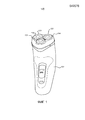
на фиг.1 показан перспективный вид традиционной вращающейся бритвы;figure 1 shows a perspective view of a traditional rotating razor;
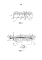
на фиг.2 показан частичный разрез через традиционную вращающуюся бритву вдоль линии A-A на фиг.1;figure 2 shows a partial section through a traditional rotating razor along line A-A in figure 1;
на фиг.3 показан схематичный разрез через часть вращающейся бритвы в соответствии с изобретением;figure 3 shows a schematic section through a part of a rotating razor in accordance with the invention;
на фиг.4 показана конфигурация некоторого количества полос, которые имеются в области управляемого трения вращающейся бритвы в соответствии с изобретением;figure 4 shows the configuration of a number of bands that are in the area of controlled friction of the rotating razor in accordance with the invention;
на фиг.5a и 5b показаны два разных варианта относительно активирующих средств для полос;5a and 5b show two different variants with respect to the activating means for the bands;
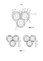
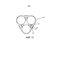
на фиг.6 показан вид спереди контактирующей с кожей поверхности вращающейся бритвы в соответствии с изобретением, включающей в себя множество областей управляемого трения;FIG. 6 is a front view of a rotating razor surface in contact with skin in accordance with the invention, including a plurality of areas of controlled friction; FIG.
на фиг.7 показаны два варианта выборочной активации областей управляемого трения вращающейся бритвы фиг.6, в зависимости от действительного направления движения вращающейся бритвы;FIG. 7 shows two options for selectively activating the areas of controlled friction of the rotating razor of FIG. 6, depending on the actual direction of movement of the rotating razor;
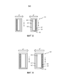
на фиг.8 схематично показана линейная бритва в соответствии с изобретением, содержащая набор лезвий и области управляемого трения, расположенные на каждой стороне набора лезвий, причем показаны два варианта выборочной активации областей управляемого трения, в зависимости от действительного направления движения линейной бритвы;FIG. 8 shows a schematic of a linear razor in accordance with the invention, comprising a set of blades and areas of controlled friction located on each side of a set of blades, with two options for selectively activating areas of controlled friction, depending on the actual direction of movement of the linear razor;
фиг.9 относится к фотоэпилятору в соответствии с изобретением, содержащему источник света и области управляемого трения, расположенные на каждой стороне источника света, причем показаны два варианта выборочной активации областей управляемого трения, в зависимости от действительного направления движения фотоэпилятора; иFig.9 relates to a photoepilator in accordance with the invention, containing a light source and areas of controlled friction, located on each side of the light source, and two options for selectively activating areas of controlled friction, depending on the actual direction of movement of the photoepilator, and
на фиг.10 показан вид спереди контактирующей с кожей поверхности альтернативной вращающейся бритвы в соответствии с изобретением, включающей в себя множество моторизированных роликов.10 shows a front view of an alternative rotary razor surface in contact with skin according to the invention, including a plurality of motorized rollers.
ПОДРОБНОЕ ОПИСАНИЕ ВАРИАНТОВ ОСУЩЕСТВЛЕНИЯ ИЗОБРЕТЕНИЯDETAILED DESCRIPTION OF EMBODIMENTS OF THE INVENTION
На фиг.1 показана традиционная вращающаяся электрическая бритва 100, использующаяся для «сухого» бритья. Бритва 100 содержит основной корпус 101 и три элемента для ухода за кожей или головки 102, смонтированные в неподвижном установочном элементе или лицевой пластине 104. Каждая из головок 102 включает в себя вращающийся режущий элемент (не показан на фиг.1) и внешний колпачок 106, служащий в качестве предохранительного элемента режущего элемента, имеющего множество отверстий 108 для входа волосков, через которые волоски могут входить в колпачок 106 для отрезания режущим элементом. Во время использования бритвы 100, основной корпус 101 удерживается пользователем, и лицевая пластина 104 перемещается по коже пользователя таким образом, что внешние колпачки 106 головок 102 контактируют с кожей, и отрезаемые волоски захватываются отверстиями 108 для входа волосков внешних колпачков 106.Figure 1 shows the traditional rotating
На фиг.2 показан увеличенный разрез через одну из головок 102, взятый по линии A-A на фиг.1. С целью иллюстрации, показан голосок H, выступающий через отверстие 108 для входа волосков внешнего колпачка 106, причем режущий элемент 110 показан перемещающимся в направлении X для отрезания волоска H посредством взаимодействия с отверстием 108 для входа волосков иным традиционным образом. На фиг.2 также показан образ, которым кожа S выступает в отверстия 108 для входа волосков в B, т.е. образ, которым происходит выступание кожи. В этом отношении, лицевая пластина 104 перемещается в направлении M движения относительно кожи S, которое соответствует направлению X движения режущего элемента 110. Выпуклость B, следовательно, толкается к одной стороне отверстия 108 для входа волосков. Однако, следует понимать, что режущий элемент 110 вращается и его локальное направление X движения, следовательно, не всегда соответствует направлению M движения лицевой пластины 104 по коже S. Следует отметить, что, так как головки 102 имеют неизменное положение на лицевой пластине 104, направление M движения лицевой пластины 104 также представляет собой направление движения головок 102 и внешних колпачков 106, которые являются частью головок 102. Более того, направление M движения лицевой пластины 104 соответствует главному направлению движения бритвы 100, в котором предполагается, что пользователь перемещает бритву 100 по коже S.FIG. 2 shows an enlarged section through one of the
Вследствие выпуклости B кожи в отверстия 108 для входа волосков, кожа S может повреждаться вследствие контакта с режущим элементом 110. Это повреждение может быть уменьшено с помощью различных средств, включая увеличение толщины внешнего колпачка 106 и уменьшение ширины отверстий 108 для входа волосков. Однако, такие адаптации оказывают негативное воздействие на близость процесса бритья, которая может достигаться. Изобретение обеспечивает другое решение, что касается принятия мер для осуществления предпочтительного баланса между близостью и раздражением, как будет объяснено позже.Due to the bulge B of the skin in the hair entry holes 108, the skin S may be damaged due to contact with the cutting
На фиг.3 показан схематичный разрез через часть вращающейся бритвы 100A в соответствии с изобретением. Подобные элементы фиг.1 и 2 будут обозначаться подобными ссылочными позициями, несмотря на то, что фиг.1 и 2 относятся к традиционной ситуации, тогда как фиг.3 относится к изобретению.Figure 3 shows a schematic section through a portion of the
В варианте осуществления вращающейся бритвы 100A в соответствии с изобретением, показанном на фиг.3, области 122 управляемого трения расположены на установочном элементе или лицевой пластине 104. В каждой из областей 122 управляемого трения, имеется множество полос 124, причем полосы 124 расположены таким образом, чтобы быть подвижными в их продольном направлении L, причем полосы 124 проходят вдоль друг друга, и причем активирующие средства 126 предусмотрены для активации полос 124 и их побуждения выполнять возвратно-поступательное движение во время использования бритвы 100A. Активирующие средства 126 соединены с источником 128 напряжения. В общем, благодаря расположению полос 124, которые имеются в области 122 управляемого трения, при движении во время использования, трение в зоне взаимодействия с кожей S уменьшается в месте области 122 управляемого трения, и благодаря наличию областей управляемого трения с разным трением, является возможным растягивать кожу S до некоторой степени для уменьшения высоты выпуклости B кожи S, т.е. для уменьшения величины выступания кожи, без непосредственного ухудшения близости процесса бритья каким-либо образом. На фиг.3, вся контактирующую с кожей поверхность вращающейся бритвы 100A в соответствии с изобретением, которая содержит внешнюю поверхность внешних колпачков 106 и основную поверхность полос 124 (т.е. области 122 управляемого трения), обозначена с помощью ссылочной позиции 107.In the embodiment of the
В показанном примере, датчик 130 расположен на лицевой пластине 104 для определения степени выступания кожи. Датчик 130 представляет собой ИК фотодиод, который работает вместе с ИК СИДом 132 для определения выступания кожи S через отверстия 108 для входа волосков во внешнем колпачке 106, что представляет собой пример первого параметра, относящегося к трению, в частности величине трения, между контактирующей с кожей поверхностью 107 и кожей S, в частности параметра, на который влияет указанное трение. Датчик 130 и СИД 132 - оба соединены с контроллером 134, который включает в себя подходящую схему для обработки их сигналов. При использовании, СИД 132 излучает ИК свет, который отражается кожей S. Контроллер 134 предназначен для определения высоты выпуклости B и управления источником 128 напряжения для питания активирующих средств 126 одной или более подходящих областей 122 управляемого трения для активации полос 124 в этих областях 122 управляемого трения, например, когда выпуклость B оказывается выше допустимого максимума. Посредством управления источником 128 напряжения с помощью контроллера 134, второй параметр, связанный со скользящим движением активированных полос 124, управляется в зависимости от первого параметра, т.е. измеренной высоты выпуклости B. В частности, указанный второй параметр представляет собой параметр движения скользящего движения активированных полос 124, например максимальную скорость, частоту или амплитуду скользящего движения. Управление вторым параметром может быть, например, таким, чтобы поддерживать требуемую оптимальную высоту выпуклости B. В настоящем варианте осуществления, измеряется выступание кожи через внешний колпачок 106, но следует понимать, что выступание кожи может измеряться в различных местах, включая в углублении, образованном в лицевой пластине 104, спереди лицевой пластины 104 или между лицевой пластиной 104 и внешним колпачком 106.In the example shown, the
На фиг.4, 5a и 5b показаны дополнительные подробности полос 124, которые имеются в области 122 управляемого трения, и активирующие средства 126 для активации полос 124. Полосы 124 предназначены для выполнения скользящего движения относительно установочного элемента или лицевой пластины 104 и кожи S в продольном направлении L полос 124. Таким образом, скользящее движение является по существу перпендикулярным относительно главного направления M движения бритвы 100A по коже S и выполняется в направлении, соответствующем локальному направлению протяженности контактирующей с кожей поверхности 107, которая, в настоящем случае, является параллельной относительно планарной поверхности полос 124. На фиг.4, главное направление M движения бритвы 100A обозначено с помощью вертикальной стрелки, тогда как скользящее движение полос 124 обозначено горизонтальными стрелками, которые являются двунаправленными для отображения возвратно-поступательное характера движения полос 124. Предположение, лежащее в основе фиг.4, заключается в том, что полосы 124 имеют поперечную ориентацию относительно главного направления M движения, что является оптимальным для получения эффекта уменьшения трения на основе скользящего движения полос 124 относительно лицевой пластины 104 и кожи S в области 122 управляемого трения. С целью полноты освещения темы, следует отметить, что полосы 124 также могут иметь другую ориентацию относительно главного направления M движения для получения эффекта как упомянут, при условии, что ориентация не является точно параллельной относительно главного направления M движения. Однако, в дальнейшем, с целью объяснения изобретения, предполагается поперечная ориентация.4, 5a and 5b show additional details of the
Каждая область 122 управляемого трения вращающейся бритвы 100A в соответствии с изобретением может содержать множество полос 124, как показано на фиг.4, но также является возможным, что одна полоса 124 применяется для каждой области 122 управляемого трения. Полосы 124 могут быть выполнены из любого подходящего материала, например, полимера или нержавеющей стали. В общем, полосы 124 могут размещаться на пластиковом корпусе вращающейся бритвы, корпусе сеточной бритвы или на картридже при лазерном бритье. Активация полос 124 может осуществляться посредством использования технологии электроактивного полимера (EAP). Эта технология использует очень мягкие полимеры, которые являются способными деформироваться в большой степени, т.е. больше 10%. Механически более жесткие электроактивные полимеры включают пьезоэлектрические полимеры (PVDF) и электрострикционные полимеры (PVDF-TrFe-CFe). Указанные электрострикционные полимеры могут прикладывать большее механическое усилие в качестве компенсации более скромных уровней деформации (1-7%), что может быть более подходящим относительно предполагаемого применения в бритве 100A в соответствии с изобретением. В частности, активация возвратно-поступательного движения или вибрации полос 124 может осуществляться посредством чередующихся расширения и сжатия активирующих элементов, содержащих подходящий электроактивный полимер, который является электрически активируемым посредством источника 128 напряжения.Each
Для локального уменьшения трения между кожей S и контактирующей с кожей поверхностью 107 в месте полос 124 в главном направлении M движения вращающейся бритвы 100A, требуется обеспечить то, что действительное скольжение происходит в месте взаимодействия бритвы и кожи. Так как кожа человека является очень гибкой в латеральном направлении, т.е. направлении, перпендикулярном относительно главного направления M движения, амплитуда возвратно-поступательного движения полос 124 должна быть достаточно большой, чтобы преодолевать статическую фазу, в которой кожа S растягивается в латеральном направлении, но действительного скольжения не происходит. Требуемая амплитуда зависит от нескольких факторов, включая коэффициент трения (который зависит от состояния кожи S), ширину полос 124 и количество полос 124. В этом отношении, является предпочтительным использовать полосы 124, имеющие относительно небольшую ширину, и перемещать смежные полосы 124 в противоположных направлениях в плоскости, в которой проходят полосы 124. Например, в случае, когда полосы 124 имеют ширину от около 0,5 до 1 мм, амплитуда возвратно-поступательного движения в 1-2 мм оценивается достаточной для приведения к действительному скольжению в месте взаимодействия с кожей для любых состояний кожи. Частота возвратно-поступательного движения от 0,5 до 1 Гц (квадратная волна) приводила бы к максимальной скорости скользящего движения в 2 мм/с. Предпочтительно, для достижения существенного уменьшения трения, максимальная скорость скользящего движения существенно больше общей скорости вращающейся бритвы 100A в главном направлении движения. Например, для возвратно-поступательного бокового скользящего движения, имеющего синусоидальный профиль скорости, максимальная скорость бокового скользящего движения должна составлять, приблизительно, в 2 раза больше скорости устройства для ухода за кожей для осуществления 50% уменьшения трения между областью управляемого трения и кожей.For local reduction of friction between the skin S and the skin-contacting
Первый пример достижения требуемой активации полос 124, используя электроактивный полимер, показан на фиг.5a. В частности, в соответствии с этим примером, каждая полоса 124 связана с двумя удлиненными активирующими элементами 136, 137 из полимера, причем каждый из активирующих элементов 136, 137 проходит между установочным элементом 104, вблизи соответствующего одного из первого концевого участка 141 и второго концевого участка 142 полосы 124, и центральным участком 143 полосы 124. В этой конфигурации, активирующие элементы 136, 137 активируются поочередно, вызывая возвратно-поступательное движение полосы 124. Например, PVDF-TrFe-CFe полимеры типично расширяются на около 5%, что обеспечивает амплитуду возвратно-поступательного движения в 1 мм для полосы 124 длиной 4 см. Активирующие элементы 136, 137 могут быть незначительно предварительно растянутыми для исключения прогибания.The first example of achieving the desired activation of the
На фиг.5b показана опция для достижения более высоких амплитуд возвратно-поступательного движения полосы 124, которая основана на идее того, что эффективная длина полосы 124 может увеличиваться посредством изменения положения, где активирующие элементы 136, 137 прикрепляются к полосе 124. В соответствии с примером, показанным на фиг.5b, активирующие элементы 136, 137 не сцепляются с полосой 124 в центральном участке. Вместо того, первые концевые участки 144 двух активирующих элементов 136, 137 соединяются, соответственно, с первым концевым участком 145 полосы 124 и вторым концевым участком 146 полосы 124, и вторые концевые участки 147 двух активирующих элементов 136, 137 соединяются с установочным элементом 104 в местах, вблизи, соответственно, второго концевого участка 146 полосы 124 и первого концевого участка 145 полосы 124. Таким образом, активирующие элементы 136, 137 являются, приблизительно, в два раза длиннее, чем в первом примере, показанном на фиг.5a, в результате чего амплитуда возвратно-поступательного движения полосы 124 составляет около 2 мм для полосы 124 длиной 4 см. В любом случае, использование электроактивных полимеров для активации полос 124 не требует существенного дополнительного пространства в лицевой пластине 104, так как толщина активирующих элементов 136, 137 порядка 100 мкм является достаточной.Fig. 5b shows an option for achieving higher amplitudes of the reciprocating movement of the
На фиг.6 показан вид спереди установочного элемента или лицевой пластины 104 вращающейся бритвы 100A в соответствии с изобретением. Помимо трех головок 102, на этом виде можно увидеть множество областей 122 управляемого трения. В частности, в показанном примере, каждая головка 102 окружена четырьмя областями 122 управляемого трения, причем области 122 управляемого трения имеют удлиненную форму и более или менее расположены в соответствии с квадратным охватыванием связанной головки 102. Какая одна из четырех областей 122 управляемого трения активируется в действительной ситуации, зависит от действительного направления M' движения вращающейся бритвы 100A по коже S. Факт заключается в том, что для уменьшения выступания кожи, является желательным иметь область уменьшенного трения на контактирующей с кожей поверхности в заднем положении относительно головки 102, если смотреть в действительном направлении M' движения. Это может быть достигнуто посредством активации полос 124 областей 122 управляемого трения, которые находятся в заднем положении, как упомянуто, во время использования бритвы 100A.Figure 6 shows a front view of the mounting element or the
В ситуации, показанной на левой стороне фиг.7, действительное направление M' движения вращающейся бритвы 100A обозначено с помощью стрелки, указывающей вниз. В этом случае, полосы 124 областей 122 управляемого трения, которые имеются на стороне головок 102, которая представляет собой верхнюю сторону на изображении фиг.7, приводятся в движение в направлении L, поперечном относительно действительного направления M' движения вращающейся бритвы 100A, тогда как полосы 124 других областей 122 управляемого трения поддерживаются в неподвижном состоянии. На фиг.7, активные области 122 управляемого трения обозначены с помощью штриховки.In the situation shown on the left side of FIG. 7, the actual direction M ′ of the movement of the
В ситуации, показанной на правой стороне фиг.7, действительное направление M' движения вращающейся бритвы 100A обозначено с помощью стрелки, указывающей вверх. Следовательно, действительное направление M' движения, как упомянуто, является противоположным относительно действительного направления M' движения, которое является применимым к ситуации, показанной на левой стороне фиг.7. В этом противоположном случае, полосы 124 областей 122 управляемого трения, которые имеются на стороне головок 102, которая представляет собой нижнюю сторону на изображении фиг.7, приводятся в движение в направлении L, поперечном относительно действительного направления M' движения вращающейся бритвы 100A, тогда как полосы 124 других областей 122 управляемого трения поддерживаются в неподвижном состоянии.In the situation shown on the right side of FIG. 7, the actual direction M ′ of the movement of the
Конфигурация, в которой каждый элемент для ухода за кожей или головка 102 окружена четырьмя областями 122 управляемого трения, представляет собой только один пример практических возможностей, существующих в пределах изобретения. Например, также является возможным для областей 122 управляемого трения быть расположенными только на периферии лицевой пластины 104, причем в действительной ситуации активируются только те области 122, которые находятся в заднем положении, если смотреть в действительном направления M' движения вращающейся бритвы 100A.A configuration in which each skin care element or
В варианте осуществления фиг.6, бритва 100A в соответствии с изобретением оснащена сенсорным средством для определения действительного направления M' движения вращающейся бритвы 100A по коже во время использования, которое может быть любого подходящего типа. Действительное направление M' движения представляет собой дополнительный пример первого параметра, относящегося к трению между контактирующей с кожей поверхностью и кожей S, в частности параметра, который влияет на указанное трение, в частности направление указанного трения. Сенсорное средство может представлять собой, например, оптический датчик 138 направления, который расположен в центре лицевой пластины 104 и который функционально соединен с контроллером 134. Во время использования, оптический датчик 138 делает снимки с определенной частотой, например, частотой около 30 Гц, и контроллер 134 вычисляет вектор движения на основании разниц между последовательными снимками. Вместо оптического датчика 138, другой тип датчика может использоваться для измерения действительного направления M' движения и/или скорости бритвы 100A, например, механический датчик скорости или акселерометр. Контроллер 134 использует вектор движения, а также скорость движения вращающейся бритвы 100A относительно кожи, для определения действительного направления M' движения. На основании этого измерения, контроллер 134 является способным определять, какие области 122 управляемого трения находятся в заднем положении относительно головок 102, если смотреть в определенном действительном направлении M' движения, и, таким образом, должны активироваться для осуществления скользящего движения контактирующей с кожей поверхности в местах этих областей 122 управляемого трения, а какие области 122 управляемого трения находятся в других положениях и, таким образом, не должны активироваться. Более того, контроллер 134 является способным задавать значение максимальной скорости возвратно-поступательного движения активированных полос 124, или значение другого параметра возвратно-поступательного движения, например, частоту или амплитуду, или комбинацию параметров возвратно-поступательного движения. Таким образом, как объяснено выше, трение в задних положениях контактирующей с кожей поверхности уменьшено, на основании чего является возможным иметь улучшенный захват на коже S, уменьшить выступание кожи и/или поддерживать степень выступания кожи на оптимальном значении.In the embodiment of FIG. 6, the
Изобретение является применимым к многим другим устройствам для ухода за кожей помимо вращающейся бритвы. Фиг.8 относится к линейной бритве 200 в соответствии с изобретением, содержащей лицевую пластину 104, в которой расположены как набор лезвий 202, так и области 122 управляемого трения. Области 122 управляемого трения расположены на каждой стороне набора лезвий 202 и могут содержать одну или более подвижно расположенных полос 124, как объяснено выше. Линейная бритва 200 имеет сенсорное средство по меньшей мере для определения действительного направления M' движения бритвы 200 относительно кожи во время использования, которое может включать в себя датчик, аналогичный оптическому датчику 138 направления бритвы 100A фиг.6.The invention is applicable to many other skin care devices besides a rotating razor. FIG. 8 relates to a
В ситуации, показанной на левой стороне фиг.8, действительное направление M' движения лицевой пластины 104 обозначено с помощью стрелки, указывающей вправо. В этом случае, полосы 124 областей 122 управляемого трения, которые имеются на стороне набора лезвий 202, которая представляет собой левую сторону на изображении фиг.8, приводятся в скользящее движение в направлении L, поперечном относительно действительного направления M' движения линейной бритвы 200, тогда как полосы 124 других областей 122 управляемого трения поддерживаются в неподвижном состоянии. На фиг.8, активные области 122 управляемого трения обозначены с помощью штриховки.In the situation shown on the left side of FIG. 8, the actual direction M ′ of the movement of the
В ситуации, показанной на правой стороне фиг.8, действительное направление M' движения линейной бритвы 200 обозначено с помощью стрелки, указывающей влево. Следовательно, действительное направление M' движения, как упомянуто, является противоположным относительно действительного направления M' движения, которое является применимым к ситуации, показанной на левой стороне фиг.8. В этом обратном случае, полосы 124 областей 122 управляемого трения, которые имеются на стороне набора лезвий 202, которая представляет собой правую сторону на изображении фиг.8, приводятся в скользящее движение в направлении L, поперечном относительно действительного направления M' движения линейной бритвы 200, тогда как полосы 124 других областей 122 управляемого трения поддерживаются в неподвижном состоянии.In the situation shown on the right side of FIG. 8, the actual direction M ′ of the movement of the
Под воздействием активных областей 122 управляемого трения, является возможным получить эффект растягивания кожи во время использования линейной бритвы 200, в результате чего раздражение кожи может быть уменьшено.Under the influence of the
Фиг.9 относится к фотоэпилятору 300 в соответствии с изобретением, содержащему лицевую пластину 104, в которой расположены как источник 302 света, так и области 122 управляемого трения. Области 122 управляемого трения расположены на каждой стороне источника 302 света и могут содержать одну или более подвижно расположенных полос 124, как объяснено выше. Фотоэпилятор 300 имеет сенсорное средство по меньшей мере для определения действительного направления M' движения фотоэпилятора 300 относительно кожи во время использования, которое может включать в себя датчик, аналогичный оптическому датчику 138 направления бритвы 100A фиг.6.FIG. 9 relates to a
В ситуации, показанной на левой стороне фиг.9, действительное направление M' движения фотоэпилятора 300 обозначено с помощью стрелки, указывающей вправо. В этом случае, полосы 124 областей 122 управляемого трения, которые имеются на стороне источника 302 света, которая представляет собой левую сторону на изображении фиг.9, приводятся в скользящее движение в направлении L, поперечном относительно действительного направления M' движения фотоэпилятора 300, тогда как полосы 124 других областей 122 управляемого трения поддерживаются в неподвижном состоянии. На фиг.9, активные области 122 управляемого трения обозначены с помощью штриховки.In the situation shown on the left side of FIG. 9, the actual direction M ′ of the movement of the
В ситуации, показанной на правой стороне фиг.9, действительное направление M' движения фотоэпилятора 300 обозначено с помощью стрелки, указывающей влево. Следовательно, действительное направление M' движения, как упомянуто, является противоположным относительно действительного направления M' движения, которое является применимым к ситуации, показанной на левой стороне фиг.9. В этом обратном случае, полосы 124 областей 122 управляемого трения, которые имеются на стороне источника 302 света, которая представляет собой правую сторону на изображении фиг.9, приводятся в скользящее движение в направлении L, поперечном относительно действительного направления M' движения фотоэпилятора 300, тогда как полосы 124 других областей 122 управляемого трения поддерживаются в неподвижном состоянии.In the situation shown on the right side of FIG. 9, the actual direction M ′ of the movement of the
Под воздействием активных областей 122 управляемого трения, является возможным получить эффект растягивания кожи во время использования фотоэпилятора 300, что может быть предпочтительным для работы фотоэпилятора 300.Under the influence of the
На фиг.10 показан вид спереди лицевой пластины 104 альтернативной вращающейся бритвы 100B в соответствии с изобретением для иллюстрации варианта, отличного от варианта, имеющего возвратно-поступательные полосы 124 в областях 122 управляемого трения. В частности, в соответствии с альтернативным вариантом, моторизированные ролики 125 используются вместо удлиненных полос 124. Во время работы вращающейся бритвы 100B, ролики 125, предпочтительно, приводятся в действие таким образом, чтобы выполнять непрерывное вращение вокруг их продольных осей для осуществления скользящего движения непрерывного характера, что не отменяет тот факт, что также является возможным иметь возвратно-качательное вращение роликов 125, если таковое требуется, для осуществления скользящего движения возвратно-качательного характера, подобного скользящему движению, связанному с полосами 124. Бритва 100B имеет сенсорное средство по меньшей мере для определения действительного направления движения бритвы 100B относительно кожи во время использования, которое может включать в себя датчик, аналогичный оптическому датчику 138 направления бритвы 100A фиг.6.Figure 10 shows a front view of the
В случае применения роликов 125, как описано выше, является предпочтительным иметь группы из двух перпендикулярных роликов 125, таким образом является возможным всегда иметь ролик 125, направление вращения которого отклоняется от действительного направления движения вращающейся бритвы 100B, и активировать ролик 125, направление вращения которого отклоняется от действительного направления движения в большей степени, для получения оптимального эффекта локального уменьшения трения. На фиг.10 показаны только три группы перпендикулярных роликов 125, но следует понимать, что является возможным иметь больше групп роликов 125, причем является предпочтительным, что ролики 125 располагаются в стратегических положениях касательно осуществления заднего положения роликов 125 относительно различных головок 102, расположенных на лицевой пластине 104, для некоторого количества разных направлений движения вращающейся бритвы 100B. В варианте осуществления вращающейся бритвы 100B, скользящее движение каждого ролика 125 выполняется в направлении, которое является тангенциальным относительно внешней поверхности ролика 125 в месте контакта, где внешняя поверхность ролика 125 находится в контакте с кожей. В этом месте контакта, внешняя поверхность ролика 125 образует часть контактирующей с кожей поверхности вращающейся бритвы 100B. Так как указанное тангенциальное направление соответствует локальному направлению протяженности внешней поверхности ролика в указанном месте контакта, также в случае вращающейся бритвы 100B направление скользящего движения соответствует локальному направлению протяженности контактирующей с кожей поверхности.When using
В вариантах осуществления изобретения, описанных здесь ранее, разные примеры первых параметров, относящихся к трению между контактирующей с кожей поверхностью 107 и кожей S, измеряются для управления боковым скользящим движением области 122 управляемого трения. Указанные примеры включают параметры, на которые влияет трение, например, величина выступания кожи в отверстии 108 для входа волосков в варианте осуществления фиг.3, и параметры, которые влияют на трение, например действительное направление M' движения в варианте осуществления фиг.6 и 7. Следует отметить, что, в соответствии с изобретением, боковое скользящее движение также может управляться в зависимости от комбинации этих первых параметров или других примеров таких первых параметров. Другие примеры таких первых параметров включают нормальное усилие, прикладываемое кожей к контактирующей с кожей поверхности 107, или уровень влажности в месте взаимодействия между контактирующей с кожей поверхностью 107 и кожей, в качестве примеров первых параметров, которые влияют на трение между контактирующей с кожей поверхностью 107 и кожей, и температуру кожи ниже контактирующей с кожей поверхности 107, в качестве примера первого параметра, на который влияет трение между контактирующей с кожей поверхностью 107 и кожей.In embodiments of the invention described hereinbefore, various examples of the first parameters related to friction between the skin-contacting
В случае измерения нормального усилия, скорость бокового скользящего движения может увеличиваться в случае увеличения измеренного нормального усилия, что будет уменьшать коэффициент трения и привет к стабильной силе трения. Датчик нормального усилия может встраиваться в рукоятку или в обрабатывающую головку устройства для ухода за кожей и может представлять собой датчик, работающий в соответствии с любым общеизвестным принципом измерения усилия, например, пьезорезистивным, индуктивным, оптическим и пьезоэлектрическим принципами.In the case of measuring the normal force, the lateral sliding movement may increase in case of an increase in the measured normal force, which will reduce the coefficient of friction and hi to a stable friction force. A normal force sensor can be integrated into the handle or into the processing head of a skin care device and can be a sensor that works according to any well-known principle of force measurement, for example, piezoresistive, inductive, optical and piezoelectric principles.
В случае измерения уровня влажности в месте взаимодействия между контактирующей с кожей поверхностью 107 и кожей, скорость бокового скользящего движения может увеличиваться в случае увеличения измеренного уровня влажности, так как, обычно, влажная кожа приводит к большему трению, чем сухая кожа.In the case of measuring the level of humidity at the site of interaction between the skin-contacting
В случае измерения температуры кожи ниже контактирующей с кожей поверхности 107, скорость бокового скользящего движения может увеличиваться в случае, если измеренная температура, или увеличение температуры в течение определенного периода времени, кожи в контакте с устройством для ухода за кожей выше предварительно заданного порогового значения. В таком случае, в результате увеличенной скорости бокового скользящего движения, трение между кожей и контактирующей с кожей поверхностью и сопутствующее рассеивание тепла будут уменьшаться, вызывая уменьшение температуры кожи. Датчик может представлять собой термопару, терморезистор или другой датчик температуры.In the case of measuring the skin temperature below the skin-contacting
Для специалиста в данной области будет очевидным, что объем изобретения не ограничен на примерах, рассмотренных выше, но что возможны несколько его изменений и модификаций, не отклоняясь от объема изобретения, как определено в прилагаемой формуле изобретения. Хотя изобретение было подробно проиллюстрировано и описано на фигурах и описании, такую иллюстрацию и описание следует рассматривать только иллюстративными или примерными, а не ограничивающими. Изобретение не ограничено на раскрытых вариантах осуществления.It will be obvious to a person skilled in the art that the scope of the invention is not limited to the examples discussed above, but that several changes and modifications are possible without deviating from the scope of the invention as defined in the appended claims. Although the invention has been illustrated and described in detail in the figures and description, such illustration and description should be considered only illustrative or exemplary and not restrictive. The invention is not limited to the disclosed embodiments.
Изменения в раскрытых вариантах осуществления могут быть понятыми и осуществлены специалистом в данной области при осуществлении заявленного изобретения, из изучения фигур, описания и прилагаемой формулы изобретения. В формуле изобретения, слово «содержащий» не исключает другие этапы или элементы, и единственное число не исключает множество. Простой факт, что определенные меры изложены во взаимно разных зависимых пунктах формулы изобретения, не обозначает, что комбинация этих мер не может использоваться в качестве преимущества. Любые ссылочные позиции в формуле изобретения не следует рассматривать как ограничение объема изобретения.Changes in the disclosed embodiments can be understood and made by a person skilled in the art in practicing the claimed invention, from studying the figures, the description and the appended claims. In the claims, the word "comprising" does not exclude other steps or elements, and the singular does not exclude a plurality. The mere fact that certain measures are set forth in mutually different dependent claims does not mean that a combination of these measures cannot be used as an advantage. Any reference numbers in the claims should not be construed as limiting the scope of the invention.
Обеспечение скользящего движения в области 122 управляемого трения, которая имеется в соответствующем месте на устройстве 100A, 100B, 200, 300 для ухода за кожей, является важным признаком изобретения. Этот признак может осуществляться посредством применения одной или более подвижно расположенных полос 124 в области 122 управляемого трения, или одного или более роликов 125, которые являются вращаемыми вокруг своих продольных осей, как объяснено выше, но также является возможным применять любой другой подходящий тип средства.Providing a sliding movement in the
Claims (19)
Applications Claiming Priority (3)
| Application Number | Priority Date | Filing Date | Title |
|---|---|---|---|
| EP14197462 | 2014-12-11 | ||
| EP14197462.6 | 2014-12-11 | ||
| PCT/EP2015/078471 WO2016091706A1 (en) | 2014-12-11 | 2015-12-03 | Skin treatment device |
Publications (3)
| Publication Number | Publication Date |
|---|---|
| RU2017124237A RU2017124237A (en) | 2019-01-11 |
| RU2017124237A3 RU2017124237A3 (en) | 2019-04-16 |
| RU2692271C2 true RU2692271C2 (en) | 2019-06-24 |
Family
ID=52133842
Family Applications (1)
| Application Number | Title | Priority Date | Filing Date |
|---|---|---|---|
| RU2017124237A RU2692271C2 (en) | 2014-12-11 | 2015-12-03 | Skin care device |
Country Status (7)
| Country | Link |
|---|---|
| US (1) | US10932541B2 (en) |
| EP (1) | EP3230020B1 (en) |
| JP (1) | JP6588550B2 (en) |
| CN (1) | CN106998869B (en) |
| BR (1) | BR112017012043B1 (en) |
| RU (1) | RU2692271C2 (en) |
| WO (1) | WO2016091706A1 (en) |
Families Citing this family (14)
| Publication number | Priority date | Publication date | Assignee | Title |
|---|---|---|---|---|
| BR112017005895B1 (en) * | 2014-09-26 | 2021-02-09 | Koninklijke Philips N.V | device for shaving or hair removal from the skin |
| US11097436B2 (en) | 2016-06-20 | 2021-08-24 | Koninklijke Philips N.V. | Friction control device and method |
| KR102628092B1 (en) * | 2016-11-07 | 2024-01-23 | 엘지전자 주식회사 | Skin care device |
| US20190224870A1 (en) * | 2018-01-19 | 2019-07-25 | The Gillette Company Llc | Shaving appliance including a notification cirucit for communicating shave stroke direction information |
| US11117276B2 (en) * | 2018-01-19 | 2021-09-14 | The Gillette Company Llc | Method for generating user feedback information from a shave event |
| US10960560B2 (en) * | 2018-01-19 | 2021-03-30 | The Gillette Company Llc | Method for generating user feedback information from a shave event |
| EP3546151A1 (en) | 2018-03-27 | 2019-10-02 | Braun GmbH | Personal care device |
| EP3546149B1 (en) | 2018-03-27 | 2021-05-12 | Braun GmbH | Hair removal device |
| EP3769644A1 (en) * | 2019-07-25 | 2021-01-27 | Koninklijke Philips N.V. | Skin treatment device and method of controlling a skin treatment device |
| US11697215B2 (en) * | 2019-09-19 | 2023-07-11 | Carefusion 2200, Inc. | Surgical hair clippers and vacuum apparatuses including sensing and feedback devices |
| JP7296299B2 (en) * | 2019-10-28 | 2023-06-22 | マクセルイズミ株式会社 | rotary electric razor |
| CN112873286A (en) * | 2021-01-11 | 2021-06-01 | 深圳素士科技股份有限公司 | Electric shaver |
| KR20240035934A (en) * | 2021-07-27 | 2024-03-19 | 코닌클리케 필립스 엔.브이. | Shaving unit and electric razor including same |
| EP4147833A1 (en) * | 2021-09-09 | 2023-03-15 | Koninklijke Philips N.V. | Shaving unit and electric shaver comprising the same |
Citations (6)
| Publication number | Priority date | Publication date | Assignee | Title |
|---|---|---|---|---|
| CH355713A (en) * | 1957-03-30 | 1961-07-15 | Miller Hermann | Dry razor |
| FR2749793A1 (en) * | 1996-06-12 | 1997-12-19 | Philips Electronics Nv | Electric razor with friction sensor |
| FR2810516A1 (en) * | 2000-06-27 | 2001-12-28 | Seb Sa | Depilatory appliance has means to reduce pain consisting of an element located adjacent to the hair removal head and made to oscillate transversely by a separate motor acting through a cam and slot |
| WO2005056251A1 (en) * | 2003-12-10 | 2005-06-23 | Koninklijke Philips Electronics N.V. | Shaving head with skin stretching member |
| EP1764010A1 (en) * | 2005-09-19 | 2007-03-21 | Braun GmbH | Skin peeling device,method for manufacturing such a device and use of such a device in a hand held electrical appliance for personal care |
| WO2013140309A1 (en) * | 2012-03-22 | 2013-09-26 | Koninklijke Philips N.V. | Shaver having adaptive surface |
Family Cites Families (11)
| Publication number | Priority date | Publication date | Assignee | Title |
|---|---|---|---|---|
| JP3721629B2 (en) * | 1995-02-23 | 2005-11-30 | 松下電工株式会社 | Electric razor |
| JP2003181165A (en) | 2001-12-18 | 2003-07-02 | Kao Corp | Vibration razor |
| US20050235495A1 (en) * | 2004-04-22 | 2005-10-27 | Aviza Gregory D | Shaving systems with exfoliation |
| DE102005045713A1 (en) * | 2005-09-24 | 2007-03-29 | Braun Gmbh | Electric hair removal device |
| EP2101863A2 (en) * | 2006-11-24 | 2009-09-23 | Koninklijke Philips Electronics N.V. | Iontophoretic device |
| EP2250431B1 (en) | 2008-02-05 | 2015-10-28 | Philips Intellectual Property & Standards GmbH | Lighting device with reflective electroactive polymer actuator |
| DE102008041682A1 (en) * | 2008-08-29 | 2010-03-04 | Robert Bosch Gmbh | Electric hand tool |
| CN102137602B (en) * | 2008-09-01 | 2015-01-14 | 皇家飞利浦电子股份有限公司 | Tilting prevention for depilating devices |
| DE102009010603A1 (en) | 2009-02-25 | 2010-05-12 | Siemens Medical Instruments Pte. Ltd. | Hearing aid i.e. completely-into-the-canal hearing aid, has actuator that is controllable based on characteristic of acoustic environment of hearing aid, where actuator and sensor are made of electro-active polymer |
| JP2014030476A (en) * | 2012-08-01 | 2014-02-20 | Panasonic Corp | Razor device and head housing of razor device |
| US10315320B2 (en) * | 2012-12-13 | 2019-06-11 | Panasonic Intellectual Property Management Co., Ltd. | Electric shaver |
-
2015
- 2015-12-03 WO PCT/EP2015/078471 patent/WO2016091706A1/en active Application Filing
- 2015-12-03 CN CN201580067210.5A patent/CN106998869B/en active Active
- 2015-12-03 RU RU2017124237A patent/RU2692271C2/en active
- 2015-12-03 EP EP15804486.7A patent/EP3230020B1/en active Active
- 2015-12-03 US US15/532,569 patent/US10932541B2/en active Active
- 2015-12-03 JP JP2017530284A patent/JP6588550B2/en active Active
- 2015-12-03 BR BR112017012043-7A patent/BR112017012043B1/en not_active IP Right Cessation
Patent Citations (6)
| Publication number | Priority date | Publication date | Assignee | Title |
|---|---|---|---|---|
| CH355713A (en) * | 1957-03-30 | 1961-07-15 | Miller Hermann | Dry razor |
| FR2749793A1 (en) * | 1996-06-12 | 1997-12-19 | Philips Electronics Nv | Electric razor with friction sensor |
| FR2810516A1 (en) * | 2000-06-27 | 2001-12-28 | Seb Sa | Depilatory appliance has means to reduce pain consisting of an element located adjacent to the hair removal head and made to oscillate transversely by a separate motor acting through a cam and slot |
| WO2005056251A1 (en) * | 2003-12-10 | 2005-06-23 | Koninklijke Philips Electronics N.V. | Shaving head with skin stretching member |
| EP1764010A1 (en) * | 2005-09-19 | 2007-03-21 | Braun GmbH | Skin peeling device,method for manufacturing such a device and use of such a device in a hand held electrical appliance for personal care |
| WO2013140309A1 (en) * | 2012-03-22 | 2013-09-26 | Koninklijke Philips N.V. | Shaver having adaptive surface |
Also Published As
| Publication number | Publication date |
|---|---|
| BR112017012043A2 (en) | 2018-01-16 |
| WO2016091706A1 (en) | 2016-06-16 |
| JP6588550B2 (en) | 2019-10-09 |
| RU2017124237A3 (en) | 2019-04-16 |
| RU2017124237A (en) | 2019-01-11 |
| US20170325566A1 (en) | 2017-11-16 |
| EP3230020A1 (en) | 2017-10-18 |
| EP3230020B1 (en) | 2019-07-10 |
| CN106998869B (en) | 2020-06-26 |
| US10932541B2 (en) | 2021-03-02 |
| JP2017536913A (en) | 2017-12-14 |
| BR112017012043B1 (en) | 2021-06-08 |
| CN106998869A (en) | 2017-08-01 |
Similar Documents
| Publication | Publication Date | Title |
|---|---|---|
| RU2692271C2 (en) | Skin care device | |
| RU2752387C2 (en) | System and method for processing human body part | |
| EP3065920B2 (en) | A system for treating a part of a body | |
| EP3082576B1 (en) | Method for treating the skin and device | |
| JP6506261B2 (en) | Device and system for treating hair and / or skin | |
| JP2016534805A (en) | System and method for treating a body part | |
| ES2702037T3 (en) | Shaver that has a mating surface with adaptive skin | |
| CN105705104A (en) | Hand held dermaplaning device and dermaplaning process | |
| KR20080088598A (en) | Device for superficial abrasive treatment of the skin | |
| RU2017114354A (en) | HAIR Razor | |
| US20170334080A1 (en) | Elevated back shaver | |
| US9937629B1 (en) | Two-point discrimination safety razor assembly | |
| US11865358B2 (en) | Skin treatment device | |
| US10500744B1 (en) | Safety razor with plurality of comb and integrated blade groups | |
| US11104018B2 (en) | Safety razor with comb and blade | |
| JP4607946B2 (en) | Apparatus and method for acoustic / mechanical treatment of early stage acne | |
| US20170119618A1 (en) | Lower eyelid treatment | |
| JP2017501825A (en) | Shear-induced skin injection | |
| US20210362364A1 (en) | Safety razor with comb and blade | |
| EP0761393B1 (en) | Device for conditioning hairy skin before shaving | |
| WO2016050620A1 (en) | Skin cleaning device | |
| JP2023522019A (en) | skin treatment system |