RU2681309C2 - Light device and luminaire - Google Patents
Light device and luminaire Download PDFInfo
- Publication number
- RU2681309C2 RU2681309C2 RU2016145053A RU2016145053A RU2681309C2 RU 2681309 C2 RU2681309 C2 RU 2681309C2 RU 2016145053 A RU2016145053 A RU 2016145053A RU 2016145053 A RU2016145053 A RU 2016145053A RU 2681309 C2 RU2681309 C2 RU 2681309C2
- Authority
- RU
- Russia
- Prior art keywords
- light
- lighting device
- annular
- onion
- solid
- Prior art date
Links
Images
Classifications
-
- F—MECHANICAL ENGINEERING; LIGHTING; HEATING; WEAPONS; BLASTING
- F21—LIGHTING
- F21K—NON-ELECTRIC LIGHT SOURCES USING LUMINESCENCE; LIGHT SOURCES USING ELECTROCHEMILUMINESCENCE; LIGHT SOURCES USING CHARGES OF COMBUSTIBLE MATERIAL; LIGHT SOURCES USING SEMICONDUCTOR DEVICES AS LIGHT-GENERATING ELEMENTS; LIGHT SOURCES NOT OTHERWISE PROVIDED FOR
- F21K9/00—Light sources using semiconductor devices as light-generating elements, e.g. using light-emitting diodes [LED] or lasers
- F21K9/60—Optical arrangements integrated in the light source, e.g. for improving the colour rendering index or the light extraction
- F21K9/61—Optical arrangements integrated in the light source, e.g. for improving the colour rendering index or the light extraction using light guides
-
- F—MECHANICAL ENGINEERING; LIGHTING; HEATING; WEAPONS; BLASTING
- F21—LIGHTING
- F21V—FUNCTIONAL FEATURES OR DETAILS OF LIGHTING DEVICES OR SYSTEMS THEREOF; STRUCTURAL COMBINATIONS OF LIGHTING DEVICES WITH OTHER ARTICLES, NOT OTHERWISE PROVIDED FOR
- F21V7/00—Reflectors for light sources
- F21V7/22—Reflectors for light sources characterised by materials, surface treatments or coatings, e.g. dichroic reflectors
-
- F—MECHANICAL ENGINEERING; LIGHTING; HEATING; WEAPONS; BLASTING
- F21—LIGHTING
- F21K—NON-ELECTRIC LIGHT SOURCES USING LUMINESCENCE; LIGHT SOURCES USING ELECTROCHEMILUMINESCENCE; LIGHT SOURCES USING CHARGES OF COMBUSTIBLE MATERIAL; LIGHT SOURCES USING SEMICONDUCTOR DEVICES AS LIGHT-GENERATING ELEMENTS; LIGHT SOURCES NOT OTHERWISE PROVIDED FOR
- F21K9/00—Light sources using semiconductor devices as light-generating elements, e.g. using light-emitting diodes [LED] or lasers
- F21K9/20—Light sources comprising attachment means
- F21K9/23—Retrofit light sources for lighting devices with a single fitting for each light source, e.g. for substitution of incandescent lamps with bayonet or threaded fittings
- F21K9/232—Retrofit light sources for lighting devices with a single fitting for each light source, e.g. for substitution of incandescent lamps with bayonet or threaded fittings specially adapted for generating an essentially omnidirectional light distribution, e.g. with a glass bulb
-
- F—MECHANICAL ENGINEERING; LIGHTING; HEATING; WEAPONS; BLASTING
- F21—LIGHTING
- F21K—NON-ELECTRIC LIGHT SOURCES USING LUMINESCENCE; LIGHT SOURCES USING ELECTROCHEMILUMINESCENCE; LIGHT SOURCES USING CHARGES OF COMBUSTIBLE MATERIAL; LIGHT SOURCES USING SEMICONDUCTOR DEVICES AS LIGHT-GENERATING ELEMENTS; LIGHT SOURCES NOT OTHERWISE PROVIDED FOR
- F21K99/00—Subject matter not provided for in other groups of this subclass
-
- F—MECHANICAL ENGINEERING; LIGHTING; HEATING; WEAPONS; BLASTING
- F21—LIGHTING
- F21V—FUNCTIONAL FEATURES OR DETAILS OF LIGHTING DEVICES OR SYSTEMS THEREOF; STRUCTURAL COMBINATIONS OF LIGHTING DEVICES WITH OTHER ARTICLES, NOT OTHERWISE PROVIDED FOR
- F21V29/00—Protecting lighting devices from thermal damage; Cooling or heating arrangements specially adapted for lighting devices or systems
- F21V29/50—Cooling arrangements
- F21V29/70—Cooling arrangements characterised by passive heat-dissipating elements, e.g. heat-sinks
- F21V29/74—Cooling arrangements characterised by passive heat-dissipating elements, e.g. heat-sinks with fins or blades
- F21V29/77—Cooling arrangements characterised by passive heat-dissipating elements, e.g. heat-sinks with fins or blades with essentially identical diverging planar fins or blades, e.g. with fan-like or star-like cross-section
- F21V29/773—Cooling arrangements characterised by passive heat-dissipating elements, e.g. heat-sinks with fins or blades with essentially identical diverging planar fins or blades, e.g. with fan-like or star-like cross-section the planes containing the fins or blades having the direction of the light emitting axis
-
- F—MECHANICAL ENGINEERING; LIGHTING; HEATING; WEAPONS; BLASTING
- F21—LIGHTING
- F21V—FUNCTIONAL FEATURES OR DETAILS OF LIGHTING DEVICES OR SYSTEMS THEREOF; STRUCTURAL COMBINATIONS OF LIGHTING DEVICES WITH OTHER ARTICLES, NOT OTHERWISE PROVIDED FOR
- F21V3/00—Globes; Bowls; Cover glasses
- F21V3/02—Globes; Bowls; Cover glasses characterised by the shape
-
- F—MECHANICAL ENGINEERING; LIGHTING; HEATING; WEAPONS; BLASTING
- F21—LIGHTING
- F21V—FUNCTIONAL FEATURES OR DETAILS OF LIGHTING DEVICES OR SYSTEMS THEREOF; STRUCTURAL COMBINATIONS OF LIGHTING DEVICES WITH OTHER ARTICLES, NOT OTHERWISE PROVIDED FOR
- F21V3/00—Globes; Bowls; Cover glasses
- F21V3/04—Globes; Bowls; Cover glasses characterised by materials, surface treatments or coatings
- F21V3/06—Globes; Bowls; Cover glasses characterised by materials, surface treatments or coatings characterised by the material
- F21V3/062—Globes; Bowls; Cover glasses characterised by materials, surface treatments or coatings characterised by the material the material being plastics
- F21V3/0625—Globes; Bowls; Cover glasses characterised by materials, surface treatments or coatings characterised by the material the material being plastics the material diffusing light, e.g. translucent plastics
-
- F—MECHANICAL ENGINEERING; LIGHTING; HEATING; WEAPONS; BLASTING
- F21—LIGHTING
- F21V—FUNCTIONAL FEATURES OR DETAILS OF LIGHTING DEVICES OR SYSTEMS THEREOF; STRUCTURAL COMBINATIONS OF LIGHTING DEVICES WITH OTHER ARTICLES, NOT OTHERWISE PROVIDED FOR
- F21V7/00—Reflectors for light sources
- F21V7/22—Reflectors for light sources characterised by materials, surface treatments or coatings, e.g. dichroic reflectors
- F21V7/24—Reflectors for light sources characterised by materials, surface treatments or coatings, e.g. dichroic reflectors characterised by the material
-
- F—MECHANICAL ENGINEERING; LIGHTING; HEATING; WEAPONS; BLASTING
- F21—LIGHTING
- F21V—FUNCTIONAL FEATURES OR DETAILS OF LIGHTING DEVICES OR SYSTEMS THEREOF; STRUCTURAL COMBINATIONS OF LIGHTING DEVICES WITH OTHER ARTICLES, NOT OTHERWISE PROVIDED FOR
- F21V7/00—Reflectors for light sources
- F21V7/22—Reflectors for light sources characterised by materials, surface treatments or coatings, e.g. dichroic reflectors
- F21V7/28—Reflectors for light sources characterised by materials, surface treatments or coatings, e.g. dichroic reflectors characterised by coatings
-
- F—MECHANICAL ENGINEERING; LIGHTING; HEATING; WEAPONS; BLASTING
- F21—LIGHTING
- F21V—FUNCTIONAL FEATURES OR DETAILS OF LIGHTING DEVICES OR SYSTEMS THEREOF; STRUCTURAL COMBINATIONS OF LIGHTING DEVICES WITH OTHER ARTICLES, NOT OTHERWISE PROVIDED FOR
- F21V3/00—Globes; Bowls; Cover glasses
- F21V3/04—Globes; Bowls; Cover glasses characterised by materials, surface treatments or coatings
- F21V3/06—Globes; Bowls; Cover glasses characterised by materials, surface treatments or coatings characterised by the material
- F21V3/061—Globes; Bowls; Cover glasses characterised by materials, surface treatments or coatings characterised by the material the material being glass
- F21V3/0615—Globes; Bowls; Cover glasses characterised by materials, surface treatments or coatings characterised by the material the material being glass the material diffusing light, e.g. translucent glass
-
- F—MECHANICAL ENGINEERING; LIGHTING; HEATING; WEAPONS; BLASTING
- F21—LIGHTING
- F21V—FUNCTIONAL FEATURES OR DETAILS OF LIGHTING DEVICES OR SYSTEMS THEREOF; STRUCTURAL COMBINATIONS OF LIGHTING DEVICES WITH OTHER ARTICLES, NOT OTHERWISE PROVIDED FOR
- F21V3/00—Globes; Bowls; Cover glasses
- F21V3/04—Globes; Bowls; Cover glasses characterised by materials, surface treatments or coatings
- F21V3/06—Globes; Bowls; Cover glasses characterised by materials, surface treatments or coatings characterised by the material
- F21V3/062—Globes; Bowls; Cover glasses characterised by materials, surface treatments or coatings characterised by the material the material being plastics
-
- F—MECHANICAL ENGINEERING; LIGHTING; HEATING; WEAPONS; BLASTING
- F21—LIGHTING
- F21Y—INDEXING SCHEME ASSOCIATED WITH SUBCLASSES F21K, F21L, F21S and F21V, RELATING TO THE FORM OR THE KIND OF THE LIGHT SOURCES OR OF THE COLOUR OF THE LIGHT EMITTED
- F21Y2103/00—Elongate light sources, e.g. fluorescent tubes
- F21Y2103/30—Elongate light sources, e.g. fluorescent tubes curved
- F21Y2103/33—Elongate light sources, e.g. fluorescent tubes curved annular
-
- F—MECHANICAL ENGINEERING; LIGHTING; HEATING; WEAPONS; BLASTING
- F21—LIGHTING
- F21Y—INDEXING SCHEME ASSOCIATED WITH SUBCLASSES F21K, F21L, F21S and F21V, RELATING TO THE FORM OR THE KIND OF THE LIGHT SOURCES OR OF THE COLOUR OF THE LIGHT EMITTED
- F21Y2113/00—Combination of light sources
- F21Y2113/10—Combination of light sources of different colours
- F21Y2113/13—Combination of light sources of different colours comprising an assembly of point-like light sources
-
- F—MECHANICAL ENGINEERING; LIGHTING; HEATING; WEAPONS; BLASTING
- F21—LIGHTING
- F21Y—INDEXING SCHEME ASSOCIATED WITH SUBCLASSES F21K, F21L, F21S and F21V, RELATING TO THE FORM OR THE KIND OF THE LIGHT SOURCES OR OF THE COLOUR OF THE LIGHT EMITTED
- F21Y2115/00—Light-generating elements of semiconductor light sources
- F21Y2115/10—Light-emitting diodes [LED]
Abstract
Description
Настоящее изобретение относится к световому устройству, содержащему теплоотвод, имеющий участок кольцевой поверхности, ограничивающий центральное отверстие, причем упомянутый участок кольцевой поверхности несет на себе множество твердотельных световых элементов, а также взаимодействующий с этим теплоотводом луковицеобразный элемент.The present invention relates to a lighting device comprising a heat sink having a portion of an annular surface defining a central hole, said portion of the annular surface bearing a plurality of solid-state light elements, as well as an onion-like element interacting with this heat sink.
Настоящее изобретение, далее, относится к светильнику, содержащему такое световое устройство.The present invention further relates to a luminaire comprising such a lighting device.
УРОВЕНЬ ТЕХНИКИBACKGROUND
При постоянно растущем населении становится все труднее удовлетворять мировые потребности в энергии и одновременно контролировать выбросы углекислого газа, чтобы удерживать в рамках выбросы "парниковых газов", которые считаются причиной явления глобального потепления. Эти проблемы стали толчком к более эффективному использованию электричества в попытке уменьшить потребление энергии.With an ever-growing population, it is becoming increasingly difficult to meet global energy needs and at the same time control carbon dioxide emissions in order to keep the greenhouse gas emissions considered to be the cause of global warming. These problems triggered a more efficient use of electricity in an attempt to reduce energy consumption.
Одной из таких областей особого внимания являются приложения, связанные с освещением как бытового, так и коммерческого окружения. Существует явная тенденция к замене традиционных энергетически относительно неэффективных электрических лампочек, таких как лампочки накаливания или люминесцентные лампочки на более энергоэффективные заменители. Действительно, многими законодательствами производство и розничная продажа электрических лампочек накаливания были поставлены вне закона, тем самым заставляя потребителей, например, при замене ламп накаливания покупать альтернативные энергосберегающие устройства.One area of particular concern is applications related to lighting in both domestic and commercial environments. There is a clear tendency to replace traditional energy-relatively inefficient light bulbs, such as incandescent or fluorescent bulbs, with more energy-efficient substitutes. Indeed, many laws have outlawed the manufacture and retail of incandescent bulbs, thereby forcing consumers, for example, to buy alternative energy-saving devices when replacing incandescent bulbs.
Особенно многообещающим альтернативным вариантом являются твердотельные световые устройства (SSL), которые могут давать единичный световой выход за часть стоимости энергии электрических лампочек накаливания или люминесцентных ламп. Примером такого твердотельного светового устройства является светоизлучающий диод (светодиод).Particularly promising alternatives are solid state light devices (SSL), which can provide a single light output for a fraction of the energy cost of incandescent or fluorescent lamps. An example of such a solid state light device is a light emitting diode (LED).
Известно, что могут изготавливаться твердотельные световые устройства, имеющие внешнюю форму, похожую на форму лампочек накаливания, например, луковицеобразные твердотельные световые устройства. Эти луковицеобразные твердотельные световые устройства могут использоваться для замены лампочек накаливания или же использоваться в приложениях, аналогичных тем, где используются лампочки накаливания. Однако, в то время как накальные световые устройства, как правило, создают вокруг светового устройства равномерное световое распределение, близкое к 360°, твердотельные световые элементы действуют как точечные источники, такие, что для того, чтобы изготовить световое устройство на основе твердотельного светового элемента, которое было бы способно создавать световое распределение, на вид подобное световому распределению накального светового устройства, такого как лампочка накаливания, требуются дополнительные меры. Без таких мер световое устройство на основе твердотельного светового элемента, может давать точечный и/или более узкий световой выход. Такой другой вид потребителями, как правило, не воспринимается, и чтобы увеличить проникновение на рынок световых устройств на основе твердотельных световых элементов, его, предпочтительно, следует избегать или, по крайней мере, сводить к минимуму.It is known that solid-state lighting devices having an external shape similar to the shape of incandescent bulbs, for example onion-shaped solid-state lighting devices, can be manufactured. These onion-shaped solid-state lighting devices can be used to replace incandescent bulbs or can be used in applications similar to those using incandescent bulbs. However, while incandescent light devices generally create a uniform light distribution around the light device close to 360 °, solid state light elements act as point sources, such that in order to make a light device based on a solid state light element, which would be able to create a light distribution, similar in appearance to the light distribution of a filament light device, such as an incandescent bulb, additional measures are required. Without such measures, a light device based on a solid state light element may provide a point and / or narrower light output. As a rule, such a different kind is not perceived by consumers, and in order to increase the market penetration of lighting devices based on solid-state light elements, it should preferably be avoided, or at least minimized.
Пример светового устройства на основе светодиода, имеющего конструкцию, направленную на улучшение равномерности светового выхода светового устройства раскрыт в заявке WO 2013/017612 А2. Раскрытый световой узел на основе светодиода имеет печатную плату, несущую светодиодный чип, теплоотвод, термически соединенный с печатной платой, при этом световая сборка на основе светодиода дополнительно содержит выполненный в виде лампочки световодный корпус, при этом световодный корпус имеет внутреннюю поверхность, внешнюю поверхность в качестве светоизлучающей поверхности и концевую поверхность в качестве поверхности ввода для света из светодиодного чипа. Внутренняя поверхность структурирована таким образом, что в направлении внешней поверхности образует отражающую поверхность, чтобы "заставить" по меньшей мере часть света отражаться от концевой поверхности и через внешнюю поверхность выходить наружу.An example of a light device based on an LED having a structure aimed at improving the uniformity of the light output of a light device is disclosed in WO 2013/017612 A2. The open light assembly based on the LED has a printed circuit board carrying an LED chip, a heat sink thermally connected to the printed circuit board, the light assembly based on the LED further comprises a light guide body made in the form of a light bulb, while the light guide body has an inner surface, an outer surface as a light-emitting surface and an end surface as an input surface for light from an LED chip. The inner surface is structured so that in the direction of the outer surface it forms a reflective surface in order to "make" at least a portion of the light reflect from the end surface and exit through the outer surface.
Тем не менее, эта конструкция имеет ряд заметных недостатков. Во-первых, вследствие того обстоятельства, что светодиоды окружены концевой поверхностью световодного корпуса, минимальная толщина световодного корпуса должна превышать ширину светодиодов. Такой относительно толстый световодный корпус может ухудшить световую эффективность светового устройства. Кроме того, если на печатной плате должно быть предусмотрено относительно большое количество светодиодов, например, для того чтобы изготовить модифицированную электрическую лампочку, имеющую световой выход, эквивалентный световому выходу 75 ваттной или 100 ваттной лампочки накаливания, то управление температурным режимом светодиодов может стать проблемой, обусловленной внутренним соединением между световодным корпусом и светодиодами. И, наконец, вследствие того факта, что световодный корпус заканчивается на печатной плате, такая световая конфигурация не способна создать световое распределение, близко напоминающее распределение электрической лампочки накаливания.However, this design has a number of notable disadvantages. Firstly, due to the fact that the LEDs are surrounded by the end surface of the light guide body, the minimum thickness of the light guide body must exceed the width of the LEDs. Such a relatively thick light guide body may impair the luminous efficiency of the light device. In addition, if a relatively large number of LEDs should be provided on the printed circuit board, for example, in order to produce a modified light bulb having a light output equivalent to the light output of a 75-watt or 100-watt incandescent bulb, then controlling the temperature regime of the LEDs can be a problem internal connection between the light guide body and the LEDs. And finally, due to the fact that the light guide body terminates on the printed circuit board, such a light configuration is not able to create a light distribution that closely resembles that of a light bulb.
Публикация US2012/327656A1 раскрывает светильники твердотельного типа, каждый из которых имеет оптический интегрирующий объем, заполненный сплошным светопропускающим материалом. Такая конструкция не имеет стенки с функцией световода.Publication US2012 / 327656A1 discloses solid state type luminaires, each of which has an optical integrating volume filled with a solid light-transmitting material. This design does not have a wall with a fiber function.
Публикация US2011/175527A1 раскрывает световые приложения, такие как светильники и лампочки с образующей объем светопропускающей конструкцией. Объем заполняет цельный светопропускающий твердый элемент, гель или жидкость. Такая конструкция не имеет стенки с функцией световода.US2011 / 175527A1 discloses lighting applications such as luminaires and bulbs with a volume-forming light-transmitting structure. The volume is filled with a solid light transmitting solid element, gel or liquid. This design does not have a wall with a fiber function.
СУЩНОСТЬ ИЗОБРЕТЕНИЯSUMMARY OF THE INVENTION
Настоящее изобретение направлено на обеспечение светового устройства на основе твердотельных световых элементов, которое может давать равномерное световое распределение.The present invention is directed to providing a light device based on solid state light elements, which can give a uniform light distribution.
Кроме того, настоящее изобретение направлено на обеспечение светильника, содержащего такое световое устройство.In addition, the present invention is directed to providing a luminaire comprising such a lighting device.
В соответствии с объектом изобретения обеспечено световое устройство, содержащее теплоотвод, имеющий кольцевой участок, включающий в себя кольцевой участок поверхности, определяющий центральное отверстие, при этом упомянутый кольцевой участок поверхности несет на себе множество твердотельных световых элементов; и луковицеобразный элемент, взаимодействующий с теплоотводом; упомянутый луковицеобразный элемент имеет первый участок поверхности, противолежащий упомянутым твердотельным световым элементам, и второй участок поверхности, продолжающийся от упомянутого первого участка поверхности через упомянутое центральное отверстие.In accordance with an aspect of the invention, there is provided a lighting device comprising a heat sink having an annular portion including an annular surface portion defining a central hole, wherein said annular surface portion carries a plurality of solid state light elements; and a bulbous element interacting with a heat sink; said onion-shaped element has a first surface portion opposite to said solid-state light elements, and a second surface portion extending from said first surface portion through said central hole.
Вследствие того обстоятельства, что твердотельные световые элементы расположены снаружи луковицеобразного элемента, относительно тонкий луковицеобразный элемент может быть использован в качестве световода, тем самым придавая световоду удовлетворительную световую эффективность. Это также увеличивает управляемость тепловым режимом твердотельных световых элементов. Кроме того, поскольку луковицеобразный элемент продолжается за участок поверхности, несущий твердотельные световые элементы, то угловое световое распределение светового устройства может быть увеличено, так чтобы при этом световое устройство давало световое распределение, более сильно похожее на световое распределение существующих световых устройств, таких как электрические лампочки накаливания. Более того, вследствие относительной простоты процесса сборки такого светового устройства и относительно небольшого количества материала, необходимого для луковицеобразного элемента, световое устройство по настоящему изобретению может производиться экономически эффективным образом.Due to the fact that solid-state light elements are located outside the bulb-like element, a relatively thin bulb-like element can be used as a light guide, thereby giving the light guide a satisfactory light efficiency. It also increases thermal controllability of solid state light elements. In addition, since the bulbous element extends beyond the surface portion carrying the solid-state light elements, the angular light distribution of the light device can be increased so that the light device gives a light distribution that is more similar to the light distribution of existing light devices, such as light bulbs incandescent. Moreover, due to the relative simplicity of the assembly process of such a light device and the relatively small amount of material required for the bulb-like element, the light device of the present invention can be produced in a cost-effective manner.
Кольцевой участок может дополнительно содержать ободок, продолжающийся от кольцевого участка поверхности в направлении первого участка поверхности луковицеобразного элемента. Это еще более улучшает управляемость тепловым режимом светового устройства, поскольку при этом площадь поверхности той части теплоотвода, которая состоит в тесной тепловой связи с твердотельными световыми элементами, увеличена.The annular portion may further comprise a rim extending from the annular surface portion in the direction of the first surface portion of the bulbous element. This further improves thermal controllability of the light device, since the surface area of that part of the heat sink, which consists in close thermal connection with solid-state light elements, is increased.
Твердотельные световые элементы могут быть установлены непосредственно на кольцевом участке поверхности теплоотвода. Альтернативно, твердотельные световые элементы могут быть установлены на кольцевом держателе, причем, упомянутый кольцевой держатель удерживается кольцевым участком поверхности. Это делает более простой сборку светового устройства.Solid state light elements can be installed directly on the annular portion of the surface of the heat sink. Alternatively, solid state light elements may be mounted on an annular holder, wherein said annular holder is held by an annular surface portion. This makes assembly of the light device easier.
Луковицеобразный элемент может содержать луковицеобразный участок, соединенный с сужающимся кольцевым участком посредством соединительного участка, включающего в себя первый участок поверхности, при этом упомянутый сужающийся кольцевой участок содержит второй участок поверхности и продолжается в теплоотвод через упомянутое центральное отверстие. Сужающийся кольцевой участок может направлять свет, сгенерированный твердотельными световыми элементами, в теплоотвод. Это особенно выгодно, если теплоотвод дополнительно содержит дополнительный участок, предназначенный для захода в цоколь светового устройства и множество ребер, продолжающихся от кольцевого участка к упомянутому дополнительному участку, при этом множество ребер удалены одно от другого таким образом, что образуют между упомянутыми ребрами множество выходных световых окон. В этом варианте осуществления свет, выходящий из сужающегося кольцевого участка, может выходить из светового устройства через множество выходных световых окон, тем самым дополнительно увеличивая угловое световое распределение этого светового устройства.The bulbous element may comprise a bulbous portion connected to the tapering annular portion by means of a connecting portion including a first surface portion, wherein said tapering annular portion comprises a second surface portion and continues into the heat sink through said central opening. The tapering annular portion may direct light generated by solid-state light elements into the heat sink. This is particularly advantageous if the heat sink further comprises an additional portion intended to enter the base of the lighting device and a plurality of ribs extending from the annular portion to said additional portion, wherein the plurality of ribs are spaced apart from one another in such a way that they form a plurality of light output windows. In this embodiment, the light exiting from the tapering annular portion can exit the light device through a plurality of output light windows, thereby further increasing the angular light distribution of this light device.
В одном варианте осуществления луковицеобразный элемент содержит отражающее покрытие на участке внутренней поверхности, центрированное по оптической оси светового устройства. Такое отражающее покрытие может способствовать повышению равномерности светового выхода светового устройства, а также способствовать увеличению его углового светового распределения. Например, посредством включения в конструкцию такого отражающего покрытия может сделаться возможным производство светового устройства, удовлетворяющее требованиям стандарта Energy Star.In one embodiment, the onion-shaped element comprises a reflective coating on a portion of the inner surface centered on the optical axis of the light device. Such a reflective coating can increase the uniformity of the light output of the light device, as well as increase its angular light distribution. For example, by incorporating such a reflective coating into the structure, it may be possible to produce a lighting device that meets the requirements of the Energy Star standard.
Может быть рассмотрено любое подходящее отражающее покрытие. В особенно предпочтительном варианте осуществления упомянутое покрытие содержит ΤίΟ2, поскольку окись титана можно осаждать в виде частиц с использованием соответствующего растворителя, такого как бутилакрилат, что облегчает образование отражающего покрытия внутри луковицеобразного элемента.Any suitable reflective coating may be considered. In a particularly preferred embodiment, said coating comprises ΤίΟ 2 , since titanium oxide can be precipitated in the form of particles using an appropriate solvent, such as butyl acrylate, which facilitates the formation of a reflective coating inside the onion-like element.
Покрытие может закрывать круговую часть упомянутого участка внутренней поверхности, при этом луковицеобразный элемент имеет максимальный диаметр, а упомянутая круговая часть имеет диаметр в диапазоне 25%-50% от упомянутого максимального диаметра. Было обнаружено, что, когда покрытию приданы размеры в пределах этого диапазона, может быть обеспечено световое устройство в соответствие требованиям стандарта Energy Star.The coating may cover the circular portion of said inner surface portion, wherein the bulbous element has a maximum diameter and said circular portion has a diameter in the range of 25% -50% of said maximum diameter. It has been found that when a coating is dimensioned within this range, a lighting device can be provided in accordance with Energy Star requirements.
В одном варианте осуществления луковицеобразный элемент имеет толщину стенки на упомянутом кольцевом участке поверхности в диапазоне 20%-50% от ширины отдельного твердотельного светового элемента.In one embodiment, the onion-shaped element has a wall thickness on said annular surface portion in the range of 20% -50% of the width of an individual solid state light element.
В одном варианте осуществления луковицеобразный элемент является прозрачным или полупрозрачным, чтобы скрыть внутренние элементы светового устройства.In one embodiment, the bulbous element is transparent or translucent to obscure the internal elements of the light device.
Луковицеобразный элемент может быть выполнен из стекла или из полимера. Когда световое устройство выполнено из полимера, этот полимер может быть выбран, например, из поликарбоната, полиэтилентерефталата и поли(метил)метакрилата, - такие полимеры, как известно, имеют подходящие оптические характеристики.The onion-shaped element may be made of glass or polymer. When the light device is made of a polymer, this polymer can be selected, for example, from polycarbonate, polyethylene terephthalate and poly (methyl) methacrylate — such polymers are known to have suitable optical characteristics.
В одном варианте осуществления твердотельные световые элементы являются светоизлучающими диодами.In one embodiment, the solid state light elements are light emitting diodes.
В одном варианте осуществления световое устройство является электрической лампочкой.In one embodiment, the light device is a light bulb.
В соответствии с другим объектом обеспечен светильник, содержащий световое устройство в соответствии с одним или более из вышеупомянутых вариантов осуществления. Такой светильник может, например, быть держателем светового устройства или прибором, в которое встроено это световое устройство.In accordance with another aspect, a lamp is provided comprising a light device in accordance with one or more of the above embodiments. Such a luminaire may, for example, be a holder of a lighting device or a device into which this lighting device is integrated.
КРАТКОЕ ОПИСАНИЕ ЧЕРТЕЖЕЙBRIEF DESCRIPTION OF THE DRAWINGS
Варианты осуществления настоящего изобретения далее описаны более подробно в виде не ограничивающих примеров со ссылками на прилагаемые чертежи, на которых:Embodiments of the present invention are further described in more detail by way of non-limiting examples with reference to the accompanying drawings, in which:
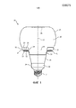
фиг. 1 схематично изображает поперечное сечение светового устройства в соответствии с вариантом осуществления;FIG. 1 schematically depicts a cross section of a lighting device in accordance with an embodiment;
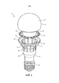
фиг.2 схематично изображает покомпонентный вид светового устройства в соответствии с вариантом осуществления;figure 2 schematically depicts an exploded view of a lighting device in accordance with an embodiment;
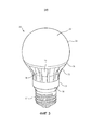
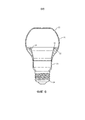
фиг. 3 схематично изображает вид в перспективе светового устройства в соответствии с вариантом осуществления;FIG. 3 schematically depicts a perspective view of a lighting device in accordance with an embodiment;
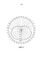
фиг. 4 изображает график светового распределения светового устройства в соответствии с вариантом осуществления;FIG. 4 is a graph of light distribution of a light device according to an embodiment;
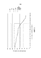
фиг. 5 изображает график относительной силы света светового устройства в соответствии с вариантом осуществления; иFIG. 5 is a graph of the relative luminous intensity of a light device in accordance with an embodiment; and
фиг. 6 схематично изображает вид сечения светового устройства в соответствии с вариантом осуществления.FIG. 6 schematically depicts a cross-sectional view of a lighting device in accordance with an embodiment.
ПОДРОБНОЕ ОПИСАНИЕ ВАРИАНТОВ ОСУЩЕСТВЛЕНИЯDETAILED DESCRIPTION OF EMBODIMENTS
Следует понимать, что эти чертежи являются всего лишь схематичными и выполнены не в масштабе. Следует также понимать, что для обозначения одних тех же или подобных частей устройства по всем фигурам используются одни и те же ссылочные позиции.It should be understood that these drawings are merely schematic and not drawn to scale. It should also be understood that the same reference numbers are used to refer to the same or similar parts of the device in all figures.
На фиг. 1 схематично изображено поперечное сечение варианта осуществления светового устройства 10 в соответствии с вариантом осуществления настоящего изобретения. Фиг. 2 схематично изображает световое устройство по фиг. 1 в покомпонентном виде, а фиг. 3 схематично изображает световое устройство по фиг. 1 на виде в перспективе. Если определенно не оговорено иное, на этих фигурах одни и те же ссылочные позиции обозначают одни и те же элементы.In FIG. 1 is a schematic cross-sectional view of an embodiment of a
Световое устройство 10 содержит луковицеобразный элемент 20, заходящий в теплоотвод 30 с образованием общей формы светового устройства 10. Этот луковицеобразный элемент 20 обычно выполнен из материала, по которому может проходить свет, такого как стекло или полимер оптического класса, например, поликарбонат, полиметилметакрилат (ПММА), полиэтилентерефталат (ПЭТ) или им подобные. Материал может быть прозрачным или полупрозрачным; если, например, материал является полупрозрачным материалом, то прямой вид внутренних элементов светового устройства 10 для улучшения эстетического внешнего вида этого светового устройства 10 для внешнего наблюдателя может быть закрыт.The
Теплоотвод 30 может быть изготовлен из любого пригодного теплопроводящего материала, такого как подходящий металл. В качестве не ограничивающего примера, теплоотвод 30 может быть выполнен из алюминия или из алюминиевого сплава, хотя специалисту в данной области будет очевидно, что могут быть использованы также и другие металлы или сплавы металлов. Теплоотвод 30 содержит кольцевой участок 31, включающий в себя кольцевой участок 33 поверхности и ободок 32, продолжающийся вверх от внешней кромки кольцевого участка 31 в направлении луковицеобразного элемента 20, а именно, - в направлении первого участка 21 поверхности луковицеобразного элемента 20. В одном варианте осуществления ободок 32 продолжается в направлении луковицеобразного элемента 20 и контактирует с ним.The
Кольцевой участок 33 поверхности определяет центральное отверстие 37 в теплоотводе 30. Кольцевой участок 31 определяет держатель для множества твердотельных световых элементов 50, которые либо установлены непосредственно на кольцевом участке 33 поверхности, либо смонтированы на кольцевом держателе 52, каковой держатель сам может быть установлен на кольцевом участке 33 поверхности. Кольцевому держателю 52 обычно приданы такие размеры, чтобы он совпадал с кольцевым участком 33 поверхности. Для удержания твердотельных световых элементов 50 может быть использован любой подходящий кольцевой держатель 52, например, печатная плата и т.п.An
В одном варианте осуществления твердотельные световые элементы 50 являются светодиодами. Для установки в световое устройство 10 могут быть рассмотрены светодиоды любого подходящего типа. Твердотельные световые элементы 50 могут быть выбраны таким образом, чтобы каждый твердотельный световой элемент 50 испускал свет одного и того же цвета или одной и той же цветовой температуры. Альтернативно, в световое устройство 10 может быть включена смесь твердотельных световых элементов 50, испускающих свет разного цвета или с разными цветовыми температурами.In one embodiment, the solid state
В одном варианте осуществления теплоотвод 30 содержит дополнительный участок 34, сцепленный с цоколем 14 светового устройства 10. На фиг. 1-3 - всего лишь в качестве не ограничивающего примера - показан винтовой цоколь 14; следует понимать, что цоколь 14 может иметь любую подходящую форму, такую как байонетный цоколь, цоколь типа GU, цоколь типа МР и т.д. Дополнительный участок 34 может продолжаться от цоколя 14 в сторону кольцевого участка 31. Однако в особенно предпочтительном варианте осуществления дополнительный участок 34 пространственно отделен от кольцевого участка 31. В этом варианте осуществления теплоотвод 30 может дополнительно включать в себя множество ребер 35, каждое из которых продолжается от дополнительного участка 34 к кольцевому участку 31.In one embodiment, the
Вид или форма ребер 35 специально не ограничены; эти ребра 35 могут иметь любой подходящий вид или форму. В одном варианте осуществления кольцевой участок 31 теплоотвода 30 имеет больший наружный диаметр, чем дополнительный участок 34, при этом ребра 35 могут быть искривленными внутрь относительно кольцевого участка 31 в направлении дополнительного участка 34, как показано, в частности, на фиг. 2. Ребра 35 могут продолжаться от кольцевого участка 31 к дополнительному участку 34 любым подходящим образом. В качестве не ограничивающего примера, ребра 35 могут продолжаться от нижней части кольцевого участка 33 поверхности к наружной поверхности дополнительного участка 34 теплоотвода 30, хотя специалисту в данной области будет понятно, что в равной степени возможны многие другие подходящие конфигурации.The appearance or shape of the
Ребра 35 обычно отделены одно от другого посредством множества соответствующих зазоров 36. Как будет объяснено более подробно ниже, эти зазоры 36 могут служить в качестве областей выхода света, для того чтобы увеличить угловой диапазон светового распределения, обеспечиваемого световым устройством 10. Зазоры 36 могут содержать материал, свет через который может проходить, например, прозрачное или полупрозрачное стекло или полимер, так чтобы внутренние элементы светового устройства в отверстия 36 видны не были. Альтернативно, зазоры 36 могут оставаться незакрытыми. Это, например, является приемлемым исполнением, если луковицеобразный элемент 20 продолжается в теплоотвод 30 таким образом, что зазоры 36 закрыты частью луковицеобразного элемента 20, как будет объяснено более подробно ниже.The
Луковицеобразному элементу 20, как правило, придана такая форма, что этот луковицеобразный элемент 20 включает в себя первый участок 21 поверхности, направленной в сторону светоизлучающей поверхности твердотельных световых элементов 50, и второй участок 22 поверхности, продолжающийся от первого участка 21 поверхности через центральное отверстие 37 теплоотвода 30. Таким образом, первый участок 21 поверхности, второй участок 22 поверхности, кольцевой участок 31 поверхности и ободок 32 "взаимодействуют" между собой с образованием отсека 40, тороидального или в форме баранки, в котором расположены твердотельные световые элементы 50. Вследствие ограниченного контакта между луковицеобразным элементом 20 и твердотельными световыми элементами 50, с одной стороны, и относительно большой контактной площади между теплоотводом 30 и твердотельными световыми элементами 50, с другой стороны, тепло, созданное твердотельными световыми элементами 50, может хорошо поддаваться управлению, и при этом было найдено, что могут быть построены световые устройства, создающие световой поток, эквивалентный потоку 100 ваттной электрической лампочки, без того, чтобы температуры множественных твердотельных световых элементов 50, необходимые для получения такого светового потока, превышали приемлемые допуски.The onion-shaped
Луковицеобразный элемент 20 может действовать в качестве световодного элемента для света, испускаемого твердотельными световыми элементами 50, который может быть введен в световодный элемент через, соответственно, первый участок 21 поверхности и второй участок 22 поверхности луковицеобразного элемента 20. Для того чтобы увеличить количество света, введенного в этот световодный элемент, ободок 32 кольцевого участка 31 теплоотвода 30 может быть отражающим, таким, чтобы свет, испущенный твердотельными световыми элементами 50 в направлении этого ободка 32, перенаправлялся (отражался) ободком 32 в направлении первого участка 21 поверхности или второго участка 22 поверхности. По тем же самым причинам может быть отражающим кольцевой участок 33 поверхности кольцевого участка 31 теплоотвода 30. Чтобы достичь требуемой отражательной способности, ободок 32 и/или кольцевой участок 33 поверхности могут быть выполнены из отражающего материала, например, из полированного металла или сплава металла, такого как алюминий или его сплав, или же они могут быть покрыты отражающим слоем, таким как отражающая фольга,The
Теперь отметим, что эта конфигурация позволяет использовать относительно тонкий луковицеобразный элемент 20, потому что свет, испущенный твердотельными световыми элементами 50, вводится в световодный элемент через его внешнюю поверхность, а не посредством обеспечения углубления в торцевой поверхности этого световодного элемента, как это описано, например, в публикации WO 2013/017612 А2. Например, как показано на фиг. 6, в некоторых вариантах осуществления толщина стенки луковицеобразного элемента 20 может быть выбрана приблизительно в диапазоне 20-50% от ширины отдельного твердотельного светового элемента 50. Другими словами, толщина стенки луковицеобразного элемента 20 меньше, чем типичная ширина твердотельного светового элемента 50. Например, типичная ширина твердотельного светового элемента 50 может составлять 3 мм, при этом типичная ширина стенки луковицеобразного элемента 20 лежит в диапазоне 0,5-1,5 мм, например равна 1 мм. Следовательно, луковицеобразный элемент 20, используемый в вариантах осуществления светового устройства 10, может выполняться относительно тонким, т.е. может быть выполнен с использованием относительно малого количества материала, что, следовательно, улучшает световую эффективность светового устройства 10, поскольку потери света, например, в результате поглощения, как правило, пропорциональны количеству материала, через который должен пройти свет.Now note that this configuration allows the use of a relatively thin
Вторая часть поверхности 22 луковицеобразного элемента 20, как правило, продолжается от первого участка 21 поверхности через центральное отверстие 37 теплоотвода 30, таким образом, что при этом по меньшей мере часть второго участка 22 поверхности расположена ниже плоскости центрального отверстия 37, т.е. расположена между центральным отверстием 37 и цоколем 14. Это позволяет свету выходить из луковицеобразного элемента 20, действующего в качестве световодного элемента, в областях ниже вышеупомянутой плоскости центрального отверстия 37. Это особенно выгодно, если теплоотвод 30 включает в себя множество зазоров 36, так что свет, выходящий из луковицеобразного элемента 20 ниже плоскости центрального отверстия 37, может выходить из светового устройства 10 через множество зазоров 36. Как сразу очевидно, это может значительно улучшить световое распределение, создаваемое световым устройством 10, что будет более подробно показано ниже. Второй участок 22 поверхности может частично перекрывать зазоры 36, то есть луковицеобразный элемент 20 может заканчиваться между кольцевым участком 31 и дополнительным участком 34 радиатора 30. Альтернативно, второй участок 22 поверхности может полностью покрывать зазоры 36, то есть луковицеобразный элемент 20 при этом может заканчиваться либо около, либо в дополнительном участке 34 радиатора 30. В этом последнем варианте осуществления не требуется, чтобы зазоры 36 включали покрывающий материал, поскольку покрытие зазоров 36 обеспечивается луковицеобразным элементом 20.The second part of the
Луковицеобразный элемент 20 может иметь любую подходящую форму. В примерном варианте осуществления луковицеобразный элемент 20 может содержать луковицеобразный корпус 25, соединенный с сужающимся кольцевым участком 24 посредством соединительного участка 23. Соединительный участок 23 может включать в себя первый участок 21 поверхности, а сужающийся кольцевой участок 24 может включать в себя второй участок 22 поверхности. Соединительному участку 23 могут быть приданы такие размеры, чтобы внешняя кромка между соединительным участком 23 и луковицеобразным корпусом 25 совпадала с кольцевым участком 31 теплоотвода 30, а внутренняя кромка между соединительным участком 23 и сужающимся кольцевым участком 24 позволяла сужающемуся кольцевому участку 24 продолжаться через центральное отверстие 37 теплоотвода 30.The
Аналогичным образом, любую подходящую форму может иметь луковицеобразный корпус 25, такую как в виде непрерывно искривленного корпуса, искривленного корпуса, содержащего плоский верхний участок, и так далее. Луковицеобразному корпусу 20 может быть придана такая форма, чтобы он соответствовал форме ранее существовавших лампочек накаливания, так чтобы световое устройство 10 по внешнему виду было как можно больше похоже на такие традиционные световые устройства.Similarly, any suitable shape may have a
В одном варианте осуществления световое устройство 10 на внутренней поверхности луковицеобразного элемента 20, такой как внутренняя поверхность луковицеобразного корпуса 25, дополнительно содержит отражательный элемент, такой как отражающее покрытие 26, или любой другой подходящий отражающий элемент внутри луковицеобразного элемента 20 для перенаправления света в сторону нижней части светового устройства 10, например, в направлении зазоров 36.In one embodiment, the
В случае наличия отражающего покрытия 26 это отражающее покрытие 26, предпочтительно, центрировано по оптической оси 12 светового устройства 10 и может быть выполнено с возможностью отражения света, испускаемого твердотельными световыми элементами 50 через центральное отверстие 37, например, в направлении зазоров 36, когда они присутствуют, так чтобы интенсивность света, выходящего из светового устройства в области между центральным отверстием 37 и цоколем 14, могла бы увеличиться.If there is a
Это, например, относится к такому случаю, когда угловая зависимость в распределении силы света, даваемой световым устройством 10, должна поддерживаться в пределах заранее заданных допусков, к такому как, например, случай, когда световое устройство 10 должно соответствовать требованиями стандарта Energy Star. Часть этих требований указывает, что 90% от силы света, даваемой световым устройством, должны изменяться не более чем на 25% от средней силы света, и что вся сила света, даваемая световым устройством, должна изменяться не более чем на 50% от средней силы света, даваемой световым устройством.This, for example, refers to the case where the angular dependence in the distribution of the light intensity given by the
Для того чтобы соответствовать требованиям, таким как требования стандарта Energy Star, отражательному участку 26 могут быть приданы соответствующие размеры. Например, отражательный участок 26 может иметь круговую форму, центрированную по оптической оси 12 светового устройства 10, при этом круговая форма имеет диаметр, который имеет определенное соотношение с максимальным диаметром луковицеобразный элемент 20. В некоторых вариантах осуществления диаметр круговой формы может составлять 25-50% от максимального диаметра луковицеобразный элемент 20. Правильный выбор размеров отражательного участка 26 обеспечивает, что бы соответствующее количество света этим отражательным участком 26 отражалось в направлении нижней половины, например, в направлении зазоров 36, светового устройства 10 таким образом, чтобы распределение света, даваемое световым устройством 10, могло бы удовлетворять требованиям к распределению света, таким как вышеупомянутые требования Energy Star. Например, для достижения требуемого распределения света круговой отражательный участок 26 для лампочки стандартного размера может иметь диаметр около 20 мм.In order to meet requirements such as those of the Energy Star standard,
Для отражательного участка 26 может быть использован любой подходящий материал отражающего покрытия. Особенно простой способ нанесения материала покрытия на луковицеобразный элемент 20 состоит в том, чтобы обеспечить дисперсию или раствор материала отражающего покрытия в соответствующем растворителе, выложить предопределенный объем дисперсии или раствора в луковицеобразный элемент 20 и выпаривать растворитель, чтобы он остался с задней стороны отражательного участка 26 на участке внутренней поверхности луковицеобразного элемента 20. В примерном варианте осуществления таким образом может быть выложена дисперсия частиц ΤίΟ2, например, взвеси ΤίΟ2 в растворителе, таком как бутилакрилат, с последующим удалением бутилакрилата и формированием образованного из ΤίΟ2 отражательного участка 26. Однако следует подчеркнуть, что специалисту в данной области будет сразу очевидно, что для этой цели могут быть использованы и другие подходящие отражающие материалы и/или другие подходящие растворители. Поскольку многие из таких материалов и растворителей сами по себе хорошо известны, ради краткости более подробно это поясняться не будет.For the
В некоторых вариантах осуществления настоящего изобретения световым устройством 10 является электрическая лампочка, хотя следует понимать, что альтернативные варианты осуществления настоящего изобретения не обязательно ограничиваются этим.In some embodiments of the present invention, the
Фиг. 4 изображает график в полярных координатах светового выхода светового устройства 10 в соответствии с фиг. 3, в котором множество ребер 35 образует множество зазоров 36 между кольцевым участком 31 и дополнительным участком 34 теплоотвода 30, и в котором на внутренней поверхности луковицеобразного корпуса 25 присутствует отражательный участок 26, и он центрирован по оптической оси 12, как пояснялось ранее. В этом варианте осуществления луковицеобразный корпус 20 представляет собой пластмассовый корпус (поликарбонат), а сужающийся кольцевой участок 24 луковицеобразного элемента 20 полностью закрывает зазоры 36.FIG. 4 is a graph in polar coordinates of the light output of the
Этот график в полярных координатах ясно показывает, что может быть достигнуто распределение света по всему 360°-му диапазону, обеспечивая тем самым, чтобы световое устройство 10 по своему ("световому") внешнему виду было похожим на обычные электрические лампочки, такие как электрические лампочки накаливания. Средняя сила света светового устройства 10 составляет около 600 лм, при этом полный разброс силы света перекрывает диапазон от около 400 до 1.000 лм, так что можно признать, что световое устройство 10 по фиг. 3 соответствует требованиям стандарта Energy Star.This graph in polar coordinates clearly shows that light distribution over the entire 360 ° range can be achieved, thereby ensuring that the
Это видно также на фиг. 5, которая показывает относительную силу света (%) светового устройства 10 в функции светового угла излучения по отношению к оптической оси 12 светового устройства 10. Сплошная рамка на фиг. 5 отмечает допустимое 25%-е отклонение от средней силы света (Energy Star) для 90% измеренных точек светового устройства 10, а пунктирные рамки отмечают области за пределами допустимого 50%-го отклонения от этой средней интенсивности свечения. Поскольку по крайней мере 90% измеренной силы света свечения светового устройства 10 лежит внутри сплошной рамки, и ни одно из измерений светового устройства 10 не лежит внутри одной из пунктирных рамок, то можно видеть, что световое устройство 10 соответствует требованиям стандарта Energy Star, который, например, используется в США.This is also seen in FIG. 5, which shows the relative luminous intensity (%) of the
Световое устройство 10 в соответствии с одним или более вариантами осуществления настоящего изобретения, может быть с успехом включено в светильник, такой как держатель светового устройства, например потолочный светильник, или прибор, в который встроено это световое устройство, например, кухонная вытяжка или тому подобное. Специалисту в данной области будут очевидны и другие подходящие типы светильников, например, рекламный светильник, содержащий матрицу трубчатых световых устройств, и так далее.A
Следует отметить, что вышеупомянутые варианты осуществления иллюстрируют, а не ограничивают изобретение, и что специалисты в данной области техники способны разработать множество альтернативных вариантов осуществления, не выходя за рамки объема приложенных пунктов формулы изобретения. В формуле изобретения любые ссылочные позиции, помещенные между круглыми скобками, не должны истолковываться как ограничивающие пункты формулы изобретения. Слово "содержащий" не исключает присутствия элементов или этапов, отличных от тех, которые перечислены в формуле изобретения. Признаки единственного числа не исключает присутствия множества таких элементов. Изобретение может быть реализовано посредством аппаратных средств, содержащих несколько отдельных элементов. В пункте формулы устройства, перечисляющем несколько средств, этих несколько средств могут быть воплощены посредством одного и того же аппаратного средства. Сам по себе тот факт, что определенные размеры перечислены в различных взаимно зависимых пунктах формулы изобретения, не указывает на то, что для получения какого-либо преимущества не может быть использована комбинация этих измерений.It should be noted that the above embodiments illustrate, but not limit, the invention, and that those skilled in the art are capable of developing many alternative embodiments without departing from the scope of the attached claims. In the claims, any reference characters placed between parentheses should not be construed as limiting the claims. The word “comprising” does not exclude the presence of elements or steps other than those listed in the claims. Signs of the singular does not preclude the presence of many such elements. The invention can be implemented by means of hardware containing several separate elements. In a claim of a device listing several means, these several means may be embodied by the same hardware. The mere fact that certain sizes are listed in various mutually dependent claims does not indicate that a combination of these measurements cannot be used to obtain any advantage.
Claims (20)
Applications Claiming Priority (5)
| Application Number | Priority Date | Filing Date | Title |
|---|---|---|---|
| CN2014075814 | 2014-04-21 | ||
| CNPCT/CN2014/075814 | 2014-04-21 | ||
| EP14172080 | 2014-06-12 | ||
| EP14172080.5 | 2014-06-12 | ||
| PCT/EP2015/057572 WO2015162004A1 (en) | 2014-04-21 | 2015-04-08 | Lighting device and luminaire |
Publications (3)
| Publication Number | Publication Date |
|---|---|
| RU2016145053A RU2016145053A (en) | 2018-05-21 |
| RU2016145053A3 RU2016145053A3 (en) | 2018-12-07 |
| RU2681309C2 true RU2681309C2 (en) | 2019-03-06 |
Family
ID=52998112
Family Applications (1)
| Application Number | Title | Priority Date | Filing Date |
|---|---|---|---|
| RU2016145053A RU2681309C2 (en) | 2014-04-21 | 2015-04-08 | Light device and luminaire |
Country Status (7)
| Country | Link |
|---|---|
| US (1) | US10041633B2 (en) |
| EP (1) | EP3134674B1 (en) |
| JP (1) | JP6571682B2 (en) |
| CN (1) | CN106233062B (en) |
| BR (1) | BR112016024404A2 (en) |
| RU (1) | RU2681309C2 (en) |
| WO (1) | WO2015162004A1 (en) |
Families Citing this family (2)
| Publication number | Priority date | Publication date | Assignee | Title |
|---|---|---|---|---|
| CN105805606A (en) * | 2014-12-31 | 2016-07-27 | 潘文莘 | Light emitting diode bulb structure |
| CN212929632U (en) * | 2020-04-08 | 2021-04-09 | 林建廷 | LED annular lamp structure |
Citations (10)
| Publication number | Priority date | Publication date | Assignee | Title |
|---|---|---|---|---|
| RU2313157C1 (en) * | 2006-06-09 | 2007-12-20 | Институт проблем технологии микроэлектроники и особочистых материалов Российской Академии Наук (ИПТМ РАН) | Method for producing visible light and luminescent sources using this method (alternatives) |
| RU2408816C2 (en) * | 2009-01-27 | 2011-01-10 | Виктор Викторович Сысун | White light-emitting diode lamp |
| RU2446346C2 (en) * | 2010-05-28 | 2012-03-27 | Государственное образовательное учреждение высшего профессионального образования "Новосибирский государственный технический университет" | Light-emitting diode-based lamp |
| RU2464488C2 (en) * | 2010-11-15 | 2012-10-20 | Виктор Викторович Сысун | Light diode lamp |
| US20120314420A1 (en) * | 2010-02-25 | 2012-12-13 | Shoji Yamamoto | Lighting apparatus |
| WO2013017612A2 (en) * | 2011-08-02 | 2013-02-07 | Osram Ag | An led lighting assembly and an led retrofit lamp having the led lighting assembly |
| US20130077285A1 (en) * | 2010-09-29 | 2013-03-28 | Toshiaki Isogai | Lamp |
| RU2481368C2 (en) * | 2008-12-18 | 2013-05-10 | 3М Инновейтив Пропертиз Компани | Coating composition |
| RU2489774C2 (en) * | 2007-11-29 | 2013-08-10 | Нития Корпорейшн | Light-emitting device and method of making said device |
| US20130335978A1 (en) * | 2012-06-13 | 2013-12-19 | Tsung-Hsien Huang | Led lamp assembly |
Family Cites Families (13)
| Publication number | Priority date | Publication date | Assignee | Title |
|---|---|---|---|---|
| AU2003205508A1 (en) | 2002-01-07 | 2003-07-24 | Patent - Treuhand - Gesellschaft Fur Elektrische Gluhlampen Mbh | Lamp |
| US7980728B2 (en) | 2008-05-27 | 2011-07-19 | Abl Ip Holding Llc | Solid state lighting using light transmissive solid in or forming optical integrating volume |
| JP2010015754A (en) * | 2008-07-02 | 2010-01-21 | Panasonic Corp | Lamp and lighting device |
| JP5328466B2 (en) * | 2009-04-24 | 2013-10-30 | シャープ株式会社 | Light bulb type lighting device |
| US20100320904A1 (en) | 2009-05-13 | 2010-12-23 | Oree Inc. | LED-Based Replacement Lamps for Incandescent Fixtures |
| US8128262B2 (en) | 2010-03-30 | 2012-03-06 | Abl Ip Holdings Llc | Lighting applications with light transmissive optic contoured to produce tailored light output distribution |
| JP5687023B2 (en) * | 2010-10-12 | 2015-03-18 | 株式会社林技術研究所 | Planar light emitting device |
| JP5612491B2 (en) * | 2011-01-14 | 2014-10-22 | パナソニック株式会社 | Light source for illumination |
| CN202284728U (en) * | 2011-07-04 | 2012-06-27 | 欧司朗股份有限公司 | Lighting device |
| US9255666B2 (en) * | 2011-11-10 | 2016-02-09 | Epistar Corporation | Illumination apparatus |
| US9175813B2 (en) | 2012-03-30 | 2015-11-03 | 3M Innovative Properties Company | Electrical connectors for solid state light |
| JP2013229195A (en) * | 2012-04-26 | 2013-11-07 | Hitachi Appliances Inc | Bulb-type lighting device |
| CN203176866U (en) | 2013-04-23 | 2013-09-04 | 天津圣达芯光电子科技有限公司 | Novel remote fluorescent light-emitting diode (LED) bulb lamp |
-
2015
- 2015-04-08 CN CN201580020846.4A patent/CN106233062B/en active Active
- 2015-04-08 JP JP2016563182A patent/JP6571682B2/en active Active
- 2015-04-08 RU RU2016145053A patent/RU2681309C2/en active
- 2015-04-08 US US15/305,781 patent/US10041633B2/en active Active
- 2015-04-08 BR BR112016024404A patent/BR112016024404A2/en not_active IP Right Cessation
- 2015-04-08 WO PCT/EP2015/057572 patent/WO2015162004A1/en active Application Filing
- 2015-04-08 EP EP15718165.2A patent/EP3134674B1/en active Active
Patent Citations (10)
| Publication number | Priority date | Publication date | Assignee | Title |
|---|---|---|---|---|
| RU2313157C1 (en) * | 2006-06-09 | 2007-12-20 | Институт проблем технологии микроэлектроники и особочистых материалов Российской Академии Наук (ИПТМ РАН) | Method for producing visible light and luminescent sources using this method (alternatives) |
| RU2489774C2 (en) * | 2007-11-29 | 2013-08-10 | Нития Корпорейшн | Light-emitting device and method of making said device |
| RU2481368C2 (en) * | 2008-12-18 | 2013-05-10 | 3М Инновейтив Пропертиз Компани | Coating composition |
| RU2408816C2 (en) * | 2009-01-27 | 2011-01-10 | Виктор Викторович Сысун | White light-emitting diode lamp |
| US20120314420A1 (en) * | 2010-02-25 | 2012-12-13 | Shoji Yamamoto | Lighting apparatus |
| RU2446346C2 (en) * | 2010-05-28 | 2012-03-27 | Государственное образовательное учреждение высшего профессионального образования "Новосибирский государственный технический университет" | Light-emitting diode-based lamp |
| US20130077285A1 (en) * | 2010-09-29 | 2013-03-28 | Toshiaki Isogai | Lamp |
| RU2464488C2 (en) * | 2010-11-15 | 2012-10-20 | Виктор Викторович Сысун | Light diode lamp |
| WO2013017612A2 (en) * | 2011-08-02 | 2013-02-07 | Osram Ag | An led lighting assembly and an led retrofit lamp having the led lighting assembly |
| US20130335978A1 (en) * | 2012-06-13 | 2013-12-19 | Tsung-Hsien Huang | Led lamp assembly |
Also Published As
| Publication number | Publication date |
|---|---|
| WO2015162004A1 (en) | 2015-10-29 |
| JP2017514277A (en) | 2017-06-01 |
| EP3134674B1 (en) | 2018-06-13 |
| US10041633B2 (en) | 2018-08-07 |
| CN106233062B (en) | 2019-06-28 |
| RU2016145053A (en) | 2018-05-21 |
| CN106233062A (en) | 2016-12-14 |
| BR112016024404A2 (en) | 2017-08-15 |
| EP3134674A1 (en) | 2017-03-01 |
| JP6571682B2 (en) | 2019-09-04 |
| RU2016145053A3 (en) | 2018-12-07 |
| US20170045184A1 (en) | 2017-02-16 |
Similar Documents
| Publication | Publication Date | Title |
|---|---|---|
| EP3097348B1 (en) | Lighting device and luminaire | |
| JP6549802B2 (en) | Lighting device | |
| US8608341B2 (en) | LED luminaire | |
| EP2769142B1 (en) | Lighting device with omnidirectional light distribution | |
| JP6045506B2 (en) | LED bulb with light scattering optical structure | |
| JP6236097B2 (en) | Illumination device and optical component thereof | |
| JP2010129501A (en) | Illumination device and luminaire | |
| US20120314413A1 (en) | Constructive occlusion lighting system and applications thereof | |
| RU2681309C2 (en) | Light device and luminaire | |
| US9995476B2 (en) | Lighting device and luminaire | |
| JP2016212371A (en) | Luminous flux control member, light-emitting device and luminaire | |
| JP5620872B2 (en) | LED light emitting device | |
| JP2016518013A (en) | LED lamp with controlled light distribution | |
| KR101549028B1 (en) | Lighting apparatus | |
| JP7053968B2 (en) | Solid lamp | |
| KR200473142Y1 (en) | Led light bulb | |
| WO2016181789A1 (en) | Light beam control member, light-emitting device, and illumination device |