RU2677503C1 - Device for delivery of devices to horizontal well based on borehole torpedo - Google Patents
Device for delivery of devices to horizontal well based on borehole torpedo Download PDFInfo
- Publication number
- RU2677503C1 RU2677503C1 RU2018108864A RU2018108864A RU2677503C1 RU 2677503 C1 RU2677503 C1 RU 2677503C1 RU 2018108864 A RU2018108864 A RU 2018108864A RU 2018108864 A RU2018108864 A RU 2018108864A RU 2677503 C1 RU2677503 C1 RU 2677503C1
- Authority
- RU
- Russia
- Prior art keywords
- devices
- borehole
- torpedo
- electric motor
- delivery
- Prior art date
Links
Images
Classifications
-
- E—FIXED CONSTRUCTIONS
- E21—EARTH OR ROCK DRILLING; MINING
- E21B—EARTH OR ROCK DRILLING; OBTAINING OIL, GAS, WATER, SOLUBLE OR MELTABLE MATERIALS OR A SLURRY OF MINERALS FROM WELLS
- E21B23/00—Apparatus for displacing, setting, locking, releasing or removing tools, packers or the like in boreholes or wells
- E21B23/14—Apparatus for displacing, setting, locking, releasing or removing tools, packers or the like in boreholes or wells for displacing a cable or a cable-operated tool, e.g. for logging or perforating operations in deviated wells
-
- E—FIXED CONSTRUCTIONS
- E21—EARTH OR ROCK DRILLING; MINING
- E21B—EARTH OR ROCK DRILLING; OBTAINING OIL, GAS, WATER, SOLUBLE OR MELTABLE MATERIALS OR A SLURRY OF MINERALS FROM WELLS
- E21B47/00—Survey of boreholes or wells
- E21B47/01—Devices for supporting measuring instruments on drill bits, pipes, rods or wirelines; Protecting measuring instruments in boreholes against heat, shock, pressure or the like
- E21B47/017—Protecting measuring instruments
Landscapes
- Life Sciences & Earth Sciences (AREA)
- Engineering & Computer Science (AREA)
- Geology (AREA)
- Mining & Mineral Resources (AREA)
- Physics & Mathematics (AREA)
- Environmental & Geological Engineering (AREA)
- Fluid Mechanics (AREA)
- General Life Sciences & Earth Sciences (AREA)
- Geochemistry & Mineralogy (AREA)
- Geophysics (AREA)
- Earth Drilling (AREA)
Abstract
Description
Изобретение относится к нефтегазодобывающей промышленности, в частности, к устройствам для доставки приборов в горизонтальную скважину.The invention relates to the oil and gas industry, in particular, to devices for delivering devices to a horizontal well.
Известно устройство для доставки геофизических приборов в горизонтальную скважину, содержащее геофизический кабель и средство доставки, выполненное в виде кожуха, внутри которого установлен гидравлический движитель, выполненный в виде двух винтов, вращающихся в одну сторону, и привода, выполненного в виде электрического двигателя. Гидравлический движатель установлен в корпусе с зазором. SU 1208199 А1, опубл. 30.01.1986.A device is known for delivering geophysical instruments to a horizontal well, comprising a geophysical cable and a delivery means made in the form of a casing, inside of which a hydraulic propeller is made, made in the form of two screws rotating in one direction, and a drive made in the form of an electric motor. The hydraulic drive is installed in the housing with a gap. SU 1208199 A1, publ. 01/30/1986.
Недостатком указанного устройства является, скручивание геофизического кабеля вследствие действия реактивного вращающегося момента на корпус устройства из-за того, что оба винта вращаются в одну сторону.The disadvantage of this device is the twisting of the geophysical cable due to the action of reactive torque on the device due to the fact that both screws rotate in the same direction.
Ближайшим аналогом предлагаемого технического решения является устройство для доставки геофизических приборов в скважину, содержащее геофизический кабель и средство перемещения геофизических приборов в скважине, выполненное в виде кожуха, внутри которого установлен гидравлический движитель, выполненный в виде двух гребных винтов, соединенный с приводом, причем привод выполнен в виде электродвигателя с механизмом передачи, например редуктором или мультипликатором, расположен в геометрическом корпусе и размещен в кожухе с кольцевым зазором, а два гребных винта выполнены с возможностью вращения в противоположные стороны, расположены за пределами корпуса и защищены кожухом. RU 2363831 С1, опубл. 10.08.2009.The closest analogue of the proposed technical solution is a device for the delivery of geophysical instruments into the well, containing a geophysical cable and means for moving the geophysical instruments in the well, made in the form of a casing, inside which a hydraulic propeller is made in the form of two propellers connected to the drive, and the drive is made in the form of an electric motor with a transmission mechanism, for example a gearbox or a multiplier, is located in a geometric housing and placed in a casing with an annular the gap, and two propellers are made to rotate in opposite directions, located outside the housing and protected by a casing. RU 2363831 C1, publ. 08/10/2009.
Недостаток указанного изобретения заключается в том, что тяга, создаваемая двумя винтами, расположенными на переднем конце устройства и питаемыми одним электродвигателем, не всегда достаточна для движения комплекса «тяговое устройство - геофизические приборы» на горизонтальном участке скважины.The disadvantage of this invention is that the traction created by two screws located on the front end of the device and powered by one electric motor is not always sufficient for the movement of the "traction device - geophysical instruments" complex on the horizontal section of the well.
Технической задачей, на решение которой направлено заявляемое изобретение, является разработка устройства для доставки приборов в горизонтальную скважину на основе скважинной торпеды, обеспечивающей повышение собственно тяги устройства.The technical problem to be solved by the claimed invention is directed is the development of a device for delivering devices to a horizontal well based on a borehole torpedo, which increases the actual thrust of the device.
Техническим результатом от реализации изобретения является повышение скорости и надежности доставки приборов в горизонтальную скважину.The technical result from the implementation of the invention is to increase the speed and reliability of the delivery of devices in a horizontal well.
Указанный технический результат достигается тем, что в устройстве для доставки приборов в горизонтальную скважину, включающем кабель, блок оборудования, в котором размещены приборы, и средство перемещения приборов, внутри цилиндрического герметичного корпуса которого размещен электрический двигатель, а два гребных винта с возможностью вращения в противоположные стороны расположены за пределами корпуса и защищены кожухом, согласно изобретению, средство перемещения приборов имеет форму скважинной торпеды, корпус которой содержит камеру, разбитую на герметичные отсеки, причем гребные винты установлены на противоположных концах корпуса скважинной торпеды, приводятся в движение каждый собственным электрическим двигателем через собственный вал, а кабель проходит через блок оборудования и приводной полый вал заднего электродвигателя до переднего электродвигателя.The specified technical result is achieved by the fact that in the device for delivering devices to a horizontal well, including a cable, a unit of equipment in which the devices are located, and a means of moving devices, inside a cylindrical sealed enclosure of which an electric motor is placed, and two propellers rotatably opposed the sides are located outside the housing and protected by a casing, according to the invention, the means for moving the devices has the form of a borehole torpedo, the housing of which contains py, broken into leakproof compartments, wherein propellers are mounted on opposite ends of a downhole torpedo hull, each driven by its own electric motor via its own shaft, and the cable passes through the equipment unit, and a drive motor a hollow shaft to the rear of the front motor.
Указанные отличительные признаки существенны.These distinguishing features are significant.
Достижению технического результата также способствует следующее.The achievement of the technical result also contributes to the following.
Отсеки камеры заполнены жидкостью, в объеме необходимом для придания устройству заданной плавучести.The compartments of the chamber are filled with liquid in the amount necessary to give the device a given buoyancy.
На средстве перемещения приборов установлены центраторы.Centralizers are installed on the instrument transfer device.
Блок оборудования имеет форму цилиндра.The equipment block has the shape of a cylinder.
В скважинной торпеде с помощью камеры, состоящей из герметичных отсеков, которые заполняются жидкостью, например, буровым раствором, в зависимости от плотности среды в скважине, обеспечивается требуемая плавучесть, а сама скважинная торпеда содержит два движителя, расположенные на ее противоположных концах. Каждый движитель представляет собой гребной винт, соединенный с электрическим двигателем прямой передачей. Электродвигатели связаны с наземным пунктом управления кабелем. Гребные винты вращаются в противоположные стороны для компенсации вращающего момента, действующего на корпус скважинной торпеды. Передний винт является тянущим и защищен кожухом, не позволяющим крупным частицам породы попадать на винт и заклинивать его. Задний винт является толкающим и также защищен кожухом. Кабель проходит через блок оборудования и приводной полый вал заднего электродвигателя до переднего электродвигателя.In a borehole dashboard using a chamber consisting of sealed compartments that are filled with fluid, for example, drilling fluid, depending on the density of the medium in the borehole, the required buoyancy is provided, and the borehole torpedo itself contains two propulsors located at its opposite ends. Each propeller is a propeller connected to a direct-drive electric motor. Electric motors are connected to the ground control point of the cable. The propellers rotate in opposite directions to compensate for the torque acting on the borehole torpedo body. The front screw is a pulling and protected by a casing that does not allow large particles of rock to fall on the screw and jam it. The rear screw is pushing and is also protected by a casing. The cable passes through the equipment unit and the drive hollow shaft of the rear motor to the front motor.
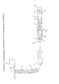
На фиг. приведена схема предлагаемого устройства, поясняющая сущность изобретения.In FIG. a diagram of the proposed device illustrates the essence of the invention.
Средство перемещения приборов в форме скважинной торпеды содержит камеру 1, состоящую из герметичных отсеков, которые заполняются жидкостью, например, буровым раствором, в зависимости от плотности среды в скважине 2, обеспечивая требуемую плавучесть. Гребные винты 3 и 4, соединены с электрическими двигателями 5 и 6, валом 7 и полым валом 8, обеспечивающими прямую передачу, расположены на противоположных концах скважинной торпеды. Сквозь полый вал 8 проходит кабель 10, который также проходит через задний винт 4 и полый ротор электродвигателя 6. Управление двигателями осуществляется из наземного пункта управления 9, например, от частотных преобразователей, присоединяемых кабелем 10.The means for moving devices in the form of a borehole torpedo contains a chamber 1, consisting of sealed compartments that are filled with fluid, for example, drilling fluid, depending on the density of the medium in the
Доставку в горизонтальную скважину приборов, находящихся в блоке оборудования 11, с помощью данного средства доставки осуществляют следующим образом.Delivery to the horizontal well of devices located in the unit of
Скважинную торпеду, соединенную через кабель 10, проходящий через блок оборудования 11, приводной полый вал заднего электродвигателя до переднего электродвигателя, спускают в скважину. При достижении скважинной торпедой горизонтального участка скважины включают с пункта управления 9 электродвигатели 5 и 6, которые приводят в движение гребные винты 3 и 4, создающие, соответственно, тянущую и толкающую силы, приложенные к корпусу 12 скважинной торпеды. Гребные винты вращаются в противоположные стороны для компенсации вращающего момента, действующего на корпус 12 скважинной торпеды. При этом передний винт 3 является тянущим и защищен кожухом 13, не позволяющим крупным частицам попадать на винт и заклинивать его. Задний винт 4 является толкающим и также защищен кожухом 14. Скважинная торпеда снабжена центраторами 15.A downhole torpedo connected through a
Подъем скважинной торпеды с приборами может быть осуществлен вытягиванием с помощью кабеля 10, а при большом весе могут быть использованы гребные винты 3 и 4, работающие в реверсивном режиме.Raising a borehole torpedo with devices can be carried out by pulling with
Повышение скорости доставки обеспечивается за счет регулирования плавучести скважинной торпеды вместе с приборами и реализуется путем заполнения герметичных отсеков камеры жидкостью, например, буровым раствором, в зависимости от плотности среды в скважине. Увеличение тягового усилия торпеды обеспечивается за счет разнесения двух гребных винтов, приводимых в движение каждый своим электродвигателем.An increase in the delivery speed is ensured by controlling the buoyancy of the borehole torpedo together with the devices and is realized by filling the sealed chamber compartments with a liquid, for example, drilling mud, depending on the density of the medium in the well. The increase in traction of the torpedo is ensured by the separation of two propellers, each driven by its own electric motor.
Повышение надежности доставки приборов в горизонтальную скважину обеспечивается как за счет использования прямых передач от электродвигателей к гребным винтам, так и за счет увеличения тягового усилия, позволяющего преодолевать сложные участки скважины с заданным набором приборов.Improving the reliability of delivering devices to a horizontal well is ensured both by using direct transmissions from electric motors to propellers, and by increasing traction, which allows you to overcome complex sections of the well with a given set of devices.
Claims (3)
Priority Applications (1)
| Application Number | Priority Date | Filing Date | Title |
|---|---|---|---|
| RU2018108864A RU2677503C1 (en) | 2018-03-13 | 2018-03-13 | Device for delivery of devices to horizontal well based on borehole torpedo |
Applications Claiming Priority (1)
| Application Number | Priority Date | Filing Date | Title |
|---|---|---|---|
| RU2018108864A RU2677503C1 (en) | 2018-03-13 | 2018-03-13 | Device for delivery of devices to horizontal well based on borehole torpedo |
Publications (1)
| Publication Number | Publication Date |
|---|---|
| RU2677503C1 true RU2677503C1 (en) | 2019-01-17 |
Family
ID=65024983
Family Applications (1)
| Application Number | Title | Priority Date | Filing Date |
|---|---|---|---|
| RU2018108864A RU2677503C1 (en) | 2018-03-13 | 2018-03-13 | Device for delivery of devices to horizontal well based on borehole torpedo |
Country Status (1)
| Country | Link |
|---|---|
| RU (1) | RU2677503C1 (en) |
Cited By (1)
| Publication number | Priority date | Publication date | Assignee | Title |
|---|---|---|---|---|
| CN112211613A (en) * | 2020-10-16 | 2021-01-12 | 鞍山申阔机械制造有限公司 | A rotary safety magnetic positioning logging tool |
Citations (6)
| Publication number | Priority date | Publication date | Assignee | Title |
|---|---|---|---|---|
| SU137860A1 (en) * | 1960-08-02 | 1960-11-30 | Б.Л. Каплан | Borehole torpedo |
| SU1208199A1 (en) * | 1984-06-01 | 1986-01-30 | Всесоюзный научно-исследовательский и проектно-конструкторский институт геофизических исследований геологоразведочных скважин | Arrangement for running instrumentsq into hole |
| US5617604A (en) * | 1994-09-06 | 1997-04-08 | Erich; Richard R. | Pivoted roller cutter pipe cleaning tool |
| RU60133U1 (en) * | 2006-07-17 | 2007-01-10 | ОАО "Сибнефть-Ноябрьскнефтегазгеофизика" | DEVICE FOR DELIVERY OF DEVICES TO A HORIZONTAL WELL |
| RU2363836C2 (en) * | 2007-02-12 | 2009-08-10 | Общество с ограниченной ответственностью "Кубаньгазпром" | Procedure for lifting liquid from bottomhole of gas condensate wells with low gas factor under conditions of abnormally low reservoir pressure |
| RU2422761C1 (en) * | 2009-12-18 | 2011-06-27 | Георгий Константинович Пиранишвили | Acoustic self-guided torpedo with reduced engine noise |
-
2018
- 2018-03-13 RU RU2018108864A patent/RU2677503C1/en active
Patent Citations (6)
| Publication number | Priority date | Publication date | Assignee | Title |
|---|---|---|---|---|
| SU137860A1 (en) * | 1960-08-02 | 1960-11-30 | Б.Л. Каплан | Borehole torpedo |
| SU1208199A1 (en) * | 1984-06-01 | 1986-01-30 | Всесоюзный научно-исследовательский и проектно-конструкторский институт геофизических исследований геологоразведочных скважин | Arrangement for running instrumentsq into hole |
| US5617604A (en) * | 1994-09-06 | 1997-04-08 | Erich; Richard R. | Pivoted roller cutter pipe cleaning tool |
| RU60133U1 (en) * | 2006-07-17 | 2007-01-10 | ОАО "Сибнефть-Ноябрьскнефтегазгеофизика" | DEVICE FOR DELIVERY OF DEVICES TO A HORIZONTAL WELL |
| RU2363836C2 (en) * | 2007-02-12 | 2009-08-10 | Общество с ограниченной ответственностью "Кубаньгазпром" | Procedure for lifting liquid from bottomhole of gas condensate wells with low gas factor under conditions of abnormally low reservoir pressure |
| RU2422761C1 (en) * | 2009-12-18 | 2011-06-27 | Георгий Константинович Пиранишвили | Acoustic self-guided torpedo with reduced engine noise |
Cited By (1)
| Publication number | Priority date | Publication date | Assignee | Title |
|---|---|---|---|---|
| CN112211613A (en) * | 2020-10-16 | 2021-01-12 | 鞍山申阔机械制造有限公司 | A rotary safety magnetic positioning logging tool |
Similar Documents
| Publication | Publication Date | Title |
|---|---|---|
| BRPI0816174B1 (en) | DRILLING DRILL WITH DRILLING COLUMN. | |
| NO156702B (en) | PROCEDURE AND DEVICE FOR TRANSFERING DATA THROUGH A PIPE STRING IN A BORROW HOLE. | |
| CN104369849A (en) | tilt paddle submersible | |
| EP2964867B1 (en) | Positionable downhole gear box | |
| CN103287557A (en) | Novel underwater robot motion control device | |
| CN106741778B (en) | A kind of rotatable propeller system in deep-sea | |
| US5833444A (en) | Fluid driven motors | |
| CN102828716A (en) | Sealed type hydraulic driving adjustable speed cutter of oil pipe string with diameter being phi 73mm or greater | |
| US20240418050A1 (en) | Method and system for simultaneous wireline milling and debris collection | |
| RU2677503C1 (en) | Device for delivery of devices to horizontal well based on borehole torpedo | |
| CN114293913B (en) | A tool and method for downhole friction and drag reduction based on mechanical decoupling | |
| RU2382178C2 (en) | Well filter cleaning tool | |
| CN106078716A (en) | A kind of have the snake-shaped robot boring ground function | |
| US2085336A (en) | Rotary excavator | |
| CN106769175B (en) | A kind of portable sampling surface machine with high maneuverability | |
| CN102787802A (en) | Power head for geophysical prospecting driller | |
| JP2990236B2 (en) | Underground wall excavator | |
| CN208918502U (en) | A kind of Geology Drilling blowout hookup | |
| RU2363831C1 (en) | Facility for delivery of logging equipment into well | |
| US3232359A (en) | Earth drilling equipment | |
| CN202706915U (en) | Low-speed rotary and torsional vibration type power device | |
| SU1273518A1 (en) | Self-propelling downhole device | |
| US1826634A (en) | Well drilling apparatus | |
| US3232363A (en) | Electrically operated high frequency impact and rotary drill | |
| SU1208199A1 (en) | Arrangement for running instrumentsq into hole |