RU2675156C2 - Self-lubricating friction composite part - Google Patents
Self-lubricating friction composite part Download PDFInfo
- Publication number
- RU2675156C2 RU2675156C2 RU2017104855A RU2017104855A RU2675156C2 RU 2675156 C2 RU2675156 C2 RU 2675156C2 RU 2017104855 A RU2017104855 A RU 2017104855A RU 2017104855 A RU2017104855 A RU 2017104855A RU 2675156 C2 RU2675156 C2 RU 2675156C2
- Authority
- RU
- Russia
- Prior art keywords
- fabric
- friction
- threads
- resin
- weft
- Prior art date
Links
Images
Classifications
-
- F—MECHANICAL ENGINEERING; LIGHTING; HEATING; WEAPONS; BLASTING
- F16—ENGINEERING ELEMENTS AND UNITS; GENERAL MEASURES FOR PRODUCING AND MAINTAINING EFFECTIVE FUNCTIONING OF MACHINES OR INSTALLATIONS; THERMAL INSULATION IN GENERAL
- F16C—SHAFTS; FLEXIBLE SHAFTS; ELEMENTS OR CRANKSHAFT MECHANISMS; ROTARY BODIES OTHER THAN GEARING ELEMENTS; BEARINGS
- F16C17/00—Sliding-contact bearings for exclusively rotary movement
-
- F—MECHANICAL ENGINEERING; LIGHTING; HEATING; WEAPONS; BLASTING
- F16—ENGINEERING ELEMENTS AND UNITS; GENERAL MEASURES FOR PRODUCING AND MAINTAINING EFFECTIVE FUNCTIONING OF MACHINES OR INSTALLATIONS; THERMAL INSULATION IN GENERAL
- F16C—SHAFTS; FLEXIBLE SHAFTS; ELEMENTS OR CRANKSHAFT MECHANISMS; ROTARY BODIES OTHER THAN GEARING ELEMENTS; BEARINGS
- F16C33/00—Parts of bearings; Special methods for making bearings or parts thereof
- F16C33/02—Parts of sliding-contact bearings
- F16C33/04—Brasses; Bushes; Linings
- F16C33/20—Sliding surface consisting mainly of plastics
- F16C33/208—Methods of manufacture, e.g. shaping, applying coatings
-
- F—MECHANICAL ENGINEERING; LIGHTING; HEATING; WEAPONS; BLASTING
- F16—ENGINEERING ELEMENTS AND UNITS; GENERAL MEASURES FOR PRODUCING AND MAINTAINING EFFECTIVE FUNCTIONING OF MACHINES OR INSTALLATIONS; THERMAL INSULATION IN GENERAL
- F16C—SHAFTS; FLEXIBLE SHAFTS; ELEMENTS OR CRANKSHAFT MECHANISMS; ROTARY BODIES OTHER THAN GEARING ELEMENTS; BEARINGS
- F16C17/00—Sliding-contact bearings for exclusively rotary movement
- F16C17/02—Sliding-contact bearings for exclusively rotary movement for radial load only
-
- F—MECHANICAL ENGINEERING; LIGHTING; HEATING; WEAPONS; BLASTING
- F16—ENGINEERING ELEMENTS AND UNITS; GENERAL MEASURES FOR PRODUCING AND MAINTAINING EFFECTIVE FUNCTIONING OF MACHINES OR INSTALLATIONS; THERMAL INSULATION IN GENERAL
- F16C—SHAFTS; FLEXIBLE SHAFTS; ELEMENTS OR CRANKSHAFT MECHANISMS; ROTARY BODIES OTHER THAN GEARING ELEMENTS; BEARINGS
- F16C29/00—Bearings for parts moving only linearly
- F16C29/02—Sliding-contact bearings
-
- F—MECHANICAL ENGINEERING; LIGHTING; HEATING; WEAPONS; BLASTING
- F16—ENGINEERING ELEMENTS AND UNITS; GENERAL MEASURES FOR PRODUCING AND MAINTAINING EFFECTIVE FUNCTIONING OF MACHINES OR INSTALLATIONS; THERMAL INSULATION IN GENERAL
- F16C—SHAFTS; FLEXIBLE SHAFTS; ELEMENTS OR CRANKSHAFT MECHANISMS; ROTARY BODIES OTHER THAN GEARING ELEMENTS; BEARINGS
- F16C33/00—Parts of bearings; Special methods for making bearings or parts thereof
- F16C33/02—Parts of sliding-contact bearings
- F16C33/04—Brasses; Bushes; Linings
- F16C33/20—Sliding surface consisting mainly of plastics
-
- F—MECHANICAL ENGINEERING; LIGHTING; HEATING; WEAPONS; BLASTING
- F16—ENGINEERING ELEMENTS AND UNITS; GENERAL MEASURES FOR PRODUCING AND MAINTAINING EFFECTIVE FUNCTIONING OF MACHINES OR INSTALLATIONS; THERMAL INSULATION IN GENERAL
- F16C—SHAFTS; FLEXIBLE SHAFTS; ELEMENTS OR CRANKSHAFT MECHANISMS; ROTARY BODIES OTHER THAN GEARING ELEMENTS; BEARINGS
- F16C17/00—Sliding-contact bearings for exclusively rotary movement
- F16C17/12—Sliding-contact bearings for exclusively rotary movement characterised by features not related to the direction of the load
- F16C17/24—Sliding-contact bearings for exclusively rotary movement characterised by features not related to the direction of the load with devices affected by abnormal or undesired positions, e.g. for preventing overheating, for safety
- F16C17/243—Sliding-contact bearings for exclusively rotary movement characterised by features not related to the direction of the load with devices affected by abnormal or undesired positions, e.g. for preventing overheating, for safety related to temperature and heat, e.g. for preventing overheating
-
- F—MECHANICAL ENGINEERING; LIGHTING; HEATING; WEAPONS; BLASTING
- F16—ENGINEERING ELEMENTS AND UNITS; GENERAL MEASURES FOR PRODUCING AND MAINTAINING EFFECTIVE FUNCTIONING OF MACHINES OR INSTALLATIONS; THERMAL INSULATION IN GENERAL
- F16C—SHAFTS; FLEXIBLE SHAFTS; ELEMENTS OR CRANKSHAFT MECHANISMS; ROTARY BODIES OTHER THAN GEARING ELEMENTS; BEARINGS
- F16C2208/00—Plastics; Synthetic resins, e.g. rubbers
- F16C2208/20—Thermoplastic resins
- F16C2208/30—Fluoropolymers
- F16C2208/32—Polytetrafluorethylene [PTFE]
-
- F—MECHANICAL ENGINEERING; LIGHTING; HEATING; WEAPONS; BLASTING
- F16—ENGINEERING ELEMENTS AND UNITS; GENERAL MEASURES FOR PRODUCING AND MAINTAINING EFFECTIVE FUNCTIONING OF MACHINES OR INSTALLATIONS; THERMAL INSULATION IN GENERAL
- F16C—SHAFTS; FLEXIBLE SHAFTS; ELEMENTS OR CRANKSHAFT MECHANISMS; ROTARY BODIES OTHER THAN GEARING ELEMENTS; BEARINGS
- F16C2208/00—Plastics; Synthetic resins, e.g. rubbers
- F16C2208/20—Thermoplastic resins
- F16C2208/40—Imides, e.g. polyimide [PI], polyetherimide [PEI]
-
- F—MECHANICAL ENGINEERING; LIGHTING; HEATING; WEAPONS; BLASTING
- F16—ENGINEERING ELEMENTS AND UNITS; GENERAL MEASURES FOR PRODUCING AND MAINTAINING EFFECTIVE FUNCTIONING OF MACHINES OR INSTALLATIONS; THERMAL INSULATION IN GENERAL
- F16C—SHAFTS; FLEXIBLE SHAFTS; ELEMENTS OR CRANKSHAFT MECHANISMS; ROTARY BODIES OTHER THAN GEARING ELEMENTS; BEARINGS
- F16C2208/00—Plastics; Synthetic resins, e.g. rubbers
- F16C2208/80—Thermosetting resins
- F16C2208/82—Composites, i.e. fibre reinforced thermosetting resins
-
- F—MECHANICAL ENGINEERING; LIGHTING; HEATING; WEAPONS; BLASTING
- F16—ENGINEERING ELEMENTS AND UNITS; GENERAL MEASURES FOR PRODUCING AND MAINTAINING EFFECTIVE FUNCTIONING OF MACHINES OR INSTALLATIONS; THERMAL INSULATION IN GENERAL
- F16C—SHAFTS; FLEXIBLE SHAFTS; ELEMENTS OR CRANKSHAFT MECHANISMS; ROTARY BODIES OTHER THAN GEARING ELEMENTS; BEARINGS
- F16C2220/00—Shaping
- F16C2220/02—Shaping by casting
- F16C2220/08—Shaping by casting by compression-moulding
-
- F—MECHANICAL ENGINEERING; LIGHTING; HEATING; WEAPONS; BLASTING
- F16—ENGINEERING ELEMENTS AND UNITS; GENERAL MEASURES FOR PRODUCING AND MAINTAINING EFFECTIVE FUNCTIONING OF MACHINES OR INSTALLATIONS; THERMAL INSULATION IN GENERAL
- F16C—SHAFTS; FLEXIBLE SHAFTS; ELEMENTS OR CRANKSHAFT MECHANISMS; ROTARY BODIES OTHER THAN GEARING ELEMENTS; BEARINGS
- F16C2220/00—Shaping
- F16C2220/28—Shaping by winding impregnated fibres
Abstract
Description
Изобретение относится к самосмазывающейся фрикционной композитной детали, предназначенному для применения без использования смазочного вещества между этой деталью и прилегающим элементом, имея, таким образом, с последним низкий коэффициент трения, и/или с возможностью работы при температурах, превышающих 250°С, и которые могут достигать 300°С и даже в максимуме - 320°С. Такой фрикционный элемент может быть, в частности, элементом шарнира или направляющей.The invention relates to a self-lubricating friction composite part intended for use without the use of a lubricant between this part and an adjacent element, thus having, with the latter, a low coefficient of friction, and / or with the ability to work at temperatures exceeding 250 ° C, and which can reach 300 ° C and even at a maximum of 320 ° C. Such a friction element may be, in particular, a hinge element or a guide.
Для того чтобы соответствовать таким напряжениям, ранее уже было предложено покрывать поверхность механической детали элементами упрочнениями, пропитанными смолой, образующей матрицу, но эти покрытия не позволяют достичь низкого коэффициента трения, скомбинированного с хорошей стойкостью к высоким температурам.In order to comply with such stresses, it has already been proposed to cover the surface of a mechanical part with hardening elements impregnated with a resin forming a matrix, but these coatings do not allow achieving a low coefficient of friction combined with good resistance to high temperatures.
Так, документ GB-1439030 описывает антифрикционное покрытие, в частности, предназначенное для подшипника, имеющее фрикционный слой, образованный сшивкой смежных тесемочных лент, образованных из прядильных нитей с низким коэффициентом трения, содержащих фторуглеродную смолу; поверхность этих тесемочных лент имеет неровности с выступами и впадинами, при этом прядильных нити и тесемочные ленты погружены в пластический материал. Прядильные нити образованы из волокон такого материала как PTFE (политетрафлуорэтилен), который химически не связан ни с каким пластическим материалом, однако эти волокна утоплены в упомянутое покрытие; волокна из PTFE могут быть смешаны с хлопковой нитью. В описанном примере ткань продолжается в навитом виде, будучи по винтовой линии окаймлена набором стеклянных волокон, при этом сам набор покрыт эпоксидной смолой или полиэфирным пластиком. Слой, образованный из стеклянных волокон, - толще, чем слой, образованный из прядильных нитей PTFE. В частности, по самой природе использованной в качестве матрицы смолы, понятно, что такое покрытие во время работы навряд ли может противостоять температурам в 200°С.Thus, GB-1439030 describes an anti-friction coating, in particular intended for a bearing, having a friction layer formed by stitching adjacent ribbon tapes formed from low friction spinning yarns containing fluorocarbon resin; the surface of these ribbon tapes has irregularities with protrusions and depressions, while the spinning yarns and ribbon tapes are immersed in plastic material. Spinning yarns are formed from fibers of a material such as PTFE (polytetrafluoroethylene), which is not chemically bonded to any plastic material, however, these fibers are recessed into said coating; PTFE fibers can be mixed with cotton thread. In the described example, the fabric continues in a wound form, being bordered along a helix by a set of glass fibers, while the set itself is coated with epoxy resin or polyester plastic. The layer formed from glass fibers is thicker than the layer formed from PTFE spinning yarns. In particular, by the very nature of the resin used as the matrix, it is understood that such a coating during operation is unlikely to withstand temperatures of 200 ° C.
Помимо этого, в документе JP-H0425669 было предложено активизировать поверхность волокон PTFE таким образом, чтобы добиться погружения этих волокон внутрь матрицы, в которой эти волокна перемешаны при концентрации, которая едва ли превышает 5%. Такая конфигурация не позволяет получить хорошую механическую прочность с низким коэффициентом трения при высоких температурах.In addition, JP-H0425669 proposed that the surface of PTFE fibers be activated in such a way as to immerse these fibers inside a matrix in which these fibers are mixed at a concentration that hardly exceeds 5%. This configuration does not allow to obtain good mechanical strength with a low coefficient of friction at high temperatures.
Учитывая некоторые указания патента США 2.804.886, в патенте США 3.804.479 предлагается другой тип фрикционного слоя, который содержит нити Teflon® и связанные нити Dacron®, которые сотканы между собой достаточно свободным образом, позволяющим производить хорошую пропитку жидкой смолой; этот слой окаймлен навивкой из пропитанных в смоле полосок и усилен стеклянными волокнами. Присутствие нитей из такого материала как Dacron®, означает, что это покрытие во время работы не может противостоять рабочим температурам в 200°С или выше.Given some indication of U.S. Patent 2,804,886, U.S. Patent No. 3,804,479 proposed another type of a friction layer, which comprises Teflon ® filaments and related yarns Dacron ®, which are woven together sufficiently loose manner, enabling them good impregnation liquid resin; this layer is bordered by winding from strips soaked in resin and reinforced with glass fibers. The presence of filaments made from a material such as Dacron® means that this coating cannot withstand operating temperatures of 200 ° C or higher during operation.
Документ - патент США 4.666.318 раскрывает самосмазывающееся покрытие, предназначенное для весьма специальных приложений в области аэронавтики (малое давление и малые амплитуды), образованное из пластического материала, содержащего PTFE, взаимодействующего с прилегающим элементом, имеющим шероховатость поверхности по средней линии профиля более чем 0,50 микрон, и твердость по Викерсу в по меньшей мере 1000 VPN.US Pat. No. 4,666,318 discloses a self-lubricating coating intended for very special aeronautical applications (low pressure and low amplitudes) formed from a plastic material containing PTFE interacting with an adjacent element having a surface roughness in the midline of the profile of more than 0 , 50 microns, and Vickers hardness of at least 1000 VPN.
Следует понимать, что определение фрикционного покрытия, сочетающего низкий коэффициент трения, высокую механическую прочность (особенно высокое сопротивление на износ) и способность сохранять высокие фрикционные и механические свойства вплоть до рабочих температур между 250°С и 300°С (и даже до 320°С при переходном состоянии) предполагает способность в условиях промышленного применения и разумной стоимости сочетать смолу, сохраняющую высокую механическую прочность выше 250°С при обладании удовлетворительной адгезией, включая выше температурного порога, с упрочняющими элементами, имеющими чрезвычайно низкий коэффициент трения, поэтому a priori не очень сцепляемыми со смолой.It should be understood that the definition of a friction coating that combines a low coefficient of friction, high mechanical strength (especially high wear resistance) and the ability to maintain high friction and mechanical properties up to operating temperatures between 250 ° C and 300 ° C (and even up to 320 ° C) in transition) implies the ability in industrial applications and reasonable cost to combine a resin that retains high mechanical strength above 250 ° C with satisfactory adhesion, including a higher rate Saturn threshold, with reinforcing elements having an extremely low friction coefficient, therefore a priori not mated with the resin.
Целью настоящего изобретения является удовлетворение этой потребности.The aim of the present invention is to satisfy this need.
С этой целью изобретение предлагает самосмазывающаяся фрикционную композитную деталь, выполненная с возможностью работы при температурах, по меньшей мере равными 250°С, содержащий вдоль поверхности трения один слой ткани, образованной нитями утка и нитями основы из политетрафторэтилена, причем, эта ткань пропитана термоустойчивой смолой, имеющей температуру стеклования, по меньшей мере равную 250°С.To this end, the invention provides a self-lubricating friction composite part made to operate at temperatures of at least 250 ° C, containing along the friction surface one layer of fabric formed by weft and warp threads of polytetrafluoroethylene, moreover, this fabric is impregnated with a heat-resistant resin, having a glass transition temperature of at least 250 ° C.
Следует заметить, что в отличие от уже предлагавшихся ранее решений, настоящее изобретение предлагает использовать один слой ткани, все нити утка и нити основы которой - политетрафторэтиленовые (PTFE). Кроме того, изобретение рекомендует увеличить сечение составляющих ткань прядильных нитей (там, где совсем недавние известные решения старались предусматривать применение нескольких тонких слоев) таким образом, чтобы, благоприятствовать хорошей пропитке смолой, и использовать только нити из PTFE, в то время, как известные решения старались комбинировать в одной ткани нити из PTFE с другими нитями, имеющими бóльшую адгезию к смоле. Действительно, выявилось, что факт применения единственного слоя ткани из PTFE в качестве защитного слоя поверхности детали, имеет преимущество, связанное с увеличением прочности на разрыв, обусловленным непрерывностью нитей по всей толщине этого защитного слоя, благоприятствуя хорошей пропитке этого слоя смолой за счет заполнения остающихся пустот между прядильными нитями ткани.It should be noted that in contrast to the solutions already proposed previously, the present invention proposes to use a single layer of fabric, all weft and warp threads of which are polytetrafluoroethylene (PTFE). In addition, the invention recommends increasing the cross section of the spinning yarn constituting the fabric (where very recent known solutions have tried to use several thin layers) so as to favor good resin impregnation and using only PTFE yarns, while known solutions We tried to combine PTFE filaments in one fabric with other filaments with greater adhesion to the resin. Indeed, it turned out that the fact that a single layer of PTFE fabric was used as a protective layer on the surface of the part has the advantage of increasing the tensile strength due to the continuity of the threads throughout the thickness of this protective layer, favoring a good impregnation of this layer with resin by filling the remaining voids between the spinning threads of the fabric.
Можно сказать, что такой материал является самосмазывающимся.It can be said that such material is self-lubricating.
В соответствии с преимущественными характеристиками настоящего изобретения:In accordance with the preferred characteristics of the present invention:
- ткань представляет собой переплетение, образованное скрещиванием пар нитей утка и пар нитей основы, в частности может идти речь о саржевом переплетении 2/2;- the fabric is a weave formed by crossing pairs of weft threads and pairs of warp threads, in particular, we can talk about
- нити утка и нити основы составлены из связанных друг с другом коротких волокон;- weft threads and warp threads are composed of interconnected short fibers;
- ткань имеет толщину по меньшей мере 0,10 мм, преимущественно, - по меньшей мере 0,30 мм, предпочтительно, - по меньшей мере 0,50 мм;- the fabric has a thickness of at least 0.10 mm, preferably at least 0.30 mm, preferably at least 0.50 mm;
- нити утка и нити основы имеют титраж по меньшей мере 100 дтекс, предпочтительно, - по меньшей мере 400 дтекс;- weft and warp threads have a titration of at least 100 dtex, preferably at least 400 dtex;
- смола представляет собой термоотверждаемый полиимид;- the resin is a thermoset polyimide;
- деталь, кроме того, содержит упрочняющий слой, пролегающий по ткани напротив поверхности трения, причем, этот упрочняющий слой пропитан той же самой смолой, что и ткань;- the part also contains a reinforcing layer lying on the fabric opposite the friction surface, moreover, this reinforcing layer is impregnated with the same resin as the fabric;
- деталь, среди прочего применяется в качестве подшипника или рельсовой направляющей.- a part, inter alia, is used as a bearing or rail.
Изделие согласно изобретению имеет преимущество в том, что является самосмазывающимся во время работы при температурах, превышающих 250°С, которые могут подниматься непрерывно до 300°С и временами доходить даже до 320°С, имея при этом очень низкий коэффициент трения (заключенный между 0,01 и 0,2), равный коэффициенту трения чистого PTFE (без добавок и без упрочнителей), но способный выдерживать нагрузки, превышающие 40 Н/мм2.The product according to the invention has the advantage that it is self-lubricating during operation at temperatures exceeding 250 ° C, which can rise continuously to 300 ° C and sometimes even reach 320 ° C, while having a very low coefficient of friction (enclosed between 0 , 01 and 0.2), equal to the coefficient of friction of pure PTFE (without additives and without hardeners), but capable of withstanding loads exceeding 40 N / mm 2 .
Аналогичным же образом, изобретением предложен способ изготовления самосмазывающейся фрикционной композитной детали вышеописанного типа, в соответствии с которым формируют слой ткани посредством винтовой намотки ленты ткани, сформированной уточными нитями и нитями основы, образованными только из политетрафторэтилена, на бобину с таким углом намотки, чтобы кромка ленты после каждого витка шла вплотную с соседней кромкой, пропитывают ткань термоустойчивой смолой, имеющей температуру стеклования по меньшей мере в 250°С. Эта смола, предпочтительно, представляет собой термоотверждаемый полиимид.Similarly, the invention proposed a method of manufacturing a self-lubricating friction composite part of the type described above, in which a fabric layer is formed by screw winding a fabric tape formed by weft threads and warp threads formed only of polytetrafluoroethylene onto a bobbin with such a winding angle so that the edge of the tape after each turn went closely with the adjacent edge, the fabric is impregnated with a heat-resistant resin having a glass transition temperature of at least 250 ° C. This resin is preferably a thermoset polyimide.
Цели, характеристики и преимущества настоящего изобретения будут понятны из нижеследующего описания, приведенного в виде неограничивающего иллюстративного примера со ссылками на сопроводительные чертежи, на которых:The objectives, characteristics and advantages of the present invention will be clear from the following description, given in the form of a non-limiting illustrative example with reference to the accompanying drawings, in which:
фиг. 1 - вид в перспективе фрикционной детали в соответствии с изобретением;FIG. 1 is a perspective view of a friction part in accordance with the invention;
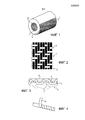
фиг. 2 - предпочтительный пример тканья фрикционного слоя фрикционной детали;FIG. 2 is a preferred example of weaving a friction layer of a friction part;
фиг. 3 - вид в сечении фрикционного слоя, выстланного упрочняющим слоем; иFIG. 3 is a sectional view of a friction layer lined with a reinforcing layer; and
фиг. 4 - упрощенная схема способа формирования фрикционной детали по фиг. с 1 по 3.FIG. 4 is a simplified diagram of a method for forming a friction part of FIG. 1 to 3.
Фрикционная деталь по настоящему изобретению содержит по существу фрикционный слой, имеющий свободную поверхность S, располагающуюся напротив прилегающего элемента, предпочтительно, фрикционная деталь дополнительно включает в себя упрочняющий слой вдоль фрикционного слоя, с противоположной стороны от поверхности трения, для увеличения механической прочности этого слоя.The friction part of the present invention contains a substantially friction layer having a free surface S located opposite the adjacent element, preferably the friction part further includes a reinforcing layer along the friction layer, on the opposite side from the friction surface, to increase the mechanical strength of this layer.
В примере по фиг. 1 фрикционная деталь является подшипником, предназначенным для приема в своем продольном отверстии не показанного вала. Альтернативно, речь может идти также о направляющей, принимающей поступательно перемещающийся стержень. Фрикционный слой вдоль поверхности трения (поэтому - внутренней поверхности) обозначен ссылочной позицией 2, в то время как упрочняющий слой обозначен ссылочной позицией 3. Этот слой 3 здесь имеет существенно бóльшую толщину, чем толщина фрикционного слоя; на самом деле, фрикционный слой имеет на практике толщину порядка, максимально, в несколько миллиметров (на практике - не более 3 мм), в то время как упрочняющий слой в зависимости от необходимости может иметь толщину в несколько миллиметров или даже в несколько сантиметров. Однако, само собой разумеется, что упрочняющий слой, если он присутствует, по сравнению с фрикционным слоем может быть любой относительной толщины.In the example of FIG. 1, the friction part is a bearing intended to receive a shaft not shown in its longitudinal bore. Alternatively, it may also be a guide receiving a translating rod. The friction layer along the friction surface (therefore, the inner surface) is indicated by 2, while the reinforcing layer is indicated by 3. This
Назначением фрикционного слоя является направление прилегающего элемента, то есть, вышеупомянутого вала при сохранении в течение как можно более длительного времени своего физического единства во время работы, включающей непрерывное воздействие рабочей температуры в по меньшей мере 250°С, которая временами может превышать 300°С (достигая, например, температуры порядка 320°С).The purpose of the friction layer is to direct the adjacent element, that is, the aforementioned shaft, while maintaining its physical unity for as long as possible during operation, including continuous exposure to the operating temperature of at least 250 ° C, which may sometimes exceed 300 ° C ( reaching, for example, a temperature of the order of 320 ° C).
Чтобы добиться этого, фрикционный слой выполнен из одного слоя ткани из нитей политетрафторэтилена (или PFTE), погруженных в матрицу, образованную из термоустойчивой смолы, имеющей температуру стеклования, большую, чем максимальная непрерывная рабочая температура, такая как по меньшей мере 250°С, и даже как можно более близкая к 300°С.To achieve this, the friction layer is made of a single fabric layer of polytetrafluoroethylene (or PFTE) filaments immersed in a matrix formed of a heat-resistant resin having a glass transition temperature higher than the maximum continuous operating temperature, such as at least 250 ° C, and even as close as possible to 300 ° C.
Здесь термин политетрафторэтилена или PFTE означает различные формы этого соединения, включая экспандированный вариант, известный под обозначением "ePTFE".As used herein, the term polytetrafluoroethylene or PFTE refers to various forms of this compound, including the expanded variant known as "ePTFE".
Форма плетения ткани, так сказать, относительная конфигурация составляющих ее нитей, выбрана, исходя из необходимости образования между различными нитями сквозных каналов, которые могут быть заполнены термоустойчивой смолой. На самом деле понятно, что поскольку PTFE практически не имеет никакой адгезии к другим материалам, погружение этой ткани в матрицу может быть выполнено лишь посредством перемешивания беспорядочных волокон, образованных смолой, заполняющей разнообразные существующие в ткани проходы, причем волокна у поверхности трения соединяются вдоль нитей из PFTE.The form of weaving of the fabric, so to speak, the relative configuration of its constituent threads, is selected on the basis of the need for the formation of through channels between the various threads, which can be filled with a heat-resistant resin. In fact, it is clear that since PTFE has practically no adhesion to other materials, immersion of this fabric in the matrix can only be done by mixing the disordered fibers formed by the resin filling the various passages existing in the fabric, and the fibers at the friction surface are connected along the threads of PFTE.
Понятно, что в зависимости от применения должен быть найден компромисс между сечением и количеством смоляных проходов через эту ткань, - чем более многочисленными и большими являются эти проходы, тем лучше выполняется погружение нитей PFTE, но тем меньшей становится доля части поверхности трения, которая образована нитями PFTE. И наоборот, - чем более высокой является доля поверхности трения, которая образована нитями PFTE, тем лучше «фрикционное поведение» фрикционной детали, но тем меньшей является погружение ткани в матрицу.It is clear that, depending on the application, a compromise must be found between the cross section and the number of resin passes through this fabric - the more numerous and large these passes are, the better the immersion of the PFTE threads is, but the smaller the fraction of the part of the friction surface that is formed by the threads PFTE. And vice versa, the higher the fraction of the friction surface that is formed by PFTE threads, the better the “frictional behavior” of the friction part, but the lower the immersion of the fabric in the matrix.
По-видимому, желательно, чтобы проход для смолы имелся у каждого переплетения уточных нитей и нитей основы.Apparently, it is desirable that a passage for resin be present at each weave of weft threads and warp threads.
Среди современных видов переплетений саржевое переплетение, а именно - саржевое переплетение 2/2, образованное переплетением пар уточных нитей и пар нитей основы, позволяет обеспечить образование между нитями сетки каналов, заполненных смолой достаточно плотно для обеспечения хорошего сцепления ткани, несмотря на отсутствие адгезии между нитями и смолой, создавая для прилегающего элемента значительную поверхность, образованную из PFTE.Among modern types of weave, twill weave, namely 2/2 twill weave, formed by weaving pairs of weft threads and pairs of warp threads, allows the formation of channels filled with resin between the threads of the mesh tight enough to ensure good adhesion of the fabric, despite the lack of adhesion between the threads and resin, creating for the adjacent element a significant surface formed from PFTE.
Такое саржевое переплетение 2/2 представлено на фигурах 2 и 3, на которых уточные нити обозначены ссылочной позицией 5, а нити основы обозначены ссылочной позицией 6, оставляя для прохождения смолы свободные зазоры 7, для того, чтобы гарантировать, что плетение не будет слишком плотным. Хорошие результаты были получены при саржевом переплетении 2/2.Such a
Еще большее преимущество получается тогда, когда каждая из уточных нитей и нитей основы образована одиночной нитью, образованной из волокон PTFE, связанных друг с другом посредством кручения, что означает, что эти одиночные нити, а значит и уточные и основные прядильные нити, представляют собой неровную поверхность, что способствует хорошему сцеплению ткани в матрице.An even greater advantage is obtained when each of the weft yarns and warp yarns are formed by a single yarn formed from PTFE fibers bonded to each other by torsion, which means that these single yarns, and hence the weft and warp yarn, are uneven surface, which contributes to a good adhesion of tissue in the matrix.
Хорошие результаты получаются при таком тканье мононитями, образованными из волокон со средним диаметром от 0,1 до 0,14 мм.Good results are obtained with such weaving with monofilaments formed from fibers with an average diameter of 0.1 to 0.14 mm.
Эти волокна, предпочтительно, имеют титраж в более чем 400 дтекс, преимущественно, - по меньшей мере 750 дтекс, при этом очень удовлетворительные результаты были получены с волокнами с титражом в 833 дтекс.These fibers preferably have a titre of over 400 dtex, preferably at least 750 dtex, and very satisfactory results were obtained with fibers with a titre of 833 dtex.
Как вариант, ткань образована из нитей, каждая из которых составлена из нескольких непрерывных отдельных нитей, или образована из коротких волокон, как в вышеописанном примере, в этом случае титраж отдельных нитей может быть меньшим, например, для двухнитевых прядильных нитей - порядка от 350 до 450 дтекс и даже менее. Ткание может быть выполнено из прядильных нитей с двумя или тремя составляющими с кручением или без оного.Alternatively, the fabric is formed from yarns, each of which is composed of several continuous separate yarns, or is formed from short fibers, as in the above example, in this case, the titration of individual yarns can be smaller, for example, for double-strand spinning yarns - from 350 to 450 dtex or less. Weaving can be made of spinning yarns with two or three components with or without torsion.
В соответствии с еще одним вариантом осуществления поверхность отдельных нитей преднамеренно загрублена, например, созданием микронасечек.In accordance with another embodiment, the surface of the individual threads is deliberately roughened, for example, by creating micro-notches.
Толщина ткани составляет по меньшей мере 0,30 мм или по меньшей мере 0,50 мм; возможны величины более миллиметра, это позволяет определить сечение предназначенных для использования нитей. Уточные прядильные нити и прядильные нити основы являются, что благоприятно, одинаковыми. Их сечение - в примерах, рассматриваемых на фиг. 2 и 3, представляет собой цилиндрическое сечение. В непоказанном варианте осуществления это сечение является прямоугольным, например, с коэффициентом формы (отношение между наибольшим размером и наименьшим размером), который, предпочтительно, равен по меньшей мере 2.The thickness of the fabric is at least 0.30 mm or at least 0.50 mm; Values of more than a millimeter are possible, this allows you to determine the cross section of the threads intended for use. Weft spinning yarns and warp spinning yarns are, favorably, the same. Their cross section is in the examples discussed in FIG. 2 and 3, is a cylindrical section. In an embodiment not shown, this section is rectangular, for example, with a shape factor (ratio between the largest size and the smallest size), which is preferably equal to at least 2.
Термоустойчивую смолу, предпочтительно, выбирают из термореактивных полиимидов, смол на основе цианата эфира или полиэфиркетонов (полиэфирэфиркетон - ПЭЭК, или полиэфиркетонкетон - ПЭКК и т. д.). Эти смолы имеют температуру стеклования по меньшей мере выше 280°С. Из термореактивных полиимидов можно назвать полибисмалеимид или BMI.The heat-resistant resin is preferably selected from thermosetting polyimides, resins based on ether cyanate or polyether ketones (polyetheretherketone-PEEK, or polyetherketone-PEKK, etc.). These resins have a glass transition temperature of at least above 280 ° C. Of the thermosetting polyimides, polybismaleimide or BMI may be mentioned.
Не представляется правильным добавление наполнителя в термоустойчивую смолу.It does not seem correct to add filler to a heat-resistant resin.
Поскольку упрочняющий слой, если он присутствует, во время работы предназначен для того, чтобы обеспечивать сохранение формы фрикционного слоя, несмотря на приложенное давление между фрикционным элементом и прилегающим элементом, в том числе и при высокой температуре, понятно, что благоприятным является тот факт, что упрочняющий слой выполнен из материала, имеющего очень низкий коэффициент теплового расширения, как правило, максимум 13⋅10-6 К-1 (что соответствует стали); специалист в данной области будет в состоянии определить необходимую геометрию и состав этого упрочняющего слоя. В частности, речь может идти, предпочтительно, о нитях или углеродных волокнах из, стекла или арамида, отдельных или собранных в ткань (иногда называемых ровницей)Since the reinforcing layer, if present, during operation is designed to maintain the shape of the friction layer, despite the applied pressure between the friction element and the adjacent element, including at high temperature, it is clear that the fact that the reinforcing layer is made of a material having a very low coefficient of thermal expansion, as a rule, a maximum of 13⋅10 -6 K -1 (which corresponds to steel); one skilled in the art will be able to determine the necessary geometry and composition of this reinforcing layer. In particular, it can preferably be yarn or carbon fibers of glass, or aramid, single or assembled into fabric (sometimes called roving)
Ткань фрикционного слоя, предпочтительно, выполнена в виде тесьмы, что наделяет ее большой свободой конфигурирования в соответствии с используемым фрикционным слоем, используя при необходимости преформу, профиль которой является реверсивным по отношению к форме поверхности трения, которую требуется получить. Ширина ленты тесьмы может быть выбрана в зависимости от необходимости, преимущественно, она выбирается величиной между 5 мм и 2 м, например, между 1 см и 10 см, предпочтительно, - между 1,5 см и 3 см.The fabric of the friction layer is preferably made in the form of braid, which gives it great freedom of configuration in accordance with the used friction layer, using, if necessary, a preform whose profile is reversible with respect to the shape of the friction surface to be obtained. The width of the ribbon tape can be selected depending on the need, mainly, it is selected between 5 mm and 2 m, for example, between 1 cm and 10 cm, preferably between 1.5 cm and 3 cm.
В том вышеупомянутом случае, когда фрикционной деталью является подшипник, его изготовление может начинаться с намотки такой ленты ткани на бобину, внешний диаметр которой равен внутреннему диаметру изготавливаемого подшипника, при этом ленту наматывают по винтовой линии таким образом, чтобы обеспечить контакт между кромками образованных на бобине последовательных витков ткани (см. фиг. 4). Понятно, что ширина ленты 10 обуславливает наклон уточных прядильных нитей и прядильных нитей основы по отношению к оси будущего подшипника. Действительно, уточные нити и нити основы расположены, соответственно, продольно и поперечно ленте ткани.In the aforementioned case, when the friction part is a bearing, its manufacture can begin by winding such a fabric ribbon onto a bobbin, the outer diameter of which is equal to the internal diameter of the bearing being manufactured, while the ribbon is wound along a helical line so as to ensure contact between the edges formed on the bobbin successive turns of fabric (see Fig. 4). It is clear that the width of the
Понятно, что непрерывность и уточных нитей, и нитей основы во фрикционном слое, способствует поддержанию высокой целостности подшипника в течение его срока службы, в этом смысле благоприятным является наклон этих прядильных нитей относительно продольной оси подшипника в диапазоне от 40° до 60°. В случае намотки такой ленты вплотную по кромкам, а также при намотке более одной ленты ткани (и не из одной нити), предпочтительно, чтобы намотка следовала под углом, заключенным между 65° и 89°.It is understood that the continuity of both weft and warp yarns in the friction layer helps to maintain high integrity of the bearing during its service life, in this sense, the inclination of these spinning threads relative to the longitudinal axis of the bearing in the range from 40 ° to 60 ° is favorable. In the case of winding such a tape closely along the edges, as well as when winding more than one tape of fabric (and not from one thread), it is preferable that the winding follows at an angle between 65 ° and 89 °.
Фрикционный слой может быть образован намоткой нити из углерода или из стекла, или же из другого приемлемого материала с углом наклона, который может быть любым. При намотке прядильных нитей оптимальный угол, по-видимому, заключен между 40° и 60°, но этот угол может изменяться в зависимости от применения, а также от требуемых механических характеристик.The friction layer can be formed by winding filaments of carbon or glass, or of another suitable material with an angle of inclination, which can be any. When winding the spinning yarns, the optimal angle is apparently between 40 ° and 60 °, but this angle can vary depending on the application, as well as on the required mechanical characteristics.
Лента ткани, с одной стороны, и нить упрочняющего слоя, с другой стороны, предпочтительно, предварительно пропитаны в термоустойчивой смоле, однако понятно, что если упрочняющий слой образован с использованием той же самой смолы, что и фрикционный слой, то последующая термообработка может способствовать слипанию матриц одна с другой.The fabric tape, on the one hand, and the thread of the reinforcing layer, on the other hand, are preferably pre-impregnated in a heat-resistant resin, however, it is clear that if the reinforcing layer is formed using the same resin as the friction layer, subsequent heat treatment can promote adhesion matrices with one another.
Вместо образования намотанной ленты ткань из PTFE может быть сформирована в виде плетеной трубчатой оболочки.Instead of forming a wound tape, PTFE fabric can be formed into a woven tubular sheath.
Легко понятно, что для элемента типа направляющей фрикционный слой может быть образован просто креплением вышеупомянутой ткани к подстилающему его упрочняющему слою.It is readily understood that for an element such as a guide, the friction layer can be formed simply by attaching the aforementioned fabric to the reinforcing layer underlying it.
В качестве примера, подшипник трения был изготовлен нижеописанным образом.As an example, a friction bearing was manufactured as described below.
Была выбрана ткань из PTFE толщиной 0,3 мм с саржевым переплетением 2/2 в виде ленты шириной 3 см. Эта лента была погружена в пропиточную ванну, поддерживаемую при температуре 110°С, содержащую термоустойчивую смолу типа полибисмалеимид (BMI), имеющую температуру стеклования в 285°С.A 0.3 mm thick PTFE fabric with 2/2 twill weave was selected in the form of a 3 cm wide tape. This tape was immersed in an impregnation bath maintained at a temperature of 110 ° C containing a heat-resistant polybismaleimide (BMI) resin having a glass transition temperature at 285 ° C.
Эта пропитанная лента была намотана на бобину с обеспечением покрытия всей поверхности бобины без перекрытия последовательных витков, то есть, таким образом, чтобы при этом по всей поверхности бобины сформировался единый непрерывный слой, который предназначен для создания подшипника (или множества подшипников). Предпочтительно, чтобы бобина при этом также поддерживалась при температуре пропиточной ванны.This impregnated tape was wound on a bobbin to ensure that the entire surface of the bobbin was covered without overlapping successive turns, i.e., so that a single continuous layer was formed over the entire surface of the bobbin, which is intended to create a bearing (or multiple bearings). Preferably, the bobbin is also maintained at the temperature of the impregnation bath.
Затем производят намотку волокна из эпоксидного стекла, предварительно пропитанного в той же самой смоле (речь идет об отдельных стеклянных нитях типа ровница)Then the fiber is made from epoxy glass, previously impregnated in the same resin (we are talking about individual glass threads of the roving type)
Последующий цикл полимеризации включает в себя 4-часовую выдержку (возможна бóльшая продолжительность) при 170°С, формовку, дополнительную 4-часовую термическую выдержку (возможна бóльшая продолжительность) при температуре между 230°С и 250°С.The subsequent polymerization cycle includes a 4-hour exposure (longer duration possible) at 170 ° С, molding, an additional 4-hour thermal aging (longer period possible) at a temperature between 230 ° С and 250 ° С.
Было найдено, что трудно нарезать волокна PTFE при последующем процессе механической обработки, что подтверждает высокое общее сопротивление на износ.It was found that it is difficult to cut the PTFE fibers in the subsequent machining process, which confirms the high total wear resistance.
Трибологические испытания проводились при следующих условиях:Tribological tests were carried out under the following conditions:
- амплитуда колебаний оси: 100°- amplitude of axis oscillations: 100 °
- проецированное давление: 80 МПа;- projected pressure: 80 MPa;
- средняя скорость: 8 мм/с;- average speed: 8 mm / s;
- среднее PV (давление×скорость): 0,64 МПа⋅м/с;- average PV (pressure × speed): 0.64 MPa⋅m / s;
- исходный зазор вал/подшипник: между 0,1 и 0,2 мм;- initial shaft / bearing clearance: between 0.1 and 0.2 mm;
- размеры подшипника: ∅внутр. 30 × ∅внешн. 36 × шир. 20;- bearing dimensions: ∅inner. 30 × External 36 × wide twenty;
- начальная смазка: отсутствует;- initial lubrication: none;
- прилегающая ось в испытательных конфигурациях: 16NC6 с цементированной термообработкой;- adjacent axis in test configurations: 16NC6 with cemented heat treatment;
- продолжительность испытания максимальная: 1 месяц (350.000 циклов);- maximum test duration: 1 month (350,000 cycles);
- окружающая температура.- ambient temperature.
В то время как при работе с известным подшипником (образованным основой из полиэфирной ткани, покрытой пропитанной PTFE смолой, или из ткани, составленной прядильными нитями из полиэфира и прядильными нитями из PTFE с максимальным содержанием PTFE по меньшей мере 50%) наблюдалось увеличение коэффициента трения до 0,04 и даже до 0,08, оказалось, что коэффициент трения подшипника по данному изобретению в течение 350.000 циклов оставался по существу постоянным и равным всего лишь 0,02.While when working with a known bearing (formed from a base made of polyester fabric coated with PTFE-impregnated resin, or from a fabric composed of polyester spinning yarns and PTFE spinning yarns with a maximum PTFE content of at least 50%), the friction coefficient increased to 0.04 and even up to 0.08, it turned out that the coefficient of friction of the bearing according to this invention for 350,000 cycles remained essentially constant and equal to only 0.02.
При контроле температуры в центре оси прилегающей части было найдено, что эта температура при использовании известного подшипника возрастала почти до 50°С или даже до 60°С, а при использовании подшипника в соответствии с изобретением эта температура оставалась ниже 40°С, что отражает тот факт, что энергия, подлежащая отводу при использовании подшипника по данному изобретению, меньше, чем энергия, выделяемая с известным подшипником.When controlling the temperature in the center of the axis of the adjacent part, it was found that this temperature when using a known bearing increased to almost 50 ° C or even 60 ° C, and when using the bearing in accordance with the invention, this temperature remained below 40 ° C, which reflects that the fact that the energy to be removed when using the bearing of this invention is less than the energy released with a known bearing.
Однако был констатирован общий износ подшипника по настоящему изобретению, который был больше, чем износ известного подшипника, в то время как прилегающий элемент был изношен очень мало, хотя можно предположить, что этот износ был всего лишь кажущимся, отражающим, на самом деле, существование явления крошения фрикционного слоя под воздействием приложенного контактного давления.However, the total wear of the bearing of the present invention was found to be greater than the wear of the known bearing, while the adjacent element was worn very little, although it can be assumed that this wear was only apparent, reflecting, in fact, the existence of the phenomenon crumbling of the friction layer under the influence of applied contact pressure.
Кроме того, подшипник по настоящему изобретению был испытан при следующих условиях:In addition, the bearing of the present invention was tested under the following conditions:
- амплитуда колебаний оси: 100°;- amplitude of axis oscillations: 100 °;
- проецированное давление: 80 МПа;- projected pressure: 80 MPa;
- средняя скорость: 8 мм/с;- average speed: 8 mm / s;
- среднее PV (давление×скорость): 0,64 МПа⋅м/с;- average PV (pressure × speed): 0.64 MPa⋅m / s;
- исходный зазор вал/подшипник: между 0,1 и 0,2 мм;- initial shaft / bearing clearance: between 0.1 and 0.2 mm;
- размеры подшипника: ∅внутр. 30 × ∅внешн. 36 × шир. 20;- bearing dimensions: ∅inner. 30 × External 36 × wide twenty;
- начальная смазка: отсутствует;- initial lubrication: none;
- прилегающая ось в испытательных конфигурациях: 16NC6 с цементирующей термообработкой;- adjoining axis in test configurations: 16NC6 with cementitious heat treatment;
- продолжительность испытания максимальная: 1 месяц (350.000 циклов);- maximum test duration: 1 month (350,000 cycles);
- изменение температуры - от 50°С до 280°С (окружающая температура) - было трудно поддерживать температуру постоянной во время подшипников температуры2).- temperature change - from 50 ° C to 280 ° C (ambient temperature) - it was difficult to keep the temperature constant during temperature bearings 2) .
Оказалось, что коэффициент трения, несмотря на переходы температуры до 280°С, оставался по существу постоянным.It turned out that the coefficient of friction, despite temperature transitions up to 280 ° C, remained essentially constant.
Эти испытания подтвердили, что подшипник в соответствии с изобретением прекрасно сочетает в себе очень низкий температурный коэффициент и высокое сопротивление температурам, превышающим 250°С, в диапазоне 250°С-280°С.These tests confirmed that the bearing in accordance with the invention perfectly combines a very low temperature coefficient and high resistance to temperatures in excess of 250 ° C, in the range of 250 ° C-280 ° C.
Claims (11)
Applications Claiming Priority (3)
| Application Number | Priority Date | Filing Date | Title |
|---|---|---|---|
| FR1456836A FR3023880B1 (en) | 2014-07-16 | 2014-07-16 | AUTOLUBRICATING FRICTION COMPOSITE PIECE |
| FR1456836 | 2014-07-16 | ||
| PCT/FR2015/051765 WO2016009124A1 (en) | 2014-07-16 | 2015-06-29 | Self-lubricating composite friction part |
Publications (3)
| Publication Number | Publication Date |
|---|---|
| RU2017104855A3 RU2017104855A3 (en) | 2018-08-16 |
| RU2017104855A RU2017104855A (en) | 2018-08-16 |
| RU2675156C2 true RU2675156C2 (en) | 2018-12-17 |
Family
ID=51519088
Family Applications (1)
| Application Number | Title | Priority Date | Filing Date |
|---|---|---|---|
| RU2017104855A RU2675156C2 (en) | 2014-07-16 | 2015-06-29 | Self-lubricating friction composite part |
Country Status (18)
| Country | Link |
|---|---|
| US (2) | US10900522B2 (en) |
| EP (1) | EP3169907B1 (en) |
| JP (3) | JP2017523360A (en) |
| KR (1) | KR102041692B1 (en) |
| CN (1) | CN106662142B (en) |
| AU (1) | AU2015288999B2 (en) |
| BR (1) | BR112017000265B1 (en) |
| CA (1) | CA2954579C (en) |
| DK (1) | DK3169907T3 (en) |
| ES (1) | ES2906616T3 (en) |
| FR (1) | FR3023880B1 (en) |
| HU (1) | HUE057953T2 (en) |
| MX (1) | MX2017000703A (en) |
| PL (1) | PL3169907T3 (en) |
| PT (1) | PT3169907T (en) |
| RU (1) | RU2675156C2 (en) |
| TW (1) | TWI698593B (en) |
| WO (1) | WO2016009124A1 (en) |
Families Citing this family (8)
| Publication number | Priority date | Publication date | Assignee | Title |
|---|---|---|---|---|
| FR2997146B1 (en) * | 2012-10-22 | 2014-11-21 | Hydromecanique & Frottement | SELF-LUBRICATING JOINT ELEMENT OPERATING IN HIGH DYNAMIC LOADS |
| FR3023880B1 (en) * | 2014-07-16 | 2017-05-26 | Hydromecanique & Frottement | AUTOLUBRICATING FRICTION COMPOSITE PIECE |
| DE102014220375A1 (en) * | 2014-10-08 | 2016-04-28 | Aktiebolaget Skf | bearing bracket |
| US11644064B2 (en) * | 2017-02-24 | 2023-05-09 | Vibracoustic Se | Bearing bush |
| US11221043B2 (en) * | 2019-07-29 | 2022-01-11 | Ovivo Inc. | Stabilizer bearing for mast of rotary distributor |
| CN111014531B (en) * | 2019-12-04 | 2021-08-27 | 上海交通大学 | Cold forging lubricating method based on net-shaped storage structure |
| JPWO2021124687A1 (en) * | 2019-12-20 | 2021-06-24 | ||
| CN111844968A (en) * | 2020-07-09 | 2020-10-30 | 中国科学院兰州化学物理研究所 | Preparation method of polyimide fiber/polytetrafluoroethylene fiber self-lubricating fabric liner material |
Citations (5)
| Publication number | Priority date | Publication date | Assignee | Title |
|---|---|---|---|---|
| US3825982A (en) * | 1972-01-19 | 1974-07-30 | Skf Cie Applic Mecanique | Method of making low friction bearings and bearings made therefrom |
| US4111499A (en) * | 1975-03-31 | 1978-09-05 | The Heim Universal Corporation | Bearing assembly and liner |
| RU2215206C1 (en) * | 2002-06-24 | 2003-10-27 | Общество с ограниченной ответственностью "Борец" | Friction couple and impeller of immersed multiple-impeller centrifugal pump provided with friction couple |
| RU2420407C2 (en) * | 2004-09-24 | 2011-06-10 | Иточу Корпорейшн | Thin-layer laminates |
| FR2997146A1 (en) * | 2012-10-22 | 2014-04-25 | Hydromecanique & Frottement | SELF-LUBRICATING JOINT ELEMENT OPERATING IN HIGH DYNAMIC LOADS |
Family Cites Families (27)
| Publication number | Priority date | Publication date | Assignee | Title |
|---|---|---|---|---|
| US2804886A (en) | 1955-11-04 | 1957-09-03 | Charles S White | Low friction fabric material |
| US3458374A (en) * | 1965-12-15 | 1969-07-29 | Samuel M Shobert | Method of making a braided tubular bearing having a polytetrafluoroethylene liner |
| GB1156165A (en) | 1966-09-06 | 1969-06-25 | American Metal Prod | A Bearing Element and method for making same |
| US3804479A (en) | 1972-12-21 | 1974-04-16 | Rexnord Inc | Low friction fabric-lined bearings and improved fabric therefor |
| GB1439030A (en) | 1973-08-03 | 1976-06-09 | Shobert S M | Plastics bearing |
| US4006051A (en) * | 1974-02-21 | 1977-02-01 | New Hampshire Ball Bearings, Inc. | Method of preparing a low-friction laminate liner for bearings |
| JPS593259B2 (en) * | 1976-11-30 | 1984-01-23 | オイレス工業株式会社 | Method for manufacturing fluororesin interwoven fabric sliding members |
| GB2095170A (en) * | 1981-03-16 | 1982-09-29 | Gen Electric | Fibrous bearing material |
| US4358167A (en) * | 1981-05-26 | 1982-11-09 | The Torrington Company | Bearing element |
| GB2170279B (en) | 1985-01-30 | 1988-10-19 | Ampep Plc | Self-lubricating bearings |
| JPS61228122A (en) * | 1985-03-29 | 1986-10-11 | Nok Corp | Sliding material |
| JPH07113373B2 (en) * | 1986-01-20 | 1995-12-06 | キヤノン株式会社 | Slide rail |
| JPH0721318B2 (en) | 1990-05-16 | 1995-03-08 | 日本ピラー工業株式会社 | Polymer composite material |
| JP3544788B2 (en) * | 1995-06-28 | 2004-07-21 | 三井化学株式会社 | Linear polyamic acid, linear polyimide and thermosetting polyimide |
| US5952067A (en) * | 1996-12-02 | 1999-09-14 | A&P Technology, Inc. | Braided structure having uncrimped strands |
| JPH11293268A (en) * | 1998-04-08 | 1999-10-26 | Toray Ind Inc | Sliding member |
| US6264369B1 (en) * | 1999-01-29 | 2001-07-24 | General Electric Company | Variable vane seal and washer materials |
| DE19915348B4 (en) * | 1999-04-06 | 2019-06-27 | Schaeffler Technologies AG & Co. KG | bearings |
| JP3651336B2 (en) * | 1999-11-24 | 2005-05-25 | 東レ・デュポン株式会社 | Reinforcing fiber sheet |
| JP2005220486A (en) * | 2004-02-06 | 2005-08-18 | Toray Ind Inc | Fluorofiber union cloth and composite material |
| US8021051B2 (en) * | 2006-07-07 | 2011-09-20 | Federal-Mogul World Wide, Inc. | Sleeve bearing assembly and method of construction |
| US8152380B2 (en) * | 2006-07-07 | 2012-04-10 | Federal-Mogul World Wide, Inc. | Sleeve bearing assembly and method of construction |
| JP2009120984A (en) * | 2007-11-14 | 2009-06-04 | Toray Ind Inc | Fluoro-fiber spun yarn and method for producing the same |
| JP5249726B2 (en) * | 2008-11-17 | 2013-07-31 | オイレス工業株式会社 | Fiber reinforced resin composition for sliding member and laminated sliding member |
| JP5368341B2 (en) | 2010-02-25 | 2013-12-18 | 株式会社ニューギン | Game machine |
| JP2011190561A (en) * | 2010-03-16 | 2011-09-29 | Nihon Gore Kk | Method for producing fabric, and fabric |
| FR3023880B1 (en) * | 2014-07-16 | 2017-05-26 | Hydromecanique & Frottement | AUTOLUBRICATING FRICTION COMPOSITE PIECE |
-
2014
- 2014-07-16 FR FR1456836A patent/FR3023880B1/en active Active
-
2015
- 2015-06-29 DK DK15742354.2T patent/DK3169907T3/en active
- 2015-06-29 CN CN201580038528.0A patent/CN106662142B/en active Active
- 2015-06-29 PL PL15742354T patent/PL3169907T3/en unknown
- 2015-06-29 AU AU2015288999A patent/AU2015288999B2/en active Active
- 2015-06-29 ES ES15742354T patent/ES2906616T3/en active Active
- 2015-06-29 JP JP2017502265A patent/JP2017523360A/en active Pending
- 2015-06-29 WO PCT/FR2015/051765 patent/WO2016009124A1/en active Application Filing
- 2015-06-29 PT PT157423542T patent/PT3169907T/en unknown
- 2015-06-29 CA CA2954579A patent/CA2954579C/en active Active
- 2015-06-29 RU RU2017104855A patent/RU2675156C2/en active
- 2015-06-29 US US15/325,447 patent/US10900522B2/en active Active
- 2015-06-29 MX MX2017000703A patent/MX2017000703A/en unknown
- 2015-06-29 HU HUE15742354A patent/HUE057953T2/en unknown
- 2015-06-29 EP EP15742354.2A patent/EP3169907B1/en active Active
- 2015-06-29 KR KR1020177003919A patent/KR102041692B1/en active IP Right Grant
- 2015-06-29 BR BR112017000265-5A patent/BR112017000265B1/en active IP Right Grant
- 2015-07-15 TW TW104122920A patent/TWI698593B/en active
-
2020
- 2020-04-09 JP JP2020070188A patent/JP2020122575A/en active Pending
- 2020-12-31 US US17/247,945 patent/US11781594B2/en active Active
-
2023
- 2023-01-10 JP JP2023001488A patent/JP2023057079A/en active Pending
Patent Citations (5)
| Publication number | Priority date | Publication date | Assignee | Title |
|---|---|---|---|---|
| US3825982A (en) * | 1972-01-19 | 1974-07-30 | Skf Cie Applic Mecanique | Method of making low friction bearings and bearings made therefrom |
| US4111499A (en) * | 1975-03-31 | 1978-09-05 | The Heim Universal Corporation | Bearing assembly and liner |
| RU2215206C1 (en) * | 2002-06-24 | 2003-10-27 | Общество с ограниченной ответственностью "Борец" | Friction couple and impeller of immersed multiple-impeller centrifugal pump provided with friction couple |
| RU2420407C2 (en) * | 2004-09-24 | 2011-06-10 | Иточу Корпорейшн | Thin-layer laminates |
| FR2997146A1 (en) * | 2012-10-22 | 2014-04-25 | Hydromecanique & Frottement | SELF-LUBRICATING JOINT ELEMENT OPERATING IN HIGH DYNAMIC LOADS |
Also Published As
| Publication number | Publication date |
|---|---|
| US20210123478A1 (en) | 2021-04-29 |
| PL3169907T3 (en) | 2022-07-11 |
| MX2017000703A (en) | 2017-11-30 |
| RU2017104855A3 (en) | 2018-08-16 |
| KR20170034898A (en) | 2017-03-29 |
| JP2023057079A (en) | 2023-04-20 |
| CA2954579C (en) | 2019-05-14 |
| EP3169907A1 (en) | 2017-05-24 |
| FR3023880A1 (en) | 2016-01-22 |
| BR112017000265B1 (en) | 2021-08-10 |
| TW201612431A (en) | 2016-04-01 |
| JP2020122575A (en) | 2020-08-13 |
| RU2017104855A (en) | 2018-08-16 |
| ES2906616T3 (en) | 2022-04-19 |
| HUE057953T2 (en) | 2022-06-28 |
| CA2954579A1 (en) | 2016-01-21 |
| CN106662142A (en) | 2017-05-10 |
| WO2016009124A1 (en) | 2016-01-21 |
| BR112017000265A2 (en) | 2017-10-31 |
| TWI698593B (en) | 2020-07-11 |
| FR3023880B1 (en) | 2017-05-26 |
| DK3169907T3 (en) | 2022-03-07 |
| EP3169907B1 (en) | 2021-12-22 |
| US20170175812A1 (en) | 2017-06-22 |
| AU2015288999B2 (en) | 2018-11-08 |
| US11781594B2 (en) | 2023-10-10 |
| JP2017523360A (en) | 2017-08-17 |
| CN106662142B (en) | 2019-10-25 |
| AU2015288999A1 (en) | 2017-03-09 |
| KR102041692B1 (en) | 2019-11-06 |
| US10900522B2 (en) | 2021-01-26 |
| PT3169907T (en) | 2022-03-03 |
Similar Documents
| Publication | Publication Date | Title |
|---|---|---|
| RU2675156C2 (en) | Self-lubricating friction composite part | |
| US5631085A (en) | Compound yarn producing the sliding layer of plain bearings made of fiber-reinforced thermoplastics | |
| JP7017142B2 (en) | Self-lubricating woven fabrics and their production methods and applications | |
| JP2023057079A5 (en) | ||
| JP2008069973A (en) | Plastic sliding layer, and sliding element having the sliding layer | |
| US10619767B2 (en) | Tubular pipe with a composite holding strip | |
| JP2005220486A (en) | Fluorofiber union cloth and composite material | |
| CN105673695B (en) | Component comprising at least one sliding layer | |
| EP3101290A1 (en) | Curved sliding liner and curved sliding member | |
| CN113818120A (en) | High-modulus uniaxial glass fiber fabric | |
| JP2005220487A (en) | Fluorine fiber fabric and composite material | |
| CN107109287B (en) | Composite bearing with enhanced wear and machinability | |
| US3832255A (en) | Method of fabricating an improved plastic bearing | |
| CN111139653A (en) | Self-lubricating fabric and application thereof | |
| KR20050081493A (en) | A self-lubricating bearing | |
| CN101166918B (en) | Power transmission belt for transmitting high loads | |
| CN218711302U (en) | Woven cable with low friction coefficient | |
| JP2010090908A (en) | Manufacturing method of retainer for high-speed rotation roller bearing | |
| RU2569839C1 (en) | Multi-component complex reinforcing thread | |
| CN111981037A (en) | Bushing with improved wear resistance and sliding bearing comprising such a bushing | |
| CN115369539A (en) | Woven inhaul cable and manufacturing method thereof | |
| JP2010175012A (en) | High load transmission belt |