JP2020122575A - Self-lubricating composite friction part - Google Patents
Self-lubricating composite friction part Download PDFInfo
- Publication number
- JP2020122575A JP2020122575A JP2020070188A JP2020070188A JP2020122575A JP 2020122575 A JP2020122575 A JP 2020122575A JP 2020070188 A JP2020070188 A JP 2020070188A JP 2020070188 A JP2020070188 A JP 2020070188A JP 2020122575 A JP2020122575 A JP 2020122575A
- Authority
- JP
- Japan
- Prior art keywords
- fabric
- component
- resin
- friction
- weft
- Prior art date
- Legal status (The legal status is an assumption and is not a legal conclusion. Google has not performed a legal analysis and makes no representation as to the accuracy of the status listed.)
- Pending
Links
Images
Classifications
-
- F—MECHANICAL ENGINEERING; LIGHTING; HEATING; WEAPONS; BLASTING
- F16—ENGINEERING ELEMENTS AND UNITS; GENERAL MEASURES FOR PRODUCING AND MAINTAINING EFFECTIVE FUNCTIONING OF MACHINES OR INSTALLATIONS; THERMAL INSULATION IN GENERAL
- F16C—SHAFTS; FLEXIBLE SHAFTS; ELEMENTS OR CRANKSHAFT MECHANISMS; ROTARY BODIES OTHER THAN GEARING ELEMENTS; BEARINGS
- F16C33/00—Parts of bearings; Special methods for making bearings or parts thereof
- F16C33/02—Parts of sliding-contact bearings
- F16C33/04—Brasses; Bushes; Linings
- F16C33/20—Sliding surface consisting mainly of plastics
- F16C33/208—Methods of manufacture, e.g. shaping, applying coatings
-
- F—MECHANICAL ENGINEERING; LIGHTING; HEATING; WEAPONS; BLASTING
- F16—ENGINEERING ELEMENTS AND UNITS; GENERAL MEASURES FOR PRODUCING AND MAINTAINING EFFECTIVE FUNCTIONING OF MACHINES OR INSTALLATIONS; THERMAL INSULATION IN GENERAL
- F16C—SHAFTS; FLEXIBLE SHAFTS; ELEMENTS OR CRANKSHAFT MECHANISMS; ROTARY BODIES OTHER THAN GEARING ELEMENTS; BEARINGS
- F16C17/00—Sliding-contact bearings for exclusively rotary movement
- F16C17/02—Sliding-contact bearings for exclusively rotary movement for radial load only
-
- F—MECHANICAL ENGINEERING; LIGHTING; HEATING; WEAPONS; BLASTING
- F16—ENGINEERING ELEMENTS AND UNITS; GENERAL MEASURES FOR PRODUCING AND MAINTAINING EFFECTIVE FUNCTIONING OF MACHINES OR INSTALLATIONS; THERMAL INSULATION IN GENERAL
- F16C—SHAFTS; FLEXIBLE SHAFTS; ELEMENTS OR CRANKSHAFT MECHANISMS; ROTARY BODIES OTHER THAN GEARING ELEMENTS; BEARINGS
- F16C29/00—Bearings for parts moving only linearly
- F16C29/02—Sliding-contact bearings
-
- F—MECHANICAL ENGINEERING; LIGHTING; HEATING; WEAPONS; BLASTING
- F16—ENGINEERING ELEMENTS AND UNITS; GENERAL MEASURES FOR PRODUCING AND MAINTAINING EFFECTIVE FUNCTIONING OF MACHINES OR INSTALLATIONS; THERMAL INSULATION IN GENERAL
- F16C—SHAFTS; FLEXIBLE SHAFTS; ELEMENTS OR CRANKSHAFT MECHANISMS; ROTARY BODIES OTHER THAN GEARING ELEMENTS; BEARINGS
- F16C33/00—Parts of bearings; Special methods for making bearings or parts thereof
- F16C33/02—Parts of sliding-contact bearings
- F16C33/04—Brasses; Bushes; Linings
- F16C33/20—Sliding surface consisting mainly of plastics
-
- F—MECHANICAL ENGINEERING; LIGHTING; HEATING; WEAPONS; BLASTING
- F16—ENGINEERING ELEMENTS AND UNITS; GENERAL MEASURES FOR PRODUCING AND MAINTAINING EFFECTIVE FUNCTIONING OF MACHINES OR INSTALLATIONS; THERMAL INSULATION IN GENERAL
- F16C—SHAFTS; FLEXIBLE SHAFTS; ELEMENTS OR CRANKSHAFT MECHANISMS; ROTARY BODIES OTHER THAN GEARING ELEMENTS; BEARINGS
- F16C17/00—Sliding-contact bearings for exclusively rotary movement
- F16C17/12—Sliding-contact bearings for exclusively rotary movement characterised by features not related to the direction of the load
- F16C17/24—Sliding-contact bearings for exclusively rotary movement characterised by features not related to the direction of the load with devices affected by abnormal or undesired positions, e.g. for preventing overheating, for safety
- F16C17/243—Sliding-contact bearings for exclusively rotary movement characterised by features not related to the direction of the load with devices affected by abnormal or undesired positions, e.g. for preventing overheating, for safety related to temperature and heat, e.g. for preventing overheating
-
- F—MECHANICAL ENGINEERING; LIGHTING; HEATING; WEAPONS; BLASTING
- F16—ENGINEERING ELEMENTS AND UNITS; GENERAL MEASURES FOR PRODUCING AND MAINTAINING EFFECTIVE FUNCTIONING OF MACHINES OR INSTALLATIONS; THERMAL INSULATION IN GENERAL
- F16C—SHAFTS; FLEXIBLE SHAFTS; ELEMENTS OR CRANKSHAFT MECHANISMS; ROTARY BODIES OTHER THAN GEARING ELEMENTS; BEARINGS
- F16C2208/00—Plastics; Synthetic resins, e.g. rubbers
- F16C2208/20—Thermoplastic resins
- F16C2208/30—Fluoropolymers
- F16C2208/32—Polytetrafluorethylene [PTFE]
-
- F—MECHANICAL ENGINEERING; LIGHTING; HEATING; WEAPONS; BLASTING
- F16—ENGINEERING ELEMENTS AND UNITS; GENERAL MEASURES FOR PRODUCING AND MAINTAINING EFFECTIVE FUNCTIONING OF MACHINES OR INSTALLATIONS; THERMAL INSULATION IN GENERAL
- F16C—SHAFTS; FLEXIBLE SHAFTS; ELEMENTS OR CRANKSHAFT MECHANISMS; ROTARY BODIES OTHER THAN GEARING ELEMENTS; BEARINGS
- F16C2208/00—Plastics; Synthetic resins, e.g. rubbers
- F16C2208/20—Thermoplastic resins
- F16C2208/40—Imides, e.g. polyimide [PI], polyetherimide [PEI]
-
- F—MECHANICAL ENGINEERING; LIGHTING; HEATING; WEAPONS; BLASTING
- F16—ENGINEERING ELEMENTS AND UNITS; GENERAL MEASURES FOR PRODUCING AND MAINTAINING EFFECTIVE FUNCTIONING OF MACHINES OR INSTALLATIONS; THERMAL INSULATION IN GENERAL
- F16C—SHAFTS; FLEXIBLE SHAFTS; ELEMENTS OR CRANKSHAFT MECHANISMS; ROTARY BODIES OTHER THAN GEARING ELEMENTS; BEARINGS
- F16C2208/00—Plastics; Synthetic resins, e.g. rubbers
- F16C2208/80—Thermosetting resins
- F16C2208/82—Composites, i.e. fibre reinforced thermosetting resins
-
- F—MECHANICAL ENGINEERING; LIGHTING; HEATING; WEAPONS; BLASTING
- F16—ENGINEERING ELEMENTS AND UNITS; GENERAL MEASURES FOR PRODUCING AND MAINTAINING EFFECTIVE FUNCTIONING OF MACHINES OR INSTALLATIONS; THERMAL INSULATION IN GENERAL
- F16C—SHAFTS; FLEXIBLE SHAFTS; ELEMENTS OR CRANKSHAFT MECHANISMS; ROTARY BODIES OTHER THAN GEARING ELEMENTS; BEARINGS
- F16C2220/00—Shaping
- F16C2220/02—Shaping by casting
- F16C2220/08—Shaping by casting by compression-moulding
-
- F—MECHANICAL ENGINEERING; LIGHTING; HEATING; WEAPONS; BLASTING
- F16—ENGINEERING ELEMENTS AND UNITS; GENERAL MEASURES FOR PRODUCING AND MAINTAINING EFFECTIVE FUNCTIONING OF MACHINES OR INSTALLATIONS; THERMAL INSULATION IN GENERAL
- F16C—SHAFTS; FLEXIBLE SHAFTS; ELEMENTS OR CRANKSHAFT MECHANISMS; ROTARY BODIES OTHER THAN GEARING ELEMENTS; BEARINGS
- F16C2220/00—Shaping
- F16C2220/28—Shaping by winding impregnated fibres
Abstract
Description
本発明は、様々な用途向けの自滑性複合摩擦部品であって、対向した部品との間に潤滑剤を利用せず、したがって対向した部品との低い摩擦係数を有しかつ/あるいは250℃を超えかつ最高300℃までの範囲に至ることができまたは更には320℃をピークとすることもできる温度に関与する自滑性複合摩擦部品に関する。かかる摩擦部品は、特に、継手またはスライダであるのが良い。 The present invention is a self-lubricating composite friction component for a variety of applications that does not utilize a lubricant between opposing components and therefore has a low coefficient of friction with opposing components and/or 250°C. And self-lubricating composite friction parts involved in temperatures that can range up to 300° C. and even peak at 320° C. Such a friction part may especially be a joint or a slider.
この種の制約条件を満足させるため、機械部品の表面を、マトリックスを形成する樹脂で含浸した内張りで覆うことが既に提案されているが、これら覆いによっては高温での良好な性能と組み合わされた低い摩擦係数を得ることが可能ではない。 To meet this type of constraint, it has already been proposed to cover the surface of machine parts with a matrix-forming resin-impregnated lining, which combined with good performance at high temperatures. It is not possible to obtain a low coefficient of friction.
かくして、英国特許第1,439,030号明細書は、フルオロカーボン含有樹脂を含む低摩擦係数のストランドによって形成された隣り合うコードを織成することによって形成された摩擦層を有する特に軸受またはベアリング用の摩擦覆いを記載しており、これらコードの表面は、隆起した部分および窪んだ部分を含むでこぼこを有し、ストランドおよびコードは、プラスチック材料内に埋め込まれる。ストランドは、どのようなプラスチック材料にも化学的に結合しない材料、たとえばPTFEで作られた繊維によって形成されるが、これら繊維は、上述の覆い内に繋留され、PTFE繊維を綿のストランドと混ぜ合わせることができる。上述の実施例では、織物は、ガラス繊維の螺旋集成体によって螺旋状に境界付けられた状態で延び、この集成体は、エポキシまたはポリエステル樹脂内に埋め込まれる。ガラス繊維によって形成された層は、PTFEストランドによって形成された層よりも厚い。特にマトリックスとして用いられた樹脂の性状に起因して、かかる覆いは、作動中、200℃の温度にほとんど耐えることができないことが理解される。 Thus, British Patent 1,439,030 is particularly directed to bearings or bearings having a friction layer formed by weaving adjacent cords formed by strands of low friction coefficient containing fluorocarbon-containing resin. And the surface of these cords has bumps, including raised and recessed portions, the strands and cords being embedded in a plastic material. The strands are formed by fibers that are not chemically bonded to any plastic material, such as fibers made of PTFE, which are anchored in the above-mentioned wrapping to mix the PTFE fibers with the cotton strands. Can be matched. In the above-described embodiment, the fabric extends in a spiral bounded state by a spiral assembly of glass fibers, which assembly is embedded within an epoxy or polyester resin. The layer formed by glass fibers is thicker than the layer formed by PTFE strands. It is understood that such a cover can barely withstand a temperature of 200° C. during operation, especially due to the nature of the resin used as the matrix.
また、日本国特開平04−25669号公報では、PTFE繊維の表面を活性化して繊維をマトリックス内に固定し、このマトリックス内においてこれら繊維を多くともかろうじて5%である濃度で混ぜ合わされる。さらに、かかる構成によっても、高温で摩擦係数が低い場合に良好な機械的性能を得ることが可能ではない。 In JP 04-25669 A, the surface of PTFE fibers is activated to immobilize the fibers in a matrix, and the fibers are mixed in the matrix at a concentration of at most 5%. Furthermore, even with such a configuration, it is not possible to obtain good mechanical performance when the friction coefficient is low at high temperatures.
米国特許第2,804,886号明細書および同第3,804,479号明細書からのある特定の教示の繰り返しにより、テフロン(Teflon(登録商標))のフィラメントおよびダクロン(Dacron(登録商標))の付着性または粘着性フィラメントを含む別の形式の摩擦層が提案されており、これらフィラメントは、液体樹脂による良好な含浸を可能にするほど十分にルーズに織成され、この層は、樹脂を含浸させると共にガラス繊維を入れたストリップの巻回によって境界付けられる。材料中にたとえばダクロン(Dacron(登録商標))のような付着性フィラメントが存在していることは、作動中、覆いが200℃以上の温度に耐えることができないということを意味している。 By repeating certain teachings from US Pat. Nos. 2,804,886 and 3,804,479, Teflon® filaments and Dacron® are available. ), another type of friction layer has been proposed, including adhesive or tacky filaments, which filaments are woven sufficiently loose to allow good impregnation with a liquid resin, which layer is And bounded by winding a strip of glass fiber. The presence of adherent filaments, such as Dacron® in the material, means that during operation, the shroud cannot withstand temperatures above 200°C.
米国特許第4,666,318号明細書は、PTFEを含むプラスチック材料により形成され、そして0.050ミクロンCLA以下の粗さおよび1000VPN以上の硬さを有する対向部品と協働する航空分野(低圧および低振幅)において極めて特定の用途向きの自滑性覆いを開示している。 U.S. Pat. No. 4,666,318 describes aeronautics (low pressure And low amplitude) for a very specific application.
理解されるように、低摩擦係数と、良好な機械的性能(特に、良好な引き裂き強さ)と、250℃〜300℃(または更には、過渡的作動の際には最高320℃まで)の作動温度まで良好な摩擦特性および機械的特性を保持する能力とを組み合わせた摩擦覆いを構成することは、250℃を超える状態での良好な機械的性能を保持する一方で、この温度しきい値を超える温度での付着性を含む満足の行く付着性を示す樹脂と、特に低い係数を備え、したがってアプリオリにこの樹脂への付着性が非常に高くはない内張り要素とを組み合わせることが、工業的に受容可能な条件下で、かつリーズナブルなコストで、実現できるということを意味している。 As can be seen, low coefficient of friction, good mechanical performance (especially good tear strength), and 250°C to 300°C (or even up to 320°C during transient operation). Constructing a friction shroud that combines good frictional properties up to operating temperature and the ability to retain mechanical properties retains good mechanical performance at temperatures above 250°C while maintaining this temperature threshold. It is commercially viable to combine a resin that exhibits satisfactory adhesion, including adhesion at temperatures above, with a lining element that has a particularly low coefficient and therefore does not have very high adhesion to this resin. It means that it can be realized under reasonable conditions and at a reasonable cost.
本発明の目的は、この要望に応えるということにある。 The object of the present invention is to meet this need.
この目的のため、本発明は、作動中、少なくとも250℃に等しい温度を受けることができる自滑性複合摩擦部品であって、部品は、摩擦面に沿って、ポリテトラフルオロエチレンのよこ糸およびたて糸で形成された織物の単一の層を有し、織物は、少なくとも250℃に等しいガラス転移温度を有する熱安定性樹脂で含浸処理されていることを特徴とする部品を提案する。 To this end, the present invention is a self-lubricating composite friction part capable of undergoing a temperature equal to at least 250° C. during operation, the part comprising a polytetrafluoroethylene weft and warp along a friction surface. We propose a component, characterized in that it has a single layer of fabric formed in accordance with claim 1, wherein the fabric is impregnated with a thermostable resin having a glass transition temperature equal to at least 250°C.
注目できることとして、既に提案された解決策とは異なり、本発明は、織物の単一の層の利用を教示し、この織物のたて糸およびよこ糸は、全て、ポリテトラフルオロエチレン(PTFE)で作られる。かくして、本発明は、織物を構成するストランド(より最近において知られている解決策では数個の薄い層を想定する傾向のあったストランド)の断面を増大させることを推奨しており、樹脂による良好な繋留を促進すると共に、PTFEのストランドだけを使用するようにしている。(より最近において知られている解決策では同一の織物内においてPTFEのストランドと樹脂との良好な付着性を有する異なるストランドを組み合わせる傾向があった。)事実、部品の表面を保護する層中に、PTFEの織物の単一の層だけを用いるということにより、この保護層の厚さ全体にわたってストランドの連続性が与えられている場合、引き裂き強さを増大させる一方で、織物のストランド相互間に残っている空間により樹脂中へのこの層の良好な繋留を促進するという利点が得られる。 Notably, unlike the previously proposed solution, the present invention teaches the use of a single layer of fabric, the warp and weft of which are all made of polytetrafluoroethylene (PTFE). .. Thus, the present invention recommends increasing the cross-section of the strands that make up the fabric (strands that tended to assume several thin layers in the more recently known solutions), and It promotes good anchorage and uses only PTFE strands. (More recently known solutions have tended to combine PTFE strands with different strands having good adhesion to the resin within the same fabric.) In fact, in the layer that protects the surface of the part , By using only a single layer of PTFE woven fabric, increasing the tear strength, while providing a continuity of strands throughout the thickness of this protective layer, while increasing the tear strength between the woven fabric strands. The remaining space has the advantage of promoting good anchoring of this layer in the resin.
かかる織物は、自滑性であると言える。 Such a fabric can be said to be self-lubricating.
本発明の有利な特徴によれば、
・織物は、対をなすよこ糸と対をなすたて糸の交差によって形成された織り方(ウィーブ)であり、この織物は、特に、2/2綾織物であるのが良く、
・よこ糸またはたて糸は、互いに結合された短繊維によって形成され、
・織物は、少なくとも0.10mm、有利には少なくとも0.30mm、好ましくは少なくとも0.50mmの厚さを有し、
・よこ糸およびたて糸は、少なくとも100デシテックス、好ましくは少なくとも400デシテックスの番手を有し、
・樹脂は、熱硬化性ポリイミドであり、
・部品は、摩擦面に対向した織物を境界付ける補強層を更に有し、補強層は、織物と同一の樹脂で含浸処理され、
・部品は、種々の考えられる用途の中でベアリングまたは案内レールを構成する。
According to an advantageous feature of the invention,
The woven fabric is a weave (weave) formed by the intersection of a pair of weft yarns and a pair of warp yarns, and the woven fabric is particularly preferably a 2/2 twill fabric,
The weft or warp threads being formed by short fibers joined together,
The fabric has a thickness of at least 0.10 mm, advantageously at least 0.30 mm, preferably at least 0.50 mm,
The weft and warp yarns have a count of at least 100 decitex, preferably at least 400 decitex,
-The resin is thermosetting polyimide,
The component further comprises a reinforcing layer that bounds the fabric facing the friction surface, the reinforcing layer being impregnated with the same resin as the fabric,
-The parts constitute bearings or guide rails in various possible applications.
本発明の製品は、作動中、250℃を超え、途切れなく最高300℃までの範囲にあり、更には320℃でピークを迎えることができる温度で自己潤滑性を示すことができる一方で未処理のPTFE(添加物なしまたは内張りなし)の摩擦係数と同等の極めて低い摩擦係数(0.01〜0.2)を示すが、40N/mm2を超える荷重に対して耐性があるという利点を示している。 The product of the present invention is capable of exhibiting self-lubricating properties at temperatures above 250° C. and up to 300° C. without interruption during operation and even peaking at 320° C. while untreated. Has a very low coefficient of friction (0.01-0.2) equivalent to that of PTFE (without additives or lining), but with the advantage of being resistant to loads above 40 N/mm 2. ing.
類推により、本発明は、上述した形式の自滑性複合摩擦部品の製造方法であって、全てがポリテトラフルオロエチレンで構成されたよこ糸およびたて糸によって形成されている織物のストリップを、ストリップが各ターン後にそれ自体端と端を付き合わせた状態になるような巻回角度に従ってマンドレル上に螺旋状に巻き付けることによって織物の層を形成し、織物は、少なくとも250℃のガラス転移温度を有する熱安定性樹脂で含浸処理されていることを特徴とする方法を提案する。この樹脂は、有利には、熱硬化性ポリイミドである。 By analogy, the present invention is a method of making a self-lubricating composite friction part of the type described above, wherein each strip comprises a strip of fabric formed of weft and warp yarns all made of polytetrafluoroethylene. A layer of fabric is formed by helically wrapping on a mandrel according to a winding angle such that after turn it is end-to-end, the fabric is thermally stable with a glass transition temperature of at least 250°C. A method characterized by being impregnated with a functional resin is proposed. This resin is advantageously a thermosetting polyimide.
本発明の目的、特徴および利点は、以下の説明、添付の図面を参照して非限定的な例示の実施形態により与えられる以下の説明から明らかになろう。 Objects, features and advantages of the present invention will be apparent from the following description, the following description provided by non-limiting exemplary embodiments with reference to the accompanying drawings.
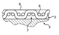
本発明の摩擦部品は、本質的に、対向する部品と向かい合うようになった自由表面Sを備えた摩擦層を有し、有利には、この摩擦部品は、この摩擦層の機械的性能を強化するために摩擦面と対向した摩擦層を境界付ける補強層をさらに有する。 The friction part of the invention essentially comprises a friction layer with a free surface S adapted to face the opposite part, advantageously the friction part enhances the mechanical performance of the friction layer. In order to do so, it further has a reinforcing layer that bounds the friction layer facing the friction surface.
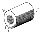
図1の実施例では、摩擦部品は、ベアリング1であり、このベアリングは、その長手方向ボア1A内にシャフト(図示せず)を受け入れるようになっている。変形例では、摩擦部品は、並進運動状態にあるロッドを受け入れるスライダであっても良い。摩擦面(したがって、内面)と境界付ける摩擦層は、参照符号2で示され、補強層は、参照符号3で示されている。この層3は、この場合、摩擦層よりも実質的に厚い厚さを有し、事実、要件に応じて、摩擦層は、実際には、多くとも数ミリメートル(実際には3mm以下)のオーダーの厚さを有し、補強層は、厚さが数ミリメートルまたは更には数センチメートルであるのが良い。しかしながら、言うまでもないこととして、補強層は、これが存在する場合、摩擦層に対して任意の相対的な厚さを有しても良い。
In the embodiment of Figure 1, the friction component is a bearing 1, which is adapted to receive a shaft (not shown) in its
摩擦層の機能は、摩擦を可能な限り小さくした状態で上述したシャフトである対向した部品を案内する一方で、できるだけ長い時間にわたって、途切れなく少なくとも250℃の作動温度での作動を含むとともに300℃を超える温度(たとえば、最高320℃のオーダーまでの温度)をピーク温度とする作動を含む作動中、その物理的健全性を保持することにある。 The function of the friction layer is to guide the opposite parts, which are the above-mentioned shafts, with the friction as low as possible, while at the same time operating at an operating temperature of at least 250° C. for as long a time as possible and at 300° C. To maintain its physical integrity during operation, including operations with peak temperatures above (eg, temperatures up to the order of 320° C.).
これを行うため、摩擦層は、最大連続作動温度を超え、したがって、少なくとも250℃または更には300℃にできるだけ近い温度を超えるガラス転移温度を有する熱安定性樹脂によって形成されているマトリックスで被覆したポリテトラフルオロエチレン(即ち、PTFE)で作られているストランド(または糸)の織物の単一の層から成る。 To do this, the friction layer is coated with a matrix which is formed by a thermostable resin which has a glass transition temperature above the maximum continuous operating temperature and therefore above at least 250° C. or even as close as possible to 300° C. It consists of a single layer of a woven fabric of strands (or threads) made of polytetrafluoroethylene (ie PTFE).
ポリテトラフルオロエチレン、すなわちPTFEの概念は、この場合、このコンパウンドの種々の形態を示しており、かかる形態としては、“ePTFE”と呼ばれている発泡型が挙げられる。 The concept of polytetrafluoroethylene, or PTFE, in this case refers to various forms of this compound, such as the foamed form called "ePTFE".
織物の織り方、すなわち、この織物を構成しているストランドの相対的構成は、種々のストランド相互間に熱安定性樹脂を充填することができるフローチャネルを形成するよう選択される。事実、理解されるように、PTFEは、事実上、他の物質との付着性を備えていないので、マトリックス内への織物の繋留は、織物を貫通して存在する種々のフローチャネルを満たす樹脂によって構成された不定形のフィラメントを絡み合わせることによってしか実施できず、かかるフィラメントは、摩擦面の近くに位置するPTFEのストランドに沿って互いに連結される。 The weave of the fabric, i.e., the relative composition of the strands that make up the fabric, is selected to form flow channels that can be filled with thermostable resin between the various strands. In fact, as can be seen, PTFE is virtually non-adhesive to other substances, so the anchoring of the fabric within the matrix results in the resin filling the various flow channels present through the fabric. It can only be carried out by intertwining indefinite filaments constituted by, such filaments being connected to each other along the strands of PTFE located near the friction surface.
理解されるように、用途に応じて、織物を貫通する樹脂フローチャネルの断面と本数に関し、妥協点が見出されるべきであり、これらのフローチャネルの本数が多ければ多く、しかも幅が広ければ広いほど、PTFE内のストランドの繋留具合がそれだけ一層良好になるが、PTFEのストランドにより形成される摩擦面の割合がそれだけ一層小さくなる。これとは逆に、PTFE内のストランドで形成される摩擦面の割合が大きければ大きいほど、摩擦部品の摩擦強度がそれだけ一層良好になるが、マトリックス中の織物の繋留具合がそれだけ一層弱くなる。 As will be appreciated, depending on the application, a compromise should be found in the cross section and number of resin flow channels through the fabric, the greater the number of these flow channels and the greater the width. The better the anchoring of the strands in the PTFE, the smaller the proportion of the friction surface formed by the PTFE strands. On the contrary, the greater the proportion of the friction surfaces formed by the strands in the PTFE, the better the frictional strength of the friction part, but the weaker the anchoring of the fabric in the matrix.
よこ糸とたて糸の各交差部のところに樹脂のためのフローチャネルが存在することは、望ましいと考えられる。 The presence of flow channels for the resin at each intersection of the weft and warp threads is considered desirable.
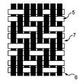
一般的な織り方のうちで、綾織物、より正確に言えば対をなすよこ糸と対をなすたて糸の織成によって形成された2/2綾織物は、ネットワークのストランド相互間に樹脂で満たされたチャネルの構成を可能にし、樹脂は、ストランドと樹脂との間に接着性がないにもかかわらず織物の良好な繋留具合を保障するのに十分高密度であり、他方対向した部品にPTFEにより形成された相当広い表面を与えるように思われる。 Among the common weaves, twill fabrics, or more precisely, 2/2 twill fabrics formed by weaving paired weft yarns and paired warp yarns, are filled with resin between the strands of the network. The resin is dense enough to ensure good anchorage of the fabric despite the lack of adhesion between the strands and the resin, while the PTFE is applied to the opposing parts. It appears to give a fairly large surface formed.
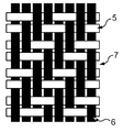
かかる2/2綾織物は、図2および図3に示されており、この場合、よこ糸は、参照符号5で示され、たて糸は、参照符号6で示され、それほど緊密ではない織成が施されて樹脂を挿通させる隙間7が自由な状態で残されている。良好な結果は、2/2綾織物で得られた。
Such a 2/2 twill weave is shown in FIGS. 2 and 3, where the weft yarn is indicated by
さらに有利には、よこ糸およびたて糸は各々、撚り合わせによって互いに結合されたPTFE繊維によって形成された単一のフィラメントにより形成され、このことは、フィラメント、およびかくしてよこ糸とたて糸がマトリックス内への織物の良好な繋留具合に寄与するでこぼこの表面を有することを意味している。 More advantageously, the weft yarns and the warp yarns are each formed by a single filament formed by PTFE fibers joined together by twisting, which means that the filaments, and thus the weft yarns and the warp yarns, of the fabric into the matrix. It is meant to have a bumpy surface that contributes to good anchorage.
良好な結果は、0.1〜0.14mmの平均直径を有する繊維によって形成されたモノフィラメントのかかる織成により得られた。 Good results have been obtained with such weaving of monofilaments formed by fibers having an average diameter of 0.1 to 0.14 mm.
これら繊維は、好ましくは、400デシテックスを超え、有利には少なくとも750デシテックスである番手を有し、極めて満足の行く試験結果が833デシテックスの繊維で得られた。 These fibers preferably have a count of more than 400 decitex, advantageously at least 750 decitex, with very satisfactory test results being obtained with a fiber of 833 decitex.
変形例では、織物は、各々が上述した実施例の場合のように連続したまたは短繊維によって形成された数本のフィラメントによって形成されているストランドによって形成され、かかる場合、フィラメントの番手は、低いのが良く、例えば、2本フィラメントのストランドに関し、350〜450デシテックスまたはそれ以下のオーダーのものである。織成は、撚り合わせの有無を問わず2つまたは3つの断片のストランドを集成することによって実施できる。 In a variant, the woven fabric is formed by strands formed by several filaments, each continuous or formed by short fibers, as in the above-mentioned embodiments, in which case the filament count is low. Good, for example, on the order of 350-450 decitex or less for a double filament strand. Weaving can be performed by assembling strands of two or three pieces with or without twisting.
さらに別の変形例によれば、フィラメントの表面は、たとえば微小ノッチの形成によって注意深くでこぼこにされている。 According to yet another variant, the surface of the filament is carefully roughened, for example by the formation of micronotches.
織物の厚さは、少なくとも0.30mmまたは更には少なくとも0.5mmであり、1ミリメートルを超える範囲にある値を想定することができ、これにより、用いられるべきストランドの断面を決定することができる。よこ糸とたて糸は、有利には同一である。これらの断面は、図2および図3で検討される実施例では、円板の断面である。図示していない変形例では、この断面は、長方形であり、たとえば、形状係数(最も大きな寸法と最も小さな寸法の比)は、好ましくは少なくとも2である。 The thickness of the fabric is at least 0.30 mm or even at least 0.5 mm, values in the range of more than 1 millimeter can be envisaged, which can determine the cross section of the strand to be used. .. The weft thread and the warp thread are advantageously the same. These cross sections are disc cross sections in the examples discussed in FIGS. 2 and 3. In a variant not shown, this cross section is rectangular, for example the shape factor (ratio of largest dimension to smallest dimension) is preferably at least 2.
熱安定性樹脂は、有利には、熱硬化性ポリイミド、シアネートエステルを主成分とする樹脂またはポリエーテルケトン(特に、ポリエーテルエーテルケトン(PEEK)またはポリエーテルケトンケトン(PEKK))から選択される。これらの樹脂は、最低ガラス転移温度が280℃を超える。熱硬化性ポリイミドの中で、ポリビスマレイミドまたはBMIを挙げることができる。 The heat-stable resin is advantageously selected from thermosetting polyimides, cyanate ester-based resins or polyetherketones, in particular polyetheretherketone (PEEK) or polyetherketoneketone (PEKK). .. These resins have a minimum glass transition temperature above 280°C. Among the thermosetting polyimides, mention may be made of polybismaleimide or BMI.
充填剤を熱安定性樹脂中に混ぜ込むことが有益であるとは考えられない。 It is unlikely that it would be beneficial to incorporate a filler into the heat stable resin.
補強層は、圧力が摩擦部品と対向した部品との間に加えられる(高温での加圧状態を含む)にもかかわらず、摩擦層を補強してその形状を保つ機能を有するので、理解されるように、この補強層は、代表的には多くとも13.10-6K-1に等しい極めて低い熱膨張率を有する材料(鋼に対応している)により形成されるのが有利であり、要件の関数としてこの補強層の幾何学的形状および構成を定めることは、当業者の通常の技術の範囲内にある。この補強層は、特に、自由でありまたは織物内で組み合わされた、炭素、ガラスまたはアラミドのストランドまたは繊維(ロービングと呼ばれる場合がある)を含むのが良い。 The reinforcing layer is understood because it has the function of reinforcing the friction layer and maintaining its shape despite the fact that pressure is applied between the friction part and the opposing part (including pressure at high temperature). As such, this reinforcing layer is advantageously formed of a material (corresponding to steel) having a very low coefficient of thermal expansion, typically equal to at most 13.10 -6 K -1 . It is within the ordinary skill of one in the art to define the geometry and configuration of this reinforcing layer as a function of requirements. This reinforcing layer may in particular comprise carbon or glass or aramid strands or fibers (sometimes called rovings) which are free or combined in the fabric.
摩擦層の織物は、有利には、ストリップとして利用でき、ストリップは、必要ならばプロフィールが得られるべき摩擦面の形態のネガであるプレフォームを用いることによって摩擦層を造形するための大きな自由度を提供する。ストリップの幅は、要件の関数として選択でき、この幅は、有利には、5mm〜2m、たとえば1cm〜10cm、好ましくは1.5cm〜3cmに選択される。 The fabric of the friction layer can advantageously be used as a strip, the strip having a great degree of freedom for shaping the friction layer by using a preform which is a negative of the form of the friction surface from which the profile is to be obtained if necessary. I will provide a. The width of the strip can be chosen as a function of the requirements, which width is advantageously chosen between 5 mm and 2 m, for example between 1 cm and 10 cm, preferably between 1.5 cm and 3 cm.
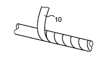
摩擦部品がベアリングである上述の場合、その製造は、かかる織物のストリップを外径が製造されるべきベアリングの内径に等しいマンドレルに巻き付けることによって開始可能であり、マンドレル上に形成された連続して位置するターンの縁と縁の接触状態を保障するようストリップを螺旋状に巻き付ける(図4参照)。理解されるように、ストリップ10の幅は、マンドレルの軸線およびかくして結果として得られるベアリングの軸線に対するよこ糸およびたて糸の傾きを決定する。事実、よこ糸およびたて糸は、それぞれ、織物のストリップに対して長手方向および横方向に配置される。
In the above case where the friction part is a bearing, its manufacture can be started by winding a strip of such a fabric around a mandrel whose outer diameter is equal to the inner diameter of the bearing to be manufactured, and which is formed continuously on the mandrel. The strip is spirally wound to ensure edge-to-edge contact of the located turns (see Figure 4). As will be appreciated, the width of the
理解されるように、摩擦中におけるよこ糸とたて糸の両方の連続性は、ベアリングの動作寿命中、良好な健全性の保持に寄与し、これらストランドに関し、ベアリングの長手方向軸線に対する40°〜60°の傾斜角がこれについて望ましいと考えられる。縁と縁を付き合わせた巻回の場合、およびさらに織物の場合(しかしながら、ストランドの場合ではなく)、65°〜89°の角度を辿る巻回を提供することが好ましい。 As will be appreciated, the continuity of both weft and warp during rubbing contributes to the retention of good integrity during the operating life of the bearing, with respect to these strands, between 40° and 60° with respect to the longitudinal axis of the bearing. It is believed that a tilt angle of is desirable for this. In the case of edge-to-edge turns, and also in the case of fabrics (but not strands), it is preferable to provide turns that follow an angle of 65° to 89°.
補強層を形成するのに、炭素もしくはガラスまたは任意他の適当な材料のストランドを任意の傾斜角度であって良い角度で巻回することも可能であろう。ストランドの巻回の場合、最適角度は、40°〜60°であると考えられるが、この角度は、用途および所望の機械的特性に応じて様々であって良い。 It would also be possible to wind strands of carbon or glass or any other suitable material at any angle of inclination to form the reinforcing layer. For strand winding, the optimum angle is considered to be 40°-60°, but this angle may vary depending on the application and the desired mechanical properties.
一方において織物のストリップ、他方において補強層のストランドは、有利には、前もって熱安定樹脂で含浸処理されるが、理解されるように、補強層が摩擦層の場合と同一の樹脂を用いて形成される場合、次の熱処理がマトリックスを互いにしっかりと取り付けるのを助けることができる。 The strips of fabric on the one hand and the strands of the reinforcing layer on the other hand are advantageously pre-impregnated with a heat-stable resin, but it will be understood that the reinforcing layer is formed using the same resin as in the case of the friction layer. If so, subsequent heat treatment can help to firmly attach the matrices to each other.
ストリップの巻回によって形成されるのではなく、変形例として、PTFE織物は、編組管状スリーブによって構成される。 Instead of being formed by winding a strip, as a variant, the PTFE fabric is constituted by a braided tubular sleeve.
容易に理解されるように、スライダ形式の摩擦部品の場合、摩擦層は、上述の織物を下に位置する補強層に取り付けるだけで形成できる。 As will be readily appreciated, in the case of slider-type friction components, the friction layer can be formed simply by attaching the fabric described above to the underlying reinforcing layer.
一例を挙げると、摩擦ベアリングを以下のようにして形成した。 As an example, the friction bearing was formed as follows.
厚さ0.3mmのPTFE織物を幅3cmのストリップの形態をした2/2綾織物の織り方と共に選択した。このストリップをガラス転移温度が285℃のポリビスマレイミド(BMI)型の熱安定性樹脂を含む110℃に維持された含浸浴中に浸漬した。 A 0.3 mm thick PTFE woven fabric was selected along with a 2/2 twill weave in the form of a 3 cm wide strip. The strip was immersed in an impregnation bath maintained at 110°C containing a polybismaleimide (BMI) type heat stable resin with a glass transition temperature of 285°C.
連続して位置するターン相互間のオーバーラップを生じさせないでマンドレルの表面全体を覆うよう注意しながらこの含浸ストリップをマンドレルに巻き付けて、マンドレルの表面全体にわたって単一の連続層を形成し、この単一連続層は、ベアリング(または複数のベアリング)を形成するようになっていた。有利には、マンドレルもまたそれ自体、含浸浴の温度に維持した。 The impregnating strip is wrapped around the mandrel, taking care to cover the entire surface of the mandrel without causing overlap between consecutively located turns to form a single continuous layer over the entire surface of the mandrel. The single continuous layer was to form the bearing (or multiple bearings). Advantageously, the mandrel itself was also maintained at the temperature of the impregnation bath.
つぎに、前もって同一の樹脂を含浸させたエポキシガラスのストランド(ロービング型のガラスフィラメントと呼ばれる)を巻回した。 Next, a strand of epoxy glass impregnated with the same resin in advance (called a roving type glass filament) was wound.
つづく重合サイクルは、170℃における4時間(これよりも長い持続時間が可能である)にわたる処理、脱型、および230℃〜250℃の温度での4時間(これよりも長い持続時間が可能である)にわたる追加の硬化処置を含んでいた。 The subsequent polymerization cycle consisted of treatment at 170° C. for 4 hours (which can be longer), demolding, and 4 hours at temperatures between 230° C. and 250° C. (which could be longer). ).
注目したこととして、次の機械加工中、PTFE繊維を切断することは難しかったが、このことは、組立体の摩耗に関して良好な性能を立証している。 Notably, it was difficult to cut the PTFE fibers during subsequent machining, which demonstrates good performance with respect to assembly wear.
以下の条件で摩擦学的試験を実施した。
‐振幅軸線の振動:100°
‐計画圧力:80MPa
‐平均速度:8mm/s
‐平均PV(圧力×速度):0.64MPa・m/s
‐当初のシャフト/ベアリング間の隙間:0.1〜0.2mm
‐ベアリングの寸法:Φint30×Φext36×Lg20
‐当初のグリース:なし
‐試験した解決手段の対向したシャフト:16NC6肌焼き
‐試験の最長持続時間:1か月(350,000サイクル)
‐周囲温度
A tribological test was conducted under the following conditions.
-Amplitude axis vibration: 100°
-Planned pressure: 80MPa
-Average speed: 8mm/s
-Average PV (pressure x velocity): 0.64 MPa·m/s
-Initial shaft/bearing clearance: 0.1-0.2mm
-Bearing dimensions: Φint30 x Φext36 x Lg20
-Initial grease: None-Countershafts of tested solutions: 16 NC6 case hardening-Maximum duration of test: 1 month (350,000 cycles)
-Ambient temperature
既知のベアリング(PTFEを入れた樹脂で被覆されたポリエステル織物で作られている、またはポリエステルのストランドおよびPTFE(最大量が50%未満のPTFE)のストランドにより形成された織物で作られている)について最高0.04またはそれどころか0.08までの摩擦係数の増大を認めたが、本発明のベアリングに関する摩擦係数は、最高350,000サイクルまでかろうじて0.02の値で実質的に一定であることを示している。 Known bearings (made of polyester woven fabric coated with resin containing PTFE, or made of polyester strands and PTFE (maximum amount less than 50% PTFE) strands) Of up to 0.04 or even 0.08, the coefficient of friction for the bearings of the invention is substantially constant at a value of barely 0.02 up to 350,000 cycles. Is shown.
対向した部品のシャフトの中心のところでの温度の変化をモニタしたとき、この温度は、公知のベアリングについてほぼ50℃またはそれどころか60℃まで増大し、温度は、本発明のベアリングについては40℃未満に維持されたことが注目され、このことは、本発明のベアリングについて散逸するエネルギーが公知のベアリングの場合よりも少ないことを明らかに反映している。 When monitoring the change in temperature at the center of the shaft of the opposing part, this temperature increases to approximately 50°C or even 60°C for known bearings, and the temperature is less than 40°C for the bearings of the present invention. It was noted that it was maintained, which clearly reflects less energy dissipated for the bearing of the present invention than for known bearings.
たとえそうであっても、本発明のベアリングの全体的摩耗は、公知のベアリングの全体的摩耗よりも大きく、対向した部品の示す摩耗は、極めて僅かであることが注目されるが、この摩耗は、見掛け上のものであるに過ぎず、事実、加えられた接触圧力を受けた摩擦層の粉砕現象の存在を反映している。 Even so, it is noted that the overall wear of the bearings of the present invention is greater than that of known bearings, and that the opposing parts show very little wear. , Only apparent, and in fact reflects the presence of the crushing phenomenon of the friction layer under the applied contact pressure.
さらに、本発明のベアリングを以下の条件下で試験した。
‐振幅軸線の振動:100°
‐計画圧力:80MPa
‐平均速度:8mm/s
‐平均PV(圧力×速度):0.64MPa・m/s
‐当初のシャフト/ベアリング間の隙間:0.1〜0.2mm
‐ベアリングの寸法:Φint30×Φext36×Lg20
‐当初のグリース:なし
‐試験した解決手段の対向したシャフト:16NC6肌焼き
‐試験の最長持続時間:1か月(350,000サイクル)
‐50℃から280℃まで変化する温度(周囲)‐これら温度レベルの間、温度を一定に維持することが困難であった。
Further, the bearing of the present invention was tested under the following conditions.
-Amplitude axis vibration: 100°
-Planned pressure: 80MPa
-Average speed: 8mm/s
-Average PV (pressure x velocity): 0.64 MPa·m/s
-Initial shaft/bearing clearance: 0.1-0.2mm
-Bearing dimensions: Φint30 x Φext36 x Lg20
-Initial grease: None-Countershafts of tested solutions: 16 NC6 case hardening-Maximum duration of test: 1 month (350,000 cycles)
Temperature varying from -50°C to 280°C (ambient)-It was difficult to keep the temperature constant during these temperature levels.
摩擦係数は、280℃までの増大にもかかわらず、実質的に一定であることを示している。 The coefficient of friction is shown to be substantially constant despite the increase up to 280°C.
これらの試験結果の示すところによれば、本発明のベアリングは、極めて低い温度係数と、最高250℃を超え、250℃から280℃までの範囲の温度での良好な性能とを満足の行く程度に兼ね備えている。 These test results show that the bearings of the present invention satisfactorily have an extremely low temperature coefficient and good performance at temperatures above 250°C up to 250°C to 280°C. It has both.
Claims (12)
Priority Applications (1)
| Application Number | Priority Date | Filing Date | Title |
|---|---|---|---|
| JP2023001488A JP2023057079A (en) | 2014-07-16 | 2023-01-10 | Self-lubricating composite friction part |
Applications Claiming Priority (2)
| Application Number | Priority Date | Filing Date | Title |
|---|---|---|---|
| FR1456836A FR3023880B1 (en) | 2014-07-16 | 2014-07-16 | AUTOLUBRICATING FRICTION COMPOSITE PIECE |
| FR1456836 | 2014-07-16 |
Related Parent Applications (1)
| Application Number | Title | Priority Date | Filing Date |
|---|---|---|---|
| JP2017502265A Division JP2017523360A (en) | 2014-07-16 | 2015-06-29 | Self-slip composite friction parts |
Related Child Applications (1)
| Application Number | Title | Priority Date | Filing Date |
|---|---|---|---|
| JP2023001488A Division JP2023057079A (en) | 2014-07-16 | 2023-01-10 | Self-lubricating composite friction part |
Publications (1)
| Publication Number | Publication Date |
|---|---|
| JP2020122575A true JP2020122575A (en) | 2020-08-13 |
Family
ID=51519088
Family Applications (3)
| Application Number | Title | Priority Date | Filing Date |
|---|---|---|---|
| JP2017502265A Pending JP2017523360A (en) | 2014-07-16 | 2015-06-29 | Self-slip composite friction parts |
| JP2020070188A Pending JP2020122575A (en) | 2014-07-16 | 2020-04-09 | Self-lubricating composite friction part |
| JP2023001488A Pending JP2023057079A (en) | 2014-07-16 | 2023-01-10 | Self-lubricating composite friction part |
Family Applications Before (1)
| Application Number | Title | Priority Date | Filing Date |
|---|---|---|---|
| JP2017502265A Pending JP2017523360A (en) | 2014-07-16 | 2015-06-29 | Self-slip composite friction parts |
Family Applications After (1)
| Application Number | Title | Priority Date | Filing Date |
|---|---|---|---|
| JP2023001488A Pending JP2023057079A (en) | 2014-07-16 | 2023-01-10 | Self-lubricating composite friction part |
Country Status (18)
| Country | Link |
|---|---|
| US (2) | US10900522B2 (en) |
| EP (1) | EP3169907B1 (en) |
| JP (3) | JP2017523360A (en) |
| KR (1) | KR102041692B1 (en) |
| CN (1) | CN106662142B (en) |
| AU (1) | AU2015288999B2 (en) |
| BR (1) | BR112017000265B1 (en) |
| CA (1) | CA2954579C (en) |
| DK (1) | DK3169907T3 (en) |
| ES (1) | ES2906616T3 (en) |
| FR (1) | FR3023880B1 (en) |
| HU (1) | HUE057953T2 (en) |
| MX (1) | MX2017000703A (en) |
| PL (1) | PL3169907T3 (en) |
| PT (1) | PT3169907T (en) |
| RU (1) | RU2675156C2 (en) |
| TW (1) | TWI698593B (en) |
| WO (1) | WO2016009124A1 (en) |
Families Citing this family (8)
| Publication number | Priority date | Publication date | Assignee | Title |
|---|---|---|---|---|
| FR2997146B1 (en) * | 2012-10-22 | 2014-11-21 | Hydromecanique & Frottement | SELF-LUBRICATING JOINT ELEMENT OPERATING IN HIGH DYNAMIC LOADS |
| FR3023880B1 (en) * | 2014-07-16 | 2017-05-26 | Hydromecanique & Frottement | AUTOLUBRICATING FRICTION COMPOSITE PIECE |
| DE102014220375A1 (en) * | 2014-10-08 | 2016-04-28 | Aktiebolaget Skf | bearing bracket |
| US11644064B2 (en) * | 2017-02-24 | 2023-05-09 | Vibracoustic Se | Bearing bush |
| US11221043B2 (en) * | 2019-07-29 | 2022-01-11 | Ovivo Inc. | Stabilizer bearing for mast of rotary distributor |
| CN111014531B (en) * | 2019-12-04 | 2021-08-27 | 上海交通大学 | Cold forging lubricating method based on net-shaped storage structure |
| MX2022007319A (en) * | 2019-12-20 | 2022-07-13 | Toray Industries | Fabric, and cable cover for robot arm. |
| CN111844968A (en) * | 2020-07-09 | 2020-10-30 | 中国科学院兰州化学物理研究所 | Preparation method of polyimide fiber/polytetrafluoroethylene fiber self-lubricating fabric liner material |
Citations (6)
| Publication number | Priority date | Publication date | Assignee | Title |
|---|---|---|---|---|
| JPS5368341A (en) * | 1976-11-30 | 1978-06-17 | Oiles Industry Co Ltd | Method of producing sliding part of fluorine resin union cloth |
| JPS61228122A (en) * | 1985-03-29 | 1986-10-11 | Nok Corp | Sliding material |
| JPH11293268A (en) * | 1998-04-08 | 1999-10-26 | Toray Ind Inc | Sliding member |
| JP2001146815A (en) * | 1999-11-24 | 2001-05-29 | Du Pont Toray Co Ltd | Fiber sheet for reinforcement |
| JP2009120984A (en) * | 2007-11-14 | 2009-06-04 | Toray Ind Inc | Fluoro-fiber spun yarn and method for producing the same |
| JP2010120992A (en) * | 2008-11-17 | 2010-06-03 | Oiles Ind Co Ltd | Fiber-reinforced resin composition for sliding member, and laminated sliding member |
Family Cites Families (26)
| Publication number | Priority date | Publication date | Assignee | Title |
|---|---|---|---|---|
| US2804886A (en) | 1955-11-04 | 1957-09-03 | Charles S White | Low friction fabric material |
| US3458374A (en) * | 1965-12-15 | 1969-07-29 | Samuel M Shobert | Method of making a braided tubular bearing having a polytetrafluoroethylene liner |
| GB1156165A (en) * | 1966-09-06 | 1969-06-25 | American Metal Prod | A Bearing Element and method for making same |
| FR2168662A5 (en) * | 1972-01-19 | 1973-08-31 | Skf Cie Applic Mecanique | |
| US3804479A (en) | 1972-12-21 | 1974-04-16 | Rexnord Inc | Low friction fabric-lined bearings and improved fabric therefor |
| GB1439030A (en) | 1973-08-03 | 1976-06-09 | Shobert S M | Plastics bearing |
| US4006051A (en) * | 1974-02-21 | 1977-02-01 | New Hampshire Ball Bearings, Inc. | Method of preparing a low-friction laminate liner for bearings |
| US4111499A (en) * | 1975-03-31 | 1978-09-05 | The Heim Universal Corporation | Bearing assembly and liner |
| GB2095170A (en) * | 1981-03-16 | 1982-09-29 | Gen Electric | Fibrous bearing material |
| US4358167A (en) * | 1981-05-26 | 1982-11-09 | The Torrington Company | Bearing element |
| GB2170279B (en) | 1985-01-30 | 1988-10-19 | Ampep Plc | Self-lubricating bearings |
| JPH07113373B2 (en) * | 1986-01-20 | 1995-12-06 | キヤノン株式会社 | Slide rail |
| JPH0721318B2 (en) | 1990-05-16 | 1995-03-08 | 日本ピラー工業株式会社 | Polymer composite material |
| JP3544788B2 (en) * | 1995-06-28 | 2004-07-21 | 三井化学株式会社 | Linear polyamic acid, linear polyimide and thermosetting polyimide |
| US5952067A (en) * | 1996-12-02 | 1999-09-14 | A&P Technology, Inc. | Braided structure having uncrimped strands |
| US6264369B1 (en) * | 1999-01-29 | 2001-07-24 | General Electric Company | Variable vane seal and washer materials |
| DE19915348B4 (en) * | 1999-04-06 | 2019-06-27 | Schaeffler Technologies AG & Co. KG | bearings |
| RU2215206C1 (en) * | 2002-06-24 | 2003-10-27 | Общество с ограниченной ответственностью "Борец" | Friction couple and impeller of immersed multiple-impeller centrifugal pump provided with friction couple |
| JP2005220486A (en) * | 2004-02-06 | 2005-08-18 | Toray Ind Inc | Fluorofiber union cloth and composite material |
| TWI401160B (en) * | 2004-09-24 | 2013-07-11 | Itochu Corp | Composite material, and product and fiber-metal composite material comprising the same |
| US8021051B2 (en) * | 2006-07-07 | 2011-09-20 | Federal-Mogul World Wide, Inc. | Sleeve bearing assembly and method of construction |
| US8152380B2 (en) * | 2006-07-07 | 2012-04-10 | Federal-Mogul World Wide, Inc. | Sleeve bearing assembly and method of construction |
| JP5368341B2 (en) | 2010-02-25 | 2013-12-18 | 株式会社ニューギン | Game machine |
| JP2011190561A (en) * | 2010-03-16 | 2011-09-29 | Nihon Gore Kk | Method for producing fabric, and fabric |
| FR2997146B1 (en) | 2012-10-22 | 2014-11-21 | Hydromecanique & Frottement | SELF-LUBRICATING JOINT ELEMENT OPERATING IN HIGH DYNAMIC LOADS |
| FR3023880B1 (en) * | 2014-07-16 | 2017-05-26 | Hydromecanique & Frottement | AUTOLUBRICATING FRICTION COMPOSITE PIECE |
-
2014
- 2014-07-16 FR FR1456836A patent/FR3023880B1/en active Active
-
2015
- 2015-06-29 KR KR1020177003919A patent/KR102041692B1/en active IP Right Grant
- 2015-06-29 ES ES15742354T patent/ES2906616T3/en active Active
- 2015-06-29 HU HUE15742354A patent/HUE057953T2/en unknown
- 2015-06-29 AU AU2015288999A patent/AU2015288999B2/en active Active
- 2015-06-29 JP JP2017502265A patent/JP2017523360A/en active Pending
- 2015-06-29 DK DK15742354.2T patent/DK3169907T3/en active
- 2015-06-29 PL PL15742354T patent/PL3169907T3/en unknown
- 2015-06-29 US US15/325,447 patent/US10900522B2/en active Active
- 2015-06-29 RU RU2017104855A patent/RU2675156C2/en active
- 2015-06-29 CA CA2954579A patent/CA2954579C/en active Active
- 2015-06-29 PT PT157423542T patent/PT3169907T/en unknown
- 2015-06-29 EP EP15742354.2A patent/EP3169907B1/en active Active
- 2015-06-29 MX MX2017000703A patent/MX2017000703A/en unknown
- 2015-06-29 WO PCT/FR2015/051765 patent/WO2016009124A1/en active Application Filing
- 2015-06-29 CN CN201580038528.0A patent/CN106662142B/en active Active
- 2015-06-29 BR BR112017000265-5A patent/BR112017000265B1/en active IP Right Grant
- 2015-07-15 TW TW104122920A patent/TWI698593B/en active
-
2020
- 2020-04-09 JP JP2020070188A patent/JP2020122575A/en active Pending
- 2020-12-31 US US17/247,945 patent/US11781594B2/en active Active
-
2023
- 2023-01-10 JP JP2023001488A patent/JP2023057079A/en active Pending
Patent Citations (6)
| Publication number | Priority date | Publication date | Assignee | Title |
|---|---|---|---|---|
| JPS5368341A (en) * | 1976-11-30 | 1978-06-17 | Oiles Industry Co Ltd | Method of producing sliding part of fluorine resin union cloth |
| JPS61228122A (en) * | 1985-03-29 | 1986-10-11 | Nok Corp | Sliding material |
| JPH11293268A (en) * | 1998-04-08 | 1999-10-26 | Toray Ind Inc | Sliding member |
| JP2001146815A (en) * | 1999-11-24 | 2001-05-29 | Du Pont Toray Co Ltd | Fiber sheet for reinforcement |
| JP2009120984A (en) * | 2007-11-14 | 2009-06-04 | Toray Ind Inc | Fluoro-fiber spun yarn and method for producing the same |
| JP2010120992A (en) * | 2008-11-17 | 2010-06-03 | Oiles Ind Co Ltd | Fiber-reinforced resin composition for sliding member, and laminated sliding member |
Also Published As
| Publication number | Publication date |
|---|---|
| US20210123478A1 (en) | 2021-04-29 |
| BR112017000265A2 (en) | 2017-10-31 |
| AU2015288999B2 (en) | 2018-11-08 |
| US11781594B2 (en) | 2023-10-10 |
| EP3169907B1 (en) | 2021-12-22 |
| US20170175812A1 (en) | 2017-06-22 |
| CA2954579A1 (en) | 2016-01-21 |
| WO2016009124A1 (en) | 2016-01-21 |
| TW201612431A (en) | 2016-04-01 |
| HUE057953T2 (en) | 2022-06-28 |
| US10900522B2 (en) | 2021-01-26 |
| PL3169907T3 (en) | 2022-07-11 |
| KR20170034898A (en) | 2017-03-29 |
| DK3169907T3 (en) | 2022-03-07 |
| CA2954579C (en) | 2019-05-14 |
| JP2017523360A (en) | 2017-08-17 |
| MX2017000703A (en) | 2017-11-30 |
| FR3023880B1 (en) | 2017-05-26 |
| CN106662142A (en) | 2017-05-10 |
| RU2675156C2 (en) | 2018-12-17 |
| PT3169907T (en) | 2022-03-03 |
| ES2906616T3 (en) | 2022-04-19 |
| KR102041692B1 (en) | 2019-11-06 |
| AU2015288999A1 (en) | 2017-03-09 |
| EP3169907A1 (en) | 2017-05-24 |
| BR112017000265B1 (en) | 2021-08-10 |
| RU2017104855A3 (en) | 2018-08-16 |
| FR3023880A1 (en) | 2016-01-22 |
| RU2017104855A (en) | 2018-08-16 |
| CN106662142B (en) | 2019-10-25 |
| TWI698593B (en) | 2020-07-11 |
| JP2023057079A (en) | 2023-04-20 |
Similar Documents
| Publication | Publication Date | Title |
|---|---|---|
| JP2020122575A (en) | Self-lubricating composite friction part | |
| JP2023057079A5 (en) | ||
| JP2005220486A (en) | Fluorofiber union cloth and composite material | |
| FR3022320A1 (en) | TUBULAR DRIVE WITH COMPOSITE RETAINING STRIP | |
| EP2955400B1 (en) | Bearing liner | |
| JP4790610B2 (en) | Synchronizer ring | |
| CA2894488A1 (en) | Reinforced structural component made of composite material | |
| FR2913092A1 (en) | FLEXIBLE SOFT PIPE | |
| JPH11269280A (en) | Pluororesin ring-shaped sliding part | |
| EP3101290A1 (en) | Curved sliding liner and curved sliding member | |
| US4040883A (en) | Method of making a low-friction fabric bearing | |
| CN111139653A (en) | Self-lubricating fabric and application thereof | |
| KR20050081493A (en) | A self-lubricating bearing | |
| CN102912523A (en) | Carbon fiber cloth and application thereof to friction-resistant component | |
| AU2013336453B2 (en) | Self-lubricating articulation element made from a composite material and operating under high dynamic loadings | |
| JP6610042B2 (en) | Sliding member and brake member for wind turbine yaw control | |
| RU2569839C1 (en) | Multi-component complex reinforcing thread | |
| JP2006153268A (en) | High load transmission belt | |
| CN116997693A (en) | Woven fabric and sliding material | |
| JP2004044642A (en) | Compound belt | |
| JP6144553B2 (en) | Sealing sliding member | |
| JP2018155290A (en) | Slide bearing |
Legal Events
| Date | Code | Title | Description |
|---|---|---|---|
| A521 | Request for written amendment filed |
Free format text: JAPANESE INTERMEDIATE CODE: A523 Effective date: 20200511 |
|
| A621 | Written request for application examination |
Free format text: JAPANESE INTERMEDIATE CODE: A621 Effective date: 20200511 |
|
| A977 | Report on retrieval |
Free format text: JAPANESE INTERMEDIATE CODE: A971007 Effective date: 20210218 |
|
| A131 | Notification of reasons for refusal |
Free format text: JAPANESE INTERMEDIATE CODE: A131 Effective date: 20210308 |
|
| A521 | Request for written amendment filed |
Free format text: JAPANESE INTERMEDIATE CODE: A523 Effective date: 20210608 |
|
| A131 | Notification of reasons for refusal |
Free format text: JAPANESE INTERMEDIATE CODE: A131 Effective date: 20211108 |
|
| A601 | Written request for extension of time |
Free format text: JAPANESE INTERMEDIATE CODE: A601 Effective date: 20220207 |
|
| A601 | Written request for extension of time |
Free format text: JAPANESE INTERMEDIATE CODE: A601 Effective date: 20220408 |
|
| A521 | Request for written amendment filed |
Free format text: JAPANESE INTERMEDIATE CODE: A523 Effective date: 20220506 |
|
| A02 | Decision of refusal |
Free format text: JAPANESE INTERMEDIATE CODE: A02 Effective date: 20220907 |