RU2675155C2 - Non-synchronous gear meshing in limited-slip differentials - Google Patents
Non-synchronous gear meshing in limited-slip differentials Download PDFInfo
- Publication number
- RU2675155C2 RU2675155C2 RU2016140939A RU2016140939A RU2675155C2 RU 2675155 C2 RU2675155 C2 RU 2675155C2 RU 2016140939 A RU2016140939 A RU 2016140939A RU 2016140939 A RU2016140939 A RU 2016140939A RU 2675155 C2 RU2675155 C2 RU 2675155C2
- Authority
- RU
- Russia
- Prior art keywords
- gear
- semi
- axial
- gears
- pinion
- Prior art date
Links
- 238000000034 method Methods 0.000 claims description 24
- 230000008569 process Effects 0.000 claims description 24
- 230000003993 interaction Effects 0.000 claims description 20
- 230000007246 mechanism Effects 0.000 abstract description 8
- 239000000126 substance Substances 0.000 abstract 1
- 230000008878 coupling Effects 0.000 description 8
- 238000010168 coupling process Methods 0.000 description 8
- 238000005859 coupling reaction Methods 0.000 description 8
- 230000005540 biological transmission Effects 0.000 description 6
- 230000008859 change Effects 0.000 description 3
- 239000012530 fluid Substances 0.000 description 2
- 230000000712 assembly Effects 0.000 description 1
- 238000000429 assembly Methods 0.000 description 1
- 230000004069 differentiation Effects 0.000 description 1
- 230000004048 modification Effects 0.000 description 1
- 238000012986 modification Methods 0.000 description 1
Images
Classifications
-
- F—MECHANICAL ENGINEERING; LIGHTING; HEATING; WEAPONS; BLASTING
- F16—ENGINEERING ELEMENTS AND UNITS; GENERAL MEASURES FOR PRODUCING AND MAINTAINING EFFECTIVE FUNCTIONING OF MACHINES OR INSTALLATIONS; THERMAL INSULATION IN GENERAL
- F16H—GEARING
- F16H48/00—Differential gearings
- F16H48/06—Differential gearings with gears having orbital motion
- F16H48/08—Differential gearings with gears having orbital motion comprising bevel gears
-
- F—MECHANICAL ENGINEERING; LIGHTING; HEATING; WEAPONS; BLASTING
- F16—ENGINEERING ELEMENTS AND UNITS; GENERAL MEASURES FOR PRODUCING AND MAINTAINING EFFECTIVE FUNCTIONING OF MACHINES OR INSTALLATIONS; THERMAL INSULATION IN GENERAL
- F16H—GEARING
- F16H48/00—Differential gearings
- F16H48/36—Differential gearings characterised by intentionally generating speed difference between outputs
-
- F—MECHANICAL ENGINEERING; LIGHTING; HEATING; WEAPONS; BLASTING
- F16—ENGINEERING ELEMENTS AND UNITS; GENERAL MEASURES FOR PRODUCING AND MAINTAINING EFFECTIVE FUNCTIONING OF MACHINES OR INSTALLATIONS; THERMAL INSULATION IN GENERAL
- F16H—GEARING
- F16H48/00—Differential gearings
- F16H48/38—Constructional details
- F16H48/40—Constructional details characterised by features of the rotating cases
-
- F—MECHANICAL ENGINEERING; LIGHTING; HEATING; WEAPONS; BLASTING
- F16—ENGINEERING ELEMENTS AND UNITS; GENERAL MEASURES FOR PRODUCING AND MAINTAINING EFFECTIVE FUNCTIONING OF MACHINES OR INSTALLATIONS; THERMAL INSULATION IN GENERAL
- F16H—GEARING
- F16H48/00—Differential gearings
- F16H48/06—Differential gearings with gears having orbital motion
- F16H48/08—Differential gearings with gears having orbital motion comprising bevel gears
- F16H2048/082—Differential gearings with gears having orbital motion comprising bevel gears characterised by the arrangement of output shafts
-
- F—MECHANICAL ENGINEERING; LIGHTING; HEATING; WEAPONS; BLASTING
- F16—ENGINEERING ELEMENTS AND UNITS; GENERAL MEASURES FOR PRODUCING AND MAINTAINING EFFECTIVE FUNCTIONING OF MACHINES OR INSTALLATIONS; THERMAL INSULATION IN GENERAL
- F16H—GEARING
- F16H48/00—Differential gearings
- F16H48/06—Differential gearings with gears having orbital motion
- F16H48/08—Differential gearings with gears having orbital motion comprising bevel gears
- F16H2048/087—Differential gearings with gears having orbital motion comprising bevel gears characterised by the pinion gears, e.g. their type or arrangement
Landscapes
- Engineering & Computer Science (AREA)
- General Engineering & Computer Science (AREA)
- Mechanical Engineering (AREA)
- Retarders (AREA)
Abstract
Description
Область техникиTechnical field
Изобретение относится в целом к узлам дифференциальных передач, в частности, к узлу дифференциальной передачи с полуосевыми шестернями, входящими в зацепление со сдвигом по времени.The invention relates generally to nodes of differential gears, in particular, to a differential gear node with semi-axial gears engaged with a time shift.
Предшествующий уровень техникиState of the art
В узле моста может быть использован дифференциальный механизм для передачи крутящего момента от карданного вала на пару выходных валов. Привод дифференциала от карданного вала может осуществляться с помощью конической шестерни, находящейся в зацеплении с кольцевой шестерней, установленной на корпусе дифференциала. В автомобильных средствах передвижения дифференциал позволяет шинам, установленным с обеих сторон моста, вращаться с различными скоростями. Это очень важно, поскольку при повороте автомобиля внешняя шина проходит по более длинной дуге, чем внутренняя шина. Таким образом, внешняя шина должна вращаться с более высокой скоростью, чем внутренняя шина, чтобы компенсировать разницу по длине дуги. Дифференциал содержит корпус и зубчатую передачу, обеспечивающую возможность передачи крутящего момента с карданного вала на выходные валы, позволяя в то же время выходным валам вращаться с разными скоростями, если это необходимо. Зубчатая передача в общем случае может включать в себя пару полуосевых шестерен, установленных с возможностью вращения совместно с соответствующими выходными валами. Ряд крестовин или валы-шестерни неподвижно прикреплены к корпусу дифференциала для вращения совместно с ним. Соответствующее количество ведущих шестерен установлены с возможностью вращения вместе с валами-шестернями дифференциала и находятся в зацеплении с обеими полуосевыми шестернями.A differential mechanism can be used in the bridge assembly to transmit torque from the driveshaft to a pair of output shafts. The differential drive from the propeller shaft can be carried out using a bevel gear meshing with the ring gear mounted on the differential housing. In automotive vehicles, the differential allows tires mounted on both sides of the axle to rotate at different speeds. This is very important, because when turning the car, the outer tire runs along a longer arc than the inner tire. Thus, the outer tire must rotate at a higher speed than the inner tire in order to compensate for the difference in arc length. The differential comprises a housing and a gear transmission, which provides the possibility of transmitting torque from the driveshaft to the output shafts, while allowing the output shafts to rotate at different speeds, if necessary. The gear transmission in the General case may include a pair of semi-axial gears mounted for rotation together with the corresponding output shafts. A number of crosses or pinion shafts are fixedly attached to the differential housing for rotation together with it. An appropriate number of drive gears are rotatably mounted with the differential gear shafts and engaged with both semi-axial gears.
Некоторые механизмы дифференциальной передачи включают в себя механизмы, изменяющие силу сцепления. Как правило, между одной из полуосевых шестерен и прилегающей поверхностью корпуса может быть установлен пакет муфты. При работе пакет муфты или блокирующее устройство ограничивают вращение корпуса и одной из полуосевых шестерен относительно друг друга. В таких дифференциалах, введение в зацепление пакета муфты или блокирующего устройства (замедляющего дифференциацию) может осуществляться несколькими различными способами. Некоторые конфигурации включают в себя поршень, который обеспечивает перемещение пакета муфты между разблокированным, блокированным и частично блокированным положениями. В некоторых конструкциях приведение поршня в действие осуществляется с помощью гидрожидкости.Some differential transmission mechanisms include mechanisms that change traction. As a rule, a coupling package can be installed between one of the semi-axial gears and the adjacent surface of the housing. During operation, the clutch package or locking device limits the rotation of the housing and one of the semi-axial gears relative to each other. In such differentials, the engagement of a clutch package or a locking device (delaying differentiation) can be carried out in several different ways. Some configurations include a piston that allows the clutch pack to move between unlocked, locked, and partially locked positions. In some designs, the piston is actuated using a fluid.
Описание уровня техники предназначено для того, чтобы раскрыть в целом сущность изобретения.The description of the prior art is intended to disclose in general the essence of the invention.
Раскрытие изобретенияDisclosure of invention
Дифференциальный механизм, выполненный в соответствии с одним из возможных вариантов осуществления изобретения, может содержать корпус дифференциала, первую полуосевую шестерню, вторую полуосевую шестерню, первую ведущую шестерню и вторую ведущую шестерню. Корпус дифференциала может содержать первое и второе отверстия для выходных валов, соосные с осью вращения корпуса дифференциала. Первая полуосевая шестерня может быть установлена с возможностью вращения внутри корпуса дифференциала и может иметь первый внешний диаметр. Вторая полуосевая шестерня может быть установлена с возможностью вращения внутри корпуса дифференциала и может иметь второй внешний диаметр. Первая ведущая шестерня может находиться в зацеплении для вращения совместно с первой полуосевой шестерней в процессе первого зацепления. Вторая ведущая шестерня может находиться в зацеплении для вращения совместно со второй полуосевой шестерней в процессе второго зацепления. Первая и вторая ведущие шестерни образуют устройство для передачи крутящего момента между первой и второй ведущими шестернями и первой и второй полуосевыми шестернями для вращения первой и второй полуосевых шестерен относительно оси вращения. Первый и второй внешние диаметры отличаются таким образом, что процессы первого и второго зацепления смещены по времени относительно друг друга.The differential mechanism, made in accordance with one of the possible embodiments of the invention, may include a differential case, a first semi-axial gear, a second semi-axial gear, a first pinion gear and a second pinion gear. The differential housing may contain first and second openings for the output shafts, coaxial with the axis of rotation of the differential housing. The first semi-axial gear may be rotatably mounted inside the differential housing and may have a first outer diameter. The second semi-axial gear may be rotatably mounted inside the differential housing and may have a second outer diameter. The first drive gear may be engaged to rotate together with the first semi-axial gear during the first engagement. The second drive gear may be engaged to rotate together with the second semi-axial gear during the second engagement. The first and second drive gears form a device for transmitting torque between the first and second drive gears and the first and second half-axis gears for rotating the first and second half-axis gears relative to the axis of rotation. The first and second outer diameters differ in such a way that the processes of the first and second engagement are time shifted relative to each other.
Согласно дополнительным особенностям изобретения процессы первого и второго зацепления происходят в различных угловых положениях. Процессы первого и второго зацепления могут не совпадать по фазе. Первая полуосевая шестерня и первая ведущая шестерня могут иметь первый коэффициент перекрытия. Вторая полуосевая шестерня и вторая ведущая шестерня могут иметь второй коэффициент перекрытия. Первый и второй коэффициенты перекрытия могут отличаться друг от друга. Первая полуосевая шестерня и первая ведущая шестерня могут иметь первую длину активной линии зацепления. Вторая полуосевая шестерня и вторая ведущая шестерня могут иметь вторую длину активной линии зацепления. Первая длина активной линии зацепления может отличаться от второй длины активной линии зацепления.According to additional features of the invention, the processes of the first and second engagement occur in different angular positions. The processes of the first and second gears may not coincide in phase. The first semi-axial gear and the first drive gear may have a first overlap coefficient. The second semi-axial gear and the second drive gear may have a second overlap coefficient. The first and second overlap coefficients may differ from each other. The first semi-axial gear and the first drive gear may have a first length of an active engagement line. The second semi-axial gear and the second drive gear may have a second length of the active engagement line. The first length of the active line of engagement may differ from the second length of the active line of engagement.
Согласно другим особенностям первая ведущая шестерня может иметь первый ряд зубьев первой ведущей шестерни, каждый из которых имеет вершину. Серия первых контактов соответствующих вершин зубьев первой ведущей шестерни с соответствующими зубьями первой полуосевой шестерни может происходить в первую последовательность моментов времени контакта. Вторая ведущая шестерня может иметь второй ряд зубьев второй ведущей шестерни, каждый из которых имеет свою вершину. Серия вторых контактов соответствующих вершин зубьев второй ведущей шестерни с соответствующими зубьями второй полуосевой шестерни может происходить во вторую последовательность моментов времени контакта. Каждый момент времени первой последовательности моментов времени контакта смещен относительно каждого из моментов времени второй последовательности моментов времени контакта. Первая полуосевая шестерня и первая ведущая шестерня могут иметь первую линию взаимодействия. Вторая полуосевая шестерня и вторая ведущая шестерня могут иметь вторую линию взаимодействия. Первая линия взаимодействия может отличаться от второй линии взаимодействия.According to other features, the first drive gear may have a first row of teeth of the first drive gear, each of which has an apex. A series of first contacts of the corresponding vertices of the teeth of the first pinion gear with the corresponding teeth of the first semi-axial gear can occur in the first sequence of moments of contact time. The second pinion gear may have a second row of teeth of the second pinion gear, each of which has its own apex. A series of second contacts of the corresponding vertices of the teeth of the second pinion gear with the corresponding teeth of the second semi-axial gear can occur in the second sequence of contact times. Each point in time of the first sequence of points in time of contact is offset relative to each of the points in time of the second sequence of points of time of contact. The first semi-axial gear and the first drive gear may have a first line of interaction. The second semi-axial gear and the second drive gear may have a second line of interaction. The first line of interaction may differ from the second line of interaction.
Дифференциальный механизм, выполненный в соответствии с другим возможным вариантом осуществления изобретения, может содержать корпус дифференциала, первую полуосевую шестерню, вторую полуосевую шестерню, первую ведущую шестерню и вторую ведущую шестерню. Корпус дифференциала может содержать первое и второе отверстия для выходных валов, соосные с осями вращения корпуса дифференциала. Первая полуосевая шестерня может быть установлена с возможностью вращения внутри корпуса дифференциала и может иметь первый внешний диаметр. Вторая полуосевая шестерня может быть установлена с возможностью вращения внутри корпуса дифференциала и может иметь второй внешний диаметр. Первая ведущая шестерня может находиться в зацеплении для вращения совместно с первой полуосевой шестерней в процессе первого зацепления. Вторая ведущая шестерня может находиться в зацеплении для вращения совместно со второй полуосевой шестерней в процессе второго зацепления. Первая и вторая ведущие шестерни образуют устройство для передачи крутящего момента между первой и второй ведущими шестернями и первой и второй полуосевыми шестернями для вращения первой и второй полуосевых шестерен вокруг оси вращения. Первая полуосевая шестерня и первая ведущая шестерня могут иметь первый коэффициент перекрытия. Вторая полуосевая шестерня и вторая ведущая шестерня могут иметь второй коэффициент перекрытия. Первый и второй коэффициенты перекрытия могут отличаться друг от друга.A differential mechanism made in accordance with another possible embodiment of the invention may comprise a differential case, a first semi-axial gear, a second semi-axial gear, a first pinion gear and a second pinion gear. The differential housing may contain first and second openings for the output shafts, coaxial with the axes of rotation of the differential housing. The first semi-axial gear may be rotatably mounted inside the differential housing and may have a first outer diameter. The second semi-axial gear may be rotatably mounted inside the differential housing and may have a second outer diameter. The first drive gear may be engaged to rotate together with the first semi-axial gear during the first engagement. The second drive gear may be engaged to rotate together with the second semi-axial gear during the second engagement. The first and second drive gears form a device for transmitting torque between the first and second drive gears and the first and second half-axis gears for rotating the first and second half-axis gears around the axis of rotation. The first semi-axial gear and the first drive gear may have a first overlap coefficient. The second semi-axial gear and the second drive gear may have a second overlap coefficient. The first and second overlap coefficients may differ from each other.
Согласно другим особенностям процессы первого и второго зацепления могут не совпадать по фазе. Первая полуосевая шестерня и первая ведущая шестерня могут иметь первую длину активной линии зацепления. Вторая полуосевая шестерня и вторая ведущая шестерня могут иметь вторую длину активной линии зацепления. Первая длина активной линии зацепления может отличаться от второй длины активной линии зацепления. Первый и второй внешние диаметры отличаются друг от друга таким образом, что процессы первого и второго зацепления смещены по времени относительно друг друга. Первая полуосевая шестерня и первая ведущая шестерня могут иметь первую линию взаимодействия. Вторая полуосевая шестерня и вторая ведущая шестерня могут иметь вторую линию взаимодействия. Первая линия взаимодействия может отличаться от второй линии взаимодействия.According to other features, the processes of the first and second gears may not coincide in phase. The first semi-axial gear and the first drive gear may have a first length of an active engagement line. The second semi-axial gear and the second drive gear may have a second length of the active engagement line. The first length of the active line of engagement may differ from the second length of the active line of engagement. The first and second outer diameters differ from each other in such a way that the processes of the first and second engagement are offset in time relative to each other. The first semi-axial gear and the first drive gear may have a first line of interaction. The second semi-axial gear and the second drive gear may have a second line of interaction. The first line of interaction may differ from the second line of interaction.
Согласно другим вариантам осуществления дифференциальный механизм может содержать корпус дифференциала, первую полуосевую шестерню, вторую полуосевую шестерню, первую ведущую шестерню и вторую ведущую шестерню. Корпус дифференциала может содержать первое и второе отверстия для выходных валов, соосные с осями вращения корпуса дифференциала. Первая полуосевая шестерня может быть установлена с возможностью вращения внутри корпуса дифференциала и может иметь первый внешний диаметр. Вторая полуосевая шестерня может быть установлена с возможностью вращения внутри корпуса дифференциала и может иметь второй внешний диаметр. Первая ведущая шестерня может находиться в зацеплении для вращения совместно с первой полуосевой шестерней в процессе первого зацепления. Вторая ведущая шестерня может находиться в зацеплении для вращения совместно со второй полуосевой шестерней в процессе второго зацепления. Первая и вторая ведущие шестерни образуют устройство для передачи крутящего момента между первой и второй ведущими шестернями и первой и второй полуосевыми шестернями для вращения первой и второй полуосевых шестерен вокруг оси вращения. Первая ведущая шестерня содержит первый ряд зубьев первой ведущей шестерни, каждый из которых имеет свою вершину. Серия первых контактов соответствующих вершин зубьев первой ведущей шестерни с соответствующими зубьями первой полуосевой шестерни может происходить в первую последовательность моментов времени контакта. Вторая ведущая шестерня содержит второй ряд зубьев второй ведущей шестерни, каждый из которых имеет свою вершину. Серия вторых контактов соответствующих вершин зубьев второй ведущей шестерни с соответствующими зубьями второй полуосевой шестерни происходит во вторую последовательность моментов времени контакта. Каждый момент времени первой последовательности моментов времени контакта может быть смещен относительно каждого из моментов времени второй последовательности моментов времени контакта.According to other embodiments, the differential mechanism may comprise a differential housing, a first semi-axial gear, a second semi-axial gear, a first drive gear and a second drive gear. The differential housing may contain first and second openings for the output shafts, coaxial with the axes of rotation of the differential housing. The first semi-axial gear may be rotatably mounted inside the differential housing and may have a first outer diameter. The second semi-axial gear may be rotatably mounted inside the differential housing and may have a second outer diameter. The first drive gear may be engaged to rotate together with the first semi-axial gear during the first engagement. The second drive gear may be engaged to rotate together with the second semi-axial gear during the second engagement. The first and second drive gears form a device for transmitting torque between the first and second drive gears and the first and second half-axis gears for rotating the first and second half-axis gears around the axis of rotation. The first pinion gear contains the first row of teeth of the first pinion gear, each of which has its top. A series of first contacts of the corresponding vertices of the teeth of the first pinion gear with the corresponding teeth of the first semi-axial gear can occur in the first sequence of moments of contact time. The second pinion gear contains a second row of teeth of the second pinion gear, each of which has its own top. A series of second contacts of the corresponding vertices of the teeth of the second pinion gear with the corresponding teeth of the second semi-axial gear occurs in the second sequence of moments of contact time. Each moment of time of the first sequence of points in time of contact can be offset relative to each of the moments of time of the second sequence of points of time of contact.
Краткое описание чертежейBrief Description of the Drawings
Изобретение станет более понятным из последующего подробного описания со ссылками на чертежи.The invention will become more apparent from the following detailed description with reference to the drawings.
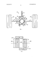
На фиг. 1 схематично показана карданная передача транспортного средства, включающая в себя узел дифференциала согласно одному из возможных вариантов осуществления изобретения;In FIG. 1 schematically shows a cardan transmission of a vehicle including a differential assembly according to one possible embodiment of the invention;
на фиг. 2 - разрез по плоскости, проходящей через первую и вторую полуосевые шестерни, и первую и вторую ведущие шестерни узла дифференциала на фиг. 1;in FIG. 2 is a section along a plane passing through the first and second half-axis gears, and the first and second driving gears of the differential assembly in FIG. one;
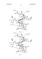
на фиг. 3 поясняется момент входа в зацепление первой полуосевой шестерни и первой ведущей шестерни, показанных на фиг. 2; иin FIG. 3, the timing of the engagement of the first semi-axial gear and the first drive gear shown in FIG. 2; and
на фиг. 4 поясняется момент входа в зацепление второй полуосевой шестерни и второй ведущей шестерни, показанных на фиг. 2.in FIG. 4, the timing of the engagement of the second semi-axial gear and the second drive gear shown in FIG. 2.
Варианты осуществления изобретенияEmbodiments of the invention
На фиг. 1 показана в качестве примера карданная передача транспортного средства, указанная в целом ссылочным обозначением 10. Приведенная в качестве примера карданная передача 10 транспортного средства предназначена для транспортного средства с задним приводом с дифференциалом с ограниченным проскальзыванием или, в общем, зубчатыми передачами.In FIG. 1 shows, by way of example, a cardan gear of a vehicle, indicated generally by the
Карданная передача 10, как правило, может включать в себя узел 20 дифференциала с ограниченным проскальзыванием с муфтовым узлом 22 и узлом или механизмом 24 дифференциала. Узел 20 дифференциала с ограниченным проскальзыванием обеспечивает привод пары полуосей 30 и 32, соединенных с ведущими колесами 40 и 42, соответственно. Как правило, при нормальных условиях работы узел 20 дифференциала с ограниченным проскальзыванием функционирует как обычный открытый дифференциал, до тех пор, пока не возникнет ситуация, при которой потребуется регулировка крутящего момента. При обнаружении или ожидании потери сцепления муфтовый узел 22 можно избирательно задействовать с целью генерирования оптимального для данной ситуации коэффициента регулировки.A universal
Кольцевая шестерня 48 может быть прикреплена к корпусу 50 узла 20 дифференциала. Кольцевая шестерня 48 может входить в зацепление для вращения совместно с ведущей шестерней 52 вала 54 ведущей шестерни. Как правило, вал 54 ведущей шестерни может приводиться от двигателя (не показан) с помощью трансмиссии (не показана). Вал 54 ведущей шестерни может передавать крутящий момент от ведущей шестерни 52 через ведомую шестерню 48 на картер 50 дифференциала.The
Кольцевая шестерня 48 жестко прикреплена к корпусу 50 дифференциала. Узел 24 дифференциала содержит первую и вторую полуосевые шестерни 60 и 62, установленные с возможностью вращения совместно с полуосями 30 и 32 (а также первым и вторым ведущими колесами 40 и 42, соответственно). Первый и второй валы 64 и 66 ведущих шестерен жестко прикреплены к корпусу 50 дифференциала 50 для вращения совместно с ним. Соответствующие первая и вторая ведущие шестерни 68 и 70 установлены с возможностью вращения вместе с валами 64, 66 и находятся в зацеплении с обеими полуосевыми шестернями 60 и 62. Несмотря на то, что на чертежах показаны только две ведущие шестерни, следует иметь в виду, что узел 24 дифференциала может включать в себя больше двух ведущих шестерен. В открытой конфигурации, более подробно раскрытой далее, узел 24 дифференциала позволяет полуосям 30 и 32 вращаться с разными скоростями.The
Муфтовый узел 22, в целом, может содержать пакет 72 муфты и привод муфты (не показан). Пакет 72 муфты содержит множество кольцевых пластин 74, установленных попеременно между несколькими кольцевыми фрикционными дисками 78. Множество кольцевых пластин 74 могут быть соединены с одним из двух элементов, а именно, либо с корпусом 50 дифференциала, либо с узлом 24 дифференциала, для вращения совместно с ним. Множество кольцевых фрикционных дисков 78 могут быть соединены с другим из вышеуказанных двух элементов, а именно, либо с корпусом 50 дифференциала, либо с узлом 24 дифференциала, для вращения совместно с ним.
Когда муфтовый узел 32 находится в открытом положении, несколько кольцевых пластин 74 и несколько кольцевых фрикционных дисков 78, установленных попеременно друг с другом, могут вращаться относительно друг друга, практически не контактируя друг с другом. Однако специалистам в данной области должно быть ясно, что используемое здесь выражение «не вступая в контакт» является условным и не означает, что кольцевые пластины 74 и кольцевые фрикционные диски 78 абсолютно не контактируют друг с другом, когда муфтовый узел 22 находится в открытом положении. Кольцевые пластины 74 и кольцевые фрикционные диски 78 могут перемещаться в направлении вдоль оси и вступать в сцепление друг с другом за счет сил трения, уменьшая тем самым движение вращения кольцевых пластин 74 и кольцевых фрикционных дисков 78 относительно друг друга, когда муфтовый узел 22 находится в своем закрытом или частично закрытом положении. Таким образом, когда муфтовый узел 22 находится в закрытом положении, полуосевые шестерни 60 и 62, так же, как и полуоси 30, 32 и ведущие колеса 40, 42, вращаются совместно.When the
Муфтовый узел 22 может работать в открытой конфигурации, в которой полуосевые шестерни 60 и 62 могут вращаться независимо друг от друга, например, с разными скоростями. Муфтовый узел 22 также может работать в закрытой или частично закрытой конфигурации, в которой полуосевые шестерни 60 и 62 вращаются совместно или частично совместно (т.е. не независимо друг от друга), например, с практически одинаковой скоростью. Муфтовый узел 22, например, может быть гидравлическим муфтовым узлом, в котором используется гидравлическая жидкость под давлением, действующая на поршень (не показан) привода муфты, чтобы избирательно переключать пакет 72 муфты между открытой, закрытой и частично закрытой конфигурациями. Возможны и другие конфигурации.
Далее со ссылками на фиг. 2-4 раскрыты дополнительные особенности узла 24 дифференциала. Первая полуосевая шестерня 60 установлена с возможностью вращения внутри корпуса 50 дифференциала и имеет первый внешний диаметр 100. Вторая полуосевая шестерня 62 установлена с возможностью вращения внутри корпуса 50 дифференциала и имеет второй внешний диаметр 102. Первый внешний диаметр 100 отличается от второго внешнего диаметра 102. В показанном примере второй внешний диаметр 102 меньше, чем первый внешний диаметр 100.Next, with reference to FIG. 2-4, additional features of the
Первая ведущая шестерня 68 находится в зацеплении для вращения с первой полуосевой шестерней 60 посредством первого зубчатого зацепления ПО (фиг. 2 и 3) в процессе первого зацепления. Вторая ведущая шестерня 70 находится в зацеплении для вращения со второй полуосевой шестерней 62 посредством второго зубчатого зацепления 112 (фиг. 2 и 4) в процессе второго зацепления. Первая и вторая ведущие шестерни 68, 70 образуют устройство для передачи крутящего момента между первой и второй ведущими шестернями 68, 70 и первой и второй полуосевыми шестернями 60, 62 для вращения первой и второй полуосевых шестерен 60, 62 относительно оси 120 вращения. Поскольку первый и второй внешние диаметры 100 и 102 разные, первое и второе зубчатые зацепления ПО и 112 также являются разными. В связи с этим, процессы зацепления смещены по времени.The
Как показано на фиг. 3, первая полуосевая шестерня 60 и первая ведущая шестерня 68 находятся в первом зубчатом зацеплении ПО в процессе первого зацепления. Первая полуосевая шестерня 60 содержит зубья 130 первой полуосевой шестерни, каждый из которых имеет вершину 132. Между соседними зубьями 130 первой полуосевой шестерни 60 расположены впадины 134. Первая полуосевая шестерня 60 расположена под углом 138 поворота. Первая ведущая шестерня 68 содержит зубья 150, каждый из которых имеет вершину 152. Между соседними зубьями 150 первой ведущей шестерни 68 расположены впадины 154. Взаимодействие зубьев первой полуосевой шестерни 60 и первой ведущей шестерни 68 происходит по линии 158 взаимодействия.As shown in FIG. 3, the first
Как показано на фиг. 4, вторая полуосевая шестерня 62 и вторая ведущая шестерня 70 находятся во втором зубчатом зацеплении 112 в процессе второго зацепления. Вторая полуосевая шестерня 62 содержит зубья 170 второй полуосевой шестерни, каждый из которых имеет вершину 172. Между соседними зубьями 170 второй полуосевой шестерни 62 расположены впадины 174. Вторая полуосевая шестерня 62 расположена под углом 178 поворота. Вторая ведущая шестерня 70 содержит зубья 190, каждый из которых имеет вершину 192. Между соседними зубьями 190 второй ведущей шестерни 70 расположены впадины 194. Взаимодействие зубьев второй полуосевой шестерни 62 и второй ведущей шестерни 70 происходит по линии 198 взаимодействия.As shown in FIG. 4, the second
Если полуосевые шестерни узла дифференциала имеют одинаковую геометрию, процессы их зацепления с соответствующими ведущими шестернями происходят одновременно. Иными словами, вершина зуба одной шестерни контактирует с впадиной между соответствующими зубьями другой шестерни, с которой она входит в зацепление, в каком-то определенном положении. Все ведущие шестерни имеют одну и ту же вышеупомянутую точку контакта при вращении. Ее положение определяется измеряемым в градусах углом поворота шестерни. Узел 24 дифференциала согласно изобретению обладает многими преимуществами по сравнению с узлами дифференциалов с шестернями одинаковой геометрии. Поскольку полуосевые шестерни 60 и 62 имеют различные диаметры, процессы зацепления полуосевых шестерен 60 и 62 с ведущими шестернями 68 и 70 смещены по времени относительно друг друга. Как уже было указано выше, несмотря на то, что на чертежах показаны только две ведущие шестерни, следует иметь в виду, что узел 24 дифференциала может включать в себя больше двух ведущих шестерен. Таким образом, процессы зацепления шестерен смещены по времени относительно друг друга. Коэффициент перекрытия, длина активной линии зацепления и момент контакта вершины зуба с впадиной для полуосевых шестерен 60 и 62 являются различными. При наличии в конструкции полуосевых шестерен 60, 62 разных диаметров процессы зацепления будут происходить в различных угловых положениях, в результате чего частоты моментов зацепления данных полуосевых шестерен 60, 62 будут слегка отличаться по фазе. Таким образом, процессы первого и второго зацепления не совпадают по фазе. В одном из возможных вариантов осуществления процессы первого и второго зацепления происходят с разницей в 2-4 градуса относительно друг друга. Узел 24 дифференциала может создавать пониженный уровень шума и амплитуды напряжений во время работы.If the semi-axial gears of the differential unit have the same geometry, the processes of their engagement with the corresponding drive gears occur simultaneously. In other words, the top of the tooth of one gear is in contact with the cavity between the corresponding teeth of the other gear with which it engages in a certain position. All pinion gears have the same aforementioned contact point during rotation. Its position is determined by the angle of rotation of the gear measured in degrees. The
Возвращаясь к фиг. 3, видно, что первая ведущая шестерня 68 содержит первый ряд зубьев 150 первой ведущей шестерни, каждый из которых имеет вершину 152. Серия первых контактов соответствующих вершин 152 зубьев первой ведущей шестерни с соответствующими зубьями 130 первой полуосевой шестерни 60 происходит в первую последовательность моментов времени контакта. Аналогичным образом, обращаясь к фиг. 4, видно, что вторая ведущая шестерня 70 содержит второй ряд зубьев 190 второй ведущей шестерни, каждый из которых имеет вершину 192. Серия вторых контактов соответствующих вершин 192 зубьев второй ведущей шестерни с соответствующими зубьями 190 второй полуосевой шестерни 62 происходит во вторую последовательность моментов времени контакта. Каждый момент времени первой последовательности моментов времени контакта смещен относительно каждого из моментов времени второй последовательности моментов времени контакта. Линия 158 взаимодействия отличается от линии 198 взаимодействия. Угол 138 поворота отличается от угла 178 поворота.Returning to FIG. 3, it can be seen that the
Приведенное выше описание предназначено для пояснения и раскрытия вариантов осуществления изобретения. Оно не является исчерпывающим и никоим образом не ограничивает сущность изобретения. Следует иметь в виду, что элементы или особенности согласно конкретному варианту осуществления изобретения, в целом, не ограничиваются данным конкретным вариантом осуществления, но могут быть взаимозаменяемыми (так, где это применимо) и могут использоваться в других вариантах осуществления изобретения, не рассмотренных и не раскрываемых в описании. Вышеупомянутые элементы и особенности могут быть изменены во многих отношениях. Такие изменения не должны рассматриваться как изменение сущности изобретения, и все такие модификации входят в объем изобретения.The above description is intended to explain and disclose embodiments of the invention. It is not exhaustive and in no way limits the essence of the invention. It should be borne in mind that the elements or features according to a particular embodiment of the invention, in General, are not limited to this particular embodiment, but can be used interchangeably (where applicable) and can be used in other embodiments of the invention, not considered and not disclosed in description. The above elements and features are subject to change in many ways. Such changes should not be construed as a change of the invention, and all such modifications are included in the scope of the invention.
Claims (42)
Applications Claiming Priority (3)
| Application Number | Priority Date | Filing Date | Title |
|---|---|---|---|
| US201461955295P | 2014-03-19 | 2014-03-19 | |
| US61/955,295 | 2014-03-19 | ||
| PCT/US2014/071892 WO2015142397A2 (en) | 2014-03-19 | 2014-12-22 | Non-synchronous gear meshing events for limited-slip differentials |
Publications (3)
| Publication Number | Publication Date |
|---|---|
| RU2016140939A RU2016140939A (en) | 2018-04-20 |
| RU2016140939A3 RU2016140939A3 (en) | 2018-06-19 |
| RU2675155C2 true RU2675155C2 (en) | 2018-12-17 |
Family
ID=52446426
Family Applications (1)
| Application Number | Title | Priority Date | Filing Date |
|---|---|---|---|
| RU2016140939A RU2675155C2 (en) | 2014-03-19 | 2014-12-22 | Non-synchronous gear meshing in limited-slip differentials |
Country Status (9)
| Country | Link |
|---|---|
| US (1) | US9863517B2 (en) |
| EP (1) | EP3120047B1 (en) |
| JP (1) | JP2017508930A (en) |
| KR (1) | KR102537272B1 (en) |
| CN (2) | CN204828543U (en) |
| AU (1) | AU2014386754B2 (en) |
| BR (1) | BR112016021189B1 (en) |
| RU (1) | RU2675155C2 (en) |
| WO (1) | WO2015142397A2 (en) |
Families Citing this family (4)
| Publication number | Priority date | Publication date | Assignee | Title |
|---|---|---|---|---|
| AU2014386754B2 (en) * | 2014-03-19 | 2019-01-03 | Eaton Intelligent Power Limited | Non-synchronous gear meshing events for limited-slip differentials |
| US10207582B2 (en) * | 2017-06-30 | 2019-02-19 | Shaeffler Technologies Ag & Co. Kg | Differential assembly with clutch |
| US10571008B2 (en) * | 2018-07-30 | 2020-02-25 | American Axle & Manufacturing, Inc. | Vehicle driveline component having a differential with asymmetric differential gearing |
| CN108825748B (en) * | 2018-08-23 | 2023-12-08 | 曹洪 | Differential mechanism capable of automatically limiting differential speed ratio and increasing torque |
Citations (3)
| Publication number | Priority date | Publication date | Assignee | Title |
|---|---|---|---|---|
| US808047A (en) * | 1905-09-29 | 1905-12-19 | Frank M Haldeman | Differential gearing. |
| DE3331535A1 (en) * | 1983-09-01 | 1984-02-23 | Daimler-Benz Ag, 7000 Stuttgart | Transfer box with at least one differential bevel pinion meshing with two side bevel gears |
| RU57683U1 (en) * | 2005-08-17 | 2006-10-27 | Вячеслав Иванович Крутин | VEHICLE DIFFERENTIAL |
Family Cites Families (12)
| Publication number | Priority date | Publication date | Assignee | Title |
|---|---|---|---|---|
| US1399045A (en) * | 1916-12-14 | 1921-12-06 | Bernstein Rudolf | Agricultural machine |
| US1687075A (en) * | 1927-06-06 | 1928-10-09 | Lloyd M Field | Variable-speed-transmission mechanism |
| US2962916A (en) * | 1958-05-28 | 1960-12-06 | Fwd Corp | Transfer case and center differential lock |
| US3548683A (en) * | 1968-11-29 | 1970-12-22 | Ford Motor Co | Differential gear mechanism with wobbling inertia ring |
| JPS5126977U (en) * | 1974-08-21 | 1976-02-27 | ||
| JPS6165940A (en) * | 1984-09-07 | 1986-04-04 | Tochigi Fuji Ind Co Ltd | Center differential gear |
| KR900700792A (en) * | 1987-12-18 | 1990-08-17 | 더 글리슨 워크스 | Improved Timing of Multi-Gear Thermal Automatic Devices |
| KR100345137B1 (en) * | 1999-12-30 | 2002-07-24 | 현대자동차주식회사 | Center differential |
| DE10309602B4 (en) * | 2003-03-05 | 2005-11-03 | Man Nutzfahrzeuge Ag | Differential of a motor vehicle |
| CN102192302A (en) * | 2010-03-09 | 2011-09-21 | 王焰 | Scattered gear differential mechanism |
| CN203404331U (en) * | 2013-08-23 | 2014-01-22 | 陕西汉德车桥有限公司 | Axle differential assembly between wheels |
| AU2014386754B2 (en) * | 2014-03-19 | 2019-01-03 | Eaton Intelligent Power Limited | Non-synchronous gear meshing events for limited-slip differentials |
-
2014
- 2014-12-22 AU AU2014386754A patent/AU2014386754B2/en not_active Ceased
- 2014-12-22 RU RU2016140939A patent/RU2675155C2/en active
- 2014-12-22 BR BR112016021189-8A patent/BR112016021189B1/en active IP Right Grant
- 2014-12-22 EP EP14833560.7A patent/EP3120047B1/en active Active
- 2014-12-22 JP JP2016557638A patent/JP2017508930A/en active Pending
- 2014-12-22 KR KR1020167028870A patent/KR102537272B1/en active IP Right Grant
- 2014-12-22 WO PCT/US2014/071892 patent/WO2015142397A2/en active Application Filing
-
2015
- 2015-03-18 CN CN201520154456.3U patent/CN204828543U/en active Active
- 2015-03-18 CN CN201510117914.0A patent/CN105179638B/en active Active
-
2016
- 2016-09-19 US US15/269,224 patent/US9863517B2/en active Active
Patent Citations (3)
| Publication number | Priority date | Publication date | Assignee | Title |
|---|---|---|---|---|
| US808047A (en) * | 1905-09-29 | 1905-12-19 | Frank M Haldeman | Differential gearing. |
| DE3331535A1 (en) * | 1983-09-01 | 1984-02-23 | Daimler-Benz Ag, 7000 Stuttgart | Transfer box with at least one differential bevel pinion meshing with two side bevel gears |
| RU57683U1 (en) * | 2005-08-17 | 2006-10-27 | Вячеслав Иванович Крутин | VEHICLE DIFFERENTIAL |
Also Published As
| Publication number | Publication date |
|---|---|
| BR112016021189A2 (en) | 2017-08-15 |
| CN105179638A (en) | 2015-12-23 |
| US9863517B2 (en) | 2018-01-09 |
| WO2015142397A3 (en) | 2016-02-18 |
| CN204828543U (en) | 2015-12-02 |
| US20170002909A1 (en) | 2017-01-05 |
| KR20160134788A (en) | 2016-11-23 |
| KR102537272B1 (en) | 2023-05-25 |
| AU2014386754B2 (en) | 2019-01-03 |
| EP3120047A2 (en) | 2017-01-25 |
| JP2017508930A (en) | 2017-03-30 |
| RU2016140939A3 (en) | 2018-06-19 |
| CN105179638B (en) | 2019-04-16 |
| BR112016021189B1 (en) | 2022-08-16 |
| EP3120047B1 (en) | 2021-03-03 |
| RU2016140939A (en) | 2018-04-20 |
| WO2015142397A2 (en) | 2015-09-24 |
| AU2014386754A1 (en) | 2016-10-13 |
Similar Documents
| Publication | Publication Date | Title |
|---|---|---|
| RU2675155C2 (en) | Non-synchronous gear meshing in limited-slip differentials | |
| CN108656868B (en) | Assembly with clutch collar and method of manufacture | |
| RU2392518C2 (en) | Differential block with active control of moments distribution | |
| US9624985B2 (en) | Coupling device for a motor vehicle | |
| RU2542807C2 (en) | Limited slip differential using face gears and differential housing | |
| AU2010277280A1 (en) | Locking differential having improved torque capacity | |
| US20160245382A1 (en) | Transmission with dual input and output shafts | |
| KR20120051696A (en) | Differential having self-adjusting gearing | |
| GB2473314A (en) | Gear reduction and coupling assembly | |
| CN105202143A (en) | Automotive power transmission device | |
| EP3277982B1 (en) | Cross-shaft for three pinion differential | |
| WO2022260634A1 (en) | Differential gearbox with output shafts that are on the same side and rotate in reverse directions | |
| WO2010097969A1 (en) | Coupling structure of snap ring for vehicle | |
| JP4779577B2 (en) | Differential equipment | |
| WO2010077173A1 (en) | Abik differential | |
| US11951829B2 (en) | Power transmission device | |
| KR101815128B1 (en) | Transfer Case of 2-Wheel/4-Wheel Driving Vehicle | |
| KR101538583B1 (en) | Transfer For 4Wheel Automobile | |
| SE2251505A1 (en) | A coupling arrangement | |
| RU2041406C1 (en) | Differential for vehicle | |
| RU2429143C1 (en) | Differential | |
| RU2029899C1 (en) | Differential of vehicle | |
| CN203686056U (en) | Differential gear train | |
| RU112103U1 (en) | EXCENTRIC DIFFERENTIAL | |
| JP2016070443A (en) | transmission |