RU2667018C1 - Method of calibration of track measuring devices - Google Patents
Method of calibration of track measuring devices Download PDFInfo
- Publication number
- RU2667018C1 RU2667018C1 RU2016138296A RU2016138296A RU2667018C1 RU 2667018 C1 RU2667018 C1 RU 2667018C1 RU 2016138296 A RU2016138296 A RU 2016138296A RU 2016138296 A RU2016138296 A RU 2016138296A RU 2667018 C1 RU2667018 C1 RU 2667018C1
- Authority
- RU
- Russia
- Prior art keywords
- calibration
- measuring
- track
- car
- rail
- Prior art date
Links
Images


Classifications
-
- E—FIXED CONSTRUCTIONS
- E01—CONSTRUCTION OF ROADS, RAILWAYS, OR BRIDGES
- E01B—PERMANENT WAY; PERMANENT-WAY TOOLS; MACHINES FOR MAKING RAILWAYS OF ALL KINDS
- E01B35/00—Applications of measuring apparatus or devices for track-building purposes
- E01B35/06—Applications of measuring apparatus or devices for track-building purposes for measuring irregularities in longitudinal direction
- E01B35/08—Applications of measuring apparatus or devices for track-building purposes for measuring irregularities in longitudinal direction for levelling
-
- E—FIXED CONSTRUCTIONS
- E01—CONSTRUCTION OF ROADS, RAILWAYS, OR BRIDGES
- E01B—PERMANENT WAY; PERMANENT-WAY TOOLS; MACHINES FOR MAKING RAILWAYS OF ALL KINDS
- E01B35/00—Applications of measuring apparatus or devices for track-building purposes
-
- E—FIXED CONSTRUCTIONS
- E01—CONSTRUCTION OF ROADS, RAILWAYS, OR BRIDGES
- E01B—PERMANENT WAY; PERMANENT-WAY TOOLS; MACHINES FOR MAKING RAILWAYS OF ALL KINDS
- E01B27/00—Placing, renewing, working, cleaning, or taking-up the ballast, with or without concurrent work on the track; Devices therefor; Packing sleepers
- E01B27/12—Packing sleepers, with or without concurrent work on the track; Compacting track-carrying ballast
- E01B27/13—Packing sleepers, with or without concurrent work on the track
- E01B27/16—Sleeper-tamping machines
- E01B27/17—Sleeper-tamping machines combined with means for lifting, levelling or slewing the track
-
- B—PERFORMING OPERATIONS; TRANSPORTING
- B61—RAILWAYS
- B61K—AUXILIARY EQUIPMENT SPECIALLY ADAPTED FOR RAILWAYS, NOT OTHERWISE PROVIDED FOR
- B61K9/00—Railway vehicle profile gauges; Detecting or indicating overheating of components; Apparatus on locomotives or cars to indicate bad track sections; General design of track recording vehicles
- B61K9/08—Measuring installations for surveying permanent way
-
- E—FIXED CONSTRUCTIONS
- E01—CONSTRUCTION OF ROADS, RAILWAYS, OR BRIDGES
- E01B—PERMANENT WAY; PERMANENT-WAY TOOLS; MACHINES FOR MAKING RAILWAYS OF ALL KINDS
- E01B33/00—Machines or devices for shifting tracks, with or without lifting, e.g. for aligning track, for shifting excavator track
-
- G—PHYSICS
- G01—MEASURING; TESTING
- G01C—MEASURING DISTANCES, LEVELS OR BEARINGS; SURVEYING; NAVIGATION; GYROSCOPIC INSTRUMENTS; PHOTOGRAMMETRY OR VIDEOGRAMMETRY
- G01C25/00—Manufacturing, calibrating, cleaning, or repairing instruments or devices referred to in the other groups of this subclass
- G01C25/005—Manufacturing, calibrating, cleaning, or repairing instruments or devices referred to in the other groups of this subclass initial alignment, calibration or starting-up of inertial devices
Abstract
Description
Изобретение относится к способу калибровки устройства для измерения рельсовых путей, содержащего по меньшей мере один согласованный с подъемным и рихтовальным приспособлением перемещаемый по рельсам путеизмерительный вагон и путеизмерительные датчики для измерения положения по высоте, направления и возвышения рельса рельсового пути, с машинной рамой в качестве эталонной нулевой линии, при этом путеизмерительный вагон снабжен поднимающим и опускающим путеизмерительный вагон приспособлением. Кроме того, предложено устройство для измерения рельсовых путей с калибровочным устройством. The invention relates to a method for calibrating a device for measuring rail tracks, comprising at least one track-measuring car moving along the rails and track gauges for measuring the height, direction and elevation of a rail of a rail track, with a machine frame as a reference zero lines, while the track-measuring car is equipped with a device raising and lowering the track-measuring car. In addition, a device for measuring rail tracks with a calibration device.
Шпалоподбивочные машины являются машинами для исправления положения рельсовых путей. Для этого используются измерительные системы, которые измеряют во время работы фактическое положение высоты рельсовых путей и фактическое положение направления рельсовых путей. С помощью агрегата подъема и рихтовки рельсовых путей рельсо-шпальная решетка поднимается и выправляется в боковом направлении и в этом положении фиксируется за счет уплотнения щебня под шпалами с помощью шпалоподбивочного агрегата. Измеренные фактические значения положения рельсовых путей сравниваются с заданными значениями положения рельсовых путей, которые вычисляются с помощью ведущего компьютера геометрии рельсовых путей в соответствии с планами заданного положения рельсовых путей управления железной дороги, и используются для управления и регулирования агрегата подъема и рихтовки рельсовых путей. При этом подъем и рихтовка рельсо-шпальной решетки осуществляются с помощью соответствующих гидравлических подъемных и рихтовальных цилиндров с пропорциональным или сенсорным управлением.Trowel machines are machines for correcting the position of rail tracks. To do this, measuring systems are used that during operation measure the actual position of the rail track height and the actual position of the rail track direction. With the help of the lifting and straightening unit of the rail tracks, the rail-sleeper lattice rises and straightens laterally and in this position is fixed by compacting crushed stone under the sleepers using a tamping unit. The measured actual values of the position of the rail tracks are compared with the set values of the position of the rail tracks, which are calculated using the master computer of the geometry of the rail tracks in accordance with the plans of the set position of the rail tracks of the railway control, and are used to control and regulate the lifting and straightening unit of the rail tracks. At the same time, the lifting and straightening of the rail-sleeper lattice are carried out using the corresponding hydraulic lifting and leveling cylinders with proportional or touch control.
Обычно используются измерительные установки со стальными хордами, соответственно, оптические измерительные установки. Стальные хорды обычно натянуты между тремя измерительными вагонами, при этом средний вагон несет датчик значения направления, который отклоняется хордой. Поскольку вблизи этого измерительного датчика находятся также необходимые для уплотнения рельсового пути подбивочные агрегаты, то хорда часто создает помехи в узких кривых. Для того чтобы подбивочные агрегаты не входили в контакт с хордой, хорды часто механически отклоняют в боковом направлении в точках натяжения, возникающая при этом погрешность измерения компенсируется электронно. Для измерения высотного положения рельсовых путей, над обоими рельсами натягиваются так называемые нивелирные троса. Обе измерительные точки над рельсами считываются в большинстве случаев с помощью датчиков угла (датчиков значения нивелирования). Нивелирные хорды должны быть расположены наверху, поскольку в нижней зоне находятся подбивочные агрегаты и тележки подбивочной машины. Эти хорды нивелирования протягиваются в кабины подбивочных агрегатов. На измерительных вагонах установлены датчики наклона, с целью измерения поперечного наклона рельсового пути.Typically used measuring devices with steel chords, respectively, optical measuring devices. Steel chords are usually stretched between three measuring cars, while the middle car carries a direction sensor that is deflected by the chord. Since knocking aggregates necessary for sealing the track are also located near this measuring sensor, the chord often creates interference in narrow curves. In order to prevent tamping units from coming into contact with the chord, the chords are often mechanically deflected laterally at the tension points, the measurement error arising in this case is compensated electronically. To measure the altitude of the rail tracks, so-called leveling cables are pulled over both rails. Both measuring points above the rails are read in most cases using angle sensors (leveling sensors). The leveling chords should be located at the top, since in the lower zone there are knocking units and trolleys of the knocker. These leveling chords extend into the cabs of the tamping units. Tilt sensors are installed on the measuring cars to measure the transverse tilt of the rail.
Измеренные с помощью датчиков измерения значений нивелирования, датчиков измерения значений направления и датчиков измерения значений возвышения отклонения преобразуются в электрический пропорциональный сигнал. Для управления шпалоподбивочной машиной решающее значение для точности каждого измерительного датчика являются величины масштабного фактора (например, в мВ/мм или мА/мм) и абсолютного нулевого положения измерительных датчиков. Для измерения этих значений необходима абсолютная калибровка. Под абсолютной калибровкой понимается здесь калибровка относительно прямой базовой линии для определения нулевого значения измерительного датчика. Это необходимо потому, что за счет конструктивного выполнения возникают неточности. Эти неточности суммируются из конструктивных механических допусков, неточного монтажа, механических зазоров, погрешностей в измерительной цепочке и т.д.Measured using sensors for measuring leveling values, sensors for measuring direction values and sensors for measuring elevation values, deviations are converted into an electrical proportional signal. For controlling the tamping machine, the critical factors for the accuracy of each measuring sensor are the scale factor (for example, in mV / mm or mA / mm) and the absolute zero position of the measuring sensors. Absolute calibration is required to measure these values. Absolute calibration refers here to calibration against a straight baseline to determine the zero value of the measuring sensor. This is necessary because inaccuracies arise due to constructive execution. These inaccuracies are summarized from structural mechanical tolerances, inaccurate installation, mechanical clearances, errors in the measuring chain, etc.
Проблемой является калибровка нуля измерительного датчика. Ниже приводится пояснение идеального случая. На идеально прямом рельсовом пути измерительные вагоны рихтовальной установки прижимаются поперек продольного направления рельсового пути к одной стороне рельса, а затем определяется нулевая точка измерительного датчика. Однако для рихтовальной установки необходимо также калибровать лежащую противоположно сторону.The problem is the zero calibration of the measuring sensor. The following is an explanation of the ideal case. On a perfectly straight rail track, the measuring cars of the leveling unit are pressed across the longitudinal direction of the rail track to one side of the rail, and then the zero point of the measuring sensor is determined. However, for a straightening installation, it is also necessary to calibrate the opposite side.
Для этого измерительный вагон на идеальном рельсовом пути (идеальный рельсовый путь: оба рельса образуют идеальные прямые с одинаковым расстоянием друг от друга и лежат точно в одной горизонтальной плоскости) необходимо прижимать к другому рельсу и определять нулевую точку для этой другой стороны. Это обусловлено тем, что направление рельсового пути всегда задается наружным в дуге рельсом, поскольку поезд направляется вдоль наружного в дуге рельса. Необходимость нулевой калибровки на обеих сторонах для датчика измерения направления получается за счет различных механических зазоров, различных размеров колеи измерительных вагонов и различных электронных путей измерения и т.д.To do this, the measuring car on an ideal rail track (ideal rail track: both rails form perfect straight lines with the same distance from each other and lie exactly in the same horizontal plane) must be pressed to the other rail and determine the zero point for this other side. This is due to the fact that the direction of the rail track is always specified by the rail external to the arc, since the train is guided along the rail external to the arc. The need for zero calibration on both sides for the direction measuring sensor is obtained due to various mechanical clearances, different track sizes of measuring cars and various electronic measuring paths, etc.
Однако идеального рельсового пути не существует. Рельсовый путь имеет погрешности продольной высоты, погрешности возвышения, скручивания, погрешности направления, а также погрешности ширины колеи. К этому добавляются различные проседания рельсового пути под нагрузкой. Поэтому для абсолютной калибровки нуля рельсового пути требуется так называемый «нулевой рельсовый путь». Для этого выбирается участок рельсового пути, имеющий по меньшей мере длину применяемой для выравнивания измерительной установки, который имеет возможно меньшие погрешности рельсового пути указанного выше вида. Поскольку требуемые неточности выравнивания лежат ниже 1 мм, то реальные рельсовые пути для этого не достаточны. Поэтому перед собственно выравниванием необходимо точно измерять положение рельсового пути с помощью геодезических измерительных приборов или с помощью других методов (с использованием шнуровой хорды). Затем шпалоподбивочная машина наезжает на этот рельсовый путь. Определяемые с помощью геодезических методов или с помощью других методов погрешности рельсового пути компенсируются затем с помощью распорок под измерительными колесами для высоты, соответственно, между гребнями колеса и рельсом. Затем выполняют калибровку нуля. Измерение положения рельсового пути осуществляется, как правило, на реальном рельсовом пути без нагрузки. За счет нагрузки шпалоподбивочной машиной могут происходить неизвестные прогибы рельс и рельсо-шпальной решетки, что оказывает отрицательное влияние на точность калибровки. Надежней является неподвижно забетонированный рельсовый путь, однако его обычно не найти на свободном участке. Поэтому применяемые методы калибровки нуля являются дорогостоящими, требующими затрат времени, лишь условно точными и могут выполняться лишь квалифицированным персоналом. Проверка измерительной системы на железнодорожном перегоне водителем машины практически невозможна.However, an ideal rail track does not exist. The rail track has errors of longitudinal height, elevation, twisting errors, direction errors, and track width errors. To this are added various rail subsidence under load. Therefore, for absolute zero calibration of a rail track, a so-called “zero rail track” is required. For this, a section of the rail track is selected that has at least the length of the measuring installation used for leveling, which has the smallest possible errors of the rail track of the type indicated above. Since the required alignment inaccuracies lie below 1 mm, real rail tracks are not sufficient for this. Therefore, before alignment itself, it is necessary to accurately measure the position of the rail track using geodetic measuring instruments or using other methods (using a cord chord). Then the tamping machine bumps onto this rail track. The rail errors determined using geodetic methods or other methods are then compensated by using spacers under the measuring wheels for the height, respectively, between the wheel flanges and the rail. Then perform a zero calibration. Measurement of the position of the rail track is carried out, as a rule, on a real rail track without load. Due to the load of the tamping machine, unknown deflections of the rail and the rail-sleeper lattice can occur, which negatively affects the accuracy of the calibration. More reliably is a motionlessly concreted rail track, but it is usually not found in a free area. Therefore, the methods used to calibrate zero are expensive, time-consuming, only conditionally accurate and can only be performed by qualified personnel. Verification of the measuring system on a railroad stage by the driver of the machine is practically impossible.
Таким образом, в основе изобретения лежит задача создания калибровочного устройства указанного в начале вида, которое предотвращает неточности и обеспечивает простую и быструю калибровку.Thus, the basis of the invention is the task of creating a calibration device indicated at the beginning of the form, which prevents inaccuracies and provides a simple and quick calibration.
Задача решена, согласно изобретению, тем, что предусмотрено согласованное с рамой машины калибровочное устройство, при этом путеизмерительный вагон для калибровки датчиков положения рельсового пути сначала опускается из поднятого с рельсового пути положения парковки на рельсовый путь или в промежуточное положение, после чего калибровочные упоры с помощью сервопривода перемещаются из положения покоя в положение калибровки, при этом к калибровочным упорам в дальнейшем поднимается и приставляется путеизмерительный вагон, после чего считываются получаемые значения датчиков измерения рельсового пути и вводятся в качестве калибровочного значения в измерительную установку и запоминаются, после чего путеизмерительный вагон опускается на рельсовый путь, и затем калибровочные упоры при необходимости пермещаются с помощью сервопривода из своего калибровочного положения в свое положение покоя.The problem is solved, according to the invention, in that a calibration device is provided that is compatible with the machine frame, while the track measuring car for calibrating the rail position sensors is first lowered from the parking position raised from the rail to the rail track or to an intermediate position, after which the calibration stops are made using the servos move from the resting position to the calibration position, while the track gauge is subsequently lifted and attached to the calibration stops, after which The obtained values of the track measuring sensors are poured and entered as a calibration value into the measuring unit and stored, after which the track measuring car is lowered onto the track, and then the calibration stops, if necessary, are moved from their calibration position to their rest position by means of a servo drive.
Согласно изобретению, машинная рама образует эталон абсолютного нуля. На машинной раме предусмотрены перемещаемые с помощью гидравлических калибровочных цилиндров между положением покоя и положением калибровки калибровочные упоры для измерительного вагона (измерительных вагонов), предпочтительно три калибровочных упора. Калибровочные упоры расположены слева и справа, т.е. на обеих сторонах, на машинной раме в зоне измерительных вагонов и, в частности, с возможностью регулирования относительно их положения по высоте. Эти калибровочные упоры после изготовления машины точно измеряются и настраиваются с помощью юстировочных приспособлений. Перед настройкой нуля водитель машины перемещает шпалоподбивочную машину на относительно плоский прямой рельсовый путь, с целью предотвращения скручивания машинной рамы. Затем для настройки абсолютного нуля измерительной системы измерительные вагоны с помощью приспособления для подъема и опускания измерительных вагонов опускаются в нижнее положение (например, опускаются на рельсы). Затем калибровочные упоры перемещаются из своего положения покоя в свое положение калибровки. Затем измерительные вагоны поднимаются и прижимаются к калибровочным упорам с заданной силой. При этом, в частности, ходовые ролики измерительного вагона прижимаются к согласованным калибровочным упорам. Получаемые при этом данные датчиков считываются и сохраняются в измерительной установке. Эта измерительная установка содержит обычно вычислительный блок с согласованными блоками памяти для оценки измерительных данных. According to the invention, the machine frame forms an absolute zero standard. On the machine frame, calibration stops for the measuring car (s), preferably three calibration stops, are moved between the rest position and the calibration position by means of hydraulic calibration cylinders. Calibration stops are located on the left and right, i.e. on both sides, on a machine frame in the area of the measuring cars and, in particular, with the possibility of regulation relative to their height position. After calibration, these calibration stops are accurately measured and adjusted using adjustment devices. Before setting the zero, the driver of the machine moves the tamping machine on a relatively flat straight rail track, in order to prevent twisting of the machine frame. Then, to set the absolute zero of the measuring system, the measuring cars with the device for raising and lowering the measuring cars are lowered to the lower position (for example, lowered onto the rails). The calibration stops then move from their rest position to their calibration position. Then the measuring cars are lifted and pressed against the calibration stops with a given force. In this case, in particular, the running rollers of the measuring car are pressed against the agreed calibration stops. The resulting sensor data is read and stored in the measuring installation. This measurement setup typically contains a computing unit with matched memory blocks for evaluating the measurement data.
При этом, в частности, рекомендуется, что путеизмерительный вагон в положении калибровки сначала на первом этапе прижимается на стороне машинной рамы в направлении поперечной оси путеизмерительного вагона с помощью прижимного устройства гребнем колеса к согласованному калибровочному упору, и считывается получаемое значение датчика измерения установочного значения и датчика нивелирования в качестве значения калибровки нуля для этой стороны машинной рамы в измерительную установку и запоминаются там, и когда путеизмерительный вагон затем на втором этапе на другой, противоположно лежащей стороне машинной рамы прижимается в противоположном направлении поперечной оси путеизмерительного вагона с помощью прижимного приспособления гребнем колеса к согласованному калибровочному упору, то получаемое значение датчика измерения установочного значения считывается и запоминается в измерительную установку в качестве значения калибровки нуля для этой стороны машинной рамы. Сначала ходовые ролики соответствующего измерительного вагона, т.е. на одной стороне машины, прижимаются к калибровочным упорам. Осуществляется калибровка нуля этой стороны для направления. Поскольку измерительные колеса являются цилиндрическими, то можно одновременно осуществлять калибровку датчика нивелирования. После прижимания измерительных колес к противоположно лежащим упорам на другой стороне машины осуществляется настройка нуля датчика установочного значения для этой стороны. После опускания измерительного вагона на рельсовый путь калибровочные упоры снова поворачиваются наружу. Получаемому при калибровке на измерительном вагоне фактическому значению возвышения присваивается значение измеряемого на машинной раме эталонного возвышения.In this case, in particular, it is recommended that the track gauge car in the calibration position is first pressed on the side of the machine frame in the direction of the transverse axis of the track gauge with the clamping device with the wheel flange against the agreed calibration stop, and the obtained value of the setting value measurement sensor and the sensor is read leveling as a zero calibration value for this side of the engine frame into the measuring unit and are stored there, and when the measuring car Then, at the second stage, on the opposite side of the engine frame, it is pressed in the opposite direction of the transverse axis of the track car using the wheel flange clamping device to the agreed calibration stop, the obtained value of the sensor for measuring the set value is read and stored in the measuring unit as a zero calibration value for this side of the engine frame. First, the rollers of the corresponding measuring car, i.e. on one side of the machine, pressed against the calibration stops. Zero calibration is performed on this side for direction. Since the measuring wheels are cylindrical, it is possible to simultaneously calibrate the leveling sensor. After the measuring wheels are pressed against the opposite stops on the other side of the machine, the zero value of the setpoint sensor for this side is adjusted. After lowering the measuring car onto the rail track, the calibration stops again turn outward. The actual elevation value obtained during calibration on the measuring car is assigned the value of the standard elevation measured on the machine frame.
Этапы способа предпочтительно выполняются автоматизированно программой управления.The steps of the method are preferably performed automatically by a control program.
Предпочтительно, в этом варианте выполнения изобретения отпадает необходимость в «нулевом рельсовом пути» и обеспечивается возможность автоматической, быстрой, абсолютной и точной калибровки нуля измерительной системы на реальном плоском участке. Калибровка нуля может осуществляться водителем машины на месте. Весь процесс измерения можно выполнять автоматически. Таким образом, можно быстро проверять работоспособность измерительной системы и ее точность перед началом работы на обрабатываемом участке. Другие преимущества обеспечиваются тем, что для калибровки персонал не должен ходить по рельсовому пути, поскольку это часто связано с опасностью за счет движения по соседнему рельсовому пути. Кроме того, изобретение имеет чрезвычайно большой потенциал уменьшения стоимости и повышает безопасность работы шпалоподбивочной машины.Preferably, in this embodiment of the invention, there is no need for a “zero track” and the possibility of automatic, fast, absolute and accurate zero calibration of the measuring system on a real flat area is provided. Zero calibration can be done by the driver on the spot. The entire measurement process can be performed automatically. Thus, it is possible to quickly check the operability of the measuring system and its accuracy before starting work on the treated area. Other advantages are ensured by the fact that personnel do not have to walk along the track for calibration, as this is often associated with danger due to movement along a neighboring track. In addition, the invention has an extremely large potential for reducing costs and increases the safety of the tamping machine.
На чертежах показан в качестве примера предмет изобретения, а именно:The drawings show as an example the subject of the invention, namely:
фиг.1 - шпалоподбивочная машина со шпалоподбивочным агрегатом, агрегатом подъема и рихтовки рельсового пути, измерительной системой нивелирования и системой рихтовки рельсового пути, на виде сбоку;figure 1 - tamper machine with tamper unit, a unit for lifting and straightening the track, a measuring leveling system and a system of straightening the track, in side view;
фиг.2 - калибровочное устройство, согласно изобретению, с измерительным вагоном в разрезе;figure 2 - calibration device, according to the invention, with a measuring car in section;
фиг.3 - часть фиг. 2 с калибровочным упором, в увеличенном масштабе;FIG. 3 is a part of FIG. 2 with a calibration stop, on an enlarged scale;
фиг.4 - схема измерительной установки нивелирования с эталонной линией в виде машинной рамы и эталонной линией калибровки, а также с калибровочными упорами; и4 is a diagram of a measuring leveling installation with a reference line in the form of a machine frame and a reference calibration line, as well as with calibration stops; and
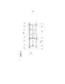
фиг.5 - схема измерительной установки рихтовки с эталонной линией в виде машинной рамы и эталонной линией калибровки, а также с калибровочными упорами слева и справа машинной рамы.5 is a diagram of a measuring installation of straightening with a reference line in the form of a machine frame and a reference calibration line, as well as with calibration stops on the left and right of the machine frame.
Шпалоподбивочная машина 1 (см. фиг.1) имеет шпалоподбивочный агрегат 26 и агрегат 25 подъема и рихтовки. Машинная рама 13 служит для калибровки абсолютного нуля в качестве эталона. Рихтовочная установка состоит из стальной направляющей хорды 12, трех измерительных вагонов 4 и датчика 11 измерения направления. Установка нивелирования состоит из двух стальных хорд 16, которые натянуты над рельсами, двух датчиков 17 нивелирования с приемными щупами 19 для стальной хорды и нивелировочными штангами 14. Шпалоподбивочная машина 1 перемещается с помощью ходовых частей по рельсам 3.The tamping machine 1 (see FIG. 1) has a tamping unit 26 and a lifting and straightening unit 25.
В качестве датчиков положения рельсового пути для измерения рельс рельсового пути (3, 28) предусмотрены датчики для измерения положения по высоте, датчики 17 нивелирования, направления, датчики 11 направлении, и возвышения, датчики 25 наклона. С путеизмерительным вагоном 4 согласовано приспособление 9 для подъема и опускания измерительного вагона.As sensors of the position of the rail track for measuring the rail of the rail track (3, 28), sensors are provided for measuring the position in height, leveling
С машинной рамой 13 сопряжено калибровочное устройство 2 с калибровочными упорами 5, которые в поднятом с рельсового пути положении парковки, при опущенном на рельсовый путь или в промежуточное положение путеизмерительном вагоне 4 для калибровки путеизмерительных датчиков установлены с возможностью перемещения посредством сервопривода из положения покоя в положение калибровки и к которым в дальнейшем могут приподниматься или приставляться путеизмерительный вагон 4. Калибровочные упоры 5 образуют точки упора для измерительного вагона, приставляемого с помощью приспособления 9 для подъема измерительного вагона к калибровочным упорам 5 (см. фиг.2).
В одном варианте выполнения устройства 2 абсолютной калибровки (см. фиг.2), машинная рама 13 служит в качестве исходного эталона. На машинной раме установлены соосно устанавливаемые в продольном направлении калибровочные упоры 7 (например, с резьбовой перестановкой и фиксацией с помощью контргайки). До этих упоров поворачиваются и отворачиваются калибровочные рычаги с калибровочными упорами 5 с помощью калибровочных цилиндров 8, т.е. из своего положения покоя в свое положение калибровки. С помощью регулировочного приспособления 6 (резьбовой трубы, которая соединяет верхнее и нижнее рычажное плечо с помощью резьбы, при этом сверху находится, например, левая резьба, а внизу - правая резьба), можно юстировать положение по высоте калибровочного упора 5. Измерительное колесо 4 с помощью цилиндра 9 для подъема измерительного вагона прижимается вверх и с помощью прижимных цилиндров 10 сбоку к соответствующему калибровочному упору 5. На измерительном вагоне установлен датчик 11 измерения направления, который с помощью поводка измеряет боковое положение направляющего троса 12. На измерительном вагоне находится также датчик 25 наклона. В качестве эталона для этого датчика наклона на машинной раме 13 находится эталонный датчик 23 наклона. Для прижимания слева оба цилиндра для подъема измерительного вагона переключаются на «подъем» (силы FLH и FRH действуют вверх), и левый прижимной цилиндр переключается для выполнения прижимания (сила FLA), а правый прижимной цилиндр выключается. Для настройки правой стороны в правый цилиндр подается давление (сила FRA), а левый прижимной цилиндр выключается. Рельсы 3 смонтированы на шпалах 28.In one embodiment of the absolute calibration device 2 (see FIG. 2), the
Калибровочный упор 5 прилегает сбоку к точке соприкосновения на высоте D (обычно 14 мм) (см. фиг.3). При этом действуют горизонтальная сила FQ и вертикальная сила FV.The
На фиг.4 показана схематично система нивелирования, которая состоит из нивелировочных штанг 14, датчика 18 нивелирования, поводка 19, нивелировочного троса 16, приспособления 18 для натяжения троса и измерительного вагона 4. Эталонная линия 15 калибровочного устройства абсолютного нуля, согласно изобретению, лежит параллельно эталонной линии 15 машины. По высоте колеса 4 прижимаются к калибровочным упорам 5. Дефект 20 рельсового пути наглядно показывает, что калибровка с опущенным на рельсовый путь 3 измерительным вагоном 4 была бы ошибочной.Figure 4 shows schematically the leveling system, which consists of leveling
На фиг.5 схематично показан вариант выполнения, согласно изобретению, калибровки абсолютного нуля для установки измерения направления. Измерительные колеса 4 прижаты сверху к калибровочным упорам 5. Эталонные линии калибровочного устройства (штрихпунктирные линии) параллельны эталонной линии 22 машины. Позицией 24 обозначено механическое приспособление для боковой перестановки троса, которое может применяться для определения масштабного фактора. На среднем измерительном вагоне 4 установлен датчик 11 измерения направления, который измеряет боковое отклонение направляющего троса 12. Направляющий трос 12 натягивается с помощью натяжного приспособления 18. При выполнении калибровки нуля с опущенными на рельсовый путь 3 измерительными вагонами 4, она имела бы погрешность, равную дефекту 21 рельсового пути.5 schematically shows an embodiment according to the invention of absolute zero calibration for setting a direction measurement. The measuring
Claims (5)
Applications Claiming Priority (3)
| Application Number | Priority Date | Filing Date | Title |
|---|---|---|---|
| ATA50901/2014 | 2014-12-12 | ||
| ATA50901/2014A AT516248B1 (en) | 2014-12-12 | 2014-12-12 | Method for calibrating a device for measuring tracks |
| PCT/AT2015/050313 WO2016090401A1 (en) | 2014-12-12 | 2015-12-10 | Method for calibrating a device for measuring tracks |
Publications (1)
| Publication Number | Publication Date |
|---|---|
| RU2667018C1 true RU2667018C1 (en) | 2018-09-13 |
Family
ID=55069639
Family Applications (1)
| Application Number | Title | Priority Date | Filing Date |
|---|---|---|---|
| RU2016138296A RU2667018C1 (en) | 2014-12-12 | 2015-12-10 | Method of calibration of track measuring devices |
Country Status (6)
| Country | Link |
|---|---|
| US (1) | US10174461B2 (en) |
| EP (1) | EP3230526B1 (en) |
| CN (1) | CN106489006B (en) |
| AT (1) | AT516248B1 (en) |
| RU (1) | RU2667018C1 (en) |
| WO (1) | WO2016090401A1 (en) |
Families Citing this family (16)
| Publication number | Priority date | Publication date | Assignee | Title |
|---|---|---|---|---|
| DK3390723T3 (en) * | 2015-12-17 | 2020-04-27 | Siemens Mobility Pty Ltd | Rail track displacement measurement system and proactive maintenance approach |
| AT519218B1 (en) * | 2017-02-06 | 2018-05-15 | Hp3 Real Gmbh | Method for optimizing a track position |
| CN107190597A (en) * | 2017-07-20 | 2017-09-22 | 中国水利水电第五工程局有限公司 | A kind of Ballast track quick multifunctional construction equipment |
| CN110130167A (en) * | 2018-02-08 | 2019-08-16 | 中国铁建高新装备股份有限公司 | A kind of railroad track geometric parameter measurement device and play track lining control method |
| CN109353371B (en) * | 2018-12-12 | 2023-11-10 | 湖南高创海捷工程技术有限公司 | Full-automatic steel rail non-contact profile detection device |
| CN113008271A (en) * | 2019-08-15 | 2021-06-22 | 深圳市瑞立视多媒体科技有限公司 | Mathematical model construction method for calibrating 3D rotation difference, calibration method and device thereof |
| CN112442927A (en) * | 2019-09-02 | 2021-03-05 | 中国铁道科学研究院集团有限公司铁道建筑研究所 | Method for measuring front end deviation of tamping car |
| CN110924247A (en) * | 2019-12-11 | 2020-03-27 | 楼文昊 | I-shaped steel rail calibration and alignment device for railway construction |
| CN111024144A (en) * | 2019-12-20 | 2020-04-17 | 中国铁建重工集团股份有限公司 | Calibration table for detection equipment |
| AT523691B1 (en) | 2020-04-07 | 2022-03-15 | Hp3 Real Gmbh | Procedure for calibrating a machine's own measuring system |
| AT17147U1 (en) * | 2020-05-04 | 2021-07-15 | Hp3 Real Gmbh | Process for generating a safety-relevant acceptance letter for a track maintenance machine |
| AT523717B1 (en) * | 2020-06-18 | 2021-11-15 | Hp3 Real Gmbh | Method for measuring a track position |
| CN111926640B (en) * | 2020-08-14 | 2021-09-28 | 北京中建空列集团有限公司 | Movable suspension type air train track maintenance system |
| CN113460114B (en) * | 2021-07-14 | 2022-06-28 | 中南大学 | Railway fastener structure damage detection vehicle |
| CN113587873B (en) * | 2021-07-21 | 2023-04-25 | 江西日月明测控科技股份有限公司 | Floating pressing device and rail inspection equipment |
| AT525354B1 (en) * | 2022-06-10 | 2023-03-15 | Plasser & Theurer Export Von Bahnbaumaschinen Gmbh | Method and system for calibrating a railroad scale |
Citations (5)
| Publication number | Priority date | Publication date | Assignee | Title |
|---|---|---|---|---|
| DE4102871A1 (en) * | 1990-02-06 | 1991-08-08 | Plasser Bahnbaumasch Franz | TRACKING MACHINE |
| RU2097471C1 (en) * | 1993-11-05 | 1997-11-27 | Франц Плассер Банбаумашинен-Индустригезельшафт Мбх | Track liner |
| RU2151705C1 (en) * | 1998-01-06 | 2000-06-27 | Акционерное общество "Кузнецкий металлургический комбинат" | Rail straightness checking device |
| WO2005103385A1 (en) * | 2004-04-21 | 2005-11-03 | J. Müller AG | Method for measuring tracks |
| RU91321U1 (en) * | 2009-03-27 | 2010-02-10 | Закрытое акционерное общество "Фирма ТВЕМА" | MOBILE DIAGNOSTIC COMPLEX OF AUTOMATED ASSESSMENT OF THE CONDITION OF OBJECTS OF RAILWAY INFRASTRUCTURE |
Family Cites Families (32)
| Publication number | Priority date | Publication date | Assignee | Title |
|---|---|---|---|---|
| CH643618A5 (en) * | 1981-09-25 | 1984-06-15 | Sig Schweiz Industrieges | RAILWAY SITE MACHINE. |
| AT382410B (en) * | 1983-11-16 | 1987-02-25 | Plasser Bahnbaumasch Franz | DEVICE FOR CORRECTING THE HIGH ALTITUDE AND CROSS-TILTING OF A TRACK |
| ATE33411T1 (en) * | 1985-08-22 | 1988-04-15 | Plasser Bahnbaumasch Franz | TRACK MOBILE MACHINE FOR MEASURING OR. REGISTER OR CORRECT THE TRACK POSITION WITH LASER BEAM OR -LEVELS. |
| AT400162B (en) | 1990-02-06 | 1995-10-25 | Plasser Bahnbaumasch Franz | METHOD AND TRACKING MACHINE FOR MEASURING THE CROSS SHIFTING RESISTANCE |
| AT402953B (en) * | 1990-11-12 | 1997-10-27 | Plasser Bahnbaumasch Franz | DEVICE FOR CONTACTLESS TRACK WIDTH MEASUREMENT OF RAILS |
| US5172637A (en) * | 1991-02-01 | 1992-12-22 | Franz Plasser Bahnbaumaschinen-Industriegesellschaft M.B.H. | Track surfacing machine for the controlled lowering of the track |
| AT403066B (en) * | 1991-07-12 | 1997-11-25 | Plasser Bahnbaumasch Franz | METHOD FOR DETERMINING THE DEVIATIONS OF THE ACTUAL LOCATION OF A TRACK SECTION |
| EP0930398A1 (en) * | 1998-01-19 | 1999-07-21 | Franz Plasser Bahnbaumaschinen-Industriegesellschaft m.b.H. | Correction method for the position of a railway track |
| JP3905972B2 (en) * | 1998-02-27 | 2007-04-18 | 有限会社ユーパス | Orbital displacement measurement system |
| DK0952254T3 (en) * | 1998-03-27 | 2004-03-15 | Plasser Bahnbaumasch Franz | Method for track position correction |
| DE50015765D1 (en) * | 1999-02-12 | 2009-12-03 | Plasser Bahnbaumasch Franz | Method for measuring a track |
| CN2394951Y (en) * | 1999-09-06 | 2000-09-06 | 乔根清 | Multifunction detector for railway rail |
| AT3877U3 (en) * | 2000-06-09 | 2001-03-26 | Plasser Bahnbaumasch Franz | STAMPING MACHINE |
| US6674023B2 (en) * | 2001-11-13 | 2004-01-06 | Alan Paine | Method and apparatus for weighing railroad cars |
| CN2543980Y (en) * | 2002-06-05 | 2003-04-09 | 王智强 | Ruil track dectector |
| AT5982U3 (en) * | 2002-11-13 | 2003-12-29 | Plasser Bahnbaumasch Franz | METHOD FOR SCANNING A BED PROFILE |
| US7007561B1 (en) * | 2002-12-31 | 2006-03-07 | Holland L.P. | Gauge restraint measurement system |
| RU2266225C1 (en) * | 2004-04-13 | 2005-12-20 | Горделий Виталий Иванович | Rail track mobile testing device |
| US8958079B2 (en) * | 2004-06-30 | 2015-02-17 | Georgetown Rail Equipment Company | System and method for inspecting railroad ties |
| US7403296B2 (en) * | 2004-11-05 | 2008-07-22 | Board Of Regents Of University Of Nebraska | Method and apparatus for noncontact relative rail displacement, track modulus and stiffness measurement by a moving rail vehicle |
| DE102007051126A1 (en) * | 2007-10-24 | 2009-04-30 | Bombardier Transportation Gmbh | Determination of the remaining service life of a vehicle component |
| CN201158385Y (en) * | 2008-02-25 | 2008-12-03 | 长沙悦诚机电科技有限公司 | Instrument for accurately testing high-speed railway rails |
| DE102008060188A1 (en) * | 2008-11-28 | 2010-06-10 | Siemens Aktiengesellschaft | Method and device for distance measurement |
| DE102010047234B8 (en) * | 2010-10-04 | 2015-12-24 | Schenck Process Gmbh | Weighing module for measuring wheel contact forces |
| US8844149B2 (en) * | 2011-09-13 | 2014-09-30 | Holland, L.P. | Rail cant measurement tool and method |
| US9303364B2 (en) * | 2012-09-13 | 2016-04-05 | Holland, L.P. | Rail cant measurement tool and method |
| US20140151460A1 (en) * | 2012-12-02 | 2014-06-05 | General Electric Company | System and method for maintaining sensor performance |
| US9573607B2 (en) * | 2013-03-15 | 2017-02-21 | Kanawha Scales & Systems, Inc. | System for accurate measurement of vehicle speeds for low speed industrial applications |
| SE538909C2 (en) * | 2014-04-15 | 2017-02-07 | Eber Dynamics Ab | Method and apparatus for determining structural parameters of a railway track |
| EP2957674B1 (en) * | 2014-06-18 | 2017-10-11 | HP3 Real GmbH | Method for operating a movable superstructure machine on a railway track |
| US9533698B2 (en) * | 2014-09-24 | 2017-01-03 | Bartlett & West, Inc. | Railway monitoring system |
| US10000223B2 (en) * | 2015-09-18 | 2018-06-19 | Tech Services Group, LLC | Rail track geometry measurement |
-
2014
- 2014-12-12 AT ATA50901/2014A patent/AT516248B1/en active
-
2015
- 2015-12-10 CN CN201580024487.XA patent/CN106489006B/en active Active
- 2015-12-10 EP EP15820027.9A patent/EP3230526B1/en active Active
- 2015-12-10 US US15/319,760 patent/US10174461B2/en active Active
- 2015-12-10 WO PCT/AT2015/050313 patent/WO2016090401A1/en active Application Filing
- 2015-12-10 RU RU2016138296A patent/RU2667018C1/en active
Patent Citations (5)
| Publication number | Priority date | Publication date | Assignee | Title |
|---|---|---|---|---|
| DE4102871A1 (en) * | 1990-02-06 | 1991-08-08 | Plasser Bahnbaumasch Franz | TRACKING MACHINE |
| RU2097471C1 (en) * | 1993-11-05 | 1997-11-27 | Франц Плассер Банбаумашинен-Индустригезельшафт Мбх | Track liner |
| RU2151705C1 (en) * | 1998-01-06 | 2000-06-27 | Акционерное общество "Кузнецкий металлургический комбинат" | Rail straightness checking device |
| WO2005103385A1 (en) * | 2004-04-21 | 2005-11-03 | J. Müller AG | Method for measuring tracks |
| RU91321U1 (en) * | 2009-03-27 | 2010-02-10 | Закрытое акционерное общество "Фирма ТВЕМА" | MOBILE DIAGNOSTIC COMPLEX OF AUTOMATED ASSESSMENT OF THE CONDITION OF OBJECTS OF RAILWAY INFRASTRUCTURE |
Also Published As
| Publication number | Publication date |
|---|---|
| CN106489006A (en) | 2017-03-08 |
| AT516248A4 (en) | 2016-04-15 |
| US20170268180A1 (en) | 2017-09-21 |
| EP3230526A1 (en) | 2017-10-18 |
| EP3230526B1 (en) | 2018-11-21 |
| CN106489006B (en) | 2019-05-28 |
| US10174461B2 (en) | 2019-01-08 |
| WO2016090401A1 (en) | 2016-06-16 |
| AT516248B1 (en) | 2016-04-15 |
Similar Documents
| Publication | Publication Date | Title |
|---|---|---|
| RU2667018C1 (en) | Method of calibration of track measuring devices | |
| CN105200877B (en) | Track calibration system | |
| SU1259963A3 (en) | Movable straightening-ramming machine | |
| JP7305648B2 (en) | Track-building machines and methods for adjusting track height | |
| RU2674726C1 (en) | Method and device for compaction of broken stone underlayer of railway track | |
| US20200347557A1 (en) | Method for track position improvement by means of a track-movable track-tamping machine | |
| JP3609861B2 (en) | Track work machine for track position correction | |
| EP3376184A2 (en) | Apparatus and method for calibrating a weigh-in-motion sensor | |
| SK1592000A3 (en) | Correction method for the position of a railway track | |
| RU2669658C1 (en) | Tamper for way ballast layer sealing | |
| CN103410062A (en) | Method for constructing monolithic roadbed by using single railway tunnel bracket type steel rail way | |
| DE3444723C2 (en) | ||
| CN209851191U (en) | Single track PC roof beam template of high accuracy | |
| EP4133129B1 (en) | Method for calibrating a machine-integrated measuring system | |
| CN211340423U (en) | Concrete spreading trestle | |
| CN203440723U (en) | Ballastless track bed plate elevation rapid detection vehicle | |
| US3212451A (en) | Surface sensing device | |
| RU2468136C1 (en) | Method for railway track sleeper tamping and machine for its realisation | |
| RU2534163C1 (en) | Tamping method of railway track cross-ties | |
| CN105951544B (en) | Circuit crossbeam reinforcing moveable support member | |
| RU2379401C1 (en) | Machine for engineering work | |
| DE2135985B2 (en) | Mobile railway track measuring machine - incorporates adjustable norm unit for reference and several rail measuring points |