RU2662684C2 - Food preparation device with drawer and sliding mechanism - Google Patents
Food preparation device with drawer and sliding mechanism Download PDFInfo
- Publication number
- RU2662684C2 RU2662684C2 RU2016111110A RU2016111110A RU2662684C2 RU 2662684 C2 RU2662684 C2 RU 2662684C2 RU 2016111110 A RU2016111110 A RU 2016111110A RU 2016111110 A RU2016111110 A RU 2016111110A RU 2662684 C2 RU2662684 C2 RU 2662684C2
- Authority
- RU
- Russia
- Prior art keywords
- guide
- drawer
- food
- inner walls
- cooking
- Prior art date
Links
Images


Classifications
-
- A—HUMAN NECESSITIES
- A47—FURNITURE; DOMESTIC ARTICLES OR APPLIANCES; COFFEE MILLS; SPICE MILLS; SUCTION CLEANERS IN GENERAL
- A47J—KITCHEN EQUIPMENT; COFFEE MILLS; SPICE MILLS; APPARATUS FOR MAKING BEVERAGES
- A47J37/00—Baking; Roasting; Grilling; Frying
- A47J37/06—Roasters; Grills; Sandwich grills
- A47J37/0623—Small-size cooking ovens, i.e. defining an at least partially closed cooking cavity
- A47J37/0629—Small-size cooking ovens, i.e. defining an at least partially closed cooking cavity with electric heating elements
- A47J37/0641—Small-size cooking ovens, i.e. defining an at least partially closed cooking cavity with electric heating elements with forced air circulation, e.g. air fryers
-
- A—HUMAN NECESSITIES
- A47—FURNITURE; DOMESTIC ARTICLES OR APPLIANCES; COFFEE MILLS; SPICE MILLS; SUCTION CLEANERS IN GENERAL
- A47J—KITCHEN EQUIPMENT; COFFEE MILLS; SPICE MILLS; APPARATUS FOR MAKING BEVERAGES
- A47J37/00—Baking; Roasting; Grilling; Frying
- A47J37/04—Roasting apparatus with movably-mounted food supports or with movable heating implements; Spits
- A47J37/049—Details of the food supports not specially adapted to one of the preceding types of food supports
-
- A—HUMAN NECESSITIES
- A47—FURNITURE; DOMESTIC ARTICLES OR APPLIANCES; COFFEE MILLS; SPICE MILLS; SUCTION CLEANERS IN GENERAL
- A47J—KITCHEN EQUIPMENT; COFFEE MILLS; SPICE MILLS; APPARATUS FOR MAKING BEVERAGES
- A47J37/00—Baking; Roasting; Grilling; Frying
- A47J37/04—Roasting apparatus with movably-mounted food supports or with movable heating implements; Spits
Landscapes
- Engineering & Computer Science (AREA)
- Food Science & Technology (AREA)
- Drawers Of Furniture (AREA)
- Cookers (AREA)
- Baking, Grill, Roasting (AREA)
Abstract
Description
ОБЛАСТЬ ТЕХНИКИ, К КОТОРОЙ ОТНОСИТСЯ ИЗОБРЕТЕНИЕFIELD OF THE INVENTION
Настоящее изобретение относится к устройству для приготовления пищи, в особенности, к устройству для приготовления пищи посредством перемещения потока горячего воздуха над пищевыми ингредиентами.The present invention relates to a device for cooking, in particular, to a device for cooking by moving a stream of hot air over food ingredients.
ПРЕДПОСЫЛКИ СОЗДАНИЯ ИЗОБРЕТЕНИЯBACKGROUND OF THE INVENTION
Устройство для приготовления пищи известно из патентного документа EP 2034872 B1. Устройство такого типа используется в жилых помещениях и обеспечивает нагревание, варку и/или жарение пищевых ингредиентов посредством циркуляции потока горячего воздуха вокруг этих пищевых ингредиентов. Такое устройство обычно содержит помещаемый в корпус выдвижной элемент, имеющий корзину для пищи, в которую пользователь помещает пищевые ингредиенты. Выдвижной элемент может быть извлечен пользователем из устройства, например, посредством ручки, прикрепленной к выдвижному элементу для того, чтобы пользователь мог иметь доступ к внутренней части корзины для пищи и помещать в нее пищевые ингредиенты. После того, как выдвижной элемент, в который помещены пищевые ингредиенты, помещается обратно в устройство, поток горячего воздуха циркулирует вокруг пищевых ингредиентов для того, чтобы нагревать, варить и/или жарить ингредиенты.A cooking device is known from patent document EP 2034872 B1. A device of this type is used in residential premises and provides heating, cooking and / or frying food ingredients by circulating a stream of hot air around these food ingredients. Such a device typically comprises a retractable element housed in a housing having a food basket in which the user places food ingredients. The drawer can be removed by the user from the device, for example, by means of a handle attached to the drawer so that the user can access the inside of the food basket and place food ingredients in it. After the drawer into which the food ingredients are placed is placed back into the device, a stream of hot air circulates around the food ingredients in order to heat, cook and / or fry the ingredients.
В патентном документе ЕР 2613679 А1 описано устройство для приготовления пищи посредством перемещения потока горячего воздуха над пищевыми ингредиентами для нагревания пищи. Устройство, описанное в патентном документе ЕР 2613679 А1 включает в себя камеру для приготовления пищи с наружной стенкой и внутренней стенкой, образующей пространство для размещения пищи, с входным отверстием для воздуха и выходным отверстием для воздуха. Устройство также включает в себя вентилятор для перемещения потока горячего воздуха последовательно через входное отверстие для воздуха, пространство для размещения пищи и выходное отверстие для воздуха, и средство для направления воздуха для возвращения потока воздуха от выходного отверстия для воздуха к входному отверстию для воздуха отдельно от пространства для размещения пищи. Предусмотрен выпускной клапан, который образован через наружную стенку, для выпуска воздуха из камеры для приготовления пищи наружу устройства, и элемент для направления воздуха направляет часть потока к выпускному клапану.EP 2613679 A1 describes a device for cooking food by moving a stream of hot air over food ingredients to heat food. The device described in patent document EP 2613679 A1 includes a cooking chamber with an outer wall and an inner wall forming a space for accommodating food, with an air inlet and an air outlet. The device also includes a fan for moving the hot air stream sequentially through the air inlet, a food storage space and an air outlet, and air guiding means for returning the air flow from the air outlet to the air inlet separately from the space to place food. An exhaust valve is provided, which is formed through the outer wall, for discharging air from the cooking chamber to the outside of the device, and an air guiding element directs a portion of the flow to the exhaust valve.
В известных устройствах такого типа иногда трудно правильно расположить выдвижной элемент внутри устройства. Если выдвижной элемент расположен неправильно, горячий воздух, который циркулирует внутри устройства, выходит наружу устройства, что приводит к более низкой эффективности нагревания/варки/жарения. К тому же, если пользователь помещает большое количество пищевых ингредиентов в корзину для пищи, вес выдвижного элемента получается существенным, что приводит к неудобствам для пользователя при манипулировании выдвижным элементом.In known devices of this type, it is sometimes difficult to correctly position the extension element inside the device. If the drawer is not positioned correctly, the hot air that circulates inside the device exits the outside of the device, resulting in lower heating / cooking / frying efficiency. In addition, if the user places a large number of food ingredients in the food basket, the weight of the drawer is substantial, which causes inconvenience to the user when handling the drawer.
СУЩНОСТЬ ИЗОБРЕТЕНИЯSUMMARY OF THE INVENTION
Целью настоящего изобретения является создание улучшенного устройства для приготовления пищи. Изобретение определяется независимыми пунктами формулы изобретения. Зависимые пункты формулы изобретения определяют преимущественные варианты осуществления.An object of the present invention is to provide an improved cooking apparatus. The invention is defined by the independent claims. The dependent claims define advantageous embodiments.
В соответствии с настоящим изобретением предлагается устройство, содержащее:In accordance with the present invention, there is provided a device comprising:
- корпус, имеющий внутренние стенки,- a housing having inner walls,
- выдвижной элемент, расположенный внутри корпуса, причем выдвижной элемент содержит варочную чашу и корзину для пищи, причем корзина для пищи расположена внутри варочной чаши,- a retractable element located inside the housing, and the retractable element contains a cooking cup and a basket for food, and the food basket is located inside the cooking cup,
- систему для нагревания воздуха и воздушный вентилятор, расположенные внутри корпуса,- a system for heating air and an air fan located inside the case
- направляющий механизм, расположенный между внутренними стенками и выдвижным элементом.- a guiding mechanism located between the inner walls and the sliding element.
Направляющий механизм обеспечивает правильное расположение выдвижного элемента внутри устройства. Уплотнительная область между выдвижным элементом и корпусом сводится к минимуму, что исключает утечку горячего воздуха, циркулирующего внутри устройства. В результате этого оптимизируется нагревание/варка/жарение пищевых ингредиентов. Более того, даже если пользователь помещает в пищевую корзину большое количество пищевых ингредиентов, усилия пользователя по манипуляциям с выдвижным элементом существенно уменьшаются. Также, благодаря тому, что корзину для пищи устанавливают внутрь варочной чаши, вес, с которым требуется проводить манипуляции, уменьшается в результате того, что корзина для пищи может быть вынута без необходимости одновременного вынимания варочной чаши. При этом варочная чаша может быть легко вынута для очистки без необходимости выполнения разборки деталей.The guiding mechanism ensures the correct positioning of the extension element inside the device. The sealing area between the drawer and the housing is minimized, which eliminates the leakage of hot air circulating inside the device. As a result, heating / cooking / frying of food ingredients is optimized. Moreover, even if the user places a large amount of food ingredients in the food basket, the user's efforts to manipulate the drawer are substantially reduced. Also, due to the fact that the food basket is installed inside the cooking bowl, the weight with which you want to manipulate is reduced as a result of the fact that the food basket can be removed without having to simultaneously remove the cooking bowl. In this case, the cooking bowl can be easily removed for cleaning without having to disassemble the parts.
В предпочтительном варианте осуществления направляющий механизм расположен между нижней частью внутренних стенок и нижней частью выдвижного элемента.In a preferred embodiment, a guide mechanism is located between the lower part of the inner walls and the lower part of the drawer.
Такое особенное положение направляющего механизма обеспечивает легкое и компактное вставление направляющего механизма внутрь устройства.This special position of the guide mechanism provides an easy and compact insertion of the guide mechanism into the device.
В предпочтительном варианте осуществления направляющий механизм расположен вдоль продольной оси симметрии нижней части внутренних стенок.In a preferred embodiment, the guiding mechanism is located along the longitudinal axis of symmetry of the lower part of the inner walls.
Когда корпус и его внутренние стенки имеют округлые формы, расположение направляющего механизмa вдоль продольной оси симметрии позволяет выбирать направляющий механизм, имеющий более длинный размер, для того чтобы выдвижной элемент мог быть полностью выдвинут из корпуса.When the housing and its inner walls are rounded, the location of the guide mechanism along the longitudinal axis of symmetry allows you to choose a guide mechanism having a longer size so that the sliding element can be fully extended from the housing.
В предпочтительном варианте осуществления направляющий механизм содержит первую направляющую и вторую направляющую, расположенные параллельно друг другу.In a preferred embodiment, the guide mechanism comprises a first guide and a second guide parallel to each other.
Это свойство обеспечивает лучшую стабилизацию выдвижного элемента, когда выдвижной элемент выдвигается пользователем.This property provides better stabilization of the drawer when the drawer is extended by the user.
В предпочтительном варианте осуществления направляющий механизм содержит первую направляющую, расположенную между первой боковой частью внутренних стенок и выдвижным элементом, и вторую направляющую, расположенную между второй боковой частью внутренних стенок и выдвижным элементом.In a preferred embodiment, the guide mechanism comprises a first guide located between the first lateral part of the inner walls and the drawer, and a second guide located between the second lateral part of the internal walls and the drawer.
Такой направляющий механизм обеспечивает легкую сборку, когда корпус и его внутренние стенки имеют квадратную форму, и улучшает стабильность выдвижного элемента, когда выдвижной элемент выдвигается пользователем.Such a guiding mechanism provides easy assembly when the housing and its inner walls are square in shape, and improves the stability of the drawer when the drawer is extended by the user.
В предпочтительном варианте осуществления первая направляющая и вторая направляющая являются шариковыми направляющими.In a preferred embodiment, the first guide and the second guide are ball guides.
Такой направляющий механизм обеспечивает плавное скользящее перемещение выдвижного элемента, даже если вес корзины для пищи является существенным. Более того, это уменьшает эффект износа направляющего механизма со временем.Such a guiding mechanism provides smooth sliding movement of the drawer, even if the weight of the food basket is substantial. Moreover, this reduces the wear effect of the guide mechanism over time.
В предпочтительном варианте осуществления первая направляющая и вторая направляющая являются элементами на роликах.In a preferred embodiment, the first guide and the second guide are elements on the rollers.
Такой направляющий механизм обеспечивает эффективное по стоимости решение для гладкого скользящего перемещения выдвижного элемента, даже если вес корзины для пищи является существенным. Более того, это уменьшает эффект износа направляющего механизма с течением времени.Such a guiding mechanism provides a cost-effective solution for smooth sliding movement of the drawer, even if the weight of the food basket is substantial. Moreover, this reduces the wear effect of the guide mechanism over time.
В предпочтительном варианте осуществления первая направляющая и вторая направляющая являются двухкомпонентными направляющими.In a preferred embodiment, the first rail and the second rail are two-component rails.
Такой тип направляющего механизма является предпочтительным, потому что это является решением, эффективным по стоимости.This type of steering mechanism is preferred because it is a cost effective solution.
В предпочтительном варианте осуществления первая направляющая и вторая направляющая являются трехкомпонентными направляющими.In a preferred embodiment, the first rail and the second rail are three-component rails.
Такой тип направляющего механизма является преимущественным, потому что он обеспечивает прохождение выдвижного элемента за стенки корпуса и, таким образом, способствует доступу пользователя к варочной чаше и к корзине для пищи.This type of guiding mechanism is advantageous because it allows the drawer to pass beyond the walls of the housing and thus facilitates user access to the cooking bowl and to the food basket.
Далее приведено подробное объяснение и другие аспекты изобретения.The following is a detailed explanation and other aspects of the invention.
КРАТКОЕ ОПИСАНИЕ ЧЕРТЕЖЕЙBRIEF DESCRIPTION OF THE DRAWINGS
Предпочтительные варианты осуществления изобретения описаны исключительно для примера со ссылкой на сопроводительные чертежи, на которых:Preferred embodiments of the invention are described solely by way of example with reference to the accompanying drawings, in which:
На фиг. 1a, фиг. 1b, фиг. 1c, фиг. 2a, фиг. 2b показаны различные виды устройства для приготовления пищи в соответствии с изобретением,In FIG. 1a, FIG. 1b, FIG. 1c, FIG. 2a, FIG. 2b shows various kinds of cooking apparatus according to the invention,
На фиг. 3a, фиг. 3b, фиг. 3c, фиг. 3d показаны различные виды устройства в соответствии с изобретением при его эксплуатации пользователем,In FIG. 3a, FIG. 3b, FIG. 3c, FIG. 3d shows various types of devices in accordance with the invention during its operation by the user,
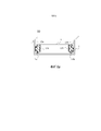
На фиг. 4a и фиг. 4b показаны решения по установке направляющих в устройство в соответствии с изобретением,In FIG. 4a and FIG. 4b shows installation solutions guides into the device in accordance with the invention,
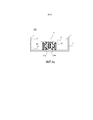
На фиг. 5 показано устройство в соответствии с изобретением, имеющее корпус и внутренние стенки квадратной формы,In FIG. 5 shows a device in accordance with the invention having a housing and square inner walls,
На фиг. 6a и фиг. 6b показаны решения по установке направляющего механизма в устройство в соответствии с изобретением,In FIG. 6a and FIG. 6b shows solutions for installing a guide mechanism in a device in accordance with the invention,
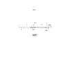
На фиг. 7 показаны направляющие на шариках, используемые в устройстве в соответствии с изобретением.In FIG. 7 shows the ball guides used in the device in accordance with the invention.
ПОДРОБНОЕ ОПИСАНИЕ ВАРИАНТОВ ОСУЩЕСТВЛЕНИЯDETAILED DESCRIPTION OF EMBODIMENTS
На фиг. 1a, 1b, 2a, 2b показаны различные виды устройства для приготовления пищи в соответствии с изобретением. Это устройство содержит корпус 1, имеющий внутренние стенки 2. Корпус выполнен, например, из литьевого пластикового материала. Устройство также содержит выдвижной элемент 3, расположенный внутри корпуса 1. Предпочтительно, ручка H прикреплена к выдвижному элементу 3, для того чтобы пользователь мог легко выдвигать и вдвигать выдвижной элемент. Выдвижной элемент 3 содержит варочную чашу 4 и корзину 5 для пищи. Корзина 5 для пищи располагается внутри варочной чаши 4. Устройство также содержит систему 6 для нагревания воздуха и воздушный вентилятор 7, расположенные внутри корпуса 1. Система 6 для нагревания воздуха и воздушный вентилятор 7 расположены, например, в верхней части внутри корпуса и предназначены для создания потока горячего воздуха внутри устройства. Устройство также содержит направляющий механизм 8, расположенный между внутренними стенками 2 и выдвижным элементом 3.In FIG. 1a, 1b, 2a, 2b show various kinds of cooking apparatus in accordance with the invention. This device comprises a
В частности, на фиг. 1b показано устройство в соответствии с изобретением после задвигания выдвижного элемента 3 внутрь устройства. Очевидно, что направляющий механизм 8 помогает размещению выдвижного элемента 3 внутри корпуса 1, приводя к тому, что область герметизации SA между выдвижным элементом и корпусом сводится к минимуму.In particular, in FIG. 1b shows a device in accordance with the invention after the sliding
В выдвижном элементе 3 преимущественно предусмотрена нижняя часть 9, которая используется для поддержки варочной чаши 4. Система 6 для нагревания преимущественно содержит резистор, на который подается электрическое напряжение. Поток горячего воздуха, показанный стрелками на фиг. 2a и фиг. 2b, направляется вниз между стенками варочной чаши 4 и стенками корзины 5 для пищи, и затем направляется вверх через воздухопроницаемую нижнюю часть корзины 5 для пищи. Воздухопроницаемая нижняя часть корзины 5 для пищи выполнена, например, из металлической проволоки, образующей сетку N. Альтернативно (не показано), поток горячего воздуха или его часть направляется вниз прямо в корзину 5 для пищи. Горячий воздух, который циркулирует в корзине 5 для пищи, предназначен для нагревания, варки или жарения пищевых ингредиентов, которые помещены пользователем в корзину 5 для пищи. Дополнительно, если система 6 для нагревания расположена в верхней части над корзиной 5 для пищи, пищевые ингредиенты, которые расположены в корзине 5 для пищи, также нагреваются, варятся или жарятся посредством радиации, производимой системой 6 для нагревания.Preferably, a
Преимущественно, устройство содержит панель управления CP, расположенную, например, на передней панели устройства. Панель управления используется для отображения различных параметров устройства на области E, то есть параметров, которые могут быть заданы пользователем посредством кнопок A, B, C, D, F:Advantageously, the device comprises a CP control panel located, for example, on the front panel of the device. The control panel is used to display various device parameters in area E, that is, parameters that can be set by the user using buttons A, B, C, D, F:
A: включение/выключение устройстваA: turn on / off the device
B: запуск/остановка системы 6 для нагревания воздуха и воздушного вентилятораB: start /
C: задание температуры и таймер для заданных значенийC: temperature setpoint and timer for setpoints
D: увеличение/уменьшение температуры горячего воздуха внутри устройстваD: increase / decrease hot air temperature inside the device
F: увеличение/уменьшениеe времени циркуляции горячего воздухаF: increase / decrease e hot air circulation time
На фиг. 3a, фиг. 3b, фиг. 3c, фиг. 3d показаны различные виды устройства в соответствии с изобретением при его эксплуатации пользователем.In FIG. 3a, FIG. 3b, FIG. 3c, FIG. 3d shows various types of devices in accordance with the invention during its operation by the user.
На фиг. 3a показан выдвижной элемент 3, выдвигаемый пользователем вдоль направления A1. Выдвижение выдвижного элемента вдоль направления A1 предназначено для доступа к корзине 5 для пищи, либо для загрузки корзины 5 для пищи пищевыми ингредиентами, либо для выгрузки пищевых ингредиентов, которые уже приготовлены. Направляющий механизм 8 способствует манипуляциям с выдвижным элементом 3.In FIG. 3a, a
На фиг. 3b показан выдвижной элемент 3 после того, как он был выдвинут пользователем вдоль направления A1. В этом положении пользователь может непосредственно вынимать уже приготовленные пищевые ингредиенты из корзины 5 для пищи.In FIG. 3b, the
На фиг.3c показан выдвижной элемент 3 после того, как он был выдвинут пользователем вдоль направления А1. В этом положении пользователь может вынуть корзину для пищи из варочной чаши 4 вдоль направлении A2, затем поместить уже готовые пищевые ингредиенты на отдельную тарелку, как показано на фиг. 3d.Fig. 3c shows a
В предпочтительном варианте осуществления, как показано на фиг. 1a, направляющий механизм 8 расположен между нижней частью 2a внутренних стенок 2 и нижней частью 9 выдвижного элемента 3.In a preferred embodiment, as shown in FIG. 1a, a
В предпочтительном варианте осуществления, как показано на фиг. 1a, направляющий механизм 8 расположен вдоль продольной оси симметрии A3 нижней части 2a внутренних стенок 2. Продольная ось симметрии A3 соответствует центральной оси нижней части 2a внутренних стенок 2.In a preferred embodiment, as shown in FIG. 1a, the
В предпочтительном варианте осуществления, как показано на увеличенном виде на фиг. 1c, направляющий механизм 8 содержит первую направляющую 10а и вторую направляющую 10b, расположенные параллельно друг другу.In a preferred embodiment, as shown in an enlarged view of FIG. 1c, the
Первая направляющая 10а и вторая направляющая 10b преимущественно соответствуют такому типу направляющей, который описан со ссылкой на фиг. 7.The
На фиг. 7 показан такой тип направляющей, который может быть использован в соответствии с изобретением. Направляющая содержит наружную часть E, имеющую длину L1, и внутреннюю часть I, имеющую длину L2. Наружная часть E содержит область, имеющую два противоположных линейных ряда BB1 и BB2, содержащих металлические шарики и образующие связь посредством шариков с внутренней частью I. Наружная часть E и внутренняя часть I могут скользить линейно относительно друг друга. Как вариант, направляющая является направляющей на роликах, в которой вместо металлических шариков используются металлические ролики. Следует отметить, что вместо использования двухкомпонентных направляющих, как показано на фиг. 7, могут быть также использованы трехкомпонентные направляющие, для того чтобы увеличивать амплитуду линейного перемещения выдвижного элемента при выдвижении из корпуса.In FIG. 7 shows a type of rail that can be used in accordance with the invention. The guide comprises an outer part E having a length L1 and an inner part I having a length L2. The outer part E contains a region having two opposite linear rows BB1 and BB2 containing metal balls and forming a connection by means of balls with the inner part I. The outer part E and the inner part I can slide linearly relative to each other. Alternatively, the guide is a roller guide in which metal rollers are used instead of metal balls. It should be noted that instead of using two-component guides, as shown in FIG. 7, ternary guides can also be used in order to increase the linear amplitude of the sliding element when extended from the housing.
На фиг. 4a показано решение по установке первой направляющей 10а и второй направляющей 10b в устройство в соответствии с изобретением. Предпочтительно, могут быть использованы направляющие, описанные со ссылкой на фиг. 7. Внутренняя часть первой направляющей 10а соединена с первой линейной опорой S1, которая прикреплена к нижней части 2a внутренних стенок 2. Внутренняя часть второй направляющей 10b соединена со второй линейной опорой S2, которая прикреплена к нижней части 2a внутренних стенок 2. Наружная часть первой направляющей 10а и наружная часть второй направляющей 10b прикреплена к выдвижному элементу 3 через нижнюю часть 9. Предпочтительно, как показано, нижняя часть 9 выдвижного элемента 3 образует U-образную форму вдоль своей центральной части.In FIG. 4a shows a solution for installing a
На фиг. 4b показано решение по установке первой направляющей 10а и второй направляющей 10b в устройство в соответствии с изобретением. Предпочтительно, могут быть использованы направляющие, описанные со ссылкой на фиг. 7. Внутренняя часть первой направляющей 10а соединена с первой линейной ножкой L1, проходящей вниз и прикрепленной к нижней части 9 выдвижного элемента 3. Внутренняя часть второй направляющей 10b соединена со второй линейной ножкой L2, проходящей вниз и прикрепленной к нижней части 9 выдвижного элемента 3. Наружная часть первой направляющей 10а и наружная часть второй направляющей 10b прикреплены к нижней части 9 выдвижного элемента 3 посредством линейной опоры S3, и линейная опора S3 прикреплена к нижней части 2a внутренних стенок 2.In FIG. 4b shows a solution for installing a
На фиг. 5 показано устройство в соответствии с изобретением, в котором корпус 1 и внутренние стенки 2 имеют квадратные формы. В этом случае направляющий механизм 8 преимущественно устанавливается либо на боковые части внутренних стенок 2, либо на нижние части 2a внутренних стенок 2, как подробно показано на фиг. 6a и фиг. 6b.In FIG. 5 shows a device in accordance with the invention, in which the
На фиг. 6a показано решение по установке в устройство в соответствии с изобретением направляющего механизма 8, содержащего первую направляющую 11а и вторую направляющую 11b. Предпочтительно, могут быть использованы направляющие, описанные со ссылкой на фиг. 7. Первая направляющая 11а расположена между первой боковой частью 12a внутренних стенок 2 и выдвижным элементом 3. Внутренняя часть первой направляющей 11а соединена с первой боковой частью 12a, и наружная часть первой направляющей 11а соединена с ножкой 13a, проходящей вниз от нижней части 9 выдвижного элемента 3. Вторая направляющая 11b расположена между второй боковой частью 12b внутренних стенок 2 и выдвижным элементом 3. Внутренняя часть второй направляющей 11b соединена со второй боковой частью 12b, и наружная часть второй направляющей 11b соединена с ножкой 13b, проходящей вниз от нижней части 9 выдвижного элемента 3.In FIG. 6a shows a solution for installing in the device in accordance with the invention a
На фиг. 6b показано решение, альтернативное решению из фиг. 6a, в котором первая направляющая 11a и вторая направляющая 11b повернуты на угол 90° вокруг своих продольных осей по сравнению со способом установки из фиг. 6a. В результате внутренние части направляющих 11a и 11b прикрепляют к нижней части 2a внутренних стенок 2, и наружные части направляющих 11a и 11b прикрепляют к нижней части выдвижного элемента 3.In FIG. 6b shows a solution alternative to the solution of FIG. 6a, in which the first guide 11a and the
Другие изменения к раскрытым вариантам осуществления могут быть понятны и могут быть выполнены специалистами в данной области техники, осуществляющими изобретение, на основе изучения чертежей, описания и прилагаемой формулы изобретения. В формуле изобретения слово «содержащий» не исключает других элементов или этапов, и неопределенные артикли "a" или "an" не исключают наличия множества элементов. Один узел может выполнять функции нескольких элементов, описанных в формуле изобретения. Тот факт, что определенные меры упоминаются в различных зависимых пунктах формулы изобретения, не означает, что комбинация этих мер не может быть использована для преимущества. Любые ссылочные позиции в формуле изобретения не являются позициями, ограничивающими объем формулы изобретения.Other changes to the disclosed embodiments may be understood and may be made by those skilled in the art practicing the invention based on an examination of the drawings, description, and appended claims. In the claims, the word “comprising” does not exclude other elements or steps, and the indefinite articles “a” or “an” do not exclude the presence of a plurality of elements. One node can perform the functions of several elements described in the claims. The fact that certain measures are mentioned in the various dependent claims does not mean that a combination of these measures cannot be used to advantage. Any reference positions in the claims are not positions limiting the scope of the claims.
Claims (12)
Applications Claiming Priority (3)
| Application Number | Priority Date | Filing Date | Title |
|---|---|---|---|
| CN201310374660.1A CN104414427A (en) | 2013-08-26 | 2013-08-26 | Drawer device with sliding mechanism for preparing food |
| CN201310374660.1 | 2013-08-26 | ||
| PCT/IB2014/063906 WO2015028911A1 (en) | 2013-08-26 | 2014-08-14 | Apparatus for preparing food having a drawer with a sliding mechanism |
Publications (3)
| Publication Number | Publication Date |
|---|---|
| RU2016111110A RU2016111110A (en) | 2017-10-03 |
| RU2016111110A3 RU2016111110A3 (en) | 2018-05-25 |
| RU2662684C2 true RU2662684C2 (en) | 2018-07-26 |
Family
ID=51494326
Family Applications (1)
| Application Number | Title | Priority Date | Filing Date |
|---|---|---|---|
| RU2016111110A RU2662684C2 (en) | 2013-08-26 | 2014-08-14 | Food preparation device with drawer and sliding mechanism |
Country Status (9)
| Country | Link |
|---|---|
| US (1) | US10448786B2 (en) |
| EP (1) | EP3038503B1 (en) |
| JP (1) | JP6475731B2 (en) |
| KR (1) | KR20160048890A (en) |
| CN (3) | CN104414427A (en) |
| AU (1) | AU2014313885B2 (en) |
| BR (1) | BR112016003855B1 (en) |
| RU (1) | RU2662684C2 (en) |
| WO (1) | WO2015028911A1 (en) |
Cited By (1)
| Publication number | Priority date | Publication date | Assignee | Title |
|---|---|---|---|---|
| RU199881U1 (en) * | 2020-03-03 | 2020-09-24 | Фарит Сулейманович Юнусов | COOKER |
Families Citing this family (26)
| Publication number | Priority date | Publication date | Assignee | Title |
|---|---|---|---|---|
| WO2017215988A1 (en) * | 2016-06-15 | 2017-12-21 | Koninklijke Philips N.V. | Air-frying cooker |
| FR3064168B1 (en) * | 2017-03-22 | 2019-03-22 | Seb S.A. | COOKING APPARATUS WITH ARTICULATED-ARM MECHANISM |
| DE202017101922U1 (en) * | 2017-03-31 | 2017-05-26 | Reamotion Gmbh | Device for heating and / or cooking food |
| US11278151B2 (en) | 2017-08-09 | 2022-03-22 | Sharkninja Operating Llc | Cooking device and components thereof |
| CN108209536A (en) * | 2018-02-08 | 2018-06-29 | 深圳市饭立得科技有限公司 | A kind of stove |
| USD914447S1 (en) | 2018-06-19 | 2021-03-30 | Sharkninja Operating Llc | Air diffuser |
| USD883014S1 (en) | 2018-08-09 | 2020-05-05 | Sharkninja Operating Llc | Food preparation device |
| USD903413S1 (en) | 2018-08-09 | 2020-12-01 | Sharkninja Operating Llc | Cooking basket |
| USD882329S1 (en) * | 2018-08-09 | 2020-04-28 | Sharkninja Operating Llc | Food preparation device |
| USD883015S1 (en) | 2018-08-09 | 2020-05-05 | Sharkninja Operating Llc | Food preparation device and parts thereof |
| USD934027S1 (en) | 2018-08-09 | 2021-10-26 | Sharkninja Operating Llc | Reversible cooking rack |
| USD883729S1 (en) * | 2018-10-25 | 2020-05-12 | Etekcity Corporation | Air fryer |
| CA188439S (en) * | 2019-02-01 | 2020-11-18 | Seb Soc Par Actions Simplifiee | ELECTRIC FRYER |
| US11051654B2 (en) | 2019-02-25 | 2021-07-06 | Sharkninja Operating Llc | Cooking device and components thereof |
| CN212788226U (en) | 2019-02-25 | 2021-03-26 | 沙克忍者运营有限责任公司 | Cooking system |
| US10575679B1 (en) * | 2019-05-28 | 2020-03-03 | Team International Group of America Inc. | Air or deep fryer |
| USD982375S1 (en) | 2019-06-06 | 2023-04-04 | Sharkninja Operating Llc | Food preparation device |
| USD918654S1 (en) | 2019-06-06 | 2021-05-11 | Sharkninja Operating Llc | Grill plate |
| WO2021011642A1 (en) | 2019-07-15 | 2021-01-21 | Sharkninja Operating Llc | Cooking device and components thereof |
| US11647861B2 (en) | 2020-03-30 | 2023-05-16 | Sharkninja Operating Llc | Cooking device and components thereof |
| USD938219S1 (en) * | 2020-04-03 | 2021-12-14 | Midea Group Co., Ltd. | Air fryer |
| USD943336S1 (en) * | 2020-05-18 | 2022-02-15 | Midea Group Co., Ltd | Air fryer |
| USD968156S1 (en) * | 2020-09-23 | 2022-11-01 | Ningbo Careline Electric Appliance Co., Ltd. | Steam air fryer |
| CN114468786A (en) * | 2020-10-23 | 2022-05-13 | 斯迪道恩集团有限公司 | Smokeless barbecue grill and air fryer |
| US11882961B1 (en) | 2023-01-18 | 2024-01-30 | Sharkninja Operating Llc | Cover plate for cooking devices |
| USD984196S1 (en) * | 2023-02-08 | 2023-04-25 | Suzhou Wanjiade Technology Co., Ltd. | Air fryer liner |
Citations (4)
| Publication number | Priority date | Publication date | Assignee | Title |
|---|---|---|---|---|
| FR1220280A (en) * | 1958-02-18 | 1960-05-24 | Grill | |
| US3301169A (en) * | 1965-02-19 | 1967-01-31 | George A Young | Table oven |
| US6789861B1 (en) * | 1999-10-25 | 2004-09-14 | Accuride International Gmbh | Support system for cooking items in a baking oven |
| EP2613679A1 (en) * | 2010-09-10 | 2013-07-17 | Koninklijke Philips Electronics N.V. | Apparatus for preparing food |
Family Cites Families (24)
| Publication number | Priority date | Publication date | Assignee | Title |
|---|---|---|---|---|
| US1095363A (en) * | 1909-05-27 | 1914-05-05 | Yawman & Erbe Mfg Co | Furniture-drawer. |
| US1694762A (en) * | 1927-04-19 | 1928-12-11 | John A Susbauer | Electric cooker |
| US4441773A (en) * | 1982-02-08 | 1984-04-10 | Hardware Designers, Inc. | Bottom mounted drawer slide assembly |
| DE4023949A1 (en) | 1990-02-21 | 1991-08-22 | Bosch Siemens Hausgeraete | OVEN |
| CN2253941Y (en) * | 1996-01-30 | 1997-05-14 | 庄俊夫 | Double space synchronous cooking electric pot |
| DE19730829A1 (en) * | 1997-07-18 | 1999-01-28 | Riesselmann Gottfried | Device for heating food |
| JP4594597B2 (en) * | 2003-02-28 | 2010-12-08 | 大阪瓦斯株式会社 | grill |
| JP2004353960A (en) * | 2003-05-29 | 2004-12-16 | Matsushita Electric Ind Co Ltd | Gas cooker |
| US20050133502A1 (en) | 2003-12-18 | 2005-06-23 | Daewoo Electronics Corporation | Door structure of microwave oven usable as pizza oven |
| EP1867264A1 (en) * | 2006-06-16 | 2007-12-19 | Kavaring Cooking Systems B.V. i.o. | Apparatus for preparing food |
| KR20090010615A (en) * | 2007-07-24 | 2009-01-30 | 에이치 앤드 오아시스 인터내셔날 주식회사 | Functional heating device for cooking |
| TR200706719A2 (en) | 2007-09-28 | 2009-04-21 | Vestel Beyaz E�Ya Sanay� Ve T�Caret A.�. | Telescopic rail system. |
| CN101218979B (en) * | 2008-01-29 | 2011-05-25 | 郑州市嵩山绿源畜牧养殖有限公司 | High-efficiency energy-saving environment-protection barbecue machine |
| MX2010008926A (en) * | 2008-02-15 | 2011-02-23 | Rigel Pharmaceuticals Inc | Pyrimidine-2-amine compounds and their use as inhibitors of jak kinases. |
| JP5248198B2 (en) * | 2008-05-23 | 2013-07-31 | 株式会社東芝 | Cooker |
| US8291816B2 (en) * | 2008-06-04 | 2012-10-23 | Sharp Kabushiki Kaisha | Drawer type cooking device |
| JP2010112586A (en) * | 2008-11-04 | 2010-05-20 | Mitsubishi Electric Corp | Heating cooker |
| JP2010133676A (en) * | 2008-12-08 | 2010-06-17 | Sharp Corp | Drawer type cooking device |
| CN102429570A (en) * | 2011-11-01 | 2012-05-02 | 何锦涛 | Full-automatic numerical-control porridge and soup stewing machine |
| JP2013142497A (en) | 2012-01-11 | 2013-07-22 | Hitachi Appliances Inc | Heating cooker |
| CN202891672U (en) * | 2012-10-11 | 2013-04-24 | 虞世高 | Frying pan by using air circulation speeding up to fry food |
| CN203041949U (en) * | 2013-01-29 | 2013-07-10 | 浙江安德电器有限公司 | Pull door device |
| BE1022220B1 (en) * | 2013-03-26 | 2016-03-02 | Cook'n Fit | FRIED OVEN |
| CN203841555U (en) * | 2013-08-26 | 2014-09-24 | 皇家飞利浦有限公司 | Drawer device used for food preparation and provided with sliding mechanism |
-
2013
- 2013-08-26 CN CN201310374660.1A patent/CN104414427A/en active Pending
- 2013-08-26 CN CN202010237439.1A patent/CN111493682A/en active Pending
-
2014
- 2014-08-14 WO PCT/IB2014/063906 patent/WO2015028911A1/en active Application Filing
- 2014-08-14 US US14/912,663 patent/US10448786B2/en active Active
- 2014-08-14 CN CN201480046971.8A patent/CN105491923A/en active Pending
- 2014-08-14 JP JP2016537406A patent/JP6475731B2/en not_active Expired - Fee Related
- 2014-08-14 AU AU2014313885A patent/AU2014313885B2/en active Active
- 2014-08-14 EP EP14761701.3A patent/EP3038503B1/en active Active
- 2014-08-14 BR BR112016003855-0A patent/BR112016003855B1/en active IP Right Grant
- 2014-08-14 RU RU2016111110A patent/RU2662684C2/en active
- 2014-08-14 KR KR1020167007968A patent/KR20160048890A/en not_active Application Discontinuation
Patent Citations (4)
| Publication number | Priority date | Publication date | Assignee | Title |
|---|---|---|---|---|
| FR1220280A (en) * | 1958-02-18 | 1960-05-24 | Grill | |
| US3301169A (en) * | 1965-02-19 | 1967-01-31 | George A Young | Table oven |
| US6789861B1 (en) * | 1999-10-25 | 2004-09-14 | Accuride International Gmbh | Support system for cooking items in a baking oven |
| EP2613679A1 (en) * | 2010-09-10 | 2013-07-17 | Koninklijke Philips Electronics N.V. | Apparatus for preparing food |
Cited By (1)
| Publication number | Priority date | Publication date | Assignee | Title |
|---|---|---|---|---|
| RU199881U1 (en) * | 2020-03-03 | 2020-09-24 | Фарит Сулейманович Юнусов | COOKER |
Also Published As
| Publication number | Publication date |
|---|---|
| US20160192808A1 (en) | 2016-07-07 |
| CN104414427A (en) | 2015-03-18 |
| EP3038503A1 (en) | 2016-07-06 |
| EP3038503B1 (en) | 2020-12-02 |
| AU2014313885B2 (en) | 2019-01-24 |
| JP2016529468A (en) | 2016-09-23 |
| BR112016003855A2 (en) | 2017-08-01 |
| JP6475731B2 (en) | 2019-02-27 |
| BR112016003855B1 (en) | 2022-03-22 |
| CN105491923A (en) | 2016-04-13 |
| KR20160048890A (en) | 2016-05-04 |
| AU2014313885A1 (en) | 2016-04-21 |
| CN111493682A (en) | 2020-08-07 |
| RU2016111110A3 (en) | 2018-05-25 |
| US10448786B2 (en) | 2019-10-22 |
| RU2016111110A (en) | 2017-10-03 |
| WO2015028911A1 (en) | 2015-03-05 |
Similar Documents
| Publication | Publication Date | Title |
|---|---|---|
| RU2662684C2 (en) | Food preparation device with drawer and sliding mechanism | |
| KR102549150B1 (en) | Cooking appliance and control method for the same | |
| JP6688532B2 (en) | Vertical grill with external drip tray module | |
| CN106618251B (en) | Rotisserie oven with jet pipe cleaning system | |
| US20130118471A1 (en) | Extendable rack mounting system for an oven appliance | |
| US10006639B2 (en) | Appliance side panel with air channel | |
| CN211559785U (en) | Food processor with steam function | |
| CN203841555U (en) | Drawer device used for food preparation and provided with sliding mechanism | |
| KR20210129102A (en) | Storable Countertop Cooking System | |
| US8826898B2 (en) | Metal rack for an oven appliance | |
| US20160195281A1 (en) | Oven rack storage | |
| US20150101590A1 (en) | Spring loaded shelf for an oven appliance | |
| KR20200025508A (en) | Electric roaster | |
| JP2010142437A (en) | Kitchen furniture | |
| US2156993A (en) | Vapor bath cabinet | |
| CN113974447A (en) | Countertop cooking system | |
| JP2016169940A (en) | Heating cooker | |
| US20160025355A1 (en) | Oven appliance and method for operating oven appliance | |
| CN113116176A (en) | Food processor with steam function | |
| JP2015072094A (en) | Heating cooker | |
| US20230135267A1 (en) | Mesh screen to prevent access to hot surfaces within an oven appliance | |
| JP4644030B2 (en) | Cooker | |
| JP6211201B2 (en) | Water purifier with circulation sterilization system | |
| ES2413097A1 (en) | Oven for food cooking. (Machine-translation by Google Translate, not legally binding) | |
| KR102500682B1 (en) | Laundry treating apparatus |