EP3038503B1 - Apparatus for preparing food having a drawer with a sliding mechanism - Google Patents
Apparatus for preparing food having a drawer with a sliding mechanism Download PDFInfo
- Publication number
- EP3038503B1 EP3038503B1 EP14761701.3A EP14761701A EP3038503B1 EP 3038503 B1 EP3038503 B1 EP 3038503B1 EP 14761701 A EP14761701 A EP 14761701A EP 3038503 B1 EP3038503 B1 EP 3038503B1
- Authority
- EP
- European Patent Office
- Prior art keywords
- drawer
- slider
- sliding mechanism
- food
- bottom part
- Prior art date
- Legal status (The legal status is an assumption and is not a legal conclusion. Google has not performed a legal analysis and makes no representation as to the accuracy of the status listed.)
- Active
Links
- 230000007246 mechanism Effects 0.000 title claims description 32
- 238000010438 heat treatment Methods 0.000 claims description 11
- 235000012041 food component Nutrition 0.000 description 16
- 239000005417 food ingredient Substances 0.000 description 16
- 238000010411 cooking Methods 0.000 description 3
- 230000001419 dependent effect Effects 0.000 description 2
- 230000000694 effects Effects 0.000 description 2
- 238000007789 sealing Methods 0.000 description 2
- 238000004140 cleaning Methods 0.000 description 1
- 239000013256 coordination polymer Substances 0.000 description 1
- 239000004615 ingredient Substances 0.000 description 1
- 239000000463 material Substances 0.000 description 1
- 239000002991 molded plastic Substances 0.000 description 1
- 230000005855 radiation Effects 0.000 description 1
- 230000006641 stabilisation Effects 0.000 description 1
- 238000011105 stabilization Methods 0.000 description 1
Images


Classifications
-
- A—HUMAN NECESSITIES
- A47—FURNITURE; DOMESTIC ARTICLES OR APPLIANCES; COFFEE MILLS; SPICE MILLS; SUCTION CLEANERS IN GENERAL
- A47J—KITCHEN EQUIPMENT; COFFEE MILLS; SPICE MILLS; APPARATUS FOR MAKING BEVERAGES
- A47J37/00—Baking; Roasting; Grilling; Frying
- A47J37/04—Roasting apparatus with movably-mounted food supports or with movable heating implements; Spits
- A47J37/049—Details of the food supports not specially adapted to one of the preceding types of food supports
-
- A—HUMAN NECESSITIES
- A47—FURNITURE; DOMESTIC ARTICLES OR APPLIANCES; COFFEE MILLS; SPICE MILLS; SUCTION CLEANERS IN GENERAL
- A47J—KITCHEN EQUIPMENT; COFFEE MILLS; SPICE MILLS; APPARATUS FOR MAKING BEVERAGES
- A47J37/00—Baking; Roasting; Grilling; Frying
- A47J37/06—Roasters; Grills; Sandwich grills
- A47J37/0623—Small-size cooking ovens, i.e. defining an at least partially closed cooking cavity
- A47J37/0629—Small-size cooking ovens, i.e. defining an at least partially closed cooking cavity with electric heating elements
- A47J37/0641—Small-size cooking ovens, i.e. defining an at least partially closed cooking cavity with electric heating elements with forced air circulation, e.g. air fryers
Definitions
- the present invention relates to an apparatus for preparing food, in particular by moving a flow of hot air over food ingredients.
- An apparatus for preparing food is known from for instance EP2613679 and EP2034872B1 .
- Such type of apparatus is used in a domestic environment and provides a solution for heating, cooking, and/or frying food ingredients by circulating a flow of hot air around those food ingredients.
- Such an apparatus generally comprises an enclosed drawer having a food basket into which food ingredients are placed by user. The drawer can be taken out from the apparatus by user, for example, via a handle fixed to the drawer, so that user can access the inside part of the food basket and put the food ingredients in it. After the drawer loaded with food ingredients is put back inside the apparatus, a flow of hot air is then circulated around the food ingredients in order to heat, cook, and/or fry ingredients.
- a further apparatus for preparing food is known for instance from CN202891672U .
- an apparatus comprising:
- the sliding mechanism allows to correctly position the drawer inside the apparatus.
- the sealing area between the drawer and the shell is thus minimized, which avoids the leak of hot air circulating inside the apparatus.
- the heating/cooking/frying efficiency of food ingredients is optimized.
- the weight to be manipulated is reduced by the fact that the food basket can be taken out without having to take out the pan at the same time. While the pan still can be taken out easily for cleaning without having to disassemble parts.
- the sliding mechanism is placed between the bottom part of the internal walls, and the bottom part of the drawer.
- This particular position of the sliding mechanism guaranties an easy and compact mounting of the sliding mechanism inside the apparatus.
- the sliding mechanism is positioned along the longitudinal symmetry axis of the bottom part of the internal walls.
- the sliding mechanism comprises a first slider and a second slider positioned parallel to each other.
- This feature allows a better stabilization of the drawer when the drawer is pulled-out by the user.
- This sliding mechanism allows an easy assembly when the shell and its internal walls are square-shaped, and improves the stability of the drawer when the drawer is pulled-out by the user.
- the first slider and the second slider are ball-bearing sliders.
- This sliding mechanism allows a smooth sliding movement of the drawer, even if the weight of the food basket is significant. Moreover, this reduces the wearing effect of the sliding mechanism along the time.
- the first slider and the second slider are roller-mounted sliders.
- This sliding mechanism allows a cost-effective solution for a smooth sliding movement of the drawer, even if the weight of the food basket is significant. Moreover, this reduces the wearing effect of the sliding mechanism along the time.
- the first slider and the second slider are two-parts sliders.
- This type of sliding mechanism is advantageous because it is a cost-effective solution.
- the first slider and the second slider are three-parts sliders.
- This type of sliding mechanism is advantageous because it allows the drawer to extend beyond the shell walls, and thus to facilitate the access to the pan and food basket by user.
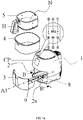
- Fig.1a , Fig.1b , Fig.2a , Fig.2b describe various views of an apparatus for preparing food according to the invention.
- This apparatus comprises a shell 1 having internal walls 2.
- the shell is made of molded-plastic material.
- the apparatus also comprises a drawer 3 placed inside the shell 1.
- a handle H is provided attached to the drawer 3 so that user can easily pull-out and pull-in and the drawer.
- the drawer 3 comprises a pan 4 and a food basket 5.
- the food basket 5 is placed inside the pan 4.
- the apparatus also comprises an air heating system 6 and an air fan 7 placed inside the shell 1.
- the air heating system 6 and the air fan 7 are placed in the upper part inside the shell, and are intended to generate a flow of hot air inside the apparatus.
- the apparatus also comprises a sliding mechanism 8 placed between the internal walls 2 and the drawer 3.
- FIG.1b illustrates the apparatus according to the invention after the drawer 3 has been pulled inside the apparatus. This is apparent that the sliding mechanism 8 helps positioning the drawer 3 inside the shell 1, resulting in that the sealing area SA between the drawer and the shell is minimized.
- the drawer 3 is advantageously provided with a bottom part 9 that is used to support the pan 4.
- the heating system 6 advantageously comprises a resistor supplied by electrical voltage.
- the flow of hot air illustrated by arrows in Fig.2a and Fig.2b , is guided downwards between walls of the pan 4 and walls of the food basket 5, then guided upwards through the air-permeable bottom part of the food basket 5.
- the permeable bottom part of the food basket 5 is made, for example, of metallic wires forming a net N.
- the flow of hot air, or a portion of it is guided downwards directly in the food basket 5.
- the hot air which is circulated in the food basket 5 is intended to heat, cook or fry food ingredients that are placed by user in the food basket 5. Additionally, if the heating system 6 is positioned in the upper part above the food basket 5, food ingredients that are placed in the food basket 5 are also heated, cooked or fried via radiation produced by the heating system 6.
- the apparatus comprises a control panel CP, for example placed on the front part of the apparatus.
- the control panel is used to display various parameters of the apparatus on area E, parameters that can be set by user via buttons A, B, C, D, F:
- Fig.3a , Fig.3b , Fig.3c , Fig.3d illustrate various views of an apparatus according to the invention when used by a user.
- Fig.3a illustrates the drawer 3 being pulled-out by user along direction A1. Pulling-out drawer along direction A1 is intended to access the food basket 5, for either loading the food basket 5 with food ingredients, or unloading food ingredients which are already prepared.
- the sliding mechanism 8 facilitates the manipulation of the drawer 3.
- Fig.3b illustrates the drawer 3 after having been pulled-out by user along direction A1. In this position, user can directly take away the already prepared food ingredients from the food basket.
- Fig.3c illustrates the drawer 3 after having been pulled-out by user along direction A1. In this position, user can pull-out the food basket 5 from the pan 4 along direction A2, then pour the food ingredients already prepared in a separate plate, as illustrated in Fig.3d .
- the sliding mechanism 8 is placed between the bottom part 2a of the internal walls 2, and the bottom part 9 of the drawer 3.
- the sliding mechanism 8 is positioned along the longitudinal symmetry axis A3 of the bottom part 2a of the internal walls 2.
- the longitudinal symmetry axis A3 corresponds to the central axis of the bottom part 2a of the internal walls 2.
- the sliding mechanism 8 comprises a first slider 10a and a second slider 10b positioned parallel to each other.
- the first slider 10a and the second slider 10b advantageously correspond to a type of slider as described along with Fig.7 .
- Fig.7 illustrates a type of slider that can be used in an apparatus according to the invention.
- the slider comprises an external part E having a length L1 and an internal part I having a length L2.
- the external part E comprises an area having two opposite linear rows BB1 and BB2 comprising metallic balls and forming linear ball-bearing liaison with the internal part I.
- the external part E and the internal part I can slide linearly compared to each other.
- the slider is roller-mounted slider, where metallic rollers are used instead of metallic balls.
- three parts sliders could also be used, in order to increase the amplitude of linear movement of the drawer when being pulled-out from the shell.
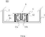
- Fig.4a illustrates a solution to mount the first slider 10a and the second slider 10b into an apparatus according to the invention.
- sliders as described along with Fig.7 can be used.
- the internal part of the first slider 10a is connected to a first linear support S1 which is fixed to the bottom part 2a of the internal walls 2.
- the internal part of the second slider 10b is connected to a second linear support S2 which is fixed to the bottom part 2a of the internal walls 2.
- the external part of the first slider 10a and the external part of the second slider 10b are fixed to the drawer 3 via the bottom part 9.
- the bottom part 9 of the drawer 3 forms a U shape along its central part.
- Fig.4b illustrates a solution to mount the first slider 10a and the second slider 10b into an apparatus according to the invention.
- sliders as described along with Fig.7 can be used.
- the internal part of the first slider 10a is connected to a first linear leg L1 extending downwards and fixed to the bottom part 9 of drawer 3.
- the internal part of the second slider 10b is connected to a second linear leg L2 extending downwards and fixed to the bottom part 9 of drawer 3.
- the external part of the first slider 10a and the external part of the second slider 10b are fixed to the bottom part 9 of the drawer 3 by the linear support S3, and the linear support S3 is fixed to the bottom part 2a of the internal walls 2.
- Fig.5 illustrates an apparatus where the shell 1 and internal walls 2 are squared-shape.
- the sliding mechanism 8 is advantageously mounted either on the lateral parts of the internal walls 2, according to a solution that does not fall under the scope of the claims, or, according to the invention, on the bottom part 2a of the internal walls 2, as further detailed in Fig.6a and Fig.6b .
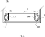
- Fig.6a illustrates a solution to mount into an apparatus, a sliding mechanism 8 comprising a first slider 11a and a second slider 11b.
- This solution does nt fall under the scope of the claims.
- sliders as described along with Fig.7 can be used.
- the first slider 11a is placed between a first lateral part 12a of the internal walls 2 and the drawer 3.
- the internal part of the first slider 11a is connected to the first lateral part 12a, and the external part of the first slider 11a is connected to a leg 13a extending downwards from the bottom part 9 of drawer 3.
- the second slider 11b is placed between a second lateral part 12b of the internal walls 2 and the drawer 3.
- the internal part of the second slider 11b is connected to the second lateral part 12b, and the external part of the second slider 11b is connected to a leg 13b extending downwards from the bottom part 9 of drawer 3.
- Fig.6b illustrates an alternative solution of Fig.6a , where the first slider 11a and the second slider 11b are rotated by an angle of 90° around their longitudinal axis compared to the mounting of Fig.6a .
- the internal parts of sliders 11a and 11b are fixed to the bottom part 2a of the internal walls 2, and the external parts of sliders 11a and 11b are fixed to bottom part 9 of drawer 3.
Landscapes
- Engineering & Computer Science (AREA)
- Food Science & Technology (AREA)
- Drawers Of Furniture (AREA)
- Cookers (AREA)
- Baking, Grill, Roasting (AREA)
Description
- The present invention relates to an apparatus for preparing food, in particular by moving a flow of hot air over food ingredients.
- An apparatus for preparing food is known from for instance
EP2613679 andEP2034872B1 . Such type of apparatus is used in a domestic environment and provides a solution for heating, cooking, and/or frying food ingredients by circulating a flow of hot air around those food ingredients. Such an apparatus generally comprises an enclosed drawer having a food basket into which food ingredients are placed by user. The drawer can be taken out from the apparatus by user, for example, via a handle fixed to the drawer, so that user can access the inside part of the food basket and put the food ingredients in it. After the drawer loaded with food ingredients is put back inside the apparatus, a flow of hot air is then circulated around the food ingredients in order to heat, cook, and/or fry ingredients. - With such types of known apparatus, it is sometimes difficult to correctly position the drawer inside the apparatus. If the drawer is not correctly positioned, the hot air which is circulated inside the apparatus leaks outside the apparatus, resulting in a lower heating/cooking/frying efficiency. Moreover, if a substantive amount of food ingredients is put by user into the food basket, the weight of the drawer gets significant, resulting in inconveniences for user when manipulating the drawer.
- A further apparatus for preparing food is known for instance from
CN202891672U . - It is an object of the invention to propose an improved apparatus for preparing food. The invention is defined by the independent claims. The dependent claims define advantageous embodiments.
- According to the present invention, there is provided an apparatus comprising:
- a shell having internal walls,
- a drawer placed inside the shell, the drawer comprising a pan and a food basket, the food basket being placed inside the pan,
- an air heating system and an air fan placed inside the shell,
- a sliding mechanism placed between the internal walls and the drawer, wherein the sliding mechanism (8) is placed between the bottom part (2a) of the internal walls (2), and the bottom part (9) of the drawer (3).
- The sliding mechanism allows to correctly position the drawer inside the apparatus. The sealing area between the drawer and the shell is thus minimized, which avoids the leak of hot air circulating inside the apparatus. As a consequence, the heating/cooking/frying efficiency of food ingredients is optimized. Moreover, even if a substantive amount of food ingredients is put by user into the food basket, efforts to manipulate the drawer by user are highly reduced. Also, thanks to the assembly of the food basket inside the pan, the weight to be manipulated is reduced by the fact that the food basket can be taken out without having to take out the pan at the same time. While the pan still can be taken out easily for cleaning without having to disassemble parts.
- According to the invention, the sliding mechanism is placed between the bottom part of the internal walls, and the bottom part of the drawer.
- This particular position of the sliding mechanism guaranties an easy and compact mounting of the sliding mechanism inside the apparatus.
- In a preferred embodiment, the sliding mechanism is positioned along the longitudinal symmetry axis of the bottom part of the internal walls.
- When the shell and its internal walls are round-shaped, positioning the sliding mechanism along the longitudinal symmetry axis allows choosing sliding mechanisms having longer dimension, in order the drawer can be fully taken out from the shell.
- In a preferred embodiment, the sliding mechanism comprises a first slider and a second slider positioned parallel to each other.
- This feature allows a better stabilization of the drawer when the drawer is pulled-out by the user.
- This sliding mechanism allows an easy assembly when the shell and its internal walls are square-shaped, and improves the stability of the drawer when the drawer is pulled-out by the user.
- In a preferred embodiment, the first slider and the second slider are ball-bearing sliders.
- This sliding mechanism allows a smooth sliding movement of the drawer, even if the weight of the food basket is significant. Moreover, this reduces the wearing effect of the sliding mechanism along the time.
- In a preferred embodiment, the first slider and the second slider are roller-mounted sliders.
- This sliding mechanism allows a cost-effective solution for a smooth sliding movement of the drawer, even if the weight of the food basket is significant. Moreover, this reduces the wearing effect of the sliding mechanism along the time.
- In a preferred embodiment, the first slider and the second slider are two-parts sliders.
- This type of sliding mechanism is advantageous because it is a cost-effective solution.
- In a preferred embodiment, the first slider and the second slider are three-parts sliders.
- This type of sliding mechanism is advantageous because it allows the drawer to extend beyond the shell walls, and thus to facilitate the access to the pan and food basket by user.
- Detailed explanations and other aspects of the invention will be given below.
- Preferred embodiments of the invention will now be described, by way of example only, with reference to the accompanying drawings, in which:
-
Fig.1a ,Fig.1b ,Fig.1c ,Fig.2a ,Fig.2b describe various views of an apparatus for preparing food according to the invention, -
Fig.3a ,Fig.3b ,Fig.3c ,Fig.3d illustrate various views of an apparatus according to the invention when used by a user, -
Fig.4a andFig.4b illustrate solutions to mount sliders into an apparatus according to the invention, -
Fig.5 illustrates an apparatus according to the invention having a shell and internal walls squared-shape, -
Fig.6a illustrates a solution to mount a sliding mechanism into an apparatus that does not fall under the scope of the claims, -
Fig.6b illustrates a solution to mount a sliding mechanism into an apparatus according to the invention; and -
Fig.7 represents ball-bearing sliders used in an apparatus according to the invention. -
Fig.1a ,Fig.1b ,Fig.2a ,Fig.2b describe various views of an apparatus for preparing food according to the invention. This apparatus comprises ashell 1 havinginternal walls 2. For example, the shell is made of molded-plastic material. The apparatus also comprises adrawer 3 placed inside theshell 1. Advantageously, a handle H is provided attached to thedrawer 3 so that user can easily pull-out and pull-in and the drawer. Thedrawer 3 comprises apan 4 and afood basket 5. Thefood basket 5 is placed inside thepan 4. The apparatus also comprises anair heating system 6 and anair fan 7 placed inside theshell 1. For example, theair heating system 6 and theair fan 7 are placed in the upper part inside the shell, and are intended to generate a flow of hot air inside the apparatus. The apparatus also comprises a slidingmechanism 8 placed between theinternal walls 2 and thedrawer 3. - More particularly,
Fig.1b illustrates the apparatus according to the invention after thedrawer 3 has been pulled inside the apparatus. This is apparent that the slidingmechanism 8 helps positioning thedrawer 3 inside theshell 1, resulting in that the sealing area SA between the drawer and the shell is minimized. - The
drawer 3 is advantageously provided with abottom part 9 that is used to support thepan 4. Theheating system 6 advantageously comprises a resistor supplied by electrical voltage. The flow of hot air, illustrated by arrows inFig.2a andFig.2b , is guided downwards between walls of thepan 4 and walls of thefood basket 5, then guided upwards through the air-permeable bottom part of thefood basket 5. The permeable bottom part of thefood basket 5 is made, for example, of metallic wires forming a net N. Alternatively (not shown), the flow of hot air, or a portion of it, is guided downwards directly in thefood basket 5. The hot air which is circulated in thefood basket 5 is intended to heat, cook or fry food ingredients that are placed by user in thefood basket 5. Additionally, if theheating system 6 is positioned in the upper part above thefood basket 5, food ingredients that are placed in thefood basket 5 are also heated, cooked or fried via radiation produced by theheating system 6. - Advantageously, the apparatus comprises a control panel CP, for example placed on the front part of the apparatus. The control panel is used to display various parameters of the apparatus on area E, parameters that can be set by user via buttons A, B, C, D, F:
- A: power on/off of the apparatus
- B: start/stop of the air heating system and the air fan
- C: set the temperature and the timer to a preset values
- D: increase/decrease temperature of hot air inside apparatus
- F: increase/decrease time duration of hot air circulation
-
Fig.3a ,Fig.3b ,Fig.3c ,Fig.3d illustrate various views of an apparatus according to the invention when used by a user. -
Fig.3a illustrates thedrawer 3 being pulled-out by user along direction A1. Pulling-out drawer along direction A1 is intended to access thefood basket 5, for either loading thefood basket 5 with food ingredients, or unloading food ingredients which are already prepared. The slidingmechanism 8 facilitates the manipulation of thedrawer 3. -
Fig.3b illustrates thedrawer 3 after having been pulled-out by user along direction A1. In this position, user can directly take away the already prepared food ingredients from the food basket. -
Fig.3c illustrates thedrawer 3 after having been pulled-out by user along direction A1. In this position, user can pull-out thefood basket 5 from thepan 4 along direction A2, then pour the food ingredients already prepared in a separate plate, as illustrated inFig.3d . - According to the invention, as illustrated in
Fig.1a , the slidingmechanism 8 is placed between thebottom part 2a of theinternal walls 2, and thebottom part 9 of thedrawer 3. - In a preferred embodiment, as illustrated in
Fig.1a , the slidingmechanism 8 is positioned along the longitudinal symmetry axis A3 of thebottom part 2a of theinternal walls 2. The longitudinal symmetry axis A3 corresponds to the central axis of thebottom part 2a of theinternal walls 2. - In a preferred embodiment, as illustrated in the zoomed view of
Fig.1c , the slidingmechanism 8 comprises afirst slider 10a and asecond slider 10b positioned parallel to each other. - The
first slider 10a and thesecond slider 10b advantageously correspond to a type of slider as described along withFig.7 . -
Fig.7 illustrates a type of slider that can be used in an apparatus according to the invention. The slider comprises an external part E having a length L1 and an internal part I having a length L2. The external part E comprises an area having two opposite linear rows BB1 and BB2 comprising metallic balls and forming linear ball-bearing liaison with the internal part I. The external part E and the internal part I can slide linearly compared to each other. Alternatively, the slider is roller-mounted slider, where metallic rollers are used instead of metallic balls. It is noted that instead of using two-parts sliders as illustrated inFig.7 , three parts sliders (not shown) could also be used, in order to increase the amplitude of linear movement of the drawer when being pulled-out from the shell. -
Fig.4a illustrates a solution to mount thefirst slider 10a and thesecond slider 10b into an apparatus according to the invention. Preferably, sliders as described along withFig.7 can be used. The internal part of thefirst slider 10a is connected to a first linear support S1 which is fixed to thebottom part 2a of theinternal walls 2. The internal part of thesecond slider 10b is connected to a second linear support S2 which is fixed to thebottom part 2a of theinternal walls 2. The external part of thefirst slider 10a and the external part of thesecond slider 10b are fixed to thedrawer 3 via thebottom part 9. Preferably, as illustrated, thebottom part 9 of thedrawer 3 forms a U shape along its central part. -
Fig.4b illustrates a solution to mount thefirst slider 10a and thesecond slider 10b into an apparatus according to the invention. Preferably, sliders as described along withFig.7 can be used. The internal part of thefirst slider 10a is connected to a first linear leg L1 extending downwards and fixed to thebottom part 9 ofdrawer 3. The internal part of thesecond slider 10b is connected to a second linear leg L2 extending downwards and fixed to thebottom part 9 ofdrawer 3. The external part of thefirst slider 10a and the external part of thesecond slider 10b are fixed to thebottom part 9 of thedrawer 3 by the linear support S3, and the linear support S3 is fixed to thebottom part 2a of theinternal walls 2. -
Fig.5 illustrates an apparatus where theshell 1 andinternal walls 2 are squared-shape. In that case, the slidingmechanism 8 is advantageously mounted either on the lateral parts of theinternal walls 2, according to a solution that does not fall under the scope of the claims, or, according to the invention, on thebottom part 2a of theinternal walls 2, as further detailed inFig.6a andFig.6b . -
Fig.6a illustrates a solution to mount into an apparatus, a slidingmechanism 8 comprising afirst slider 11a and asecond slider 11b. This solution does nt fall under the scope of the claims. Preferably, sliders as described along withFig.7 can be used. Thefirst slider 11a is placed between a firstlateral part 12a of theinternal walls 2 and thedrawer 3. The internal part of thefirst slider 11a is connected to the firstlateral part 12a, and the external part of thefirst slider 11a is connected to aleg 13a extending downwards from thebottom part 9 ofdrawer 3. Thesecond slider 11b is placed between a secondlateral part 12b of theinternal walls 2 and thedrawer 3. The internal part of thesecond slider 11b is connected to the secondlateral part 12b, and the external part of thesecond slider 11b is connected to aleg 13b extending downwards from thebottom part 9 ofdrawer 3. -
Fig.6b illustrates an alternative solution ofFig.6a , where thefirst slider 11a and thesecond slider 11b are rotated by an angle of 90° around their longitudinal axis compared to the mounting ofFig.6a . As a result, the internal parts ofsliders bottom part 2a of theinternal walls 2, and the external parts ofsliders bottom part 9 ofdrawer 3. - Other variations to the disclosed embodiments can be understood and effected by those skilled in the art in practicing the claimed invention, from a study of the drawings, the disclosure, and the appended claims. In the claims, the word "comprising" does not exclude other elements or steps, and the indefinite article "a" or "an" does not exclude a plurality. A single unit may fulfill the functions of several items recited in the claims. The mere fact that certain measures are recited in mutually different dependent claims does not indicate that a combination of these measures cannot be used to advantage. Any reference signs in the claims should not be construed as limiting the scope thereof.
Claims (7)
- An apparatus for preparing food, said apparatus comprising:- a shell (1) having internal walls (2),- a drawer (3) placed inside the shell (1), the drawer comprising a pan (4) and a food basket (5), the food basket (5) being placed inside the pan (4),- an air heating system (6) and an air fan (7) placed inside the shell (1),- a sliding mechanism (8) is placed between the internal walls (2) and the drawer (3).
characterized in that
the sliding mechanism (8) is placed between the bottom part (2a) of the internal walls (2), and the bottom part (9) of the drawer (3). - An apparatus as claimed in claim 1, wherein the sliding mechanism (8) is positioned along the longitudinal symmetry axis (A3) of the bottom part (2a) of the internal walls (2).
- An apparatus as claimed in claim 2, wherein the sliding mechanism (8) comprises a first slider (10a) and a second slider (10b) positioned parallel to each other.
- An apparatus as claimed in claim 3, wherein the first slider and the second slider are ball-bearing sliders.
- An apparatus as claimed in claim 3, wherein the first slider and the second slider are roller-mounted sliders.
- An apparatus as claimed in claim 3, wherein the first slider and the second slider are two-parts sliders.
- An apparatus as claimed in claim 3, wherein the first slider and the second slider are three-parts sliders.
Applications Claiming Priority (2)
| Application Number | Priority Date | Filing Date | Title |
|---|---|---|---|
| CN201310374660.1A CN104414427A (en) | 2013-08-26 | 2013-08-26 | Drawer device with sliding mechanism for preparing food |
| PCT/IB2014/063906 WO2015028911A1 (en) | 2013-08-26 | 2014-08-14 | Apparatus for preparing food having a drawer with a sliding mechanism |
Publications (2)
| Publication Number | Publication Date |
|---|---|
| EP3038503A1 EP3038503A1 (en) | 2016-07-06 |
| EP3038503B1 true EP3038503B1 (en) | 2020-12-02 |
Family
ID=51494326
Family Applications (1)
| Application Number | Title | Priority Date | Filing Date |
|---|---|---|---|
| EP14761701.3A Active EP3038503B1 (en) | 2013-08-26 | 2014-08-14 | Apparatus for preparing food having a drawer with a sliding mechanism |
Country Status (9)
| Country | Link |
|---|---|
| US (1) | US10448786B2 (en) |
| EP (1) | EP3038503B1 (en) |
| JP (1) | JP6475731B2 (en) |
| KR (1) | KR20160048890A (en) |
| CN (3) | CN104414427A (en) |
| AU (1) | AU2014313885B2 (en) |
| BR (1) | BR112016003855B1 (en) |
| RU (1) | RU2662684C2 (en) |
| WO (1) | WO2015028911A1 (en) |
Families Citing this family (27)
| Publication number | Priority date | Publication date | Assignee | Title |
|---|---|---|---|---|
| WO2017215988A1 (en) * | 2016-06-15 | 2017-12-21 | Koninklijke Philips N.V. | Air-frying cooker |
| FR3064168B1 (en) * | 2017-03-22 | 2019-03-22 | Seb S.A. | COOKING APPARATUS WITH ARTICULATED-ARM MECHANISM |
| DE202017101922U1 (en) * | 2017-03-31 | 2017-05-26 | Reamotion Gmbh | Device for heating and / or cooking food |
| US11278151B2 (en) | 2017-08-09 | 2022-03-22 | Sharkninja Operating Llc | Cooking device and components thereof |
| CN108209536A (en) * | 2018-02-08 | 2018-06-29 | 深圳市饭立得科技有限公司 | A kind of stove |
| USD914447S1 (en) | 2018-06-19 | 2021-03-30 | Sharkninja Operating Llc | Air diffuser |
| USD883014S1 (en) | 2018-08-09 | 2020-05-05 | Sharkninja Operating Llc | Food preparation device |
| USD903413S1 (en) | 2018-08-09 | 2020-12-01 | Sharkninja Operating Llc | Cooking basket |
| USD882329S1 (en) * | 2018-08-09 | 2020-04-28 | Sharkninja Operating Llc | Food preparation device |
| USD883015S1 (en) | 2018-08-09 | 2020-05-05 | Sharkninja Operating Llc | Food preparation device and parts thereof |
| USD934027S1 (en) | 2018-08-09 | 2021-10-26 | Sharkninja Operating Llc | Reversible cooking rack |
| USD883729S1 (en) * | 2018-10-25 | 2020-05-12 | Etekcity Corporation | Air fryer |
| CA188439S (en) * | 2019-02-01 | 2020-11-18 | Seb Soc Par Actions Simplifiee | ELECTRIC FRYER |
| US11051654B2 (en) | 2019-02-25 | 2021-07-06 | Sharkninja Operating Llc | Cooking device and components thereof |
| CN212788226U (en) | 2019-02-25 | 2021-03-26 | 沙克忍者运营有限责任公司 | Cooking system |
| US10575679B1 (en) * | 2019-05-28 | 2020-03-03 | Team International Group of America Inc. | Air or deep fryer |
| USD982375S1 (en) | 2019-06-06 | 2023-04-04 | Sharkninja Operating Llc | Food preparation device |
| USD918654S1 (en) | 2019-06-06 | 2021-05-11 | Sharkninja Operating Llc | Grill plate |
| WO2021011642A1 (en) | 2019-07-15 | 2021-01-21 | Sharkninja Operating Llc | Cooking device and components thereof |
| RU199881U1 (en) * | 2020-03-03 | 2020-09-24 | Фарит Сулейманович Юнусов | COOKER |
| US11647861B2 (en) | 2020-03-30 | 2023-05-16 | Sharkninja Operating Llc | Cooking device and components thereof |
| USD938219S1 (en) * | 2020-04-03 | 2021-12-14 | Midea Group Co., Ltd. | Air fryer |
| USD943336S1 (en) * | 2020-05-18 | 2022-02-15 | Midea Group Co., Ltd | Air fryer |
| USD968156S1 (en) * | 2020-09-23 | 2022-11-01 | Ningbo Careline Electric Appliance Co., Ltd. | Steam air fryer |
| CN114468786A (en) * | 2020-10-23 | 2022-05-13 | 斯迪道恩集团有限公司 | Smokeless barbecue grill and air fryer |
| US11882961B1 (en) | 2023-01-18 | 2024-01-30 | Sharkninja Operating Llc | Cover plate for cooking devices |
| USD984196S1 (en) * | 2023-02-08 | 2023-04-25 | Suzhou Wanjiade Technology Co., Ltd. | Air fryer liner |
Citations (1)
| Publication number | Priority date | Publication date | Assignee | Title |
|---|---|---|---|---|
| CN202891672U (en) * | 2012-10-11 | 2013-04-24 | 虞世高 | Frying pan by using air circulation speeding up to fry food |
Family Cites Families (27)
| Publication number | Priority date | Publication date | Assignee | Title |
|---|---|---|---|---|
| US1095363A (en) * | 1909-05-27 | 1914-05-05 | Yawman & Erbe Mfg Co | Furniture-drawer. |
| US1694762A (en) * | 1927-04-19 | 1928-12-11 | John A Susbauer | Electric cooker |
| FR1220280A (en) * | 1958-02-18 | 1960-05-24 | Grill | |
| US3301169A (en) * | 1965-02-19 | 1967-01-31 | George A Young | Table oven |
| US4441773A (en) * | 1982-02-08 | 1984-04-10 | Hardware Designers, Inc. | Bottom mounted drawer slide assembly |
| DE4023949A1 (en) | 1990-02-21 | 1991-08-22 | Bosch Siemens Hausgeraete | OVEN |
| CN2253941Y (en) * | 1996-01-30 | 1997-05-14 | 庄俊夫 | Double space synchronous cooking electric pot |
| DE19730829A1 (en) * | 1997-07-18 | 1999-01-28 | Riesselmann Gottfried | Device for heating food |
| DE19951267B4 (en) * | 1999-10-25 | 2005-05-12 | Accuride International Gmbh | Food carrier system for an oven |
| JP4594597B2 (en) * | 2003-02-28 | 2010-12-08 | 大阪瓦斯株式会社 | grill |
| JP2004353960A (en) * | 2003-05-29 | 2004-12-16 | Matsushita Electric Ind Co Ltd | Gas cooker |
| US20050133502A1 (en) | 2003-12-18 | 2005-06-23 | Daewoo Electronics Corporation | Door structure of microwave oven usable as pizza oven |
| EP1867264A1 (en) * | 2006-06-16 | 2007-12-19 | Kavaring Cooking Systems B.V. i.o. | Apparatus for preparing food |
| KR20090010615A (en) * | 2007-07-24 | 2009-01-30 | 에이치 앤드 오아시스 인터내셔날 주식회사 | Functional heating device for cooking |
| TR200706719A2 (en) | 2007-09-28 | 2009-04-21 | Vestel Beyaz E�Ya Sanay� Ve T�Caret A.�. | Telescopic rail system. |
| CN101218979B (en) * | 2008-01-29 | 2011-05-25 | 郑州市嵩山绿源畜牧养殖有限公司 | High-efficiency energy-saving environment-protection barbecue machine |
| MX2010008926A (en) * | 2008-02-15 | 2011-02-23 | Rigel Pharmaceuticals Inc | Pyrimidine-2-amine compounds and their use as inhibitors of jak kinases. |
| JP5248198B2 (en) * | 2008-05-23 | 2013-07-31 | 株式会社東芝 | Cooker |
| US8291816B2 (en) * | 2008-06-04 | 2012-10-23 | Sharp Kabushiki Kaisha | Drawer type cooking device |
| JP2010112586A (en) * | 2008-11-04 | 2010-05-20 | Mitsubishi Electric Corp | Heating cooker |
| JP2010133676A (en) * | 2008-12-08 | 2010-06-17 | Sharp Corp | Drawer type cooking device |
| EP2613679B1 (en) * | 2010-09-10 | 2014-07-30 | Koninklijke Philips N.V. | Apparatus for preparing food |
| CN102429570A (en) * | 2011-11-01 | 2012-05-02 | 何锦涛 | Full-automatic numerical-control porridge and soup stewing machine |
| JP2013142497A (en) | 2012-01-11 | 2013-07-22 | Hitachi Appliances Inc | Heating cooker |
| CN203041949U (en) * | 2013-01-29 | 2013-07-10 | 浙江安德电器有限公司 | Pull door device |
| BE1022220B1 (en) * | 2013-03-26 | 2016-03-02 | Cook'n Fit | FRIED OVEN |
| CN203841555U (en) * | 2013-08-26 | 2014-09-24 | 皇家飞利浦有限公司 | Drawer device used for food preparation and provided with sliding mechanism |
-
2013
- 2013-08-26 CN CN201310374660.1A patent/CN104414427A/en active Pending
- 2013-08-26 CN CN202010237439.1A patent/CN111493682A/en active Pending
-
2014
- 2014-08-14 WO PCT/IB2014/063906 patent/WO2015028911A1/en active Application Filing
- 2014-08-14 US US14/912,663 patent/US10448786B2/en active Active
- 2014-08-14 CN CN201480046971.8A patent/CN105491923A/en active Pending
- 2014-08-14 JP JP2016537406A patent/JP6475731B2/en not_active Expired - Fee Related
- 2014-08-14 AU AU2014313885A patent/AU2014313885B2/en active Active
- 2014-08-14 EP EP14761701.3A patent/EP3038503B1/en active Active
- 2014-08-14 BR BR112016003855-0A patent/BR112016003855B1/en active IP Right Grant
- 2014-08-14 RU RU2016111110A patent/RU2662684C2/en active
- 2014-08-14 KR KR1020167007968A patent/KR20160048890A/en not_active Application Discontinuation
Patent Citations (1)
| Publication number | Priority date | Publication date | Assignee | Title |
|---|---|---|---|---|
| CN202891672U (en) * | 2012-10-11 | 2013-04-24 | 虞世高 | Frying pan by using air circulation speeding up to fry food |
Also Published As
| Publication number | Publication date |
|---|---|
| US20160192808A1 (en) | 2016-07-07 |
| CN104414427A (en) | 2015-03-18 |
| RU2662684C2 (en) | 2018-07-26 |
| EP3038503A1 (en) | 2016-07-06 |
| AU2014313885B2 (en) | 2019-01-24 |
| JP2016529468A (en) | 2016-09-23 |
| BR112016003855A2 (en) | 2017-08-01 |
| JP6475731B2 (en) | 2019-02-27 |
| BR112016003855B1 (en) | 2022-03-22 |
| CN105491923A (en) | 2016-04-13 |
| KR20160048890A (en) | 2016-05-04 |
| AU2014313885A1 (en) | 2016-04-21 |
| CN111493682A (en) | 2020-08-07 |
| RU2016111110A3 (en) | 2018-05-25 |
| US10448786B2 (en) | 2019-10-22 |
| RU2016111110A (en) | 2017-10-03 |
| WO2015028911A1 (en) | 2015-03-05 |
Similar Documents
| Publication | Publication Date | Title |
|---|---|---|
| EP3038503B1 (en) | Apparatus for preparing food having a drawer with a sliding mechanism | |
| US9723954B2 (en) | Combination griddle and teppanyaki cooking unit for a household cooking appliance | |
| US9506657B2 (en) | Oven preheat boost using cooktop lockout | |
| CN203841555U (en) | Drawer device used for food preparation and provided with sliding mechanism | |
| JP2011243320A (en) | Induction heating cooker | |
| US20230128211A1 (en) | Hybrid cooking appliance with multiple heating features | |
| US20130118470A1 (en) | Metal rack for an oven appliance | |
| CN101396238A (en) | Disk taking device for micro-wave oven | |
| KR200456047Y1 (en) | Electric fryer | |
| JP3815378B2 (en) | Induction heating cooker | |
| JP2015072094A (en) | Heating cooker | |
| US11937736B2 (en) | Cooking appliance with conductive heating capabilities | |
| AU2014286431B2 (en) | Barbecue grill | |
| CN214906073U (en) | Baking oven | |
| JP4000526B2 (en) | Cooker | |
| US20230276985A1 (en) | Oven with Multiple Heat Sources | |
| CN208030911U (en) | Automatic cooking machine with dish heat insulation effect | |
| KR101800090B1 (en) | Microwave range capable of multi-heating | |
| JPH01124404A (en) | Cooking table | |
| JP4573473B2 (en) | Induction heating tray | |
| JP2009123710A (en) | Cooker | |
| JP5477761B2 (en) | Kitchen furniture | |
| JP2007080762A (en) | Heating cooker | |
| JP3155952U (en) | Cooking equipment | |
| KR20160050549A (en) | Integration kitchen counter for Space-saving |
Legal Events
| Date | Code | Title | Description |
|---|---|---|---|
| PUAI | Public reference made under article 153(3) epc to a published international application that has entered the european phase |
Free format text: ORIGINAL CODE: 0009012 |
|
| 17P | Request for examination filed |
Effective date: 20160329 |
|
| AK | Designated contracting states |
Kind code of ref document: A1 Designated state(s): AL AT BE BG CH CY CZ DE DK EE ES FI FR GB GR HR HU IE IS IT LI LT LU LV MC MK MT NL NO PL PT RO RS SE SI SK SM TR |
|
| AX | Request for extension of the european patent |
Extension state: BA ME |
|
| DAX | Request for extension of the european patent (deleted) | ||
| STAA | Information on the status of an ep patent application or granted ep patent |
Free format text: STATUS: REQUEST FOR EXAMINATION WAS MADE |
|
| STAA | Information on the status of an ep patent application or granted ep patent |
Free format text: STATUS: EXAMINATION IS IN PROGRESS |
|
| 17Q | First examination report despatched |
Effective date: 20200107 |
|
| RAP1 | Party data changed (applicant data changed or rights of an application transferred) |
Owner name: KONINKLIJKE PHILIPS N.V. |
|
| GRAP | Despatch of communication of intention to grant a patent |
Free format text: ORIGINAL CODE: EPIDOSNIGR1 |
|
| STAA | Information on the status of an ep patent application or granted ep patent |
Free format text: STATUS: GRANT OF PATENT IS INTENDED |
|
| INTG | Intention to grant announced |
Effective date: 20200615 |
|
| GRAS | Grant fee paid |
Free format text: ORIGINAL CODE: EPIDOSNIGR3 |
|
| GRAA | (expected) grant |
Free format text: ORIGINAL CODE: 0009210 |
|
| STAA | Information on the status of an ep patent application or granted ep patent |
Free format text: STATUS: THE PATENT HAS BEEN GRANTED |
|
| AK | Designated contracting states |
Kind code of ref document: B1 Designated state(s): AL AT BE BG CH CY CZ DE DK EE ES FI FR GB GR HR HU IE IS IT LI LT LU LV MC MK MT NL NO PL PT RO RS SE SI SK SM TR |
|
| REG | Reference to a national code |
Ref country code: GB Ref legal event code: FG4D |
|
| REG | Reference to a national code |
Ref country code: AT Ref legal event code: REF Ref document number: 1339953 Country of ref document: AT Kind code of ref document: T Effective date: 20201215 Ref country code: CH Ref legal event code: EP |
|
| REG | Reference to a national code |
Ref country code: IE Ref legal event code: FG4D |
|
| REG | Reference to a national code |
Ref country code: DE Ref legal event code: R096 Ref document number: 602014072942 Country of ref document: DE |
|
| REG | Reference to a national code |
Ref country code: NL Ref legal event code: FP |
|
| PG25 | Lapsed in a contracting state [announced via postgrant information from national office to epo] |
Ref country code: GR Free format text: LAPSE BECAUSE OF FAILURE TO SUBMIT A TRANSLATION OF THE DESCRIPTION OR TO PAY THE FEE WITHIN THE PRESCRIBED TIME-LIMIT Effective date: 20210303 Ref country code: FI Free format text: LAPSE BECAUSE OF FAILURE TO SUBMIT A TRANSLATION OF THE DESCRIPTION OR TO PAY THE FEE WITHIN THE PRESCRIBED TIME-LIMIT Effective date: 20201202 Ref country code: RS Free format text: LAPSE BECAUSE OF FAILURE TO SUBMIT A TRANSLATION OF THE DESCRIPTION OR TO PAY THE FEE WITHIN THE PRESCRIBED TIME-LIMIT Effective date: 20201202 Ref country code: NO Free format text: LAPSE BECAUSE OF FAILURE TO SUBMIT A TRANSLATION OF THE DESCRIPTION OR TO PAY THE FEE WITHIN THE PRESCRIBED TIME-LIMIT Effective date: 20210302 |
|
| REG | Reference to a national code |
Ref country code: AT Ref legal event code: MK05 Ref document number: 1339953 Country of ref document: AT Kind code of ref document: T Effective date: 20201202 |
|
| PG25 | Lapsed in a contracting state [announced via postgrant information from national office to epo] |
Ref country code: PL Free format text: LAPSE BECAUSE OF FAILURE TO SUBMIT A TRANSLATION OF THE DESCRIPTION OR TO PAY THE FEE WITHIN THE PRESCRIBED TIME-LIMIT Effective date: 20201202 Ref country code: SE Free format text: LAPSE BECAUSE OF FAILURE TO SUBMIT A TRANSLATION OF THE DESCRIPTION OR TO PAY THE FEE WITHIN THE PRESCRIBED TIME-LIMIT Effective date: 20201202 Ref country code: LV Free format text: LAPSE BECAUSE OF FAILURE TO SUBMIT A TRANSLATION OF THE DESCRIPTION OR TO PAY THE FEE WITHIN THE PRESCRIBED TIME-LIMIT Effective date: 20201202 Ref country code: BG Free format text: LAPSE BECAUSE OF FAILURE TO SUBMIT A TRANSLATION OF THE DESCRIPTION OR TO PAY THE FEE WITHIN THE PRESCRIBED TIME-LIMIT Effective date: 20210302 |
|
| PG25 | Lapsed in a contracting state [announced via postgrant information from national office to epo] |
Ref country code: HR Free format text: LAPSE BECAUSE OF FAILURE TO SUBMIT A TRANSLATION OF THE DESCRIPTION OR TO PAY THE FEE WITHIN THE PRESCRIBED TIME-LIMIT Effective date: 20201202 |
|
| REG | Reference to a national code |
Ref country code: LT Ref legal event code: MG9D |
|
| PG25 | Lapsed in a contracting state [announced via postgrant information from national office to epo] |
Ref country code: RO Free format text: LAPSE BECAUSE OF FAILURE TO SUBMIT A TRANSLATION OF THE DESCRIPTION OR TO PAY THE FEE WITHIN THE PRESCRIBED TIME-LIMIT Effective date: 20201202 Ref country code: SK Free format text: LAPSE BECAUSE OF FAILURE TO SUBMIT A TRANSLATION OF THE DESCRIPTION OR TO PAY THE FEE WITHIN THE PRESCRIBED TIME-LIMIT Effective date: 20201202 Ref country code: PT Free format text: LAPSE BECAUSE OF FAILURE TO SUBMIT A TRANSLATION OF THE DESCRIPTION OR TO PAY THE FEE WITHIN THE PRESCRIBED TIME-LIMIT Effective date: 20210405 Ref country code: LT Free format text: LAPSE BECAUSE OF FAILURE TO SUBMIT A TRANSLATION OF THE DESCRIPTION OR TO PAY THE FEE WITHIN THE PRESCRIBED TIME-LIMIT Effective date: 20201202 Ref country code: CZ Free format text: LAPSE BECAUSE OF FAILURE TO SUBMIT A TRANSLATION OF THE DESCRIPTION OR TO PAY THE FEE WITHIN THE PRESCRIBED TIME-LIMIT Effective date: 20201202 Ref country code: EE Free format text: LAPSE BECAUSE OF FAILURE TO SUBMIT A TRANSLATION OF THE DESCRIPTION OR TO PAY THE FEE WITHIN THE PRESCRIBED TIME-LIMIT Effective date: 20201202 Ref country code: SM Free format text: LAPSE BECAUSE OF FAILURE TO SUBMIT A TRANSLATION OF THE DESCRIPTION OR TO PAY THE FEE WITHIN THE PRESCRIBED TIME-LIMIT Effective date: 20201202 |
|
| PG25 | Lapsed in a contracting state [announced via postgrant information from national office to epo] |
Ref country code: AT Free format text: LAPSE BECAUSE OF FAILURE TO SUBMIT A TRANSLATION OF THE DESCRIPTION OR TO PAY THE FEE WITHIN THE PRESCRIBED TIME-LIMIT Effective date: 20201202 |
|
| REG | Reference to a national code |
Ref country code: DE Ref legal event code: R097 Ref document number: 602014072942 Country of ref document: DE |
|
| PG25 | Lapsed in a contracting state [announced via postgrant information from national office to epo] |
Ref country code: IS Free format text: LAPSE BECAUSE OF FAILURE TO SUBMIT A TRANSLATION OF THE DESCRIPTION OR TO PAY THE FEE WITHIN THE PRESCRIBED TIME-LIMIT Effective date: 20210402 |
|
| PLBE | No opposition filed within time limit |
Free format text: ORIGINAL CODE: 0009261 |
|
| STAA | Information on the status of an ep patent application or granted ep patent |
Free format text: STATUS: NO OPPOSITION FILED WITHIN TIME LIMIT |
|
| PG25 | Lapsed in a contracting state [announced via postgrant information from national office to epo] |
Ref country code: IT Free format text: LAPSE BECAUSE OF FAILURE TO SUBMIT A TRANSLATION OF THE DESCRIPTION OR TO PAY THE FEE WITHIN THE PRESCRIBED TIME-LIMIT Effective date: 20201202 Ref country code: AL Free format text: LAPSE BECAUSE OF FAILURE TO SUBMIT A TRANSLATION OF THE DESCRIPTION OR TO PAY THE FEE WITHIN THE PRESCRIBED TIME-LIMIT Effective date: 20201202 |
|
| 26N | No opposition filed |
Effective date: 20210903 |
|
| PG25 | Lapsed in a contracting state [announced via postgrant information from national office to epo] |
Ref country code: DK Free format text: LAPSE BECAUSE OF FAILURE TO SUBMIT A TRANSLATION OF THE DESCRIPTION OR TO PAY THE FEE WITHIN THE PRESCRIBED TIME-LIMIT Effective date: 20201202 Ref country code: ES Free format text: LAPSE BECAUSE OF FAILURE TO SUBMIT A TRANSLATION OF THE DESCRIPTION OR TO PAY THE FEE WITHIN THE PRESCRIBED TIME-LIMIT Effective date: 20201202 Ref country code: SI Free format text: LAPSE BECAUSE OF FAILURE TO SUBMIT A TRANSLATION OF THE DESCRIPTION OR TO PAY THE FEE WITHIN THE PRESCRIBED TIME-LIMIT Effective date: 20201202 |
|
| REG | Reference to a national code |
Ref country code: CH Ref legal event code: PL |
|
| PG25 | Lapsed in a contracting state [announced via postgrant information from national office to epo] |
Ref country code: MC Free format text: LAPSE BECAUSE OF FAILURE TO SUBMIT A TRANSLATION OF THE DESCRIPTION OR TO PAY THE FEE WITHIN THE PRESCRIBED TIME-LIMIT Effective date: 20201202 |
|
| PG25 | Lapsed in a contracting state [announced via postgrant information from national office to epo] |
Ref country code: LI Free format text: LAPSE BECAUSE OF NON-PAYMENT OF DUE FEES Effective date: 20210831 Ref country code: CH Free format text: LAPSE BECAUSE OF NON-PAYMENT OF DUE FEES Effective date: 20210831 |
|
| PG25 | Lapsed in a contracting state [announced via postgrant information from national office to epo] |
Ref country code: IS Free format text: LAPSE BECAUSE OF FAILURE TO SUBMIT A TRANSLATION OF THE DESCRIPTION OR TO PAY THE FEE WITHIN THE PRESCRIBED TIME-LIMIT Effective date: 20210402 Ref country code: LU Free format text: LAPSE BECAUSE OF NON-PAYMENT OF DUE FEES Effective date: 20210814 |
|
| PG25 | Lapsed in a contracting state [announced via postgrant information from national office to epo] |
Ref country code: IE Free format text: LAPSE BECAUSE OF NON-PAYMENT OF DUE FEES Effective date: 20210814 |
|
| PG25 | Lapsed in a contracting state [announced via postgrant information from national office to epo] |
Ref country code: HU Free format text: LAPSE BECAUSE OF FAILURE TO SUBMIT A TRANSLATION OF THE DESCRIPTION OR TO PAY THE FEE WITHIN THE PRESCRIBED TIME-LIMIT; INVALID AB INITIO Effective date: 20140814 |
|
| PG25 | Lapsed in a contracting state [announced via postgrant information from national office to epo] |
Ref country code: CY Free format text: LAPSE BECAUSE OF FAILURE TO SUBMIT A TRANSLATION OF THE DESCRIPTION OR TO PAY THE FEE WITHIN THE PRESCRIBED TIME-LIMIT Effective date: 20201202 |
|
| P01 | Opt-out of the competence of the unified patent court (upc) registered |
Effective date: 20230530 |
|
| PGFP | Annual fee paid to national office [announced via postgrant information from national office to epo] |
Ref country code: NL Payment date: 20230825 Year of fee payment: 10 |
|
| PGFP | Annual fee paid to national office [announced via postgrant information from national office to epo] |
Ref country code: TR Payment date: 20230731 Year of fee payment: 10 Ref country code: GB Payment date: 20230822 Year of fee payment: 10 |
|
| REG | Reference to a national code |
Ref country code: NL Ref legal event code: PD Owner name: VERSUNI HOLDING B.V.; NL Free format text: DETAILS ASSIGNMENT: CHANGE OF OWNER(S), ASSIGNMENT; FORMER OWNER NAME: KONINKLIJKE PHILIPS N.V. Effective date: 20231108 |
|
| PGFP | Annual fee paid to national office [announced via postgrant information from national office to epo] |
Ref country code: FR Payment date: 20230824 Year of fee payment: 10 Ref country code: DE Payment date: 20230828 Year of fee payment: 10 Ref country code: BE Payment date: 20230825 Year of fee payment: 10 |
|
| REG | Reference to a national code |
Ref country code: DE Ref legal event code: R081 Ref document number: 602014072942 Country of ref document: DE Owner name: VERSUNI HOLDING B.V., NL Free format text: FORMER OWNER: KONINKLIJKE PHILIPS N.V., EINDHOVEN, NL |
|
| REG | Reference to a national code |
Ref country code: GB Ref legal event code: 732E Free format text: REGISTERED BETWEEN 20231214 AND 20231220 |
|
| REG | Reference to a national code |
Ref country code: BE Ref legal event code: PD Owner name: VERSUNI HOLDING B.V.; NL Free format text: DETAILS ASSIGNMENT: CHANGE OF OWNER(S), ASSIGNMENT; FORMER OWNER NAME: KONINKLIJKE PHILIPS N.V. Effective date: 20231130 |
|
| PG25 | Lapsed in a contracting state [announced via postgrant information from national office to epo] |
Ref country code: MK Free format text: LAPSE BECAUSE OF FAILURE TO SUBMIT A TRANSLATION OF THE DESCRIPTION OR TO PAY THE FEE WITHIN THE PRESCRIBED TIME-LIMIT Effective date: 20201202 |