RU2662503C2 - Coating material electrostatic coating sprayer and containing the said sprayer installation - Google Patents
Coating material electrostatic coating sprayer and containing the said sprayer installation Download PDFInfo
- Publication number
- RU2662503C2 RU2662503C2 RU2016104058A RU2016104058A RU2662503C2 RU 2662503 C2 RU2662503 C2 RU 2662503C2 RU 2016104058 A RU2016104058 A RU 2016104058A RU 2016104058 A RU2016104058 A RU 2016104058A RU 2662503 C2 RU2662503 C2 RU 2662503C2
- Authority
- RU
- Russia
- Prior art keywords
- needle
- protrusion
- cavity
- coating material
- central part
- Prior art date
Links
- 239000000463 material Substances 0.000 title claims abstract description 49
- 239000011248 coating agent Substances 0.000 title claims abstract description 42
- 238000000576 coating method Methods 0.000 title claims abstract description 42
- 238000009434 installation Methods 0.000 title claims abstract description 5
- 238000009503 electrostatic coating Methods 0.000 title 1
- 238000007590 electrostatic spraying Methods 0.000 claims abstract description 14
- 238000005507 spraying Methods 0.000 claims abstract description 14
- 239000007921 spray Substances 0.000 claims description 21
- 239000011810 insulating material Substances 0.000 claims description 7
- 230000015572 biosynthetic process Effects 0.000 claims description 4
- 230000000903 blocking effect Effects 0.000 claims description 2
- 230000001105 regulatory effect Effects 0.000 abstract description 4
- 239000000126 substance Substances 0.000 abstract description 2
- 230000001276 controlling effect Effects 0.000 abstract 1
- 230000000694 effects Effects 0.000 abstract 1
- 239000007788 liquid Substances 0.000 abstract 1
- CBENFWSGALASAD-UHFFFAOYSA-N Ozone Chemical compound [O-][O+]=O CBENFWSGALASAD-UHFFFAOYSA-N 0.000 description 4
- 239000004020 conductor Substances 0.000 description 2
- 230000007797 corrosion Effects 0.000 description 2
- 238000005260 corrosion Methods 0.000 description 2
- 230000013011 mating Effects 0.000 description 2
- 239000000428 dust Substances 0.000 description 1
- 238000007786 electrostatic charging Methods 0.000 description 1
- 238000004924 electrostatic deposition Methods 0.000 description 1
- 238000005516 engineering process Methods 0.000 description 1
- 230000012447 hatching Effects 0.000 description 1
- 238000004519 manufacturing process Methods 0.000 description 1
- 239000006199 nebulizer Substances 0.000 description 1
- 239000003973 paint Substances 0.000 description 1
- 230000035515 penetration Effects 0.000 description 1
- 238000007789 sealing Methods 0.000 description 1
- 239000002904 solvent Substances 0.000 description 1
- 239000000758 substrate Substances 0.000 description 1
Images

Classifications
-
- B—PERFORMING OPERATIONS; TRANSPORTING
- B05—SPRAYING OR ATOMISING IN GENERAL; APPLYING FLUENT MATERIALS TO SURFACES, IN GENERAL
- B05B—SPRAYING APPARATUS; ATOMISING APPARATUS; NOZZLES
- B05B5/00—Electrostatic spraying apparatus; Spraying apparatus with means for charging the spray electrically; Apparatus for spraying liquids or other fluent materials by other electric means
- B05B5/025—Discharge apparatus, e.g. electrostatic spray guns
- B05B5/0255—Discharge apparatus, e.g. electrostatic spray guns spraying and depositing by electrostatic forces only
-
- B—PERFORMING OPERATIONS; TRANSPORTING
- B05—SPRAYING OR ATOMISING IN GENERAL; APPLYING FLUENT MATERIALS TO SURFACES, IN GENERAL
- B05B—SPRAYING APPARATUS; ATOMISING APPARATUS; NOZZLES
- B05B5/00—Electrostatic spraying apparatus; Spraying apparatus with means for charging the spray electrically; Apparatus for spraying liquids or other fluent materials by other electric means
- B05B5/025—Discharge apparatus, e.g. electrostatic spray guns
- B05B5/053—Arrangements for supplying power, e.g. charging power
- B05B5/0533—Electrodes specially adapted therefor; Arrangements of electrodes
-
- B—PERFORMING OPERATIONS; TRANSPORTING
- B05—SPRAYING OR ATOMISING IN GENERAL; APPLYING FLUENT MATERIALS TO SURFACES, IN GENERAL
- B05B—SPRAYING APPARATUS; ATOMISING APPARATUS; NOZZLES
- B05B1/00—Nozzles, spray heads or other outlets, with or without auxiliary devices such as valves, heating means
- B05B1/30—Nozzles, spray heads or other outlets, with or without auxiliary devices such as valves, heating means designed to control volume of flow, e.g. with adjustable passages
- B05B1/3033—Nozzles, spray heads or other outlets, with or without auxiliary devices such as valves, heating means designed to control volume of flow, e.g. with adjustable passages the control being effected by relative coaxial longitudinal movement of the controlling element and the spray head
- B05B1/304—Nozzles, spray heads or other outlets, with or without auxiliary devices such as valves, heating means designed to control volume of flow, e.g. with adjustable passages the control being effected by relative coaxial longitudinal movement of the controlling element and the spray head the controlling element being a lift valve
- B05B1/3046—Nozzles, spray heads or other outlets, with or without auxiliary devices such as valves, heating means designed to control volume of flow, e.g. with adjustable passages the control being effected by relative coaxial longitudinal movement of the controlling element and the spray head the controlling element being a lift valve the valve element, e.g. a needle, co-operating with a valve seat located downstream of the valve element and its actuating means, generally in the proximity of the outlet orifice
-
- B—PERFORMING OPERATIONS; TRANSPORTING
- B05—SPRAYING OR ATOMISING IN GENERAL; APPLYING FLUENT MATERIALS TO SURFACES, IN GENERAL
- B05B—SPRAYING APPARATUS; ATOMISING APPARATUS; NOZZLES
- B05B1/00—Nozzles, spray heads or other outlets, with or without auxiliary devices such as valves, heating means
- B05B1/30—Nozzles, spray heads or other outlets, with or without auxiliary devices such as valves, heating means designed to control volume of flow, e.g. with adjustable passages
- B05B1/32—Nozzles, spray heads or other outlets, with or without auxiliary devices such as valves, heating means designed to control volume of flow, e.g. with adjustable passages in which a valve member forms part of the outlet opening
-
- B—PERFORMING OPERATIONS; TRANSPORTING
- B05—SPRAYING OR ATOMISING IN GENERAL; APPLYING FLUENT MATERIALS TO SURFACES, IN GENERAL
- B05B—SPRAYING APPARATUS; ATOMISING APPARATUS; NOZZLES
- B05B5/00—Electrostatic spraying apparatus; Spraying apparatus with means for charging the spray electrically; Apparatus for spraying liquids or other fluent materials by other electric means
- B05B5/025—Discharge apparatus, e.g. electrostatic spray guns
- B05B5/053—Arrangements for supplying power, e.g. charging power
Landscapes
- Electrostatic Spraying Apparatus (AREA)
- Nozzles (AREA)
Abstract
Description
Настоящее изобретение относится к распылителю для электростатического напыления покрывающего материала, а также к установке для нанесения покрытия методом электростатического напыления, содержащей указанный распылитель.The present invention relates to a spray gun for electrostatically spraying a coating material, and also to an electrostatic spray coating apparatus comprising said spray gun.
Распылитель для электростатического напыления покрывающего материала обеспечивает электростатическую зарядку указанного материала и высокую скорость его переноса на покрываемую подложку. Покрывающий материал заряжают, подводя высокое напряжение от высоковольтного блока, имеющегося в распылителе, к одному концу распылительной иглы, при этом напряжение может составлять от 10 до 200 киловольт (кВ).The atomizer for electrostatic spraying of the coating material provides electrostatic charging of the specified material and a high speed of its transfer to the coated substrate. The coating material is charged by supplying a high voltage from the high voltage unit present in the atomizer to one end of the atomizing needle, and the voltage can be from 10 to 200 kilovolts (kV).
Для облегчения обращения с распылителем для электростатического напыления покрывающего материала, необходимо уменьшить его длину, габариты и вес. Однако изменение указанных параметров необходимо выполнять с учетом того, что спусковой механизм и задняя часть иглы распылителя должны быть заземлены, когда для зарядки покрывающего материала к одному концу иглы распылителя подводится высокое напряжение.To facilitate handling of the sprayer for electrostatic spraying of the coating material, it is necessary to reduce its length, dimensions and weight. However, changes in these parameters must be carried out taking into account the fact that the trigger mechanism and the back of the sprayer needle must be grounded when high voltage is applied to one end of the sprayer needle to charge the coating material.
Описываемый в документе WO-A2-01/66261 распылитель для электростатического напыления содержит иглу с затворным клапаном, регулирующим распыление покрывающего материала, и высоковольтный блок, предназначенный для подвода к переднему концу иглы высокое напряжение. Следует отметить, что в области техники, относящейся к электростатическому напылению, применяется особенно жесткий стандарт FM7260, в соответствии с которым не допускается утечка тока вдоль иглы или ствола распылителя при приложении в течение одной минуты к одному концу иглы напряжения, превышающего в 1,5 раза максимальное напряжение, создаваемое высоковольтным блоком. Известные распылители для электростатического напыления покрывающего материала и, в частности, распылитель, описанный в документе WO-A2-01/66261, имеют большую длину, в связи с чем неудобны в обращении. Основным недостатком распылителя указанного типа является то, что воздух, окружающий иглу в полости корпуса распылителя, быстро ионизируется с образованием озона, который является газом, вредным для здоровья человека, к тому же, способен вызвать коррозию материалов, приводящую к возникновению сквозных отверстий в материале и, в конечном счете, к утечке тока.The electrostatic spray gun described in WO-A2-01 / 66261 comprises a needle with a shutter valve that controls spraying of the coating material and a high voltage unit for supplying high voltage to the front end of the needle. It should be noted that in the field of technology related to electrostatic spraying, the particularly strict FM7260 standard is applied, according to which current leakage along the needle or the barrel of the spray gun is not allowed when applying a voltage exceeding 1.5 times for one minute to one end of the needle maximum voltage generated by the high voltage unit. Known atomizers for electrostatic spraying of a coating material, and in particular the atomizer described in WO-A2-01 / 66261, are long and therefore inconvenient to handle. The main disadvantage of the atomizer of this type is that the air surrounding the needle in the cavity of the atomizer body quickly ionizes with the formation of ozone, which is a gas harmful to human health, in addition, it can cause corrosion of materials, leading to through holes in the material and ultimately to current leakage.
С целью решения вышеуказанных проблем известного уровня техники, в настоящем изобретении предлагается удобный в обращении и безопасный в работе распылитель для электростатического напыления покрывающего материала.In order to solve the above problems of the prior art, the present invention provides an easy to use and safe spray gun for electrostatically spraying a coating material.
Предлагаемый в настоящем изобретении распылитель для электростатического напыления покрывающего материала содержит иглу, которая расположена в полости ствола распылителя и формирует затвор клапана, регулирующего распыление покрывающего материала, полость ствола имеет поверхность, служащую направляющей для иглы, перемещающейся вдоль продольной оси полости, причем передний конец иглы сформирован таким образом, что способен сопрягаться с седлом, перекрывая канал, по которому подается покрывающий материал, а задняя часть иглы взаимодействует со средствами, регулирующими перемещение иглы, центральная часть иглы продолжается от переднего конца до задней части иглы, к тому же, распылитель содержит высоковольтный блок для подвода высокого напряжения к переднему концу иглы. Согласно изобретению, в центральной части иглы, расположенной внутри полости, предусмотрен по меньшей мере один выступ, предназначенный для удлинения пути утечки тока вдоль центральной части иглы.Proposed in the present invention, the atomizer for electrostatic spraying of the coating material contains a needle, which is located in the cavity of the barrel of the spray gun and forms a shutter of the valve regulating the spraying of the coating material, the cavity of the barrel has a surface serving as a guide for the needle moving along the longitudinal axis of the cavity, and the front end of the needle is formed in such a way that it is able to mate with the saddle, blocking the channel through which the coating material is supplied, and the back of the needle interacts It operates with means regulating the movement of the needle, the central part of the needle continues from the front end to the back of the needle, in addition, the sprayer contains a high-voltage unit for supplying high voltage to the front end of the needle. According to the invention, at least one protrusion is provided in the central part of the needle located inside the cavity to extend the current leakage path along the central part of the needle.
Согласно изобретению предусмотрены первые механически обработанные участки иглы, позволяющие при той же самой длине ствола и иглы распылителя удлинить путь утечки тока, что дает возможность изготовить безопасный, облегченный и удобный в работе распылитель. Указанные выступы предназначены для удлинения пути утечки тока. В связи с вышесказанным, можно изготовить распылитель, имеющий меньшие габариты, чем это теоретически возможно, исходя из характерных свойств, применяемых материалов.According to the invention, the first machined sections of the needle are provided, which allow for the same length of the barrel and the needle of the spray gun to extend the creepage distance, which makes it possible to produce a safe, lightweight and easy to use spray gun. These protrusions are designed to lengthen the current leakage path. In connection with the foregoing, it is possible to manufacture a sprayer having smaller dimensions than is theoretically possible, based on the characteristic properties of the materials used.
Согласно предпочтительным, но необязательным аспектам настоящего изобретения, указанный распылитель для электростатического напыления покрывающего материала может обладать одним или несколькими из нижеприведенных признаков, рассматриваемых в любом технически допустимом сочетании:According to preferred, but optional aspects of the present invention, said sprayer for electrostatically spraying a coating material may have one or more of the following features, considered in any technically feasible combination:
- несколько первых выступов расположено на центральной части иглы, которые формируют впадины относительно огибающей поверхности центральной части иглы;- the first few protrusions are located on the central part of the needle, which form depressions relative to the envelope surface of the central part of the needle;
- первый выступ(ы) образует первую углубленную спираль относительно огибающей поверхности центральной части иглы;- the first protrusion (s) forms the first in-depth spiral relative to the envelope surface of the central part of the needle;
- центральная часть содержит участок, который, в целом, является цилиндрическим, при этом первый выступ(ы) образует спираль, выступающую из цилиндрического участка;- the central part contains a section, which, in General, is cylindrical, while the first protrusion (s) forms a spiral protruding from the cylindrical section;
- по меньшей мере один второй выступ расположен в полости ствола напротив первого выступа;- at least one second protrusion is located in the cavity of the barrel opposite the first protrusion;
- несколько вторых выступов расположено в полости, причем вторые выступы формируют впадины относительно направляющей поверхности для перемещающейся иглы;- several second protrusions are located in the cavity, and the second protrusions form depressions relative to the guide surface for the moving needle;
- вторые выступы образуют вторую углубленную спираль относительно направляющей поверхности для перемещающейся иглы;- the second protrusions form a second in-depth spiral relative to the guide surface for the moving needle;
- выступающая спираль и вторая углубленная спираль имеют одинаковое направление, при этом выступающая спираль имеет, в основном, постоянную первую ширину, измеренную вдоль продольной оси, а вторая углубленная спираль имеет, в основном, постоянную вторую ширину, измеренную вдоль продольной оси, причем первая ширина составляет от 10% до 50% второй ширины;- the protruding spiral and the second recessed spiral have the same direction, while the protruding spiral has a substantially constant first width measured along the longitudinal axis, and the second recessed spiral has a substantially constant second width measured along the longitudinal axis, the first width makes up from 10% to 50% of the second width;
- выступающая спираль и вторая углубленная спираль имеют противоположное направление;- the protruding spiral and the second recessed spiral have the opposite direction;
- первые выступы формируют участки с уменьшенным диаметром относительно диаметра огибающей поверхности центральной части иглы, при этом диаметр первых выступов составляет от 15% до 60% диаметра огибающей поверхности иглы, причем сумма длин первых выступов, измеренных параллельно продольной оси, вдоль которой продолжается каждый первый выступ, составляет от 10% до 50% длины центральной части иглы, измеренной параллельно продольной оси;- the first protrusions form sections with a reduced diameter relative to the diameter of the envelope surface of the central part of the needle, while the diameter of the first protrusions is from 15% to 60% of the diameter of the envelope surface of the needle, the sum of the lengths of the first protrusions measured parallel to the longitudinal axis along which each first protrusion extends , is from 10% to 50% of the length of the central part of the needle, measured parallel to the longitudinal axis;
- механически обработанные участки формируют вторые выступы, диаметр которых составляет от 101% до 200% диаметра направляющей поверхности для перемещающейся иглы, при этом длина каждого второго выступа, измеренная параллельно продольной оси, вдоль которой продолжается каждый второй выступ, составляет от 120% до 200% длины каждого первого выступа;- machined sections form second protrusions, the diameter of which is from 101% to 200% of the diameter of the guide surface for the moving needle, while the length of each second protrusion, measured parallel to the longitudinal axis along which each second protrusion continues, is from 120% to 200% the length of each first protrusion;
- между иглой и полостью после формирования первого и второго выступов создается свободный объем, который заполняют электроизоляционным материалом.- between the needle and the cavity after the formation of the first and second protrusions, a free volume is created, which is filled with electrical insulating material.
Изобретение также относится к установке для нанесения покрытия методом электростатического напыления, содержащей источник энергии, резервуар для покрывающего материала и по меньшей мере один распылитель для электростатического напыления покрывающего материала, описанный выше.The invention also relates to an electrostatic spray coating apparatus comprising an energy source, a reservoir for coating material and at least one spray gun for electrostatically spraying the coating material described above.
Настоящее изобретение будет более понятным и его другие преимущества будут очевидными из следующего описания двух вариантов осуществления распылителя для электростатического напыления покрывающего материала и установки в соответствии с принципами настоящего изобретения, которые приведены только в качестве примера со ссылкой на прилагаемые чертежи.The present invention will be better understood and its other advantages will be apparent from the following description of two embodiments of an electrostatic spray gun for a coating material and apparatus in accordance with the principles of the present invention, which are given by way of example only with reference to the accompanying drawings.
Фиг. 1 - схематичное изображение в разрезе установки, содержащей распылитель согласно первому варианту осуществления настоящего изобретения.FIG. 1 is a schematic cross-sectional view of an apparatus containing an atomizer according to a first embodiment of the present invention.
Фиг. 2 - увеличенный местный вид детали II, показанной на фиг. 1.FIG. 2 is an enlarged partial view of part II shown in FIG. one.
Фиг. 3 - вид в перспективе иглы распылителя, показанного на фиг. 1 и 2.FIG. 3 is a perspective view of the needle of the nebulizer shown in FIG. 1 and 2.
Фиг. 4 - вид в перспективе иглы распылителя согласно второму варианту осуществления настоящего изобретения.FIG. 4 is a perspective view of a sprayer needle according to a second embodiment of the present invention.
Фиг. 5 - местный вид ствола распылителя согласно третьему варианту осуществления настоящего изобретения.FIG. 5 is a fragmentary view of a gun barrel according to a third embodiment of the present invention.
Фиг. 6 - увеличенный вид детали VI, показанной на фиг. 5.FIG. 6 is an enlarged view of part VI shown in FIG. 5.
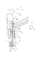
Установка 100, представленная на фиг. 1, предназначена для электростатического нанесения покрывающего материала на объект (на чертеже не показан). Указанная установка 100 содержит распылитель 1 для электростатического напыления покрывающего материала, подаваемого посредством шланга 21 из резервуара 20.
Распылитель 1, к тому же, соединен шлангом 31 с источником 30 сжатого воздуха. Под действием воздуха, поступающего из источника 30, покрывающий материал распыляется и направляется от распылителя 1 к покрываемому объекту.The atomizer 1, moreover, is connected by a
Ссылочной позицией 2 в распылителе 1 обозначен проточный канал для покрывающего материала.
Ссылочной позицией 4 обозначена полость ствола 13 распылителя 1, в которой перемещается игла 3, когда оператор нажимает на спусковой механизм 6 распылителя 1 или отпускает спусковой механизм 6. Полость 4 имеет поверхность S4, служащую направляющей для иглы 3, перемещающейся вдоль продольной оси Y4 полости 4. Поверхность S4 является цилиндрической с круглым основанием.
Игла 3 имеет, в основном, цилиндрическую форму, за исключением переднего конца 3a, который представляет собой конусообразный наконечник, расположенный рядом с распылительным отверстием S для покрывающего материала. Игла 3, к тому же, содержит заднюю часть 3c, соединенную со спусковым механизмом 6, и центральную часть 3b, продолжающуюся от переднего конца 3a к задней части 3c. Игла 3 перемещается под действием спускового механизма 6, соединенного с задней частью 3c иглы.The
Три разные части иглы 3 изготовлены из разных материалов. Передний конец 3a иглы 3, к которому подводится высокое напряжение, изготовлен из электропроводного материала, имеющего высокую твердость по Шору, которая, в частности, превышает или равна 55 HRC. На фиг. 1, 2 и 3 конец 3a иглы показан точечной штриховкой. Центральная часть 3b иглы изготовлена из изоляционного материала, в то время как задняя часть 3c иглы 3, показанная линейной штриховкой на фиг. 1, 2 и 3, изготовлена из электропроводного материала, имеющего высокую твердость. Части 3a и 3b могут быть изготовлены из одинаковых или разных материалов.Three different parts of the
Полость 4, в которой распложена игла 3, содержит первую канавку 4a, расположенную вблизи выходного отверстия S и переднего конца 3a иглы, конкретнее, вблизи места соединения переднего конца 3a с центральной частью 3b иглы 3. В канавке 4a установлено первое уплотнение 41, окружающее иглу 3, которая подвижно контактирует с указанным уплотнением. Указанное уплотнение 41 обеспечивает герметизацию полости 4 относительно среды, окружающей распылитель, а также относительно покрывающего материала, который подается по каналу 2 и во время распыления контактирует с концом 3a иглы 3. Кроме того, в полости 4 выполнена вторая канавка 4b, расположенная вблизи спускового механизма 6 и задней части 3c иглы, конкретнее говоря, противоположно первой канавке 4a. В канавке 4b установлено второе уплотнение 42, окружающее иглу 3, которая подвижно контактирует с указанным уплотнением. Указанное второе уплотнение 42 надежно герметизирует полость 4 от проникновения посторонних веществ снаружи, таких как пыль, растворители или остатки краски. Чтобы уплотнения 41 и 42 создавали надежную опору для иглы 3, указанные уплотнения изготовлены из материалов, адаптированных к материалу(ам), из которого(ых) изготовлен(ы) конец 3a и задняя часть 3c иглы.The
Ссылочной позицией 5 в распылителе 1 обозначен воздушный канал. Указанный канал 5 содержит первую секцию 5a и вторую секцию 5b, между которыми установлен клапан 7, регулирующий поток воздуха. Вторая секция 5b заканчивается на выходном отверстии S вблизи конца 3a иглы 3.Reference numeral 5 in the atomizer 1 indicates an air passage. The specified channel 5 contains a
Воздушный клапан 7 содержит затвор 7a, который имеет фору, согласующуюся с седлом 7b, и упирается в него под действием возвратного усилия R пружины 50, удерживаемой в требуемом положении стопором 51, обеспечивающим для указанной пружины 50 неподвижную опору. Затвор 7a связан с перемещающейся иглой 3. Таким образом, когда к спусковому механизму 6 распылителя 1 не прикладывается сила, пружина 50 удерживает иглу 3 в положении, при котором она закрывает проход для потока покрывающего материала, подаваемого по каналу 2 к выходному отверстию S. Точнее говоря, под действием возвратного усилия R согласующийся с седлом 33 передний конец 3a иглы 3 упирается в указанное седло 33. Таким образом, игла 3 и седло 33 совместно образуют клапан 63, который регулирует поток покрывающего материала.The
Спусковой механизм 6 может поворачиваться в корпусе 15 распылителя вокруг оси X6, перпендикулярной оси Y4. Указанный спусковой механизм предназначен открывать и закрывать клапан 7, перемещая иглу 3 параллельно оси Y4. Конкретнее, спусковой механизм 6 надавливает на затвор 7a, подвергая его действию силы противоположной возвратному усилию R пружины, в результате чего, затвор 7a смещается относительно седла 7b вдоль оси Y4. При этом игла 3 перемещается параллельно оси Y4. Когда оператор отпускает спусковой механизм 6, пружина 50 толкает затвор 7b и иглу 3 обратно в положение, при котором прерывается поступающий по воздушному каналу 5 поток воздуха, а также поступающий по каналу 2 поток покрывающего материала. Таким образом, посредством спускового механизма 6 регулируется поток покрывающего материала и поток сжатого воздуха, которые подаются по соответствующим поточным каналам 2 и 5.The
Высоковольтный блок 12, расположенный в стволе 13 распылителя 1, соединен посредством электрического кабеля 11 с генератором 10, который снабжает его током. Генератор 10 посредством кабеля 17 подсоединяется к сети, снабжающей его током.The high-
Высоковольтный блок 12 электрически соединен с концом 3a иглы 3 с помощью специальных средств (не показанных на чертежах), передающих к указанному концу иглы высокое напряжение, конкретнее говоря, на конце иглы создается электрический потенциал, абсолютная величина которого составляет от 10 кВ до 200 кВ.The high-
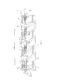
Вдоль наружного контура центральной части 3b иглы 3, расположенной в полости 4, равномерно распределены первые механически обработанные участки 8. Центральная часть иглы имеет цилиндрическую огибающую поверхность S3b с круглым основанием и диаметром D3. Первые механически обработанные участки 8 формируют впадины относительно огибающей поверхности S3b иглы 3, диаметр D8 которых меньше диаметра D3 огибающей поверхности S3b. Диаметр D8 впадин, сформированных первыми механически обработанными участками, составляет, предпочтительно, от 15% до 60% диаметра D3 огибающей поверхности S3b.The first
Ссылочной позицией U8 обозначена длина первого механически обработанного участка 8, измеренная параллельно оси Y4, вдоль которой продолжается каждый из указанных участков.Reference numeral U8 denotes the length of the first
Следует отметить, что в полости 4 расположены вторые механически обработанные участки 9, противолежащие первым механически обработанным участкам 8. Вторые механически обработанные участки 9 формируют впадины относительно направляющей поверхности S4 для перемещающейся иглы 3. Диаметр D9 впадин, сформированных вторыми механически обработанными участками 9, больше диаметра D4 направляющей поверхности S4 для перемещающейся иглы 3. Диаметр D9 впадин составляет, предпочтительно, от 101% до 200% диаметра D4 поверхности S4.It should be noted that in the
Ссылочной позицией U9 обозначена длина каждого второго механически обработанного участка 9, измеренная параллельно оси Y4, вдоль которой продолжаются указанные участки.Reference numeral U9 denotes the length of each second
Каждый первый механически обработанный участок 8 продолжается параллельно оси Y4 и имеет длину U8. Сумма длин U8 первых механически обработанных участков составляет от 10% до 50% длины U3b центральной части 3b иглы 3, измеренной параллельно оси Y4.Each first
Длина U9 каждого второго механически обработанного участка больше длины U8. Предпочтительно, длина U9 составляет от 120% до 200% длины U8. За счет первых механически обработанных участков 8 и вторых механически обработанных участков 9 можно удлинить путь утечки тока по сравнению с конструкцией, при которой игла и полость не содержат механически обработанных участков, благодаря чему, при приложении к концу 3a иглы 3 высокого напряжения электрический потенциал спускового механизма 6 и задней части 16 распылителя 1 не отличается от потенциала земли.The length U9 of each second machined portion is greater than the length U8. Preferably, the length of U9 is from 120% to 200% of the length of U8. Due to the first
Кроме того, поскольку длина U9 вторых механически обработанных участков 9 больше длины U8 первых механически обработанных участков 8, длина пути утечки тока не зависит от положения иглы 3 в полости 4.In addition, since the length U9 of the second
К тому же, между иглой 3 и полостью 4 создается свободный объем V1, который заполняют электроизоляционным материалом. В качестве электроизоляционного материала используется трансформаторное масло. Благодаря электроизоляционным свойствам указанного масла дополнительно удлиняется путь утечки тока между передним концом 3a и задней частью 3c иглы, следовательно, можно изготовить более короткий ствол распылителя, чем это возможно, исходя из характерных свойств материалов, применяемых для изготовления ствола 13 и иглы 3. Кроме того, указанный электроизоляционный материал предотвращает образование озона. В действительности, если не применяется изоляционный материал, воздух, заключенный между иглой 3 и полостью 4 ствола 13 быстро ионизируется с образованием озона. Образовавшийся озон является газом, вредным для здоровья, кроме того, способен вызвать коррозию материала иглы 3 и полости 4, приводящую, в конечном счете, к утечке тока, представляющей опасность для оператора, использующего ручной распылитель 1.In addition, a free volume V1 is created between the
В представленном на фиг. 4 распылителе согласно второму варианту осуществления изобретения игла 203 в целом подобна игле 3 распылителя согласно первому варианту осуществления изобретения, однако содержит видоизмененные первые механически обработанные участки 208.In the embodiment of FIG. 4 of the nozzle according to the second embodiment of the invention, the
Ссылочные позиции элементов второго варианта распылителя, подобных элементам первого варианта распылителя, увеличены на 200.The reference position of the elements of the second variant of the atomizer, similar to the elements of the first variant of the atomizer, is increased by 200.
Далее описываются отличия второго варианта распылителя от первого варианта распылителя.The following describes the differences between the second variant of the atomizer and the first variant of the atomizer.
Следует отметить, что первые механически обработанные участки 208 формируют спиралевидные впадины относительно огибающей поверхности S203b центральной части 203b иглы 203. Таким образом, первые механически обработанные участки образуют первую углубленную спираль относительно огибающей поверхности S203b центральной части 203b иглы 203. Вторые механически обработанные участки расположенные в полости ствола (не показано), расположенные напротив первых механически обработанных участков 208, образуют вторую углубленную спираль относительно направляющей поверхности для перемещающейся иглы 203.It should be noted that the first
В представленном на фиг. 5 и 6 распылителе согласно третьему варианту осуществления настоящего изобретения игла 303, в целом, подобна игле 203 распылителя согласно второму варианту осуществления изобретения, однако содержит первые выступы 308, которые отличаются от первых механически обработанных участков 208. Подобные элементы третьего варианта распылителя и первого варианта распылителя имеют подобные ссылочные позиции. Далее описываются отличия третьего варианта распылителя от первого варианта распылителя.In the embodiment of FIG. 5 and 6 of the sprayer according to the third embodiment of the present invention, the
Первые выступы 308 образуют спираль, продолжающуюся вокруг центральной части 303b иглы 303. Конкретнее говоря, центральная часть 303b иглы содержит участок 314, который, в основном, является цилиндрическим, причем первые выступы 308 выдаются из цилиндрического участка 314. Ссылочной позицией D314 обозначен диаметр цилиндрического участка 314, а ссылочной позицией D308 обозначен диаметр первого выступа 308.The
Диаметр D308 спирали, сформированной первыми выступами 308, больше диаметра D314 цилиндрического участка 314. Диаметр D314, предпочтительно, составляет от 15% до 60% диаметра D308.The diameter D308 of the spiral formed by the
Кроме того, так же как и во втором варианте распылителя, полость ствола 13 содержит вторые механически обработанные участки 309, расположенные напротив первых выступов 308 и формирующие вторую углубленную спираль относительно направляющей поверхности S4 для перемещающейся иглы 303.In addition, as in the second sprayer embodiment, the
Ссылочной позицией U308 обозначена первая ширина выступающей спирали 308, которая измерена вдоль оси Y4. Первая ширина U308, в общем, является постоянной вокруг центрального участка 303b.Reference numeral U308 denotes the first width of the protruding
Ссылочной позицией U309 обозначена вторая ширина второй углубленной спирали 309, которая измерена вдоль оси Y4. Вторая ширина U309, в общем, является постоянной вдоль полости 4.Reference numeral U309 denotes the second width of the second recessed
Выступающая спираль 308 и вторая углубленная спираль 309 имеют сопрягаемые формы, например, выступающая спираль 308 может вворачиваться во вторую углубленную спираль 309. Кроме того, выступающая спираль 308 и вторая углубленная спираль 309 имеют одинаковое направление.The protruding
Первая ширина U308 составляет от 10% до 50% второй ширины U309. Конкретнее, вторая ширина U309 больше первой ширины U308, причем вторая ширина U309 превышает сумму первой ширины U308 и длины продольного хода иглы 303. Под длиной продольного хода иглы 303 подразумевается расстояние, на которое перемещается игла 303 вдоль продольной оси Y4 между ее положением при освобожденном спусковом механизме 6 распылителя 1 и положением при полностью активизированном спусковом механизме 6.The first width of U308 is from 10% to 50% of the second width of U309. More specifically, the second width U309 is greater than the first width U308, and the second width U309 exceeds the sum of the first width U308 and the length of the longitudinal stroke of the
Альтернативно, первые и вторые механически обработанные участки образуют впадины любой формы.Alternatively, the first and second machined sections form hollows of any shape.
Согласно другой альтернативе, игла 203 во втором варианте распылителя содержит единственный механически обработанный участок, образующий первую углубленную спираль.According to another alternative, the
Согласно еще одной альтернативе, игла 303 в третьем варианте распылителя содержит единственный первый выступ, образующий выступающую спираль.According to yet another alternative, the
Согласно другой альтернативе, механически обработанные участки располагаются неравномерно вдоль центральной части 3b иглы 3 и полости 4.According to another alternative, the machined sections are not evenly distributed along the
Согласно еще одной альтернативе, генератор 10 снабжается током из автономного источника.According to another alternative, the
Согласно другой альтернативе, во втором и третьем вариантах распылителя полость 4 содержит единственный второй механически обработанный участок, образующий вторую углубленную спираль.According to another alternative, in the second and third embodiments of the
Согласно следующей альтернативе, выступающая спираль 308 и вторая углубленная спираль 309 в третьем варианте распылителя имеют противоположные направления.According to a further alternative, the protruding
Согласно другой альтернативе, игла и полость имеют сопрягаемые формы, которые не являются цилиндрическими.According to another alternative, the needle and cavity have mating shapes that are not cylindrical.
Согласно еще одной альтернативе, впадины сформированы выступающими элементами иглы 3 и полости 4. В этом случае указанные элементы формируют одну часть иглы 3 или полости 4, либо являются частями, закрепленными на игле 3 или полости 4.According to another alternative, the depressions are formed by the protruding elements of the
На фиг. 1 иллюстративный распылитель 1 является ручным распылителем для электростатического напыления покрывающего материала. Альтернативно, указанный распылитель представляет собой автоматический распылитель для напыления покрывающего материала.In FIG. 1 illustrative atomizer 1 is a manual atomizer for electrostatically spraying a coating material. Alternatively, said sprayer is an automatic sprayer for spraying coating material.
Раскрытые выше технические признаки вариантов осуществления изобретения и его аспектов могут сочетаться друг с другом для создания других вариантов осуществления изобретения.The technical features disclosed above and embodiments of the invention and its aspects can be combined with each other to create other embodiments of the invention.
Claims (17)
Applications Claiming Priority (3)
| Application Number | Priority Date | Filing Date | Title |
|---|---|---|---|
| FR1356727 | 2013-07-09 | ||
| FR1356727A FR3008328B1 (en) | 2013-07-09 | 2013-07-09 | ELECTROSTATIC COATING PRODUCT SPRAY SPRAYER AND COATING PRODUCT PROJECTION INSTALLATION COMPRISING SUCH A SPRAYER |
| PCT/EP2014/064554 WO2015004111A1 (en) | 2013-07-09 | 2014-07-08 | Spray nozzle for electrostatic spraying of a coating product and facility for spraying a coating product including such a spray nozzle |
Publications (3)
| Publication Number | Publication Date |
|---|---|
| RU2016104058A RU2016104058A (en) | 2017-08-14 |
| RU2016104058A3 RU2016104058A3 (en) | 2018-03-29 |
| RU2662503C2 true RU2662503C2 (en) | 2018-07-26 |
Family
ID=49212925
Family Applications (1)
| Application Number | Title | Priority Date | Filing Date |
|---|---|---|---|
| RU2016104058A RU2662503C2 (en) | 2013-07-09 | 2014-07-08 | Coating material electrostatic coating sprayer and containing the said sprayer installation |
Country Status (12)
| Country | Link |
|---|---|
| US (1) | US10549291B2 (en) |
| EP (1) | EP3019278B1 (en) |
| JP (1) | JP6411488B2 (en) |
| KR (1) | KR102181164B1 (en) |
| CN (1) | CN105377442B (en) |
| BR (1) | BR112015032228A2 (en) |
| ES (1) | ES2759866T3 (en) |
| FR (1) | FR3008328B1 (en) |
| PL (1) | PL3019278T3 (en) |
| PT (1) | PT3019278T (en) |
| RU (1) | RU2662503C2 (en) |
| WO (1) | WO2015004111A1 (en) |
Families Citing this family (1)
| Publication number | Priority date | Publication date | Assignee | Title |
|---|---|---|---|---|
| CN113617546A (en) * | 2021-09-01 | 2021-11-09 | 浙江国达智能机电装备科技有限公司 | An electrostatic powder spraying equipment |
Citations (5)
| Publication number | Priority date | Publication date | Assignee | Title |
|---|---|---|---|---|
| DE4106564A1 (en) * | 1991-03-01 | 1992-09-03 | Bosch Gmbh Robert | Electrostatic liq. jet atomiser featuring corona discharge ring - facilitates control of spray by neutralisation of charged droplets ejected into cloud of oppositely charged ions |
| RU2115487C1 (en) * | 1996-12-23 | 1998-07-20 | Юрий Евгеньевич Ключарев | Electrostatic spraying gun for powdered materials |
| WO2001066261A2 (en) * | 2000-03-09 | 2001-09-13 | Nordson Corporation | Modular fluid spray gun |
| JP2008290046A (en) * | 2007-05-28 | 2008-12-04 | Abb Kk | Electrostatic coating equipment |
| RU113981U1 (en) * | 2011-08-25 | 2012-03-10 | Федеральное государственное бюджетное образовательное учреждение высшего профессионального образования "Казанский национальный исследовательский технический университет им. А.Н. Туполева - КАИ" (КНИТУ - КАИ) | DEVICE FOR APPLICATION OF MICROSPHERIC LIGHT-RETURNING PARTICLES IN AN ELECTROSTATIC FIELD |
Family Cites Families (13)
| Publication number | Priority date | Publication date | Assignee | Title |
|---|---|---|---|---|
| US3056557A (en) * | 1959-07-16 | 1962-10-02 | Arvid C Walberg | Spray gun for electrostatic coating |
| US3583632A (en) * | 1969-05-23 | 1971-06-08 | Binks Mfg Co | Electrostatic spray coating apparatus |
| CN2061091U (en) * | 1990-01-24 | 1990-08-29 | 沈阳长征静电喷漆机厂 | Hydraulic electrostatic paint spraying machine |
| JPH0587017A (en) | 1991-09-27 | 1993-04-06 | Hitachi Ltd | Assist air control device |
| US6131820A (en) * | 1999-06-01 | 2000-10-17 | Calmar Inc. | Discharge valve assembly for trigger sprayer |
| EP1566222B1 (en) * | 2002-10-31 | 2012-08-29 | Anest Iwata Corporation | Spray gun for electrostatic painting |
| US7793869B2 (en) * | 2003-08-18 | 2010-09-14 | Nordson Corporation | Particulate material applicator and pump |
| JP5086680B2 (en) * | 2007-03-30 | 2012-11-28 | 本田技研工業株式会社 | Electrostatic coating equipment |
| JP4347372B2 (en) * | 2007-08-10 | 2009-10-21 | トヨタ自動車株式会社 | Electrostatic coating equipment |
| KR20090073636A (en) * | 2007-12-31 | 2009-07-03 | 엘지전자 주식회사 | Electrostatic spray bulkhead coating device and method |
| US8016213B2 (en) * | 2008-03-10 | 2011-09-13 | Illinois Tool Works Inc. | Controlling temperature in air-powered electrostatically aided coating material atomizer |
| KR100920769B1 (en) * | 2008-03-11 | 2009-10-08 | 연세대학교 산학협력단 | Electro-Hydraulic Injection Nozzle, Injector and Patterning Method Using the Same |
| JP2009220034A (en) * | 2008-03-17 | 2009-10-01 | Asahi Sunac Corp | Coating gun |
-
2013
- 2013-07-09 FR FR1356727A patent/FR3008328B1/en not_active Expired - Fee Related
-
2014
- 2014-07-08 RU RU2016104058A patent/RU2662503C2/en active
- 2014-07-08 PL PL14738474T patent/PL3019278T3/en unknown
- 2014-07-08 US US14/901,896 patent/US10549291B2/en active Active
- 2014-07-08 BR BR112015032228A patent/BR112015032228A2/en not_active Application Discontinuation
- 2014-07-08 WO PCT/EP2014/064554 patent/WO2015004111A1/en not_active Ceased
- 2014-07-08 PT PT147384747T patent/PT3019278T/en unknown
- 2014-07-08 ES ES14738474T patent/ES2759866T3/en active Active
- 2014-07-08 EP EP14738474.7A patent/EP3019278B1/en active Active
- 2014-07-08 KR KR1020157036652A patent/KR102181164B1/en active Active
- 2014-07-08 JP JP2016524792A patent/JP6411488B2/en active Active
- 2014-07-08 CN CN201480039032.0A patent/CN105377442B/en active Active
Patent Citations (5)
| Publication number | Priority date | Publication date | Assignee | Title |
|---|---|---|---|---|
| DE4106564A1 (en) * | 1991-03-01 | 1992-09-03 | Bosch Gmbh Robert | Electrostatic liq. jet atomiser featuring corona discharge ring - facilitates control of spray by neutralisation of charged droplets ejected into cloud of oppositely charged ions |
| RU2115487C1 (en) * | 1996-12-23 | 1998-07-20 | Юрий Евгеньевич Ключарев | Electrostatic spraying gun for powdered materials |
| WO2001066261A2 (en) * | 2000-03-09 | 2001-09-13 | Nordson Corporation | Modular fluid spray gun |
| JP2008290046A (en) * | 2007-05-28 | 2008-12-04 | Abb Kk | Electrostatic coating equipment |
| RU113981U1 (en) * | 2011-08-25 | 2012-03-10 | Федеральное государственное бюджетное образовательное учреждение высшего профессионального образования "Казанский национальный исследовательский технический университет им. А.Н. Туполева - КАИ" (КНИТУ - КАИ) | DEVICE FOR APPLICATION OF MICROSPHERIC LIGHT-RETURNING PARTICLES IN AN ELECTROSTATIC FIELD |
Also Published As
| Publication number | Publication date |
|---|---|
| RU2016104058A (en) | 2017-08-14 |
| WO2015004111A1 (en) | 2015-01-15 |
| CN105377442A (en) | 2016-03-02 |
| EP3019278A1 (en) | 2016-05-18 |
| FR3008328A1 (en) | 2015-01-16 |
| KR20160030118A (en) | 2016-03-16 |
| FR3008328B1 (en) | 2015-07-24 |
| PT3019278T (en) | 2020-01-14 |
| KR102181164B1 (en) | 2020-11-20 |
| BR112015032228A2 (en) | 2017-07-25 |
| JP2016523706A (en) | 2016-08-12 |
| EP3019278B1 (en) | 2019-10-30 |
| CN105377442B (en) | 2018-04-20 |
| ES2759866T3 (en) | 2020-05-12 |
| RU2016104058A3 (en) | 2018-03-29 |
| US20160368007A1 (en) | 2016-12-22 |
| US10549291B2 (en) | 2020-02-04 |
| PL3019278T3 (en) | 2020-05-18 |
| JP6411488B2 (en) | 2018-10-24 |
Similar Documents
| Publication | Publication Date | Title |
|---|---|---|
| US20180141062A1 (en) | Electrode assembly for an electrostatic atomizer | |
| US7748651B2 (en) | Electrostatic coating spray gun | |
| JPS60244358A (en) | Multi-treatment possible electrostatic spray gun with power supply part | |
| JPS6123031B2 (en) | ||
| US7552882B2 (en) | Spray gun for electrostatic painting | |
| CA2595147A1 (en) | Electrostatic coating device | |
| EP2903748B1 (en) | Spray tip assembly for electrostatic spray gun | |
| JP2006051427A (en) | Electrostatic coating spray gun and electrostatic coating method | |
| RU2662503C2 (en) | Coating material electrostatic coating sprayer and containing the said sprayer installation | |
| US20150060579A1 (en) | Electrostatic Spray System | |
| US20150231652A1 (en) | Grounding rods for electrostatic spray | |
| JP2010064035A (en) | Electrostatic ejection apparatus | |
| HU181198B (en) | Electroacoustic paint sprayer | |
| JPS6158231B2 (en) | ||
| JPH043640Y2 (en) | ||
| JP7572718B2 (en) | Electrostatic spray gun | |
| JPH043641Y2 (en) | ||
| JPS6212419Y2 (en) | ||
| JPH0487650A (en) | Electrostatic spray gun | |
| JP3331271B2 (en) | Paint passage for air atomizing automatic electrostatic spray gun | |
| JPS6212418Y2 (en) | ||
| US10471447B2 (en) | Cascade system | |
| JPH0534778Y2 (en) | ||
| KR20210115302A (en) | Spray device | |
| CA1164198A (en) | Electrostatic spray gun |