RU2657953C2 - Inline adapter for respiratory therapy device - Google Patents
Inline adapter for respiratory therapy device Download PDFInfo
- Publication number
- RU2657953C2 RU2657953C2 RU2015129059A RU2015129059A RU2657953C2 RU 2657953 C2 RU2657953 C2 RU 2657953C2 RU 2015129059 A RU2015129059 A RU 2015129059A RU 2015129059 A RU2015129059 A RU 2015129059A RU 2657953 C2 RU2657953 C2 RU 2657953C2
- Authority
- RU
- Russia
- Prior art keywords
- tube assembly
- adapter
- heated tube
- pressure generating
- housing
- Prior art date
Links
Images

Classifications
-
- A—HUMAN NECESSITIES
- A61—MEDICAL OR VETERINARY SCIENCE; HYGIENE
- A61M—DEVICES FOR INTRODUCING MEDIA INTO, OR ONTO, THE BODY; DEVICES FOR TRANSDUCING BODY MEDIA OR FOR TAKING MEDIA FROM THE BODY; DEVICES FOR PRODUCING OR ENDING SLEEP OR STUPOR
- A61M16/00—Devices for influencing the respiratory system of patients by gas treatment, e.g. mouth-to-mouth respiration; Tracheal tubes
- A61M16/08—Bellows; Connecting tubes ; Water traps; Patient circuits
- A61M16/0816—Joints or connectors
-
- A—HUMAN NECESSITIES
- A61—MEDICAL OR VETERINARY SCIENCE; HYGIENE
- A61M—DEVICES FOR INTRODUCING MEDIA INTO, OR ONTO, THE BODY; DEVICES FOR TRANSDUCING BODY MEDIA OR FOR TAKING MEDIA FROM THE BODY; DEVICES FOR PRODUCING OR ENDING SLEEP OR STUPOR
- A61M15/00—Inhalators
- A61M15/08—Inhaling devices inserted into the nose
-
- A—HUMAN NECESSITIES
- A61—MEDICAL OR VETERINARY SCIENCE; HYGIENE
- A61M—DEVICES FOR INTRODUCING MEDIA INTO, OR ONTO, THE BODY; DEVICES FOR TRANSDUCING BODY MEDIA OR FOR TAKING MEDIA FROM THE BODY; DEVICES FOR PRODUCING OR ENDING SLEEP OR STUPOR
- A61M16/00—Devices for influencing the respiratory system of patients by gas treatment, e.g. mouth-to-mouth respiration; Tracheal tubes
- A61M16/0057—Pumps therefor
-
- A—HUMAN NECESSITIES
- A61—MEDICAL OR VETERINARY SCIENCE; HYGIENE
- A61M—DEVICES FOR INTRODUCING MEDIA INTO, OR ONTO, THE BODY; DEVICES FOR TRANSDUCING BODY MEDIA OR FOR TAKING MEDIA FROM THE BODY; DEVICES FOR PRODUCING OR ENDING SLEEP OR STUPOR
- A61M16/00—Devices for influencing the respiratory system of patients by gas treatment, e.g. mouth-to-mouth respiration; Tracheal tubes
- A61M16/06—Respiratory or anaesthetic masks
- A61M16/0666—Nasal cannulas or tubing
-
- A—HUMAN NECESSITIES
- A61—MEDICAL OR VETERINARY SCIENCE; HYGIENE
- A61M—DEVICES FOR INTRODUCING MEDIA INTO, OR ONTO, THE BODY; DEVICES FOR TRANSDUCING BODY MEDIA OR FOR TAKING MEDIA FROM THE BODY; DEVICES FOR PRODUCING OR ENDING SLEEP OR STUPOR
- A61M16/00—Devices for influencing the respiratory system of patients by gas treatment, e.g. mouth-to-mouth respiration; Tracheal tubes
- A61M16/08—Bellows; Connecting tubes ; Water traps; Patient circuits
- A61M16/0816—Joints or connectors
- A61M16/0833—T- or Y-type connectors, e.g. Y-piece
-
- A—HUMAN NECESSITIES
- A61—MEDICAL OR VETERINARY SCIENCE; HYGIENE
- A61M—DEVICES FOR INTRODUCING MEDIA INTO, OR ONTO, THE BODY; DEVICES FOR TRANSDUCING BODY MEDIA OR FOR TAKING MEDIA FROM THE BODY; DEVICES FOR PRODUCING OR ENDING SLEEP OR STUPOR
- A61M16/00—Devices for influencing the respiratory system of patients by gas treatment, e.g. mouth-to-mouth respiration; Tracheal tubes
- A61M16/08—Bellows; Connecting tubes ; Water traps; Patient circuits
- A61M16/0875—Connecting tubes
-
- A—HUMAN NECESSITIES
- A61—MEDICAL OR VETERINARY SCIENCE; HYGIENE
- A61M—DEVICES FOR INTRODUCING MEDIA INTO, OR ONTO, THE BODY; DEVICES FOR TRANSDUCING BODY MEDIA OR FOR TAKING MEDIA FROM THE BODY; DEVICES FOR PRODUCING OR ENDING SLEEP OR STUPOR
- A61M16/00—Devices for influencing the respiratory system of patients by gas treatment, e.g. mouth-to-mouth respiration; Tracheal tubes
- A61M16/10—Preparation of respiratory gases or vapours
- A61M16/1075—Preparation of respiratory gases or vapours by influencing the temperature
- A61M16/1095—Preparation of respiratory gases or vapours by influencing the temperature in the connecting tubes
-
- A—HUMAN NECESSITIES
- A61—MEDICAL OR VETERINARY SCIENCE; HYGIENE
- A61M—DEVICES FOR INTRODUCING MEDIA INTO, OR ONTO, THE BODY; DEVICES FOR TRANSDUCING BODY MEDIA OR FOR TAKING MEDIA FROM THE BODY; DEVICES FOR PRODUCING OR ENDING SLEEP OR STUPOR
- A61M16/00—Devices for influencing the respiratory system of patients by gas treatment, e.g. mouth-to-mouth respiration; Tracheal tubes
- A61M16/0057—Pumps therefor
- A61M16/0066—Blowers or centrifugal pumps
-
- A—HUMAN NECESSITIES
- A61—MEDICAL OR VETERINARY SCIENCE; HYGIENE
- A61M—DEVICES FOR INTRODUCING MEDIA INTO, OR ONTO, THE BODY; DEVICES FOR TRANSDUCING BODY MEDIA OR FOR TAKING MEDIA FROM THE BODY; DEVICES FOR PRODUCING OR ENDING SLEEP OR STUPOR
- A61M16/00—Devices for influencing the respiratory system of patients by gas treatment, e.g. mouth-to-mouth respiration; Tracheal tubes
- A61M16/06—Respiratory or anaesthetic masks
-
- A—HUMAN NECESSITIES
- A61—MEDICAL OR VETERINARY SCIENCE; HYGIENE
- A61M—DEVICES FOR INTRODUCING MEDIA INTO, OR ONTO, THE BODY; DEVICES FOR TRANSDUCING BODY MEDIA OR FOR TAKING MEDIA FROM THE BODY; DEVICES FOR PRODUCING OR ENDING SLEEP OR STUPOR
- A61M16/00—Devices for influencing the respiratory system of patients by gas treatment, e.g. mouth-to-mouth respiration; Tracheal tubes
- A61M16/10—Preparation of respiratory gases or vapours
- A61M16/105—Filters
- A61M16/1055—Filters bacterial
-
- A—HUMAN NECESSITIES
- A61—MEDICAL OR VETERINARY SCIENCE; HYGIENE
- A61M—DEVICES FOR INTRODUCING MEDIA INTO, OR ONTO, THE BODY; DEVICES FOR TRANSDUCING BODY MEDIA OR FOR TAKING MEDIA FROM THE BODY; DEVICES FOR PRODUCING OR ENDING SLEEP OR STUPOR
- A61M16/00—Devices for influencing the respiratory system of patients by gas treatment, e.g. mouth-to-mouth respiration; Tracheal tubes
- A61M16/10—Preparation of respiratory gases or vapours
- A61M16/12—Preparation of respiratory gases or vapours by mixing different gases
-
- A—HUMAN NECESSITIES
- A61—MEDICAL OR VETERINARY SCIENCE; HYGIENE
- A61M—DEVICES FOR INTRODUCING MEDIA INTO, OR ONTO, THE BODY; DEVICES FOR TRANSDUCING BODY MEDIA OR FOR TAKING MEDIA FROM THE BODY; DEVICES FOR PRODUCING OR ENDING SLEEP OR STUPOR
- A61M16/00—Devices for influencing the respiratory system of patients by gas treatment, e.g. mouth-to-mouth respiration; Tracheal tubes
- A61M16/20—Valves specially adapted to medical respiratory devices
- A61M16/208—Non-controlled one-way valves, e.g. exhalation, check, pop-off non-rebreathing valves
-
- A—HUMAN NECESSITIES
- A61—MEDICAL OR VETERINARY SCIENCE; HYGIENE
- A61M—DEVICES FOR INTRODUCING MEDIA INTO, OR ONTO, THE BODY; DEVICES FOR TRANSDUCING BODY MEDIA OR FOR TAKING MEDIA FROM THE BODY; DEVICES FOR PRODUCING OR ENDING SLEEP OR STUPOR
- A61M39/00—Tubes, tube connectors, tube couplings, valves, access sites or the like, specially adapted for medical use
- A61M39/10—Tube connectors; Tube couplings
- A61M2039/1022—Tube connectors; Tube couplings additionally providing electrical connection
-
- A—HUMAN NECESSITIES
- A61—MEDICAL OR VETERINARY SCIENCE; HYGIENE
- A61M—DEVICES FOR INTRODUCING MEDIA INTO, OR ONTO, THE BODY; DEVICES FOR TRANSDUCING BODY MEDIA OR FOR TAKING MEDIA FROM THE BODY; DEVICES FOR PRODUCING OR ENDING SLEEP OR STUPOR
- A61M2202/00—Special media to be introduced, removed or treated
- A61M2202/02—Gases
- A61M2202/0208—Oxygen
-
- A—HUMAN NECESSITIES
- A61—MEDICAL OR VETERINARY SCIENCE; HYGIENE
- A61M—DEVICES FOR INTRODUCING MEDIA INTO, OR ONTO, THE BODY; DEVICES FOR TRANSDUCING BODY MEDIA OR FOR TAKING MEDIA FROM THE BODY; DEVICES FOR PRODUCING OR ENDING SLEEP OR STUPOR
- A61M2205/00—General characteristics of the apparatus
- A61M2205/36—General characteristics of the apparatus related to heating or cooling
-
- A—HUMAN NECESSITIES
- A61—MEDICAL OR VETERINARY SCIENCE; HYGIENE
- A61M—DEVICES FOR INTRODUCING MEDIA INTO, OR ONTO, THE BODY; DEVICES FOR TRANSDUCING BODY MEDIA OR FOR TAKING MEDIA FROM THE BODY; DEVICES FOR PRODUCING OR ENDING SLEEP OR STUPOR
- A61M2205/00—General characteristics of the apparatus
- A61M2205/50—General characteristics of the apparatus with microprocessors or computers
-
- A—HUMAN NECESSITIES
- A61—MEDICAL OR VETERINARY SCIENCE; HYGIENE
- A61M—DEVICES FOR INTRODUCING MEDIA INTO, OR ONTO, THE BODY; DEVICES FOR TRANSDUCING BODY MEDIA OR FOR TAKING MEDIA FROM THE BODY; DEVICES FOR PRODUCING OR ENDING SLEEP OR STUPOR
- A61M2205/00—General characteristics of the apparatus
- A61M2205/75—General characteristics of the apparatus with filters
- A61M2205/7518—General characteristics of the apparatus with filters bacterial
-
- A—HUMAN NECESSITIES
- A61—MEDICAL OR VETERINARY SCIENCE; HYGIENE
- A61M—DEVICES FOR INTRODUCING MEDIA INTO, OR ONTO, THE BODY; DEVICES FOR TRANSDUCING BODY MEDIA OR FOR TAKING MEDIA FROM THE BODY; DEVICES FOR PRODUCING OR ENDING SLEEP OR STUPOR
- A61M2210/00—Anatomical parts of the body
- A61M2210/10—Trunk
- A61M2210/1042—Alimentary tract
- A61M2210/1046—Pharynx
Abstract
Description
УРОВЕНЬ ТЕХНИКИ ИЗОБРЕТЕНИЯBACKGROUND OF THE INVENTION
1. ОБЛАСТЬ ТЕХНИКИ, К КОТОРОЙ ОТНОСИТСЯ ИЗОБРЕТЕНИЕ1. FIELD OF THE INVENTION
Настоящее изобретение относится к системам для лечения состояний, таких как нарушение дыхания во сне, использующих лечение положительным давлением в дыхательных путях (PAP), и, в частности, к встраиваемому адаптеру для устройства поддержки давлением, который делает возможным электрическое соединение, которое нужно сделать между электрооборудованием (например, подогреваемым шлангом) и устройством поддержки давлением.The present invention relates to systems for treating conditions, such as sleep disturbance, using positive airway pressure treatment (PAP), and in particular, to an integrated adapter for a pressure support device that enables an electrical connection to be made between electrical equipment (such as a heated hose) and pressure support device.
2. Описание уровня техники2. Description of the prior art
Есть множество ситуаций, когда необходимо или желательно неинвазивно доставить поток дыхательного газа в дыхательные пути пациента, т.е. без интубации пациента или вставки путем хирургического вмешательства трахеальной трубки в пищевод пациента. Например, известно, как вентилировать пациента, используя метод, известный как неинвазивная вентиляция. Известно также, как предоставлять лечение положительным давлением (PAP) в дыхательных путях для лечения некоторых болезней, наиболее известным из которых является СОАС. Известные PAP методы лечения включают в себя непрерывное положительное давление в дыхательных путях (CPAP), когда постоянное положительное давление подается в дыхательные пути пациента, чтобы раскрыть дыхательные пути, и переменное давление в дыхательных путях, когда давление, подаваемое в дыхательные пути пациента, изменяется вместе с дыхательным циклом пациента. Такие методы лечения, как правило, применяются к пациенту ночью, когда пациент спит.There are many situations where it is necessary or desirable to non-invasively deliver a stream of respiratory gas into the patient's airways, i.e. without intubation of the patient or insertion by surgical intervention of the tracheal tube into the patient's esophagus. For example, it is known how to ventilate a patient using a method known as non-invasive ventilation. It is also known how to provide positive airway pressure (PAP) treatment for the treatment of certain diseases, the most famous of which is OSAS. Known PAP treatment methods include continuous positive airway pressure (CPAP), when a constant positive pressure is applied to the patient's airway to open the airways, and variable airway pressure, when the pressure supplied to the patient’s airway changes together with the patient’s respiratory cycle. Such treatments are typically applied to the patient at night when the patient is sleeping.
Неинвазивная вентиляция и методы лечения с поддержкой давлением, как только что описанные, включают в себя размещение интерфейсного устройства пациента, включающего в себя компоненту маски, имеющую мягкую, гибкую герметизирующую подушечку на лицо пациента. Компонента маски может быть, без ограничения, носовой маской, которая закрывает нос пациента, носовую/ротовую маску, которая закрывает нос и рот пациента, или полнолицевую маску, которая закрывает лицо пациента. В таких интерфейсных устройствах пациента могут также использоваться другие входящие в контакт с пациентом компоненты, такие как налобные фиксаторы, накладки на щеки и накладки на подбородок. Интерфейсное устройство пациента подсоединяется к газоотводной трубке или трубке и служит средством связи вентилятора или устройства поддержки давления с дыхательными путями пациента, так что поток дыхательного газа может быть подан от устройства генерации давления/потока в дыхательные пути пациента. Известно, как поддерживать такие устройства на лице пользователя с помощью головного убора, имеющего одну или несколько полос, выполненных с возможностью подгонки по/вокруг головы пациента.Non-invasive ventilation and pressure support treatments, as just described, include placement of a patient interface device including a mask component having a soft, flexible sealing pad over the patient's face. The mask component may be, without limitation, a nasal mask that covers the patient’s nose, a nasal / oral mask that covers the patient’s nose and mouth, or a full-face mask that covers the patient’s face. Other patient contact components may also be used in such patient interface devices, such as forehead clips, cheek pads, and chin pads. The patient interface device is connected to the vent pipe or tube and serves as a means of connecting the ventilator or pressure support device to the patient's airway so that a respiratory gas stream can be supplied from the pressure / flow generation device to the patient's airway. It is known how to support such devices on a user's face with a headgear having one or more bands adapted to fit around / around a patient’s head.
Некоторые пациенты, которые используют устройства для неинвазивной вентиляции и/или для методов лечения с поддержкой давлением, нуждаются в том, чтобы добавить встраиваемое вспомогательное устройство на пути потока устройства. Такие приспособления могут включать в себя, например и без ограничения, адаптеры обогащения кислородом, клапаны давления и антибактериальные фильтры. Кроме того, многие пациенты в настоящее время используют подогреваемые трубки в пути потока. Такие подогреваемые трубки требуют электрического соединения между соединителем на манжете трубки и соединителем около/на выпускного патрубка вентилятора или устройства поддержки давлением. Технические требования для электрического соединения, однако, также затрудняют использование встраиваемого вспомогательного устройства.Some patients who use devices for non-invasive ventilation and / or for pressure-supported treatment methods need to add a built-in assistive device in the device’s flow path. Such devices may include, for example and without limitation, oxygen enrichment adapters, pressure valves, and antibacterial filters. In addition, many patients currently use heated tubes in the flow path. Such heated tubes require an electrical connection between the connector on the tube cuff and the connector near / on the outlet of the fan or pressure support device. Technical requirements for electrical connections, however, also make it difficult to use an integrated auxiliary device.
В специфической ситуации с добавочным кислородом в предшествующем уровне техники, для того, чтобы поддерживать функциональность подогреваемого шланга и одновременно принимать дополнительный кислород, кислород должен вводиться пациенту рядом со стороной маски контура пациента, либо непосредственно в маску или в адаптер обогащения, предоставляемый между маской и основной подающей трубкой. Это увеличивает тяжесть маски и/или заставляет пациента иметь дополнительный шланг, идущий к его лицу. Это может уменьшить комфорт при лечебном воздействии и, таким образом, может приводить к снижению соблюдения терапии.In the specific situation with supplemental oxygen in the prior art, in order to maintain the functionality of the heated hose and simultaneously receive additional oxygen, oxygen must be introduced to the patient near the side of the mask side of the patient’s circuit, either directly into the mask or into the enrichment adapter provided between the mask and the main feed tube. This increases the severity of the mask and / or causes the patient to have an extra hose going to his face. This can reduce the comfort of the therapeutic effect and, thus, can lead to a decrease in adherence to therapy.
СУЩНОСТЬ ИЗОБРЕТЕНИЯSUMMARY OF THE INVENTION
В одном из вариантов осуществления устройство адаптера для системы респираторной терапии, имеющей устройство генерации давления и узел электрической трубки, такой как узел подогреваемой трубки, соединено с интерфейсным устройством пациента. Устройство адаптера включает в себя первый конец, имеющий первый патрубковый элемент, сконструированный с возможностью соединения по текучей среде с узлом электрической трубки, второй конец, имеющий второй патрубковый элемент, сконструировано с возможностью приема потока дыхательного газа, генерируемого устройством генерации давления, устройство адаптера, которое сконструированное с возможностью подачи потока дыхательного газа на узел электрической трубки через первый патрубковый элемент, и комплект проводов, имеющий первый электрический соединитель, сконструированный с возможностью электрического соединения с узлом электрической трубки, и второй электрический соединитель, сконструированный с возможностью электрического соединения с устройством генерации давления, для того, чтобы обеспечить электрическое соединение между узлом электрической трубки и устройством генерации давления.In one embodiment, an adapter device for a respiratory therapy system having a pressure generating device and an electric tube assembly, such as a heated tube assembly, is connected to a patient interface device. The adapter device includes a first end having a first pipe element designed to be fluidly coupled to an electric tube assembly, a second end having a second pipe element designed to receive a stream of respiratory gas generated by a pressure generation device, an adapter device that designed with the possibility of supplying a flow of respiratory gas to the node of the electric tube through the first pipe element, and a set of wires having a first electric an electrical connector designed to be electrically connected to an electric tubing assembly, and a second electrical connector constructed to be electrically connected to a pressure generating apparatus in order to provide an electrical connection between the electrical tubing assembly and a pressure generating apparatus.
В другом варианте осуществления предоставляется система респираторной терапии, которая включает в себя устройство генерации давления, сконструированное с возможностью генерации потока дыхательного газа, интерфейсное устройство пациента, узел электрической трубки, соединенный с интерфейсным устройством пациента, и устройство адаптера, как описанное выше, расположенное между устройством генерации давления и узлом электрической трубки.In another embodiment, a respiratory therapy system is provided that includes a pressure generating device configured to generate a respiratory gas flow, a patient interface device, an electric tubing assembly connected to the patient interface device, and an adapter device, as described above, located between the device pressure generation and an electric tube assembly.
Эти и другие цели, признаки и характеристики настоящего изобретения, а также способы работы и функции соответствующих элементов структуры и сочетание частей и экономия производства, станут более очевидными после рассмотрения следующего описания и прилагаемой формулы изобретения со ссылкой на прилагаемые чертежи, которые образуют часть этого описания, где одинаковые ссылочные позиции обозначают соответствующие части на различных чертежах. Следует четко понимать, однако, что чертежи приведены только с целью иллюстрации и описания и не предназначены для определения границ изобретения.These and other objectives, features and characteristics of the present invention, as well as the working methods and functions of the corresponding structural elements and the combination of parts and production savings, will become more apparent after consideration of the following description and the attached claims with reference to the accompanying drawings, which form part of this description, where the same reference numerals indicate corresponding parts in various drawings. It should be clearly understood, however, that the drawings are for purposes of illustration and description only and are not intended to define the scope of the invention.
КРАТКОЕ ОПИСАНИЕ ЧЕРТЕЖЕЙBRIEF DESCRIPTION OF THE DRAWINGS
На ФИГ. 1 представлено схематическое изображение системы, выполненной с возможностью обеспечения режима респираторной терапии пациенту в соответствии с одним из вариантов осуществления изобретения.In FIG. 1 is a schematic illustration of a system configured to provide a respiratory therapy regimen to a patient in accordance with one embodiment of the invention.
На ФИГ. 2 представлен вид в изометрии устройства генерации давления, образующего часть системы, показанной на ФИГ. 1 в соответствии с одним примерным вариантом осуществления изобретения.In FIG. 2 is a perspective view of a pressure generation device forming part of the system shown in FIG. 1 in accordance with one exemplary embodiment of the invention.
На ФИГ. 3 представлен вид в изометрии узла подогреваемой трубки, образующей часть системы, показанной на ФИГ. 1 в соответствии с одним примерным вариантом осуществления изобретения.In FIG. 3 is an isometric view of a heated tube assembly forming part of the system shown in FIG. 1 in accordance with one exemplary embodiment of the invention.
На ФИГ. 4 представлен вид в изометрии адаптера встраиваемого вспомогательного устройства, образующего часть системы, показанной на ФИГ. 1 в соответствии с одним примерным вариантом осуществления изобретения.In FIG. 4 is a perspective view of an adapter of an embedded accessory device forming part of the system shown in FIG. 1 in accordance with one exemplary embodiment of the invention.
На ФИГ. 5 представлен вид в изометрии элемента соединения по текучей среде адаптера встраиваемого вспомогательного устройства, показанного на ФИГ. 4 в соответствии с приведенным в качестве примера вариантом осуществления.In FIG. 5 is an isometric view of a fluid coupler of an adapter of an embedded accessory shown in FIG. 4 in accordance with an exemplary embodiment.
На ФИГ. 6 представлен вид в изометрии центрального соединительного элемента для элемента соединения по текучей среде, показанного на ФИГ. 5 в соответствии с приведенным в качестве примера вариантом осуществления.In FIG. 6 is an isometric view of a central connecting member for a fluid connecting member shown in FIG. 5 in accordance with an exemplary embodiment.
На ФИГ. 7 представлен вид в изометрии узла навесного многопроводного кабеля встраиваемого вспомогательного адаптера, показанного на ФИГ. 4 в соответствии с приведенным в качестве примера вариантом осуществления.In FIG. 7 is a perspective view of an assembly of a multi-wire mounted cable of an embedded auxiliary adapter shown in FIG. 4 in accordance with an exemplary embodiment.
На ФИГ. 8 представлен вид в изометрии адаптера обогащения, который можно использовать в системе, показанной на ФИГ. 1 в соответствии с альтернативным примерным вариантом осуществления настоящего изобретения.In FIG. 8 is a perspective view of an enrichment adapter that can be used in the system shown in FIG. 1 in accordance with an alternative exemplary embodiment of the present invention.
на ФИГ. 9 и 10 представлены соответственно изометрические виды спереди и сзади центрального узла адаптера, образующего часть адаптера обогащения, показанного на ФИГ. 8 в соответствии с приведенным в качестве примера вариантом осуществления.in FIG. 9 and 10 are respectively isometric views of the front and rear of the Central node of the adapter, forming part of the enrichment adapter shown in FIG. 8 in accordance with an exemplary embodiment.
ПОДРОБНОЕ ОПИСАНИЕ ПРИМЕРНЫХ ВАРИАНТОВ ОСУЩЕСТВЛЕНИЯDETAILED DESCRIPTION OF EXAMPLE EMBODIMENTS
В контексте настоящего документа формы единственного числа включают в себя множественное число, если из контекста явно не следует иное. Как применяют в настоящем документе, утверждение, что две или более частей или компонентов «соединены», означает, что части соединены или работают вместе, прямо или косвенно части соединены или работают вместе либо непосредственно, либо опосредованно, т.е. через одну или более промежуточных частей или компонентов, при условии, что связь возникает. Как применяют в настоящем документе, «непосредственно соединенные» означает, что два элемента находятся в непосредственном контакте друг с другом. Как применяют в настоящем документе, «жестко соединенные» или «зафиксированные» означает, что две компоненты соединены таким образом, что перемещаются как один, сохраняя при этом постоянную ориентацию относительно друг друга.In the context of this document, the singular includes the plural, unless the context clearly indicates otherwise. As used herein, the statement that two or more parts or components are “connected” means that the parts are connected or working together, directly or indirectly, the parts are connected or working together either directly or indirectly, i.e. through one or more intermediate parts or components, provided that a bond occurs. As used herein, “directly connected” means that the two elements are in direct contact with each other. As used herein, “rigidly connected” or “fixed” means that the two components are connected in such a way that they move as one, while maintaining a constant orientation relative to each other.
В контексте настоящего документа слово «цельный» означает, что компонент создается как единое целое или блок. То есть компонент, который включает в себя части, которые создаются отдельно и затем соединяются вместе как блок, не является «цельным» компонентом или телом. Как используется в настоящем документе, утверждение, что две или более частей или компонентов «входят в контакт» друг с другом, означает, что части оказывают воздействие друг на друга либо непосредственно, либо через одну или более промежуточных частей или компонентов. Как используется в настоящем документе, термин «количество» означает единицу или целое число большее единицы (т.е. множество).In the context of this document, the word "integral" means that the component is created as a single unit or block. That is, a component that includes parts that are created separately and then joined together as a block is not a “solid” component or body. As used herein, the statement that two or more parts or components “come into contact” with each other means that the parts act on each other either directly or through one or more intermediate parts or components. As used herein, the term “quantity” means a unit or an integer greater than one (ie, a plurality).
Используемые здесь словосочетания, связанные с направлением, такие как, например, но без ограничения, верх, низ, левый, правый, верхний, нижний, передний, задний и производные от них, относятся к ориентации элементов, показанных на чертежах, и не ограничивают формулу изобретения, если иное явным образом не указано в ней.The phrases used here associated with the direction, such as, for example, but not limited to, top, bottom, left, right, top, bottom, front, back and derivatives thereof, refer to the orientation of the elements shown in the drawings, and do not limit the formula inventions, unless otherwise expressly indicated therein.
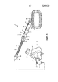
Система 2, выполненная с возможностью предоставления режима респираторной терапии пациенту в соответствии с одним из вариантов осуществления изобретения, в целом показана на ФИГ. 1. Система 2 включает в себя устройство 4 генерации давления, узел 6 подающей трубки (подробно описанный в настоящем документе) и интерфейсное устройство 8 пациента, включающее в себя угловую трубку 10, имеющую сообщение по текучей среде с узлом 6 подающей трубки.
Устройство 4 генерации давления сконструировано с возможностью генерации потока дыхательного газа и может включать в себя, без ограничения, вентиляторы, устройства поддержки постоянным давлением (такое как устройство создания непрерывного положительного давления в дыхательных путях, или устройство CPAP), устройства переменного давления (например, BiPAP®, Bi-Flex® или С-Flex™ устройства изготавливаются и распространяются Philips Respironics из Моррисвилля, штат Пенсильвания) и устройства поддержки давлением с автоматическим титрованием. Узел 6 подающей трубки сконструирован с возможностью передачи потока дыхательного газа из устройства 4 генерации давления интерфейсному устройству 8 пациента. Как более подробно описывается в настоящем документе, узел 6 подающей трубки является нагреваемым узлом подачи, который также позволяет включение в свой состав встраиваемого вспомогательного устройства 7 (такого как, без ограничения, адаптер обогащения кислородом, клапан давления, антибактериальный фильтр или любое другое подходящее вспомогательное устройство, которое можно использовать в контуре пациента устройства для респираторной терапии), схематически показанного на ФИГ. 1, на пути потока от устройства 4 генерации давления к интерфейсному устройству 8 пациента.The pressure generating
В показанном варианте осуществления, интерфейсное устройство 8 пациента является носовой/ротовой маской, сконструированной с возможностью закрывания носа и рта пациента. Однако, оставаясь в пределах объема настоящего изобретения, можно использовать любой тип интерфейсного устройства 8 пациента, который облегчает подачу потока дыхательного газа в дыхательные пути пациента и удаление потока выдыхаемого из них газа, такого как, без ограничения, носовая маска, которая закрывает нос пациента, носовые подушечки, имеющие носовые канюли, которые принимаются внутрь ноздрей пациента, или полнолицевая маска, которая закрывает лицо пациента. В варианте осуществления, показанном на ФИГ. 1, интерфейсное устройство 8 пациента включает в себя гибкую подушечку 16, жесткую или полужесткую оболочку 18 и налобный фиксатор 20. Полосы (не показаны) комплектующей детали головного убора могут прикрепляться к оболочке 18 и налобному фиксатору 20 для того, чтобы закрепить интерфейсное устройство 8 пациента на голове пациента. Отверстие в оболочке 18, к которой подсоединяется угловая трубка 10, допускает поток дыхательного газа из устройства 4 генерации давления, который должен быть передан во внутреннее пространство, определяемое оболочкой 18 и подушечкой 16, и затем, в дыхательные пути пациента. Отверстие в оболочке 18 также обеспечивает поток выдыхаемого газа (из дыхательных путей такого пациента), который должен быть передан в выпускной узел 12, предусмотренный на угловой трубке 10.In the embodiment shown, the
Как видно на ФИГ. 1, узел 6 подающей трубки включает в себя узел подогреваемой трубки 22, который напрямую сообщается по текучей среде с первым концом адаптера встраиваемого вспомогательного устройства 24. Узел 6 подающей трубки дополнительно включает в себя встраиваемое вспомогательное устройство 7. В частности, как показано на ФИГ. 1, первый конец встраиваемого вспомогательного устройства 7 напрямую сообщается по текучей среде со вторым концом адаптера 24 встраиваемого вспомогательного устройства, и второй конец встраиваемого вспомогательного устройства 7 напрямую сообщается по текучей среде с выпускным патрубком 26, допускающим подогрев трубки, устройства 4 генерации давления. Кроме того, как подробно описано ниже, адаптер 24 встраиваемого вспомогательного устройства сконструирован с возможностью обеспечения необходимого электрического соединения, которое нужно сделать между выпускным патрубком 26, допускающим подогрев трубки, и узлом 22 подогреваемой трубки, одновременно позволяя вставить встраиваемое вспомогательное устройство 7 на пути потока.As seen in FIG. 1, the
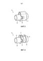
На ФИГ. 2 представлен вид в изометрии устройства 4 генерации давления в соответствии с примерным вариантом осуществления. Как видно из ФИГ. 2, устройство 4 генерации давления включает в себя основной корпус 28, в котором размещаются основные компоненты устройства 4 генерации давления (например, генератор потока (устройство вентиляции), клапан(ы), датчики, электронная аппаратура управления и т.д.). Выпускной патрубок 26 соединен с генератором потока и проходит от верхней стороны основного корпуса 28. Выпускной патрубок 26 включает в себя трубчатый патрубковый элемент 30, который в показанном варианте осуществления, представляет собой стандартный входящий в другую деталь конический штуцер по ISO, и корпус 32 патрубка, который содержит в себе электрический соединитель 34. Электрический соединитель 34 соединен с источником питания и/или другими электронными устройствами (не показано), предоставляемыми внутри основного корпуса 28. Корпус 32 патрубка дополнительно включает в себя пазовые элементы 33, назначение которых описывается в другом месте настоящего документа.In FIG. 2 is an isometric view of a
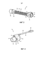
На ФИГ. 3 представлен вид в изометрии узла 22 подогреваемой трубки в соответствии с примерным вариантом осуществления. Как видно из ФИГ. 3, узел 22 подогреваемой трубки включает в себя проксимальный конец 36, дистальный конец 38 и подогреваемый шланг 40, расположенный между проксимальным концом 36 и дистальным концом 38. Дистальный конец 38 снабжен соединительным элементом 42, сконструированным с возможностью сообщения по текучей среде с угловой трубкой 10, либо непосредственно, либо через промежуточный шланг. Подогреваемый шланг 40 включает в себя центральный трубчатый элемент 44, окруженный спиральным нагревательным элементом 46. Проксимальный конец 36 снабжен соединительным элементом 48, который включает в себя трубчатый патрубковый элемент 50, который в показанном варианте осуществления является стандартным охватывающим другую деталь коническим штуцером по ISO, и корпус 52 патрубка, в котором находится электрический соединитель 54. Электрический соединитель 54 функционально соединен с нагревательным элементом 46 подогреваемого шланга 40 для подачи к ним питания и/или сигналов управления. Корпус 52 патрубка также включает в себя выступающие элементы 53, которые сконструированы с возможностью помещаться внутри пазовых элементов 33, когда встраиваемое вспомогательное устройство, как то, что описано в настоящем документе, не используется.In FIG. 3 is an isometric view of a
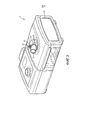
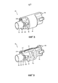
На ФИГ. 4 представлен вид в изометрии адаптера 24 встраиваемого вспомогательного устройства в соответствии с примерным вариантом осуществления. Как видно из ФИГ. 4, адаптер 24 встраиваемого вспомогательного устройства включает в себя элемент 56 соединения по текучей среде и узел 58 навесного многопроводного кабеля. Элемент 56 соединения по текучей среде сконструирован с возможностью обеспечения соединения с возможностью переноса текучей среды между проксимальным концом 36 узла 22 подогреваемой трубки и встраиваемым вспомогательным устройством 7, и узел 58 навесного многопроводного кабеля сконструирован с возможностью обеспечения электрического соединения между нагревательным элементом 46 узла подогреваемой трубки 22 и выпускным патрубком 26 устройства 4 генерации давления.In FIG. 4 is an isometric view of an
На ФИГ. 5 представлен вид в изометрии элемента 56 соединения по текучей среде адаптера встраиваемого вспомогательного устройства в соответствии с примерным вариантом осуществления. Элемент 56 соединения по текучей среде содержит центральный соединительный элемент 60, окруженный элементом 62 корпуса. На ФИГ. 6 представлен вид в изометрии центрального соединительного элемента 60 в соответствии с примерным вариантом осуществления. Как видно из ФИГ. 6, центральный соединительный элемент 60 включает в себя первый конец 64, содержащий патрубковый элемент 66, который в показанном варианте осуществления представляет собой стандартный входящий в другую деталь конический штуцер по ISO, и второй конец 68, содержащий патрубковый элемент 70, который в показанном варианте осуществления является стандартным охватывающим другую деталь коническим штуцером по ISO. Центральный соединительный элемент 60 также включает в себя корпус 72 соединителя для приема и закрепления элемента соединителя узла 58 навесного многопроводного кабеля и пазовые элементы 63 для приема и совмещения с выступающими элементами 53 узла 22 подогреваемой трубки.In FIG. 5 is an isometric view of a
На ФИГ. 7 представлен вид в изометрии узла 58 навесного многопроводного кабеля адаптера встраиваемого вспомогательного устройства в соответствии с примерным вариантом осуществления. Узел 58 навесного многопроводного кабеля включает в себя элемент 74 кабеля, содержащий несколько проводов, причем первый электрический соединитель 76 предусмотрен на первом конце элемента 74 кабеля, и второй электрический соединитель 78 предусмотрен на втором конце элемента 74 кабеля. Адаптер 24 встраиваемого вспомогательного устройства собирается путем вставки первого конца элемента 74 кабеля в элемент 62 корпуса таким образом, при котором первый электрический соединитель 76 помещается внутри корпуса соединителя 72 центрального соединительного элемента 60.In FIG. 7 is an isometric view of an
Теперь, после того, как была описана каждая из отдельных частей узла 6 подающей трубки, будет описан узел 6 подающей трубки в соответствии с примерным вариантом осуществления. Во-первых, адаптер 24 встраиваемого вспомогательного устройства соединен с проксимальным концом 36 узла подогреваемой трубки 22. Более конкретно, патрубковый элемент 66 адаптера 24 встраиваемого вспомогательного устройства соединен с трубчатым патрубковым элементом 50 узла 22 подогреваемой трубки и выступающие элементы 53 вставлены в пазовые элементы 63. Кроме того, электрический соединитель 54 узла 22 подогреваемой трубки соединен с первым электрическим соединителем 76, предусмотренным на первом конце элемента 74 кабеля адаптера 24 встраиваемого вспомогательного устройства. Далее, первый конец встраиваемого вспомогательного устройства 7 сообщается по текучей среде с патрубковым элементом 70 адаптера 24 встраиваемого вспомогательного устройства. В не ограничивающем примерном варианте осуществления, встраиваемое вспомогательное устройство 7 имеет штуцер 9 с охватываемым концом 9, который соединен с патрубковым элементом 70. Дальше второй конец встраиваемого вспомогательного устройства 7 сообщается по текучей среде с трубчатым патрубковым элементом 30 выпускного патрубка 26. В не ограничивающем примерном варианте осуществления, встраиваемое вспомогательное устройство 7 имеет штуцер 11 с охватывающим концом, который соединен с трубчатым патрубковым элементом 30. Как будет понятно, это ведет к тому, что узел 22 подогреваемой трубки сообщается по текучей среде с выпускным патрубком 26 устройства 4 генерации давления через адаптер 24 встраиваемого вспомогательного устройства. Наконец второй электрический соединитель 78, предусмотренный на втором конце элемента 74 кабеля адаптера 24 встраиваемого вспомогательного устройства, соединен с электрическим соединителем 34 выпускного патрубка 26. Как будет понятно, это ведет к тому, что нагревательный элемент 46 узла 22 подогреваемой трубки электрически подсоединяется к выпускному 26 патрубку устройства 4 генерации давления (и таким образом электропитанию устройства 4 генерации давления) через адаптер 24 встраиваемого вспомогательного устройства.Now, after each of the individual parts of the
Таким образом, адаптер 24 встраиваемого вспомогательного устройства, как только что описанный, обеспечивает простой в использовании механизм для обеспечения необходимого электрического соединения, которое нужно сделать между выпускным патрубком 26, допускающим подогрев трубки, и узлом 22 подогреваемой трубки, одновременно позволяя вставить встраиваемое вспомогательное устройство 7 на пути потока к пользователю.Thus, the
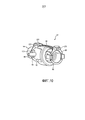
На ФИГ. 8 представлен вид в изометрии адаптера 80 обогащения с альтернативным примерным вариантом осуществления настоящего изобретения. Адаптером 80 обогащения можно заменить адаптер 24 встраиваемого вспомогательного устройства и встраиваемое вспомогательное устройство 7 в узле 6 подающей трубки, показанной на ФИГ. 1, для того, чтобы дать возможность кислороду или другому добавочному газу, быть добавленным в путь потока к интерфейсному устройству 8 пациента, в то же время делая возможным создание электрического соединения с узлом 22 подогреваемой трубки из выпускного патрубка 26.In FIG. 8 is a perspective view of an
Адаптер 80 обогащения включает в себя центральный узел 82 адаптера, окруженный элементом 84 корпуса. На ФИГ. 9 и 10 представлены соответственно изометрические виды спереди и сзади центрального узла 82 адаптера в соответствии с примерным вариантом осуществления. Как видно из ФИГ. 9 и 10, центральный узел 82 адаптера включает в себя первый конец 84, второй конец 86 и узел 98 навесного многопроводного кабеля. Второй конец 86 аналогичен по структуре проксимальному концу 36 узла 22 подогреваемой трубки и включает в себя патрубковый элемент 88 (который в показанном варианте осуществления является стандартным охватывающим другую деталь коническим штуцером по ISO) и выступающие элементы 89, сконструированные с возможностью совмещения с пазовыми элементами 33 выпускного патрубка 26. Как видно из ФИГ. 9 и 10 и как описано более подробно ниже, второй конец 86 сконструирован с возможностью закрепления первого электрического соединителя 100 узла 98 навесного многопроводного кабеля с тем, чтобы дать возможность соединить второй конец 86 с выпускным патрубком 26 устройства 4 генерации давления по текучей среде и электрически. Первый конец 84 включает в себя соединительный элемент 92, который содержит элемент 94 присоединительного патрубка, который в показанном варианте осуществления является стандартным входящим в другую деталь коническим штуцером по ISO, выпускной патрубок 96 для газа, обеспечивающий доступ к внутренней камере, определяемой соединительным элементом 92, для того, чтобы дать возможность ввести добавочный газ, такой как кислород, в путь потока к интерфейсному устройству 8 пациента, корпус 102 соединителя для приема и закрепления второго соединительного элемента 104 узла 98 навесного многопроводного кабеля, и пазовые элементы 103, сконструированные с возможностью совмещения с выступающими элементами 53 узла подогреваемой трубки. Таким образом, первый конец 84 сконструирован с возможностью сообщения по текучей среде и электрически с проксимальным концом 36 узла подогреваемой трубки 22. Второй конец 86 в показанном примерном варианте осуществления дополнительно включает в себя клапан 106, предотвращающий обратный поток, сконструированный с возможностью предотвращения обратного потока дополнительного газа в устройство 4 генерации давления, когда устройство 4 генерации давления не работает.The
Таким образом, адаптер 80 обогащения, как только что описанный, является устройством, которое можно вставить между узлом 22 подогреваемой трубки и выпускным патрубком 26, который, будучи так вставлен, одновременно обеспечивает (i) основной путь потока текучей среды из устройства 4 генерации давления узла 22 подогреваемой трубки, (ii) вспомогательный путь, по которому добавочный газ может быть введен в главный путь потока, и (iii) электрическое подсоединение к узлу 22 подогреваемой трубки из выпускного патрубка 26 посредством перемычки в виде узла 98 навесного многопроводного кабеля.Thus, the
Кроме того, в то время как в показанных вариантах осуществления адаптер 24 встраиваемого вспомогательного устройства и адаптер 80 обогащения описаны в качестве используемых с узлом 22 подогреваемой трубки, должно быть понятно, что настоящее изобретение не ограничивается использованием только подогреваемых трубок. Предпочтительно, адаптер 24 встраиваемого вспомогательного устройства и адаптер 80 обогащения можно использовать с любым типом узла электрической трубки, к которому должно быть сделано электрическое подключение, таким как, без ограничения, узлом электрической трубки, который включает в себя один или несколько проводов для проведения электрического сигнала от интерфейсного устройства пациента к базовому блоку и/или от базового блока к интерфейсному устройству пациента.In addition, while in the shown embodiments, the embedded
В формуле изобретения, любые ссылочные позиции, размещенные в скобках, не следует толковать, как ограничивающее требование. Слово «содержит» или «включает в себя» не исключает наличия элементов или этапов, отличных от тех, что перечислены в пункте формулы изобретения. В пункте формулы изобретения на устройство, в котором перечислено несколько средств, несколько из этих средств могут быть осуществлены посредством одного и того же элемента аппаратного обеспечения. Указание элемента в единственном числе не исключает присутствия множества таких элементов. В любом пункте формулы изобретения на устройство, в котором перечислено несколько средств, несколько из этих средств могут быть осуществлены посредством одного и того же элемента аппаратного обеспечения. Тот факт, что определенные элементы перечислены во взаимно отличных зависимых пунктах формулы изобретения, не указывает на то, что эти элементы не могут использоваться в сочетании.In the claims, any reference numerals in parentheses should not be construed as limiting. The word “comprises” or “includes” does not exclude the presence of elements or steps other than those listed in a claim. In a claim on a device in which several means are listed, several of these means can be implemented by the same hardware element. Indication of an element in the singular does not exclude the presence of a plurality of such elements. At any point in the claims on a device in which several means are listed, several of these means may be implemented by the same hardware element. The fact that certain elements are listed in mutually different dependent dependent claims does not indicate that these elements cannot be used in combination.
Хотя изобретение было описано подробно с целью иллюстрации, основанное на том, что в настоящее время считается наиболее практичными и предпочтительными вариантами осуществления, следует понимать, что такие подробности приводятся исключительно для этой цели и что изобретение не ограничивается описанными вариантами осуществления, но, напротив, предназначен для охвата модификаций и эквивалентных компоновок, которые находятся в пределах сущности и объема прилагаемой формулы изобретения. Например, следует понимать, что настоящее изобретение предполагает, что, по мере возможности, один или несколько признаков любого варианта осуществления могут быть объединены с одним или несколькими признаками любого другого варианта осуществления.Although the invention has been described in detail for the purpose of illustration, based on what is currently considered the most practical and preferred embodiments, it should be understood that such details are provided solely for this purpose and that the invention is not limited to the described embodiments, but, on the contrary, is intended to cover modifications and equivalent arrangements that fall within the spirit and scope of the appended claims. For example, it should be understood that the present invention contemplates that, as far as possible, one or more features of any embodiment may be combined with one or more features of any other embodiment.
Claims (15)
Applications Claiming Priority (3)
| Application Number | Priority Date | Filing Date | Title |
|---|---|---|---|
| US201261740217P | 2012-12-20 | 2012-12-20 | |
| US61/740,217 | 2012-12-20 | ||
| PCT/IB2013/061037 WO2014097145A1 (en) | 2012-12-20 | 2013-12-17 | Inline adapter for a respiratory therapy device |
Publications (2)
| Publication Number | Publication Date |
|---|---|
| RU2015129059A RU2015129059A (en) | 2017-01-26 |
| RU2657953C2 true RU2657953C2 (en) | 2018-06-18 |
Family
ID=50001064
Family Applications (1)
| Application Number | Title | Priority Date | Filing Date |
|---|---|---|---|
| RU2015129059A RU2657953C2 (en) | 2012-12-20 | 2013-12-17 | Inline adapter for respiratory therapy device |
Country Status (8)
| Country | Link |
|---|---|
| US (1) | US9974917B2 (en) |
| EP (2) | EP3034122B1 (en) |
| JP (1) | JP6378199B2 (en) |
| CN (1) | CN104870042B (en) |
| AU (1) | AU2013365825B2 (en) |
| BR (1) | BR112015014324B1 (en) |
| RU (1) | RU2657953C2 (en) |
| WO (1) | WO2014097145A1 (en) |
Families Citing this family (39)
| Publication number | Priority date | Publication date | Assignee | Title |
|---|---|---|---|---|
| ES2644926T3 (en) | 2011-08-10 | 2017-12-01 | Fisher&Paykel Healthcare Limited | Duct connector for a patient breathing device |
| USD747471S1 (en) | 2012-08-10 | 2016-01-12 | Fisher & Paykel Healthcare Limited | Connector |
| USD738488S1 (en) | 2013-05-31 | 2015-09-08 | Resmed Limited | Positive airway pressure delivery console |
| USD738489S1 (en) | 2013-05-31 | 2015-09-08 | Resmed Limited | Positive airway pressure delivery console |
| USD743556S1 (en) | 2014-02-19 | 2015-11-17 | Resmed Limited | Positive airway pressure delivery console |
| JP1525591S (en) | 2014-02-19 | 2018-05-21 | ||
| USD762843S1 (en) * | 2014-03-18 | 2016-08-02 | Resmed Limited | Air delivery tube |
| USD760258S1 (en) | 2014-05-30 | 2016-06-28 | Resmed Limited | Display screen with graphical user interface |
| CN117414515A (en) * | 2014-07-07 | 2024-01-19 | 费雪派克医疗保健有限公司 | Medical tube and connector for gas delivery system |
| USD809124S1 (en) | 2014-09-12 | 2018-01-30 | Resmed Limited | Pressurized air delivery console |
| USD790683S1 (en) | 2015-03-11 | 2017-06-27 | Resmed Limited | Pressurized air delivery console |
| CN112891694A (en) * | 2015-03-31 | 2021-06-04 | 费雪派克医疗保健有限公司 | Apparatus for use in a respiratory support system |
| CN113069659A (en) | 2015-09-04 | 2021-07-06 | 费雪派克医疗保健有限公司 | Catheter connector |
| USD807995S1 (en) | 2015-09-22 | 2018-01-16 | Fisher & Paykel Healthcare Limited | Circuit kit for a humidifier |
| USD841147S1 (en) * | 2015-09-30 | 2019-02-19 | Fisher & Paykel Healthcare Limited | Circuit kit for a humidifier |
| USD805630S1 (en) | 2016-02-02 | 2017-12-19 | Resmed Limited | Air delivery tube |
| USD809656S1 (en) | 2016-06-10 | 2018-02-06 | Fisher & Paykel Healthcare Limited | Connector for a breathing circuit |
| USD841148S1 (en) * | 2016-07-21 | 2019-02-19 | Fisher & Paykel Healthcare Limited | Breathing tube |
| US10953185B2 (en) * | 2017-03-31 | 2021-03-23 | Koninklijke Philips N.V. | Moisture wicking conduit and system |
| USD895788S1 (en) * | 2018-01-30 | 2020-09-08 | Inovytec Medical Solutions Ltd. | Patient circuit for gas delivery |
| US20190290880A1 (en) * | 2018-03-20 | 2019-09-26 | Ideya Labs, LLC | Positive airway pressure oil delivery system |
| DE102018126886A1 (en) * | 2018-10-19 | 2020-04-23 | Eugen Forschner Gmbh | Connection arrangement |
| US20220023576A1 (en) * | 2018-11-05 | 2022-01-27 | Fisher & Paykel Healthcare Limited | Breathing assistance apparatus and/or components thereof |
| JP6979148B1 (en) * | 2018-11-16 | 2021-12-08 | コーニンクレッカ フィリップス エヌ ヴェKoninklijke Philips N.V. | Pressure support system valve |
| USD921900S1 (en) | 2018-12-19 | 2021-06-08 | ResMed Pty Ltd | Humidification tub |
| US20220355059A1 (en) * | 2019-07-08 | 2022-11-10 | Fisher & Paykel Healthcare Limited | Medical tubes and connectors for breathing circuits |
| US10737049B1 (en) * | 2019-08-05 | 2020-08-11 | Dynasthetics, Llc | Apparatus for connecting oxygen delivery control instrument to patient delivery device |
| USD1006981S1 (en) | 2019-09-06 | 2023-12-05 | Fisher & Paykel Healthcare Limited | Breathing conduit |
| USD948027S1 (en) | 2019-09-10 | 2022-04-05 | Fisher & Paykel Healthcare Limited | Connector for a breathing conduit |
| EP4051351A1 (en) * | 2019-10-31 | 2022-09-07 | ResMed Sensor Technologies Limited | Systems and methods for injecting substances into a respiratory system |
| USD944939S1 (en) * | 2020-02-26 | 2022-03-01 | Soclean, Inc. | Connector for a sanitizing machine |
| USD957589S1 (en) * | 2020-02-26 | 2022-07-12 | Soclean, Inc. | Connector for a sanitizing machine |
| USD949295S1 (en) * | 2020-02-26 | 2022-04-19 | Soclean Inc. | Connector for a sanitizing machine |
| USD944938S1 (en) * | 2020-02-26 | 2022-03-01 | Soclean, Inc. | Connector for a sanitizing machine |
| USD944941S1 (en) * | 2020-02-27 | 2022-03-01 | Soclean, Inc. | Connector for a sanitizing machine |
| USD940861S1 (en) | 2020-03-03 | 2022-01-11 | Fisher & Paykel Healthcare Limited | Connector for a respiratory system conduit |
| AU2021376441A1 (en) * | 2020-11-03 | 2023-06-22 | ResMed Pty Ltd | Respiratory pressure therapy device |
| USD974551S1 (en) | 2020-12-09 | 2023-01-03 | Fisher & Paykel Healthcare Limited | Connector assembly and connector |
| USD995758S1 (en) | 2021-06-11 | 2023-08-15 | Fisher & Paykel Healthcare Limited | Tube assembly and connector |
Citations (8)
| Publication number | Priority date | Publication date | Assignee | Title |
|---|---|---|---|---|
| EP1127583A2 (en) * | 2000-02-24 | 2001-08-29 | Siemens-Elema AB | Conduit with transmission line |
| DE19958296C1 (en) * | 1999-12-03 | 2001-09-20 | Map Gmbh | Heated breathing tube for patient has heating element formed by tube wall and consisting of layer of electrically conductive synthetic material, voltage supply line integrated into tube wall |
| RU2001110752A (en) * | 2001-04-24 | 2003-03-10 | Александр Андреевич Панин | METHOD FOR FORMING AND SUBMITTING A RESPIRATORY ENVIRONMENT AND APPARATUS FOR ITS IMPLEMENTATION |
| US20030059213A1 (en) * | 2000-03-21 | 2003-03-27 | Mackie Scott Robert | Gases delivery conduit |
| WO2008076230A2 (en) * | 2006-12-14 | 2008-06-26 | Mergenet Medical Inc. | High flow therapy device utilizing a non-sealing respiratory interface and related methods |
| WO2008105257A1 (en) * | 2007-02-26 | 2008-09-04 | Nec Corporation | High-frequency circuit |
| WO2009022004A2 (en) * | 2007-08-14 | 2009-02-19 | Plastiflex Belgium | A respiratory system |
| WO2012160477A1 (en) * | 2011-05-20 | 2012-11-29 | Koninklijke Philips Electronics N.V. | Rotating electrical connector and respiratory gas delivery system employing same |
Family Cites Families (14)
| Publication number | Priority date | Publication date | Assignee | Title |
|---|---|---|---|---|
| JPH08317983A (en) * | 1995-03-17 | 1996-12-03 | Teijin Ltd | Aspirating gas supplying apparatus |
| EP1011773A4 (en) * | 1997-08-14 | 2002-02-20 | Resmed Ltd | An apparatus and method for supplying on-demand additional breathable gas |
| SE9704663D0 (en) * | 1997-12-15 | 1997-12-15 | Siemens Elema Ab | Fan system |
| DE10134725A1 (en) * | 2001-07-17 | 2003-02-06 | Weinmann G Geraete Med | Device for filtering breathing air |
| DE102005000922A1 (en) * | 2005-01-07 | 2006-07-20 | Seleon Gmbh | Aerial goggles, nosepiece, Y-piece and procedures |
| CN101365509A (en) * | 2005-12-14 | 2009-02-11 | 莫哲奈特医疗公司 | High flow therapy device |
| EP4176915A1 (en) * | 2006-11-08 | 2023-05-10 | ResMed Pty Ltd | Respiratory apparatus |
| NZ575837A (en) * | 2006-11-08 | 2012-07-27 | Resmed Ltd | Conduit for heating a breathable gas in a respiratory apparatus |
| US8770198B2 (en) | 2006-12-21 | 2014-07-08 | Resmed Limited | Connector |
| CN102196837B (en) | 2008-08-22 | 2015-09-09 | 呼吸科技公司 | Open air flue interface is utilized to provide the method and apparatus of mechanical ventilation |
| AU2010206053B2 (en) * | 2009-07-31 | 2014-08-07 | ResMed Pty Ltd | Wire Heated Tube with Temperature Control System, Tube Type Detection, and Active Over Temperature Protection for Humidifier for Respiratory Apparatus |
| NZ716696A (en) * | 2010-09-06 | 2017-08-25 | Resmed Ltd | Methods and apparatus for preventing rainout |
| KR102160009B1 (en) * | 2011-07-15 | 2020-09-25 | 소클린, 인크. | Systems, methods and devices for ozone sanitization of continuous positive airway pressure devices |
| EP2833954B1 (en) | 2012-04-05 | 2020-06-03 | Fisher&Paykel Healthcare Limited | Breathing assistance apparatus with serviceability features |
-
2013
- 2013-12-17 CN CN201380067180.9A patent/CN104870042B/en active Active
- 2013-12-17 EP EP15200001.4A patent/EP3034122B1/en active Active
- 2013-12-17 WO PCT/IB2013/061037 patent/WO2014097145A1/en active Application Filing
- 2013-12-17 US US14/646,740 patent/US9974917B2/en active Active
- 2013-12-17 RU RU2015129059A patent/RU2657953C2/en active
- 2013-12-17 AU AU2013365825A patent/AU2013365825B2/en active Active
- 2013-12-17 EP EP13824204.5A patent/EP2934644B1/en active Active
- 2013-12-17 BR BR112015014324-5A patent/BR112015014324B1/en active IP Right Grant
- 2013-12-17 JP JP2015548835A patent/JP6378199B2/en active Active
Patent Citations (8)
| Publication number | Priority date | Publication date | Assignee | Title |
|---|---|---|---|---|
| DE19958296C1 (en) * | 1999-12-03 | 2001-09-20 | Map Gmbh | Heated breathing tube for patient has heating element formed by tube wall and consisting of layer of electrically conductive synthetic material, voltage supply line integrated into tube wall |
| EP1127583A2 (en) * | 2000-02-24 | 2001-08-29 | Siemens-Elema AB | Conduit with transmission line |
| US20030059213A1 (en) * | 2000-03-21 | 2003-03-27 | Mackie Scott Robert | Gases delivery conduit |
| RU2001110752A (en) * | 2001-04-24 | 2003-03-10 | Александр Андреевич Панин | METHOD FOR FORMING AND SUBMITTING A RESPIRATORY ENVIRONMENT AND APPARATUS FOR ITS IMPLEMENTATION |
| WO2008076230A2 (en) * | 2006-12-14 | 2008-06-26 | Mergenet Medical Inc. | High flow therapy device utilizing a non-sealing respiratory interface and related methods |
| WO2008105257A1 (en) * | 2007-02-26 | 2008-09-04 | Nec Corporation | High-frequency circuit |
| WO2009022004A2 (en) * | 2007-08-14 | 2009-02-19 | Plastiflex Belgium | A respiratory system |
| WO2012160477A1 (en) * | 2011-05-20 | 2012-11-29 | Koninklijke Philips Electronics N.V. | Rotating electrical connector and respiratory gas delivery system employing same |
Also Published As
| Publication number | Publication date |
|---|---|
| JP6378199B2 (en) | 2018-08-22 |
| CN104870042A (en) | 2015-08-26 |
| EP3034122A1 (en) | 2016-06-22 |
| WO2014097145A1 (en) | 2014-06-26 |
| US9974917B2 (en) | 2018-05-22 |
| AU2013365825B2 (en) | 2018-07-12 |
| RU2015129059A (en) | 2017-01-26 |
| EP2934644A1 (en) | 2015-10-28 |
| EP3034122B1 (en) | 2020-09-16 |
| EP2934644B1 (en) | 2019-02-27 |
| BR112015014324A2 (en) | 2017-07-11 |
| US20150306332A1 (en) | 2015-10-29 |
| CN104870042B (en) | 2019-01-22 |
| BR112015014324B1 (en) | 2021-05-18 |
| AU2013365825A1 (en) | 2015-08-06 |
| JP2016501608A (en) | 2016-01-21 |
Similar Documents
| Publication | Publication Date | Title |
|---|---|---|
| RU2657953C2 (en) | Inline adapter for respiratory therapy device | |
| JP6878643B2 (en) | Outlet connection assembly and how to form the assembly | |
| CN104853796B (en) | Rotating fluid connector | |
| US9717873B2 (en) | Rotating electrical connector ADN respiratory gas delivery system employing same | |
| CA2556016C (en) | Sealing nasal cannula | |
| US11090456B2 (en) | Liquid removal in a patient interface assembly | |
| JP2014532500A (en) | Modular patient interface device with chamber and nasal pillow assembly | |
| US20130220328A1 (en) | Gas delivery conduit management system | |
| CN110944704B (en) | Respiratory user interface | |
| US10369316B2 (en) | Forhead gas supply assembly for a patient interface system | |
| US20160206844A1 (en) | Releasable elbow connector | |
| CN213554576U (en) | Oxygen inhalation nasal plug device | |
| TW202412872A (en) | Medical tube |