EP2934644B1 - Inline adapter for a respiratory therapy device - Google Patents
Inline adapter for a respiratory therapy device Download PDFInfo
- Publication number
- EP2934644B1 EP2934644B1 EP13824204.5A EP13824204A EP2934644B1 EP 2934644 B1 EP2934644 B1 EP 2934644B1 EP 13824204 A EP13824204 A EP 13824204A EP 2934644 B1 EP2934644 B1 EP 2934644B1
- Authority
- EP
- European Patent Office
- Prior art keywords
- pressure generating
- tube assembly
- generating device
- structured
- electrical
- Prior art date
- Legal status (The legal status is an assumption and is not a legal conclusion. Google has not performed a legal analysis and makes no representation as to the accuracy of the status listed.)
- Active
Links
- 238000002644 respiratory therapy Methods 0.000 title claims description 10
- 239000007789 gas Substances 0.000 claims description 22
- 230000008878 coupling Effects 0.000 claims description 21
- 238000010168 coupling process Methods 0.000 claims description 21
- 238000005859 coupling reaction Methods 0.000 claims description 21
- 239000012530 fluid Substances 0.000 claims description 17
- 230000029058 respiratory gaseous exchange Effects 0.000 claims description 15
- QVGXLLKOCUKJST-UHFFFAOYSA-N atomic oxygen Chemical compound [O] QVGXLLKOCUKJST-UHFFFAOYSA-N 0.000 claims description 8
- 239000001301 oxygen Substances 0.000 claims description 8
- 229910052760 oxygen Inorganic materials 0.000 claims description 8
- 241000894006 Bacteria Species 0.000 claims description 3
- 238000002560 therapeutic procedure Methods 0.000 description 8
- 230000000052 comparative effect Effects 0.000 description 6
- 230000000153 supplemental effect Effects 0.000 description 6
- 238000010438 heat treatment Methods 0.000 description 4
- 230000013011 mating Effects 0.000 description 4
- 210000001061 forehead Anatomy 0.000 description 3
- 238000009423 ventilation Methods 0.000 description 3
- 238000004891 communication Methods 0.000 description 2
- 210000003128 head Anatomy 0.000 description 2
- 238000000034 method Methods 0.000 description 2
- 230000000241 respiratory effect Effects 0.000 description 2
- 210000002345 respiratory system Anatomy 0.000 description 2
- 230000005540 biological transmission Effects 0.000 description 1
- 230000003247 decreasing effect Effects 0.000 description 1
- 230000001419 dependent effect Effects 0.000 description 1
- 238000010586 diagram Methods 0.000 description 1
- 210000003238 esophagus Anatomy 0.000 description 1
- 238000004519 manufacturing process Methods 0.000 description 1
- 238000012986 modification Methods 0.000 description 1
- 230000004048 modification Effects 0.000 description 1
- 230000002265 prevention Effects 0.000 description 1
- 238000007789 sealing Methods 0.000 description 1
- 230000008054 signal transmission Effects 0.000 description 1
- 238000004448 titration Methods 0.000 description 1
Images

Classifications
-
- A—HUMAN NECESSITIES
- A61—MEDICAL OR VETERINARY SCIENCE; HYGIENE
- A61M—DEVICES FOR INTRODUCING MEDIA INTO, OR ONTO, THE BODY; DEVICES FOR TRANSDUCING BODY MEDIA OR FOR TAKING MEDIA FROM THE BODY; DEVICES FOR PRODUCING OR ENDING SLEEP OR STUPOR
- A61M16/00—Devices for influencing the respiratory system of patients by gas treatment, e.g. mouth-to-mouth respiration; Tracheal tubes
- A61M16/08—Bellows; Connecting tubes ; Water traps; Patient circuits
- A61M16/0816—Joints or connectors
-
- A—HUMAN NECESSITIES
- A61—MEDICAL OR VETERINARY SCIENCE; HYGIENE
- A61M—DEVICES FOR INTRODUCING MEDIA INTO, OR ONTO, THE BODY; DEVICES FOR TRANSDUCING BODY MEDIA OR FOR TAKING MEDIA FROM THE BODY; DEVICES FOR PRODUCING OR ENDING SLEEP OR STUPOR
- A61M16/00—Devices for influencing the respiratory system of patients by gas treatment, e.g. mouth-to-mouth respiration; Tracheal tubes
- A61M16/0057—Pumps therefor
-
- A—HUMAN NECESSITIES
- A61—MEDICAL OR VETERINARY SCIENCE; HYGIENE
- A61M—DEVICES FOR INTRODUCING MEDIA INTO, OR ONTO, THE BODY; DEVICES FOR TRANSDUCING BODY MEDIA OR FOR TAKING MEDIA FROM THE BODY; DEVICES FOR PRODUCING OR ENDING SLEEP OR STUPOR
- A61M15/00—Inhalators
- A61M15/08—Inhaling devices inserted into the nose
-
- A—HUMAN NECESSITIES
- A61—MEDICAL OR VETERINARY SCIENCE; HYGIENE
- A61M—DEVICES FOR INTRODUCING MEDIA INTO, OR ONTO, THE BODY; DEVICES FOR TRANSDUCING BODY MEDIA OR FOR TAKING MEDIA FROM THE BODY; DEVICES FOR PRODUCING OR ENDING SLEEP OR STUPOR
- A61M16/00—Devices for influencing the respiratory system of patients by gas treatment, e.g. mouth-to-mouth respiration; Tracheal tubes
- A61M16/06—Respiratory or anaesthetic masks
- A61M16/0666—Nasal cannulas or tubing
-
- A—HUMAN NECESSITIES
- A61—MEDICAL OR VETERINARY SCIENCE; HYGIENE
- A61M—DEVICES FOR INTRODUCING MEDIA INTO, OR ONTO, THE BODY; DEVICES FOR TRANSDUCING BODY MEDIA OR FOR TAKING MEDIA FROM THE BODY; DEVICES FOR PRODUCING OR ENDING SLEEP OR STUPOR
- A61M16/00—Devices for influencing the respiratory system of patients by gas treatment, e.g. mouth-to-mouth respiration; Tracheal tubes
- A61M16/08—Bellows; Connecting tubes ; Water traps; Patient circuits
- A61M16/0816—Joints or connectors
- A61M16/0833—T- or Y-type connectors, e.g. Y-piece
-
- A—HUMAN NECESSITIES
- A61—MEDICAL OR VETERINARY SCIENCE; HYGIENE
- A61M—DEVICES FOR INTRODUCING MEDIA INTO, OR ONTO, THE BODY; DEVICES FOR TRANSDUCING BODY MEDIA OR FOR TAKING MEDIA FROM THE BODY; DEVICES FOR PRODUCING OR ENDING SLEEP OR STUPOR
- A61M16/00—Devices for influencing the respiratory system of patients by gas treatment, e.g. mouth-to-mouth respiration; Tracheal tubes
- A61M16/08—Bellows; Connecting tubes ; Water traps; Patient circuits
- A61M16/0875—Connecting tubes
-
- A—HUMAN NECESSITIES
- A61—MEDICAL OR VETERINARY SCIENCE; HYGIENE
- A61M—DEVICES FOR INTRODUCING MEDIA INTO, OR ONTO, THE BODY; DEVICES FOR TRANSDUCING BODY MEDIA OR FOR TAKING MEDIA FROM THE BODY; DEVICES FOR PRODUCING OR ENDING SLEEP OR STUPOR
- A61M16/00—Devices for influencing the respiratory system of patients by gas treatment, e.g. mouth-to-mouth respiration; Tracheal tubes
- A61M16/10—Preparation of respiratory gases or vapours
- A61M16/1075—Preparation of respiratory gases or vapours by influencing the temperature
- A61M16/1095—Preparation of respiratory gases or vapours by influencing the temperature in the connecting tubes
-
- A—HUMAN NECESSITIES
- A61—MEDICAL OR VETERINARY SCIENCE; HYGIENE
- A61M—DEVICES FOR INTRODUCING MEDIA INTO, OR ONTO, THE BODY; DEVICES FOR TRANSDUCING BODY MEDIA OR FOR TAKING MEDIA FROM THE BODY; DEVICES FOR PRODUCING OR ENDING SLEEP OR STUPOR
- A61M16/00—Devices for influencing the respiratory system of patients by gas treatment, e.g. mouth-to-mouth respiration; Tracheal tubes
- A61M16/0057—Pumps therefor
- A61M16/0066—Blowers or centrifugal pumps
-
- A—HUMAN NECESSITIES
- A61—MEDICAL OR VETERINARY SCIENCE; HYGIENE
- A61M—DEVICES FOR INTRODUCING MEDIA INTO, OR ONTO, THE BODY; DEVICES FOR TRANSDUCING BODY MEDIA OR FOR TAKING MEDIA FROM THE BODY; DEVICES FOR PRODUCING OR ENDING SLEEP OR STUPOR
- A61M16/00—Devices for influencing the respiratory system of patients by gas treatment, e.g. mouth-to-mouth respiration; Tracheal tubes
- A61M16/06—Respiratory or anaesthetic masks
-
- A—HUMAN NECESSITIES
- A61—MEDICAL OR VETERINARY SCIENCE; HYGIENE
- A61M—DEVICES FOR INTRODUCING MEDIA INTO, OR ONTO, THE BODY; DEVICES FOR TRANSDUCING BODY MEDIA OR FOR TAKING MEDIA FROM THE BODY; DEVICES FOR PRODUCING OR ENDING SLEEP OR STUPOR
- A61M16/00—Devices for influencing the respiratory system of patients by gas treatment, e.g. mouth-to-mouth respiration; Tracheal tubes
- A61M16/10—Preparation of respiratory gases or vapours
- A61M16/105—Filters
- A61M16/1055—Filters bacterial
-
- A—HUMAN NECESSITIES
- A61—MEDICAL OR VETERINARY SCIENCE; HYGIENE
- A61M—DEVICES FOR INTRODUCING MEDIA INTO, OR ONTO, THE BODY; DEVICES FOR TRANSDUCING BODY MEDIA OR FOR TAKING MEDIA FROM THE BODY; DEVICES FOR PRODUCING OR ENDING SLEEP OR STUPOR
- A61M16/00—Devices for influencing the respiratory system of patients by gas treatment, e.g. mouth-to-mouth respiration; Tracheal tubes
- A61M16/10—Preparation of respiratory gases or vapours
- A61M16/12—Preparation of respiratory gases or vapours by mixing different gases
-
- A—HUMAN NECESSITIES
- A61—MEDICAL OR VETERINARY SCIENCE; HYGIENE
- A61M—DEVICES FOR INTRODUCING MEDIA INTO, OR ONTO, THE BODY; DEVICES FOR TRANSDUCING BODY MEDIA OR FOR TAKING MEDIA FROM THE BODY; DEVICES FOR PRODUCING OR ENDING SLEEP OR STUPOR
- A61M16/00—Devices for influencing the respiratory system of patients by gas treatment, e.g. mouth-to-mouth respiration; Tracheal tubes
- A61M16/20—Valves specially adapted to medical respiratory devices
- A61M16/208—Non-controlled one-way valves, e.g. exhalation, check, pop-off non-rebreathing valves
-
- A—HUMAN NECESSITIES
- A61—MEDICAL OR VETERINARY SCIENCE; HYGIENE
- A61M—DEVICES FOR INTRODUCING MEDIA INTO, OR ONTO, THE BODY; DEVICES FOR TRANSDUCING BODY MEDIA OR FOR TAKING MEDIA FROM THE BODY; DEVICES FOR PRODUCING OR ENDING SLEEP OR STUPOR
- A61M39/00—Tubes, tube connectors, tube couplings, valves, access sites or the like, specially adapted for medical use
- A61M39/10—Tube connectors; Tube couplings
- A61M2039/1022—Tube connectors; Tube couplings additionally providing electrical connection
-
- A—HUMAN NECESSITIES
- A61—MEDICAL OR VETERINARY SCIENCE; HYGIENE
- A61M—DEVICES FOR INTRODUCING MEDIA INTO, OR ONTO, THE BODY; DEVICES FOR TRANSDUCING BODY MEDIA OR FOR TAKING MEDIA FROM THE BODY; DEVICES FOR PRODUCING OR ENDING SLEEP OR STUPOR
- A61M2202/00—Special media to be introduced, removed or treated
- A61M2202/02—Gases
- A61M2202/0208—Oxygen
-
- A—HUMAN NECESSITIES
- A61—MEDICAL OR VETERINARY SCIENCE; HYGIENE
- A61M—DEVICES FOR INTRODUCING MEDIA INTO, OR ONTO, THE BODY; DEVICES FOR TRANSDUCING BODY MEDIA OR FOR TAKING MEDIA FROM THE BODY; DEVICES FOR PRODUCING OR ENDING SLEEP OR STUPOR
- A61M2205/00—General characteristics of the apparatus
- A61M2205/36—General characteristics of the apparatus related to heating or cooling
-
- A—HUMAN NECESSITIES
- A61—MEDICAL OR VETERINARY SCIENCE; HYGIENE
- A61M—DEVICES FOR INTRODUCING MEDIA INTO, OR ONTO, THE BODY; DEVICES FOR TRANSDUCING BODY MEDIA OR FOR TAKING MEDIA FROM THE BODY; DEVICES FOR PRODUCING OR ENDING SLEEP OR STUPOR
- A61M2205/00—General characteristics of the apparatus
- A61M2205/50—General characteristics of the apparatus with microprocessors or computers
-
- A—HUMAN NECESSITIES
- A61—MEDICAL OR VETERINARY SCIENCE; HYGIENE
- A61M—DEVICES FOR INTRODUCING MEDIA INTO, OR ONTO, THE BODY; DEVICES FOR TRANSDUCING BODY MEDIA OR FOR TAKING MEDIA FROM THE BODY; DEVICES FOR PRODUCING OR ENDING SLEEP OR STUPOR
- A61M2205/00—General characteristics of the apparatus
- A61M2205/75—General characteristics of the apparatus with filters
- A61M2205/7518—General characteristics of the apparatus with filters bacterial
-
- A—HUMAN NECESSITIES
- A61—MEDICAL OR VETERINARY SCIENCE; HYGIENE
- A61M—DEVICES FOR INTRODUCING MEDIA INTO, OR ONTO, THE BODY; DEVICES FOR TRANSDUCING BODY MEDIA OR FOR TAKING MEDIA FROM THE BODY; DEVICES FOR PRODUCING OR ENDING SLEEP OR STUPOR
- A61M2210/00—Anatomical parts of the body
- A61M2210/10—Trunk
- A61M2210/1042—Alimentary tract
- A61M2210/1046—Pharynx
Definitions
- the present invention pertains to systems for treating conditions, such as sleep disordered breathing, using positive airway pressure (PAP) therapy, and, in particular, to an inline adapter for a pressure support device that also allows for an electrical connection to be made between electrical (e.g., heated tubing) and the pressure support device.
- PAP positive airway pressure
- CPAP continuous positive airway pressure
- variable airway pressure wherein the pressure provided to the airway of the patient is varied with the patient's respiratory cycle.
- Such therapies are typically provided to the patient at night while the patient is sleeping.
- Non-invasive ventilation and pressure support therapies involve the placement of a patient interface device including a mask component having a soft, flexible sealing cushion on the face of the patient.
- the mask component may be, without limitation, a nasal mask that covers the patient's nose, a nasal/oral mask that covers the patient's nose and mouth, or a full face mask that covers the patient's face.
- Such patient interface devices may also employ other patient contacting components, such as forehead supports, cheek pads and chin pads.
- the patient interface device is connected to a gas delivery tube or conduit and interfaces the ventilator or pressure support device with the airway of the patient, so that a flow of breathing gas can be delivered from the pressure/flow generating device to the airway of the patient. It is known to maintain such devices on the face of a wearer by a headgear having one or more straps adapted to fit over/around the patient's head.
- Some patients that use non-invasive ventilation and/or pressure support therapy devices have a need to add an inline accessory to the flow path of the device.
- Such accessories may include, for example and without limitation, oxygen enrichment adapters, pressure valves and bacteria filters.
- many patients are now using heated tubes in the flow path. Such heated tubes require an electrical connection to be made between a connector on the tube cuff and a connector near/on the outlet port of the ventilator or pressure support device. The requirement for such an electrical connection, however, makes it difficult to also use an inline accessory.
- the oxygen in order to maintain heated tubing functionality while simultaneously receiving supplemental oxygen, the oxygen must be introduced to the patient at the mask side of the patient circuit, either directly into the mask or into an enrichment adapter provided between the mask and the main delivery conduit. This adds bulk to the mask and/or forces the patient to have additional tubing running to their face. This can reduce the comfort of the therapy experience, and thus may lease to decreased therapy compliance.
- WO 2009/022004 A2 discloses a modular respiratory system to which different parts can be added in a convenient way enabling such upgraded respiratory system to deliver the most comfortable respiratory conditions at an acceptable cost of ownership.
- EP 1 127 583 A2 discoses a conduit which is connectable in a fluid transfer system to provide for the throughflow of a fluid between a transfer device and a patient.
- the conduit includes a transmission line having a distal end for signal communication with a signal generator and a proximal end connected to a terminal on a mating surface of a female connector and arranged thereon to establish a signal transmission path with a terminal on a mating surface of a second conduit, such as a port of the fluid transfer device, as the mating surfaces engage to establish fluid communication between the conduit and the port.
- the present invention provides an adapter apparatus according to claim 1 for a respiratory therapy system having a pressure generating device and an electrical tube assembly, such as a heated tube assembly, coupled to a patient interface device.
- the adapter apparatus includes a first end having a first port member structured to be fluidly coupled to the electrical tube assembly, a second end having a second port member structured to receive a flow of breathing gas generated by the pressure generating device, the adapter apparatus being structured to deliver the flow of breathing gas to the electrical tube assembly through the first port member, and a wire assembly having a first electrical connector structured to be electrically coupled to the electrical tube assembly and a second electrical connector structured to be electrically coupled to the pressure generating device in order to provide an electrical connection between the electrical tube assembly and the pressure generating device.
- the adaptor apparatus further comprises an inline accessory device having at a first end a third port member that is structured to be directly coupled to the second port member and having at a second end a fourth port member that is structured to be directly coupled to an outlet port of the pressure generating device, wherein the wire assembly extends along a length of the inline accessory device.
- the adaptor apparatus further comprises a connector housing, wherein the first electrical connector is received and held within the connector housing.
- the first port member, the second port member and the connector housing are provided as part of a fluid coupling member, and the fluid coupling member includes a housing that covers the connector housing and receives and holds at least a portion of the jumper wire harness assembly.
- a respiratory therapy system in another embodiment, includes a pressure generating device structured to generate a flow of breathing gas, a patient interface device, an electrical tube assembly coupled to the patient interface device, and an adapter apparatus according to the invention provided between the pressure generating device and the electrical tube assembly.
- the word "unitary” means a component is created as a single piece or unit. That is, a component that includes pieces that are created separately and then coupled together as a unit is not a “unitary” component or body.
- the statement that two or more parts or components "engage” one another shall mean that the parts exert a force against one another either directly or through one or more intermediate parts or components.
- the term “number” shall mean one or an integer greater than one (i.e., a plurality).
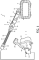
- System 2 adapted to provide a regimen of respiratory therapy to a patient according to one exemplary embodiment of the invention is generally shown in FIG. 1 .
- System 2 includes a pressure generating device 4, a delivery conduit assembly 6 (described in detail herein), and a patient interface device 8 including an elbow conduit 10 fluidly coupled to delivery conduit assembly 6.
- Pressure generating device 4 is structured to generate a flow of breathing gas and may include, without limitation, ventilators, constant pressure support devices (such as a continuous positive airway pressure device, or CPAP device), variable pressure devices (e.g., BiPAP®, Bi-Flex®, or C-FlexTM devices manufactured and distributed by Philips Respironics of Murrysville, Pennsylvania), and auto-titration pressure support devices.
- Delivery conduit assembly 6 is structured to communicate the flow of breathing gas from pressure generating device 4 to patient interface device 8.
- delivery conduit assembly 6 is a heated delivery assembly that also allows for inclusion of an inline accessory 7 (comprising, according to the invention, an oxygen enrichment valve, a pressure valve or a bacteria filter), shown schematically in FIG. 1 , in the flow path from pressure generating device 4 to patient interface device 8.
- patient interface 8 is a nasal/oral mask structured to cover the nose and mouth of the patient.
- any type of patient interface device 8 such as, without limitation, a nasal mask that covers the patient's nose, a nasal cushion having nasal prongs that are received within the patient's nares, or a full face mask that covers the patient's face, which facilitates the delivery of the flow of breathing gas to, and the removal of a flow of exhalation gas from, the airway of a patient may be used while remaining within the scope of the present invention.
- patient interface 8 includes a flexible cushion 16, a rigid or semi-rigid shell 18, and a forehead support 20.
- Straps (not shown) of a headgear component may be attached to shell 18 and forehead support 20 to secure patient interface device 8 to the patient's head.
- An opening in shell 18 to which elbow conduit 10 is coupled allows the flow of breathing gas from pressure generating device 4 to be communicated to an interior space defined by shell 18 and cushion 16, and then, to the airway of a patient.
- the opening in shell 18 also allows the flow of exhalation gas (from the airway of such a patient) to be communicated to an exhaust assembly 12 provided on elbow conduit 10.
- delivery conduit assembly 6 includes a heated tube assembly 22 that is directly fluidly coupled to a first end of an inline accessory adapter 24.
- Delivery conduit assembly 6 further includes inline accessory 7.
- a first end of inline accessory 7 is directly fluidly coupled to a second end of inline accessory adapter 24, and a second end of inline accessory 7 is directly fluidly coupled to heated tube capable outlet port 26 of pressure generating device 4.
- inline accessory adapter 24 is structured to enable the required electrical connection to be made between heated tube capable outlet port 26 and heated tube assembly 22 while simultaneously allowing inline accessory 7 to be inserted into the flow path.
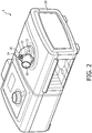
- FIG. 2 is an isometric view of pressure generating device 4 forming part of a respiratory therapy system according to an exemplary embodiment.
- pressure generating device 4 includes a main housing 28 which houses the main components of pressure generating device 4 (e.g., the flow generator (blower), valve(s), sensors, control electronics, etc.).
- Outlet port 26 is coupled to the flow generator and extends from the top side of main housing 28.
- Outlet port 26 includes a tubular port member 30, which in the illustrated embodiment is a standard male iso conical fitting, and a port housing 32 which houses an electrical connector 34.
- Electrical connector 34 is coupled to a power supply and/or other electronics (not shown) provided within main housing 28.
- Port housing 32 further includes slot members 33, the purpose of which is described elsewhere herein.
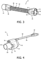
- FIG. 3 is an isometric view of heated tube assembly 22 forming part of a respiratory therapy system according to an exemplary embodiment.
- heated tube assembly 22 includes a proximal end 36, a distal end 38, and heated tubing 40 provided between proximal end 36 and distal end 38.
- Distal end 38 is provided with a coupling member 42 structured to be fluidly coupled to elbow conduit 10, either directly or through intermediate tubing.
- Heated tubing 40 includes a central tubular member 44 surrounded by a helical heating element 46.
- Proximal end 36 is provided with a coupling member 48 that includes a tubular port member 50, which in the illustrated embodiment is a standard female iso conical fitting, and a port housing 52 which houses an electrical connector 54.
- Electrical connector 54 is operatively coupled to heating element 46 of heated tubing 40 to provide power and/or control signals thereto.
- Port housing 52 also includes tab members 53 which are structured to be received within slot members 33 when an inline accessory as described herein is not being used.
- FIG. 4 is an isometric view of inline accessory adapter 24 according to an exemplary embodiment.
- inline accessory adapter 24 includes a fluid coupling member 56 and a jumper wire harness assembly 58.
- Fluid coupling member 56 is structured to provide a fluid connection between proximal end 36 of heated tube assembly 22 and inline accessory 7
- jumper wire harness assembly 58 is structured to provide an electrical connection between heating element 46 of heated tube assembly 22 and outlet port 26 of pressure generating device 4.
- FIG. 5 is an isometric view of fluid coupling member 56 forming part of an adapter apparatus according to an exemplary embodiment.
- Fluid coupling member 56 includes a central coupling member 60 surrounded by a housing member 62.
- FIG. 6 is an isometric view of central coupling member 60 of a fluid coupling member forming part of an adapter apparatus according to an exemplary embodiment.
- central coupling member 60 includes a first end 64 having a tubular port member 66, which in the illustrated embodiment is a standard male iso conical fitting, and a second end 68 having a tubular port member 70, which in the illustrated embodiment is a standard female iso conical fitting.
- Central coupling member 60 also includes a connector housing 72 for receiving and holding a connector member of jumper wire harness assembly 58, and slot members 63 for receiving and mating with tab members 53 of heated tube assembly 22.
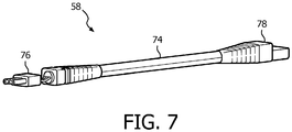
- FIG. 7 is an isometric view of jumper wire harness assembly 58 forming part of an adapter apparatus according to an exemplary embodiment.
- Jumper wire harness assembly 58 includes a cable member 74 comprising a number of wires, a first electrical connector 76 provided at a first end of cable member 74, and a second electrical connector 78 provided at a second end of cable member 74.
- Inline accessory adapter 24 is assembled by inserting the first end of cable member 74 into housing member 62 in a manner wherein first electrical connector 76 is received within connector housing 72 of central coupling member 60.
- inline accessory adapter 24 is coupled to proximal end 36 of heated tube assembly 22. More specifically, tubular port member 66 of inline accessory adapter 24 is coupled to tubular port member 50 of heated tube assembly 22 and tab members 53 are inserted into slot member 63. In addition, electrical connector 54 of heated tube assembly 22 is coupled to first electrical connector 76 provided at the first end of cable member 74 of inline accessory adapter 24. Next, the first end of inline accessory 7 is fluidly coupled to tubular port member 70 of inline accessory adapter 24. Inline accessory 7 has a male fitting 9 that is coupled to tubular port member 70.
- inline accessory 7 is then fluidly coupled to tubular port member 30 of outlet port 26.
- Inline accessory 7 has a female fitting 11 that is coupled to tubular port member 30.
- heated tube assembly 22 being fluidly coupled to outlet port 26 of pressure generating device 4 through inline accessory adapter 24.
- second electrical connector 78 provided at the second end of cable member 74 of inline accessory adapter 24 is coupled to electrical connector 34 of outlet port 26.
- heating element 46 of heated tube assembly 22 being electrically coupled to outlet port 26 of pressure generating device 4 (and thus the power supply of pressure generating device 4) through inline accessory adapter 24.
- inline accessory adapter 24 as just described provides an easy to use mechanism for enabling the required electrical connection to be made between heated tube capable outlet port 26 and heated tube assembly 22 while simultaneously allowing inline accessory 7 to be inserted into the flow path to the user.
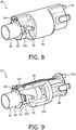
- FIG. 8 is an isometric view of an enrichment adapter 80 according to a comparative example not falling within the scope of the invention.
- Enrichment adapter 80 may be substituted for inline accessory adapter 24 and inline accessory 7 in delivery conduit assembly 6 of FIG. 1 in a comparative example not falling within the scope of the invention to allow oxygen or another supplemental gas to be added to the flow path to patient interface device 8 while at the same time allowing an electrical connection to heated tube assembly 22 from outlet port 26 to be made.
- Enrichment adapter 80 includes a central adapter assembly 82 surrounded by a housing member 84.
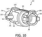
- FIGS. 9 and 10 are front and rear isometric views, respectively, of central adapter assembly 82.
- central adapter assembly 82 includes a first end 84, a second end 86, and a wire harness assembly 98.
- Second end 86 is similar in structure to the proximal end 36 of heated tube assembly 22, and includes a tubular port member 88 (which in the illustrated example is a standard female iso conical fitting) and tab members 89 structured to mate with slot members 33 of outlet port 26.
- tubular port member 88 which in the illustrated example is a standard female iso conical fitting
- tab members 89 structured to mate with slot members 33 of outlet port 26.
- second end 86 is structured to hold a first electrical connector of 100 of a wire harness assembly 98 to enable second end 86 to be fluidly and electrically coupled to outlet port 26 of pressure generating device 4.
- First end 84 includes a coupling member 92 that has a tubular port member 94, which in the illustrated example is a standard male iso conical fitting, a gas inlet port 96 providing access to the internal chamber defined by coupling member 92 to allow supplemental gas, such as oxygen, to be introduced into the flow path to patient interface device 8, a connector housing 102 for receiving and holding a second connector member 104 of wire harness assembly 98, and slot members 103 structured to mate with tab members 53 of heated tube assembly.
- first end 84 is structured to be fluidly and electrically coupled to the proximal end 36 of heated tube assembly 22.
- Second end 86 in the illustrated comparative example further includes a backflow prevention pressure valve 106 structured to prevent the backflow of supplemental gas into pressure generating device 4 when pressure generating device 4 is not operating.
- enrichment adapter 80 as just described is a device that may be inserted in between heated tube assembly 22 and outlet port 26 which, when so inserted, simultaneously provides (i) a main fluid path from pressure generating device 4 to heated tube assembly 22, (ii) a secondary path by which supplemental gas may be introduced into the main flow path, and (iii) electrical connection to heated tube assembly 22 from outlet port 26 by way of a jumper in the form of wire harness assembly 98.
- inline accessory adapter 24 and enrichment adapter 80 may be used with any type of non-heated electrical tube assembly to which an electrical connection must be made, such as, without limitation, an electrical tube assembly that includes one or more wires for carrying an electrical signal from a patient interface device to a base unit and/or from a base unit to a patient interface device.
- any reference signs placed between parentheses shall not be construed as limiting the claim.
- the word “comprising” or “including” does not exclude the presence of elements or steps other than those listed in a claim.
- several of these means may be embodied by one and the same item of hardware.
- the word “a” or “an” preceding an element does not exclude the presence of a plurality of such elements.
- any device claim enumerating several means several of these means may be embodied by one and the same item of hardware.
- the mere fact that certain elements are recited in mutually different dependent claims does not indicate that these elements cannot be used in combination.
Landscapes
- Health & Medical Sciences (AREA)
- Pulmonology (AREA)
- Engineering & Computer Science (AREA)
- General Health & Medical Sciences (AREA)
- Veterinary Medicine (AREA)
- Biomedical Technology (AREA)
- Heart & Thoracic Surgery (AREA)
- Hematology (AREA)
- Life Sciences & Earth Sciences (AREA)
- Animal Behavior & Ethology (AREA)
- Anesthesiology (AREA)
- Public Health (AREA)
- Emergency Medicine (AREA)
- Otolaryngology (AREA)
- Bioinformatics & Cheminformatics (AREA)
- Respiratory Apparatuses And Protective Means (AREA)
- Infusion, Injection, And Reservoir Apparatuses (AREA)
- Pipe Accessories (AREA)
- Percussion Or Vibration Massage (AREA)
- Massaging Devices (AREA)
- Measurement Of The Respiration, Hearing Ability, Form, And Blood Characteristics Of Living Organisms (AREA)
Description
- The present invention pertains to systems for treating conditions, such as sleep disordered breathing, using positive airway pressure (PAP) therapy, and, in particular, to an inline adapter for a pressure support device that also allows for an electrical connection to be made between electrical (e.g., heated tubing) and the pressure support device.
- There are numerous situations where it is necessary or desirable to deliver a flow of breathing gas non-invasively to the airway of a patient, i.e., without intubating the patient or surgically inserting a tracheal tube into the patient's esophagus. For example, it is known to ventilate a patient using a technique known as non-invasive ventilation. It is also known to deliver positive airway pressure (PAP) therapy to treat certain medical disorders, the most notable of which is OSA. Known PAP therapies include continuous positive airway pressure (CPAP), wherein a constant positive pressure is provided to the airway of the patient in order to splint open the patient's airway, and variable airway pressure, wherein the pressure provided to the airway of the patient is varied with the patient's respiratory cycle. Such therapies are typically provided to the patient at night while the patient is sleeping.
- Non-invasive ventilation and pressure support therapies as just described involve the placement of a patient interface device including a mask component having a soft, flexible sealing cushion on the face of the patient. The mask component may be, without limitation, a nasal mask that covers the patient's nose, a nasal/oral mask that covers the patient's nose and mouth, or a full face mask that covers the patient's face. Such patient interface devices may also employ other patient contacting components, such as forehead supports, cheek pads and chin pads. The patient interface device is connected to a gas delivery tube or conduit and interfaces the ventilator or pressure support device with the airway of the patient, so that a flow of breathing gas can be delivered from the pressure/flow generating device to the airway of the patient. It is known to maintain such devices on the face of a wearer by a headgear having one or more straps adapted to fit over/around the patient's head.
- Some patients that use non-invasive ventilation and/or pressure support therapy devices have a need to add an inline accessory to the flow path of the device. Such accessories may include, for example and without limitation, oxygen enrichment adapters, pressure valves and bacteria filters. In addition, many patients are now using heated tubes in the flow path. Such heated tubes require an electrical connection to be made between a connector on the tube cuff and a connector near/on the outlet port of the ventilator or pressure support device. The requirement for such an electrical connection, however, makes it difficult to also use an inline accessory.
- In the specific context of supplemental oxygen, in the prior art, in order to maintain heated tubing functionality while simultaneously receiving supplemental oxygen, the oxygen must be introduced to the patient at the mask side of the patient circuit, either directly into the mask or into an enrichment adapter provided between the mask and the main delivery conduit. This adds bulk to the mask and/or forces the patient to have additional tubing running to their face. This can reduce the comfort of the therapy experience, and thus may lease to decreased therapy compliance.
-
WO 2009/022004 A2 discloses a modular respiratory system to which different parts can be added in a convenient way enabling such upgraded respiratory system to deliver the most comfortable respiratory conditions at an acceptable cost of ownership. -
EP 1 127 583 A2 discoses a conduit which is connectable in a fluid transfer system to provide for the throughflow of a fluid between a transfer device and a patient. The conduit includes a transmission line having a distal end for signal communication with a signal generator and a proximal end connected to a terminal on a mating surface of a female connector and arranged thereon to establish a signal transmission path with a terminal on a mating surface of a second conduit, such as a port of the fluid transfer device, as the mating surfaces engage to establish fluid communication between the conduit and the port. - The present invention provides an adapter apparatus according to claim 1 for a respiratory therapy system having a pressure generating device and an electrical tube assembly, such as a heated tube assembly, coupled to a patient interface device. The adapter apparatus includes a first end having a first port member structured to be fluidly coupled to the electrical tube assembly, a second end having a second port member structured to receive a flow of breathing gas generated by the pressure generating device, the adapter apparatus being structured to deliver the flow of breathing gas to the electrical tube assembly through the first port member, and a wire assembly having a first electrical connector structured to be electrically coupled to the electrical tube assembly and a second electrical connector structured to be electrically coupled to the pressure generating device in order to provide an electrical connection between the electrical tube assembly and the pressure generating device. The adaptor apparatus further comprises an inline accessory device having at a first end a third port member that is structured to be directly coupled to the second port member and having at a second end a fourth port member that is structured to be directly coupled to an outlet port of the pressure generating device, wherein the wire assembly extends along a length of the inline accessory device. The adaptor apparatus further comprises a connector housing, wherein the first electrical connector is received and held within the connector housing. The first port member, the second port member and the connector housing are provided as part of a fluid coupling member, and the fluid coupling member includes a housing that covers the connector housing and receives and holds at least a portion of the jumper wire harness assembly.
- In another embodiment, a respiratory therapy system is provided that includes a pressure generating device structured to generate a flow of breathing gas, a patient interface device, an electrical tube assembly coupled to the patient interface device, and an adapter apparatus according to the invention provided between the pressure generating device and the electrical tube assembly.
- These and other objects, features, and characteristics of the present invention, as well as the methods of operation and functions of the related elements of structure and the combination of parts and economies of manufacture, will become more apparent upon consideration of the following description and the appended claims with reference to the accompanying drawings, all of which form a part of this specification, wherein like reference numerals designate corresponding parts in the various figures. It is to be expressly understood, however, that the drawings are for the purpose of illustration and description only and are not intended as a definition of the limits of the invention, which is defined by the subject-matter of claim 1.
-
-
FIG. 1 is a schematic diagram of a system adapted to provide a regimen of respiratory therapy to a patient according to one exemplary embodiment of the invention; -
FIG. 2 is an isometric view of a pressure generating device forming a part of the system ofFIG. 1 according to one exemplary embodiment of the invention; -
FIG. 3 is an isometric view of a heated tube assembly forming a part of the system ofFIG. 1 according to one exemplary embodiment of the invention; -
FIG. 4 is an isometric view of an inline accessory adapter forming a part of the system ofFIG. 1 according to one exemplary embodiment of the invention; -
FIG. 5 is an isometric view of a fluid coupling member of the inline accessory adapter ofFIG. 4 according to an exemplary embodiment; -
FIG. 6 is an isometric view of a central coupling member of the fluid coupling member ofFIG. 5 ; -
FIG. 7 is an isometric view of a jumper wire harness assembly forming part of the inline accessory adapter ofFIG. 4 according to an exemplary embodiment; -
FIG. 8 is an isometric view of an enrichment adapter that may be used in the system ofFIG. 1 according to a comparative example not falling within the scope of the invention; and -
FIGS. 9 and10 are front and rear isometric views, respectively, of a central adapter assembly forming a part of the enrichment adapter ofFIG. 8 . - As used herein, the singular form of "a", "an", and "the" include plural references unless the context clearly dictates otherwise. As used herein, the statement that two or more parts or components are "coupled" shall mean that the parts are joined or operate together either directly or indirectly, i.e., through one or more intermediate parts or components, so long as a link occurs. As used herein, "directly coupled" means that two elements are directly in contact with each other. As used herein, "fixedly coupled" or "fixed" means that two components are coupled so as to move as one while maintaining a constant orientation relative to each other.
- As used herein, the word "unitary" means a component is created as a single piece or unit. That is, a component that includes pieces that are created separately and then coupled together as a unit is not a "unitary" component or body. As employed herein, the statement that two or more parts or components "engage" one another shall mean that the parts exert a force against one another either directly or through one or more intermediate parts or components. As employed herein, the term "number" shall mean one or an integer greater than one (i.e., a plurality).
- Directional phrases used herein, such as, for example and without limitation, top, bottom, left, right, upper, lower, front, back, and derivatives thereof, relate to the orientation of the elements shown in the drawings and are not limiting upon the claims unless expressly recited therein.
- A
system 2 adapted to provide a regimen of respiratory therapy to a patient according to one exemplary embodiment of the invention is generally shown inFIG. 1 .System 2 includes apressure generating device 4, a delivery conduit assembly 6 (described in detail herein), and apatient interface device 8 including anelbow conduit 10 fluidly coupled todelivery conduit assembly 6. - Pressure generating
device 4 is structured to generate a flow of breathing gas and may include, without limitation, ventilators, constant pressure support devices (such as a continuous positive airway pressure device, or CPAP device), variable pressure devices (e.g., BiPAP®, Bi-Flex®, or C-Flex™ devices manufactured and distributed by Philips Respironics of Murrysville, Pennsylvania), and auto-titration pressure support devices.Delivery conduit assembly 6 is structured to communicate the flow of breathing gas frompressure generating device 4 topatient interface device 8. As described in more detail herein,delivery conduit assembly 6 is a heated delivery assembly that also allows for inclusion of an inline accessory 7 (comprising, according to the invention, an oxygen enrichment valve, a pressure valve or a bacteria filter), shown schematically inFIG. 1 , in the flow path frompressure generating device 4 topatient interface device 8. - In the illustrated embodiment,
patient interface 8 is a nasal/oral mask structured to cover the nose and mouth of the patient. However, any type ofpatient interface device 8, such as, without limitation, a nasal mask that covers the patient's nose, a nasal cushion having nasal prongs that are received within the patient's nares, or a full face mask that covers the patient's face, which facilitates the delivery of the flow of breathing gas to, and the removal of a flow of exhalation gas from, the airway of a patient may be used while remaining within the scope of the present invention. In the embodiment shown inFIG. 1 ,patient interface 8 includes aflexible cushion 16, a rigid orsemi-rigid shell 18, and aforehead support 20. Straps (not shown) of a headgear component may be attached to shell 18 andforehead support 20 to securepatient interface device 8 to the patient's head. An opening inshell 18 to whichelbow conduit 10 is coupled allows the flow of breathing gas frompressure generating device 4 to be communicated to an interior space defined byshell 18 andcushion 16, and then, to the airway of a patient. The opening inshell 18 also allows the flow of exhalation gas (from the airway of such a patient) to be communicated to anexhaust assembly 12 provided onelbow conduit 10. - As seen in
FIG. 1 ,delivery conduit assembly 6 includes aheated tube assembly 22 that is directly fluidly coupled to a first end of aninline accessory adapter 24.Delivery conduit assembly 6 further includes inline accessory 7. In particular, as shown inFIG. 1 , a first end of inline accessory 7 is directly fluidly coupled to a second end of inlineaccessory adapter 24, and a second end of inline accessory 7 is directly fluidly coupled to heated tubecapable outlet port 26 ofpressure generating device 4. In addition, as described in detail below,inline accessory adapter 24 is structured to enable the required electrical connection to be made between heated tubecapable outlet port 26 andheated tube assembly 22 while simultaneously allowing inline accessory 7 to be inserted into the flow path. -
FIG. 2 is an isometric view ofpressure generating device 4 forming part of a respiratory therapy system according to an exemplary embodiment. As seen inFIG. 2 ,pressure generating device 4 includes amain housing 28 which houses the main components of pressure generating device 4 (e.g., the flow generator (blower), valve(s), sensors, control electronics, etc.).Outlet port 26 is coupled to the flow generator and extends from the top side ofmain housing 28.Outlet port 26 includes atubular port member 30, which in the illustrated embodiment is a standard male iso conical fitting, and aport housing 32 which houses anelectrical connector 34.Electrical connector 34 is coupled to a power supply and/or other electronics (not shown) provided withinmain housing 28.Port housing 32 further includesslot members 33, the purpose of which is described elsewhere herein. -
FIG. 3 is an isometric view ofheated tube assembly 22 forming part of a respiratory therapy system according to an exemplary embodiment. As seen inFIG. 3 ,heated tube assembly 22 includes aproximal end 36, adistal end 38, andheated tubing 40 provided betweenproximal end 36 anddistal end 38.Distal end 38 is provided with acoupling member 42 structured to be fluidly coupled toelbow conduit 10, either directly or through intermediate tubing.Heated tubing 40 includes acentral tubular member 44 surrounded by ahelical heating element 46.Proximal end 36 is provided with acoupling member 48 that includes atubular port member 50, which in the illustrated embodiment is a standard female iso conical fitting, and aport housing 52 which houses anelectrical connector 54.Electrical connector 54 is operatively coupled toheating element 46 ofheated tubing 40 to provide power and/or control signals thereto.Port housing 52 also includestab members 53 which are structured to be received withinslot members 33 when an inline accessory as described herein is not being used. -
FIG. 4 is an isometric view of inlineaccessory adapter 24 according to an exemplary embodiment. As seen inFIG. 4 ,inline accessory adapter 24 includes afluid coupling member 56 and a jumperwire harness assembly 58.Fluid coupling member 56 is structured to provide a fluid connection betweenproximal end 36 ofheated tube assembly 22 and inline accessory 7, and jumperwire harness assembly 58 is structured to provide an electrical connection betweenheating element 46 ofheated tube assembly 22 andoutlet port 26 ofpressure generating device 4. -
FIG. 5 is an isometric view offluid coupling member 56 forming part of an adapter apparatus according to an exemplary embodiment.Fluid coupling member 56 includes acentral coupling member 60 surrounded by ahousing member 62.FIG. 6 is an isometric view ofcentral coupling member 60 of a fluid coupling member forming part of an adapter apparatus according to an exemplary embodiment. As seen inFIG. 6 ,central coupling member 60 includes afirst end 64 having atubular port member 66, which in the illustrated embodiment is a standard male iso conical fitting, and asecond end 68 having atubular port member 70, which in the illustrated embodiment is a standard female iso conical fitting.Central coupling member 60 also includes aconnector housing 72 for receiving and holding a connector member of jumperwire harness assembly 58, andslot members 63 for receiving and mating withtab members 53 ofheated tube assembly 22. -
FIG. 7 is an isometric view of jumperwire harness assembly 58 forming part of an adapter apparatus according to an exemplary embodiment. Jumperwire harness assembly 58 includes acable member 74 comprising a number of wires, a firstelectrical connector 76 provided at a first end ofcable member 74, and a secondelectrical connector 78 provided at a second end ofcable member 74. Inlineaccessory adapter 24 is assembled by inserting the first end ofcable member 74 intohousing member 62 in a manner wherein firstelectrical connector 76 is received withinconnector housing 72 ofcentral coupling member 60. - Having described each of the individual parts of
delivery conduit assembly 6, assembly ofdelivery conduit assembly 6 forming part of a respiratory therapy system according to the exemplary embodiment will now be described. First,inline accessory adapter 24 is coupled toproximal end 36 ofheated tube assembly 22. More specifically,tubular port member 66 of inlineaccessory adapter 24 is coupled totubular port member 50 ofheated tube assembly 22 andtab members 53 are inserted intoslot member 63. In addition,electrical connector 54 ofheated tube assembly 22 is coupled to firstelectrical connector 76 provided at the first end ofcable member 74 of inlineaccessory adapter 24. Next, the first end of inline accessory 7 is fluidly coupled totubular port member 70 of inlineaccessory adapter 24. Inline accessory 7 has amale fitting 9 that is coupled totubular port member 70. The second end of inline accessory 7 is then fluidly coupled totubular port member 30 ofoutlet port 26. Inline accessory 7 has afemale fitting 11 that is coupled totubular port member 30. As will be appreciated, this will result inheated tube assembly 22 being fluidly coupled tooutlet port 26 ofpressure generating device 4 throughinline accessory adapter 24. Finally, secondelectrical connector 78 provided at the second end ofcable member 74 of inlineaccessory adapter 24 is coupled toelectrical connector 34 ofoutlet port 26. As will be appreciated, this will result inheating element 46 ofheated tube assembly 22 being electrically coupled tooutlet port 26 of pressure generating device 4 (and thus the power supply of pressure generating device 4) throughinline accessory adapter 24. - Thus,
inline accessory adapter 24 as just described provides an easy to use mechanism for enabling the required electrical connection to be made between heated tubecapable outlet port 26 andheated tube assembly 22 while simultaneously allowing inline accessory 7 to be inserted into the flow path to the user. -
FIG. 8 is an isometric view of anenrichment adapter 80 according to a comparative example not falling within the scope of the invention.Enrichment adapter 80 may be substituted for inlineaccessory adapter 24 and inline accessory 7 indelivery conduit assembly 6 ofFIG. 1 in a comparative example not falling within the scope of the invention to allow oxygen or another supplemental gas to be added to the flow path topatient interface device 8 while at the same time allowing an electrical connection toheated tube assembly 22 fromoutlet port 26 to be made. -
Enrichment adapter 80 includes acentral adapter assembly 82 surrounded by ahousing member 84.FIGS. 9 and10 are front and rear isometric views, respectively, ofcentral adapter assembly 82. As seen inFIGS. 9 and10 ,central adapter assembly 82 includes afirst end 84, asecond end 86, and awire harness assembly 98.Second end 86 is similar in structure to theproximal end 36 ofheated tube assembly 22, and includes a tubular port member 88 (which in the illustrated example is a standard female iso conical fitting) and tab members 89 structured to mate withslot members 33 ofoutlet port 26. As seen inFIGS. 9 and10 and as described in greater detail below,second end 86 is structured to hold a first electrical connector of 100 of awire harness assembly 98 to enablesecond end 86 to be fluidly and electrically coupled tooutlet port 26 ofpressure generating device 4.First end 84 includes acoupling member 92 that has atubular port member 94, which in the illustrated example is a standard male iso conical fitting, agas inlet port 96 providing access to the internal chamber defined by couplingmember 92 to allow supplemental gas, such as oxygen, to be introduced into the flow path topatient interface device 8, aconnector housing 102 for receiving and holding asecond connector member 104 ofwire harness assembly 98, andslot members 103 structured to mate withtab members 53 of heated tube assembly. Thus,first end 84 is structured to be fluidly and electrically coupled to theproximal end 36 ofheated tube assembly 22.Second end 86 in the illustrated comparative example further includes a backflowprevention pressure valve 106 structured to prevent the backflow of supplemental gas intopressure generating device 4 whenpressure generating device 4 is not operating. - Accordingly,
enrichment adapter 80 as just described is a device that may be inserted in betweenheated tube assembly 22 andoutlet port 26 which, when so inserted, simultaneously provides (i) a main fluid path frompressure generating device 4 toheated tube assembly 22, (ii) a secondary path by which supplemental gas may be introduced into the main flow path, and (iii) electrical connection toheated tube assembly 22 fromoutlet port 26 by way of a jumper in the form ofwire harness assembly 98. - In comparative examples not falling within the scope of the invention,
inline accessory adapter 24 andenrichment adapter 80 may be used with any type of non-heated electrical tube assembly to which an electrical connection must be made, such as, without limitation, an electrical tube assembly that includes one or more wires for carrying an electrical signal from a patient interface device to a base unit and/or from a base unit to a patient interface device. - In the claims, any reference signs placed between parentheses shall not be construed as limiting the claim. The word "comprising" or "including" does not exclude the presence of elements or steps other than those listed in a claim. In a device claim enumerating several means, several of these means may be embodied by one and the same item of hardware. The word "a" or "an" preceding an element does not exclude the presence of a plurality of such elements. In any device claim enumerating several means, several of these means may be embodied by one and the same item of hardware. The mere fact that certain elements are recited in mutually different dependent claims does not indicate that these elements cannot be used in combination.
- Although the invention has been described in detail for the purpose of illustration based on what is currently considered to be the most practical and preferred embodiments, it is to be understood that such detail is solely for that purpose and that the invention is not limited to the disclosed embodiments, but, on the contrary, is intended to cover modifications and equivalent arrangements that are within the scope of the appended claims. For example, it is to be understood that the present invention contemplates that, to the extent possible, one or more features of any embodiment can be combined with one or more features of any other embodiment.
Claims (2)
- An adapter apparatus (24) for a respiratory therapy system (2) having a pressure generating device (4) and an electrical heated tube assembly (22) coupled to a patient interface device (8), comprising:a first end having a first port member (66) structured to be fluidly coupled to the electrical heated tube assembly (22);a second end having a second port member (70) structured to receive a flow of breathing gas generated by the pressure generating device (4), the adapter apparatus (24) being structured to deliver the flow of breathing gas to the electrical heated tube assembly (22) through the first port member (66);a jumper wire harness assembly (58) having a first electrical connector (76) structured to be electrically coupled to the electrical heated tube assembly (22) and a second electrical connector (78) structured to be electrically coupled to the pressure generating device (4) in order to provide an electrical connection between the electrical heated tube assembly (22) and the pressure generating device (4);an inline accessory device (7) having at a first end a male fitting (9) that is directly fluidly coupled to the second port member (70) and having at a second end a female fitting (11) that is structured to be directly fluidly coupled to a port member (30) of an outlet port (26) of the pressure generating device (4), wherein the jumper wire harness assembly (58) extends along a length of the inline accessory device (7), and wherein the inline accessory device (7) comprises an oxygen enrichment adapter, a pressure valve or a bacteria filter; a connector housing (72), wherein the first electrical connector (76) is received and held within the connector housing (72); andcharacterized in that
the first port member (66), the second port member (70) and the connector housing (72) are provided as part of a fluid coupling member (56), and the fluid coupling member (56) includes a housing (62) that covers the connector housing (72) and receives and holds at least a portion of the jumper wire harness assembly (58). - A respiratory therapy system (2), comprising:a pressure generating device (4) structured to generate a flow of breathing gas, the pressure generating device comprising an outlet port (26), the outlet port comprising a port member (30);a patient interface device (8);an electrical heated tube assembly (22) coupled to the patient interface device (8); andan adapter apparatus (24) according to claim 1 provided between the pressure generating device and the electrical heated tube assembly, the first port member (66) of the first end of adapter apparatus being fluidly coupled to an end (36) of the electrical heated tube assembly;the second port member (70) of the second end of the adapter apparatus being structured to receive the flow of breathing gas, the second port member connected to the male fitting (9) of the inline accessory device (7), the adapter apparatus being structured to deliver the flow of breathing gas to the electrical heated tube assembly through the first port member;
the female fitting (11) of the inline accessory device being fluidly coupled to the port member (30) of the outlet port (26) of the pressure generating device (4); the first electrical connector (76) of the jumper wire harness assembly (58) of the adapter apparatus being electrically coupled to the electrical heated tube assembly, and the second electrical connector (78) of the jumper wire harness assembly of the adapter apparatus being electrically coupled to the pressure generating device to thereby provide an electrical connection between the electrical heated tube assembly and the pressure generating device.
Priority Applications (1)
| Application Number | Priority Date | Filing Date | Title |
|---|---|---|---|
| EP15200001.4A EP3034122B1 (en) | 2012-12-20 | 2013-12-17 | Inline adapter for a respiratory therapy device |
Applications Claiming Priority (2)
| Application Number | Priority Date | Filing Date | Title |
|---|---|---|---|
| US201261740217P | 2012-12-20 | 2012-12-20 | |
| PCT/IB2013/061037 WO2014097145A1 (en) | 2012-12-20 | 2013-12-17 | Inline adapter for a respiratory therapy device |
Related Child Applications (2)
| Application Number | Title | Priority Date | Filing Date |
|---|---|---|---|
| EP15200001.4A Division EP3034122B1 (en) | 2012-12-20 | 2013-12-17 | Inline adapter for a respiratory therapy device |
| EP15200001.4A Division-Into EP3034122B1 (en) | 2012-12-20 | 2013-12-17 | Inline adapter for a respiratory therapy device |
Publications (2)
| Publication Number | Publication Date |
|---|---|
| EP2934644A1 EP2934644A1 (en) | 2015-10-28 |
| EP2934644B1 true EP2934644B1 (en) | 2019-02-27 |
Family
ID=50001064
Family Applications (2)
| Application Number | Title | Priority Date | Filing Date |
|---|---|---|---|
| EP13824204.5A Active EP2934644B1 (en) | 2012-12-20 | 2013-12-17 | Inline adapter for a respiratory therapy device |
| EP15200001.4A Active EP3034122B1 (en) | 2012-12-20 | 2013-12-17 | Inline adapter for a respiratory therapy device |
Family Applications After (1)
| Application Number | Title | Priority Date | Filing Date |
|---|---|---|---|
| EP15200001.4A Active EP3034122B1 (en) | 2012-12-20 | 2013-12-17 | Inline adapter for a respiratory therapy device |
Country Status (8)
| Country | Link |
|---|---|
| US (1) | US9974917B2 (en) |
| EP (2) | EP2934644B1 (en) |
| JP (1) | JP6378199B2 (en) |
| CN (1) | CN104870042B (en) |
| AU (1) | AU2013365825B2 (en) |
| BR (1) | BR112015014324B1 (en) |
| RU (1) | RU2657953C2 (en) |
| WO (1) | WO2014097145A1 (en) |
Cited By (1)
| Publication number | Priority date | Publication date | Assignee | Title |
|---|---|---|---|---|
| DE102018126886A1 (en) * | 2018-10-19 | 2020-04-23 | Eugen Forschner Gmbh | Connection arrangement |
Families Citing this family (40)
| Publication number | Priority date | Publication date | Assignee | Title |
|---|---|---|---|---|
| SE538414C2 (en) | 2011-08-10 | 2016-06-21 | Fisher & Paykel Healthcare Ltd | Conductor connector for a breathing device for a patient |
| USD747471S1 (en) | 2012-08-10 | 2016-01-12 | Fisher & Paykel Healthcare Limited | Connector |
| USD738489S1 (en) | 2013-05-31 | 2015-09-08 | Resmed Limited | Positive airway pressure delivery console |
| USD738488S1 (en) | 2013-05-31 | 2015-09-08 | Resmed Limited | Positive airway pressure delivery console |
| USD743556S1 (en) | 2014-02-19 | 2015-11-17 | Resmed Limited | Positive airway pressure delivery console |
| USD744108S1 (en) | 2014-02-19 | 2015-11-24 | Resmed Limited | Humidifier reservoir for positive airway pressure delivery console |
| USD762843S1 (en) | 2014-03-18 | 2016-08-02 | Resmed Limited | Air delivery tube |
| USD760258S1 (en) | 2014-05-30 | 2016-06-28 | Resmed Limited | Display screen with graphical user interface |
| CN117414514A (en) * | 2014-07-07 | 2024-01-19 | 费雪派克医疗保健有限公司 | Medical tube and connector for gas delivery system |
| USD809124S1 (en) | 2014-09-12 | 2018-01-30 | Resmed Limited | Pressurized air delivery console |
| USD790683S1 (en) * | 2015-03-11 | 2017-06-27 | Resmed Limited | Pressurized air delivery console |
| AU2016242101B2 (en) | 2015-03-31 | 2020-12-24 | Fisher & Paykel Healthcare Limited | Apparatus for use in a respiratory support system |
| CN118079171A (en) * | 2015-09-04 | 2024-05-28 | 费雪派克医疗保健有限公司 | Catheter connector |
| USD807995S1 (en) | 2015-09-22 | 2018-01-16 | Fisher & Paykel Healthcare Limited | Circuit kit for a humidifier |
| USD841147S1 (en) * | 2015-09-30 | 2019-02-19 | Fisher & Paykel Healthcare Limited | Circuit kit for a humidifier |
| USD805630S1 (en) | 2016-02-02 | 2017-12-19 | Resmed Limited | Air delivery tube |
| USD809656S1 (en) | 2016-06-10 | 2018-02-06 | Fisher & Paykel Healthcare Limited | Connector for a breathing circuit |
| USD841148S1 (en) * | 2016-07-21 | 2019-02-19 | Fisher & Paykel Healthcare Limited | Breathing tube |
| US10953185B2 (en) * | 2017-03-31 | 2021-03-23 | Koninklijke Philips N.V. | Moisture wicking conduit and system |
| USD895788S1 (en) * | 2018-01-30 | 2020-09-08 | Inovytec Medical Solutions Ltd. | Patient circuit for gas delivery |
| JP2021518215A (en) * | 2018-03-20 | 2021-08-02 | アイデヤ ラブズ, エルエルシー | Positive pressure respiratory oil delivery system |
| CN113164702A (en) * | 2018-11-05 | 2021-07-23 | 费雪派克医疗保健有限公司 | Breathing assistance apparatus and/or components thereof |
| CN113038984B (en) * | 2018-11-16 | 2024-07-05 | 皇家飞利浦有限公司 | Valve for pressure support system |
| USD921900S1 (en) | 2018-12-19 | 2021-06-08 | ResMed Pty Ltd | Humidification tub |
| CN112190813A (en) * | 2019-07-08 | 2021-01-08 | 费雪派克医疗保健有限公司 | Medical tubing and connector for breathing circuits |
| WO2021010027A1 (en) * | 2019-07-12 | 2021-01-21 | 株式会社村田製作所 | Cpap device |
| US10737049B1 (en) * | 2019-08-05 | 2020-08-11 | Dynasthetics, Llc | Apparatus for connecting oxygen delivery control instrument to patient delivery device |
| USD1006981S1 (en) | 2019-09-06 | 2023-12-05 | Fisher & Paykel Healthcare Limited | Breathing conduit |
| USD948027S1 (en) | 2019-09-10 | 2022-04-05 | Fisher & Paykel Healthcare Limited | Connector for a breathing conduit |
| EP4051351A1 (en) * | 2019-10-31 | 2022-09-07 | ResMed Sensor Technologies Limited | Systems and methods for injecting substances into a respiratory system |
| USD944938S1 (en) * | 2020-02-26 | 2022-03-01 | Soclean, Inc. | Connector for a sanitizing machine |
| USD957589S1 (en) * | 2020-02-26 | 2022-07-12 | Soclean, Inc. | Connector for a sanitizing machine |
| USD949295S1 (en) * | 2020-02-26 | 2022-04-19 | Soclean Inc. | Connector for a sanitizing machine |
| USD944939S1 (en) * | 2020-02-26 | 2022-03-01 | Soclean, Inc. | Connector for a sanitizing machine |
| USD944941S1 (en) * | 2020-02-27 | 2022-03-01 | Soclean, Inc. | Connector for a sanitizing machine |
| USD940861S1 (en) | 2020-03-03 | 2022-01-11 | Fisher & Paykel Healthcare Limited | Connector for a respiratory system conduit |
| EP4240457A4 (en) * | 2020-11-03 | 2024-09-04 | ResMed Pty Ltd | Respiratory pressure therapy device |
| USD974551S1 (en) | 2020-12-09 | 2023-01-03 | Fisher & Paykel Healthcare Limited | Connector assembly and connector |
| US11986592B2 (en) | 2021-05-14 | 2024-05-21 | Dynasthetics, Llc | Electronic firebreak systems and methods for use with oxygen delivery device |
| USD995758S1 (en) | 2021-06-11 | 2023-08-15 | Fisher & Paykel Healthcare Limited | Tube assembly and connector |
Family Cites Families (21)
| Publication number | Priority date | Publication date | Assignee | Title |
|---|---|---|---|---|
| JPH08317983A (en) * | 1995-03-17 | 1996-12-03 | Teijin Ltd | Aspirating gas supplying apparatus |
| WO1999008738A1 (en) * | 1997-08-14 | 1999-02-25 | Resmed Limited | An apparatus and method for supplying on-demand additional breathable gas |
| SE9704663D0 (en) * | 1997-12-15 | 1997-12-15 | Siemens Elema Ab | Fan system |
| DE19958296C1 (en) * | 1999-12-03 | 2001-09-20 | Map Gmbh | Heated breathing tube for patient has heating element formed by tube wall and consisting of layer of electrically conductive synthetic material, voltage supply line integrated into tube wall |
| SE0000605D0 (en) * | 2000-02-24 | 2000-02-24 | Siemens Elema Ab | Conduit for connecting a fluid transfer device to a patient |
| US7120354B2 (en) * | 2000-03-21 | 2006-10-10 | Fisher & Paykel Healthcare Limited | Gases delivery conduit |
| DE10134725A1 (en) * | 2001-07-17 | 2003-02-06 | Weinmann G Geraete Med | Device for filtering breathing air |
| DE102005000922A1 (en) | 2005-01-07 | 2006-07-20 | Seleon Gmbh | Aerial goggles, nosepiece, Y-piece and procedures |
| US8522782B2 (en) | 2005-09-12 | 2013-09-03 | Mergenet Medical, Inc. | High flow therapy device utilizing a non-sealing respiratory interface and related methods |
| CN101365509A (en) * | 2005-12-14 | 2009-02-11 | 莫哲奈特医疗公司 | High flow therapy device |
| US9855398B2 (en) | 2006-11-08 | 2018-01-02 | Resmed Limited | Humidifier for respiratory apparatus |
| NZ625605A (en) * | 2006-11-08 | 2016-04-29 | Resmed Ltd | Conduit for use in a respiratory apparatus |
| US8770198B2 (en) | 2006-12-21 | 2014-07-08 | Resmed Limited | Connector |
| WO2008105257A1 (en) * | 2007-02-26 | 2008-09-04 | Nec Corporation | High-frequency circuit |
| NZ583968A (en) * | 2007-08-14 | 2012-10-26 | Plastiflex Group | Respiratory system with a humidifier and a pre-conditioning system with a dewpoint controller |
| JP5715950B2 (en) | 2008-08-22 | 2015-05-13 | ブリーズ・テクノロジーズ・インコーポレーテッド | Method and apparatus for providing mechanical ventilation with an open airway interface |
| AU2010206053B2 (en) * | 2009-07-31 | 2014-08-07 | ResMed Pty Ltd | Wire Heated Tube with Temperature Control System, Tube Type Detection, and Active Over Temperature Protection for Humidifier for Respiratory Apparatus |
| NZ716696A (en) * | 2010-09-06 | 2017-08-25 | Resmed Ltd | Methods and apparatus for preventing rainout |
| JP6188682B2 (en) * | 2011-05-20 | 2017-08-30 | コーニンクレッカ フィリップス エヌ ヴェKoninklijke Philips N.V. | Rotary electrical connector and breathing gas supply system using this connector |
| PT2731632T (en) | 2011-07-15 | 2017-12-04 | Soclean Inc | Cpap device with ozone generator |
| WO2013151448A2 (en) | 2012-04-05 | 2013-10-10 | Fisher & Paykel Healthcare Limited | Breathing assistance apparatus with serviceability features |
-
2013
- 2013-12-17 JP JP2015548835A patent/JP6378199B2/en active Active
- 2013-12-17 EP EP13824204.5A patent/EP2934644B1/en active Active
- 2013-12-17 BR BR112015014324-5A patent/BR112015014324B1/en active IP Right Grant
- 2013-12-17 AU AU2013365825A patent/AU2013365825B2/en active Active
- 2013-12-17 RU RU2015129059A patent/RU2657953C2/en active
- 2013-12-17 CN CN201380067180.9A patent/CN104870042B/en active Active
- 2013-12-17 US US14/646,740 patent/US9974917B2/en active Active
- 2013-12-17 WO PCT/IB2013/061037 patent/WO2014097145A1/en active Application Filing
- 2013-12-17 EP EP15200001.4A patent/EP3034122B1/en active Active
Non-Patent Citations (1)
| Title |
|---|
| None * |
Cited By (1)
| Publication number | Priority date | Publication date | Assignee | Title |
|---|---|---|---|---|
| DE102018126886A1 (en) * | 2018-10-19 | 2020-04-23 | Eugen Forschner Gmbh | Connection arrangement |
Also Published As
| Publication number | Publication date |
|---|---|
| RU2657953C2 (en) | 2018-06-18 |
| EP3034122A1 (en) | 2016-06-22 |
| JP2016501608A (en) | 2016-01-21 |
| AU2013365825A1 (en) | 2015-08-06 |
| EP3034122B1 (en) | 2020-09-16 |
| CN104870042A (en) | 2015-08-26 |
| BR112015014324B1 (en) | 2021-05-18 |
| RU2015129059A (en) | 2017-01-26 |
| WO2014097145A1 (en) | 2014-06-26 |
| US9974917B2 (en) | 2018-05-22 |
| JP6378199B2 (en) | 2018-08-22 |
| EP2934644A1 (en) | 2015-10-28 |
| CN104870042B (en) | 2019-01-22 |
| US20150306332A1 (en) | 2015-10-29 |
| AU2013365825B2 (en) | 2018-07-12 |
| BR112015014324A2 (en) | 2017-07-11 |
Similar Documents
| Publication | Publication Date | Title |
|---|---|---|
| EP2934644B1 (en) | Inline adapter for a respiratory therapy device | |
| US10617838B2 (en) | Modular patient interface device with chamber and nasal pillows assembly | |
| US9717873B2 (en) | Rotating electrical connector ADN respiratory gas delivery system employing same | |
| EP2931349B1 (en) | Rotary fluid coupler | |
| US10737052B2 (en) | Fluid coupling member including valve member | |
| US20170319808A1 (en) | Patient interface device with drawstring adjustment | |
| US20130220328A1 (en) | Gas delivery conduit management system | |
| US10369316B2 (en) | Forhead gas supply assembly for a patient interface system | |
| US10507299B2 (en) | Releasable elbow connector | |
| US20130247915A1 (en) | Patient interface device with multi-axis elbow conduit | |
| US20210213228A1 (en) | Mask to tubing adaptor for patient interface device and patient interface device including same | |
| WO2017115215A1 (en) | Custom contoured frame for patient interface device |
Legal Events
| Date | Code | Title | Description |
|---|---|---|---|
| PUAI | Public reference made under article 153(3) epc to a published international application that has entered the european phase |
Free format text: ORIGINAL CODE: 0009012 |
|
| 17P | Request for examination filed |
Effective date: 20150720 |
|
| AK | Designated contracting states |
Kind code of ref document: A1 Designated state(s): AL AT BE BG CH CY CZ DE DK EE ES FI FR GB GR HR HU IE IS IT LI LT LU LV MC MK MT NL NO PL PT RO RS SE SI SK SM TR |
|
| AX | Request for extension of the european patent |
Extension state: BA ME |
|
| DAX | Request for extension of the european patent (deleted) | ||
| 17Q | First examination report despatched |
Effective date: 20160804 |
|
| STAA | Information on the status of an ep patent application or granted ep patent |
Free format text: STATUS: EXAMINATION IS IN PROGRESS |
|
| GRAP | Despatch of communication of intention to grant a patent |
Free format text: ORIGINAL CODE: EPIDOSNIGR1 |
|
| STAA | Information on the status of an ep patent application or granted ep patent |
Free format text: STATUS: GRANT OF PATENT IS INTENDED |
|
| RIC1 | Information provided on ipc code assigned before grant |
Ipc: A61M 16/06 20060101ALN20180815BHEP Ipc: A61M 16/08 20060101AFI20180815BHEP Ipc: A61M 16/00 20060101ALN20180815BHEP Ipc: A61M 16/12 20060101ALN20180815BHEP Ipc: A61M 39/10 20060101ALN20180815BHEP Ipc: A61M 16/20 20060101ALN20180815BHEP Ipc: A61M 16/10 20060101ALI20180815BHEP |
|
| INTG | Intention to grant announced |
Effective date: 20180914 |
|
| GRAS | Grant fee paid |
Free format text: ORIGINAL CODE: EPIDOSNIGR3 |
|
| GRAA | (expected) grant |
Free format text: ORIGINAL CODE: 0009210 |
|
| STAA | Information on the status of an ep patent application or granted ep patent |
Free format text: STATUS: THE PATENT HAS BEEN GRANTED |
|
| AK | Designated contracting states |
Kind code of ref document: B1 Designated state(s): AL AT BE BG CH CY CZ DE DK EE ES FI FR GB GR HR HU IE IS IT LI LT LU LV MC MK MT NL NO PL PT RO RS SE SI SK SM TR |
|
| REG | Reference to a national code |
Ref country code: GB Ref legal event code: FG4D |
|
| REG | Reference to a national code |
Ref country code: CH Ref legal event code: EP |
|
| REG | Reference to a national code |
Ref country code: DE Ref legal event code: R096 Ref document number: 602013051557 Country of ref document: DE |
|
| REG | Reference to a national code |
Ref country code: AT Ref legal event code: REF Ref document number: 1100448 Country of ref document: AT Kind code of ref document: T Effective date: 20190315 |
|
| REG | Reference to a national code |
Ref country code: IE Ref legal event code: FG4D |
|
| REG | Reference to a national code |
Ref country code: NL Ref legal event code: MP Effective date: 20190227 |
|
| REG | Reference to a national code |
Ref country code: LT Ref legal event code: MG4D |
|
| PG25 | Lapsed in a contracting state [announced via postgrant information from national office to epo] |
Ref country code: SE Free format text: LAPSE BECAUSE OF FAILURE TO SUBMIT A TRANSLATION OF THE DESCRIPTION OR TO PAY THE FEE WITHIN THE PRESCRIBED TIME-LIMIT Effective date: 20190227 Ref country code: NL Free format text: LAPSE BECAUSE OF FAILURE TO SUBMIT A TRANSLATION OF THE DESCRIPTION OR TO PAY THE FEE WITHIN THE PRESCRIBED TIME-LIMIT Effective date: 20190227 Ref country code: LT Free format text: LAPSE BECAUSE OF FAILURE TO SUBMIT A TRANSLATION OF THE DESCRIPTION OR TO PAY THE FEE WITHIN THE PRESCRIBED TIME-LIMIT Effective date: 20190227 Ref country code: FI Free format text: LAPSE BECAUSE OF FAILURE TO SUBMIT A TRANSLATION OF THE DESCRIPTION OR TO PAY THE FEE WITHIN THE PRESCRIBED TIME-LIMIT Effective date: 20190227 Ref country code: NO Free format text: LAPSE BECAUSE OF FAILURE TO SUBMIT A TRANSLATION OF THE DESCRIPTION OR TO PAY THE FEE WITHIN THE PRESCRIBED TIME-LIMIT Effective date: 20190527 Ref country code: PT Free format text: LAPSE BECAUSE OF FAILURE TO SUBMIT A TRANSLATION OF THE DESCRIPTION OR TO PAY THE FEE WITHIN THE PRESCRIBED TIME-LIMIT Effective date: 20190627 |
|
| PG25 | Lapsed in a contracting state [announced via postgrant information from national office to epo] |
Ref country code: IS Free format text: LAPSE BECAUSE OF FAILURE TO SUBMIT A TRANSLATION OF THE DESCRIPTION OR TO PAY THE FEE WITHIN THE PRESCRIBED TIME-LIMIT Effective date: 20190627 Ref country code: BG Free format text: LAPSE BECAUSE OF FAILURE TO SUBMIT A TRANSLATION OF THE DESCRIPTION OR TO PAY THE FEE WITHIN THE PRESCRIBED TIME-LIMIT Effective date: 20190527 Ref country code: HR Free format text: LAPSE BECAUSE OF FAILURE TO SUBMIT A TRANSLATION OF THE DESCRIPTION OR TO PAY THE FEE WITHIN THE PRESCRIBED TIME-LIMIT Effective date: 20190227 Ref country code: GR Free format text: LAPSE BECAUSE OF FAILURE TO SUBMIT A TRANSLATION OF THE DESCRIPTION OR TO PAY THE FEE WITHIN THE PRESCRIBED TIME-LIMIT Effective date: 20190528 Ref country code: LV Free format text: LAPSE BECAUSE OF FAILURE TO SUBMIT A TRANSLATION OF THE DESCRIPTION OR TO PAY THE FEE WITHIN THE PRESCRIBED TIME-LIMIT Effective date: 20190227 Ref country code: RS Free format text: LAPSE BECAUSE OF FAILURE TO SUBMIT A TRANSLATION OF THE DESCRIPTION OR TO PAY THE FEE WITHIN THE PRESCRIBED TIME-LIMIT Effective date: 20190227 |
|
| REG | Reference to a national code |
Ref country code: AT Ref legal event code: MK05 Ref document number: 1100448 Country of ref document: AT Kind code of ref document: T Effective date: 20190227 |
|
| PG25 | Lapsed in a contracting state [announced via postgrant information from national office to epo] |
Ref country code: CZ Free format text: LAPSE BECAUSE OF FAILURE TO SUBMIT A TRANSLATION OF THE DESCRIPTION OR TO PAY THE FEE WITHIN THE PRESCRIBED TIME-LIMIT Effective date: 20190227 Ref country code: RO Free format text: LAPSE BECAUSE OF FAILURE TO SUBMIT A TRANSLATION OF THE DESCRIPTION OR TO PAY THE FEE WITHIN THE PRESCRIBED TIME-LIMIT Effective date: 20190227 Ref country code: SK Free format text: LAPSE BECAUSE OF FAILURE TO SUBMIT A TRANSLATION OF THE DESCRIPTION OR TO PAY THE FEE WITHIN THE PRESCRIBED TIME-LIMIT Effective date: 20190227 Ref country code: ES Free format text: LAPSE BECAUSE OF FAILURE TO SUBMIT A TRANSLATION OF THE DESCRIPTION OR TO PAY THE FEE WITHIN THE PRESCRIBED TIME-LIMIT Effective date: 20190227 Ref country code: EE Free format text: LAPSE BECAUSE OF FAILURE TO SUBMIT A TRANSLATION OF THE DESCRIPTION OR TO PAY THE FEE WITHIN THE PRESCRIBED TIME-LIMIT Effective date: 20190227 Ref country code: AL Free format text: LAPSE BECAUSE OF FAILURE TO SUBMIT A TRANSLATION OF THE DESCRIPTION OR TO PAY THE FEE WITHIN THE PRESCRIBED TIME-LIMIT Effective date: 20190227 Ref country code: IT Free format text: LAPSE BECAUSE OF FAILURE TO SUBMIT A TRANSLATION OF THE DESCRIPTION OR TO PAY THE FEE WITHIN THE PRESCRIBED TIME-LIMIT Effective date: 20190227 Ref country code: DK Free format text: LAPSE BECAUSE OF FAILURE TO SUBMIT A TRANSLATION OF THE DESCRIPTION OR TO PAY THE FEE WITHIN THE PRESCRIBED TIME-LIMIT Effective date: 20190227 |
|
| REG | Reference to a national code |
Ref country code: DE Ref legal event code: R097 Ref document number: 602013051557 Country of ref document: DE |
|
| PG25 | Lapsed in a contracting state [announced via postgrant information from national office to epo] |
Ref country code: PL Free format text: LAPSE BECAUSE OF FAILURE TO SUBMIT A TRANSLATION OF THE DESCRIPTION OR TO PAY THE FEE WITHIN THE PRESCRIBED TIME-LIMIT Effective date: 20190227 Ref country code: SM Free format text: LAPSE BECAUSE OF FAILURE TO SUBMIT A TRANSLATION OF THE DESCRIPTION OR TO PAY THE FEE WITHIN THE PRESCRIBED TIME-LIMIT Effective date: 20190227 |
|
| PG25 | Lapsed in a contracting state [announced via postgrant information from national office to epo] |
Ref country code: AT Free format text: LAPSE BECAUSE OF FAILURE TO SUBMIT A TRANSLATION OF THE DESCRIPTION OR TO PAY THE FEE WITHIN THE PRESCRIBED TIME-LIMIT Effective date: 20190227 |
|
| PLBE | No opposition filed within time limit |
Free format text: ORIGINAL CODE: 0009261 |
|
| STAA | Information on the status of an ep patent application or granted ep patent |
Free format text: STATUS: NO OPPOSITION FILED WITHIN TIME LIMIT |
|
| 26N | No opposition filed |
Effective date: 20191128 |
|
| PG25 | Lapsed in a contracting state [announced via postgrant information from national office to epo] |
Ref country code: SI Free format text: LAPSE BECAUSE OF FAILURE TO SUBMIT A TRANSLATION OF THE DESCRIPTION OR TO PAY THE FEE WITHIN THE PRESCRIBED TIME-LIMIT Effective date: 20190227 |
|
| PG25 | Lapsed in a contracting state [announced via postgrant information from national office to epo] |
Ref country code: TR Free format text: LAPSE BECAUSE OF FAILURE TO SUBMIT A TRANSLATION OF THE DESCRIPTION OR TO PAY THE FEE WITHIN THE PRESCRIBED TIME-LIMIT Effective date: 20190227 |
|
| REG | Reference to a national code |
Ref country code: CH Ref legal event code: PL |
|
| REG | Reference to a national code |
Ref country code: BE Ref legal event code: MM Effective date: 20191231 |
|
| PG25 | Lapsed in a contracting state [announced via postgrant information from national office to epo] |
Ref country code: MC Free format text: LAPSE BECAUSE OF FAILURE TO SUBMIT A TRANSLATION OF THE DESCRIPTION OR TO PAY THE FEE WITHIN THE PRESCRIBED TIME-LIMIT Effective date: 20190227 |
|
| PG25 | Lapsed in a contracting state [announced via postgrant information from national office to epo] |
Ref country code: LU Free format text: LAPSE BECAUSE OF NON-PAYMENT OF DUE FEES Effective date: 20191217 Ref country code: IE Free format text: LAPSE BECAUSE OF NON-PAYMENT OF DUE FEES Effective date: 20191217 |
|
| PG25 | Lapsed in a contracting state [announced via postgrant information from national office to epo] |
Ref country code: BE Free format text: LAPSE BECAUSE OF NON-PAYMENT OF DUE FEES Effective date: 20191231 Ref country code: LI Free format text: LAPSE BECAUSE OF NON-PAYMENT OF DUE FEES Effective date: 20191231 Ref country code: CH Free format text: LAPSE BECAUSE OF NON-PAYMENT OF DUE FEES Effective date: 20191231 |
|
| PG25 | Lapsed in a contracting state [announced via postgrant information from national office to epo] |
Ref country code: CY Free format text: LAPSE BECAUSE OF FAILURE TO SUBMIT A TRANSLATION OF THE DESCRIPTION OR TO PAY THE FEE WITHIN THE PRESCRIBED TIME-LIMIT Effective date: 20190227 |
|
| PG25 | Lapsed in a contracting state [announced via postgrant information from national office to epo] |
Ref country code: MT Free format text: LAPSE BECAUSE OF FAILURE TO SUBMIT A TRANSLATION OF THE DESCRIPTION OR TO PAY THE FEE WITHIN THE PRESCRIBED TIME-LIMIT Effective date: 20190227 Ref country code: HU Free format text: LAPSE BECAUSE OF FAILURE TO SUBMIT A TRANSLATION OF THE DESCRIPTION OR TO PAY THE FEE WITHIN THE PRESCRIBED TIME-LIMIT; INVALID AB INITIO Effective date: 20131217 |
|
| PG25 | Lapsed in a contracting state [announced via postgrant information from national office to epo] |
Ref country code: MK Free format text: LAPSE BECAUSE OF FAILURE TO SUBMIT A TRANSLATION OF THE DESCRIPTION OR TO PAY THE FEE WITHIN THE PRESCRIBED TIME-LIMIT Effective date: 20190227 |
|
| PGFP | Annual fee paid to national office [announced via postgrant information from national office to epo] |
Ref country code: GB Payment date: 20231219 Year of fee payment: 11 |
|
| PGFP | Annual fee paid to national office [announced via postgrant information from national office to epo] |
Ref country code: FR Payment date: 20231226 Year of fee payment: 11 |
|
| PGFP | Annual fee paid to national office [announced via postgrant information from national office to epo] |
Ref country code: DE Payment date: 20231227 Year of fee payment: 11 |