RU2657724C2 - Switching system of executive bodies and method of nondestructive testing of operability and disconnection of switching points and executive bodies - Google Patents
Switching system of executive bodies and method of nondestructive testing of operability and disconnection of switching points and executive bodies Download PDFInfo
- Publication number
- RU2657724C2 RU2657724C2 RU2016143638A RU2016143638A RU2657724C2 RU 2657724 C2 RU2657724 C2 RU 2657724C2 RU 2016143638 A RU2016143638 A RU 2016143638A RU 2016143638 A RU2016143638 A RU 2016143638A RU 2657724 C2 RU2657724 C2 RU 2657724C2
- Authority
- RU
- Russia
- Prior art keywords
- power
- power supply
- executive bodies
- supply circuit
- current
- Prior art date
Links
Images
Classifications
-
- G—PHYSICS
- G05—CONTROLLING; REGULATING
- G05B—CONTROL OR REGULATING SYSTEMS IN GENERAL; FUNCTIONAL ELEMENTS OF SUCH SYSTEMS; MONITORING OR TESTING ARRANGEMENTS FOR SUCH SYSTEMS OR ELEMENTS
- G05B19/00—Programme-control systems
- G05B19/02—Programme-control systems electric
- G05B19/04—Programme control other than numerical control, i.e. in sequence controllers or logic controllers
- G05B19/048—Monitoring; Safety
-
- G—PHYSICS
- G05—CONTROLLING; REGULATING
- G05B—CONTROL OR REGULATING SYSTEMS IN GENERAL; FUNCTIONAL ELEMENTS OF SUCH SYSTEMS; MONITORING OR TESTING ARRANGEMENTS FOR SUCH SYSTEMS OR ELEMENTS
- G05B23/00—Testing or monitoring of control systems or parts thereof
- G05B23/02—Electric testing or monitoring
- G05B23/0205—Electric testing or monitoring by means of a monitoring system capable of detecting and responding to faults
- G05B23/0218—Electric testing or monitoring by means of a monitoring system capable of detecting and responding to faults characterised by the fault detection method dealing with either existing or incipient faults
- G05B23/0256—Electric testing or monitoring by means of a monitoring system capable of detecting and responding to faults characterised by the fault detection method dealing with either existing or incipient faults injecting test signals and analyzing monitored process response, e.g. injecting the test signal while interrupting the normal operation of the monitored system; superimposing the test signal onto a control signal during normal operation of the monitored system
-
- H—ELECTRICITY
- H01—ELECTRIC ELEMENTS
- H01H—ELECTRIC SWITCHES; RELAYS; SELECTORS; EMERGENCY PROTECTIVE DEVICES
- H01H51/00—Electromagnetic relays
-
- H—ELECTRICITY
- H03—ELECTRONIC CIRCUITRY
- H03K—PULSE TECHNIQUE
- H03K17/00—Electronic switching or gating, i.e. not by contact-making and –breaking
Abstract
Description
Предложенная группа изобретений относится к области электротехники, электроники и может быть использована для управления электропитанием разветвленных систем исполнительных органов, в том числе и одноразового использования, датчиковой и иной аппаратуры, для неразрушающего контроля работоспособности, проверки разобщенности цепей питания и элементов коммутации самого блока управления и исправности исполнительных органов в системах управления повышенной ответственности, где недопустимо включение исполнительного органа при любом одном отказе в системе коммутации исполнительных органов.The proposed group of inventions relates to the field of electrical engineering, electronics and can be used to control the power supply of branched systems of executive bodies, including one-time use, sensors and other equipment, for non-destructive testing of operability, checking the disconnection of power circuits and switching elements of the control unit itself and serviceability executive bodies in management systems of increased responsibility, where the inclusion of the executive body in any Mr. refusal to switching system of the executive bodies.
Для управления и контроля за исполнительными органами в системах коммутации используют силовые ключи, в простейшем случае - реле, контакты которых подключают напряжение электропитания к управляемой аппаратуре и исполнительным органам, или силовые транзисторы, например, с оптическим управлением (оптроны) в ключевом режиме.To control and monitor the executive bodies in switching systems, power switches are used, in the simplest case, relays, the contacts of which connect the power supply voltage to the controlled equipment and executive bodies, or power transistors, for example, with optical control (optocouplers) in key mode.
Реле и транзисторы перед установкой в состав изготовляемой аппаратуры всегда проходят проверку (входной контроль). Сам факт и метод проверки реле и транзисторов с точки зрения данного предложения не является принципиальным. Однако, например, устройство для контроля электромагнитных реле (патент RU 2017197, опубликован 30.07.1994, МПК: G05B 23/02 (2006.01), H01H 49/00 (2006.01)), содержит источник питания, коммутатор и индикаторы контроля, два конденсатора, соединенные через коммутатор с источником питания и через диод с выводами, предназначенными для подключения обмотки испытуемого электромагнитного реле и его контактов. Здесь обмотку реле подключают к заряженному конденсатору и, если реле срабатывает, оно своим контактом подключает обмотку реле к источнику постоянного напряжения и переводит его на самоблокировку. Такой режим работы реле необходим при проверке и при отработке новых реле, чтобы в серийных изделиях они работали безотказно.Relays and transistors are always tested (input control) before being installed in the manufactured equipment. The fact and method of testing relays and transistors from the point of view of this proposal is not fundamental. However, for example, a device for monitoring electromagnetic relays (patent RU 2017197, published July 30, 1994, IPC: G05B 23/02 (2006.01), H01H 49/00 (2006.01)), contains a power source, a switch and control indicators, two capacitors, connected through a switch to a power source and through a diode with leads designed to connect the winding of the tested electromagnetic relay and its contacts. Here, the relay coil is connected to a charged capacitor and, if the relay is triggered, it connects the relay coil to a constant voltage source with its contact and transfers it to self-locking. This mode of operation of the relay is necessary when checking and testing new relays, so that they work flawlessly in serial products.
Вместе с тем, такие устройства не обеспечивают технологическую проверку состояния системы коммутации исполнительных органов на предмет оценки правильности ее сборки (после изготовления) или проверки такой системы коммутации после хранения или в процессе эксплуатации, на отсутствие обрывов, замыкания между цепями коммутируемой аппаратуры, дефектов изоляции и т.п.At the same time, such devices do not provide a technological check of the state of the switching system of executive bodies to assess the correctness of its assembly (after manufacture) or to check such a switching system after storage or during operation, for breaks, short circuits between switched equipment circuits, insulation defects and etc.
Состояние любой аппаратуры, особенно после длительного хранения в условиях воздействия различных факторов, как то - перепады температуры, влажность, вибрации, удары и т.д., может заметно измениться, в частности - со временем, может ухудшиться изоляция между гальванически разобщенными цепями питания приборов этой аппаратуры, от вибрации и ударов могут нарушиться монтаж, появиться непредвиденные обрывы или соединения цепей этой аппаратуры и т.п. Все это может привести к нарушениям работоспособности с непредсказуемыми последствиями. Поэтому любая ответственная аппаратура требует периодического контроля ее состояния, особенно - перед ее использованием. Вместе с тем, контроль недоступных систем управления с целью оценки их технического состояния, к сожалению, также зачастую недоступен.The condition of any equipment, especially after long-term storage under the influence of various factors, such as temperature changes, humidity, vibration, shock, etc., can noticeably change, in particular - over time, the insulation between galvanically separated supply circuits of devices can deteriorate of this equipment, vibration and shock may interfere with the installation, unexpected breaks or connections of the circuits of this equipment, etc. may appear. All this can lead to malfunctions with unpredictable consequences. Therefore, any responsible equipment requires periodic monitoring of its condition, especially before using it. However, the control of inaccessible control systems in order to assess their technical condition, unfortunately, is also often unavailable.
Известен способ испытаний электронного прибора (патент RU 2173872, опубликован 20.09.2001, МПК: G05B 23/02 (2006/01)). Здесь рассматриваются испытания транзисторов на момент перехода из ключевого режима в активный и обратно, в том числе и в составе аппаратуры для подтверждения работоспособности прибора в реальных режимах эксплуатации. При такой, практически экстремальной, проверке сильноточной аппаратуры из-за перегрузки ключа в переходном режиме, он может выйти из строя, что, естественно, недопустимо для недоступных для ремонта систем управления.A known method of testing an electronic device (patent RU 2173872, published September 20, 2001, IPC: G05B 23/02 (2006/01)). Here we examine the tests of transistors at the time of transition from the key mode to the active mode and vice versa, including as part of the equipment to confirm the operability of the device in real operating modes. With this, almost extreme, check of high-current equipment due to overload of the key in the transient mode, it can fail, which, of course, is unacceptable for control systems inaccessible for repair.
Такая проверка может использоваться, скорее всего, в исследовательских целях в режимах, близких к штатным, и даже более жестких, для подтверждения запасов их работоспособности в будущем.Such a check can be used, most likely, for research purposes in modes close to the regular ones, and even more stringent, to confirm the reserves of their performance in the future.
Известны способ и система управления, по меньшей мере, одним исполнительным органом (патент RU 2538337, опубликован 10.01.2015, МПК: G05B 19/042 (2006.01)). При этом имеется в виду, что эта система может управлять по единому алгоритму любым количеством исполнительных органов посредством двух резервирующих блоков управления (A, B) и логической схемы выбора, причем каждый из блоков управления (A, B) выполнен с возможностью самодиагностики. Однако проверяются самодиагностикой блоки управления (А, В), а логическая схема будет работать в объеме собственной логики, даже если произошел некоторый сбой. При этом мощный коммутатор диагностике недоступен и его работоспособность не проверяется. Более того, некоторый исполнительный орган из их числа в схеме может даже «отсутствовать», например, потому что у него «сгорел предохранитель» и управлять им бесполезно, но это системе управления неизвестно. Однако команда для него при фактической необходимости будет сформирована и передана, но не исполнена.A known method and control system for at least one executive body (patent RU 2538337, published 01/10/2015, IPC: G05B 19/042 (2006.01)). It is understood that this system can control according to a single algorithm any number of executive bodies through two redundant control units (A, B) and a logic selection circuit, each of the control units (A, B) being made with the possibility of self-diagnosis. However, the control units (A, B) are checked by self-diagnosis, and the logic circuit will work within the scope of its own logic, even if there is some malfunction. At the same time, a powerful diagnostic switch is unavailable and its performance is not checked. Moreover, some executive body among them may even be “absent” in the circuit, for example, because it has a “fuse blown” and it is useless to operate it, but this is not known to the control system. However, a team for him, if necessary, will be formed and transmitted, but not executed.
Таким образом, известное устройство не обеспечивает проверки работоспособности своих элементов коммутации и исполнительных органов и даже не оценивает - все ли исполнительные органы фактически в составе системы.Thus, the known device does not provide a check of the operability of its switching elements and executive bodies and does not even evaluate whether all the executive bodies are actually part of the system.
Прототипом заявленной системы коммутации исполнительных органов является устройство для контроля управляемых ключей (патент RU 2101748, опубликован 10.01.98, МПК: G05B 23/00 (2006.01), G05B 23/02 (2006.01)), содержащий источник электропитания, два блока включения в составе шин электропитания, рассчитанные на максимальный суммарный ток, фиксирующее устройство, силовые ключи VTi, к которым подключены токозадающие резисторы Ri и, через диоды VDi, подключены исполнительные органы Ki. Данное устройство позволяет проверить управление всех силовых ключей, для чего содержит блок управления силовыми ключами (на схеме не показан).The prototype of the claimed switching system of the executive bodies is a device for controlling controlled keys (patent RU 2101748, published 10.01.98, IPC: G05B 23/00 (2006.01), G05B 23/02 (2006.01)), containing a power source, two power units as part of power buses, designed for the maximum total current, the fixing device, power switches VTi, to which the current-setting resistors Ri are connected and, through the VDi diodes, the Ki actuators are connected. This device allows you to check the management of all power keys, for which it contains a power key control unit (not shown in the diagram).
Недостатков у известного устройства несколько. При любом включенном силовом ключе VTi через токозадающие резисторы Ri всегда протекает некоторый ток, как в режиме проверки, так и в штатном режиме, диоды VDi снижают напряжение на исполнительных органах Ki и выделяют вместе с резисторами некоторую энергию, увеличивая температуру в объеме устройства. Резисторы Ri и диоды VDi при штатной работе устройства являются бесполезными элементами. Блоки включения должны быть рассчитаны на суммарные токи всех одновременно включаемых исполнительных органов. Отказ любого блока включения приведет к отказу всего устройства управления и потребует полного перехода на резервную систему управления. Исполнительные органы Ki в рабочем состоянии каждый управляется одним силовым ключом VTi, что в штатном режиме работы при включенных блоках включения при несанкционированном замыкании любого силового ключа VTi может сформировать нежелательную команду.The disadvantages of the known device are several. With any VTi power switch turned on, a certain current always flows through the current-setting resistors Ri, both in the test mode and in the normal mode, the VDi diodes reduce the voltage on the Ki actuators and release some energy together with the resistors, increasing the temperature in the device volume. Resistors Ri and VDi diodes during normal operation of the device are useless elements. The switching units must be designed for the total currents of all simultaneously included executive bodies. Failure of any switching unit will lead to a failure of the entire control device and will require a complete transition to a backup control system. In Ki, the executive bodies are each controlled by one VTi power key, which in normal operation with the power on when the power blocks are turned on and an unauthorized closure of any power key VTi can form an unwanted command.
Прототипом заявленного способа неразрушающего контроля работоспособности элементов коммутации и исполнительных органов может быть признан способ неразрушающего контроля управляемых силовых ключей упомянутого устройства-прототипа, изложенный в описании устройства для контроля управляемых ключей (патент RU №2101748, опубликован 10.01.98, МПК: G05B 23/00 (2006.01), G05B 23/02 (2006.01). Задача контроля подтвердить работоспособность управляемых силовых ключей или зафиксировать любую неисправность в цепи каждого управляемого силового ключа (замыкание или обрыв). Здесь для контроля работоспособности включают блок питания и при каждом включенном силовом ключе Ki оценивают с помощью фиксирующего устройства выходной сигнал, свидетельствующий о включении силового ключа и протекании контрольного тока определенного уровня через токозадающий резистор Ri. При последующем увеличении входного сигнала фиксирующее устройство формирует второй выходной сигнал, предупреждающий о наличии неисправности силового ключа VTi типа короткого замыкания или силового ключа с недопустимо большим током утечки или пробой одного из диодов VDi (последнее в описании не отражено, но по схеме устройства это выполняется).The prototype of the claimed method of non-destructive testing of the operability of switching elements and executive bodies can be recognized as the method of non-destructive testing of controlled power keys of the prototype device described in the description of the device for controlling controlled keys (patent RU No. 2101748, published January 10, 1998, IPC: G05B 23/00 (2006.01), G05B 23/02 (2006.01). The task of monitoring is to confirm the operability of the controlled power switches or to fix any malfunction in the circuit of each controlled power switch (short circuit or open ). Here, to monitor the operability, the power supply is turned on and, with each power key Ki turned on, an output signal is evaluated using a clamping device, indicating that the power switch is turned on and a certain level of control current flows through the current-setting resistor Ri. With a subsequent increase in the input signal, the clamping device generates a second output signal warning of a fault in the VTi power switch, such as a short circuit or power switch with an unacceptably high leakage current or VDi second one of the diodes (the latter is not reflected in the specification, but according to the scheme is performed).
Основные недостатки известного способа контроля работоспособности элементов коммутации заключаются в том, что он не может проверить разобщенность коммутируемых цепей электропитания аппаратуры и исполнительных органов и не может предотвратить ошибочное (иногда - опасное) включение исполнительного органа при возникновении замыкания единственного ключевого транзистора в его цепи электропитания или из-за ошибки в управлении, не может оценить ток холостого хода устройства (ток утечек всех закрытых ключевых транзисторов), когда все исполнительные органы выключены. При этом деградация ключевых транзисторов, или одного из них, не будет замечена до тех пор, пока ток утечки не достигнет порога срабатывания фиксирующего устройства.The main disadvantages of the known method for monitoring the operability of switching elements are that it cannot check the disconnectedness of the switched power circuits of the equipment and executive bodies and cannot prevent the erroneous (sometimes dangerous) switching on of the executive body when a single key transistor is shorted in its power supply circuit or from - due to a control error, it cannot evaluate the idling current of the device (leakage current of all closed key transistors) when all body organs are turned off. In this case, the degradation of the key transistors, or one of them, will not be noticed until the leakage current reaches the threshold of operation of the fixing device.
Кроме того, при реализации известного способа контроля работоспособности элементов коммутации имеется постоянное потребление тока, как при проверке работоспособности, так и непосредственно при штатной работе исполнительных органов устройства. Здесь при включенных ключевых транзисторах всегда протекают токи по цепям каждого токозадающего резистора.In addition, when implementing the known method for monitoring the operability of switching elements, there is a constant current consumption, both during operability testing, and directly during regular operation of the device’s executive bodies. Here, when the key transistors are turned on, currents always flow through the circuits of each current-setting resistor.
Задачей группы изобретений является улучшение эксплуатационных свойств и расширение функциональных возможностей, обеспечение неразрушающего контроля работоспособности всех силовых ключей, коммутирующих цепи электропитания исполнительных органов и иной аппаратуры «в обесточенном режиме», возможность проверки разобщенности цепей электропитания исполнительных органов, исключение возможности срабатывания исполнительного органа при пробое или ошибочном включении любого одного силового ключа и проверка этого свойства.The task of the group of inventions is to improve the operational properties and expand the functionality, to provide non-destructive testing of the operability of all power switches, switching power supply circuits of executive bodies and other equipment "in a de-energized mode", the ability to check the disconnected power supply circuits of executive bodies, eliminating the possibility of actuating the executive body during breakdown or erroneous inclusion of any one power key and verification of this property.
Техническим результатом группы изобретений является улучшение эксплуатационных свойств и расширение функциональных возможностей за счет обеспечения проверки работоспособности силовых ключей, коммутирующих цепи электропитания исполнительных органов и иной аппаратуры, проверки разобщенности цепей электропитания исполнительных органов, в том числе - до и после выполнения штатного сеанса управления, при этом в «обесточенном режиме» проверяется и подтверждается надежная и безопасная проверка логики управления, исполнения всех команд и работоспособность элементов коммутации исполнительных органов.The technical result of the group of inventions is the improvement of operational properties and the expansion of functionality by providing a test of the operability of power switches, switching power circuits of executive bodies and other equipment, checking the disconnection of power circuits of executive bodies, including before and after performing a regular control session, while in "de-energized mode", a reliable and safe check of the control logic, execution of all commands is checked and confirmed and performance of switching elements of executive bodies.
Технический результат достигается тем, что в систему коммутации исполнительных органов, содержащую блок электропитания с положительной и отрицательной силовыми шинами электропитания (+) и (-), положительную цепь электропитания +E и единую отрицательную цепь электропитания -E, исполнительные органы, силовые ключи с управляющими входами, соединенные последовательно с исполнительными органами и подключенные непосредственно к положительной и отрицательной цепям электропитания +E и -E блок управления и контроля, содержащий источник электропитания ±U, вход управления, обратной связи и контроля и информационный выход, через который цепи управляющих команд соединены с управляющими входами силовых ключей, электрический выключатель цепи электропитания +E, включенный между положительной силовой шиной (+) блока электропитания и положительной цепью электропитания +E, причем в исходном состоянии электрического выключателя положительная цепь электропитания +E отключена от положительной силовой шины (+) блока электропитания, контрольное устройство, имеющее дифференциальный вход и информационный выход с возможностью подключения его к входу блока управления и контроля, введены два одинаковых по сопротивлению токозадающих резистора, подключенные первыми выводами к положительной цепи электропитания +U, имитатор нагрузки, соединенный первым выводом со вторым выводом первого токозадающего резистора, и подключенный своим вторым выводом к единой отрицательной цепи электропитания -E, второй токозадающий резистор вторым выводом соединен с положительной цепью электропитания +E, измерительный мост контрольного устройства, образованный двумя упомянутыми токозадающими резисторами, имитатором нагрузки, и исполнительными органами с силовыми ключами, дифференциальный вход контрольного устройства соединен со вторыми выводами упомянутых токозадающих резисторов, и является входом измерительного моста.The technical result is achieved by the fact that in the switching system of the executive bodies, comprising a power supply unit with positive and negative power supply buses (+) and (-), a positive power supply circuit + E and a single negative power supply circuit -E, actuators, power switches with control inputs connected in series with the executive bodies and connected directly to the positive and negative power supply circuits + E and -E control and monitoring unit containing an electric power source ± U, control input, feedback and control and information output through which the control command circuits are connected to the control inputs of the power switches, an electric power supply circuit breaker + E connected between the positive power bus (+) of the power supply unit and the positive power supply circuit + E moreover, in the initial state of the electric switch, the positive power supply circuit + E is disconnected from the positive power bus (+) of the power supply unit, a control device having a differential input and inf a radiation output with the ability to connect it to the input of the control and monitoring unit, two current-sensing resistors of the same resistance are introduced, connected by the first terminals to the positive power supply circuit + U, a load simulator connected by the first terminal to the second terminal of the first current-sensing resistor and connected by its second terminal to a single negative power supply circuit -E, the second current-generating resistor is connected to the positive power supply circuit + E by the second terminal, measuring bridge of the control device, o razovanny voltage driving the said two resistors, the load simulator, and the executive with the power switches, the differential input of the control device is connected to the second terminals of said voltage driving resistor, and is input to the measuring bridge.
В предложенной системе коммутации исполнительных органов имитатор нагрузки может быть выполнен в виде магазина сопротивлений, с возможностью установки по необходимости сопротивления, равного максимальному или минимальному сопротивлению исполнительного органа из системы коммутации исполнительных органов.In the proposed switching system of the executive bodies, the load simulator can be made in the form of a resistance store, with the possibility of installing, if necessary, the resistance equal to the maximum or minimum resistance of the executive body from the switching system of the executive bodies.
Кроме того, в состав измерительного моста могут быть введены два диода, включенные последовательно с одинаковыми по сопротивлению токозадающими резисторами.In addition, two diodes can be introduced into the measuring bridge, connected in series with the same resistance resistors.
Технический результат достигается тем, что способ неразрушающего контроля работоспособности и разобщенности элементов системы коммутации и исполнительных органов характеризуется тем, что подсчитывают сумму предельно допустимых токов утечки всех выключенных силовых ключей через токозадающий резистор, подают напряжение на цепи электропитания и контроля исполнительных органов от источника электропитания через токозадающий резистор, оценивают фактический уровень тока холостого хода системы коммутации исполнительных органов, сравнивают его с суммой предельно допустимых токов утечки всех выключенных силовых ключей, делают вывод, об отсутствии замечаний в цепях электропитания и среди элементов коммутации исполнительных органов, и проводят проверку работоспособности элементов коммутации, цепей питания и исполнительных органов, для чего поочередно кратковременно включают по одному все силовые ключи, подключенные к положительной цепи электропитания +E исполнительных органов и контролируют суммарный уровень токов утечки, значение которого не должно превышать предельно допустимого уровня суммарного тока утечки всех выключенных силовых ключей, и подтверждают выключенное состояние всех силовых ключей, соединенных последовательно с исполнительными органами и силовыми ключами, подключенными к отрицательной цепи электропитания -E, поочередно кратковременно включают по одному все силовые ключи, подключенные к единой отрицательной цепи электропитания -Е и контролируют суммарный уровень токов утечки, значение которого не должно превышать допустимого уровня суммарного тока утечки всех выключенных силовых ключей, и подтверждают выключенное состояние силовых ключей, соединенных последовательно с исполнительными органами и силовыми ключами, подключенными к положительной цепи электропитания +E, при каждом одном включенном силовом ключе, подключенном к положительной цепи электропитания +E, включением соответствующего силового ключа, подключенного к отрицательной цепи электропитания -E, включают в состав измерительного моста соответствующий исполнительный орган и, изменяя сопротивление имитатора нагрузки, при балансе измерительного моста определяют сопротивление имитатора нагрузки, которое равно сопротивлению включенного исполнительного органа, при каждом одном включенном силовом ключе, подключенном к единой отрицательной цепи электропитания -E, включением соответствующего силового ключа, подключенного к положительной цепи электропитания +E, включают в состав измерительного моста соответствующий исполнительный орган и, изменяя сопротивление имитатора нагрузки, при балансе тока измерительного моста определяют сопротивление имитатора нагрузки, которое равно сопротивлению включенного исполнительного органа, проводят проверку разобщенности элементов коммутации, цепей питания и исполнительных органов, для чего при каждом одном включенном силовом ключе, подключенном к положительной цепи электропитания +E, поочередно кратковременно включают по одному силовому ключу, подключенному к единой отрицательной цепи электропитания -E, кроме силового ключа, связанного своим исполнительным органом с уже включенным силовым ключом, контролируют суммарный уровень тока утечки, значение которого не должно превышать допустимого уровня тока холостого хода, и подтверждают отсутствие ложных электрических связей между цепями электропитания исполнительных органов, при каждом одном включенном силовом ключе, подключенном к единой отрицательной цепи электропитания -E, поочередно кратковременно включают по одному силовому ключу, подключенному к положительной цепи электропитания +E, кроме силового ключа, связанного своим исполнительным органом с уже включенным силовым ключом, контролируют суммарный уровень токов утечки, значение которого не должно превышать допустимого уровня тока холостого хода, и подтверждают отсутствие ложных электрических связей между цепями электропитания исполнительных органов.The technical result is achieved by the fact that the method of non-destructive testing of the operability and disconnection of the elements of the switching system and executive bodies is characterized by the fact that they calculate the sum of the maximum allowable leakage currents of all switched off power switches through a current-setting resistor, supply voltage to the power supply circuit and control the executive bodies from the power supply through the current-setting resistor, evaluate the actual idle current level of the switching system of the executive bodies, comp they are summed up with the sum of the maximum permissible leakage currents of all switched off power switches, they conclude that there are no comments in the power supply circuits and among the switching elements of the executive bodies, and they check the operability of the switching elements, power circuits and executive bodies, for which each one is briefly turned on one by one power switches connected to the positive power supply circuit + E of the executive bodies and control the total level of leakage currents, the value of which should not exceed the permissible level of the total leakage current of all turned off power switches, and confirm the off state of all power switches connected in series with actuators and power switches connected to the negative power supply circuit -E, alternately briefly turn on one all the power switches connected to a single negative circuit power supply -E and control the total level of leakage currents, the value of which should not exceed the permissible level of the total leakage current of all off power keys, and confirm the off state of the power keys connected in series with the actuators and power keys connected to the positive power supply circuit + E, for every one power key turned on, connected to the positive power supply circuit + E, by switching on the corresponding power key connected to the negative -E power supply circuits include the corresponding actuator in the measuring bridge and, changing the resistance of the load simulator, with the balance of the measuring they determine the resistance of the load simulator, which is equal to the resistance of the switched on actuator, for every one switched-on power switch connected to a single negative power supply circuit -E, by switching on the corresponding power switch connected to the positive power supply circuit + E, the corresponding actuator is included in the measuring bridge and, changing the resistance of the load simulator, with the current balance of the measuring bridge determine the resistance of the load simulator, which is equal to resistance of the included executive body, check the disconnectedness of the switching elements, power circuits and executive bodies, for which, with each power switch connected to the positive power supply circuit + E, alternately briefly turn on one power switch connected to the single negative power supply circuit -E , in addition to the power switch connected by its executive body with the power switch already turned on, control the total level of leakage current, the value of which should not be exceed the permissible open-circuit current level, and confirm the absence of false electrical connections between the power circuits of the executive bodies, for every one power key connected to a single negative power supply circuit -E, one power key is connected to the positive power supply circuit + E , in addition to the power switch connected by its executive body with the power switch already turned on, control the total level of leakage currents, the value of which should not be exceed the permissible levels of load current, and confirm the absence of spurious electrical connection between the power supply circuits of the executive bodies.
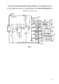
На фиг. 1 приведена схема заявленной системы коммутации исполнительных органов, при этом на схеме фиг. 1 приведены и далее в тексте используются следующие обозначения:In FIG. 1 shows a diagram of the claimed switching system of the executive bodies, while in the diagram of FIG. 1 are given and the following notation is used in the text:
1 - блок электропитания с силовыми положительной (+) и отрицательной (-) шинами электропитания;1 - power supply unit with positive (+) and negative (-) power supply buses;
2-13 - силовые ключи с управляющими входами, соединенные последовательно с исполнительными органами и подключенными непосредственно к цепям электропитания +E и -E;2-13 - power switches with control inputs connected in series with executive bodies and connected directly to the power supply circuits + E and -E;
14-19 - исполнительные органы (при необходимости, иная коммутируемая аппаратура) с раздельными входами управления;14-19 - executive bodies (if necessary, other switched equipment) with separate control inputs;
20 - положительная цепь электропитания +E,20 - positive power supply circuit + E,
21 - единая отрицательная цепь электропитания -E,21 - a single negative power circuit -E,
22 - блок управления и контроля, по необходимости, содержащий источник электропитания с напряжением ±U, блоки памяти (хранения), обработки информации, программирования и т.д., или ЭВМ с необходимым набором функций (на фиг. 1 не показаны),22 - a control and monitoring unit, if necessary, containing a power supply with a voltage of ± U, memory (storage), information processing, programming, etc., or a computer with the necessary set of functions (not shown in Fig. 1),
23 - вход управления, обратной связи и контроля блока управления и контроля 22;23 - input control, feedback and control of the control unit and
24 - информационный выход блока управления и контроля 22;24 - information output of the
25 - электрический выключатель силовой положительной цепи электропитания +E, причем в исходном состоянии выключателя цепь электропитания +E отключена от положительной силовой шины (+) блока электропитания 1,25 - electric switch power positive power supply circuit + E, and in the initial state of the switch, the power supply circuit + E is disconnected from the positive power bus (+) of
26 - контрольное устройство,26 - control device
27 - дифференциальный вход контрольного устройства 26,27 - differential input of the
28 - информационный выход контрольного устройства 26,28 - information output of the
29 и 30 - токозадающие резисторы,29 and 30 - current-causing resistors,
31 - регулируемый вручную имитатор нагрузки, например, магазин сопротивлений, или набор резисторов с необходимыми сопротивлениями,31 - manually adjustable load simulator, for example, a resistance store, or a set of resistors with the necessary resistance,
32 - автоматически регулируемый имитатор нагрузки (на фиг. 1 показан в виде транзистора в режиме регулируемого генератора тока, входящего в состав контрольного устройства 26 и управляемого сигналом контрольного устройства 26); второй вывод любого имитатора нагрузки (31 или 32) соединен с единой отрицательной цепью электропитания 21 -E,32 - automatically adjustable load simulator (in Fig. 1 is shown as a transistor in the mode of an adjustable current generator, which is part of the
33, 34 - диоды,33, 34 - diodes,
35, 36, 37 - блоки исполнительных органов, сгруппированные по их функциональному назначению или по размещению в составе изделия,35, 36, 37 - blocks of executive bodies, grouped by their functional purpose or by placement in the product,
38, 39, 40 - условные наборы цепей (кабели питания) исполнительных органов 14-19,38, 39, 40 - conditional sets of circuits (power cables) of the executive bodies 14-19,
41-52 контакты соединителей системы коммутации исполнительных органов 14-19,41-52 contacts of the connectors of the switching system of the executive bodies 14-19,
53-64 - контакты соединителей блоков 35 -37 исполнительных органов 14-19,53-64 - contacts of the connectors of the blocks 35 -37 of the executive bodies 14-19,
65 и 66 - имитаторы гипотетических элементов паразитных цепей (дефектов), возникающих при появлении каких либо случайных связей, как между цепями электропитания исполнительных органов, так и между элементами системы коммутации исполнительных органов.65 and 66 are simulators of hypothetical elements of parasitic circuits (defects) that arise when any random connections appear, both between the power supply circuits of executive bodies and between elements of the switching system of executive bodies.
Предложенная система коммутации исполнительных органов содержит:The proposed switching system of executive bodies contains:
блок электропитания 1 с силовыми положительной (+) и отрицательной (-) шинами электропитания;
силовые ключи 2-13;power keys 2-13;
исполнительные органы 14-19, имеющие раздельные входы управления;executive bodies 14-19 having separate control inputs;
+E - положительная цепь электропитания 20;+ E - positive
-E - единая отрицательная цепь электропитания 21; в составе изделия, при необходимости, может быть соединена с корпусом изделия или с его общей шиной электропитания GND,-E - single negative
+U, -U - цепи источника электропитания блока управления и контроля 22.+ U, -U - power supply circuits of the control and
Контакты электрического выключателя 25 положительной цепи электропитания +E соединены: один - с силовой положительной шиной (+) блока силового электропитания 1, другой контакт выключателя силовой цепи электропитания 25 соединен с положительной цепью электропитания 20 +E. С этой цепью электропитания 20 соединены силовые ключи 2, 4, 6, 8, 10, 12. С единой отрицательной цепью электропитания 21 -E соединены силовые ключи 3, 5, 7, 9, 11, 13, исполнительные органы 14-19 включены последовательно соответственно между парами силовых ключей 2 и 3, 4 и 5, 6 и 7, 8 и 9, 10 и 11, 12 и 13.The contacts of the positive power
Исполнительные органы 14-19 в системе коммутации соединены последовательно с силовым ключам 2-13 с помощью кабелей питания 38, 39, 40 и разъемных соединителей системы коммутации с контактами 41-52 с одной стороны кабелей питания и контактами 53-64 с другой стороны кабелей питания.The actuators 14-19 in the switching system are connected in series with power switches 2-13 using
Блок управления и контроля 22 имеет вход 23, предназначенный для приема и, при необходимости, сохранения технологических и штатных программ управления, алгоритмов управления и информации обратной связи от контрольного устройства 26, и информационный выход 24, цепи которого связаны с управляющими входами всех силовых ключей 2-13 (показано в общем виде стрелками). Блок управления и контроля 22 должен обеспечивать выдачу в заданной последовательности команд управления силовыми ключами 12-19, обеспечивать, при необходимости, сохранение и анализ информации от контрольного устройства 26 (например, тип проконтролированного исполнительного органа - по его сопротивлению) и т.д. Такое и подобные решения блока управления и контроля 22 имеют много вариантов исполнения, поэтому подробно здесь не рассматриваются и не включены в число признаков заявленной системы коммутации исполнительных органов. Источник электропитания ±U может входить в блок управления и контроля 22. Цепь электропитания -U соединена с единой отрицательной шиной электропитания 21 -E. Этот источник электропитания может быть самостоятельным и размещен за пределами блока управления и контроля 22. Он же может обеспечивать электропитанием и контрольное устройство 26.The control and
Дифференциальный вход 27 контрольного устройства 26 соединен со вторыми выводами токозадающих резисторов 29 и 30 с одинаковыми сопротивлениями и является входом измерительного моста. При этом первые выводы токозадающих резисторов 29 и 30 подключены к положительной цепи +U источника электропитания ±U, имитатор нагрузки 31 соединен первым выводом со вторым выводом первого токозадающего резистора, и подключен своим вторым выводом к единой отрицательной цепи электропитания -E, второй токозадающий резистор вторым выводом соединен с положительной цепью электропитания +E.The
Цепи информационного выхода 28 контрольного устройства 26, при необходимости автоматизации контроля, подключают к входу управления, обратной связи и контроля 23 блока управления и контроля 22.The
Имитатор нагрузки 31 выполнен в виде магазина сопротивлений, с возможностью установки, по необходимости, сопротивления, равного максимальному или минимальному сопротивлению исполнительного органа. Имитатор нагрузки 32 в ручном режиме должен быть отключен.The
Имитатор нагрузки 32 входит в состав контрольного устройства 26, выполнен, как это показано на фиг. 1, и может регулироваться автоматически контрольным устройством 26 до баланса измерительного моста. При этом имитатор нагрузки 31 в автоматическом режиме должен быть отключен.A
Здесь следует отметить, что необходимость, порядок и последовательность включения имитаторов нагрузки 31 или 32 определяется программой, режимом и объемом работы системы коммутации исполнительных органов в составе изделия. Функционально они равнозначны и включаются только по одному.It should be noted that the need, order and sequence of switching on
Каждое из устройств, являющихся функциональным исполнительным органом 14-19, может, при необходимости, содержать некоторые технологические устройства (на фиг. 1 не показаны) для подтверждения по телеметрическому каналу состояния этого устройства в исходном положении, особенности самого устройства и его информационных особенностей и обязанностей: факт подачи напряжения электропитания на исполнительный орган, его состояние «включено/выключено», «положение», «исполнено» и т.п. Это обычная стандартная комплектация исполнительных органов любой системы дистанционного управления исполнительными органами или иной управляемой аппаратурой. Особенности устройства исполнительных органов и их функции не входят в объем притязаний, поэтому в схеме на фиг. 1 и в описании подробно не отражены.Each of the devices, which are the functional executive body 14-19, may, if necessary, contain some technological devices (not shown in FIG. 1) for confirming the status of this device in the initial position, the features of the device itself and its informational features and responsibilities via the telemetry channel : the fact of supplying voltage to the executive body, its state is “on / off”, “position”, “executed”, etc. This is the usual standard equipment of executive bodies of any remote control system of executive bodies or other controlled equipment. Features of the device of executive bodies and their functions are not included in the scope of claims, therefore, in the diagram of FIG. 1 and are not described in detail in the description.
Контрольное устройство 26 совместно с токозадающим резистором 29 и имитатором нагрузки 31 (или 32), с токозадающим резистором 30 и эквивалентным нестационарным сопротивлением Rz системы силовых ключей и исполнительных органов представляют измерительный мост с сопротивлениями плеч R29-R31 (или 32) и R30-Rz., где Rz - электрический эквивалент силовых ключей 2-13 и исполнительных органов и их комбинаций по мере переключения исполнительных органов 14-19 при их проверке.The
Контрольное устройство 26 информацию с информационного выхода 28 может подавать на вход 23 блока управления и контроля 22 по типу «не более» или по типу «не менее», в зависимости от конкретной настройки измерительного устройства 26 и контролируемого диапазона сопротивлений исполнительных органов 14-19, уровня тока холостого хода.The
В составе системы коммутации исполнительных органов 14-19 возможны дефекты, например замыкание цепей, содержащих диоды, транзисторы, резисторы, на фиг. 1 условно показанных в виде гипотетических RD цепочек по типу 65, или цепочки с сопротивлением R, имитирующими ток утечки между дефектными цепями, вплоть до короткого замыкания по типу 66. Эти дефекты уверенно обнаруживаются при проведении проверки на разобщенность цепей. При обнаружении дефекта следует провести анализ причины его появления, принять меры для поиска, устранения дефекта и недопущения возникновения такого дефекта впредь.As a part of the switching system of the executive bodies 14-19, defects are possible, for example, short circuiting of circuits containing diodes, transistors, resistors, in FIG. 1 conditionally shown in the form of hypothetical RD circuits of
С помощью комплекса устройств предложенной системы коммутации исполнительных органов 14-19 можно проверить работоспособность всех силовых ключей 2-13, целостность исполнительных органов и, что не менее важно, разобщенность цепей электропитания исполнительных органов 14-19, находить изменения, вызванные непредсказуемыми дефектами, например, соединениями, обрывами или иными нарушениями в цепях электропитания и контроля исполнительных органов.Using the set of devices of the proposed switching system of the executive bodies 14-19, you can check the performance of all power switches 2-13, the integrity of the executive bodies and, no less important, the disconnection of the power circuits of the executive bodies 14-19, to find changes caused by unpredictable defects, for example, connections, breaks or other violations in the power supply and control circuits of executive bodies.
Поскольку контрольное устройство 26 является неотъемлемой частью системы коммутации исполнительных органов, то сопротивление имитатора нагрузки 31 (или 32) и конкретное устройство его переключения должны быть спроектированы заранее и отлажены в составе конкретной готовой системы коммутации исполнительных органов с учетом ожидаемых параметров комплектующих элементов, в частности - максимального и минимального сопротивления реальных исполнительных органов совместно с сопротивлением открытых (замкнутых) силовых ключей 2-13, с сопротивлением цепей электропитания, токов утечки, составляющих ток холостого хода и т.д.Since the
Если установить сопротивление имитатора нагрузки 31 исходя из максимальной суммы допустимых токов утечки закрытых силовых ключей (максимально допустимого тока холостого хода), то по принципу «не более» в процессе проверки можно подтверждать отсутствие паразитных связей между цепями электропитания исполнительных органов и цепями электропитания -E или +E, способных увеличить ток холостого хода сверх допустимого, а также фиксировать на общем фоне чрезмерно увеличившийся ток утечки любого силового ключа.If you set the resistance of the
Еще следует отметить, что диоды 33 и 34 с одинаковыми параметрами, соединенные последовательно с одинаковыми токозадающими резисторами 29 и 30, практически не влияют на точность измерений при балансе моста и поэтому могут не учитываться в предложенной системе коммутации исполнительных органов именно при балансе моста.It should also be noted that
Исполнительные органы 14-19 по их функциональному назначения или по месту нахождения и т.п. на фиг. 1 могут быть объединены в блоки 35, 36, 37. В реальной аппаратуре такого объединения может не быть.Executive bodies 14-19 according to their functional purpose or location, etc. in FIG. 1 can be combined into
Разъемные контакты 41-42 и 53-64 соединителей и цепи электропитания исполнительных органов 14-19 приведены на фиг. 1 в качестве примера для того, чтобы условно показать, где и какие дефекты типа 65, 66 могут возникнуть в системе коммутации исполнительных органов и как их определить с помощью предложенного способа проверки работоспособности и разобщенности элементов и цепей в конкретной системе коммутации исполнительных органов.The detachable contacts 41-42 and 53-64 of the connectors and the power supply circuit of the actuators 14-19 are shown in FIG. 1 as an example in order to conditionally show where and what defects of
Рассмотрим работу заявленной системы коммутации исполнительных органов с неразрушающим контролем работоспособности элементов коммутации и исполнительных органов (фиг. 1).Consider the operation of the claimed switching system of executive bodies with non-destructive testing of the operability of switching elements and executive bodies (Fig. 1).
В течение срока службы и срока эксплуатации система коммутации исполнительных органов неоднократно выполняет непосредственно те функции, для которых она создана, а именно: управление исполнительными органами 14-19 (штатный режим работы) и проверка результатов исполнения команд, выданных системой коммутации исполнительных органов (в технологическом режиме) Кроме того, при необходимости или по графику, в технологическом режиме проводится проверка работоспособности элементов системы коммутации исполнительных органов 14-19 перед включением ее в штатном режиме и проверка разобщенности цепей системы коммутации исполнительных органов для подтверждений отсутствия каких-либо ошибок или дефектов в цепях управления исполнительных органов (в технологическом режиме).During the service life and life of the operating system, the switching system of the executive bodies repeatedly directly performs the functions for which it was created, namely: managing the executive bodies 14-19 (normal operation) and checking the results of the execution of commands issued by the switching system of the executive bodies (in the technological mode) In addition, if necessary, or according to the schedule, in the technological mode, the operability of the elements of the switching system of the executive bodies 14-19 is checked before switching on it in the normal mode and checking the disconnectedness of the circuits of the switching system of the executive bodies to confirm the absence of any errors or defects in the control circuits of the executive bodies (in the technological mode).
Проверка системы коммутации исполнительных органов 14-19 в режиме, аналогичном штатному, обязательно должна быть проведена при штатном напряжении электропитания +E, со штатными исполнительными органами или с действующими имитаторами исполнительных органов по специальной программе, например, при проведении лабораторных и конструкторско-доводочных испытаний.The verification of the switching system of the executive bodies 14-19 in the mode similar to the standard one must be carried out with the standard supply voltage + E, with the standard executive bodies or with the existing simulators of the executive bodies according to a special program, for example, during laboratory and design-development tests.
Проверка системы коммутации исполнительных органов при приемосдаточных испытаниях и перед штатной эксплуатацией производится всегда в технологическом облегченном режиме, когда не требуется или не допускается подавать на ее исполнительные органы 14-19 штатное напряжение электропитания, но требуется убедиться, что система управления исполнительными органами собрана полностью и правильно и, несмотря на то, что она не запитана рабочим напряжением ±E, убедиться, что она работоспособна, а именно - убедиться, что элементы коммутации - силовые ключи 2-13 работоспособны, цепи электропитания исполнительных органов не имеют электрических связей между собой и с силовыми цепями электропитания и, что до этой конкретной проверки не был разрушен ни один элемент системы коммутации и ни один исполнительный орган.The verification of the switching system of the executive bodies during acceptance tests and before regular operation is always carried out in technological lightweight mode, when it is not required or not allowed to supply the standard power supply voltage to its executive bodies 14-19, but it is necessary to make sure that the control system of the executive bodies is assembled completely and correctly and, despite the fact that it is not powered by an operating voltage of ± E, make sure that it is operational, namely, make sure that the switching elements are power to Luchs 2-13 are operational, the power supply circuits of the executive bodies do not have electrical connections between each other and with the power supply circuits, and that prior to this specific check, not a single element of the switching system and not a single executive body were destroyed.
Перед проверкой работоспособности элементов системы коммутации исполнительных органов подсчитывают (согласно технической документации на силовые ключи) сумму предельно допустимых токов утечки через все пары выключенных силовых ключей 2-13 и через токозадающий резистор 29. В процессе любой проверки ток холостого хода включенной в технологическом режиме системы коммутации исполнительных органов не должен превышать суммы допустимых токов утечки холостого хода, если иное не оговорено особо.Before checking the operability of the elements of the switching system of the executive bodies, they calculate (according to the technical documentation for the power switches) the sum of the maximum allowable leakage currents through all pairs of turned off power switches 2-13 and through the current-setting
В технологическом режиме на цепь электропитания +E и на силовые ключи 2, 4, 6, 8, 10 и 12 через токозадающий резистор 29 подают напряжение +U. Поскольку все силовые ключи 2-13 и электрический выключатель 25 разомкнуты, то через токозадающий резистор 29 никакой иной постоянный ток не течет, кроме тока холостого хода, который всегда должен быть меньше допустимой суммы токов утечки всех пар закрытых силовых ключей 2-13, соединенных последовательно с исполнительными органами 14-19.In technological mode, + U is supplied to the power supply circuit + E and to the power switches 2, 4, 6, 8, 10, and 12 through a current-setting
Измеряют реальный ток холостого хода, сравнивают его измеренное значение с предельно допустимым током холостого хода и делают вывод об отсутствии замечаний в цепях электропитания.The actual open-circuit current is measured, its measured value is compared with the maximum permissible open-circuit current, and a conclusion is made that there are no comments in the power supply circuits.
Для начала проверки в режиме «ТЕСТ» включают блок управления и контроля 22, включают блок электропитания 1 и не подключают при этом его шину (+) к цепи электропитания +E: (электрический выключатель 25 должен находиться в исходном, выключенном, положении). Силовое положительное напряжение (+) электропитания на цепь электропитания +E в режиме «ТЕСТ» подавать нельзя. В режиме «ТЕСТ» его присутствие не обязательно, хотя и желательно, чтобы в процессе проверки убедиться, что оно или его шины электропитания не искажают результатов проверки, например, за счет каких-нибудь дефектов типа чрезмерных токов утечки, ошибок в монтаже и т.п.To start the test in the "TEST" mode, turn on the control and
Способ неразрушающего контроля работоспособности и разобщенности элементов системы коммутации и исполнительных органов состоит в следующем:The method of non-destructive testing of the health and disunity of the elements of the switching system and the executive bodies is as follows:
согласно технической документации на силовые ключи подсчитывают сумму предельно допустимых токов утечки всех выключенных силовых ключей 2-13 через токозадающий резистор 29,according to the technical documentation for the power switches, the sum of the maximum allowable leakage currents of all switched off power switches 2-13 is calculated through the current-setting
подают напряжение +U на цепь электропитания +E от источника электропитания ±U через токозадающий резистор 29,supply voltage + U to the power supply circuit + E from the power supply ± U through the current-setting
оценивают фактический уровень тока холостого хода элементов коммутации исполнительных органов, сравнивают его с суммой предельно допустимых токов утечки всех выключенных силовых ключей 2-13,evaluate the actual idle current level of the switching elements of the executive bodies, compare it with the sum of the maximum allowable leakage currents of all off power switches 2-13,
делают вывод об отсутствии замечаний в цепях электропитания 20 +E и 21 -E и элементов коммутации исполнительных органов 14-19, иconclude that there are no comments in the
проводят проверку работоспособности элементов коммутации, цепей электропитания 20 +E и 21-E и исполнительных органов 14-19, для чегоcheck the performance of switching elements,
поочередно кратковременно включают по одному силовые ключи 2, 4, 6, 8, 10, 12, подключенные к положительной цепи электропитания 20+E и контролируют суммарный уровень токов утечки, значение которого не должно превышать предельно допустимого уровня суммарного тока утечки всех выключенных силовых ключей, и подтверждают выключенное состояние силовых ключей 3, 5, 7, 9, 11, 13, соединенных последовательно с исполнительными органами 14-19 и силовыми ключами 2, 4, 6, 8, 10, 12, подключенными к единой отрицательной цепи электропитания 21 -E,alternately briefly turn on the power switches 2, 4, 6, 8, 10, 12 one at a time, connected to the positive
поочередно кратковременно включают по одному силовые ключи 3, 5, 7, 9, 11, 13, подключенные к единой отрицательной цепи электропитания 21 -E и контролируют суммарный уровень токов утечки, значение которого не должно превышать предельно допустимого уровня суммарного тока утечки всех выключенных силовых ключей, и подтверждают выключенное состояние силовых ключей 2, 4, 6, 8, 10, 12, соединенных последовательно с исполнительными органами 14-19 и силовыми ключами 3, 5, 7, 9, 11, 13, подключенными к положительной цепи электропитания 20 +E,alternately briefly turn on the power switches 3, 5, 7, 9, 11, 13 one at a time, connected to a single negative power supply circuit 21 -E and control the total level of leakage currents, the value of which should not exceed the maximum permissible level of the total leakage current of all switched off power switches , and confirm the off state of
при каждом одном включенном силовом ключе 2, 4, 6, 8, 10, 12, подключенном к положительной цепи электропитания 20 +E, включением соответствующего силового ключа 3, 5, 7, 9, 11, 13, подключенного к единой отрицательной цепи электропитания 21 -E, включают в состав измерительного моста соответствующий исполнительный орган 14, 15, 16, 17, 18, 19 и, изменяя сопротивление имитатора нагрузки 31, при балансе измерительного моста определяют сопротивление имитатора нагрузки 31, которое равно сопротивлению включенного исполнительного органа,for every one
при каждом одном включенном силовом ключе 3, 5, 7, 9, 11, 13, подключенном к единой отрицательной цепи электропитания 21 -E, включением соответствующего силового ключа 2, 4, 6, 8, 10, 12, подключенного к положительной цепи электропитания 20 +E, включают в состав измерительного моста соответствующий исполнительный орган 14, 15, 16, 17, 18, 19 и, изменяя сопротивление имитатора нагрузки 31, при балансе тока измерительного моста определяют сопротивление имитатора нагрузки 31, которое равно сопротивлению включенного исполнительного органа,with every one
и после этого проводят проверку разобщенности элементов коммутации, цепей питания и исполнительных органов, для чегоand after that they check the disconnectedness of the switching elements, power circuits and executive bodies, for which
при каждом одном включенном силовом ключе 2, 4, 6, 8, 10, 12, подключенном к положительной цепи электропитания 20 +E, поочередно кратковременно включают по одному силовому ключу, подключенному к единой отрицательной цепи электропитания 21 -E, кроме силового ключа, связанного своим исполнительным органом с уже включенным силовым ключом, контролируют суммарный уровень токов утечки, значение которого не должно превышать допустимого уровня тока холостого хода, и подтверждают отсутствие ложных электрических связей между цепями электропитания исполнительных органов,at each one
при каждом одном включенном силовом ключе 3, 5, 7, 9, 11, 13, подключенном к единой отрицательной цепи электропитания 21 -E, поочередно кратковременно включают по одному силовому ключу подключенному к положительной цепи электропитания 20 +E, кроме силового ключа, связанного своим исполнительным органом с уже включенным силовым ключом, контролируют суммарный уровень токов утечки, значение которого не должно превышать допустимого уровня тока холостого хода, и подтверждают отсутствие ложных электрических связей между цепями электропитания исполнительных органов.for every one
При этом при проверке разобщенности цепей в любом случае, на дифференциальном входе 27 контрольного устройства 26 может быть некоторый разбаланс, в наличие которого можно убедиться по напряжению (или коду при цифровом исполнении устройства 26) на информационном выходе 28 контрольного устройства 26. В ручном режиме, изменяя сопротивление имитатора нагрузки 31, можно добиться баланса сигналов на дифференциальном входе 27 моста, контролируя напряжения на информационном выходе 28 и рассчитать значение суммарного тока утечки Iz (тока холостого хода) всех параллельно включенных цепей закрытых силовых ключей, соединенных попарно последовательно с исполнительными органами согласно фиг. 1, по формуле (1):At the same time, when checking the disconnected circuits in any case, there can be some imbalance on the
где: Iz - ток холостого хода - суммарный ток утечки всех закрытых силовых ключей, включенных параллельно в несколько цепей по два силовых ключа с исполнительным органом в каждой, при этом ток утечки в каждой такой цепочке определяется ![]()
![]()
U - напряжение на резисторе R31 при балансе моста (практически равное напряжению источника питания блока управления и контроля 22, поскольку токи утечки обычно составляют микроамперы и падением напряжения на резисторе 30 можно пренебречь),U is the voltage across resistor R31 when the bridge is balanced (almost equal to the voltage of the power source of the control and
R31 - сопротивление имитатора нагрузки 31 при балансе моста на дифференциальном входе 27 контрольного устройства 26 и закрытом транзисторе имитатора нагрузки 32.R31 - resistance of the
Значения расчетного допустимого тока холостого хода должны быть записаны в технологической документации для проверки токов холостого хода цепей с конкретными силовыми ключами, с конкретными исполнительными органами и в конкретном технологическом режиме проверки.The values of the calculated permissible idling current should be recorded in the technological documentation for checking the idling currents of circuits with specific power switches, with specific executive bodies and in a specific technological test mode.
При необходимости, ток холостого хода можно оценить, например, измеряя высокоомным милливольтметром, подключая его к имитатору нагрузки 31 с известным сопротивлением, после чего по закону Ома рассчитать ток, холостого хода, поделив измеренное напряжение на установленное сопротивление имитатора нагрузки 31. Но балансировку моста все равно необходимо проводить, в противном случае ток через имитатор нагрузки нельзя будет соотнести с током потребления или с током холостого хода реальной аппаратуры.If necessary, the no-load current can be estimated, for example, by measuring with a high-resistance millivoltmeter, connecting it to a
Можно ток холостого хода измерить непосредственно миллиамперметром, при наличии возможности включения его последовательно с имитатором нагрузки 31 при балансе измерительного моста.You can measure the open circuit current directly with a milliammeter, if you can turn it on sequentially with a
Результаты измерения, особенно сопротивления имитатора нагрузки 31, как наиболее доступного, здесь и далее целесообразно записывать для последующего анализа на предмет сравнения с требованиями документации и их стабильности в процессе проверки конкретной системы коммутации и контроля исполнительных органов, например, при разных температурах, при разных напряжениях питания, при разных вариантах включенных силовых ключей даже в одной последовательной цепи и т.п.The measurement results, especially the resistance of the
При включении по одному тех или иных ключей без включения исполнительных органов суммарный ток утечки может незначительно изменяться, поскольку при любом включенном силовом ключе через него течет уже не его ток утечки, а ток утечки другого не включенного силового ключа в этой цепочке, который может быть больше, чем был ток утечки открытого теперь силового ключа. В этом и иных подобных случаях незначительно изменяется суммарный ток утечки, то есть, ток холостого хода системы не включенных исполнительных органов. Если суммарный ток холостого хода заметно увеличивается, значит, ток холостого хода второго, не включенного, силового ключа в контролируемой цепи может быть за пределами допустимого. Этот факт требует проверки и принятия соответствующих мер с последующей перепроверкой токов холостого хода или корректировки ошибки в технической документации.When you turn on one or another key without turning on the actuators, the total leakage current may slightly change, since with any power key turned on, it is no longer the leakage current that flows through it, but the leakage current of the other not turned on power key in this circuit, which may be greater than was the leakage current of the now open power switch. In this and other similar cases, the total leakage current slightly changes, that is, the open circuit current of the system of the not included executive bodies. If the total open-circuit current noticeably increases, then the open-circuit current of the second, not included, power switch in the controlled circuit may be outside the permissible range. This fact requires verification and appropriate measures, followed by re-checking the idle currents or correcting errors in the technical documentation.
Реально ток утечки существует всегда, но в процессе проверки может появиться ток, значительно превышающий предельно допустимый ток холостого хода, за счет дефекта совершенно непредвиденного происхождения. В процессе проверки, изложенной ниже, дефект можно выделить, вычислить и приять меры к разбору причины появления этого дефекта, ее ликвидации и недопущения в дальнейшем.In reality, a leakage current always exists, but during the verification process a current may appear that significantly exceeds the maximum permissible idling current due to a defect of completely unforeseen origin. In the verification process described below, a defect can be identified, calculated and taken to analyze the causes of this defect, its elimination and prevention in the future.
Если разброс сопротивлений исполнительных органов невелик и все они низкоомные, то в качестве имитатора нагрузки 31 целесообразно установить контрольное сопротивление, равное сопротивлению самого высокоомного исполнительного органа с учетом допуска на разброс сопротивления этого исполнительного органа. В таком режиме измерительного моста при всех более низкоомных исполнительных органах, в том числе и при коротком замыкании исполнительного органа выходной сигнал контрольного устройства 26 (например, компаратора или операционного усилителя), условно, будет «положительный», а при более высокоомных и при обрыве - «отрицательный». Для системы управления и контроля 22 такой «положительный» сигнал будет свидетельствовать о целостности проверяемых исполнительных органов и о возможности продолжения проверки.If the dispersion of the resistance of the executive bodies is small and all of them are low-impedance, then as a
Чтобы выявить возможное короткое замыкание исполнительных органов, нужно на имитаторе нагрузки 31 установить новое значение сопротивления, равное сопротивлению самого низкоомного из исполнительных органов с учетом допуска на разброс сопротивления этого исполнительного органа. В таком режиме при коротком замыкании выходной сигнал контрольного устройства 26 будет «положительный» (по типу предыдущих измерений), а при остальных исполнительных органах и при обрыве - «отрицательный».To identify a possible short circuit of the actuators, it is necessary to set a new resistance value on the
Таким образом, при большом количестве однотипных исполнительных органов достаточно устанавливать только два значения сопротивления имитатора нагрузки 31, имитирующие сопротивление самого высокоомного и самого низкоомного из исполнительных органов. И качество такой проверки будет без претензий. Если требуется подтверждение правильности размещения разнотипных исполнительных органов с разными их сопротивлениями, то при проверке каждого очередного исполнительного органа потребуется включение обоих силовых ключей проверяемой цепи, балансировка моста и проверка равенства сопротивления имитатора нагрузки 31 сопротивлению соответствующего исполнительного органа 14-19 согласно технической документации на него. Эта работа может быть проведена вручную или в автоматическом режиме в зависимости от возможностей контрольного устройства 26, информационных связей между измерительным устройством 26 (его выход 28) и блоком управления и контроля 22 (его вход 23) и от программы управления, заложенной в блок управления и контроля 22.Thus, with a large number of executive bodies of the same type, it is sufficient to set only two resistance values of the
Проверяется работоспособность всей системы коммутации и контроля исполнительных органов достаточно просто. При этом проверку каждого исполнительного органа каждым силовым ключом (в том числе и составляющими элементами силового ключа, если силовой ключ резервирован) проводят только индивидуально. Для этого блоком управления и контроля 26 с его выхода 28 на управляющие входы (обмотки реле, входы оптронов и пр.) силовых ключей каждого исполнительного органа (по многопроводной линии с информационного выхода 24) подают необходимые команды на их включение и на выключение. При этом сигнал на выключение исполнительных органов, в зависимости от типа конкретных исполнительных органов, может быть выполнен путем снятия сигнала на включение этого исполнительного органа. Если управление исполнительным органом предусмотрено с запоминанием команды на включение, то предусматривается команда и на его выключение.The performance of the entire switching system and control of executive bodies is checked quite simply. At the same time, the verification of each executive body by each power key (including the components of the power key, if the power key is reserved) is carried out only individually. For this, the control and
Перед подачей первой команды на включение первого силового ключа подсчитывают сумму предельно допустимых токов утечки через все выключенные силовые ключи 2-13 и через токозадающий резистор 29, или используют результаты подсчета сумму предельно допустимых токов утечки через все выключенные силовые ключи, занесенные ранее в техническую документацию, подают напряжение на цепи электропитания от источника электропитания ±U через токозадающий резистор 29, оценивают фактический уровень тока холостого хода системы коммутации исполнительных органов 14-19, сравнивают его с суммой предельно допустимых токов утечки всех выключенных силовых ключей, делают вывод об отсутствии в цепях электропитания и среди элементов коммутации исполнительных органов замечаний и паразитных связей, проводят контроль работоспособности и разобщенности элементов коммутации и исполнительных органов.Before submitting the first command to turn on the first power switch, the sum of the maximum allowable leakage currents through all switched off power switches 2-13 and through the current-setting
С исполнением первой команды блока управления и контроля 22 на включение силового ключа 2 исполнительного органа 14 от цепи электропитания +U при разомкнутом силовом ключе 3 потечет ток утечки по цепи +U-29-20-2-41-53-14-54-42-3-E, значение которого будет включено в сумму токов утечки остальных выключенных ключей и закрытого в данный момент конкретного силового ключа 3. При включенном силовом ключе 2 целесообразно зафиксировать изменение балансировки сбалансированного перед этим измерительного моста за счет возможного увеличения в данный момент конкретного тока утечки в цепи силового ключа 3 в составе общего тока холостого хода.With the execution of the first command of the control and
Изменением сопротивления имитатора нагрузки 31 следует добиться нового баланса моста и по изменению сопротивлению имитатора нагрузки 31 в этом состоянии оценить эквивалентное сопротивление цепи суммарной нагрузки всех элементов коммутации с цепи положительного напряжения электропитания 20 +E на единую отрицательную цепь электропитания 21 -E и сравнить с предыдущим результатом изменения тока холостого хода и сопротивления нагрузки. Новое значение тока холостого хода может незначительно изменится в большую сторону, а сопротивление имитатора нагрузки - в меньшую сторону.By changing the resistance of the
При включенном силовом ключе 2 формируется команда на включение силового ключа 3. С этого момента к цепям электропитания 20 +E и 21 -E, будет подключен исполнительный орган 14, сопротивление которого достаточно низкоомное и известное из конструкторской документации на этот исполнительный орган 14.When the
Все исполнительные органы 14-19 к силовым ключам 2-13 и далее - к цепям электропитания +E и -E подключают с помощью кабелей питания 38, 39, 40 и соединителей с контактами с 41 по 64. Номера контактов с 41 по 64 соединителей в описании без особой надобности не указываются. Указываются только номера включенных силовых ключей и исполнительных органов. При этом цепи протекания тока всегда легко прослеживаются по цепям между силовыми ключами, соединителями и исполнительными органами.All executive bodies 14-19 are connected to power switches 2-13 and further to power supply circuits + E and -E using
Подключение исполнительного органа 14 к схеме моста резко его разбалансирует. Но мост может быть вновь сбалансирован за счет изменения сопротивления имитатора нагрузки 31. При одинаковых сопротивлениях токозадающих резисторов 29 и 30 одинаковыми должны быть и сопротивление имитатора нагрузки 31 и исполнительного органа 14. В данном случае конкретная цепь 2-14-3 имеет низкоомное сопротивление, равное сумме сопротивлений пары открытых (включенных) силовых ключей 2 и 3, сопротивления цепей питания и сопротивления самого исполнительного органа 14. Это суммарное сопротивление многократно меньше Rz эквивалентного сопротивления утечки остальных силовых ключей, тем более что в этом режиме между силовыми цепями 20 +E и 21 -E напряжение может составлять единицы или, даже, доли вольта. Поэтому влиянием «токов утечки» на результаты измерений можно пренебречь.The connection of the
Если измеренное сопротивление этой цепи согласно показаниям имитатора нагрузки 31 существенно меньше, чем должно быть у исполнительного органа 14 согласно его технической документации, значит, где-то параллельно подключилась еще какая-то низкоомная цепь, а это недопустимо и следует искать и устранять дефект.If the measured resistance of this circuit according to the testimony of the
Если измеренное сопротивление этой цепи оказалось больше, чем должно быть по технической документации на исполнительный орган 14, возможны следующие причины: обрыв или ошибка подключения исполнительного органа 14, не включился силовой ключ 3, не был включен силовой ключ 2, команда на включение которого поступила ранее, но не исполнилась, и это не было выявлено ранее, поскольку токи утечки обычно достаточно малы и их контроль производится по принципу «не более», т.е. измеренное значение тока утечки «должно быть не более» допустимого, то при малых значениях токах потребления это изменение трудно зафиксировать. Возможна и «функциональная» причина: «обрыв» цепи исполнительного органа 14, как и любого из последующих подобных исполнительных органов, а именно: после штатной команды, выданной ранее на включение, исполнительный орган 14 не был приведен в исходное состояние командой на выключение (на фиг. 1 не показано), либо у исполнительного органа 14, например, не установлен или сгорел предохранитель.If the measured resistance of this circuit turned out to be greater than it should be according to the technical documentation for the
В любом случае причина отступления от технической документации и в этой части системы коммутации исполнительных органов должна быть выявлена и замечание устранено.In any case, the reason for deviating from the technical documentation in this part of the switching system of the executive bodies should be identified and the remark eliminated.
После устранения замечания или при его отсутствии изначально, подают команду на выключение силового ключа 3. Теперь по разомкнутой цепи вновь потечет ток утечки силового ключа 3. Если он не более допустимого (целесообразно оценивать по сопротивлению имитатора нагрузки при балансе моста, принимая во внимание и токи утечки остальных силовых ключей), подают команду на выключение силового ключа 2.After the remark is eliminated, or if it is absent initially, they give the command to turn off the
После выключения силового ключа 2 контрольное устройство 26 вновь разбалансируется и вновь потребуется его балансировка изменением сопротивления имитатора нагрузки 31. Эта балансировка покажет, что ток холостого хода близок к измеренному ранее, поскольку мост сбалансирован при том же значении сопротивления имитатора нагрузки, при том же напряжении питания, что и ранее, при первой балансировке, до включения каких-либо силовых ключей. Поэтому замечаний нет.After turning off the
Вместе с тем, нет уверенности в том, что силовой ключ 2 был включен, а потом - выключен. При изначально замкнутом ключе 2 это не будет обнаружено. Здесь целесообразно управляемость исполнительного органа 14 дополнительно проверить с помощью иной последовательности подачи тех же команд:However, there is no certainty that
- включить силовой ключ 3,- turn on the
- убедиться, что ток потребления на холостом ходу изменился незначительно, значит силовой ключ 2 не включен и исполнительный орган 14 не подключен к цепям источника электропитания ±U,- make sure that the idle current consumption has not changed significantly, that means the
- включить силовой ключ 2, теперь исполнительный орган 14 подключен к цепям источника электропитания ±U;- turn on the
- выключить силовой ключ 2, теперь исполнительный орган 14 отключен от цепей источника электропитания ±U;- turn off the
- выключить силовой ключ 3.- turn off the
На этом проверка элементов коммутации исполнительного органа 14 закончена полностью. Перед проверкой каждой следующей группы силовых к исполнительного органа все силовые ключи, включенные ранее, должны быть выключены.This verification of the switching elements of the
С исполнением следующей команды блока управления и контроля 22 на включение силового ключа 4 исполнительного органа 15 от цепи электропитания +U потечет ток утечки по цепи +U-29-20-4-43-55-15-56-44-5-E, значение которого будет равно току утечки закрытого в данный момент конкретного силового ключа 5.With the execution of the next command of the control and
Вместе с этим, напряжение с положительной цепи электропитания 20+E через силовой ключ 4, по цепи 43-55 и через дефект 65 попадет на контакт 42 и далее -54-14-53-41-2, а также и еще далее: через элементы паразитной цепи 65, поступит на контакты 42, 54 соединителей и далее по цепи 42-54-14-53-41 на силовой ключ 2, а также с контакта 42 соединителя - на силовой ключ 3. Однако ни по какой цепи ток не потечет, кроме токов утечки, которые трудно оценить. В результате дефект 65 окажется не замеченным, и поэтому «замечаний нет».At the same time, the voltage from the positive
При включенном силовом ключе 4 формируется следующая команда на включение силового ключа 5. С этого момента к цепям электропитания 20 +E и 21 -E будет подключен исполнительный орган 15, сопротивление которого достаточно низкоомное и, обычно, известное. По аналогии с изложенным выше производится балансировка моста и по результатам балансировки оценивается соответствие результатов измерения имитатора нагрузки 31 и реального сопротивления исполнительного органа 15 и его данных по технической документации.When the power switch 4 is turned on, the following command is generated to turn on the
Отступления от технической документации в этой части системы коммутации исполнительных органов не должно быть. Если замечание проявилось, следует провести его анализ, как описано выше при проверке цепей исполнительного органа 14.Deviations from the technical documentation in this part of the switching system of executive bodies should not be. If a remark has appeared, it should be analyzed as described above when checking the chains of the
При отсутствии замечания изначально или, если оно проявилось, было выявлено, устранено и цепи питания исполнительного органа 15 перепроверены, выключают силовые ключи 4 и 5, отключая исполнительный орган 15 от цепей электропитания 20 +E и 21 -E.In the absence of a comment, initially, or if it manifested itself, it was detected, eliminated, and the power circuits of the
Замечаний нет.There are no comments.
Здесь, также как показано выше следует проверить управляемость силового ключа 4, для чего поменять последовательность подачи команд на включение силовых ключей 4 и 5:Here, as shown above, you should check the controllability of the power switch 4, for which change the sequence of commands to turn on the power switches 4 and 5:
- включить силовой ключ 5,- turn on the
- убедиться, что ток потребления на холостом ходу изменился незначительно, значит, силовой ключ 4 не был включен и исполнительный орган 15 не подключился к цепям питания ±U,- make sure that the idle current consumption has not changed significantly, which means that the power switch 4 was not turned on and the
- включить силовой ключ 4, теперь исполнительный орган 15 подключен к цепям источника электропитания ±U;- turn on the power switch 4, now the
- выключить силовой ключ 4, теперь исполнительный орган 15 отключен от цепей источника электропитания ±U;- turn off the power switch 4, now the
- выключить силовой ключ 5.- turn off the
И вывод: замечаний нет.And the conclusion: there are no comments.
На этом проверка элементов коммутации второго исполнительного органа 15 закончена полностью, перед проверкой каждой следующей группы силовых коммутаторов исполнительного органа все силовые ключи, включенные ранее, должны быть выключены.On this, the verification of the switching elements of the second
Аналогично проверяется работа остальных силовых ключей 6-13 по включению исполнительных органов 16-19. При этом результаты измерений при этой проверке должны соответствовать тем, которые записаны в технической документации на проверку соответствующей аппаратуры включения исполнительных органов 16, 17, 18, 19 силовыми ключами 6-13.Similarly, the operation of the remaining power keys 6-13 is checked to enable the executive bodies 16-19. At the same time, the measurement results during this check should correspond to those recorded in the technical documentation for checking the corresponding switching equipment of the
Результаты этой проверки подтверждают работоспособность системы коммутации исполнительных органов.The results of this check confirm the operability of the switching system of the executive bodies.
Здесь следует отметить, что на любое отклонение результатов измерения сопротивления исполнительных органов или токов холостого хода в процессе включения силовых ключей и исполнительных органов всегда следует обращать внимание, производить анализ таких отклонений, например, реальных сопротивлений исполнительных органов и реальных значений токов холостого хода. Результаты проверки должны быть в пределах допусков к фактическим данным, записанным в технической документации на конкретную систему коммутации исполнительных органов. В случае обнаружения какого-либо замечания необходимо проводить анализ причины появления замечания, устранение замечания и перепроверку.It should be noted here that any deviation of the results of measuring the resistance of the actuators or open circuit currents during the switching on of power switches and actuators should always be paid attention to and analysis of such deviations, for example, the real resistances of the actuators and the actual values of the open circuit currents. The results of the verification must be within the tolerances of the actual data recorded in the technical documentation for a specific switching system of the executive bodies. If any remark is found, it is necessary to analyze the reason for the appearance of the remark, eliminate the remark and recheck.
После проверки работы всех пар силовых ключей в цепях с соответствующими исполнительными органами следует обязательно провести проверку разобщенности элементов коммутации и исполнительных органов по принципу «каждый с каждым», поскольку предыдущая проверка так и не обнаружила дефектов 65 и 66, специально показанных в схеме на фиг. 1 тонкими линиями. Только проверка по принципу «каждый с каждым» позволяет выявить любые дефекты между цепями электропитания разных исполнительных органов, в том числе и дефекты с диодами в таких цепях. Такая проверка эквивалентна традиционной проверке сопротивления изоляции между разобщенными цепями и, даже, между разобщенными системами или приборами. Эта же проверка позволила бы обнаружить гипотетические замыкания, например, силовых ключей 2 или 4, если бы они реально имели место.After checking the operation of all pairs of power keys in the circuits with the corresponding executive bodies, it is imperative to check the disconnectedness of the switching elements and the executive bodies according to the “each with each” principle, since the previous check did not reveal
Здесь пришла пора обратить особое внимание на паразитную цепочку 65, показанную дважды на схеме фиг. 1 тонкими линиями, и на паразитную цепочку 66, которые до сих пор «не обнаружены». Паразитные цепочки могли образоваться конструктивно неизвестно где и когда, но в данном случае, при проверке исполнительных органов 14 и 15, они электрически не были замечены.Here it is time to pay special attention to the
Изложенная ниже методика позволяет оперативно провести проверку разобщенности всех цепей электропитания всех исполнительных органов и позволяет выявить любое ложное соединение между любыми цепями электропитания исполнительных органов.The technique described below allows you to quickly check the disconnectedness of all power circuits of all executive bodies and allows you to identify any false connection between any power circuits of executive bodies.
Начинать проверку можно также с включения того же первого по схеме силового ключа 2.You can also start the test by switching on the same
При включенном силовом ключе 2 в цепи электропитания и контроля 20 +E кратковременно последовательно по одному включают все силовые ключи 5, 7, 9, 11 и 13 в цепи электропитания -E, кроме силового ключа 3 (эта комбинация пары включенных силовых ключей 2 и 3 уже проверена ранее без замечаний при проверке цепей электропитания исполнительного органа 14). Замечаний по непредвиденному увеличению тока в процессе такой проверки не было, поскольку при подаче напряжения +U через резистор 29 на цепь 2-41-53-14-54-42 и далее через паразитную цепь 65 ток утечки не пройдет, поскольку на ее входе имеется диод 33, включенный встречно. И замечания не должно быть, если паразитный диод в дефекте 65 высокого качества.When the
Если замечания нет, силовой ключ 2 выключают.If there are no comments, the
Следующим включают в цепи электропитания и контроля 20 +E силовой ключ 4 и на фоне включенного силового ключа 4 последовательно в цепи электропитания -E включают по одному все силовые ключи 3, 7, 9, 11 и 13, кроме силового ключа 5 (комбинация включенных силовых ключей 4 и 5 проверена ранее при проверке цепей исполнительного органа 14; замечаний не было). В процессе проверки первая же комбинация включенных силовых ключей 4 и 3 приводит к непредвиденному результату: измеренный ток холостого хода оказался неожиданно большим. Глядя на схему на фиг. 1, можно объяснить это тем, что между неподвижным контактом замкнутого силового ключа 4 (в цепи +E) и неподвижным контактом разомкнутого силового ключа 3 (в цепи -E) оказался дефект 65, содержащий неизвестные сопротивление и диод, не обнаруженные ранее при проверке предыдущей последовательностью команд. Место появления этого дефекта можно определить просто: если отключить соединитель с контактами 53-56 от блока исполнительных органов 35 и дефект пропадет, значит, нужно вскрывать блок исполнительных органов 35 и искать дефект там. Если после отключения соединителя с контактами 53-56 от блока исполнительных органов 35 дефект сохранился, значит, он в блоке системы коммутации исполнительных органов, поскольку в кабелях питания (между контактами 42 и 43) такой дефект невозможен, потому что в кабелях питания, обычно, нет диодов. Поэтому нужно вскрывать блок системы коммутации исполнительных органов и искать дефект там.Next, the power switch 4 is included in the power supply and
Выявленный дефект 65 мог возникнуть только по ошибке при монтаже или при замыкании между печатными дорожками в самой аппаратуре коммутации (вариант дефекта 65 показан на схеме фиг. 1 непосредственно между нормально разомкнутыми контактами силовых ключей 4 и 3). Балансировка моста с помощью имитатора нагрузки 31 даст оценку сопротивления этого дефекта. Учет падения напряжения на диоде дефекта 65 поможет уточнить значение сопротивления этого дефекта, а это подскажет то место в схеме и конструкции силового коммутатора исполнительных органов, где такие сопротивления применяются.The detected
После устранения дефекта 65 при вновь включенном силовом ключе 4 последовательно поочередно включают по одному силовые ключи 3, 7, 9, 11 и 13 в цепи электропитания -E. Комбинация проверки с силовым ключом 5 проверялась ранее при проверке цепей исполнительного органа 15. Иных замечаний по непредвиденному увеличению тока в процессе этой проверки на соответствие схеме на фиг. 1 больше не может быть, поскольку их больше нет на схеме фиг. 1, предназначенной только для объяснения методов обнаружения подобных дефектов.After eliminating the
Замечаний нет. После этого силовой ключ 4 выключают.There are no comments. After that, the power switch 4 is turned off.
Следующим включают силовой ключ 6. При поочередном кратковременном включении силовых ключей 3, 5, 9, 11 и 13 замечания отсутствуют. И это «предусмотрено» отсутствием дефектов на схеме фиг. 1.The next turn on the
Замечаний нет. После этого силовой ключ 6 выключают.There are no comments. After that, the
Следующим включают силовой ключ 8. Здесь на схеме фиг. 1 приведен вариант дефекта 66, содержащий неизвестное сопротивление, вплоть до короткого замыкания. При включенном силовом ключе 11 через него потечет ток утечки по цепи +U-29-20-8-47-59-17-60-48-9. Появятся дополнительные «токи утечки» по цепям 48-66-49-10 и 66-61-18-62-50-11. Все эти токи небольшие, ранее они не были выявлены, поскольку каждая из упомянутых цепей имеет разомкнутые силовые ключи 9, 10 и 11, а контроль токов таких цепей традиционно производится по принципу «не более…».The power switch 8 is next turned on. Here in the diagram of FIG. Figure 1 shows a variant of
Резюме проверки - «замечания нет».Verification summary - “no comment”.
Далее при включенном силовом ключе 8 и «при отсутствии замечания» поочередно кратковременно включают силовые ключи 3, 5, 7, 11 и 13. При включениях силовых ключей 3, 5 и 7 замечаний в части измерения токов утечки не будет. При включенном силовом ключе 11 появится непредвиденный ток, протекающий по цепи +U-29-20-8-47-59-17-60-66-61-18-62-50-11-21-E. При любом сопротивлении дефекта 66 измерительный мост может быть сбалансирован с помощью изменения сопротивления имитатора нагрузки 31. Сопротивление имитатора нагрузки и будет показывать значение сопротивления, в которое входят сопротивления исполнительных органов 17, 18, сопротивления цепей питания и сопротивление дефекта 66. Если из результата этого измерения вычесть сопротивления исполнительных органов 17 и 18, которые ранее были определены и в остатке будет 1-2 Ома, то наиболее вероятно - это замыкание печатных проводников, либо нормально разомкнутых контактов силовых ключей 9 и 10, либо замыкание между контактами 48 и 49 соединителя кабеля питания или соединителя на корпусе коммутатора исполнительных органов, т.е., внутри конструкции коммутатора исполнительных органов. Если результат измерения сопротивления дефекта 66 значительно больше, то возможна ржавчина, окислы между контактами соединителя, между печатными проводниками или между контактами силовых ключей, возможны какие-то утечки между печатными проводниками коммутатора исполнительных органов. В любом случае требуется разборка системы управления исполнительных органов, начиная с отключения соединителя с контактами 48, 49, поиск и устранение неисправности, после чего - сборка и контрольная проверка, и при положительных результатах, продолжение проверки разобщенности остальных цепей электропитания исполнительных органов.Further, when the power key 8 is turned on and “in the absence of a comment”, the power switches 3, 5, 7, 11 and 13 are turned on alternately for a short time. When the power switch 11 is turned on, an unexpected current will flow through the circuit + U-29-20-8-47-59-17-60-66-61-18-62-50-11-21-E. For any resistance of
Замечаний нет. После этого силовые ключи 8 и 9 выключают.There are no comments. After that, the power switches 8 and 9 are turned off.
Следующим включают силовой ключ 10. При этом в результате устранения в предыдущих операциях дефекта 66 при включенном силовом ключе 10 этот дефект не проявится и измерение покажет, что при поочередном включении силовых ключей 3, 5, 7, 9 и 13 через замкнутый силовой ключ 10 течет только ток утечки по цепи +U-29-10-49-61-18-62-50-11-21-E.Next, turn on the power switch 10. Moreover, as a result of eliminating the
Если бы дефект 66 не был устранен, то при замкнутых силовых ключах 10 и 9 и балансе измерительного моста можно было бы оценить значение сопротивления дефекта 66 и по нему понять, где этот дефект мог образоваться, например, в виде короткого замыкания между контактами 48 и 49 соединителя, или в блоке коммутации. После устранения дефекта, если он не был устранен ранее, необходимо перепроверить разобщенность в объеме, достаточном для подтверждения отсутствия дефекта 66.If the
Замечаний нет. После этого силовой ключ 10 выключают.There are no comments. After that, the power switch 10 is turned off.
Следующим включают силовой ключ 12. Здесь потечет только «ток утечки» по цепи +U-29-12-51-63-19-64-52-13-E, поскольку силовой ключ 13 разомкнут, ток потребления холостого хода не выйдет за пределы допустимого.Next, turn on the
При кратковременном включении силовых ключей 3, 5, 7, 9 и 11 (по аналогии - кроме силового ключа 13) всегда будет протекать только ток холостого хода.When the power switches 3, 5, 7, 9 and 11 are turned on for a short time (by analogy, except for the power switch 13), only the no-load current will always flow.
Замечаний нет. Силовой ключ 12 выключают.There are no comments. The
Здесь следует заметить, что первую часть проверки системы коммутации исполнительных органов 14-19, в которой проверялась работоспособность элементов коммутации и исправность исполнительных органов, можно объединить со второй частью проверки системы коммутации исполнительных органов, в которой проверялась разобщенность цепей электропитания исполнительных органов. Это целесообразно при контрольной проверке, например, при приемо-сдаточных испытаниях, в то время как раздельная проверка системы коммутации исполнительных органов особенно целесообразна при первом включении системы коммутации исполнительных органов для проверки и настройки (если она потребуется), когда, как видно на примерах, приходится по поводу каждого замечания систему коммутации исполнительных органов разбирать, искать дефект, устранять его, собирать и продолжать проверку. Или начинать проверку с начала, в зависимости от выявленного замечания и количества работ, связанных с устранением конкретного замечания. Суммарный объем проверки при этом не изменяется и корректировать формулу изобретения в части способа проверки не требуется.It should be noted that the first part of the verification of the switching system of the executive bodies 14-19, in which the operability of the switching elements and the serviceability of the executive bodies was checked, can be combined with the second part of the verification of the switching system of the executive bodies, in which the disconnection of the power supply circuits of the executive bodies was checked. This is advisable during a control check, for example, during acceptance tests, while a separate check of the switching system of the executive bodies is especially advisable when you first turn on the switching system of the executive bodies for checking and tuning (if necessary), when, as shown in the examples, for each comment, it is necessary to disassemble the switching system of the executive bodies, search for the defect, eliminate it, assemble and continue to check. Or start the test from the beginning, depending on the identified comments and the number of works associated with the elimination of a specific remark. The total scope of the verification does not change, and it is not necessary to adjust the claims in terms of the verification method.
Возможна иная последовательность проверки системы коммутации исполнительных органов, когда все замечания фиксируются по мере их появления, анализируются и только после этого система коммутации исполнительных органов разбирается, а поиск и устранение неисправностей производится «за один заход». Такая методика первой проверки позволит подготовить систему коммутации исполнительных органов более оперативно, только с одной промежуточной «разборкой-ремонтом-сборкой и проверкой», например, перед подготовкой к приемо-сдаточным испытаниям. При этом объем проверки также не изменяется и корректировка формулы изобретения не требуется.A different sequence of checking the switching system of the executive bodies is possible, when all the comments are recorded as they appear, are analyzed and only after that the switching system of the executive bodies is disassembled, and troubleshooting is performed “in one go”. This method of the first check will allow you to prepare the switching system of the executive bodies more quickly, with only one intermediate “disassembly-repair-assembly and check”, for example, before preparing for the acceptance test. However, the scope of the verification also does not change and the adjustment of the claims is not required.
Контрольное устройство 26 на своем информационном выходе (интерфейсе) 28 выставляет результаты измерения тока или сопротивления нагрузки, которые поступают на вход 23 блока управления и контроля 22 для сравнения с ожидаемыми параметрами и принятия решения о выполнении следующей операции проверки. При необходимости, может быть включен световой или звуковой сигнал тревоги, оповещающий об обнаруженном дефекте и остановке проверки до устранения причины замечания. Результаты измерения тока в обоснованных случаях и при наличии необходимой аппаратуры, могут быть представлены, например, для передачи по каналу телеметрии, либо оператору для визуального контроля, либо переданы по каналу связи оператору, находящемуся на расстоянии.The
После проверки работоспособности системы коммутации исполнительных органов в технологическом режиме «в обесточенном состоянии» и ее ремонта, если это потребовалось, и перепроверки после ремонта, можно использовать аппаратуру в штатном режиме, для этого перед работой достаточно включить выключатель 25, выдать заданный объем команд и выключатель 25 выключить. После исполнения штатной программы, при необходимости, можно провести повторную проверку системы коммутации исполнительных органов для контроля исполнения функций исполнительными органами и контроля целостности и работоспособности элементов системы коммутации и исполнительных органов, а именно: появления обрывов, замыканий между цепями исполнительных органов, изменения состояния двухпозиционных или одноразовых исполнительных органов и т.п.After checking the operability of the switching system of the executive bodies in the technological mode "in a de-energized state" and repairing it, if necessary, and checking after repair, you can use the equipment in normal mode, for this it is enough to turn on the
Одновременная работа системы управления исполнительными органами в режиме «РАБОТА» и проверка системы коммутации исполнительных органов в режиме «ТЕСТ» не допускается, поскольку в этом случае от команд режима ТЕСТ могут быть случайно несвоевременно включены исполнительные органы, способные навредить. Для этого в «вышестоящей» системе управления блоком питания 1, положительной цепью электропитания 20 +E и выключателем 25 должна быть предусмотрена необходимая блокировка.Simultaneous operation of the control system of the executive bodies in the “WORK” mode and verification of the switching system of the executive bodies in the “TEST” mode is not allowed, since in this case, the executive bodies that could do harm could be accidentally switched on from the TEST mode commands. To do this, in the "higher" control system of the
В целом следует отметить способность заявленной группы изобретений обеспечивать проверку работоспособности силовых ключей, их разобщенность, их возможности управлять исполнительными органами, проверку целостности исполнительных органов и при этом фиксировать гипотетические неисправности аппаратуры (например, сгоревших предохранителей, не исходное состояние двухпозиционных исполнительных органов, состояние одноразовых исполнительных органов и др.) при отключенном силовом электропитании, т.е. «в обесточенном состоянии».In general, it should be noted the ability of the claimed group of inventions to verify the operability of power keys, their disunity, their ability to control executive bodies, check the integrity of executive bodies and at the same time record hypothetical hardware failures (for example, blown fuses, non-initial state of on-off executive bodies, state of disposable executive organs, etc.) when the power supply is turned off, i.e. "De-energized."
Кроме того, следует отметить, что такие проверки целесообразно проводить не только после изготовления системы коммутации исполнительных органов или при приемо-сдаточных испытаниях, что выполняется обязательно, но и перед применением системы коммутации исполнительных органов в штатном режиме работы. Это необходимо после длительного нахождения в выключенном состоянии в реальных условиях эксплуатации и хранения (перепады температуры, ускорения, вибрации, влажность и т.д.). Тем более, что проверка элементов системы коммутации исполнительных органов в технологическом режиме проводится безопасно и достаточно быстро, фактически при отсутствии мощности в цепях исполнительных органов при формировании и исполнении всех управляющих команд.In addition, it should be noted that it is advisable to carry out such checks not only after the manufacturing of the switching system of the executive bodies or during acceptance tests, which is necessary, but also before applying the switching system of the executive bodies in normal operation. This is necessary after a long stay in the off state under real operating and storage conditions (temperature, acceleration, vibration, humidity, etc.). Moreover, the verification of the elements of the switching system of the executive bodies in the technological mode is carried out safely and quickly enough, in fact, in the absence of power in the chains of the executive bodies during the formation and execution of all control commands.
Следует дополнительно отметить, что подобная система коммутации исполнительных органов обязательно должна быть отработана в штатном электрическом режиме, в реальной системе управления изделия с реальной кабельной сетью, совместно с исполнительными органами или с их имитаторами. Это исключит возможность пропуска каких-нибудь иных «мелочей», при наличии которых реальные исполнительные органы могут не сработать, например, длинные кабельные цепи питания и малое сечение их проводов, либо они могут испортиться, например, при неправильной полярности подключения исполнительных органов к силовым управляемым контактам электропитания (ошибки в кабелях питания), либо при ошибках за счет неправильного подключения пар однотипных соединителей исполнительных органов (ошибки в фазировке управляющих воздействий) и т.п. Такие ситуации целесообразно выявлять и исключать еще при отработке методики сборки системы и с применением однозначных конструктивных решений.It should be further noted that such a switching system of executive bodies must be worked out in the normal electric mode, in a real product control system with a real cable network, together with executive bodies or with their imitators. This will exclude the possibility of skipping any other “trifles”, in the presence of which the real executive bodies may not work, for example, long cable power circuits and a small cross-section of their wires, or they may deteriorate, for example, if the polarity of the connecting of the executive bodies to the power controlled power supply contacts (errors in power cables), or in case of errors due to incorrect connection of pairs of the same type connectors of actuators (errors in phasing of control actions), etc. It is advisable to identify and exclude such situations even when testing the system assembly methodology and using unambiguous design solutions.
Предлагаемая совокупность признаков в рассмотренном авторами предложении не встречалась ранее для решения поставленной задачи, и не следует явным образом из уровня техники, что позволяет сделать вывод о соответствии технических решений критериям «новизна» и «изобретательский уровень».The proposed set of features in the proposal considered by the authors has not been met previously to solve the problem, and does not follow explicitly from the prior art, which allows us to conclude that technical solutions meet the criteria of "novelty" and "inventive step".
По сравнению с известными решениями предложенная группа изобретение улучшает эксплуатационные свойства за счет обеспечения оперативного контроля заявленной системы коммутации исполнительных органами «в обесточенном состоянии». При этом оперативно, надежно, безопасно и заблаговременно подтверждается работоспособность самой системы коммутации исполнительных органов в составе изделия, и выявляются все ошибки и дефекты в уже собранной системе коммутации исполнительных органов. При этом работоспособность самих исполнительных органов гарантируется их изготовителями и подтверждается испытаниями их при входном контроле перед установкой в состав изделия и проверкой работоспособности собственно системы коммутации исполнительных органов в части работоспособности силовых ключей и разобщенности цепей питания исполнительных органов.Compared with the known solutions, the proposed group of the invention improves operational properties by providing operational control of the claimed switching system by the executive bodies “in a de-energized state”. At the same time, the operability of the switching system of the executive bodies as part of the product is quickly, reliably, safely and in advance confirmed, and all errors and defects in the already assembled switching system of the executive bodies are revealed. At the same time, the operability of the executive bodies themselves is guaranteed by their manufacturers and confirmed by testing them during incoming inspection before installing the product and checking the operability of the actual switching system of the executive bodies in terms of the operability of power keys and disconnected power circuits of the executive bodies.
Claims (4)
Priority Applications (1)
| Application Number | Priority Date | Filing Date | Title |
|---|---|---|---|
| RU2016143638A RU2657724C2 (en) | 2016-11-07 | 2016-11-07 | Switching system of executive bodies and method of nondestructive testing of operability and disconnection of switching points and executive bodies |
Applications Claiming Priority (1)
| Application Number | Priority Date | Filing Date | Title |
|---|---|---|---|
| RU2016143638A RU2657724C2 (en) | 2016-11-07 | 2016-11-07 | Switching system of executive bodies and method of nondestructive testing of operability and disconnection of switching points and executive bodies |
Publications (3)
| Publication Number | Publication Date |
|---|---|
| RU2016143638A RU2016143638A (en) | 2018-05-07 |
| RU2016143638A3 RU2016143638A3 (en) | 2018-05-07 |
| RU2657724C2 true RU2657724C2 (en) | 2018-06-14 |
Family
ID=62106029
Family Applications (1)
| Application Number | Title | Priority Date | Filing Date |
|---|---|---|---|
| RU2016143638A RU2657724C2 (en) | 2016-11-07 | 2016-11-07 | Switching system of executive bodies and method of nondestructive testing of operability and disconnection of switching points and executive bodies |
Country Status (1)
| Country | Link |
|---|---|
| RU (1) | RU2657724C2 (en) |
Families Citing this family (1)
| Publication number | Priority date | Publication date | Assignee | Title |
|---|---|---|---|---|
| US20200341037A1 (en) * | 2019-04-24 | 2020-10-29 | Lear Corporation | Electrical assembly and method |
Citations (4)
| Publication number | Priority date | Publication date | Assignee | Title |
|---|---|---|---|---|
| SU1615676A1 (en) * | 1988-09-13 | 1990-12-23 | Мгту Им.Н.Э.Баумана | Apparatus for nondestructive inspection of electromagnetic relay |
| RU2017197C1 (en) * | 1992-07-02 | 1994-07-30 | Московский Институт Инженеров Железнодорожного Транспорта | Electromagnetic relay checking device |
| RU2101748C1 (en) * | 1996-04-02 | 1998-01-10 | Ракетно-космическая корпорация "Энергия" им.С.П.Королева | Monitoring device for controlled switches |
| US20130119971A1 (en) * | 2010-04-27 | 2013-05-16 | Airbus Operations Gmbh | Method and device for identifying an allocation of control circuits to at least one control device |
-
2016
- 2016-11-07 RU RU2016143638A patent/RU2657724C2/en not_active IP Right Cessation
Patent Citations (4)
| Publication number | Priority date | Publication date | Assignee | Title |
|---|---|---|---|---|
| SU1615676A1 (en) * | 1988-09-13 | 1990-12-23 | Мгту Им.Н.Э.Баумана | Apparatus for nondestructive inspection of electromagnetic relay |
| RU2017197C1 (en) * | 1992-07-02 | 1994-07-30 | Московский Институт Инженеров Железнодорожного Транспорта | Electromagnetic relay checking device |
| RU2101748C1 (en) * | 1996-04-02 | 1998-01-10 | Ракетно-космическая корпорация "Энергия" им.С.П.Королева | Monitoring device for controlled switches |
| US20130119971A1 (en) * | 2010-04-27 | 2013-05-16 | Airbus Operations Gmbh | Method and device for identifying an allocation of control circuits to at least one control device |
Also Published As
| Publication number | Publication date |
|---|---|
| RU2016143638A (en) | 2018-05-07 |
| RU2016143638A3 (en) | 2018-05-07 |
Similar Documents
| Publication | Publication Date | Title |
|---|---|---|
| JP2006343267A (en) | Insulation resistance measuring instrument of dc circuit, electrostatic capacitance measuring instrument, insulation resistance measuring method and electrostatic capacitance measuring method | |
| KR101773433B1 (en) | The dual-type automatic test equipment for air circuit breakers | |
| US8587323B2 (en) | Method for diagnosing an electrical connection, and output assembly | |
| CN114124032A (en) | System and method for testing filters in redundant signal paths | |
| TW201932857A (en) | Self-diagnosis module and self-diagnosis method of plasma power supply | |
| KR102410465B1 (en) | Device for fault detection of battery system | |
| RU2657724C2 (en) | Switching system of executive bodies and method of nondestructive testing of operability and disconnection of switching points and executive bodies | |
| KR102025533B1 (en) | Apparatus for automatically determining fault type of transformer | |
| KR101950423B1 (en) | Squib circuit checking system and controlling method thereof | |
| US10197637B2 (en) | Method and system for performing diagnostics and monitoring a DC subsystem | |
| CN116802508A (en) | Automatic wire harness tester | |
| RU2652718C1 (en) | System of switching executive bodies with non-destructive testing switching elements and executive bodies | |
| KR102231430B1 (en) | Cim performance diagnostic equipment | |
| KR20150062744A (en) | Method and Apparatus for Testing Vehicle and Engine | |
| US9852036B2 (en) | Configurable input/output sub-channels for optimized diagnostics | |
| CN115877310B (en) | Voltage transformer on-site verification system and state diagnosis method | |
| GB2510385A (en) | Vehicle diagnostics apparatus and method | |
| KR20000011002A (en) | Bus system and method for diagnosing subscribers interconnected via the bus system | |
| KR960019891A (en) | Fault Diagnosis Method and Device in Power Line Carrier Protection Relay System | |
| KR102087343B1 (en) | Precision harness inspection method using field programmable gate array(FPGA) | |
| CN117310589A (en) | Abnormality detection method, device and medium for wafer test system | |
| JP3818144B2 (en) | Communication line diagnostic apparatus and method thereof | |
| CN115980547A (en) | Fault prediction and health management method and equipment for assembled circuit board | |
| CN117348604A (en) | Fault diagnosis method, system, equipment and medium for microcomputer control system | |
| KR100981028B1 (en) | apparatus for solenoid diagnosis and method for operating the same |
Legal Events
| Date | Code | Title | Description |
|---|---|---|---|
| MM4A | The patent is invalid due to non-payment of fees |
Effective date: 20201108 |