RU2656802C2 - Individual vehicle - Google Patents
Individual vehicle Download PDFInfo
- Publication number
- RU2656802C2 RU2656802C2 RU2016141303A RU2016141303A RU2656802C2 RU 2656802 C2 RU2656802 C2 RU 2656802C2 RU 2016141303 A RU2016141303 A RU 2016141303A RU 2016141303 A RU2016141303 A RU 2016141303A RU 2656802 C2 RU2656802 C2 RU 2656802C2
- Authority
- RU
- Russia
- Prior art keywords
- block
- wheel
- head pipe
- steering
- drum
- Prior art date
Links
- 230000007246 mechanism Effects 0.000 claims abstract description 38
- 230000005540 biological transmission Effects 0.000 claims abstract description 24
- 230000000694 effects Effects 0.000 abstract description 2
- 239000000126 substance Substances 0.000 abstract 1
- 230000033001 locomotion Effects 0.000 description 4
- 102220030726 rs79181168 Human genes 0.000 description 4
- 238000010586 diagram Methods 0.000 description 3
- 230000009471 action Effects 0.000 description 2
- 230000035939 shock Effects 0.000 description 2
- 239000006096 absorbing agent Substances 0.000 description 1
- 230000001133 acceleration Effects 0.000 description 1
- 230000008859 change Effects 0.000 description 1
- 239000011248 coating agent Substances 0.000 description 1
- 238000000576 coating method Methods 0.000 description 1
- 238000011109 contamination Methods 0.000 description 1
- 230000003111 delayed effect Effects 0.000 description 1
- 230000005484 gravity Effects 0.000 description 1
- 238000005461 lubrication Methods 0.000 description 1
- 238000000034 method Methods 0.000 description 1
- 210000002346 musculoskeletal system Anatomy 0.000 description 1
- 210000004197 pelvis Anatomy 0.000 description 1
- 230000000737 periodic effect Effects 0.000 description 1
- 238000002360 preparation method Methods 0.000 description 1
- 230000009467 reduction Effects 0.000 description 1
- 230000004044 response Effects 0.000 description 1
- 210000001213 vestibule labyrinth Anatomy 0.000 description 1
Images


Classifications
-
- B—PERFORMING OPERATIONS; TRANSPORTING
- B62—LAND VEHICLES FOR TRAVELLING OTHERWISE THAN ON RAILS
- B62K—CYCLES; CYCLE FRAMES; CYCLE STEERING DEVICES; RIDER-OPERATED TERMINAL CONTROLS SPECIALLY ADAPTED FOR CYCLES; CYCLE AXLE SUSPENSIONS; CYCLE SIDE-CARS, FORECARS, OR THE LIKE
- B62K13/00—Cycles convertible to, or transformable into, other types of cycles or land vehicle
Landscapes
- Engineering & Computer Science (AREA)
- Mechanical Engineering (AREA)
- Steering Controls (AREA)
- Steering Devices For Bicycles And Motorcycles (AREA)
- Motorcycle And Bicycle Frame (AREA)
Abstract
Description
Изобретение относится к индивидуальным транспортным средствам с педальным приводом, предназначенным, например, для перемещения в городской черте и по слабо пересеченной местности одного человека.The invention relates to individual vehicles with pedal drive, designed, for example, to move in the city and on poorly rugged terrain of one person.
Известно транспортное средство, относящееся к трехколесным самокатам с автономным приводом, где пользователь становится ногами на переднюю и заднюю части V-образной педали самоката и, находясь в вертикальном положении, совершает качательное движение для создания движущей силы (пат. CN №203946226 U, В62М 1/24, В62М 9/02, 07.07.2014). Пользователь, совершая качательное движение, переносит центр тяжести тела попеременно с одной ноги на другую (держась при этом руками за руль), создавая тем самым усилия, преобразуемые через велосипедную цепь, шестерню, обгонную муфту на валу в крутящий момент на одном из колес, расположенных сзади. После разгона, выполненного таким образом, самокат может двигаться накатом длительное время.A vehicle is known that relates to three-wheeled scooters with an autonomous drive, where the user kicks the front and rear of the V-shaped pedal of the scooter and, when standing upright, makes a rocking motion to create a driving force (US Pat. No. 203946226 U,
Данное транспортное средство оснащено задним приводом, обладающим меньшей устойчивостью на дороге и большей склонностью, по сравнению с переднеприводными транспортными средствами, к заносу (скольжению задней оси в повороте), особенно на покрытии с низким коэффициентом трения.This vehicle is equipped with rear-wheel drive, which is less stable on the road and more prone, compared with front-wheel drive vehicles, to skid (sliding the rear axle in a turn), especially on a coating with a low coefficient of friction.
Известно устройство для велосипедов, позволяющее иметь оба колеса ведущими, включающее шестерню отбора мощности (ведомую шестерню), прикрепленную к заднему колесу, по меньшей мере одну цепь, кардан, цепь подключения ведомого вала кардана к переднему зубчатому колесу (пат. FR №2656847 A1, В62М 9/02, В62М 9/16, 08.01.1990). Данное устройство предполагает конструкцию, оснащенную относительно длинной цепной передачей от оси вращения заднего колеса до основания головной трубы рамы, что усложняет конструкцию и эксплуатацию велосипеда.A device for bicycles is known, which allows you to have both wheels driving, including a power take-off gear (driven gear), attached to the rear wheel, at least one chain, a universal joint, a chain connecting the driven shaft of the universal joint to the front gear (Pat. FR No. 2656847 A1,
Известно также устройство, относящееся к двухколесным полноприводным велосипедам с кривошипным валом, совмещенным с осью вращения переднего колеса. В велосипеде многоскоростная цепная передача переднего привода связана с раздаточной втулкой, установленной в верхней части вилки переднего колеса. Раздаточная втулка через шарнирный, например, карданный механизм связана с цепной передачей на заднее колесо. Одна часть карданного механизма на вилке через цепную передачу связана с раздаточной втулкой. Другая часть карданного механизма на раме через цепную передачу связана с задним колесом. Механизм включения заднего привода содержит переключатель, взаимодействующий с рабочей и паразитной звездочками, установленными на оси раздаточной втулки и связанными цепной передачей с карданным механизмом. Решение направлено на обеспечение возможности подключения привода заднего колеса, например, в сложных дорожных условиях (пат. RU №2379211 С1, В62К 3/00, В60К 17/342, В62М 7/10, В62М 17/00, В62М 23/00, В62М 25/00, 17.06.2008). Сокращение базы двухколесного полноприводного велосипеда за счет совмещения кривошипного вала с осью вращения переднего колеса не позволяет использовать приемы езды, при которой пользователь имел бы возможность смягчения ударов от неровностей дороги: вставать с седла с сохранением опоры на педали и руль.Also known is a device related to two-wheel all-wheel drive bikes with a crank shaft, combined with the axis of rotation of the front wheel. In a bicycle, the multi-speed chain drive of the front-wheel drive is connected to the transfer case mounted on top of the front wheel forks. The dispensing sleeve through an articulated, for example, cardan mechanism, is connected with a chain drive to the rear wheel. One part of the cardan mechanism on the fork is connected via a chain drive to the transfer sleeve. Another part of the cardan mechanism on the frame through a chain transmission is connected to the rear wheel. The rear-wheel drive engagement mechanism includes a switch interacting with the working and spurious sprockets mounted on the axis of the transfer sleeve and connected by a chain transmission with a cardan mechanism. The solution is aimed at providing the ability to connect the rear wheel drive, for example, in difficult road conditions (US Pat. RU No. 2379211 C1,
Известно транспортно-тренировочное устройство, относящееся к велосипедам и включающее в себя переднее колесо с цепной передачей, с приводом от шатунов с педалями. Переднее колесо закреплено осью в амортизирующей треугольной раме. Треугольная рама, соединенная винтами и вкладышами скольжения, состоит из вилки, вилки с амортизатором, трубы для рулевой колонки заднего колеса и каретки. Корпус каретки является осью вращения подвижного соединения вилки и трубы. Заднее рулевое колесо закреплено осью в вилке рулевой колонки. Данная конструкция позволяет усилить тренировку опорно-двигательной системы и вестибулярного аппарата человека при уменьшении веса и габаритов велосипеда (заявка RU №2012121625 А, В62К 13/00, 22. 05. 2012). Данная конструкция усложняет эксплуатацию велосипеда вследствие имеющих место особенностей управления, связанных с запаздыванием реакции велосипеда на управляющее воздействие и противоположности в направленности управляющего воздействия.Known transport and training device related to bicycles and includes a front wheel with a chain drive, driven by connecting rods with pedals. The front wheel is fixed with an axle in a shock-absorbing triangular frame. The triangular frame, connected by screws and sliding inserts, consists of a fork, a fork with a shock absorber, a pipe for the steering column of the rear wheel and the carriage. The carriage body is the axis of rotation of the movable connection of the plug and pipe. The rear steering wheel is fixed with an axle in the steering column fork. This design allows you to strengthen the training of the musculoskeletal system and vestibular apparatus of a person while reducing the weight and dimensions of the bike (application RU No. 2012121625 A,
Использование в конструкциях велосипедов цепных передач создает дополнительные условия для загрязнения одежды пользователя вследствие случайного контакта с элементами передачи. Кроме того, сокращение базы двухколесных велосипедов, в последних двух вариантах транспортных средств, ведет к снижению их продольной устойчивости.The use of chain transmissions in bicycle designs creates additional conditions for contamination of the user's clothing due to accidental contact with transmission elements. In addition, the reduction in the base of two-wheeled bicycles, in the last two versions of vehicles, leads to a decrease in their longitudinal stability.
Задачей изобретения является создание компактного индивидуального транспортного средства устойчивого к заносу, с хорошей управляемостью и со скоростными характеристиками на уровне существующих образцов с аналогичным приводом и диаметром ведущих колес.The objective of the invention is to create a compact individual vehicle resistant to skidding, with good handling and speed characteristics at the level of existing samples with the same drive and the diameter of the drive wheels.
Для решения поставленной задачи в изобретении предлагается использовать в качестве ведущего - переднее направляющее колесо, а вместо цепной передачи - канатно-блочную трансмиссию, осуществляющую передачу усилия от маятникового рычага с педалью, размещенного на раме индивидуального транспортного средства, через шарнирное соединение между рамой и рулевым механизмом на направляющее колесо.To solve this problem, the invention proposes to use the front steering wheel as a drive, and instead of a chain transmission, a cable-block transmission that transfers power from the pendulum lever with a pedal located on the frame of an individual vehicle through an articulated connection between the frame and the steering mechanism on the steering wheel.
Технический результат достигается тем, что индивидуальное транспортное средство включает в себя раму с опорным колесом и головной трубой, рулевой механизм, имеющий руль, соединенный с вилкой через рулевую колонку, корпусом которой является головная труба, установленное в вилку направляющее колесо с механизмом привода, снабженным барабаном, канатно-блочной трансмиссией, механизмом передачи усилия с маятниковым рычагом, с одной стороны закрепленным на раме и с педалью на другом конце, кронштейнами, закрепленными на рулевом механизме со стороны торцов головной трубы, при этом канат канатно-блочной трансмиссии одним концом закреплен на одном из кронштейнов и далее последовательно пропущен через обводной блок, установленный на головной трубе, через подвижный блок, размещенный на маятниковом рычаге, через второй обводной блок на головной трубе и через направляющий блок - на другом кронштейне, намотан и закреплен другим концом на барабане, который установлен на оси вращения направляющего колеса и связан с направляющим колесом через обгонную муфту, при этом барабан оснащен возвратной пружиной. Механизм привода направляющего колеса может иметь дублирование, также возможно использование в рулевом механизме двухкоронной вилки с кронштейнами, выполненными за одно целое с ногами двухкоронной вилки.The technical result is achieved in that an individual vehicle includes a frame with a support wheel and a head pipe, a steering mechanism having a steering wheel connected to the fork through the steering column, the body of which is a head pipe, a guide wheel mounted in the fork with a drive mechanism equipped with a drum , cable-block transmission, a power transmission mechanism with a pendulum lever, on one side mounted on the frame and with a pedal on the other end, brackets mounted on the steering gear with torons of the ends of the head pipe, while the cable-block transmission rope is attached at one end to one of the brackets and then sequentially passed through the bypass block mounted on the head pipe, through the movable block located on the swingarm, through the second bypass block on the head pipe and through the guide block - on another bracket, wound and secured by the other end to the drum, which is mounted on the axis of rotation of the guide wheel and connected to the guide wheel through an overrunning clutch, while the drum is equipped with zvratnoy spring. The drive mechanism of the steering wheel may have duplication; it is also possible to use a double-sided fork in the steering mechanism with brackets made integrally with the legs of the double-sided fork.
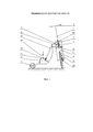
Суть изобретения поясняется фиг. 1, 2 и 3, на которых приведены:The essence of the invention is illustrated in FIG. 1, 2 and 3, which show:
на фиг. 1 - принципиальная схема индивидуального транспортного средства (возвратная пружина не показана);in FIG. 1 is a schematic diagram of an individual vehicle (return spring not shown);
на фиг. 2 - схема индивидуального транспортного средства (возвратная пружина не показана);in FIG. 2 is a diagram of an individual vehicle (return spring not shown);
на фиг. 3 - схема преобразования усилия в крутящий момент на направляющем колесе.in FIG. 3 is a diagram for converting force to torque on a steering wheel.
Индивидуальное транспортное средство включает в себя раму 1 с головной трубой 2, установленные на раме 1 опорное колесо 3 и рулевой механизм 4. Рулевой механизм 4 включает в себя руль 5, соединенный с вилкой 6 через рулевую колонку 7, корпусом которой является головная труба 2, установленное в вилку направляющее колесо 8 с механизмом привода 9. Механизм привода 9 снабжен барабаном 10, канатно-блочной трансмиссией 11, механизмом передачи усилия 12 с маятниковым рычагом 13 и кронштейнами 14. Причем маятниковый рычаг 13 с одной стороны закреплен на раме 1, а с другой стороны снабжен педалью 15. При этом кронштейны 14 установлены на рулевом механизме 4 со стороны торцов головной трубы 2. Для снижения необходимого количества деталей рулевой механизм 4 может быть выполнен на основе двухкоронной вилки, которая объединяет рулевой механизм 4 с кронштейнами 14 в одно целое. Канат 16 канатно-блочной трансмиссии 11 одним концом закреплен на одном из кронштейнов 14 и далее последовательно пропущен через обводной блок 17, установленный на головной трубе 2 и соосно с ней, через направляющие блоки на раме 1, количество и размещение которых зависит от выбора конкретных конструктивных решений при создании индивидуального транспортного средства. Далее канат 16 проходит через подвижный блок 18, размещенный на маятниковом рычаге 13, возвращается и вновь проходит через другие направляющие блоки, также размещенные на раме 1, через второй обводной блок 19, установленный соосно с головной трубой 2, и через направляющий блок 20 - на другом кронштейне 14, намотан и закреплен другим концом на барабане 10, который установлен на оси вращения направляющего колеса 8 и связан с ним через обгонную муфту 21, при этом барабан оснащен возвратной пружиной 22. Возвратная пружина 22 может быть выполнена спиральной, тогда ее можно поместить внутрь барабана 10. Механизм привода 9 направляющего колеса 8 может иметь дублирование. Второй механизм привода также снабжен барабаном, канатно-блочной трансмиссией, механизмом передачи усилия с маятниковым рычагом и кронштейнами. Причем маятниковый рычаг так же, как и в первом механизме привода 9, с одной стороны закреплен на раме 1, а с другой стороны снабжен педалью. При этом кронштейны могут быть использованы от первого механизма привода 9. Принцип работы второго механизма привода аналогичен первому. Варианты взаимного расположения других узлов и деталей двух механизмов привода зависят от конкретных конструктивных решений. Например, барабаны могут располагаться как по одну сторону от торца ступицы, так и по разные. Вариант размещения второго привода относительно осей симметрии рамы 1 позволит обеспечить максимальную взаимозаменяемость узлов и деталей приводов индивидуального транспортного средства. Наличие второго привода повысит надежность и динамику индивидуального транспортного средства.An individual vehicle includes a
Индивидуальное транспортное средство приводится в движение следующим образом. Пользователь переносит вес тела на ногу, установленную на педаль 15 маятникового рычага 13, поворачивает его вместе с подвижным блоком 18 канатно-блочной трансмиссии вниз, что сообщает канату 16 растягивающее усилие, которое раскручивает барабан 10 вследствие того, что другой конец каната 16 закреплен на кронштейне 14, установленном неподвижно на рулевом механизме 4. Крутящий момент от барабана 10 через обгонную (или храповую) муфту 21 передается на направляющее колесо 8, вследствие чего индивидуальное транспортное средство совершает поступательное движение по поверхности. После снятия нагрузки с педали 15 маятникового рычага 13, обгонная (или храповая) муфта 21 автоматически отключается от направляющего колеса 8, которое продолжает вращаться по инерции. Барабан 10 под воздействием возвратной пружины 22 сматывает канат 16 и возвращает педаль 15 маятникового рычага 13 с подвижным блоком 18 в исходное положение.An individual vehicle is driven as follows. The user transfers the weight of the body to the leg, mounted on the
Передаточное отношение регулируется за счет перемещения подвижного блока 18 вдоль маятникового рычага 13.The gear ratio is adjusted by moving the
Для улучшения динамики и увеличения надежности механизм привода 9 направляющего колеса 8 может дублироваться.To improve dynamics and increase reliability, the
Растягивающее усилие, возникающее при нажатии на педаль 15 маятникового рычага 13, направлено вдоль каната 16 и не изменяется по всей его длине. Канат 16 охватывает головную трубу 2 рамы 1 с противоположных сторон, проходя через обводные блоки 17 и 19 одинакового диаметра, установленные соосно на ней, и при растяжении производят два одинаковых по величине, но различные по направлению момента, которые компенсируют друг друга. На практике же, из-за трения в блоках, величины моментов могут не совпадать. В этом случае при езде на индивидуальном транспортном средстве пользователь будет ощущать некоторое незначительное усилие, стремящееся вывернуть руль в сторону. Для снижения влияния разности моментов на управляемость индивидуального транспортного средства, экспериментальным путем подбирается диаметр обводного блока 17 или 19. Для удобства хранения и эксплуатации рама 1 может быть выполнена складной, а конструкция рулевого механизма 4 и кронштейнов 14 может быть совмещена за счет ввода в конструкцию рулевого механизма на основе двухкоронной вилки.The tensile force that occurs when the
Индивидуальное транспортное средство лишено седла. По этой причине использование индивидуального транспортного средства предполагает постоянную опору пользователя на педали 15 (при дублировании механизма привода 9) и руль, что требует определенной физической подготовки для длительной езды. Данное решение позволяет снизить вес индивидуального транспортного средства и устранить прямое воздействие ударных нагрузок через таз на позвоночник пользователя.Individual vehicle devoid of a saddle. For this reason, the use of an individual vehicle involves constant support of the user on the pedals 15 (when duplicating the drive mechanism 9) and the steering wheel, which requires some physical preparation for a long ride. This solution allows you to reduce the weight of an individual vehicle and eliminate the direct impact of shock loads through the pelvis on the user's spine.
При традиционном размещении направляющего колеса в передней части транспортного средства эффект запаздывания поворота не проявляется. Также пропадает необходимость поворачивать руль в противоположную сторону от необходимого направления движения.With the traditional placement of the steering wheel in the front of the vehicle, the effect of the delay in turning does not occur. Also, there is no need to turn the steering wheel in the opposite direction from the desired direction of movement.
Применение каната 16 в качестве посредника для передачи усилия на барабан 10 позволяет удешевить и упростить конструкцию трансмиссии. Кроме того, канат 16, в отличие от цепной передачи, не требует периодической смазки в процессе эксплуатации, что упрощает эксплуатацию и исключает возможность случайного попадание смазки на одежду пользователя.The use of the
Размещение педалей не связано с величиной базы индивидуального транспортного средства. Таким образом, величина базы может варьироваться в зависимости от степени пересеченности преодолеваемой местности.The placement of the pedals is not related to the size of the base of an individual vehicle. Thus, the size of the base can vary depending on the degree of roughness of the overcome terrain.
И так, поставленная задача решена: индивидуальное транспортное средство получилось компактным, устойчивым к заносу, с хорошей управляемостью и со скоростными характеристиками на уровне существующих образцов с аналогичным приводом и диаметром ведущих колес.And so, the problem has been solved: the individual vehicle turned out to be compact, resistant to skidding, with good handling and with high-speed characteristics at the level of existing samples with the same drive and diameter of the driving wheels.
Claims (3)
Priority Applications (1)
| Application Number | Priority Date | Filing Date | Title |
|---|---|---|---|
| RU2016141303A RU2656802C2 (en) | 2016-10-20 | 2016-10-20 | Individual vehicle |
Applications Claiming Priority (1)
| Application Number | Priority Date | Filing Date | Title |
|---|---|---|---|
| RU2016141303A RU2656802C2 (en) | 2016-10-20 | 2016-10-20 | Individual vehicle |
Publications (2)
| Publication Number | Publication Date |
|---|---|
| RU2016141303A RU2016141303A (en) | 2018-04-20 |
| RU2656802C2 true RU2656802C2 (en) | 2018-06-06 |
Family
ID=61974528
Family Applications (1)
| Application Number | Title | Priority Date | Filing Date |
|---|---|---|---|
| RU2016141303A RU2656802C2 (en) | 2016-10-20 | 2016-10-20 | Individual vehicle |
Country Status (1)
| Country | Link |
|---|---|
| RU (1) | RU2656802C2 (en) |
Citations (3)
| Publication number | Priority date | Publication date | Assignee | Title |
|---|---|---|---|---|
| RU2379211C1 (en) * | 2008-06-17 | 2010-01-20 | Сергей Петрович Дашевский | All-wheel-drive bike |
| RU2434777C2 (en) * | 2009-12-30 | 2011-11-27 | Владимир Семёнович Белоенко | Pedal car |
| CN203946226U (en) * | 2014-07-07 | 2014-11-19 | 张晓敏 | Three-wheel bicycle pedal |
-
2016
- 2016-10-20 RU RU2016141303A patent/RU2656802C2/en active
Patent Citations (3)
| Publication number | Priority date | Publication date | Assignee | Title |
|---|---|---|---|---|
| RU2379211C1 (en) * | 2008-06-17 | 2010-01-20 | Сергей Петрович Дашевский | All-wheel-drive bike |
| RU2434777C2 (en) * | 2009-12-30 | 2011-11-27 | Владимир Семёнович Белоенко | Pedal car |
| CN203946226U (en) * | 2014-07-07 | 2014-11-19 | 张晓敏 | Three-wheel bicycle pedal |
Also Published As
| Publication number | Publication date |
|---|---|
| RU2016141303A (en) | 2018-04-20 |
Similar Documents
| Publication | Publication Date | Title |
|---|---|---|
| US4861054A (en) | Pedal-powered skateboard | |
| US4634137A (en) | Tricycle and drive therefor | |
| JP6186510B2 (en) | Improvements introduced in elliptical drive and steering mechanisms applicable to bicycles in general | |
| JP2010538902A (en) | Human powered vehicle with two reciprocating pedals | |
| US7481443B2 (en) | Vehicle with variable wheel camber | |
| CA2667906A1 (en) | Vehicle with three wheels | |
| CN104321245B (en) | The bicycle of drive component with uniqueness | |
| US6769706B2 (en) | Pedal powered scooter | |
| US4189166A (en) | Self-propelled vehicle | |
| WO2015020685A2 (en) | Frame for a human-powered vehicle | |
| CN103754316A (en) | Front and rear wheel dual-drive bicycle | |
| RU2656802C2 (en) | Individual vehicle | |
| WO2014190610A1 (en) | Spring and flywheel dual-energy storage balanced bicycle and man-power drive system | |
| CN109278917B (en) | Moment transmission mechanism and carrier | |
| RU2379211C1 (en) | All-wheel-drive bike | |
| KR20080093666A (en) | A bicycle by rear wheel steering, front wheel driving | |
| EP3655315B1 (en) | Pedal scooter | |
| JP7249046B2 (en) | bicycle propulsion device | |
| WO1998000331A1 (en) | Bicycle | |
| CN104354821A (en) | Multifunctional improved type bicycle capable of freeing two hands | |
| SU1838171A3 (en) | Velomobile | |
| RU78162U1 (en) | BICYCLE | |
| FI12179U1 (en) | Vehicle | |
| US20200223511A1 (en) | Pedal scooter | |
| Malppan et al. | A Review on Design Developments in Bicycle |