RU2655179C2 - Sliding door of the storage compartment of the vehicle - Google Patents
Sliding door of the storage compartment of the vehicle Download PDFInfo
- Publication number
- RU2655179C2 RU2655179C2 RU2014153655A RU2014153655A RU2655179C2 RU 2655179 C2 RU2655179 C2 RU 2655179C2 RU 2014153655 A RU2014153655 A RU 2014153655A RU 2014153655 A RU2014153655 A RU 2014153655A RU 2655179 C2 RU2655179 C2 RU 2655179C2
- Authority
- RU
- Russia
- Prior art keywords
- pair
- grooves
- panel
- door
- guide
- Prior art date
Links
Images
Classifications
-
- B—PERFORMING OPERATIONS; TRANSPORTING
- B60—VEHICLES IN GENERAL
- B60R—VEHICLES, VEHICLE FITTINGS, OR VEHICLE PARTS, NOT OTHERWISE PROVIDED FOR
- B60R11/00—Arrangements for holding or mounting articles, not otherwise provided for
- B60R11/06—Arrangements for holding or mounting articles, not otherwise provided for for tools or spare parts
-
- B—PERFORMING OPERATIONS; TRANSPORTING
- B60—VEHICLES IN GENERAL
- B60R—VEHICLES, VEHICLE FITTINGS, OR VEHICLE PARTS, NOT OTHERWISE PROVIDED FOR
- B60R7/00—Stowing or holding appliances inside vehicle primarily intended for personal property smaller than suit-cases, e.g. travelling articles, or maps
- B60R7/04—Stowing or holding appliances inside vehicle primarily intended for personal property smaller than suit-cases, e.g. travelling articles, or maps in driver or passenger space, e.g. using racks
Abstract
Description
Настоящее изобретение относится к вещевому отсеку (отсеку для хранения), устанавливаемому в центральной напольной консоли транспортного средства и имеющему сдвижную жесткую дверцу. В частности, настоящее изобретение относится к усовершенствованной конструкции жесткой сдвижной дверцы, которая в закрытом положении расположена заподлицо с сопряженными деталями центральной напольной консоли.The present invention relates to a storage compartment (storage compartment) mounted in a center floor console of a vehicle and having a sliding hard door. In particular, the present invention relates to an improved design of a rigid sliding door, which in the closed position is flush with the mating parts of the center floor console.
Центральные напольные консоли транспортных средств хорошо известны из уровня техники и зачастую включают в себя вещевой отсек, предназначенный для удобного хранения в нем предметов. Во многих подобных центральных напольных консолях установлена дверца или другая закрывающая конструкция, которая обеспечивает выборочное закрытие отверстия, образованного отсеком для хранения, для удержания предметов в отсеке для хранения, а также улучшения эстетического вида. В данных консолях дверца отсека для хранения может быть перемещена между закрытым положением, в котором доступ к отсеку для хранения невозможен, и открытым положением, в котором может быть осуществлен доступ к отсеку для хранения.The center floor consoles of vehicles are well known in the art and often include a storage compartment for convenient storage of items therein. Many such central floor consoles have a door or other closing structure that selectively closes the opening formed by the storage compartment to hold items in the storage compartment, as well as to improve the aesthetic appearance. In these consoles, the storage compartment door can be moved between a closed position in which access to the storage compartment is not possible and an open position in which access to the storage compartment can be made.
В некоторых примерах дверца отсека для хранения представляет собой жесткий элемент, способный перемещаться между закрытым и открытым положениями. В данных примерах жесткая дверца, как правило, перемещается между открытым и закрытым положениями по прямой линии. В результате стык заподлицо в соединении между концом дверцы и сопряженной панелью (ровная поверхность) на центральной консоли отсутствует. Хотя данная конструкция является эффективной, предпочтительно создать усовершенствованную конструкцию жесткой сдвижной дверцы, которая в закрытом положении будет расположена заподлицо с сопряженными деталями центральной напольной консоли.In some examples, the storage compartment door is a rigid member that can move between closed and open positions. In these examples, a rigid door typically moves between open and closed positions in a straight line. As a result, the joint is flush in the connection between the end of the door and the mating panel (flat surface) on the center console. Although this design is effective, it is preferable to create an improved design of a rigid sliding door, which in the closed position will be flush with the mating parts of the center floor console.
Настоящее изобретение относится к усовершенствованной конструкции жесткой сдвижной дверцы отсека для хранения, устанавливаемого в центральной напольной консоли транспортного средства, при этом данная жесткая сдвижная дверца в закрытом положении расположена заподлицо с сопряженными деталями центральной напольной консоли. Консоль транспортного средства включает в себя корпус с двумя боковыми панелями, которые образуют вещевой отсек, включающий в себя отверстие и верхнюю панель, которая проходит между двумя боковыми панелями, примыкающими к отверстию отсека для хранения. Жесткая дверца опирается на корпус для перемещения между закрытым положением, которое предотвращает доступ к отсеку, и открытым положением, которое обеспечивает доступ к отсеку. Жесткая дверца в закрытом положении расположена заподлицо с панелью. Жесткая дверца опирается на направляющую, которая, в свою очередь, опирается на корпус. Направляющая включает в себя первый конец, имеющий первую пару канавок, выполненных в нем, и второй конец, имеющий вторую пару канавок, выполненных в нем. Дверца имеет первую пару выступов, которые проходят, соответственно, в первую пару канавок, и вторую пару выступов, которые, соответственно, проходят во вторую пару канавок. Каждая канавка из первой пары проходит практически линейно, а каждая канавка из второй пары также проходит практически линейно, но имеет загиб в начале.The present invention relates to an improved design of a rigid sliding door of a storage compartment mounted in a center floor console of a vehicle, wherein this rigid sliding door in a closed position is flush with the mating parts of the central floor console. The vehicle console includes a housing with two side panels that form a storage compartment including an opening and a top panel that extends between two side panels adjacent to the opening of the storage compartment. The rigid door rests on the housing to move between a closed position that prevents access to the compartment and an open position that provides access to the compartment. The rigid door in the closed position is flush with the panel. The rigid door rests on a guide, which, in turn, rests on the housing. The guide includes a first end having a first pair of grooves made therein, and a second end having a second pair of grooves made therein. The door has a first pair of protrusions that extend into the first pair of grooves, respectively, and a second pair of protrusions that respectively extend into the second pair of grooves. Each groove from the first pair runs almost linearly, and each groove from the second pair also runs almost linearly, but has a bend at the beginning.
Таким образом, согласно первому объекту настоящего изобретения создана консоль транспортного средства, содержащая: корпус, включающий в себя панель, имеющую конец, и отсек, имеющий отверстие вблизи указанного конца панели; и жесткую дверцу, представляющую собой цельный жесткий элемент, опирающийся на корпус для скользящего перемещения между закрытым положением, в котором предотвращается доступ к отсеку, и открытым положением, в котором обеспечивается доступ к отсеку, причем конец жесткой дверцы в ее закрытом положении расположен заподлицо с указанным концом панели, а в открытом положении - отстоит от него и не расположен заподлицо с ним.Thus, according to a first aspect of the present invention, there is provided a vehicle console comprising: a housing including a panel having an end and a compartment having an opening near the specified end of the panel; and a rigid door, which is a one-piece rigid element resting on the housing for sliding movement between a closed position in which access to the compartment is prevented and an open position in which access to the compartment is provided, the end of the rigid door being flush with said the end of the panel, and in the open position, is separated from it and is not located flush with it.
Предпочтительно, корпус включает в себя пару боковых панелей, образующих вещевой отсек, причем панель представляет собой верхнюю панель, проходящую между парой боковых панелей, примыкающих к отверстию.Preferably, the housing includes a pair of side panels forming a storage compartment, the panel being a top panel extending between a pair of side panels adjacent to the hole.
Предпочтительно, жесткая дверца опирается на направляющую, опирающуюся на корпус.Preferably, the rigid door rests on a guide resting on the housing.
Предпочтительно, направляющая образует отверстие, имеющее практически такой же размер, что и отверстие, образованное вещевым отсеком.Preferably, the guide forms an opening having substantially the same size as the opening formed by the storage compartment.
Предпочтительно, направляющая имеет пару канавок, выполненных в нем, а дверца имеет пару выступов, проходящих в соответствующую пару канавок.Preferably, the guide has a pair of grooves made therein, and the door has a pair of protrusions extending into the corresponding pair of grooves.
Предпочтительно, каждая канавка проходит практически линейно.Preferably, each groove extends substantially linearly.
Предпочтительно, направляющая включает в себя первый конец, имеющий первую пару канавок, выполненных в нем, и второй конец, имеющий вторую пару канавок, выполненных в нем, а дверца имеет первую пару выступов, проходящих, соответственно, в первую пару канавок, и вторую пару выступов, проходящих, соответственно, во вторую пару канавок.Preferably, the guide includes a first end having a first pair of grooves made therein and a second end having a second pair of grooves made therein, and the door has a first pair of protrusions extending respectively into the first pair of grooves and the second pair protrusions passing, respectively, into the second pair of grooves.
Предпочтительно, каждая канавка из первой пары канавок проходит практически линейно.Preferably, each groove of the first pair of grooves extends almost linearly.
Предпочтительно, каждая канавка из второй пары канавок вначале имеет изгиб, а далее проходит практически линейно.Preferably, each groove of the second pair of grooves first has a bend, and then runs almost linearly.
Предпочтительно, жесткая дверца в ее закрытом положении располагается заподлицо с задним концом панели.Preferably, the rigid door in its closed position is flush with the rear end of the panel.
Предпочтительно, вторая пара канавок расположена внутри первой пары канавок.Preferably, the second pair of grooves is located inside the first pair of grooves.
Предпочтительно, первая пара канавок образована в боковых сторонах направляющей, которые образуют отверстие, а вторая пара канавок проходит под панелью.Preferably, the first pair of grooves is formed on the sides of the guide that form the hole, and the second pair of grooves extends beneath the panel.
Согласно второму объекту настоящего изобретения создана консоль транспортного средства, содержащая: корпус, включающий в себя панель и отсек, имеющий отверстие вблизи панели; и жесткую дверцу, опирающуюся на корпус для перемещения между закрытым положением, в котором предотвращается доступ к отсеку, и открытым положением, в котором обеспечивается доступ к отсеку, причем жесткая дверца в ее закрытом положении расположена заподлицо с панелью, а в открытом положении - не расположена заподлицо с ней, при этом жесткая дверца опирается на направляющую, направляющая опирается на корпус, направляющая включает в себя первый конец, имеющий первую пару канавок, выполненных в нем, и второй конец, имеющий вторую пару канавок, выполненных в нем, дверца имеет первую пару выступов, проходящих, соответственно, в первую пару канавок, и вторую пару выступов, проходящих, соответственно, во вторую пару канавок, и либо вторая пара канавок расположена внутри первой пары канавок, либо первая пара канавок образована в боковых сторонах направляющей, которые образуют отверстие, а вторая пара канавок проходит под панелью.According to a second aspect of the present invention, a vehicle console is provided, comprising: a housing including a panel and a compartment having an opening near the panel; and a rigid door resting on the housing for moving between a closed position in which access to the compartment is prevented and an open position in which access to the compartment is provided, wherein the rigid door is flush with the panel in its closed position and not in the open position flush with it, while the rigid door rests on the guide, the guide rests on the housing, the guide includes a first end having a first pair of grooves made in it, and a second end having a second pair of ditches made in it, the door has a first pair of protrusions extending respectively into the first pair of grooves and a second pair of protrusions extending respectively into the second pair of grooves, and either the second pair of grooves is located inside the first pair of grooves, or the first pair of grooves is formed on the sides of the rail, which form a hole, and a second pair of grooves passes under the panel.
Предпочтительно, корпус включает в себя пару боковых панелей, образующих вещевой отсек, причем панель представляет собой верхнюю панель, проходящую между парой боковых панелей, примыкающих к отверстию.Preferably, the housing includes a pair of side panels forming a storage compartment, the panel being a top panel extending between a pair of side panels adjacent to the hole.
Предпочтительно, направляющая образует отверстие, имеющее практически такой же размер, что и отверстие, образованное вещевым отсеком.Preferably, the guide forms an opening having substantially the same size as the opening formed by the storage compartment.
Предпочтительно, каждая канавка из первой пары канавок проходит практически линейно.Preferably, each groove of the first pair of grooves extends almost linearly.
Предпочтительно, каждая канавка из второй пары канавок вначале имеет изгиб, а далее проходит практически линейно.Preferably, each groove of the second pair of grooves first has a bend, and then runs almost linearly.
Предпочтительно, жесткая дверца в ее закрытом положении располагается заподлицо с задним концом панели.Preferably, the rigid door in its closed position is flush with the rear end of the panel.
Предпочтительно, вторая пара канавок расположена внутри первой пары канавок.Preferably, the second pair of grooves is located inside the first pair of grooves.
Предпочтительно, первая пара канавок образована в боковых сторонах направляющей, которые образуют отверстие, а вторая пара канавок проходит под панелью.Preferably, the first pair of grooves is formed on the sides of the guide that form the hole, and the second pair of grooves extends beneath the panel.
Различные аспекты настоящего изобретения станут очевидными для специалистов в данной области техники после ознакомления с нижеследующим подробным описанием предпочтительного варианта осуществления данного изобретения со ссылкой на сопроводительные чертежи, на которых:Various aspects of the present invention will become apparent to those skilled in the art upon review of the following detailed description of a preferred embodiment of the present invention with reference to the accompanying drawings, in which:
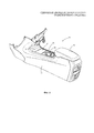
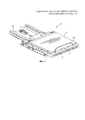
фиг. 1 - вид центральной напольной консоли транспортного средства, которая включает в себя узел сдвижной дверцы, соответствующий настоящему изобретению;FIG. 1 is a view of a center floor console of a vehicle that includes a sliding door assembly according to the present invention;
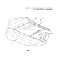
фиг. 2 - увеличенный общий вид части центральной напольной консоли с фиг. 1, на котором жесткая сдвижная дверца узла сдвижной дверцы изображена в закрытом положении;FIG. 2 is an enlarged general view of a portion of the center floor console of FIG. 1, wherein the rigid sliding door of the sliding door assembly is shown in the closed position;
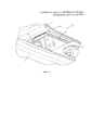
фиг. 3 - увеличенный общий вид, аналогичный виду с фиг. 3, на котором жесткая сдвижная дверца узла сдвижной дверцы изображена в открытом положении;FIG. 3 is an enlarged general view similar to that of FIG. 3, wherein the rigid sliding door of the sliding door assembly is shown in the open position;
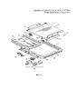
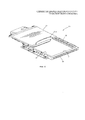
фиг. 4 - общий вид в разобранном виде узла сдвижной дверцы с фиг. 1 -3;FIG. 4 is an exploded perspective view of the sliding door assembly of FIG. 13;
фиг. 5 - увеличенный общий вид частей узла сдвижной дверцы, на котором жесткая сдвижная дверца изображена в закрытом положении;FIG. 5 is an enlarged general view of parts of a sliding door assembly, on which a rigid sliding door is shown in a closed position;
фиг. 6 - увеличенный общий вид, аналогичный виду с фиг. 5, на котором жесткая сдвижная дверца изображена в открытом положении;FIG. 6 is an enlarged general view similar to that of FIG. 5, in which a rigid sliding door is shown in the open position;
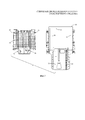
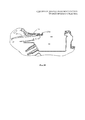
фиг. 7 - вид снизу частей узла сдвижной дверцы с фиг. 3-6;FIG. 7 is a bottom view of parts of the sliding door assembly of FIG. 3-6;
фиг. 8 - увеличенный боковой разрез частей узла сдвижной дверцы с фиг. 3-7;FIG. 8 is an enlarged side sectional view of parts of the sliding door assembly of FIG. 3-7;
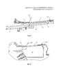
фиг. 9 - схематический вид вбок частей центральной напольной консоли, на котором жесткая сдвижная дверца изображена в закрытом положении; иFIG. 9 is a schematic side view of parts of a central floor console, in which a rigid sliding door is shown in a closed position; and
фиг. 10 - схематический вид вбок частей центральной напольной консоли, на котором жесткая сдвижная дверца изображена в открытом положении.FIG. 10 is a schematic side view of parts of a central floor console, in which a rigid sliding door is shown in an open position.
На фиг. 1 ссылочной позицией 10 обозначена центральная напольная консоль транспортного средства (не показано), соответствующая настоящему изобретению. Стандартные центральные напольные консоли для транспортных средств хорошо известны из уровня техники и зачастую включают в себя вещевой отсек (не показан на фиг. 1), предназначенный для удобного хранения в нем предметов. Хотя настоящее изобретение описано ниже на примере определенной центральной напольной консоли 10, изображенной на сопроводительных чертежах, следует понимать, что настоящее изобретение может быть осуществлено в виде консолей других типов, имеющих различные формы и конструкции.In FIG. 1,
Изображенная центральная напольная консоль 10 включает в себя корпус, состоящий из двух боковых панелей 11 и 12 и верхней панели 13, проходящей между двумя боковыми панелями 11 и 12. Изображенная центральная напольная консоль 10 также включает в себя держатель 14 для чашки и подлокотник 15, которые известны из уровня техники и не являются частью настоящего изобретения. Наконец, изображенной центральной напольной консоли 10 придана форма, имеющая внутреннее пространство, которое образует обычный отсек 16 для хранения (вещевой отсек). Отсек 16 для хранения предназначен для удобного хранения в нем предметов и имеет отверстие у верхнего конца отсека 16.The depicted
Узел сдвижной дверцы, обозначенный ссылочной позицией 20, предназначен для выборочного закрытия отверстия, образованного отсеком 16 для хранения, для помещения в него предметов и улучшения эстетического вида. Как более подробно описано ниже, узел 20 сдвижной дверцы включает в себя жесткую дверцу 21, которая перемещается между закрытым положением (показано на фиг. 2), в котором невозможен доступ в отсек 16 для хранения, и открытым положением (показано на фиг. 3), в котором может быть осуществлен доступ в отсек 16 для хранения.The sliding door assembly, indicated by
На фиг. 4 представлен общий вид в разобранном виде узла 20 сдвижной дверцы с фиг. 1-3. Как показано, дверца 21 узла 20 сдвижной дверцы имеет практически плоскую прямоугольную форму. Однако дверца 21 может иметь любые другие форму и размеры. Стандартная выступающая деталь 21а может быть расположена на дверце 21 (или объединена с дверцей 21) для облегчения захвата дверцы 21 пользователем и обеспечения перемещения между открытым и закрытым положениями, как будет сказано ниже. Дверца 21 имеет первую пару выступов 22, расположенных вбок рядом с первым концом дверцы 21. Дверца 21 имеет вторую пару выступов 23, расположенных вбок рядом со вторым концом дверцы 21. Первая и вторая пары выступов 22 и 23 более подробно представлены на фиг. 7. Назначение первой и второй пар выступов 22 и 23 разъяснено ниже.In FIG. 4 is an exploded perspective view of the sliding
Узел 20 сдвижной дверцы также включает в себя направляющую 30, на которую опирается дверца 21, причем направляющая 30, в свою очередь, опирается на центральную напольную консоль 10. Конструкция направляющей 30 показана на фиг. 4, 7 и 8. Изображенная направляющая 30 имеет первый конец с отверстием 31, образованным с его помощью. Отверстие 31 предпочтительно имеет размер и форму, соответствующие размеру и форме верхнего отверстия отсека 16 для хранения. Таким образом, когда направляющая 30 опирается на центральную напольную консоль 10, как показано на фиг. 1, 2 и 3, отверстие 31, образованное направляющей 30, имеет практически тот же размер (протяженность), что и верхнее отверстие вещевого отсека 16, хотя это не является обязательным условием. Первая пара канавок 32, расположенных друг напротив друга, находится на первом конце направляющей 30 с целью, описанной ниже. В представленном варианте осуществления изобретения первая пара канавок 32 расположена в боковых сторонах направляющей 30, которые ограничивают отверстие 31, хотя это не является обязательным условием. Направляющая 30 также имеет второй конец, проходящий в продольном направлении от первого конца. Вторая пара канавок 33, расположенных друг напротив друга, установлена аналогичным образом во втором конце направляющей 30 с целью, описанной ниже.The sliding
Как показано на фиг. 4, узел 20 сдвижной дверцы также может включать в себя различные другие компоненты, которые облегчают перемещение дверцы 21 относительно отсека 16 для хранения. Например, узел 20 сдвижной дверцы может включать в себя узел 40 пружины, инерционное блокирующее устройство 41, нажимно-вытяжную защелку 42 и вязкостный виброгаситель 43. Узел 40 пружины расположен между направляющей 30 и дверцей 21 таким образом, что при перемещении дверцы 21 оператором из закрытого положения в открытое положение энергия сохраняется на узле 40 пружины. При перемещении дверцы 21 в открытое положение может быть задействована нажимно-вытяжная защелка 42 для того, чтобы удержать дверцу 21 в данном открытом положении. После чего при необходимости перемещения дверцы 21 из открытого положения в закрытое положение нажимно-вытяжная защелка 42 может быть задействована для того, чтобы отпустить дверцу 21 и позволить энергии, накопленной на узле 40 пружины, автоматически переместить дверцу 21 из открытого положения обратно в закрытое положение. Инерционное блокирующее устройство 41 и вязкостный виброгаситель 43 установлены с целью предотвращения слишком быстрого перемещения дверцы 21 обратно из открытого положения в закрытое положение. Все данные компоненты хорошо известны из уровня техники и не являются частью настоящего изобретения.As shown in FIG. 4, the sliding
На фиг. 8, 9 и 10 показано, как дверца 21 взаимодействует с направляющей 30 в соответствии с настоящим изобретением. На фиг. 8 показан один выступ из первой пары выступов 22 на дверце 21, который проходит вбок и взаимодействует с соответствующей канавкой из первой пары канавок 32, расположенных друг напротив друга на первом конце направляющей 30. Хотя это не показано на фиг. 8, очевидно, что другой выступ из первой пары выступов 22 на дверце 21 проходит вбок и взаимодействует с соответствующей другой канавкой из первой пары канавок 32, расположенных друг напротив друга на первом конце направляющей 30. Таким образом, первый конец дверцы 21 (т.е. конец, прилегающий к первой паре выступов 22 и обозначенный как задний конец дверцы 21) опирается на первый конец направляющей 30 для обеспечения скольжения.In FIG. 8, 9 and 10 show how
Аналогичным образом на фиг. 8 также показан один выступ из второй пары выступов 23 на дверце 21, который проходит вбок и взаимодействует с соответствующей канавкой из второй пары канавок 33, расположенных друг напротив друга на втором конце направляющей 30. Хотя это не показано на фиг. 8, очевидно, что другой выступ из второй пары выступов 23 на дверце 21 проходит вбок и взаимодействует с соответствующей другой канавкой из второй пары канавок 33, расположенных друг напротив друга на втором конце направляющей 30. Таким образом, второй конец дверцы 21 (т.е. конец, прилегающий ко второй паре выступов 23 и обозначенный как передний конец дверцы 21) опирается на второй конец направляющей 30 для обеспечения скольжения.Similarly, in FIG. 8 also shows one protrusion from the second pair of
На фиг. 8 изображен пример геометрической формы первой пары канавок 32, расположенных друг напротив друга, и второй пары канавок 33, расположенных друг напротив друга в направляющей 30. Как показано на фиг. 8, первая пара канавок 32, расположенных друг напротив друга, проходит практически линейно от заднего конца (правая сторона фиг. 8) к переднему концу (левая сторона фиг. 8) узла 20 сдвижной дверцы. Как показано на фиг. 8, вторая пара канавок 33, расположенных друг напротив друга, вначале изгибается, а затем проходит практически линейно от заднего конца (правая сторона фиг. 8) к переднему концу (левая сторона фиг. 8) узла 20 сдвижной дверцы.In FIG. 8 shows an example of the geometric shape of the first pair of
На фиг. 8 и 9 показана дверца 21 в закрытом положении, в котором невозможен доступ к отсеку 16 для хранения. В данном закрытом положении передний конец дверцы 21 опирается на направляющую 30 таким образом, что передний конец дверцы 21 расположен заподлицо с задним концом верхней панели 13 центральной напольной консоли, как показано стрелкой 50 на фиг. 8 и 9. Данное выравнивание заподлицо переднего конца дверцы 21 с задним концом верхней панели 13 центральной напольной консоли 10 может быть достигнуто путем применения второй пары выступов 23 на дверце 21 и второй пары канавок 33, расположенных друг напротив друга, на втором конце направляющей 30 соответствующих размеров и форм. Данное выравнивание заподлицо важно для эстетических и прочих целей.In FIG. 8 and 9 show the
При перемещении дверцы 21 из закрытого положения (показано на фиг. 8 и 9) в открытое положение (показано на фиг. 10) первая пара выступов 22 проходит через первую пару канавок 32, расположенных друг напротив друга, от заднего конца к переднему концу узла 20 сдвижной дверцы. Аналогичным образом вторая пара выступов 23 также проходит через вторую пару противолежащих канавок 33 от заднего конца к переднему концу узла 20 сдвижной дверцы. Благодаря наличию изгиба в начале второй пары канавок 32, расположенных друг напротив друга, передний конец дверцы 21 сначала опускается вниз ниже заднего конца верхней панели 13 центральной напольной консоли 10. В результате дверца 21 поворачивается вокруг первой пары выступов 22 (против часовой стрелки, если смотреть на фиг. 8). Данный поворот дверцы 21 обеспечивает то, что передний конец дверцы 21 при его перемещении вперед под верхнюю панель 13 освобождает задний конец верхней панели 13 центральной напольной консоли 10. Данное перемещение вперед дверцы продолжается до тех пор, пока выступающая деталь 21 а не будет примыкать к заднему концу верхней панели 13 центральной напольной консоли 10 (как показано на фиг. 10), и нажимно-вытяжная защелка 42 не будет задействована для удержания дверцы 21 в данном открытом положении. При последующем задействовании нажимно-вытяжной защелки 42 для отпускания дверцы 21 данная дверца 21 перемещается назад до тех пор, пока она не установится в первоначальное закрытое положение, показанное на фиг. 8 и 9.When moving the
Принцип и режим работы, соответствующий настоящему изобретению, изложены и изображены со ссылкой на предпочтительный вариант осуществления. Однако следует понимать, что данное изобретение может быть применено на практике иным образом, чем указано в данном описании, без отступления от сущности и объема настоящего изобретения.The principle and mode of operation corresponding to the present invention are set forth and depicted with reference to a preferred embodiment. However, it should be understood that the invention may be practiced in a manner other than that described herein without departing from the spirit and scope of the present invention.
Claims (30)
Applications Claiming Priority (2)
| Application Number | Priority Date | Filing Date | Title |
|---|---|---|---|
| US14/151,002 US9199579B2 (en) | 2014-01-09 | 2014-01-09 | Sliding door for a storage bin in a vehicle center floor console |
| US14/151,002 | 2014-01-09 |
Publications (3)
| Publication Number | Publication Date |
|---|---|
| RU2014153655A RU2014153655A (en) | 2016-07-20 |
| RU2014153655A3 RU2014153655A3 (en) | 2018-03-22 |
| RU2655179C2 true RU2655179C2 (en) | 2018-05-24 |
Family
ID=53443250
Family Applications (1)
| Application Number | Title | Priority Date | Filing Date |
|---|---|---|---|
| RU2014153655A RU2655179C2 (en) | 2014-01-09 | 2014-12-29 | Sliding door of the storage compartment of the vehicle |
Country Status (6)
| Country | Link |
|---|---|
| US (1) | US9199579B2 (en) |
| CN (1) | CN104773115B (en) |
| BR (1) | BR102014031100A8 (en) |
| DE (1) | DE102014119362A1 (en) |
| MX (1) | MX360231B (en) |
| RU (1) | RU2655179C2 (en) |
Families Citing this family (27)
| Publication number | Priority date | Publication date | Assignee | Title |
|---|---|---|---|---|
| EP3105395A1 (en) * | 2014-02-12 | 2016-12-21 | Johnson Controls Technology Company | Latch assembly for a vehicle compartment door |
| JP1532155S (en) * | 2014-10-01 | 2017-08-14 | ||
| JP1532164S (en) * | 2014-11-12 | 2017-08-14 | ||
| JP1532168S (en) * | 2015-01-30 | 2018-08-20 | ||
| JP1537684S (en) * | 2015-02-10 | 2017-10-30 | ||
| USD770361S1 (en) * | 2015-02-11 | 2016-11-01 | Honda Motor Co., Ltd. | Center console |
| USD801899S1 (en) * | 2015-03-16 | 2017-11-07 | Jaguar Land Rover Limited | Door casing |
| JP1549100S (en) * | 2015-05-12 | 2017-05-01 | ||
| USD786174S1 (en) * | 2015-06-29 | 2017-05-09 | Dr. Ing. H.C.F. Porsche Aktiengesellschaft | Center console for a motor vehicle |
| JP1559957S (en) * | 2015-08-28 | 2018-09-18 | ||
| JP1543329S (en) * | 2015-08-28 | 2016-02-08 | ||
| JP1555995S (en) * | 2015-09-17 | 2017-07-31 | ||
| USD811988S1 (en) * | 2016-03-01 | 2018-03-06 | Bentley Motors Limited | Automobile console holder |
| USD784909S1 (en) * | 2016-03-01 | 2017-04-25 | Bentley Motors Limited | Automobile console |
| USD817257S1 (en) * | 2016-03-30 | 2018-05-08 | Tesla, Inc. | Vehicle display and mount |
| CN109070809B (en) | 2016-04-05 | 2022-06-24 | 上海延锋金桥汽车饰件系统有限公司 | Storage compartment for a vehicle interior |
| JP1567865S (en) * | 2016-06-10 | 2017-01-30 | ||
| CN105946729B (en) * | 2016-06-12 | 2018-07-03 | 浙江吉利控股集团有限公司 | Vehicle armrest box structure and automobile |
| USD804393S1 (en) * | 2016-06-15 | 2017-12-05 | Hyundai Mobis Co., Ltd. | Console for automobile |
| USD827540S1 (en) * | 2016-07-29 | 2018-09-04 | Nio Nextev Limited | Vehicle wheel rim |
| USD826838S1 (en) * | 2016-10-17 | 2018-08-28 | Jaguar Land Rover Limited | Center console |
| USD801911S1 (en) * | 2016-10-28 | 2017-11-07 | Remington Industries, Inc | Vehicle console kit |
| USD832187S1 (en) * | 2016-11-11 | 2018-10-30 | Jaguar Land Rover Limited | Split armrest and center console |
| USD824324S1 (en) * | 2017-04-05 | 2018-07-31 | Fca Us Llc | Automobile console |
| EP3492319B1 (en) * | 2017-11-29 | 2020-07-08 | Dr. Schneider Kunststoffwerke GmbH | Cover with a device for supporting the displacement |
| CN109572565B (en) * | 2018-12-04 | 2023-09-22 | 象山华杰塑业有限公司 | Automobile storage box assembly |
| USD922303S1 (en) * | 2018-12-19 | 2021-06-15 | Lg Electronics Inc. | Center console for automobile |
Citations (5)
| Publication number | Priority date | Publication date | Assignee | Title |
|---|---|---|---|---|
| US20030052129A1 (en) * | 2001-09-19 | 2003-03-20 | Nifco Inc. | Article storage device and shutter used therein |
| US20040206858A1 (en) * | 2001-06-19 | 2004-10-21 | Rockafellow Brent D | Adjustable armrest |
| US20090174208A1 (en) * | 2008-01-09 | 2009-07-09 | Toyota Motor Engineering & Manufacturing North America, Inc. | Motor Vehicle Center Console Assembly Having A Container Assembly With A Flush Door |
| US20110127791A1 (en) * | 2009-12-01 | 2011-06-02 | Toyota Motor Engineering & Manufacturing North America, Inc. | Console assembly |
| US20130134729A1 (en) * | 2011-11-29 | 2013-05-30 | Nissan North America, Inc. | Vehicle storage compartment assembly |
Family Cites Families (13)
| Publication number | Priority date | Publication date | Assignee | Title |
|---|---|---|---|---|
| US5657969A (en) * | 1994-12-29 | 1997-08-19 | Illinois Tool Works Inc. | Snap-in push-push latch mechanism |
| DE19611892C1 (en) * | 1996-03-26 | 1997-09-11 | Daimler Benz Ag | Central console for vehicle |
| DE19824248C2 (en) * | 1998-05-29 | 2001-10-18 | Carsten Lange | Cover for a shelf |
| US6203088B1 (en) * | 1999-01-19 | 2001-03-20 | Johnson Controls Technology Company' | Sliding console system |
| JP3731421B2 (en) * | 1999-12-24 | 2006-01-05 | 豊田合成株式会社 | Storage box |
| JP4467746B2 (en) * | 2000-09-11 | 2010-05-26 | 株式会社ニフコ | accessory case |
| US6419314B1 (en) * | 2001-01-05 | 2002-07-16 | Johnson Controls Technology Company | Vehicle accessory with sliding cover |
| US6547299B2 (en) * | 2001-09-19 | 2003-04-15 | Visteon Global Technologies, Inc. | Removable console |
| JP2003182462A (en) * | 2001-12-25 | 2003-07-03 | Moriroku Co Ltd | Vehicle console |
| US6616206B2 (en) * | 2002-01-04 | 2003-09-09 | Honda Giken Kogyo Kabushiki Kaisha | Center console assembly |
| US7168750B2 (en) | 2005-04-05 | 2007-01-30 | Lear Corporation | Rising hinge system for compartment lid |
| JP5247722B2 (en) | 2007-01-04 | 2013-07-24 | ジョンソン コントロールズ テクノロジー カンパニー | Integrated soft central floor console |
| JP5661350B2 (en) | 2009-08-27 | 2015-01-28 | 日本プラスト株式会社 | Vehicle storage device |
-
2014
- 2014-01-09 US US14/151,002 patent/US9199579B2/en active Active
- 2014-12-11 BR BR102014031100A patent/BR102014031100A8/en active Search and Examination
- 2014-12-22 DE DE102014119362.8A patent/DE102014119362A1/en active Pending
- 2014-12-29 RU RU2014153655A patent/RU2655179C2/en not_active IP Right Cessation
-
2015
- 2015-01-07 CN CN201510006809.XA patent/CN104773115B/en active Active
- 2015-01-09 MX MX2015000354A patent/MX360231B/en active IP Right Grant
Patent Citations (5)
| Publication number | Priority date | Publication date | Assignee | Title |
|---|---|---|---|---|
| US20040206858A1 (en) * | 2001-06-19 | 2004-10-21 | Rockafellow Brent D | Adjustable armrest |
| US20030052129A1 (en) * | 2001-09-19 | 2003-03-20 | Nifco Inc. | Article storage device and shutter used therein |
| US20090174208A1 (en) * | 2008-01-09 | 2009-07-09 | Toyota Motor Engineering & Manufacturing North America, Inc. | Motor Vehicle Center Console Assembly Having A Container Assembly With A Flush Door |
| US20110127791A1 (en) * | 2009-12-01 | 2011-06-02 | Toyota Motor Engineering & Manufacturing North America, Inc. | Console assembly |
| US20130134729A1 (en) * | 2011-11-29 | 2013-05-30 | Nissan North America, Inc. | Vehicle storage compartment assembly |
Also Published As
| Publication number | Publication date |
|---|---|
| BR102014031100A8 (en) | 2016-03-29 |
| MX2015000354A (en) | 2015-07-16 |
| MX360231B (en) | 2018-10-25 |
| DE102014119362A1 (en) | 2015-07-09 |
| US20150191125A1 (en) | 2015-07-09 |
| CN104773115A (en) | 2015-07-15 |
| US9199579B2 (en) | 2015-12-01 |
| BR102014031100A2 (en) | 2016-03-08 |
| RU2014153655A (en) | 2016-07-20 |
| RU2014153655A3 (en) | 2018-03-22 |
| CN104773115B (en) | 2018-09-18 |
Similar Documents
| Publication | Publication Date | Title |
|---|---|---|
| RU2655179C2 (en) | Sliding door of the storage compartment of the vehicle | |
| US8899703B2 (en) | Pressing-type unlocking track | |
| US8393663B2 (en) | Automobile glove compartment | |
| US8511765B1 (en) | Two way travel drawer slide | |
| US20140044382A1 (en) | Two way drawer slide | |
| RU2722606C2 (en) | Console chamber assembly for motor vehicle and method of supporting tray in storage compartment of console chamber assembly for motor vehicle | |
| JP2009062004A (en) | Armrest locking structure | |
| FR2988043A1 (en) | DEVICE FOR MOUNTING A CASE, IN PARTICULAR A RADIO, IN A DASH BOARD COMPARTMENT OF A MOTOR VEHICLE | |
| US20170057416A1 (en) | Vehicle center console assembly | |
| JP5728281B2 (en) | Locking device | |
| US9598885B2 (en) | Locking member, door stop, and rod locking system | |
| US8491028B2 (en) | Console sliding lid locator | |
| US8770680B1 (en) | Lock device for two-way travel drawer | |
| JP6576840B2 (en) | Cup holder | |
| US20070090243A1 (en) | Shelf shipping clip | |
| KR200411701Y1 (en) | Drawer type map pocket of car door | |
| JP6599611B2 (en) | Assembled storage furniture | |
| US1376493A (en) | Stop for extension-files | |
| KR102354150B1 (en) | Door cover support assembly structure of refrigerator | |
| KR101403165B1 (en) | Camping Trailer | |
| USRE21441E (en) | Panel pocket | |
| KR20150094857A (en) | Locking device of glove box for vehicle | |
| JP6271412B2 (en) | Thin slide cup holder | |
| JP2018118541A (en) | Vehicle back door and vehicle rear part structure | |
| KR200480879Y1 (en) | Handle for opening and closing furnitures |
Legal Events
| Date | Code | Title | Description |
|---|---|---|---|
| MM4A | The patent is invalid due to non-payment of fees |
Effective date: 20201230 |