RU2653760C2 - Eggs processing unit (options) and method of the eggs holding during their processing sequence (options) - Google Patents
Eggs processing unit (options) and method of the eggs holding during their processing sequence (options) Download PDFInfo
- Publication number
- RU2653760C2 RU2653760C2 RU2016136412A RU2016136412A RU2653760C2 RU 2653760 C2 RU2653760 C2 RU 2653760C2 RU 2016136412 A RU2016136412 A RU 2016136412A RU 2016136412 A RU2016136412 A RU 2016136412A RU 2653760 C2 RU2653760 C2 RU 2653760C2
- Authority
- RU
- Russia
- Prior art keywords
- egg
- eggs
- axis
- holding
- holding unit
- Prior art date
Links
Images


Classifications
-
- A—HUMAN NECESSITIES
- A01—AGRICULTURE; FORESTRY; ANIMAL HUSBANDRY; HUNTING; TRAPPING; FISHING
- A01K—ANIMAL HUSBANDRY; CARE OF BIRDS, FISHES, INSECTS; FISHING; REARING OR BREEDING ANIMALS, NOT OTHERWISE PROVIDED FOR; NEW BREEDS OF ANIMALS
- A01K45/00—Other aviculture appliances, e.g. devices for determining whether a bird is about to lay
- A01K45/007—Injecting or otherwise treating hatching eggs
-
- A—HUMAN NECESSITIES
- A01—AGRICULTURE; FORESTRY; ANIMAL HUSBANDRY; HUNTING; TRAPPING; FISHING
- A01K—ANIMAL HUSBANDRY; CARE OF BIRDS, FISHES, INSECTS; FISHING; REARING OR BREEDING ANIMALS, NOT OTHERWISE PROVIDED FOR; NEW BREEDS OF ANIMALS
- A01K41/00—Incubators for poultry
- A01K41/06—Egg-turning appliances for incubators
- A01K41/065—Egg drawers
-
- A—HUMAN NECESSITIES
- A01—AGRICULTURE; FORESTRY; ANIMAL HUSBANDRY; HUNTING; TRAPPING; FISHING
- A01K—ANIMAL HUSBANDRY; CARE OF BIRDS, FISHES, INSECTS; FISHING; REARING OR BREEDING ANIMALS, NOT OTHERWISE PROVIDED FOR; NEW BREEDS OF ANIMALS
- A01K43/00—Testing, sorting or cleaning eggs ; Conveying devices ; Pick-up devices
- A01K43/04—Grading eggs
-
- A—HUMAN NECESSITIES
- A01—AGRICULTURE; FORESTRY; ANIMAL HUSBANDRY; HUNTING; TRAPPING; FISHING
- A01K—ANIMAL HUSBANDRY; CARE OF BIRDS, FISHES, INSECTS; FISHING; REARING OR BREEDING ANIMALS, NOT OTHERWISE PROVIDED FOR; NEW BREEDS OF ANIMALS
- A01K45/00—Other aviculture appliances, e.g. devices for determining whether a bird is about to lay
-
- B—PERFORMING OPERATIONS; TRANSPORTING
- B65—CONVEYING; PACKING; STORING; HANDLING THIN OR FILAMENTARY MATERIAL
- B65D—CONTAINERS FOR STORAGE OR TRANSPORT OF ARTICLES OR MATERIALS, e.g. BAGS, BARRELS, BOTTLES, BOXES, CANS, CARTONS, CRATES, DRUMS, JARS, TANKS, HOPPERS, FORWARDING CONTAINERS; ACCESSORIES, CLOSURES, OR FITTINGS THEREFOR; PACKAGING ELEMENTS; PACKAGES
- B65D85/00—Containers, packaging elements or packages, specially adapted for particular articles or materials
- B65D85/30—Containers, packaging elements or packages, specially adapted for particular articles or materials for articles particularly sensitive to damage by shock or pressure
- B65D85/32—Containers, packaging elements or packages, specially adapted for particular articles or materials for articles particularly sensitive to damage by shock or pressure for eggs
Abstract
Description
ТЕХНИЧЕСКАЯ ОТРАСЛЬTECHNICAL INDUSTRY
Данное изобретение главным образом относится к установкам для обработки яиц. Точнее, данное изобретение относится к блоку для удерживания яиц, способному удерживать яйца, содержащиеся на платформе для яиц либо транспортере, во время обработки, и к соответствующей установке и способу.This invention mainly relates to installations for processing eggs. More specifically, the present invention relates to an egg holding unit capable of holding eggs contained on an egg platform or conveyor during processing, and to an appropriate apparatus and method.
УРОВЕНЬ ТЕХНИКИBACKGROUND
На фабрике для выращивания домашней птицы для обработки птичьих яиц используются разные механические установки для обработки яиц. Такие механические системы для обработки яиц могут содержать, например, установку для инъекции яиц для введения в яйцо лекарственной субстанции, установку для переноса яиц и установку для удаления выбранных яиц. Такие установки содержат множество отдельных обрабатывающих устройств (например, инъекционный инструмент, инструмент для удаления либо переноса яиц), традиционно разработанных для работы вместе с коммерческими устройствами для транспортировки яиц (так называемые "платформы"). Платформы для яиц, используемые вместе с такими установками, типично содержат массив карманов, которые выполнены для удержания соответствующего множества яиц главным образом в прямой либо вертикальной ориентации. Каждый карман может содержать множество лапок, которые выполнены для удержания соответствующего яйца. Хотя они и эффективны в удержании яиц во время транспортировки, эти несущие лапки могут повреждать яйца во время обработки отдельными обрабатывающими устройствами. Силы, прилагаемые к яйцу, в частности во время последовательности инъекции, могут толкать яйцо вниз к несущим лапкам с достаточной силой с вынуждением яиц трескаться. Как таковые, установки для обработки яиц могут использовать блок для удерживания яиц, способный предоставлять опору для яиц в яйцесборном транспортере во время последовательности обработки как те, что описаны в патенте US 6981470 (Gross et al.) либо международной публикации заявки №WO 2013/152970 (Van de Zande).The poultry farm uses various mechanical egg processing machines for processing poultry eggs. Such mechanical egg processing systems may include, for example, an egg injection unit for introducing a drug substance into an egg, an egg transfer unit, and a unit for removing selected eggs. Such plants contain many separate processing devices (for example, an injection tool, an egg removal or transfer tool), traditionally designed to work with commercial egg transport devices (so-called "platforms"). The egg platforms used in conjunction with such installations typically comprise an array of pockets that are designed to hold the corresponding plurality of eggs mainly in a straight or vertical orientation. Each pocket may contain many legs that are made to hold the corresponding egg. Although effective in holding eggs during transport, these support legs can damage eggs during processing by separate processing devices. The forces exerted on the egg, in particular during the injection sequence, can push the egg down to the supporting legs with sufficient force to cause the eggs to crack. As such, egg processing plants may use an egg holding unit capable of providing support for eggs in an egg collection conveyor during a processing sequence such as those described in US Pat. No. 6,981,470 (Gross et al.) Or International Publication No. WO 2013/152970 (Van de Zande).
Однако платформы для яиц и соответствующие их отдельные карманы выполняются во многих разных формах, с разными размерами и геометрическими формами в зависимости от производителя. Соответственно, блоки для удерживания яиц должны изготавливаться таким образом, чтобы их отдельные части (вставки либо подставки) (то есть части, контактирующие с яйцом) могли устанавливаться и подыматься/опускаться в отдельных карманах для контактирования и удержания яиц. В этом отношении вставки для удержания яиц должны изготавливаться для согласования со специальной формой платформы для яиц. На данный момент компания Zoetis LLC (правопреемник данной заявки) предоставляет более двадцати типов традиционных вставок для удерживания яиц, необходимых для согласования с разными формами платформ для яиц, используемые их потребителями. Такое изготовление блоков для удерживания яиц увеличивает денежные затраты на производство, поскольку механическая обработка деталей для удерживания яиц дешевле нежели процесс формования вследствие потребности малого объема, что делает процессы формования дорогими и нереалистическим вариантом производства. Такие модифицированные решения могут также предоставлять вставки для удерживания яиц, которые тяжело и длительно чистятся. Кроме того, сегодняшние блоки для удерживания яиц имеют приводные механизмы, которые могут расходовать чрезмерные количества энергии, обеспечивать неэффективность работы и дополнительные денежные затраты при использовании для подъема блока для удерживания яиц с вхождением в контакт с яйцами на платформе для яиц.However, egg platforms and their respective individual pockets are made in many different forms, with different sizes and geometric shapes depending on the manufacturer. Accordingly, the blocks for holding the eggs must be made in such a way that their separate parts (inserts or supports) (i.e., parts in contact with the egg) can be installed and raised / lowered in separate pockets for contacting and holding the eggs. In this regard, egg holding inserts should be made to align with the special shape of the egg platform. Currently, Zoetis LLC (assignee of this application) provides more than twenty types of traditional egg holding inserts needed to align with the various forms of egg platforms used by their consumers. Such manufacturing of egg holding blocks increases the cost of production, since machining parts for holding eggs is cheaper than the molding process due to the need for a small volume, which makes molding processes an expensive and unrealistic production option. Such modified solutions may also provide inserts for holding eggs that are difficult to clean for a long time. In addition, today's egg holding units have drive mechanisms that can consume excessive amounts of energy, provide inefficiencies and additional money costs when used to lift an egg holding unit that comes into contact with eggs on an egg platform.
Соответственно, должно быть желательным предоставить блок для удерживания яиц и соответствующую установку, способную удерживать яйца упрощенным и дешевым способом с одновременным облегчением технического обслуживания такого блока для удерживания яиц и установки, и дополнительным уменьшением модификации, связанной с этим. Кроме того, должно быть желательным предоставить соответствующий способ, который должен упростить и облегчить удерживание яиц во время обработки. Более того, должно быть желательным предоставить установку и соответствующий способ, способный предоставить улучшенный приводной механизм для блока для удержания яиц.Accordingly, it should be desirable to provide an egg holding unit and an appropriate installation capable of holding eggs in a simplified and cheap way while facilitating maintenance of such an egg holding unit and installation and further reducing the modification associated therewith. In addition, it should be desirable to provide an appropriate method, which should simplify and facilitate the retention of eggs during processing. Moreover, it should be desirable to provide an installation and an appropriate method capable of providing an improved drive mechanism for the egg holding unit.
КРАТКОЕ ОПИСАНИЕ ИЗОБРЕТЕНИЯSUMMARY OF THE INVENTION
Вышеупомянутые и другие требования выполняются данным изобретением, которое согласно одному аспекту предоставляет блок для удерживания яиц, имеющий плиту и множество подставок, функционально соединенных с плитой. Каждая подставка имеет множество отдельных элементов для удерживания яиц, объединяющихся для формирования гнезд для приема и контактирования с концом яйца для предоставления ему опоры.The above and other requirements are fulfilled by this invention, which according to one aspect provides an egg holding unit having a plate and a plurality of supports functionally connected to the plate. Each stand has many individual elements for holding eggs, combining to form nests for receiving and contacting the end of the egg to provide support.
Другой аспект предоставляет установку для обработки яиц, имеющую множество устройств для обработки яиц, выполненных для взаимодействия с множеством яиц, содержащихся в яйцесборном транспортере. Блок для удерживания яиц располагают под устройствами для обработки яиц и он имеет множество подставок. Каждая подставка имеет множество отдельных элементов, объединяющихся для формирования гнезда для контактирования и удерживания конца яйца в яйцесборном транспортере.Another aspect provides an egg processing apparatus having a plurality of egg processing apparatus configured to interact with a plurality of eggs contained in an egg collection conveyor. The egg holding unit is positioned underneath the egg processing apparatus and it has a plurality of supports. Each stand has many separate elements that combine to form a nest for contacting and holding the end of the egg in the egg collection conveyor.
Еще иной аспект предоставляет способ удерживания яиц во время последовательности их обработки. В способе располагают яйцесборный транспортер, содержащий множество яиц, под множеством устройств для обработки яиц, выполненных для взаимодействия с соответствующими яйцами в яйцесборном транспортере для их обработки. В способе дополнительно перемещают блок для удерживания яиц, расположенный под яйцесборным транспортером, в рабочее положение таким образом, что каждая из подставок контактирует и удерживает соответствующее яйцо в транспортере, при этом каждая подставка имеет множество отдельных элементов для удерживания яиц, объединяющихся для формирования гнезда для контактирования и удерживания конца соответствующего яйца в яйцесборном транспортере.Another aspect provides a method of holding eggs during the sequence of their processing. In the method, an egg collecting conveyor containing a plurality of eggs is arranged under a plurality of egg processing devices configured to interact with corresponding eggs in an egg collecting conveyor for processing them. In the method, the egg holding unit located under the egg collecting conveyor is additionally moved to the working position so that each of the stands contacts and holds the corresponding egg in the conveyor, with each stand having many separate elements for holding the eggs, which combine to form a contact nest and holding the end of the corresponding egg in the egg collection conveyor.
Еще иной аспект предоставляет установку для обработки яиц, имеющую множество устройств для обработки яиц, выполненных для взаимодействия с множеством яиц, содержащихся в яйцесборном транспортере. Блок для удерживания яиц располагают под устройствами для обработки яиц и он имеет множество подставок. Каждая подставка выполнена для контактирования и обеспечения опоры соответствующему яйцу в яйцесборном транспортере. Приводной блок выполнен для перемещения блока для удерживания яиц между рабочим положением и отведенным положением. Приводной блок имеет множество приводов и по меньшей мере один пандус, функционально соединенный с каждым приводом. Пандус способен передвигаться вдоль первой оси. Приводной блок дополнительно содержит множество подвижных элементов, функционально соединенных с блоком для удерживания яиц и выполненных для взаимодействия с соответствующим пандусом. Подвижные элементы способны передвигаться вдоль второй оси, не параллельной к первой оси, при этом движение пандусов вдоль первой оси вызывает движение подвижных элементов вдоль второй оси для облегчения движения блока для удерживания яиц между рабочим и отведенным положением.Another aspect is provided by an egg processing apparatus having a plurality of egg processing apparatus configured to interact with a plurality of eggs contained in an egg collection conveyor. The egg holding unit is positioned underneath the egg processing apparatus and it has a plurality of supports. Each stand is made for contacting and supporting the corresponding egg in the egg collection conveyor. The drive unit is designed to move the unit to hold the eggs between the working position and the retracted position. The drive unit has multiple drives and at least one ramp functionally connected to each drive. The ramp is able to move along the first axis. The drive unit further comprises a plurality of movable elements operably connected to the egg holding unit and configured to cooperate with a corresponding ramp. The movable elements are able to move along the second axis, not parallel to the first axis, while the movement of the ramps along the first axis causes the movement of the movable elements along the second axis to facilitate the movement of the block to hold the eggs between the working and the designated position.
Иной аспект предоставляет способ удерживания яиц во время последовательности их обработки. В способе располагают яйцесборный транспортер, содержащий множество яиц, под множеством устройств для обработки яиц, выполненных для взаимодействия с соответствующими яйцами в яйцесборном транспортере для их обработки. В способе дополнительно перемещают блок для удерживания яиц, расположенный под яйцесборным транспортером, в рабочее положение путем перемещения множества пандусов вдоль первой оси, используя множество приводов, таким образом вызывая взаимодействие и перемещение множества подвижных элементов вдоль второй оси, не параллельной к первой оси. Подвижные элементы функционально соединены с блоком для удерживания яиц таким образом, что их перемещение вдоль второй оси облегчает перемещение блока для удерживания яиц между рабочим положением и отведенным положением.Another aspect provides a method of holding eggs during the sequence of their processing. In the method, an egg collecting conveyor containing a plurality of eggs is arranged under a plurality of egg processing devices configured to interact with corresponding eggs in an egg collecting conveyor for processing them. In the method, the egg holding unit located under the egg collecting conveyor is additionally moved to a working position by moving a plurality of ramps along the first axis using a plurality of drives, thereby causing interaction and movement of the plurality of movable elements along a second axis that is not parallel to the first axis. The movable elements are operatively connected to the egg holding unit in such a way that their movement along the second axis facilitates the movement of the egg holding unit between the working position and the retracted position.
Таким образом, разные аспекты данного изобретения предоставляют преимущества, как здесь детализировано.Thus, various aspects of the present invention provide advantages, as detailed here.
КРАТКОЕ ОПИСАНИЕ ЧЕРТЕЖЕЙBRIEF DESCRIPTION OF THE DRAWINGS
Таким образом, описав в общих терминах разные варианты выполнения данного изобретения, теперь ссылка будет делаться на сопровождающие чертежи, которые не обязательно выполнены в масштабе, и на которых:Thus, having described in general terms various embodiments of the invention, reference will now be made to the accompanying drawings, which are not necessarily drawn to scale, and in which:
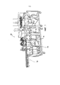
Фиг. 1 изображает вид в перспективе установки для инъекции яиц, имеющей блок для удерживания яиц, согласно одному аспекту данного изобретения;FIG. 1 is a perspective view of an egg injection apparatus having an egg holding unit, in accordance with one aspect of the present invention;
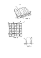
Фиг. 2 изображает вид в перспективе традиционной платформы для яиц;FIG. 2 is a perspective view of a conventional egg platform;
Фиг. 3 изображает вид сверху платформы для яиц с фиг. 2;FIG. 3 is a top view of the egg platform of FIG. 2;
Фиг. 4 изображает вид поперечного сечения платформы для яиц с фиг. 3, выполненного по линиям 4-4 и показывающий яйцо, удерживаемое в ее кармане;FIG. 4 is a cross-sectional view of the egg platform of FIG. 3, taken along lines 4-4 and showing an egg held in its pocket;
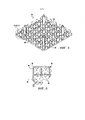
Фиг. 5 изображает вид в перспективе иной традиционной платформы для яиц;FIG. 5 is a perspective view of another conventional egg platform;
Фиг. 6 изображает вид сверху сечения платформы для яиц с фиг. 5;FIG. 6 is a top sectional view of the egg platform of FIG. 5;
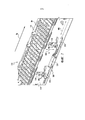
Фиг. 7 изображает частичный вид в перспективе конвейерного блока установки для обработки яиц согласно одному аспекту данного изобретения;FIG. 7 is a partial perspective view of a conveyor unit of an egg processing apparatus according to one aspect of the present invention;
Фиг. 8 изображает вид в перспективе конвейерного блока, взаимодействующего с блоком для удерживания яиц, согласно одному аспекту данного изобретения;FIG. 8 is a perspective view of a conveyor unit cooperating with an egg holding unit, in accordance with one aspect of the present invention;
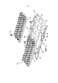
Фиг. 9 изображает схематический вид в частично разобранном состоянии блока для удерживания яиц и соответствующего приводного блока согласно одному аспекту данного изобретения;FIG. 9 is a partially exploded schematic view of an egg holding unit and corresponding drive unit in accordance with one aspect of the present invention;
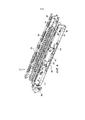
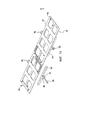
Фиг. 10 изображает схематический вид в перспективе плиты, имеющей множество подставок, выступающих из нее, согласно одному аспекту данного изобретения;FIG. 10 is a schematic perspective view of a plate having a plurality of supports protruding from it, in accordance with one aspect of the present invention;
Фиг. 11 изображает яйцо, удерживаемое подставкой блока для удерживания яиц, согласно одному аспекту данного изобретения;FIG. 11 depicts an egg held by a stand of an egg holding unit, in accordance with one aspect of the present invention;
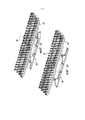
Фиг. 12 изображает схематический вид в перспективе множества отдельных элементов для удерживания яиц, объединяющихся для формирования гнезда для приема конца яйца, согласно одному аспекту данного изобретения;FIG. 12 is a schematic perspective view of a plurality of individual egg holding members integrating to form a nest for receiving an end of an egg, in accordance with one aspect of the present invention;
Фиг. 13 изображает схематический вид в перспективе множества отдельных элементов для удерживания яиц, объединяющихся для формирования каркасного гнезда для приема конца яйца, согласно одному аспекту данного изобретения;FIG. 13 is a schematic perspective view of a plurality of individual egg holding members integrating to form a frame nest for receiving the end of an egg, according to one aspect of the present invention;
Фиг. 14 изображает схематический вид в перспективе в частично разобранном состоянии рамы блока для удерживания яиц согласно одному аспекту данного изобретения;FIG. 14 is a schematic perspective view of a partially exploded state of the frame of an egg holding unit in accordance with one aspect of the present invention;
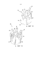
Фиг. 15 изображает схематический вид в перспективе блока для удерживания яиц, изображенного в отведенном положении, согласно одному аспекту данного изобретения;FIG. 15 is a schematic perspective view of an egg holding unit shown in a retracted position, in accordance with one aspect of the present invention;
Фиг. 16 изображает схематический вид в перспективе блока для удерживания яиц, изображенном в выдвинутом либо рабочем положении, согласно одному аспекту данного изобретения;FIG. 16 is a schematic perspective view of an egg holding unit shown in an extended or operational position, in accordance with one aspect of the present invention;
Фиг.17 изображает схематический вид в перспективе части приводного блока для блока для удерживания яиц согласно одному аспекту данного изобретения; и17 is a schematic perspective view of part of a drive unit for an egg holding unit according to one aspect of the present invention; and
Фиг. 18-23 изображают разные конфигурации подставок в соответствии с аспектами данного изобретения для согласования с разными конфигурациями платформы для яиц.FIG. 18-23 depict different configurations of stands in accordance with aspects of the present invention for matching with different configurations of the egg platform.
ДЕТАЛЬНОЕ ОПИСАНИЕ ИЗОБРЕТЕНИЯDETAILED DESCRIPTION OF THE INVENTION
Теперь более полно будут описываться разные аспекты данного изобретения со ссылкой на сопровождающие чертежи, на которых изображены некоторые, но не все аспекты изобретения. На самом деле, это изобретение может воплощаться во многих разных формах и не должно формулироваться как ограниченное изложенными здесь аспектами; скорее всего, эти аспекты предоставляются таким образом, что это изобретение будет удовлетворять используемые юридические требования. Одинаковые позиционные обозначения указывают везде одинаковые элементы.Now various aspects of the present invention will be more fully described with reference to the accompanying drawings, in which some, but not all aspects of the invention are depicted. In fact, this invention can be embodied in many different forms and should not be formulated as limited to the aspects set forth herein; most likely, these aspects are provided in such a way that this invention will satisfy the legal requirements used. The same reference numbers indicate the same elements everywhere.
Данное изобретение направлено на блоки, установки и способы удерживания яиц во время последовательности либо в случае обработки. Согласно некоторым аспектом данное изобретение предоставляет улучшенное несущее средство для удерживания яиц. Такие подтверждающие аспекты данного изобретения предоставляют много преимуществ, включая уменьшение усилий по модификации для принятия во внимание разных форм платформ для яиц, облегчение технического обслуживания и улучшение надежности.The present invention is directed to blocks, installations and methods for holding eggs during a sequence or in the case of processing. According to some aspect, the present invention provides an improved carrier for holding eggs. Such supportive aspects of the present invention provide many advantages, including reduced modification efforts to take into account the various forms of egg platforms, facilitated maintenance, and improved reliability.
Способы, блоки и установки согласно аспектам данного изобретения могут использоваться для инъекции яиц либо, иначе, для обработки яиц. Аспекты данного изобретения, однако, не ограничиваются установками для инъекции яиц, которые осуществляют инъекцию яиц, но могут применяться к любой системе обработки яиц, в которой желательно либо удерживать яйцо в платформе для яиц либо подымать яйцо с платформы для яиц. Например, описанное здесь средство для удерживания яиц может использоваться вместе с системой для удаления яиц для удаления яиц с платформы для яиц, при этом может быть желательным подымать яйца с платформы для яиц перед захватом яиц отдельными удаляющими устройствами системы для удаления яиц. Кроме того, аспекты данного изобретения могут выгодно подымать вертикально плиты, связанные с обработкой яиц, с одновременным сохранением плоскости, параллельной плоскости, определенной разными устройствами для обработки яиц.The methods, blocks, and plants according to aspects of the present invention can be used to inject eggs or, alternatively, to process eggs. Aspects of the present invention, however, are not limited to egg injection plants that inject eggs, but can be applied to any egg processing system in which it is desirable to either hold an egg in an egg platform or lift an egg from an egg platform. For example, the egg holding means described herein can be used in conjunction with an egg removal system for removing eggs from an egg platform, while it may be desirable to lift eggs from the egg platform before the eggs are captured by separate egg removal systems. In addition, aspects of the present invention can advantageously lift vertically the slabs associated with the processing of eggs, while maintaining a plane parallel to the plane defined by different egg processing devices.
Ссылаясь теперь на фиг. 1, видим, что здесь изображена иллюстративная установка для обработки яиц (например, установка 100 для инъекции яиц), содержащая блок для удерживания яиц. Изображенная установка 100 для инъекции яиц содержит каркас 110, который удерживает конвейерную систему 112 и множество устройств 25 для инъекции яиц со средствами подачи текучей субстанции, такими как иглы, расположенные в них, в соответствии с известными технологиями. Введение субстанций в яйца (а также экстрагирование материалов из яиц) типично осуществляется пробиванием скорлупы яйца для формирования отверстия (например, с помощью пробойника), введением инъекционной иглы сквозь отверстие во внутреннюю часть яйца (и в некоторых случаях в содержащийся в нем птичий эмбрион) и введением лекарственной(х) субстанции(й) сквозь иглу и/либо удалением из него материала. Например, каждое устройство 25 для инъекции яиц установки 100 может содержать пробойник и инъекционную иглу, при этом пробойник коаксиально охватывает иглу. Пробойник может формироваться для пробивания скорлупы яйца для формирования в ней отверстия, а игла может формироваться для введения субстанции в яйцо сквозь отверстие.Referring now to FIG. 1, we see that an illustrative egg processing apparatus (e.g., an egg injection apparatus 100) containing an egg holding unit is shown here. The illustrated
Платформы для яиц, используемые вместе с установкой 100, могут типично содержать массив карманов, которые сформированы для удержания соответствующего множества яиц главным образом в вертикальной ориентации. Указанная платформа 15 для яиц изображена на фиг. 2-4. Указанная платформа 15 для яиц содержит множество рядов карманов 32. Каждый карман 32 может формироваться для приема одного конца 17 соответствующего яйца 20 для удержания соответствующего яйца 20 в по существу вертикальном положении. Каждый карман 32 изображенной платформы 15 для яиц содержит множество лапок 34, которые сформированы для удерживания соответствующего яйца, как изображено на фиг. 4. Изображенная платформа 15 удерживает множество яиц 20 в по существу вертикальном положении и она сформирована для предоставления внешнего доступа к предварительно установленным участкам яиц 20. В частности, с каждым яйцом 20 можно контактировать сверху платформы 15 и снизу платформы 15. Каждое яйцо 20 удерживается изображенной платформой 15 таким образом, что его соответствующий конец находится в надлежащей ориентации относительно соответствующего одного из устройств 25 для инъекции яиц.The egg platforms used with the
Фиг. 5 и 6 изображают другую платформу 36 для яиц, которая может использоваться вместе с установкой 100. Платформа 36 для яиц отличается от платформы 15 для яиц, изображенной на фиг. 2-4. Каждый карман 38 платформы 36 для яиц, как определено лапками 40, сформирован по иному чем карманы 32 платформы 15 для яиц. Существует много типов и форм платформ для яиц, которые могут использоваться вместе с установкой 100. Причина наличия разных форм платформы для яиц в промышленности по выращиванию домашней птицы состоит в том, что производители инкубаторов типично имеют специальную платформу для яиц, которая формуется для работы со своим специально изготовленным оборудованием. Таким образом, производитель инкубатора диктует тип либо форму платформы для яиц, используемую в работе инкубаторной станции. Примеры соответствующих коммерческих платформ для яиц включают, но не ограничиваются платформой "CHICKMASTER 54", платформой"JAMESWAY 42" и платформой "JAMESWAY 84" (в каждом случае, номер указывает количество яиц, содержащихся в платформе). Соответственно, каждая платформа для яиц может требовать специального держателя яиц для удерживания либо подъема яиц, удерживаемых в платформе для яиц во время последовательности обработки либо в случае обработки, такой как, например, последовательность инъекции для введения лекарственной субстанции в яйцо.FIG. 5 and 6 depict another
Как изображено на фиг. 7, конвейерная система 112 может содержать пару по сути параллельных реек 114 и множество направляющих 116 между ними. Направляющие 116 могут выполняться для приема с помощью скольжения платформ 50 для яиц, расположенных на них, для перемещения в направлении, указанном стрелкой А1. Во время работы каждая платформа 50 для яиц может передвигаться в направлении A1 в положение непосредственно под устройства 25 для инъекции яиц либо другие обрабатывающие устройства таким образом, что множество яиц в платформе 50 для яиц могут подвергаться инъекции, удаляться либо иначе обрабатываться. В некоторых случаях конвейерная система 112 может содержать одну либо большее количество бесконечных лент 160, расположенных на и вдоль направляющих 116 и способных активироваться приводным двигателем 190 для транспортировки платформ 50 для яиц в направлении A1.As shown in FIG. 7, the
Согласно аспектам данного изобретения блок 130 для удерживания яиц может располагаться между рейками 114. Блок 130 для удерживания яиц может располагаться между рейками 114 таким образом, что платформы 50 для яиц проходят над ним. Фиг. 8 изображает вид в перспективе блока 130 для удерживания яиц, показывающий его расположение относительно реек 114 и направляющих 116. В некоторых случаях как изображено на фиг. 9, блок 130 для удерживания яиц может делиться на множество секций для предоставления ему возможности избегать взаимодействия с направляющими 116 при движении между рабочим положением (удерживая яйца) и отведенным положением (положение не удерживания, которое позволяет вертикальный зазор между блоком 130 для удерживания яиц и платформой 50 для яиц). Как будет описываться ниже, блок 130 для удерживания яиц может выполняться для удерживания либо подъема каждого яйца в платформе для яиц во время контакта устройством 25 для инъекции яиц либо другим обрабатывающим устройством.According to aspects of the present invention, an
Как изображено на фиг. 9-11, блок 130 для удерживания яиц может содержать одну либо большее количество плит 132, имеющих множество подставок 134, выступающих из верхней поверхности 133 плиты 132. Каждая подставка 134 может выполняться для удержания соответствующего яйца, как изображено, в частности, на фиг. 11, в платформе для яиц, расположенной сверху, как будет описываться ниже. В некоторых случаях подставка 134 может выполняться таким образом, что она обеспечивает полное удерживание яйца во время последовательности обработки. То есть подставка 134 может, в таких случаях подымать яйцо с платформы для яиц таким образом, что яйцо не контактирует с платформой для яиц. Подставки 134 могут устанавливаться на плите 132 с образованием структуры, согласующейся либо соответствующей массиву карманов в платформе для яиц.As shown in FIG. 9-11, the
Каждая подставка 134 может содержать множество элементов 135 для удерживания яиц, объединяющихся для формирования гнезда 136 для приема и контактирования с концом яйца для предоставления ему опоры. Элементы 135 для удержания яиц могут быть отдельными элементами для обеспечения разных расположений и конфигураций на плите 132 для предоставления возможности совместного согласования с разными формами платформ для яиц и их соответствующими карманами. Использование отдельных компонентов, которые могут устанавливаться в разных конфигурациях, устраняет трудоемкую модификацию, связанную с блоками для удерживания яиц предыдущего уровня техники. В этом отношении отдельные элементы 135 для удерживания яиц могут быть способными устанавливаться во множестве геометрических конфигураций относительно плиты 132. Для этого регулируемые отдельные элементы 135 для удерживания яиц предоставляют существенные преимущества по отношению к специально выполненным подставкам предыдущего уровня техники, поскольку лапки платформы для яиц ограничивают ширину либо периферию таких специально выполненных подставок предыдущего уровня техники. Предусматривая отдельные элементы 135 для удерживания яиц, эти элементы 135 могут располагаться либо позиционироваться между лапками, как изображено на фиг. 18-23, таким образом расширяя либо, иначе, увеличивая общее основание подставки 134 и гнезда 136. Такое увеличенное основание может облегчать доступ к яйцу, которое принимается в гнезде 136, что может быть особенно выгодно, когда удерживаемое яйцо отклоняется от вертикальной оси в кармане платформы для яиц.Each stand 134 may comprise a plurality of
Удаленный конец 137 подставки 134 может иметь вогнутую форму либо форму воронки, образованную наклоненными верхними частями 138 элементов 135 для удерживания яиц, которые сами по себе могут иметь радиальную часть. В некоторых случаях яйцо может полностью и целиком лежать в гнезде 136 подставки 134. Элементы 135 для удерживания яиц могут располагаться на расстоянии друг от друга под углом друг к другу.The
Согласно аспектам данного изобретения каждый отдельный элемент 135 для удерживания яиц, формирующий подставку 134, может быть формованной проволокой таким образом, что подставка 134 формируется из жесткой каркасной структуры, как изображено на фиг. 9, 10, 11 и 13. В других случаях, как изображено на фиг. 12, элементы 135 для удерживания яиц могут быть жесткими частями либо деталями, объединяющимися для формирования подставки 134 и гнезда 136. В некоторых случаях элементы 135 для удерживания яиц, формирующие подставку 134, могут быть по сути идентичными, в то время как в других случаях имеют разные формы. В любом случае элементы 135 для удерживания яиц могут конструироваться и выполняться таким образом, что предоставляют жесткую опору для яйца. В этом отношении элементы 135 для удерживания яиц могут формироваться из твердого материала либо конструкции. Такая жесткость может также обеспечивать подставке 134 и блоку 130 для удерживания яиц увеличенный термин эксплуатации. В других случаях, однако, элементы 135 для удерживания яиц могут формироваться из упругого материала, который предусматривает отклонение при приеме и контактировании с яйцом. Элементы 135 для удерживания яиц могут выполняться с любого материала, включая пластик и металлические материалы. В некоторых случаях элементы 135 для удерживания яиц могут выполняться с нержавеющей стали вследствие ее твердости и гигиенического качества.According to aspects of the present invention, each individual
Используя отдельные элементы 135 для удерживания яиц, подставка 134 может эффективно использоваться для приема разных форм платформы для яиц, существенно уменьшая денежные затраты, связанные с каждой подставкой 134. Например, предоставляя идентичные элементы 135 для удерживания яиц, изготовленные с твердой металлической проволоки, элементы 135 для удерживания яиц могут устанавливаться с прессовым соединением в плиту 132 в желаемой геометрической конфигурации для объединения с любым заданным типом платформы для яиц. В некоторых случаях в плите 132 могут предварительно высверливаться отверстия, которые позволяют устанавливать элементы 135 для удерживания яиц согласно многим схемам для согласования со многими формами платформы для яиц. В этом отношении элементы 135 для удерживания яиц могут легко и выгодно регулироваться для согласования с разными типами форм платформы для яиц.Using the individual
Фиг. 18-23 изображают разные варианты расположения элементов 135 для удерживания яиц для формирования подставок 134, способных принимать разные формы платформы 500 для яиц, имеющие лапки 502. Как изображено, количество элементов 135 для удерживания яиц, используемых для формирования подставок 134, может изменяться в зависимости от формы платформы 500 для яиц и/либо соответствующих лапок 502. Более того, в некоторых случаях элементы 135 для удерживания яиц могут устанавливаться в симметричной геометрической конфигурации, в то время как в других случаях элементы 135 для удерживания яиц могут устанавливаться с изменяемыми угловыми ориентациями относительно друг друга таким образом, что геометрическая структура является симметричной. В некоторых случаях геометрическое расположение элементов 135 для удерживания яиц может иметь много линий симметрии.FIG. 18-23 depict different arrangements of
Ссылаясь теперь на фиг. 7-9 и 14-17, видим, что плита(ы) 132 может/могут подвижно крепиться между рейками 114 с помощью подъемного устройства 150. Подъемное устройство 150 может содержать раму 152, проходящую между противоположными рейками 114 и множеством кронштейнов 154, соединенных либо прикрепленных к раме 152. Рама 152 может содержать множество ножек 156, которые вставляются в соответствующие отверстия, сформированные в плите/плитах 132 для прочного соединения рамы 152 и плиты/плит 132. Такая структура может облегчать удаление плит 132 для чистки и технического обслуживания.Referring now to FIG. 7-9 and 14-17, we see that the plate (s) 132 can / can be movably fastened between the
Приводной блок 300 может предусматриваться для перемещения блока 130 для удерживания яиц между рабочим и отведенным положением. В некоторых случаях приводной блок 300 может выполняться для перемещения подъемного устройства 150 таким образом, что блок 130 для удерживания яиц может передвигаться между рабочим и отведенным положением. Согласно одному аспекту кронштейны 154 могут иметь множество отверстий 155 таким образом, что приводной блок 300 может соединяться с подъемным устройством 150. Например, приводной блок 300 может содержать множество подвижных элементов 305, каждый из которых имеет соединитель 306, такой как, например, болт с буртиком, способный вставляться в отверстие 155. Однако в других случаях приводной блок 300 может непосредственно соединяться с рамой 152, а не с кронштейнами 154. Кроме того, рама 152 и кронштейны 154 могут формироваться как одно целое.A
Рама 152 может передвигаться между сцепленным (рабочим) положением и расцепленным (отведенным) положением с помощью приводов 170 приводного блока 300. Изображенные приводы управляются пневматически и принимают сжатый воздух с помощью сопел. Могут использоваться другие типы приводов, включая, но не ограничиваясь гидравлическими приводами, электромагнитными приводами, электронными приводами и так далее, и/либо их комбинациями. Аспекты данного изобретения не ограничиваются пневматическими приводами.The
Каждый привод 170 может передвигать один либо большее количество пандусов 310 назад и вперед вдоль первой оси 400. Пандусы 310 могут двигаться вдоль направляющего элемента 320, прикрепленного к одной из реек 114, как изображено на фиг. 7 и 8. Перемещение пандуса 310 может вынуждать соответствующий подвижной элемент 305 передвигаться вверх и вниз в пазе 118, сформированном в рейке 114, вдоль второй оси 450, по существу перпендикулярной либо ортогональной к первой оси 400. Хотя подвижный элемент 305 изображен движущимся вертикально в пазе 118, будет понятно, что подвижный элемент 305 и соответствующий паз 118 могут выполняться таким образом, что подвижный элемент 305 движется по любой оси, не параллельной относительно первой оси 400. То есть подвижный элемент 305 может передвигаться вдоль любой оси, не параллельной относительно первой оси 400, при этом одним из вариантов может быть перемещение подвижного элемента 305 вдоль оси, перпендикулярной к первой оси 400. Подвижный элемент 305 может иметь катящуюся часть 307, выполненную для вращения вокруг соединителя 306. Катящаяся часть 307 может контактировать с соответствующим пандусом 310.Each drive 170 can move one or
Фиг.15 изображает блок 130 для удерживания яиц в отведенном положении. Во время работы пандусы 310 могут активироваться для передвижения вдоль первой оси 400. Пандусы 310 взаимодействуют с катящимися частями 307 подвижных элементов 305 таким образом, что катящиеся части контактируют и катятся вдоль пандусов 310 для передвижения в пазе 118 вдоль второй оси 450. Когда катящаяся часть 307 поднимается на пандус 310, блок 130 для удерживания яиц может передвигаться в рабочее положение, как изображено на фиг. 16, для удержания яиц сверху в платформе для яиц. Для возвращения в отведенное положение приводы 170 вынуждают пандусы 310 передвигаться вдоль первой оси 400 в противоположном направлении, таким образом вынуждая катящуюся часть 307 двигаться вниз по пандусу 310, а соединитель 306 передвигаться вниз в пазе 118. Как таковая, рама 152 может опускаться таким образом, что блок 130 для удерживания яиц пребывает в отведенном положении, позволяя платформе для яиц проходить над ним. Катящаяся часть 307 может также скользящим образом сцепляться с пандусом 310 таким образом, что в некоторых случаях катящаяся часть 307 не катится, а вместо этого скользит вдоль пандуса 310. В некоторых случаях вместо катящейся части 307 может предусматриваться некатящийся скользящий элемент для сцепления с пандусом 310 для передвижения рамы 152 между рабочим и отведенным положением.15 shows a
Когда рама 152 передвигается в сцепленное положение, блок 130 для удерживания яиц, установленный на ней, может перемещаться вверх таким образом, что каждая подставка 134, прикрепленная к нему, входит в карман платформы для яиц и удерживает соответствующее яйцо во время последовательности инъекции яиц либо другой последовательности обработки. Согласно аспектам данного изобретения каждая подставка 134 может немного подымать каждое яйцо с платформы для яиц, хотя это не требуется.When the
Во время работы платформа 50 для яиц, содержащая множество яиц 20, передвигается по блоку 130 для удерживания яиц перед инъекцией устройствами 25 для инъекции яиц. Рама 152 блока 130 для удержания яиц может передвигаться вверх приводным блоком 300 таким образом, что плита 132, содержащая множество подставок 134, передвигается вверх, до сцепления каждой подставки 134 с соответствующим яйцом 20. Устройства 25 для инъекции яиц контактируют с яйцами, которые удерживаются подставками 134, формируют отверстие в их скорлупе и вводят предварительно установленную дозу лекарственной субстанции в (и/либо удаляют субстанцию из) яйцо сквозь отверстие. В некоторых случаях, таких как удаление яиц с платформы для яиц с помощью устройств для удаления яиц, может быть желательным поднять яйца с платформы для яиц, используя блок 130 для удерживания яиц данного изобретения таким образом, что платформа для яиц не взаимодействует с устройством для удаления яиц.During operation, the
Много модификаций и другие аспекты данного изобретения, изложенные здесь, придут в голову специалисту в этой отрасли, получая выигрыш от информации, представленной в вышеупомянутом описании и на соответствующих чертежах. Поэтому следует понимать, что данное изобретение не ограничивается специальными раскрытыми аспектами и что модификации и другие аспекты попадают в объем правовой защиты приложенной формулы изобретения. Хотя здесь используются специальные термины, они используются только в обобщенном и описательном смысле, а не для ограничения.Many modifications and other aspects of the present invention set forth herein will come to a person skilled in the art, benefiting from the information presented in the above description and the corresponding drawings. Therefore, it should be understood that the invention is not limited to the specific aspects disclosed and that modifications and other aspects fall within the scope of legal protection of the attached claims. Although specific terms are used here, they are used only in a generalized and descriptive sense, and not for limitation.
Claims (15)
Applications Claiming Priority (3)
| Application Number | Priority Date | Filing Date | Title |
|---|---|---|---|
| US201461970394P | 2014-03-26 | 2014-03-26 | |
| US61/970,394 | 2014-03-26 | ||
| PCT/US2015/020845 WO2015148175A1 (en) | 2014-03-26 | 2015-03-17 | Egg support assembly, and associated device and method |
Publications (3)
| Publication Number | Publication Date |
|---|---|
| RU2016136412A RU2016136412A (en) | 2018-03-15 |
| RU2016136412A3 RU2016136412A3 (en) | 2018-03-15 |
| RU2653760C2 true RU2653760C2 (en) | 2018-05-14 |
Family
ID=52814205
Family Applications (1)
| Application Number | Title | Priority Date | Filing Date |
|---|---|---|---|
| RU2016136412A RU2653760C2 (en) | 2014-03-26 | 2015-03-17 | Eggs processing unit (options) and method of the eggs holding during their processing sequence (options) |
Country Status (14)
| Country | Link |
|---|---|
| US (2) | US9894886B2 (en) |
| EP (1) | EP3122177B1 (en) |
| JP (1) | JP6499670B2 (en) |
| KR (1) | KR101884106B1 (en) |
| CN (2) | CN111357683B (en) |
| AU (1) | AU2015236620B2 (en) |
| BR (1) | BR112016020996B1 (en) |
| CA (1) | CA2940651C (en) |
| DK (1) | DK3122177T3 (en) |
| ES (1) | ES2717252T3 (en) |
| HU (1) | HUE043773T2 (en) |
| MX (2) | MX2016012468A (en) |
| RU (1) | RU2653760C2 (en) |
| WO (1) | WO2015148175A1 (en) |
Families Citing this family (12)
| Publication number | Priority date | Publication date | Assignee | Title |
|---|---|---|---|---|
| GB201205243D0 (en) | 2012-03-26 | 2012-05-09 | Kraft Foods R & D Inc | Packaging and method of opening |
| EP2649877A1 (en) * | 2012-04-13 | 2013-10-16 | Viscon B.V. | Device and system for processing of eggs, such as vaccination or a vacuum suction or grabber based pick up |
| GB2511559B (en) | 2013-03-07 | 2018-11-14 | Mondelez Uk R&D Ltd | Improved Packaging and Method of Forming Packaging |
| GB2511560B (en) | 2013-03-07 | 2018-11-14 | Mondelez Uk R&D Ltd | Improved Packaging and Method of Forming Packaging |
| CN111357683B (en) * | 2014-03-26 | 2022-07-26 | 硕腾服务有限责任公司 | Egg support assembly, and related apparatus and methods |
| US10285383B2 (en) * | 2015-07-21 | 2019-05-14 | Zoetis Services Llc | Egg orienting assembly, and associated system, device and method |
| ITUA20161681A1 (en) * | 2016-03-15 | 2017-09-15 | Best S R L | Egg tray for incubators with deformable housings |
| MY195942A (en) * | 2016-08-25 | 2023-02-27 | Boehringer Ingelheim Animal Health Usa Inc | Egg Candling And Relocation Apparatus for use with in Ovo Injection Machines |
| CN107232527A (en) * | 2017-08-01 | 2017-10-10 | 俞建翔 | A kind of egg stew in soy sauce production line and its method |
| CN107660721A (en) * | 2017-11-09 | 2018-02-06 | 安徽省卓创信息科技服务有限公司 | A kind of bag egg device that fresh-keeping material is wrapped up for lime-preserved egg |
| SG11202004433XA (en) * | 2017-11-21 | 2020-06-29 | Fulfil Solutions Inc | Product handling and packaging system |
| CN110432451B (en) * | 2019-07-20 | 2024-02-02 | 泰兴市立君机械设备有限公司 | Egg air chamber knocking device |
Citations (4)
| Publication number | Priority date | Publication date | Assignee | Title |
|---|---|---|---|---|
| US369753A (en) * | 1887-09-13 | Revolving egg-cabinet | ||
| SU23658A1 (en) * | 1928-06-01 | 1931-10-31 | Г.М. Завражин | Device for sorting eggs |
| RU2436295C1 (en) * | 2007-09-21 | 2011-12-20 | Пфайзер Инк. | Method and device for control of automatic removal of eggs |
| WO2013152970A2 (en) * | 2012-04-13 | 2013-10-17 | Viscon B.V. | Device and system for processing of eggs, such as vaccination or a vacuum suction or grabber based pick up |
Family Cites Families (74)
| Publication number | Priority date | Publication date | Assignee | Title |
|---|---|---|---|---|
| US540502A (en) * | 1895-06-04 | Egg-case | ||
| US1500939A (en) | 1923-03-20 | 1924-07-08 | David A Howell | Egg-crate unpacking and repacking apparatus |
| GB213788A (en) * | 1923-05-02 | 1924-04-10 | Edgar Alldridge | Improvements in egg-cups |
| GB241138A (en) * | 1925-06-26 | 1925-10-15 | Edgar Alldridge | Improvements in holders for carrying or supporting various articles |
| US2177595A (en) * | 1937-01-06 | 1939-10-24 | William Marten | Egg handling device |
| US2666665A (en) * | 1949-09-08 | 1954-01-19 | Roy S Whitcher | Device for handling eggs |
| US2792253A (en) * | 1953-04-27 | 1957-05-14 | George N Bliss | Egg lifter |
| US3147844A (en) * | 1963-04-17 | 1964-09-08 | Lathan Mfg Company | Object conveying and positioning apparatus |
| US3377989A (en) | 1966-08-08 | 1968-04-16 | American Cyanamid Co | Automatic egg inoculating unit |
| DE1481343C3 (en) * | 1967-01-07 | 1974-11-28 | Alois Dipl.-Ing. 4790 Paderborn Loedige | Lifting and lowering device |
| DD136821A1 (en) * | 1978-06-22 | 1979-08-01 | Christian Grueger | DRIVE FOR FOLDING KNIVES IN ARC MACHINES |
| SE416663B (en) * | 1979-04-11 | 1981-01-26 | Rodoverken Handelsbolaget Unde | LIFTING AND SHIFTING DEVICE FOR CISTERNER MANUFACTURING ACCORDING TO THE SCREW LINE METHOD |
| US4302142A (en) * | 1980-01-23 | 1981-11-24 | Kuhl Corporation | Apparatus for automatically loading eggs directly from stacks of egg-filled flats |
| US4593646A (en) | 1982-06-01 | 1986-06-10 | Agrimatic Corporation | Egg injection method and apparatus |
| US4524630A (en) * | 1983-09-29 | 1985-06-25 | Toth Leo A | Mechanical force amplifier |
| US4469047A (en) | 1983-10-25 | 1984-09-04 | Miller Gary E | Apparatus and method for injecting eggs |
| DE3441965A1 (en) * | 1984-11-16 | 1986-05-22 | Robert Bosch Gmbh, 7000 Stuttgart | DEVICE FOR LIFTING WORKPIECES AND WORKPIECE CARRIERS FROM A CONVEYOR |
| US4772001A (en) * | 1987-06-01 | 1988-09-20 | Hurdle Jr Ennis J | End log lifter |
| US4843958A (en) * | 1987-11-16 | 1989-07-04 | Ami International | Method and apparatus for applying advertisements to eggs |
| IT1229014B (en) * | 1989-04-14 | 1991-07-12 | Elba 2 S R L | EQUIPMENT FOR HANDLING GOODS ON INDUSTRIAL VEHICLES. |
| US5101954A (en) | 1989-12-15 | 1992-04-07 | Nambu Electric Co., Ltd. | Article conveying method and apparatus |
| US5158038A (en) | 1990-06-06 | 1992-10-27 | Sheeks Oliver B | Egg injection method, apparatus and carrier solution for improving hatchability and disease control |
| US5167317A (en) * | 1991-06-05 | 1992-12-01 | Fps Food Processing Systems B.V. | Apparatus for and method of transferring articles such as eggs |
| US5136979A (en) * | 1991-09-25 | 1992-08-11 | Embrex, Inc. | Modular injection system for avian embryos |
| US5242388A (en) * | 1992-01-21 | 1993-09-07 | Morf, Inc. | Inoculation system |
| US5620224A (en) * | 1994-09-26 | 1997-04-15 | Holiday Rambler Llc | Trailer slideout mechanism with vertically movable cabin floor |
| JPH08324981A (en) * | 1995-05-26 | 1996-12-10 | Matsuo Eng Kk | Multistep type wedge-shaped jack |
| US6345855B2 (en) * | 1996-11-27 | 2002-02-12 | Hwh Corporation | Level floor room extension |
| US5900929A (en) * | 1997-01-17 | 1999-05-04 | Embrex, Inc. | Method and apparatus for selectively injecting poultry eggs |
| US6240877B1 (en) * | 1997-01-27 | 2001-06-05 | Edward G. Bounds | Egg injection apparatus and method |
| US6287068B1 (en) * | 1998-12-21 | 2001-09-11 | Micron Technology, Inc. | Self-aligning tray carrier apparatus with tilt feature |
| US6244569B1 (en) * | 1998-12-21 | 2001-06-12 | Micron Electronics, Inc. | Controlled motion lift mechanism |
| US6149375A (en) * | 1999-03-18 | 2000-11-21 | Embrex, Inc. | Egg removal apparatus |
| US6234320B1 (en) * | 1999-05-11 | 2001-05-22 | Embrex, Inc. | Method and apparatus for selectively classifying poultry eggs |
| US6427305B1 (en) * | 1999-10-21 | 2002-08-06 | Ex-Cello Machine Tools, Inc. | Part elevator having a transfer bar with CAM follower and slot |
| GB0005121D0 (en) * | 2000-03-03 | 2000-04-26 | Future Alignments Limited | Separating device |
| JP3442357B2 (en) * | 2000-08-25 | 2003-09-02 | 株式会社日立製作所 | Amphibian oocyte sample introduction device, amphibian oocyte sample introduction system, amphibian oocyte sample introduction method, amphibian oocyte production method, amphibian oocyte and method of selling or transferring it, as sensor for screening Method used, container, and analysis method |
| US20030056729A1 (en) * | 2001-09-12 | 2003-03-27 | Correa Rafael S. | Automated egg injection machine and method |
| EP1362509B1 (en) | 2002-05-08 | 2005-02-02 | Sanovo Engineering A/S | An embryonated egg harvesting apparatus |
| US6981470B2 (en) * | 2003-01-27 | 2006-01-03 | Embrex, Inc. | Methods and apparatus for supporting eggs during in ovo injection |
| US7261053B2 (en) | 2004-04-03 | 2007-08-28 | Merial Limited | Methods and apparatus for automatic jet injection of bird eggs |
| BRMU8401284Y1 (en) | 2004-06-15 | 2016-03-08 | David Fredrick Smith | constructive arrangement introduced in automatic egg vaccinator |
| US7351019B2 (en) * | 2004-08-27 | 2008-04-01 | Custom Machine Manufacturing, Llc. | Clamping mechanism for an elongated workpiece |
| US7617795B2 (en) * | 2004-10-13 | 2009-11-17 | Embrex, Inc. | Methods and apparatus for injecting and sampling material through avian egg membranes |
| TWI297660B (en) * | 2004-11-29 | 2008-06-11 | Compact Automation Products Llc | Integrated pneumatic actuator and pump for dispensing controlled amounts of a fluid |
| EP1838146A4 (en) * | 2005-01-18 | 2009-06-03 | Embrex Inc | Methods and apparatus for detecting the presence of eggs in an egg flat |
| US7573566B2 (en) * | 2005-07-27 | 2009-08-11 | Embrex, Inc. | Methods and apparatus for maintaining effective operation of apparatus for candling avian eggs |
| BRMU8502383U (en) * | 2005-10-25 | 2007-07-24 | David Fredrick Smith | constructive arrangement introduced in automatic poultry vaccinator |
| US8201518B2 (en) * | 2006-04-16 | 2012-06-19 | David Fredrick Smith | Egg vaccination apparatus |
| BRMU8601558U (en) | 2006-04-17 | 2007-12-11 | David Fredrick Smith | constructive arrangement introduced in egg vaccinator |
| US7475770B1 (en) * | 2007-02-01 | 2009-01-13 | Honda Motor Co., Ltd. | Flexible conveyor carrier fixture for part transport and method of use thereof |
| FR2912600B1 (en) * | 2007-02-16 | 2010-03-12 | Ceva Sante Animale | METHOD AND SYSTEM FOR RETRIEVING AN EGG PLATE |
| JP5258232B2 (en) * | 2007-08-30 | 2013-08-07 | 株式会社ミマキエンジニアリング | Printing device |
| FR2920275B1 (en) * | 2007-08-30 | 2012-12-28 | Eg Chix Advanced Technologies | METHOD FOR INJECTING A TREATMENT SUBSTANCE IN EGGS AND CORRESPONDING INJECTION HEAD |
| DE202008000998U1 (en) * | 2008-01-23 | 2008-03-27 | Pfankuch Maschinen Gmbh | Device for opening a cover sheet or cover of a bound printing unit |
| US7958843B2 (en) * | 2008-01-23 | 2011-06-14 | Avitech, Llc | In-ovo injection machine with transversely movable egg tray assembly for manual egg transfer after injection |
| WO2009094204A1 (en) * | 2008-01-23 | 2009-07-30 | Avitech, Llc | Vibration mechanism for vertical egg alignment prior to in-ovo injection |
| CH699247A1 (en) * | 2008-07-29 | 2010-01-29 | Rotzinger Ag | -Feed device. |
| BRPI0901689A2 (en) * | 2009-05-12 | 2011-01-25 | Nelson Yamasaki | improvement applied to continuous egg grader |
| FR2956821B1 (en) * | 2010-02-26 | 2012-04-27 | Millipore Corp | DEVICE FOR SEPARATING A MEMBRANE FROM A SUPPORT |
| DE102010053396B4 (en) * | 2010-12-03 | 2014-12-24 | Airbus Defence and Space GmbH | Transmission of a control force |
| NL2007401C2 (en) * | 2011-09-12 | 2013-04-09 | Mapper Lithography Ip Bv | Assembly and a method for lifting a module of a lithography system in a vertical direction and a lithography system comprising such assembly. |
| EP2773188B1 (en) * | 2011-11-02 | 2018-11-14 | Zoetis Services LLC | Indexing system for an in ovo injection apparatus, and associated method |
| US20130140135A1 (en) * | 2011-12-02 | 2013-06-06 | Lian Hok Tan | Belt conveyor for conveying solar wafers during fabrication |
| US9332738B2 (en) * | 2012-06-05 | 2016-05-10 | Zoetis Services Llc | Processing system for transferring eggs, and associated method |
| RU2015104944A (en) * | 2012-07-16 | 2016-09-10 | Формулатрикс, Инк. | APPARATUS, METHOD AND LIQUID FEEDING SYSTEM |
| US9296596B2 (en) * | 2012-10-15 | 2016-03-29 | Cameron Lanning Cormack | Hybrid wedge jack/scissor lift lifting apparatus and method of operation thereof |
| JP6179127B2 (en) * | 2013-02-28 | 2017-08-16 | 富士電機株式会社 | Mobile drive unit |
| NL2011438C2 (en) | 2013-09-12 | 2015-03-16 | Viscon B V | DEVICE FOR MANIPULATION OF EGGS. |
| FR3010861B1 (en) | 2013-09-24 | 2015-10-02 | Egg Chick Automated Technologies | DEVICE FOR REORIENTATION OF AN EGG IN A PLATE ALVEOL |
| US9513270B2 (en) * | 2013-11-18 | 2016-12-06 | Zoetis Services Llc | Non-contact egg identification system for determining egg viability using transmission spectroscopy, and associated method |
| US9395346B2 (en) * | 2013-11-18 | 2016-07-19 | Zoetis Services Llc | Non-contact egg identification system for determining egg viability, and associated method |
| US9522808B2 (en) * | 2014-02-10 | 2016-12-20 | Zoetis Services Llc | Egg lifting device, and associated systems and methods |
| CN111357683B (en) * | 2014-03-26 | 2022-07-26 | 硕腾服务有限责任公司 | Egg support assembly, and related apparatus and methods |
-
2015
- 2015-03-17 CN CN202010060965.5A patent/CN111357683B/en active Active
- 2015-03-17 BR BR112016020996-6A patent/BR112016020996B1/en active IP Right Grant
- 2015-03-17 US US14/659,699 patent/US9894886B2/en active Active
- 2015-03-17 WO PCT/US2015/020845 patent/WO2015148175A1/en active Application Filing
- 2015-03-17 ES ES15714710T patent/ES2717252T3/en active Active
- 2015-03-17 KR KR1020167026142A patent/KR101884106B1/en active IP Right Grant
- 2015-03-17 RU RU2016136412A patent/RU2653760C2/en active
- 2015-03-17 JP JP2016555968A patent/JP6499670B2/en active Active
- 2015-03-17 CN CN201580014470.6A patent/CN106163298B/en active Active
- 2015-03-17 CA CA2940651A patent/CA2940651C/en active Active
- 2015-03-17 HU HUE15714710A patent/HUE043773T2/en unknown
- 2015-03-17 EP EP15714710.9A patent/EP3122177B1/en active Active
- 2015-03-17 DK DK15714710.9T patent/DK3122177T3/en active
- 2015-03-17 MX MX2016012468A patent/MX2016012468A/en unknown
- 2015-03-17 AU AU2015236620A patent/AU2015236620B2/en active Active
-
2016
- 2016-09-23 MX MX2020012724A patent/MX2020012724A/en unknown
-
2018
- 2018-01-08 US US15/864,226 patent/US10485224B2/en active Active
Patent Citations (4)
| Publication number | Priority date | Publication date | Assignee | Title |
|---|---|---|---|---|
| US369753A (en) * | 1887-09-13 | Revolving egg-cabinet | ||
| SU23658A1 (en) * | 1928-06-01 | 1931-10-31 | Г.М. Завражин | Device for sorting eggs |
| RU2436295C1 (en) * | 2007-09-21 | 2011-12-20 | Пфайзер Инк. | Method and device for control of automatic removal of eggs |
| WO2013152970A2 (en) * | 2012-04-13 | 2013-10-17 | Viscon B.V. | Device and system for processing of eggs, such as vaccination or a vacuum suction or grabber based pick up |
Also Published As
| Publication number | Publication date |
|---|---|
| JP6499670B2 (en) | 2019-04-10 |
| US20180125039A1 (en) | 2018-05-10 |
| AU2015236620B2 (en) | 2018-07-26 |
| JP2017510265A (en) | 2017-04-13 |
| EP3122177B1 (en) | 2019-01-30 |
| KR101884106B1 (en) | 2018-07-31 |
| US9894886B2 (en) | 2018-02-20 |
| US20150272085A1 (en) | 2015-10-01 |
| RU2016136412A (en) | 2018-03-15 |
| MX2020012724A (en) | 2021-02-18 |
| CA2940651C (en) | 2019-01-15 |
| MX2016012468A (en) | 2017-01-06 |
| DK3122177T3 (en) | 2019-04-01 |
| CN106163298B (en) | 2020-02-21 |
| HUE043773T2 (en) | 2019-09-30 |
| CA2940651A1 (en) | 2015-10-01 |
| US10485224B2 (en) | 2019-11-26 |
| ES2717252T3 (en) | 2019-06-20 |
| CN111357683B (en) | 2022-07-26 |
| CN106163298A (en) | 2016-11-23 |
| BR112016020996B1 (en) | 2020-08-04 |
| RU2016136412A3 (en) | 2018-03-15 |
| KR20160125464A (en) | 2016-10-31 |
| CN111357683A (en) | 2020-07-03 |
| AU2015236620A1 (en) | 2016-09-15 |
| WO2015148175A1 (en) | 2015-10-01 |
| EP3122177A1 (en) | 2017-02-01 |
Similar Documents
| Publication | Publication Date | Title |
|---|---|---|
| RU2653760C2 (en) | Eggs processing unit (options) and method of the eggs holding during their processing sequence (options) | |
| US6981470B2 (en) | Methods and apparatus for supporting eggs during in ovo injection | |
| JP2017510265A5 (en) | ||
| CN109484821B (en) | Automatic feeding system for material tray | |
| CN104470355B (en) | For processing device and the system of egg | |
| RU2638311C1 (en) | Lifting device for eggs and systems and methods related thereto | |
| US8783675B2 (en) | Apparatus having paired lifting members for separating stacked pallets | |
| JP7034147B2 (en) | Machine loading / unloading equipment, plate workpiece machining machines and workpiece supports of the machine, and loading and unloading methods of the machine. | |
| US20160207652A1 (en) | Device for Manipulation of Eggs | |
| US7958843B2 (en) | In-ovo injection machine with transversely movable egg tray assembly for manual egg transfer after injection | |
| RU2683893C2 (en) | Transporting device for lifting/lowering of containers | |
| DE112007003604B4 (en) | Device for transferring components | |
| KR101736031B1 (en) | Lifting unit of apparatus for cultivating mushroom | |
| US20210402441A1 (en) | Automated Systems For Use In Sorting Small Objects, And Related Methods | |
| US20140338610A1 (en) | Plant for handling live poultry in a slaughterhouse | |
| KR20100132757A (en) | Insert plate carrying device | |
| JPH10218120A (en) | Transferring and mounting equipment for fruit and vegetables | |
| EP1844923A3 (en) | Apparatus for moving and positioning objects, particularly objects such as panels for manufacturing furniture components or the like, to be laminated inside presses | |
| EP0956766B1 (en) | Method and apparatus for unloading crates from a container onto a transfer conveyor | |
| KR100541998B1 (en) | Apparatus for dividing devices formed on a substrate into a plurality of individual devices | |
| ITUD20120222A1 (en) | EQUIPMENT AND METHOD FOR TRANSPORTING TRAYS FOR CONTAINERS | |
| CN110733688A (en) | device packaging equipment | |
| TH61899B (en) | Cutting Pallet | |
| TH118342A (en) | Cutting Pallet |