RU2643778C1 - Synchronous generator in direct-drive wind turbine - Google Patents
Synchronous generator in direct-drive wind turbine Download PDFInfo
- Publication number
- RU2643778C1 RU2643778C1 RU2016133756A RU2016133756A RU2643778C1 RU 2643778 C1 RU2643778 C1 RU 2643778C1 RU 2016133756 A RU2016133756 A RU 2016133756A RU 2016133756 A RU2016133756 A RU 2016133756A RU 2643778 C1 RU2643778 C1 RU 2643778C1
- Authority
- RU
- Russia
- Prior art keywords
- stator
- segments
- winding
- grooves
- teeth
- Prior art date
Links
Images
Classifications
-
- H—ELECTRICITY
- H02—GENERATION; CONVERSION OR DISTRIBUTION OF ELECTRIC POWER
- H02K—DYNAMO-ELECTRIC MACHINES
- H02K1/00—Details of the magnetic circuit
- H02K1/06—Details of the magnetic circuit characterised by the shape, form or construction
- H02K1/12—Stationary parts of the magnetic circuit
- H02K1/16—Stator cores with slots for windings
-
- H—ELECTRICITY
- H02—GENERATION; CONVERSION OR DISTRIBUTION OF ELECTRIC POWER
- H02K—DYNAMO-ELECTRIC MACHINES
- H02K7/00—Arrangements for handling mechanical energy structurally associated with dynamo-electric machines, e.g. structural association with mechanical driving motors or auxiliary dynamo-electric machines
- H02K7/18—Structural association of electric generators with mechanical driving motors, e.g. with turbines
- H02K7/1807—Rotary generators
- H02K7/1823—Rotary generators structurally associated with turbines or similar engines
- H02K7/183—Rotary generators structurally associated with turbines or similar engines wherein the turbine is a wind turbine
- H02K7/1838—Generators mounted in a nacelle or similar structure of a horizontal axis wind turbine
-
- F—MECHANICAL ENGINEERING; LIGHTING; HEATING; WEAPONS; BLASTING
- F03—MACHINES OR ENGINES FOR LIQUIDS; WIND, SPRING, OR WEIGHT MOTORS; PRODUCING MECHANICAL POWER OR A REACTIVE PROPULSIVE THRUST, NOT OTHERWISE PROVIDED FOR
- F03D—WIND MOTORS
- F03D9/00—Adaptations of wind motors for special use; Combinations of wind motors with apparatus driven thereby; Wind motors specially adapted for installation in particular locations
- F03D9/20—Wind motors characterised by the driven apparatus
- F03D9/25—Wind motors characterised by the driven apparatus the apparatus being an electrical generator
-
- H—ELECTRICITY
- H02—GENERATION; CONVERSION OR DISTRIBUTION OF ELECTRIC POWER
- H02K—DYNAMO-ELECTRIC MACHINES
- H02K1/00—Details of the magnetic circuit
- H02K1/06—Details of the magnetic circuit characterised by the shape, form or construction
- H02K1/12—Stationary parts of the magnetic circuit
-
- H—ELECTRICITY
- H02—GENERATION; CONVERSION OR DISTRIBUTION OF ELECTRIC POWER
- H02K—DYNAMO-ELECTRIC MACHINES
- H02K1/00—Details of the magnetic circuit
- H02K1/06—Details of the magnetic circuit characterised by the shape, form or construction
- H02K1/12—Stationary parts of the magnetic circuit
- H02K1/14—Stator cores with salient poles
-
- H—ELECTRICITY
- H02—GENERATION; CONVERSION OR DISTRIBUTION OF ELECTRIC POWER
- H02K—DYNAMO-ELECTRIC MACHINES
- H02K1/00—Details of the magnetic circuit
- H02K1/06—Details of the magnetic circuit characterised by the shape, form or construction
- H02K1/12—Stationary parts of the magnetic circuit
- H02K1/16—Stator cores with slots for windings
- H02K1/165—Shape, form or location of the slots
-
- H—ELECTRICITY
- H02—GENERATION; CONVERSION OR DISTRIBUTION OF ELECTRIC POWER
- H02K—DYNAMO-ELECTRIC MACHINES
- H02K1/00—Details of the magnetic circuit
- H02K1/06—Details of the magnetic circuit characterised by the shape, form or construction
- H02K1/22—Rotating parts of the magnetic circuit
- H02K1/24—Rotor cores with salient poles ; Variable reluctance rotors
-
- H—ELECTRICITY
- H02—GENERATION; CONVERSION OR DISTRIBUTION OF ELECTRIC POWER
- H02K—DYNAMO-ELECTRIC MACHINES
- H02K11/00—Structural association of dynamo-electric machines with electric components or with devices for shielding, monitoring or protection
- H02K11/04—Structural association of dynamo-electric machines with electric components or with devices for shielding, monitoring or protection for rectification
- H02K11/049—Rectifiers associated with stationary parts, e.g. stator cores
-
- H—ELECTRICITY
- H02—GENERATION; CONVERSION OR DISTRIBUTION OF ELECTRIC POWER
- H02K—DYNAMO-ELECTRIC MACHINES
- H02K15/00—Methods or apparatus specially adapted for manufacturing, assembling, maintaining or repairing of dynamo-electric machines
- H02K15/02—Methods or apparatus specially adapted for manufacturing, assembling, maintaining or repairing of dynamo-electric machines of stator or rotor bodies
- H02K15/022—Methods or apparatus specially adapted for manufacturing, assembling, maintaining or repairing of dynamo-electric machines of stator or rotor bodies with salient poles or claw-shaped poles
-
- H—ELECTRICITY
- H02—GENERATION; CONVERSION OR DISTRIBUTION OF ELECTRIC POWER
- H02K—DYNAMO-ELECTRIC MACHINES
- H02K15/00—Methods or apparatus specially adapted for manufacturing, assembling, maintaining or repairing of dynamo-electric machines
- H02K15/02—Methods or apparatus specially adapted for manufacturing, assembling, maintaining or repairing of dynamo-electric machines of stator or rotor bodies
- H02K15/024—Methods or apparatus specially adapted for manufacturing, assembling, maintaining or repairing of dynamo-electric machines of stator or rotor bodies with slots
-
- H—ELECTRICITY
- H02—GENERATION; CONVERSION OR DISTRIBUTION OF ELECTRIC POWER
- H02K—DYNAMO-ELECTRIC MACHINES
- H02K19/00—Synchronous motors or generators
- H02K19/16—Synchronous generators
-
- H—ELECTRICITY
- H02—GENERATION; CONVERSION OR DISTRIBUTION OF ELECTRIC POWER
- H02K—DYNAMO-ELECTRIC MACHINES
- H02K29/00—Motors or generators having non-mechanical commutating devices, e.g. discharge tubes or semiconductor devices
- H02K29/03—Motors or generators having non-mechanical commutating devices, e.g. discharge tubes or semiconductor devices with a magnetic circuit specially adapted for avoiding torque ripples or self-starting problems
-
- H—ELECTRICITY
- H02—GENERATION; CONVERSION OR DISTRIBUTION OF ELECTRIC POWER
- H02K—DYNAMO-ELECTRIC MACHINES
- H02K3/00—Details of windings
- H02K3/04—Windings characterised by the conductor shape, form or construction, e.g. with bar conductors
- H02K3/28—Layout of windings or of connections between windings
-
- H—ELECTRICITY
- H02—GENERATION; CONVERSION OR DISTRIBUTION OF ELECTRIC POWER
- H02K—DYNAMO-ELECTRIC MACHINES
- H02K5/00—Casings; Enclosures; Supports
- H02K5/24—Casings; Enclosures; Supports specially adapted for suppression or reduction of noise or vibrations
-
- H—ELECTRICITY
- H02—GENERATION; CONVERSION OR DISTRIBUTION OF ELECTRIC POWER
- H02K—DYNAMO-ELECTRIC MACHINES
- H02K2213/00—Specific aspects, not otherwise provided for and not covered by codes H02K2201/00 - H02K2211/00
- H02K2213/03—Machines characterised by numerical values, ranges, mathematical expressions or similar information
-
- Y—GENERAL TAGGING OF NEW TECHNOLOGICAL DEVELOPMENTS; GENERAL TAGGING OF CROSS-SECTIONAL TECHNOLOGIES SPANNING OVER SEVERAL SECTIONS OF THE IPC; TECHNICAL SUBJECTS COVERED BY FORMER USPC CROSS-REFERENCE ART COLLECTIONS [XRACs] AND DIGESTS
- Y02—TECHNOLOGIES OR APPLICATIONS FOR MITIGATION OR ADAPTATION AGAINST CLIMATE CHANGE
- Y02E—REDUCTION OF GREENHOUSE GAS [GHG] EMISSIONS, RELATED TO ENERGY GENERATION, TRANSMISSION OR DISTRIBUTION
- Y02E10/00—Energy generation through renewable energy sources
- Y02E10/70—Wind energy
- Y02E10/72—Wind turbines with rotation axis in wind direction
Landscapes
- Engineering & Computer Science (AREA)
- Power Engineering (AREA)
- Life Sciences & Earth Sciences (AREA)
- Sustainable Energy (AREA)
- Sustainable Development (AREA)
- Manufacturing & Machinery (AREA)
- Chemical & Material Sciences (AREA)
- Combustion & Propulsion (AREA)
- Mechanical Engineering (AREA)
- General Engineering & Computer Science (AREA)
- Iron Core Of Rotating Electric Machines (AREA)
- Synchronous Machinery (AREA)
- Connection Of Motors, Electrical Generators, Mechanical Devices, And The Like (AREA)
- Windings For Motors And Generators (AREA)
- Wind Motors (AREA)
Abstract
Description
Настоящее изобретение относится к синхронному генератору, в частности, к многополюсному синхронному кольцевому генератору безредукторной ветровой турбины. Помимо этого, настоящее изобретение относится к набору пластин для формирования пакета статорных пластин для статора такого синхронного генератора и к соответствующему способу для формирования такого пакета пластин статора. Помимо этого, настоящее изобретение относится к ветровой турбине, содержащей синхронный генератор.The present invention relates to a synchronous generator, in particular, to a multi-pole synchronous ring generator of a direct-drive wind turbine. In addition, the present invention relates to a set of plates for forming a package of stator plates for a stator of such a synchronous generator, and to a corresponding method for forming such a package of stator plates. In addition, the present invention relates to a wind turbine comprising a synchronous generator.
Ветровые турбины являются общеизвестными и генерируют электрический ток из ветра посредством генератора. Современные безредукторные ветровые турбины зачастую имеют многополюсный синхронный кольцевой генератор с большим диаметром воздушного зазора. Диаметр воздушного зазора в этом случае составляет, по меньшей мере, 4 метра и, в общем, достигает почти до 5 метров. Собранные синхронные генераторы могут иметь диаметр воздушного зазора даже приблизительно 10 метров.Wind turbines are well known and generate electric current from the wind through a generator. Modern gearless wind turbines often have a multi-pole synchronous ring generator with a large diameter air gap. The diameter of the air gap in this case is at least 4 meters and, in general, reaches almost 5 meters. Assembled synchronous generators can have an air gap diameter of even approximately 10 meters.
В ходе работы ветровой турбины, т.е. рассматриваемого синхронного генератора, растет шум, который, вследствие крупной физической формы, также может достигать крупных резонансных корпусов, таких как, например, оболочка гондолы для гондолы, размещающей или, по меньшей мере, частично размещающей синхронный генератор. На основе своей функции, такие синхронные генераторы безредукторной ветровой турбины представляют собой очень медленно вращающиеся генераторы, которые вращаются с типичной частотой вращения приблизительно в 5-35 оборотов в минуту. Эта медленная частота вращения также может генерировать особые шумы, соответственно, в частности, по сравнению с генераторами, которые вращаются при 1500 или 3000 оборотов в минуту.During operation of a wind turbine, i.e. of the synchronous generator under consideration, noise grows, which, due to its large physical form, can also reach large resonant bodies, such as, for example, the shell of a nacelle for a nacelle accommodating or at least partially accommodating a synchronous generator. Based on their function, such synchronous generators of a direct-drive wind turbine are very slowly rotating generators that rotate at a typical speed of approximately 5-35 revolutions per minute. This slow speed can also generate particular noises, respectively, in particular, compared with generators that rotate at 1,500 or 3,000 rpm.
Такие синхронные генераторы безредукторных ветровых турбин, и в силу этого ветровые турбины, могут становиться постоянным раздражающим источником шума вследствие своей непрерывной работы. В настоящее время, особенно крупные современные ветровые турбины все чаще устанавливаются на большем расстоянии от населенных районов и работают в этих местах, так что шумы из ветровой турбины также являются менее раздражающим.Such synchronous generators of gearless wind turbines, and therefore wind turbines, can become a constant annoying source of noise due to their continuous operation. Currently, especially large modern wind turbines are increasingly installed at a greater distance from populated areas and work in these places, so the noise from the wind turbine is also less annoying.
Тем не менее, в силу установки на большем расстоянии, фактическая проблема роста шума не исключается в принципе, а по сути, только отодвигается.However, due to the installation at a greater distance, the actual problem of noise growth is not excluded in principle, but, in fact, only pushed back.
Следовательно, цель настоящего изобретения состоит в разрешении, по меньшей мере, одной из вышеуказанных проблем. В частности, должен уменьшаться рост шума синхронного генератора, как описано выше. Должно быть предложено, по меньшей мере, альтернативное решение относительно известных решений.Therefore, the aim of the present invention is to solve at least one of the above problems. In particular, the noise growth of the synchronous generator should be reduced, as described above. At least an alternative solution to known solutions should be proposed.
Немецкое патентное ведомство нашло следующие документы предшествующего уровня техники для приоритетной заявки в отношении настоящей PCT-заявки: US 6 321 439 B1, DE 10 2009 015 044 A1, WO 2011/128 095 A2, DE 103 40 114 A1, DE 10 2005 061 892 A1, US 2004/0 036 374 A1, DE 199 23 925 A1, DE 101 10 466 A1, US 4 315 171 A и DE 15 38 772 B2.The German Patent Office has found the following prior art documents for a priority application for this PCT application: US 6 321 439 B1, DE 10 2009 015 044 A1, WO 2011/128 095 A2, DE 103 40 114 A1, DE 10 2005 061 892 A1, US 2004/0 036 374 A1, DE 199 23 925 A1, DE 101 10 466 A1, US 4 315 171 A and DE 15 38 772 B2.
Согласно изобретению, предложен синхронный генератор по п. 1, в частности, многополюсный синхронный кольцевой генератор безредукторной ветровой турбины. Такой многополюсный синхронный кольцевой генератор безредукторной ветровой турбины имеет множество полюсов статора, в частности, по меньшей мере, 48 зубьев статора, зачастую даже значительно больше зубьев статора, к примеру, в частности, 96 зубьев статора или еще больше зубьев статора. Магнитно-активная область генератора, а именно, как ротор, который также может упоминаться в качестве якоря, так и статор, размещаются в кольцеобразной области вокруг оси вращения синхронного генератора. Таким образом, в частности, область 0, по меньшей мере, в 50 процентов радиуса воздушного зазора не содержит материалов, которые проводят электрический ток или электрическое поле синхронного генератора. В частности, эта внутренняя часть является полностью свободной и также в принципе может быть доступной. Зачастую, эта область также составляет более 0-50 процентов радиуса воздушного зазора, в частности, вплоть до 0-70 процентов или даже 0-80 процентов радиуса воздушного зазора. В зависимости от конструктивного решения, в этой внутренней области может предоставляться опорная конструкция, но эта опорная конструкция может аксиально смещаться в некоторых вариантах осуществления.According to the invention, a synchronous generator according to
Следовательно, синхронный генератор имеет ротор и статор. Ротор иногда упоминается в качестве якоря, чтобы также отличать его по формулировке от аэродинамического ротора ветровой турбины.Therefore, the synchronous generator has a rotor and a stator. The rotor is sometimes referred to as an anchor to also distinguish it in terms of wording from the aerodynamic rotor of a wind turbine.
Статор содержит зубья и пазы, размещаемые между ними. Пазы принимают обмотку статора или множество обмоток статора, так что обмотка статора за счет этого размещается через пазы и вокруг зубьев.The stator contains teeth and grooves placed between them. The grooves receive a stator winding or a plurality of stator windings, so that the stator winding is thereby placed through the grooves and around the teeth.
Статор разделен в окружном направлении на сегменты статора, причем каждый из них имеет множество зубьев и множество пазов, и, по меньшей мере, два сегмента статора, смещаются или чередуются относительно друг друга в окружном направлении. Все сегменты статора размещаются рядом друг с другом в окружном направлении и, кроме того, в частности, чередуются или смещаются относительно друг друга приблизительно на четверть ширины паза или другую абсолютную величину, а именно, таким образом, что пазы и зубья сегмента статора сменяются однородно в окружном направлении, и эта однородность прерывается при переходе к следующему смежному сегменту статора в силу размещения более широкого или более узкого паза, более широкого или более узкого зуба, либо дополнительно, возможно более узкого зуба, либо дополнительно, возможно более узкого паза, или исключения зуба. В принципе, переход также может быть реализован другим способом. Затем пазы и зубья снова сменяются однородно, в частности, в каждом случае с идентичной шириной паза или в каждом случае с идентичной шириной зуба, в следующем смежном сегменте статора.The stator is divided in a circumferential direction into stator segments, each of which has a plurality of teeth and a plurality of grooves, and at least two stator segments are displaced or alternate relative to each other in a circumferential direction. All stator segments are placed next to each other in a circumferential direction and, in addition, in particular, alternate or shift relative to each other by about a quarter of the groove width or other absolute value, namely, in such a way that the grooves and teeth of the stator segment are uniformly replaced circumferential direction, and this uniformity is interrupted when moving to the next adjacent stator segment due to the placement of a wider or narrower groove, a wider or narrower tooth, or additionally, possibly narrower th tooth, or additionally, possibly a narrower groove, or exclusion of the tooth. In principle, the transition can also be implemented in another way. Then the grooves and teeth are replaced uniformly again, in particular, in each case with the same groove width or in each case with the identical tooth width, in the next adjacent stator segment.
Как результат, полюса ротора или якоря, которые распределены полностью однородно в окружном направлении, в каждом случае достигают теперь зубьев или пазов сегментов статора, которые смещаются или чередуются относительно друг друга, не точно одновременно в ходе вращательного движения ротора, а раньше или позже за счет этого смещения или этого чередования. Следовательно, тогда как полюс ротора достигает зуба статора сегмента статора, соответствующий полюс ротора достигает зуба статора другого чередующегося или смещенного сегмента статора с небольшим сдвигом по времени. Как следствие, колебание, в частности, синусоидальные токи, которые немного сдвигаются относительно друг друга, формируются в этих сегментах статора, которые чередуются или смещаются относительно друг друга. Это, в свою очередь, приводит к способности, посредством этих токов, формирования гармоник с уменьшенной амплитудой при наложении. Аналогично, прямое наложение шумов идентичной частоты, но различной фазы также может приводить к общему уменьшению шума, в частности, уровня шума. Эти два описанных эффекта также могут взаимодействовать друг с другом таким образом, что могут быть использованы синергические эффекты, что может приводить к более явному уменьшению общего уровня шума.As a result, the poles of the rotor or anchor, which are distributed completely uniformly in the circumferential direction, in each case now reach the teeth or grooves of the stator segments, which are displaced or alternate relative to each other, not exactly simultaneously during the rotational movement of the rotor, but sooner or later due to this displacement or this alternation. Therefore, while the rotor pole reaches the stator tooth of the stator segment, the corresponding rotor pole reaches the stator tooth of another alternating or offset stator segment with a slight time shift. As a result, the oscillation, in particular, sinusoidal currents, which are slightly shifted relative to each other, are formed in these segments of the stator, which alternate or are shifted relative to each other. This, in turn, leads to the ability, through these currents, of the formation of harmonics with reduced amplitude when superimposed. Similarly, the direct overlap of noise of the same frequency, but of a different phase can also lead to an overall reduction in noise, in particular, noise level. These two described effects can also interact with each other in such a way that synergistic effects can be used, which can lead to a more pronounced reduction in the overall noise level.
Например, статор может быть разделен на четыре сегмента 1-4 статора, и каждый сегмент статора может иметь (это также упоминается только в качестве примера) в каждом случае 12 зубьев статора, так что в итоге статор содержит в сумме 48 зубьев, и в этом отношении должен получаться сравнительно меньший многополюсный синхронный кольцевой генератор безредукторной ветровой турбины. Первый и третий сегменты статора и в силу этого пазы и зубья этих сегментов статора должны смещаться или чередоваться относительно второго и четвертого сегментов статора, т.е. их пазов и зубьев, соответственно.For example, the stator can be divided into four segments 1-4 of the stator, and each stator segment can have (this is also mentioned only as an example) in each
Предпочтительно, по меньшей мере, один зуб формирует полюс статора, и, соответственно, два полюса статора формируют полюсную пару, которая концептуально используется в данном случае для простоты для полюсной пары статора. В принципе, полюс статора также может формироваться из множества зубьев или разделенного зуба, что в данном случае не имеет большого значения. В любом случае, относительно этого варианта осуществления, предлагается, что число полюсных пар каждого сегмента статора является кратным числом двух. В частности, число полюсных пар каждого сегмента статора является кратным числом шести. Такая конфигурация, в силу которой конкретно число полюсных пар каждого сегмента статора составляет, по меньшей мере, кратное число двух, обеспечивает предоставление обмоток деталей для каждого сегмента статора. Таким образом, каждый сегмент статора может иметь форму независимого генератора или независимого виртуального генератора, который в этом отношении делит только ротор с другими сегментами статора.Preferably, at least one tooth forms the stator pole, and accordingly, the two stator poles form a pole pair, which is conceptually used in this case for simplicity for the pole pair of the stator. In principle, the stator pole can also be formed of many teeth or a divided tooth, which in this case does not matter much. In any case, with respect to this embodiment, it is proposed that the number of pole pairs of each stator segment is a multiple of two. In particular, the number of pole pairs of each stator segment is a multiple of six. Such a configuration, by virtue of which a particular number of pole pairs of each stator segment is at least a multiple of two, provides windings of parts for each stator segment. Thus, each stator segment can be in the form of an independent generator or an independent virtual generator, which in this respect only shares the rotor with other segments of the stator.
Если число полюсных пар каждого сегмента является кратным числом шести, описанный независимый сегмент статора может содержать трехфазные обмотки, в частности, даже с двумя независимыми трехфазными обмотками. Обе трехфазных обмотки, соответственно, могут генерировать сигнал трехфазного тока, и сигналы трехфазного тока этих двух независимых трехфазных обмоток могут сдвигаться относительно друг друга. За счет этого улучшается выпрямление в нисходящем направлении. Сигнал тока также может просто упоминаться в качестве тока.If the number of pole pairs of each segment is a multiple of six, the described independent stator segment may contain three-phase windings, in particular even with two independent three-phase windings. Both three-phase windings, respectively, can generate a three-phase current signal, and the three-phase current signals of these two independent three-phase windings can be shifted relative to each other. Due to this, downward straightening is improved. The current signal may also simply be referred to as current.
Предпочтительно, предоставляются четыре сегмента статора, и сегменты статора группируются в две группы сегментов, имеющие по два сегмента статора. С этой целью, предлагается, что число полюсных пар каждой группы сегментов является кратным числом четырех. Как результат, каждый сегмент статора, как описано выше, может наматываться независимо, и одновременно сегменты статора могут предоставляться в принципе симметрично, так что, следовательно, в итоге все сегменты статора имеют равный размер, проще говоря, в каждом случае занимают квадрант. Если зуб исключен при переходе между двумя смежными сегментами статора, которые чередуются относительно друг друга, данный (исключенный) зуб все равно должен быть включен в вычисление. Другими словами, в данном случае должен присутствовать полюс статора без выделенного зуба или полюсная пара статора только с одним выделенным зубом. Тем не менее, эффект полюсной пары предоставляется посредством соответствующей секции обмотки, одного зуба и одного или более других зубьев.Preferably, four stator segments are provided, and the stator segments are grouped into two groups of segments having two stator segments each. To this end, it is proposed that the number of pole pairs of each group of segments is a multiple of four. As a result, each stator segment, as described above, can be wound independently, and at the same time, the stator segments can be provided symmetrically in principle, so that, as a result, all stator segments are of equal size, in other words, in each case they occupy a quadrant. If a tooth is excluded during the transition between two adjacent stator segments that alternate relative to each other, this (excluded) tooth should still be included in the calculation. In other words, in this case, there must be a stator pole without a tooth selected or a stator pole pair with only one tooth selected. However, the effect of the pole pair is provided through the corresponding section of the winding, one tooth and one or more other teeth.
Альтернативно, если число полюсных пар каждой группы сегментов не является кратным числом четырех, предлагается, что сегменты статора из группы сегментов имеют различные числа полюсных пар. Например, статор с 84 полюсными парами в сумме, т.е. конкретно с 168 зубьями, может быть разделен на две группы сегментов, имеющие по два сегмента статора. Сегменты статора этих двух групп сегментов сменяются между собой. Таким образом, каждая группа сегментов имеет два сегмента статора, и каждая группа сегментов имеет 42 полюсных пары и в этом случае, например, один сегмент статора с 24 полюсными парами и один сегмент статора с 18 полюсными парами.Alternatively, if the number of pole pairs of each group of segments is not a multiple of four, it is proposed that the stator segments from the group of segments have different numbers of pole pairs. For example, a stator with 84 pole pairs in total, i.e. specifically with 168 teeth, can be divided into two groups of segments having two stator segments. The stator segments of these two groups of segments are interchanged. Thus, each group of segments has two stator segments, and each group of segments has 42 pole pairs, and in this case, for example, one stator segment with 24 pole pairs and one stator segment with 18 pole pairs.
Для этого и других вариантов осуществления, предлагается, что каждая группа сегментов соединена в каждом случае с выпрямителем в форме B12-моста. В этом случае, каждая группа сегментов может наматываться таким образом, что она формирует две трехфазных системы в качестве выходного тока. Эти две трехфазных системы, которые в силу этого в результате формируют шесть различных фазных токов, выпрямляются посредством этого B12-моста. Следовательно, каждая фаза подается в ветвь этого B12-моста, который, известным способом, выпрямляет эту фазу с помощью двух диодов. Выпрямленный ток каждой из этих фаз предоставляется в общий промежуточный контур постоянного тока либо в другое устройство накопления постоянного напряжения или устройство накопления постоянного тока.For this and other embodiments, it is proposed that each group of segments is connected in each case to a rectifier in the form of a B12 bridge. In this case, each group of segments can be wound in such a way that it forms two three-phase systems as the output current. These two three-phase systems, which therefore form six different phase currents, are rectified by means of this B12 bridge. Therefore, each phase is fed into the branch of this B12 bridge, which, in a known manner, rectifies this phase using two diodes. The rectified current of each of these phases is provided to a common intermediate DC circuit or to another DC voltage storage device or DC storage device.
В силу того факта, что обе группы сегментов соединяются с B12-мостом, и обе группы сегментов формируют два трехфазных тока, которые выпрямляются, может достигаться выпрямленный полный сигнал с очень несущественными гармониками. Это достигается, в частности, в силу того факта, что, по меньшей мере, два сегмента статора, или две группы сегментов смещаются или чередуются относительно друг друга в окружном направлении. Как результат, шесть фаз одной группы сегментов еще раз сдвигаются относительно шести фаз другой группы сегментов таким образом, что их наложение в выпрямленном полном сигнале уменьшается и в силу этого приводит к максимально небольшому числу гармоник.Due to the fact that both groups of segments are connected to the B12 bridge, and both groups of segments form two three-phase currents that are rectified, a rectified full signal with very minor harmonics can be achieved. This is achieved, in particular, due to the fact that at least two stator segments, or two groups of segments are displaced or alternate relative to each other in the circumferential direction. As a result, the six phases of one group of segments are again shifted relative to the six phases of the other group of segments in such a way that their superposition in the rectified full signal is reduced and, as a result, leads to the smallest possible number of harmonics.
Предпочтительно, пазы и зубья в каждом случае одного сегмента статора размещаются равноотстоящим образом, и, по меньшей мере, два сегмента статора смещаются или чередуются относительно друг друга в окружном направлении таким образом, что смежные зубья смежных сегментов статора или смежные пазы смежных сегментов статора имеют другое расстояние друг от друга по сравнению со смежными зубьями или пазами идентичного сегмента статора. Пазы и зубья в силу этого в каждом случае размещаются равноотстоящим образом в своем сегменте статора, в частности, таким образом, что все пазы сегмента статора и, в частности, всего статора имеют идентичную ширину, т.е. протяженность в окружном направлении, за исключением пазов в переходной или контактной области между двумя смежными сегментами статора. Соответственно, все зубья сегмента статора или даже всего статора также имеют идентичную ширину, т.е. протяженность в окружном направлении, за исключением зубьев в переходной или контактной области между двумя смежными сегментами статора.Preferably, the grooves and teeth in each case of one stator segment are equally spaced, and at least two stator segments are displaced or alternate relative to each other in the circumferential direction so that adjacent teeth of adjacent stator segments or adjacent grooves of adjacent stator segments distance from each other compared with adjacent teeth or grooves of an identical stator segment. Therefore, the grooves and teeth are in each case equally spaced in their stator segment, in particular in such a way that all the grooves of the stator segment and, in particular, of the entire stator have an identical width, i.e. extension in the circumferential direction, with the exception of grooves in the transition or contact region between two adjacent stator segments. Accordingly, all the teeth of the stator segment or even the entire stator also have an identical width, i.e. extension in the circumferential direction, with the exception of teeth in the transition or contact region between two adjacent stator segments.
Следовательно, предложенная конфигурация статора соответствует статору с абсолютно однородными зубьями и пазами в окружном направлении, причем этот статор разделяется на сегменты статора, в частности, на четное число сегментов статора равного размера, и затем, в частности, каждый второй сегмент статора теоретически должен вращаться вокруг оси вращения генератора через пропорцию ширины зуба или ширины паза.Therefore, the proposed stator configuration corresponds to a stator with absolutely uniform teeth and grooves in the circumferential direction, this stator being divided into stator segments, in particular, an even number of stator segments of equal size, and then, in particular, every second stator segment should theoretically rotate around the axis of rotation of the generator through the proportion of the width of the tooth or the width of the groove.
В соответствии с вариантом осуществления, предложен синхронный генератор, содержащий статор, в котором первый и второй паз первого сегмента статора или первый и второй зуб первого сегмента статора имеют среднее расстояние относительно друг друга n*a. Переменная в этом случае обозначает среднее расстояние между двумя смежными пазами или зубьями первого сегмента статора. Следовательно, в данном случае описывается расстояние, например, между центром первого паза и центром второго паза либо центром первого зуба и центром второго зуба. Предпочтительно, оно является идентичным среднему числу каждого расстояния между смежными зубьями всего статора.According to an embodiment, there is provided a synchronous generator comprising a stator, in which the first and second groove of the first stator segment or the first and second tooth of the first stator segment have an average distance n * a relative to each other. The variable in this case denotes the average distance between two adjacent grooves or teeth of the first stator segment. Therefore, in this case, the distance, for example, between the center of the first groove and the center of the second groove or the center of the first tooth and the center of the second tooth is described. Preferably, it is identical to the average of each distance between adjacent teeth of the entire stator.
Переменная n является числом расстояний между пазами или расстояний между зубьями, т.е. числом, которое меньше числа пазов между рассматриваемыми первым и вторым пазом посредством на значение 1, или числом, которое меньше числа зубьев между рассматриваемыми первым и вторым зубьями на значение 1.The variable n is the number of distances between the grooves or the distances between the teeth, i.e. a number that is less than the number of grooves between the first and second grooves under consideration by a value of 1, or a number that is less than the number of teeth between the first and second teeth in question by a value of 1.
Расстояние между первым и дополнительным пазом, причем дополнительный паз расположен на втором сегменте статора, либо расстояние между первым зубом и дополнительным зубом, который расположен на втором сегменте статора, составляет n*a+v или n*a-v.The distance between the first and additional groove, with the additional groove located on the second segment of the stator, or the distance between the first tooth and the additional tooth, which is located on the second segment of the stator, is n * a + v or n * a-v.
В этом случае, переменная v обозначает смещение или чередование между первым и вторым сегментами статора. Данное чередование в этом отношении больше 0, но меньше среднего расстояния между пазами или среднего расстояния a между зубьями. То, прибавляется или вычитается это смещение v, зависит от того, является рассматриваемое смещение или чередование в случае двух сегментов статора таким, что упомянутые сегменты статора чередуются или смещаются в направлении друг друга, и в этом случае переменная v должна вычитаться, либо от того, смещаются они или чередуются в направлении друг от друга, и в этом случае переменная v должна прибавляться.In this case, the variable v denotes the offset or alternation between the first and second stator segments. This alternation in this respect is greater than 0, but less than the average distance between the grooves or the average distance a between the teeth. Whether this offset v is added or subtracted depends on whether the considered offset or alternation in the case of two stator segments is such that the said stator segments alternate or shift towards each other, in which case the variable v must be subtracted, or they shift or alternate in the direction from each other, and in this case the variable v must be added.
Следовательно, из этого формального описания можно видеть, что зубья или пазы сегмента статора разнесены друг от друга посредством n-кратного среднего расстояния, тогда как, кроме того, также смещение v должно прибавляться или вычитаться из следующего сегмента статора, который чередуется или смещается относительно него. В принципе, в этом отношении, также следует понимать, что смещение v и расстояние a между пазами или расстояние a между зубьями означает расстояние вдоль окружности, либо означает угол на основе оси вращения генератора и в силу этого середины оси статора.Therefore, from this formal description it can be seen that the teeth or grooves of the stator segment are spaced apart from each other by an n-fold average distance, while, in addition, the offset v must also be added or subtracted from the next stator segment, which alternates or shifts relative to it . In principle, in this regard, it should also be understood that the displacement v and the distance a between the grooves or the distance a between the teeth means the distance along the circumference, or means the angle based on the axis of rotation of the generator and, therefore, the middle of the stator axis.
Предпочтительно, смещение или чередование имеет значение в 0,4-0,6 от расстояний между пазами или расстояний a между зубьями. В частности, смещение составляет приблизительно половину такого расстояния между пазами или расстояния a между зубьями. Как результат, шумы и/или токи, сгенерированные в соответствующих сегментах статора, имеют такой сдвиг фаз относительно соответствующих шумов или токов, что рост шума, получающийся в результате во всем синхронном генераторе, является максимально возможно низким. Это достигается, в частности, посредством предпочтительного наложения рассматриваемых компонентов, которые за счет этого уменьшают друг друга.Preferably, the offset or alternation has a value of 0.4-0.6 from the distance between the grooves or the distance a between the teeth. In particular, the offset is approximately half that distance between the grooves or the distance a between the teeth. As a result, the noise and / or currents generated in the respective stator segments have such a phase shift relative to the corresponding noise or currents that the noise growth resulting from the entire synchronous generator is as low as possible. This is achieved, in particular, through the preferred overlap of the components in question, which thereby reduce each other.
Предпочтительно, каждый сегмент статора принимает часть обмотки статора или обмоток статора в качестве сегмента обмотки, и сегменты обмотки несмежных сегментов статора соединяются между собой. Как результат, в дополнение к механическому чередованию или механическому смещению сегментов статора, также предоставляется соответствующее электрическое чередование. Это осуществляется, в частности, таким образом, что несмежные сегменты статора, т.е., в частности, каждый второй сегмент статора, соединяются друг с другом, т.е., в частности, в параллельной схеме или в последовательной схеме. Эти сегменты статора генерируют ток с идентичной частотой и фазовым углом в своих сегментах обмотки. Другие сегменты статора, размещаемые между этими несмежными сегментами статора и в силу этого сегментами статора, которые аналогично являются несмежными относительно друг друга, т.е. в принципе вторая группа несмежных сегментов статора, аналогично соединяются между собой и вместе генерируют ток с идентичной частотой и фазовым углом. В этом случае, обычно присутствует трехфазный ток, который также прикладывается к соответствующей первой группе несмежных сегментов статора. Предпочтительно, чередование выполняется в каждом случае в качестве последовательной схемы, так что в итоге сегменты обмотки могут соединяться непосредственно со следующим сегментом обмотки следующего несмежного сегмента статора. Следовательно, можно исключать маршрутизацию слишком большого числа линий параллельно друг другу.Preferably, each stator segment receives a portion of the stator winding or stator windings as a winding segment, and the winding segments of non-adjacent stator segments are interconnected. As a result, in addition to mechanical alternation or mechanical displacement of the stator segments, a corresponding electrical alternation is also provided. This is done, in particular, in such a way that non-adjacent stator segments, i.e., in particular, every second stator segment, are connected to each other, i.e., in particular, in a parallel circuit or in a serial circuit. These stator segments generate current with identical frequency and phase angle in their winding segments. Other stator segments placed between these non-adjacent stator segments and therefore stator segments which are likewise non-adjacent to each other, i.e. in principle, the second group of non-adjacent segments of the stator, similarly connected to each other and together generate current with the same frequency and phase angle. In this case, a three-phase current is usually present, which is also applied to the corresponding first group of non-adjacent stator segments. Preferably, the alternation is performed in each case as a series circuit, so that as a result, the segments of the winding can be connected directly to the next segment of the winding of the next non-adjacent segment of the stator. Therefore, it is possible to exclude routing of too many lines parallel to each other.
Предпочтительно, сегменты обмотки соединяются попеременно с первым и вторым выпрямителем. Следовательно, сегменты обмотки первой группы несмежных сегментов статора соединяются с первым выпрямителем, а сегменты обмотки второй группы несмежных сегментов статора соединяются со вторым выпрямителем. Соответственно, ток этих двух групп выпрямляется в ходе работы посредством соответствующего выпрямителя и подается в промежуточный контур постоянного тока, который предпочтительно является общим для обоих выпрямителей. Как результат, эти два выпрямителя также могут принимать токи, которые имеют сдвиг фаз относительно друг друга, и, соответственно, питать общий промежуточный контур постоянного тока, в результате чего гармоники могут уменьшаться в нем. Как результат, гармоники также уменьшаются в данном случае, что, в свою очередь, может иметь положительное влияние на рост шума, т.е. может уменьшать этот рост шума.Preferably, the segments of the winding are connected alternately with the first and second rectifier. Therefore, the winding segments of the first group of non-adjacent stator segments are connected to the first rectifier, and the winding segments of the second group of non-adjacent stator segments are connected to the second rectifier. Accordingly, the current of these two groups is rectified during operation by means of a corresponding rectifier and supplied to the intermediate DC circuit, which is preferably common to both rectifiers. As a result, these two rectifiers can also receive currents that have a phase shift relative to each other, and, accordingly, feed a common intermediate DC circuit, as a result of which harmonics can decrease in it. As a result, harmonics are also reduced in this case, which, in turn, can have a positive effect on noise growth, i.e. can reduce this increase in noise.
Предпочтительно, статор и/или обмотка статора является точечно-симметричной, в частности, точечно-симметричной относительно оси вращения синхронного генератора. Чередование или смещение сегментов статора относительно друг друга может не иметь, в сечении, зеркальной симметрии, но вследствие центральной симметрии, которая целесообразно также может упоминаться в качестве вращательной симметрии, позволяет достигать полностью однородной компоновки, так что вследствие смещения или чередования может достигаться описанное уменьшение шума, но генератор может работать плавно и равномерно.Preferably, the stator and / or stator winding is point-symmetrical, in particular point-symmetric with respect to the axis of rotation of the synchronous generator. The alternation or displacement of the stator segments relative to each other may not have, in cross-section, mirror symmetry, but due to central symmetry, which can also be referred to as rotational symmetry, a completely homogeneous arrangement can be achieved, so that a described reduction in noise can be achieved due to displacement or alternation but the generator can work smoothly and evenly.
Предпочтительно, предлагается, что все пазы статора являются идентичными, т.е. не изменяются в силу смещения или чередования. Вместо этого, смещение или чередование достигается посредством, соответственно, согласованных зубьев. Эти зубья с этой целью могут увеличиваться или уменьшаться по размеру, например, в окружном направлении в контактной области смежных сегментов статора. Дополнительный зуб также может предоставляться в каждом случае. Как результат, в частности, также имеет место, что фазы линии обмотки статора могут укладываться аналогичным образом во всех пазах обычным способом.Preferably, it is proposed that all the stator slots are identical, i.e. do not change due to displacement or alternation. Instead, displacement or alternation is achieved by means of correspondingly aligned teeth. For this purpose, these teeth can increase or decrease in size, for example, in the circumferential direction in the contact region of adjacent stator segments. An extra tooth may also be provided in each case. As a result, in particular, it also occurs that the phases of the stator winding line can be laid in a similar manner in all grooves in the usual way.
Предпочтительно, синхронный генератор характеризуется посредством того факта, что обмотка статора или сегменты обмотки имеют, пофазно, ветви обмотки. В каждом случае, одна такая ветвь обмотки укладывается через первый паз, т.е. проходит вперед в принципе и проходит назад через второй паз. Такое укладывание через эти первый и второй пазы повторяется, по меньшей мере, один раз, так что, по меньшей мере, один контур укладывается через эти два паза и в силу этого вокруг зубьев между ними. Предпочтительно, три контура укладываются через эти два паза и вокруг зубьев между ними, так что в итоге с точки зрения электромагнитной эффективности предоставляются четыре витка. Укладывание этой ветви обмотки затем продолжается, соответственно, в третьем и четвертом пазу.Preferably, the synchronous generator is characterized by the fact that the stator winding or segments of the winding have, in phase, the branches of the winding. In each case, one such branch of the winding is laid through the first groove, i.e. goes forward in principle and goes back through the second groove. Such laying through these first and second grooves is repeated at least once, so that at least one contour is laid through these two grooves and, therefore, around the teeth between them. Preferably, the three circuits are laid through the two grooves and around the teeth between them, so that in total four turns are provided in terms of electromagnetic efficiency. The laying of this branch of the winding then continues, respectively, in the third and fourth groove.
Ветви обмотки других фаз укладываются аналогично, соответствующим образом. Предпочтительно, три контура укладываются через эти две катушки и в силу этого вокруг зубьев между ними. Как результат, может достигаться хороший компромисс между сложностью, обусловленной обмоткой, с одной стороны, и эффективностью синхронного генератора в ходе работы, с другой стороны. В частности, использование трех контуров является особенно преимущественным для синхронного генератора ветровой турбины, которая управляется без зубчатой передачи. Три контура позволяют постоянно укладывать соответствующие ветви обмотки для сегмента статора. Для этого требуются ветви обмотки, которые имеют большое эффективное поперечное сечение линии, которое содержит множество отдельных линий, но по-прежнему может манипулироваться в ходе обмотки. Одновременно исключается излишне большое число шагов обмотки вследствие чрезмерно тонкой ветви обмотки, и исключается ситуация, в силу этого которой чрезмерно толстая ветвь обмотки должна использоваться в случае даже меньшего числа контуров, причем эта чрезмерно толстая ветвь обмотки должна затруднять обработку, либо исключается, по меньшей мере, разделение ветви обмотки на две параллельные ветви обмотки.The branches of the winding of other phases are laid in the same way, accordingly. Preferably, the three circuits are laid through these two coils and therefore around the teeth between them. As a result, a good compromise can be achieved between the complexity caused by the winding, on the one hand, and the efficiency of the synchronous generator during operation, on the other hand. In particular, the use of three circuits is particularly advantageous for a synchronous generator of a wind turbine, which is controlled without a gear train. Three circuits allow you to constantly lay the corresponding branches of the winding for the stator segment. This requires branches of the winding, which have a large effective cross-section of the line, which contains many individual lines, but can still be manipulated during the winding. At the same time, an unnecessarily large number of winding steps is excluded due to an excessively thin winding branch, and a situation is excluded, due to which an excessively thick winding branch should be used in case of even fewer contours, and this excessively thick winding branch should impede processing, or at least be excluded , dividing the branches of the winding into two parallel branches of the winding.
Предпочтительно, пять пазов и шесть зубьев расположены между первым и вторым пазами или, по меньшей мере, в одном контуре. Оставшиеся пять пазов могут предоставляться для пяти ветвей обмотки для пяти дополнительных фаз.Preferably, five grooves and six teeth are located between the first and second grooves or in at least one contour. The remaining five grooves can be provided for five branches of the winding for five additional phases.
Предпочтительно, ветвь обмотки наматывается постоянно через сегмент статора и, в частности, постоянно через все сегменты статора из группы сегментов. Как результат, могут исключаться проблемы в отношении точек соединения, и в случае непрерывной обмотки без прерываний ветви обмотки для всех сегментов статора из группы сегментов, эти сегменты статора могут быть соединены электрически последовательно, соответственно, простым способом.Preferably, the winding branch is wound continuously through the stator segment and, in particular, continuously through all stator segments from the group of segments. As a result, problems with connection points can be eliminated, and in the case of a continuous winding without interruption of the winding branch for all stator segments from a group of segments, these stator segments can be connected electrically in series, respectively, in a simple manner.
Согласно изобретению, также предложен набор пластин, содержащий множество пластин статора для сборки, с тем чтобы формировать пакет пластин статора. Этот набор пластин предпочтительно конструируется таким образом, что он позволяет формировать пакет пластин статора синхронного генератора в соответствии с одним из вышеописанных вариантов осуществления.According to the invention, a set of plates is also provided comprising a plurality of stator plates for assembly in order to form a stack of stator plates. This set of plates is preferably designed so that it allows you to form a package of plates of the stator of a synchronous generator in accordance with one of the above embodiments.
Пластины статора этого набора пластин все вместе имеют множество пазов и зубьев. Набор пластин в этом случае различает три типа пластин статора, а именно, нормальную пластину, расширенную пластину и сжатую пластину. Нормальная пластина в принципе соответствует традиционной, известной пластине статора синхронного генератора без смещения или чередования. Пакет пластин статора может быть собран из множества таких нормальных пластин. С этой целью, соответственно, большое число нормальных пластин укладывается по кругу в первом слое, и второй слой укладывается на него аналогичным образом, но со смещением относительно пластин первого слоя и т.д. до тех пор, пока пакет пластин статора не будет сформирован посредством множества таких слоев пластин, которые смещаются относительно друг друга.The stator plates of this set of plates collectively have many grooves and teeth. The set of plates in this case distinguishes between three types of stator plates, namely, a normal plate, an expanded plate, and a compressed plate. A normal plate basically corresponds to a conventional, known stator plate of a synchronous generator without bias or alternation. A stack of stator plates can be assembled from a variety of such normal plates. For this purpose, accordingly, a large number of normal plates are laid in a circle in the first layer, and the second layer is laid on it in a similar way, but with an offset relative to the plates of the first layer, etc. until a stack of stator plates is formed by a plurality of such plate layers that are displaced relative to each other.
Тем не менее, чтобы достигать пакета пластин статора, в котором сегменты статора предоставляются и смещаются или чередуются относительно друг друга, требуются дополнительные пластины, которые учитывают это смещение или чередование. С этой целью, предоставляются расширенная пластина и сжатая пластина. Расширенная пластина в принципе соответствует по своему характеру также нормальной пластине, но имеет расширенную область, в частности, расширенный зуб. Следовательно, эта расширенная область предоставлена для переходной области между двумя сегментами статора, которые чередуются или смещаются относительно друг друга, т.е. которые удаляются друг от друга согласно смещению или чередованию. Это приводит к этой расширенной области, предоставленной посредством этой расширенной пластины.However, in order to achieve a stack of stator plates in which stator segments are provided and displaced or alternate with respect to each other, additional plates are required that take this displacement or rotation into account. For this purpose, an expanded plate and a compressed plate are provided. The expanded plate, in principle, also corresponds in character to a normal plate, but has an expanded area, in particular, an expanded tooth. Therefore, this expanded region is provided for the transition region between two stator segments that alternate or shift relative to each other, i.e. which are removed from each other according to the offset or alternation. This leads to this expanded area provided by this expanded plate.
Соответственно, сжатая пластина имеет сжатую область, которая предоставляется для переходной области между двумя сегментами статора, которые смещаются или чередуются относительно друг друга.Accordingly, the compressed plate has a compressed region that is provided for the transition region between two stator segments that are offset or alternate with respect to each other.
Предпочтительно, эти расширенные или сжатые области не находятся в центре расширенной пластины или рассматриваемой сжатой пластины, но являются эксцентрическими приблизительно на одну треть. Помимо этого, эти расширенные области или сжатые области являются зеркально-симметричными, так что в итоге их конфигурация остается неизменной, когда соответствующая расширенная или сжатая пластина перевернута с верхней стороны на нижнюю сторону или наоборот.Preferably, these expanded or contracted areas are not in the center of the expanded plate or contemplated compressed plate, but are approximately one third eccentric. In addition, these expanded regions or compressed regions are mirror symmetric, so that in the end their configuration remains unchanged when the corresponding expanded or compressed plate is turned from the upper side to the lower side or vice versa.
Таким образом, эти сжатые пластины или расширенные пластины также могут располагаться слоями поверх друг друга таким образом, что они перекрывают друг друга в различных слоях, так что в результате соответствующие расширенные области или сжатые области в итоге укладываются точно поверх друг друга без итоговой полной укладки соответствующих расширенных пластин или сжатых пластин точно поверх друг друга. Следовательно, перекрывающаяся многослойная конструкция может формироваться при формировании пакета пластин даже в области расширенных областей или сжатых областей без необходимости формирования в каждом случае различных пластин. Следовательно, глубина производства для означенного должна содержать только нормальную пластину, расширенную пластину и сжатую пластину. С помощью этих трех различных типов пластин, может формироваться весь пакет пластин, включающий в себя расширенные и сжатые области, т.е. включающий в себя переходные области между сегментами статора, которые смещаются или чередуются относительно друг друга, что включает в себя перекрытие.Thus, these compressed plates or expanded plates can also be layered on top of each other in such a way that they overlap each other in different layers, so that as a result, the corresponding expanded areas or compressed areas are ultimately laid exactly on top of each other without the total total laying of the corresponding expanded plates or compressed plates exactly on top of each other. Therefore, an overlapping multilayer structure can be formed when forming a package of plates even in the region of expanded regions or compressed regions without the need to form different plates in each case. Therefore, the depth of production for the aforesaid should contain only a normal plate, an expanded plate and a compressed plate. Using these three different types of plates, the entire package of plates can be formed, including extended and contracted regions, i.e. including transition regions between stator segments that are displaced or alternate with respect to each other, which includes overlapping.
Помимо этого, предложен способ для формирования пакета пластин статора, который основывается на производстве пакета пластин статора посредством использования набора пластин в соответствии с одним из вышеописанных вариантов осуществления. Следовательно, в данном случае предлагается, что пакет пластин статора первоначально конструируется слоями обычным способом, при этом в каждом случае одна расширенная пластина или одна сжатая пластина размещается для переходных областей. Для следующего слоя, расширенная пластина или сжатая пластина предоставляется в соответствующей области, но эта расширенная или сжатая пластина перевернута относительно пластины ниже ее в каждом случае, т.е. с верхней стороной снизу или нижней стороной наверху. В силу эксцентрической компоновки расширенной области или сжатой области, переворачивание пластины изменяет позицию упомянутой пластины, и за счет этого перекрывающаяся укладка, т.е. укладка, при которой пластины не покоятся полностью поверх друг друга, может достигаться с помощью одной и той же пластины.In addition, a method is provided for forming a stack of stator plates, which is based on the production of a stack of stator plates by using a set of plates in accordance with one of the above embodiments. Therefore, in this case, it is proposed that the stack of stator plates is initially constructed in layers in the usual way, with in each case one expanded plate or one compressed plate is placed for the transition regions. For the next layer, an expanded plate or a compressed plate is provided in the corresponding region, but this expanded or compressed plate is inverted relative to the plate below it in each case, i.e. with top side bottom or bottom side up. Due to the eccentric arrangement of the expanded region or the compressed region, the turning of the plate changes the position of said plate, and due to this, the overlapping laying, i.e. laying, in which the plates do not rest completely on top of each other, can be achieved using the same plate.
Помимо этого, в соответствии с изобретением, предложена ветровая турбина, содержащая синхронный генератор в соответствии с одним из вышеописанных вариантов осуществления.In addition, in accordance with the invention, a wind turbine is provided comprising a synchronous generator in accordance with one of the above embodiments.
Ниже подробнее поясняется изобретение на основе примерных вариантов осуществления в качестве примера со ссылкой на прилагаемые чертежи, на которых показано:The invention is explained in more detail below on the basis of exemplary embodiments as an example with reference to the accompanying drawings, in which:
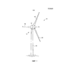
Фиг. 1 схематично ветровая турбина на виде в перспективе.FIG. 1 schematically shows a wind turbine in perspective view.
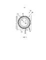
Фиг. 2 осевой вид в сечении известного синхронного генератора.FIG. 2 is an axial sectional view of a known synchronous generator.
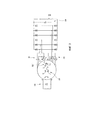
Фиг. 3 схематично принципиальная схема известного синхронного генератора с независимым возбуждением, содержащего две трехфазных обмотки и нижерасположенный диодный выпрямитель.FIG. 3 is a schematic diagram of a well-known independent excitation synchronous generator comprising two three-phase windings and a downstream diode rectifier.
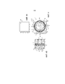
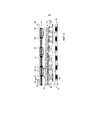
Фиг. 4 синхронный генератор согласно изобретению в осевом виде в сечении.FIG. 4, a synchronous generator according to the invention in axial sectional view.
Фиг. 4A и 4B фрагменты фиг. 4.FIG. 4A and 4B are fragments of FIG. four.
Фиг. 5A-5D различные возможные реализации переходной области в качестве вариантов осуществления относительно фрагмента, показанного на фиг. 4A.FIG. 5A-5D, various possible transition region implementations as embodiments with respect to the fragment shown in FIG. 4A.
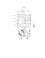
Фиг. 6 схематично один вариант для схемы сегментов синхронного генератора с нижерасположенным выпрямителем.FIG. 6 schematically, one embodiment for a circuit of segments of a synchronous generator with a downstream rectifier.
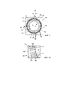
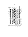
Фиг. 7 (A-C) синхронный генератор в осевом виде в сечении в соответствии с дополнительным вариантом осуществления, содержащий сегменты статора с различным количеством полюсных пар.FIG. 7 (A-C), an axial cross-sectional synchronous generator according to a further embodiment, comprising stator segments with a different number of pole pairs.
Фиг. 7A фрагмент фиг. 7.FIG. 7A is a fragment of FIG. 7.
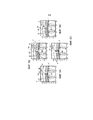
Фиг. 8 схема обмотки синхронного генератора одного варианта осуществления.FIG. 8 is a winding diagram of a synchronous generator of one embodiment.
Фиг. 9 схема обмотки синхронного генератора дополнительного варианта осуществления.FIG. 9 is a diagram of a winding of a synchronous generator of an additional embodiment.
Фиг. 1 показывает ветровую турбину 100, содержащую башню 102 и гондолу 104. Ротор 106 с тремя лопастями 108 ротора и обтекателем 110 размещается на гондоле 104. Ротор 106 переключается на вращательное движение в ходе работы посредством ветра и за счет этого приводит в действие генератор в гондоле 104.FIG. 1 shows a
Фиг. 2 показывает известный синхронный генератор 201 в осевом виде в сечении, т.е. в виде в направлении оси 202 вращения, при этом синхронный генератор 201 секционирован поперечно оси 202 вращения. Синхронный генератор имеет форму синхронного генератора с внутренним ротором и в силу этого имеет ротор или якорь 204 внутри и статор 206 снаружи. Синхронный генератор 201 имеет форму многополюсного кольцевого генератора и имеет свободную внутреннюю часть, которая занимает более половины полного диаметра или полного радиуса синхронного генератора 201. 168 зубьев 208 статора предоставляются в качестве примера. Предоставляется идентичное число пазов 210 статора, причем эти пазы статора сменяются зубьями 208 статора или размещаются между ними.FIG. 2 shows a known
Якорь 204 имеет некоторые полюсы 212 ротора или полюсные башмаки 212, между которыми в каждом случае предоставляются пазы 214 с обмотками. Пазы 214 ротора содержат обмотки для возбуждения ротора.
В ходе работы, ротор 204 вращается относительно статора 206, и полюсы 212 ротора быстро проходят мимо полюсов 208 статора. Узкий воздушный зазор 216 предоставляется между ротором 204 и статором 206.During operation, the
Фиг. 3 иллюстрирует разводку известного синхронного генератора 201 и схематично показывает схему 220 возбуждения для возбуждения ротора 204 посредством постоянного тока. Схематично показаны, соответственно, первая и вторая трехфазная обмотка 221 и 222 статора. Упомянутые обмотки статора соединяются через первое межкомпонентное соединение 223 или второе межкомпонентное соединение 224 через первый или второй выпрямитель 225 и 226, соответственно, и два выпрямителя 225 и 226 питают общее промежуточный контур 228 постоянного тока, которое символизируется посредством конденсатора.FIG. 3 illustrates the wiring of a known
Фиг. 4 теперь показывает, практически аналогично фиг. 2, синхронный генератор 1, содержащий ось 2 вращения, якорь или ротор 4, статор 6 и множество зубьев 8 статора и идентичное число пазов 10 статора. Якорь или ротор 4 имеет полюсы ротора или полюсные башмаки 12 и пазы 14 ротора между ними. Воздушный зазор 16 расположен между статором 6 и якорем 4. Ротор или якорь 4 может быть идентичным ротору или якорю 204 на фиг. 2. Тем не менее, статор 6 отличается от статора 206 на фиг. 2 в соответствии с изобретением.FIG. 4 now shows, in much the same way as FIG. 2, a
В этом отношении, статор 6 разделен на четыре сегмента 31-34. В каждом случае, смежные сегменты чередуются или смещаются относительно друг друга. Таким образом, первый и третий сегменты 31, 33 чередуются или смещаются не относительно друг друга, а относительно второго и четвертого сегментов 32, 34, соответственно. Аналогично, второй и четвертый сегменты 32, 34 не чередуются или смещаются относительно друг друга. В силу этого имеется сжатая область 36 или расширенная область 38 между смежными сегментами, в зависимости от того, соответственно, смежные сегменты смещаются или чередуются в направлении друг друга либо в направлении друг от друга. Фиг. 4A в этом случае подробно показывает часть синхронного генератора 1, которая связана со сжатой областью 36. Варианты для реализации этой сжатой области 36 показаны на фиг. 5A-5D. Фиг. 4B подробно показывает часть синхронного генератора 1, которая включает в себя расширенную область 38.In this regard, the
В отношении расширенной области 38 из фиг. 4B можно видеть, что предоставляется расширенный зуб 8+ статора, тогда как оставшиеся зубья 8 статора имеют меньшую ширину относительно него, а именно, нормальную ширину, а также являются идентичными по ширине друг с другом.With respect to the expanded
Соответственно, фиг. 4A должен иметь суженный зуб 8- или другую реализацию сжатой области для сжатой области 36, в которой все пазы 10 статора имеют идентичный размер и форму, но это представляет собой только один вариант для реализации. Фиг. 4A является просто прототипом для вариантов реализации, которые конкретно проиллюстрированы на фиг. 5A-5D.Accordingly, FIG. 4A should have a narrowed tooth 8- or another implementation of the compressed area for the compressed
Увеличения на фиг. 4B и 5A-5D также показывают то, что для якоря или ротора 4, зубья 12 и пазы 14 являются нетронутыми посредством сегментации и чередования или сжатия статора 6.The magnifications in FIG. 4B and 5A-5D also show that for the armature or
Следовательно, фиг. 5A-5D показывают подробности в соответствии с подробностью или прототипом на фиг. 4A и в этом случае показывают различные варианты для конкретной конфигурации сжатой области 36, которые обозначены, соответственно, как 36A, 36B, 36C и 36D на этих чертежах 5A-5D, соответственно. В этой сжатой области, два сегмента 31 и 32 статора, например, вращаются в направлении друг друга относительно традиционной компоновки, которая показана на фиг 2. Это приблизительно достигается посредством показателя ширины паза, причем в конфигурации, показанной на фиг. 4, и в силу этого также так, как показано на фиг. 5A-5D, ширина паза приблизительно соответствует ширине перемычки 40 каждого зуба 8.Therefore, FIG. 5A-5D show details in accordance with the detail or prototype of FIG. 4A, and in this case, show various options for the specific configuration of the compressed
Предпочтительно, это вращение двух смежных областей в направлении друг друга соответствует приблизительно половине среднего расстояния между зубьями или расстояния между пазами, т.е. половине расстояния от центра зуба до центра следующего зуба или от центра паза до центра следующего смежного паза.Preferably, this rotation of two adjacent regions in the direction of each other corresponds to approximately half the average distance between the teeth or the distance between the grooves, i.e. half the distance from the center of the tooth to the center of the next tooth or from the center of the groove to the center of the next adjacent groove.
Чтобы реализовывать сжатую область 36A, вариант осуществления, показанный на фиг. 5A, предлагает конфигурировать пазы 10A' и 10A'' непосредственно рядом друг с другом, так что они являются более узкими, а также предоставлять разделительную перемычку 42A между ними. Эта разделительная перемычка 42A может отделять эти два паза 10A' и 10A'' друг от друга и за счет этого также отделять все вставленные линии обмотки статора друг от друга. В этом отношении, эта разделительная перемычка 42A также может иметь электроизоляционную функцию. Одна проблема в данном случае состоит в том, что пазы 10A' и 10A'' уменьшаются по размеру по сравнению с пазами 10 и в силу этого могут также принимать линии обмотки статора в меньшей или менее оптимальной степени.In order to realize the
В качестве альтернативы, в силу этого предложена конфигурация, как показано на фиг. 5B, в которой два ограничительных паза 10B' и 10B'' предоставляются в сжатой области 36B, причем эти ограничительные пазы имеют большую глубину по сравнению с оставшимися пазами 10. Ограничительные пазы 10B' и 10B'' в силу этого являются более тонкими, но более глубокими, и за счет этого могут принимать приблизительно идентичное число линий или сердечников линий с другими пазами 10. Два ограничительных паза 10B' и 10B'' отделены посредством разделительной перемычки 42B, которая в любом случае может содержать материал, идентичный материалу оставшихся зубьев 8 и пакета пластин статора 6.Alternatively, therefore, a configuration is proposed as shown in FIG. 5B, in which two
Фиг. 5C показывает конфигурацию, почти идентичную конфигурации, показанной на фиг. 5B, но предоставляется разделительная перемычка 42C, которая изготовлена из материала, отличного от материала пакета пластин статора, т.е. из оставшихся зубьев 8 статора. Материал разделительной перемычки 42C изготовлен из высокопроницаемого материала, по меньшей мере, из материала, который имеет более высокую степень проницаемости по сравнению с пластиной статора. Для этого может использоваться, например, так называемый металл Mu. Вследствие этого высокопроницаемого материала уменьшенное поперечное сечение этой разделительной перемычки 42C может полностью или частично компенсироваться. В отличие от варианта осуществления, показанного на фиг. 5B, разделительная перемычка 42C также не перфорируется из соответствующей пластины, но может вставляться, как только пакет пластин статора 6 завершен, возможно также вместе со вставкой линий обмотки статора.FIG. 5C shows a configuration almost identical to that shown in FIG. 5B, but a
На фиг 5D показана дополнительная конфигурация, в которой два ограничительных паза 10D' и 10D''' теперь являются непосредственно смежными друг с другом без зуба статора между ними. Для разделения, например, может предоставляться разделительная перемычка 42D в качестве изоляционной бумаги, либо можно обходиться вообще без нее. Ограничительные пазы 10D' и 10D''' в этом случае имеют форму, идентичную форме оставшихся пазов 10, и, соответственно, имеют идентичный объем пространства или идентичный размер пространства для приема линий обмотки статора. Когда такие линии обмотки статора вставляются, необходимо обращать внимание на обеспечение того, что они в итоге укладываются максимально возможно равномерно в этих двух ограничительных пазах 10D', 10D''', которые являются смежными друг с другом без промежуточного зуба.FIG. 5D shows an additional configuration in which two
Фиг. 6 схематично иллюстрирует разводку обмоток статора синхронного генератора согласно изобретению в соответствии с одним вариантом осуществления. В этом случае, синхронный генератор с разделенным статором, как показано на фиг. 4, используется в качестве основы. Следовательно, предоставляются четыре сегмента 31-34 статора, при этом первый и третий сегменты 31 и 33 не смещаются или чередуются относительно друг друга, а чередуются относительно второго и четвертого сегментов 32 и 34. Второй и четвертый сегменты 32, 34 аналогично не чередуются или смещаются относительно друг друга. Следовательно, первый и третий сегменты 31, 33 схематично иллюстрируются в качестве первой области 44 или в качестве первой группы 44 сегментов, и, соответственно, второй и четвертый сегменты 32, 34 схематично иллюстрируются в качестве второй области 46 или второй группы 46 сегментов.FIG. 6 schematically illustrates the wiring of the stator windings of a synchronous generator according to the invention in accordance with one embodiment. In this case, a shared stator synchronous generator, as shown in FIG. 4, is used as a base. Therefore, four stator segments 31-34 are provided, with the first and
Две группы 44 и 46 сегментов имеют две трехфазные обмотки 51 и 53 и 52 и 54 статора, соответственно. В этом случае, в каждом случае, обе обмотки 51 и 53 и 52 и 54 статора проходят в каждом случае через оба сегмента 31 и 33 и 32 и 34, соответственно, рассматриваемой группы 44 и 46 сегментов. Ветви обмотки в каждом случае для одной обмотки 51-54 статора соединены электрически последовательно в группе 44 или 46 сегментов, а именно, из нейтральной точки 45 или 47 (указывается просто) через первый сегмент 51 или 52 статора, дополнительно через второй сегмент 53 или 54 статора и в завершение с одним из выпрямителей 61-64. Следовательно, две из обмоток 51-54 статора проходят через каждый сегмент.Two groups of 44 and 46 segments have two three-
В показанном варианте осуществления, в этом случае, каждая из четырех обмоток 51-54 статора соединена по отдельности с первым-четвертым выпрямителем 61-64. Все четыре выпрямителя 61-64 в этом случае используют один и тот же промежуточный контур 66 постоянного тока, в который все они в силу этого совместно подают питание. Промежуточный контур постоянного тока также символизируется посредством конденсатора 68, и нагрузочное сопротивление 70 символически выражает дополнительные элементы, которые должны быть соединены, а именно, в частности, один или более повышающих преобразователей, которые должны быть соединены, и/или один или более инверторов, которые должны быть соединены для формирования синусоидального переменного тока для подачи в питающую электросеть.In the embodiment shown, in this case, each of the four stator windings 51-54 is connected separately to the first to fourth rectifier 61-64. All four rectifiers 61-64 in this case use the same
Показанные выпрямители 61-64 сконфигурированы в качестве пассивных, так называемых B-6-выпрямителей.The rectifiers 61-64 shown are configured as passive, so-called B-6 rectifiers.
Вследствие того факта, что обмотки как первой области 44, так и второй области 46 соединены отдельно в каждом случае с выпрямителем или с набором выпрямителей, токи, сгенерированные по-разному в отношении любых гармоник вследствие чередования или смещения, также могут проходить, соответственно, отдельно в соответствующий выпрямитель и в силу этого отдельно в промежуточный контур 66 постоянного тока и подаются в него посредством выпрямителей. Сгенерированные переменные токи выпрямляются посредством выпрямления, но любые гармоники или накладываемая пульсация остаются присутствующими в значительной степени и затем могут присутствовать в промежуточном контуре постоянного тока, возможно в ослабленной форме в качестве пульсации напряжения или флуктуаций напряжения. В этом случае, пульсация, которая должна быть назначена для первой области 44, сдвигается относительно пульсации, которая должна быть назначена для второй области 46, и в процессе они накладываются в промежуточном контуре постоянного тока, и в силу этого могут ослаблять друг друга. В оптимальном, по меньшей мере, теоретическом случае, пульсация первой области 44 может компенсироваться посредством пульсации второй области 46.Due to the fact that the windings of both the
Помимо этого, в силу дополнительно отдельного межкомпонентного соединения отдельных сегментов 31-34 может увеличиваться степень резервирования генератора, а именно, в частности, статора.In addition, due to the additionally separate interconnect connection of the individual segments 31-34, the degree of redundancy of the generator, in particular, the stator, can increase.
Следовательно, предложен многополюсный синхронный кольцевой генератор ветровой турбины, который может работать с уменьшенными уровнями шума, в частности, по сравнению с ранее известными синхронными генераторами с идентичной в остальных отношениях конструкцией.Therefore, a multi-pole synchronous ring generator of a wind turbine is proposed, which can operate with reduced noise levels, in particular, in comparison with previously known synchronous generators with a design identical in other respects.
В частности, генератор, содержащий шесть фаз, а именно, первую и вторую систему в каждом случае с тремя фазами и статор с 12 пазами в расчете на шаг полюсов и диодный выпрямитель, также используется в качестве основы. Такой многополюсный синхронный кольцевой генератор в соответствии с предшествующим уровнем техники, в числе прочего, может генерировать пульсирующие крутящие моменты с содержаниями гармоник двенадцатого порядка. Такие пульсирующие крутящие моменты могут допускать, например, частоту приблизительно в 120 Гц, которая, естественно, зависит от частоты вращения и может быть раздражающей.In particular, a generator containing six phases, namely, the first and second system in each case with three phases and a stator with 12 grooves per pole pitch and a diode rectifier, is also used as the basis. In accordance with the prior art, such a multi-pole synchronous ring generator can, among other things, generate pulsating torques with twelfth-order harmonics. Such pulsating torques can tolerate, for example, a frequency of approximately 120 Hz, which naturally depends on the rotational speed and can be annoying.
Следовательно, предложенное решение состоит в разделении обмотки статора, или обмоток статора на сегменты, в частности, на четыре сегмента. Пазы сегментов чередуются таким образом, что сдвиг в половину шага по пазам формируется между сегментами, как показано на фиг. 4 с помощью увеличений 4A и 4B. В результате получаются соответствующие краевые области обмотки, которые могут иметь форму сжатой области 36 или расширенной области 38, которые сменяются по окружности статора. Конфигурация этих краевых областей обмотки может быть такой, как показано на фиг. 5A-5D. Дополнительные возможные конфигурации аналогично не исключаются.Therefore, the proposed solution consists in dividing the stator winding, or stator windings into segments, in particular, into four segments. The grooves of the segments alternate in such a way that a half-pitch shift in the grooves is formed between the segments, as shown in FIG. 4 using magnifications 4A and 4B. The result is the corresponding edge region of the winding, which may be in the form of a
Помимо этого, предлагается соединять в каждом случае два несмежных сегмента, а именно, формировать одну область. Типично, это межкомпонентное соединение может осуществляться посредством последовательной схемы. Межкомпонентное соединение в этом случае связано с фазами трехфазной обмотки в каждом случае. Следовательно, каждая соединенная область в каждом случае состоит из двух фаз трехфазной обмотки. Предпочтительно, каждая область соединяется со схемой 12-импульсного диодного выпрямления и с параллельной схемой на стороне постоянного напряжения.In addition, it is proposed to connect in each case two non-adjacent segments, namely, to form one area. Typically, this interconnect may be implemented through a series circuit. Interconnect in this case is associated with the phases of the three-phase winding in each case. Therefore, each connected region in each case consists of two phases of a three-phase winding. Preferably, each region is connected to a 12-pulse diode rectification circuit and to a parallel circuit on the constant voltage side.
Предложенное решение подробно пояснено с использованием примера подразделения статора на четыре сегмента. Тем не менее, другие подразделения также могут выполняться, в простейшем случае подразделение на два сегмента, причем в этом случае каждый отдельный сегмент также формирует область в смысле первой или второй области 44, 46. Аналогично, может выполняться подразделение на значительно большее число, чем четыре сегмента, например, на четное число сегментов.The proposed solution is explained in detail using an example of dividing the stator into four segments. However, other units can also be performed, in the simplest case, a division into two segments, in which case each separate segment also forms a region in the sense of the first or
Фиг. 7 показывает в виде в сечении синхронный генератор 701, содержащий статор 706 с четырьмя сегментами статора или сегментами 731-734. Сегменты 731 и 733 статора формируют первую группу сегментов, а сегменты 732 и 734 статора формируют вторую группу сегментов. Каждая из этих групп 731, 733 и 732, 734 сегментов имеет 42 полюсных пары и в силу этого число полюсных пар, которое не является кратным числом четырех. Соответственно, сегменты статора из группы сегментов имеют различные числа полюсных пар, а именно, первый сегмент 731 статора имеет 24 полюсных пары, а второй сегмент 733 статора имеет 18 полюсных пар. Соответственно, из второй группы сегментов, сегмент 732 статора имеет 24 полюсных пары и, из этой же группы сегментов, сегмент 734 статора имеет 18 полюсных пар. Следовательно, каждый из этих четырех сегментов 731-734 статора также имеет, в качестве числа полюсных пар, кратное число шести, или другими словами число полюсных пар каждого из сегментов 731-734 статора может делиться на число шесть без остатка.FIG. 7 shows a cross-sectional view of a
Кроме того, пазы статора идентифицируются посредством ссылки с номером 710, и зубья статора идентифицируются посредством ссылки с номером 708 на фиг. 7. Ротор 4 может соответствовать ротору 4 на фиг. 4, и в этом отношении также следует обратиться к пояснению в отношении фиг. 4 на предмет дополнительного описания упомянутого ротора.Furthermore, stator slots are identified by
Разделение между отдельными сегментами 731-734 статора указывается посредством соответствующих черт 735. По сравнению с вариантом осуществления, показанным на фиг. 4, в силу этого имеется сдвиг расширенной области 738, которая аналогично имеет расширенный зуб 708+ статора. Эта расширенная область 738 с расширенным зубом 708+ размещается в подробности B на фиг. 7, которая проиллюстрирована в увеличенной форме на фиг. 7A. Помимо сдвига этой расширенной области 738 или расширенного зуба 708+, остальная часть описания в этом отношении применяется к варианту осуществления, показанному на фиг. 4, и увеличенная иллюстрация на фиг. 4B, соответственно, также служит для варианта осуществления на фиг. 7 или 7A.Separation between the individual stator segments 731-734 is indicated by corresponding
Сжатая область 736 в принципе является неизменной и также расположена в метке A на фиг. 7. Для этой метки A, также возможны различные разновидности, которые описываются на фиг. 5A-5D. В этом отношении, следует обратиться к данным чертежам 5A-5D.The
Фиг. 8 иллюстрирует схему обмотки для синхронного генератора в соответствии с одним вариантом осуществления для сегмента статора, такого как, например, сегмент 733 статора на фиг. 7 с 18 полюсными парами. Этот сегмент статора, которому присвоена ссылка с номером 833 на фиг. 8, проиллюстрирован в качестве расширенного элемента без искривления на фиг. 8, чтобы за счет этого упрощать иллюстрацию схемы обмотки. Фиг. 8 в этом случае показывает вид сверху соответствующих зубьев 808 и пазов 810 в виде 8A, вид сбоку сегмента статора 3 в виде 8B, вид сбоку аналогично линейно проиллюстрированной части ротора 804 в виде 8C, причем иллюстрация в этом случае также является схематической и без искривления, и вид сверху зубьев ротора или полюсных башмаков ротора 804 в иллюстрации 8D.FIG. 8 illustrates a winding diagram for a synchronous generator in accordance with one embodiment for a stator segment, such as, for example, the
Вид 8A на фиг. 8 иллюстрирует схему обмотки, в принципе начинающуюся слева с ветви 850 обмотки, которая укладывается через первый паз 851, т.е. в принципе в прямом направлении и проходит назад через второй паз 852. Эта ветвь 850 обмотки затем проходит в первый паз 851 и проходит через него еще раз и проходит назад снова через второй паз 852. Это повторяется еще два раза, так что ветвь 850 обмотки затем укладывается приблизительно вокруг шести зубьев 808 в трех полных контурах 858. Тем не менее, как результат, четыре витка являются электромагнитно эффективными, поскольку ветвь обмотки, входящая в начале, т.е. слева, как показано на фиг. 8, вид 8A, электрически эффективно соединяется в завершение с этой частью ветви 850 обмотки, которая оставляет второй паз 852 вправо в завершение, как только, по меньшей мере, показанный сегмент 833 статора полностью намотан.
После того, как ветвь 850 обмотки проходит назад через второй паз 852 в четвертый раз, она теперь вставляется в третий паз 853 и проходит назад через четвертый паз 854, и это повторяется до тех пор, пока не будут сформированы снова три контура или четыре электромагнитно эффективных витка. Тем не менее, это повторяется в пятом и шестом пазу 855 и 856, соответственно, до тех пор, пока ветвь 850 обмотки не перейдет в правую часть на фиг. 8, вид 8A. Исходя из этого, ветвь 850 обмотки может проходить в дополнительный сегмент статора или соединяться с выводом, чтобы предоставлять ток, который должен генерироваться в нем.After the
Вид 8B схематично показывает все зубья 808 и пазы 810 сегмента 833 статора. В качестве иллюстрации, пазы 810 идентифицируются посредством A-F, при этом в каждом случае одна буква означает одну ветвь обмотки одной фазы. Обмотка, проиллюстрированная в виде 8A в этом случае, связана с фазой обмотки для фазы, которая идентифицируется посредством буквы D. В этом случае, D+ в каждом случае обозначает ветвь 850 обмотки, проходящую вперед, а D- в каждом случае идентифицирует ветвь 850 обмотки, проходящую назад. Оставшиеся буквы A-C и E и F предоставляются с соответствующими символами, т.е. "+" для "вперед" и "-" для "назад".
Вид 8B на фиг. 8 также показывает то, что ветвь обмотки предоставляется в каждом случае в четырех слоях в каждом пазу 810 статора. Кроме того, вид 8B также указывает то, что в каждом случае соответствующая обмотка предоставляется для других фаз A в C, E и F, как проиллюстрировано посредством вида только для одной фазы, а именно, фазы D.
Вид 8C подробно показывает, для ротора 804, часть с шестью полюсными башмаками 860, которые имеют смысл чередования направления, чтобы генерировать в каждом случае магнитное поле с обратным направлением относительно соответствующего смежного полюсного башмака в случае возбуждения посредством постоянного тока в фазах 862 обмотки возбуждения. Каждый полюсный башмак 860 имеет головку 864 полюсного башмака, который имеет приблизительно форму стрелки, как видно из вида 8D. Направление перемещения ротора 804 является корректным в направлении стрелки 866 перемещения. Два полюсных башмака 860 и в силу этого два полюса ротора, т.е. полюсная пара ротора, охватывают всего 12 зубьев 808 статора или 12 пазов 810 статора и в силу этого шесть полюсных пар статора.View 8C shows in detail, for the
Фиг. 9 показывает или иллюстрирует схему обмотки для двенадцатиполюсного двенадцатифазового синхронного генератора в иллюстрации, почти идентичной иллюстрации, показанной на фиг. 8. Основной синхронный генератор имеет четыре сегмента 931-934. Первый и третий сегменты 931 и 933 формируют первую группу сегментов, а второй и четвертый сегменты 932 и 934 формируют вторую группу сегментов. Каждая из этих двух групп сегментов имеет две трехфазных обмотки, т.е. в каждом случае шесть обмоток. Тем не менее, в качестве иллюстрации, в каждом случае проиллюстрирована только одна обмотка или только одна фаза 950 или 980 обмотки. Фиг. 9 аналогично показывает четыре вида в смысле видов 8A-8D, а именно, соответственно, в качестве видов 9A-9D. Тем не менее, только иллюстрация 9A показывает непрерывную ветвь950 или 980 обмотки.FIG. 9 shows or illustrates a winding circuit for a twelve-pole twelve-phase synchronous generator in an illustration almost identical to that shown in FIG. 8. The main synchronous generator has four segments 931-934. The first and
Для первой группы сегментов, состоящей из первого и третьего сегментов 931 и 933, ветвь 950 обмотки начинается в общей нейтральной точке 995. ветвь 950 обмотки является частью трехфазной обмотки с двумя дополнительными фазами обмотки (не проиллюстрировано на фиг. 9). Следовательно, эти три ветви обмотки формируют трехфазную систему и соединяются относительно друг друга в нейтральной точке 995. Из этой нейтральной точки 995, ветвь950 обмотки сначала проходит через первый паз 951 и проходит обратно через второй паз 952 и укладывается через два паза 951, 952 в трех контурах 958 и в силу этого в четырех электромагнитно эффективных витках. Затем эта ветвь950 обмотки проходит в первый сегмент 931 и укладывается в нем через третий паз 953 и проходит назад через четвертый паз 954 до тех пор, пока не будут сформированы три контура. Ветвь обмотки затем продолжается в пятом пазу 955 и проходит назад через шестой паз 956 множество раз, с тем чтобы формировать три контура. В завершение, иллюстрация для ветви 950 обмотки завершается в точке 996 соединения. Из этой точки соединения, фаза 950 обмотки или другая соединенная электрическая линия проходит в выпрямитель, к примеру, в B-6-выпрямитель 61, показанный на фиг. 6, а именно, в ветвь с двумя диодами.For the first group of segments, consisting of the first and
Аналогичным образом, оставшиеся пазы содержат оставшиеся пять ветвей обмотки этих двух трехфазных систем, так что в итоге все пазы этой первой группы сегментов первого и второго сегментов 931 и 933 затем заполняются.Similarly, the remaining grooves contain the remaining five branches of the winding of these two three-phase systems, so that in the end all the grooves of this first group of segments of the first and
Соответственно, выполняется обмотка второго и четвертого сегментов 932 и 934 второй группы сегментов с ветвью 980 обмотки. Упомянутая ветвь 980 обмотки наматывается из общей нейтральной точки 998 через первый-шестой паз 981-986 с соответствующими контурами 988 и завершается в точке 999 соединения для соединения с выпрямителем.Accordingly, the winding of the second and
Синхронный генератор, показанный на фиг. 9, имеет первую и вторую группу сегментов, имеющих 18 полюсных пар. Следовательно, предоставляются четыре сегмента 931-934 статора, которые сгруппированы в две группы 931 и 933 и 932 и 934 сегментов. Каждая группа сегментов в силу этого не имеет числа полюсных пар, которое является кратным числом четырех, и за счет этого сегменты статора из группы сегментов имеют различные числа полюсных пар, а именно, соответственно, больший сегмент 931 или 932 статора имеет двенадцать полюсных пар, и, соответственно, меньший сегмент 933 или 934 статора имеет шесть полюсных пар. Следует упомянуть, что предоставленное чередование не показано на фиг. 9 по причинам упрощенной иллюстрации схемы обмотки. Фиг. 9 служит для того, чтобы прояснять схему обмотки.The synchronous generator shown in FIG. 9, has a first and second group of segments having 18 pole pairs. Consequently, four stator segments 931-934 are provided, which are grouped into two groups of 931 and 933 and 932 and 934 segments. Each group of segments by virtue of this does not have a number of pole pairs, which is a multiple of four, and due to this, the stator segments from the group of segments have different numbers of pole pairs, namely, accordingly, the
Claims (71)
Applications Claiming Priority (3)
| Application Number | Priority Date | Filing Date | Title |
|---|---|---|---|
| DE102014200947.2A DE102014200947A1 (en) | 2014-01-20 | 2014-01-20 | Synchronous generator of a gearless wind turbine |
| DE102014200947.2 | 2014-01-20 | ||
| PCT/EP2014/077392 WO2015106891A2 (en) | 2014-01-20 | 2014-12-11 | Synchronous generator in a gearless wind turbine |
Publications (1)
| Publication Number | Publication Date |
|---|---|
| RU2643778C1 true RU2643778C1 (en) | 2018-02-06 |
Family
ID=52232145
Family Applications (1)
| Application Number | Title | Priority Date | Filing Date |
|---|---|---|---|
| RU2016133756A RU2643778C1 (en) | 2014-01-20 | 2014-12-11 | Synchronous generator in direct-drive wind turbine |
Country Status (17)
| Country | Link |
|---|---|
| US (1) | US20160336834A1 (en) |
| EP (1) | EP3097627A2 (en) |
| JP (1) | JP6291597B2 (en) |
| KR (1) | KR101879112B1 (en) |
| CN (1) | CN106415996B (en) |
| AR (1) | AR099131A1 (en) |
| AU (1) | AU2014377432B2 (en) |
| BR (1) | BR112016016564A2 (en) |
| CA (1) | CA2936261A1 (en) |
| CL (1) | CL2016001816A1 (en) |
| DE (1) | DE102014200947A1 (en) |
| MX (1) | MX358154B (en) |
| RU (1) | RU2643778C1 (en) |
| SG (1) | SG11201605830QA (en) |
| TW (1) | TWI555309B (en) |
| WO (1) | WO2015106891A2 (en) |
| ZA (1) | ZA201604562B (en) |
Families Citing this family (10)
| Publication number | Priority date | Publication date | Assignee | Title |
|---|---|---|---|---|
| DE102016108712A1 (en) | 2016-05-11 | 2017-11-16 | Wobben Properties Gmbh | Synchronous generator of a gearless wind turbine and method for producing a synchronous generator and use of form coils |
| US11336134B2 (en) * | 2016-10-04 | 2022-05-17 | Holcomb Scientific Research Limited | Solid state multi-pole and uni-pole electric generator rotor for AC/DC electric generators |
| US11196314B2 (en) | 2017-02-02 | 2021-12-07 | Siemens Gamesa Renewable Energy A/S | Segmented stator electrical machine |
| DE102017112958A1 (en) | 2017-06-13 | 2018-12-13 | Wobben Properties Gmbh | Wind turbine with gearless generator and generator filter |
| FR3069113A1 (en) * | 2017-07-11 | 2019-01-18 | Valeo Equipements Electriques Moteur | METHOD FOR CONTROLLING A POLYPHASE ROTARY ELECTRIC MACHINE AND ROTATING ELECTRIC MACHINE USING THE SAME |
| DE102017119530A1 (en) * | 2017-08-25 | 2019-02-28 | Wobben Properties Gmbh | Generator rotor and generator stator and generator and wind turbine and method for transporting a generator |
| US10608565B2 (en) * | 2017-12-07 | 2020-03-31 | General Electric Company | Systems and methods for rotating a crankshaft to start an engine |
| DE102018115114A1 (en) * | 2018-06-22 | 2019-12-24 | Wobben Properties Gmbh | Method for controlling a generator of a wind turbine |
| CN111193431A (en) * | 2020-02-05 | 2020-05-22 | 北京纳米能源与系统研究所 | Direct current output friction nanometer power generation device and sensing equipment |
| EP4012897A1 (en) | 2020-12-14 | 2022-06-15 | Flender GmbH | Method for fixing stator segments of a segmented dynamoelectric machine |
Citations (6)
| Publication number | Priority date | Publication date | Assignee | Title |
|---|---|---|---|---|
| SU861715A1 (en) * | 1979-05-07 | 1981-09-07 | Московский Ордена Ленина Энергетический Институт | Reduction gear free wind unit |
| JP2000287420A (en) * | 1999-01-28 | 2000-10-13 | Mitsubishi Electric Corp | Alternator |
| WO2003073583A1 (en) * | 2002-02-28 | 2003-09-04 | Abb Research Ltd. | Synchronous generator |
| US20110266811A1 (en) * | 2010-04-30 | 2011-11-03 | Alstom Hydro France | Synchronous generator, especially for wind turbines |
| US20120074797A1 (en) * | 2010-09-23 | 2012-03-29 | Northern Power Systems, Inc. | Sectionalized Electromechanical Machines Having Low Torque Ripple and Low Cogging Torque Characteristics |
| WO2013174566A2 (en) * | 2012-05-22 | 2013-11-28 | Wobben Properties Gmbh | Synchronous generator of a gearless wind energy turbine |
Family Cites Families (32)
| Publication number | Priority date | Publication date | Assignee | Title |
|---|---|---|---|---|
| CH486154A (en) * | 1965-12-06 | 1970-02-15 | Circuit Res Company | Dynamo-electric machine with a wire-wound, disc-shaped rotor |
| US4315171A (en) * | 1977-05-23 | 1982-02-09 | Ernest Schaeffer | Step motors |
| US5173651A (en) * | 1985-06-28 | 1992-12-22 | Kollmorgen Technologies Corporation | Electrical drive systems |
| US4990809A (en) * | 1987-04-27 | 1991-02-05 | The Superior Electric Company | Variable reluctance motor |
| US6321439B1 (en) * | 1997-01-21 | 2001-11-27 | Siemens Westinghouse Power Corporation | Method for assembly of a stator in the field |
| DE19729034A1 (en) * | 1997-07-08 | 1999-01-21 | Aloys Wobben | Synchronous generator for use in wind turbines and wind turbines |
| JP3428896B2 (en) * | 1998-05-07 | 2003-07-22 | オークマ株式会社 | Motor with reduced torque ripple |
| TW483216B (en) * | 1998-09-08 | 2002-04-11 | Toshiba Corp | Motor |
| DE19923925A1 (en) * | 1999-05-26 | 2000-12-07 | Aloys Wobben | Synchronous machine |
| TW595067B (en) * | 2000-04-19 | 2004-06-21 | Wellington Drive Technologies | Method of producing stator windings |
| DE10110466A1 (en) * | 2001-03-05 | 2002-09-26 | Compact Dynamics Gmbh | Assembly of an electrical machine and electrical machine with such an assembly |
| EP1416608A1 (en) * | 2001-08-09 | 2004-05-06 | Honda Giken Kogyo Kabushiki Kaisha | Stator and method for manufacturing stator |
| KR100727372B1 (en) * | 2001-09-12 | 2007-06-12 | 토소가부시키가이샤 | Ruthenium complex, manufacturing process thereof and the method for forming thin-film using the complex |
| JP4093814B2 (en) * | 2002-07-30 | 2008-06-04 | 東洋電機製造株式会社 | Small wind power generator |
| DE10340114A1 (en) * | 2002-09-06 | 2004-03-18 | Luk Lamellen Und Kupplungsbau Beteiligungs Kg | Rotating electrical machine with soft magnetic laminations packet formed from electrically-conductive sheet metal band with stamped out sections between winding slots |
| DE10342755B4 (en) * | 2002-09-17 | 2018-06-14 | Denso Corporation | Rotating high voltage electric machine |
| JP2004194497A (en) * | 2002-11-29 | 2004-07-08 | Denso Corp | Combined stator core of rotary electric machine |
| JP4712465B2 (en) * | 2005-07-20 | 2011-06-29 | ヤマハ発動機株式会社 | Rotating electric machine and electric wheelchair |
| DE102005061892A1 (en) * | 2005-12-23 | 2007-06-28 | Robert Bosch Gmbh | Electrical machine for use as three-phase alternator in motor vehicle, has stator winding with seven phase strands that are interconnected in series, where electrically successive phase strand jumps-over in series-connection of strands |
| DE102007003618A1 (en) * | 2007-01-18 | 2008-07-24 | Voith Patent Gmbh | Power generation plant driven by a wind or water flow |
| JP4885073B2 (en) * | 2007-06-20 | 2012-02-29 | 三菱重工業株式会社 | Wind turbine rotor blade suspension device, wind turbine rotor blade attachment method, and wind turbine generator construction method |
| DE102009015044A1 (en) * | 2008-05-02 | 2009-11-05 | Hartmuth Drews | Segment wreath ring generator |
| TWI463068B (en) * | 2008-11-17 | 2014-12-01 | Jiann Fuh Chen | Synchronous generator for direct driving wind power/tide |
| FR2941105B1 (en) * | 2009-01-15 | 2016-01-01 | Valeo Equip Electr Moteur | ROTATING ELECTRIC MACHINE, ESPECIALLY FOR A MOTOR VEHICLE STARTER |
| EP2224578A1 (en) * | 2009-02-27 | 2010-09-01 | ABB Research Ltd. | Stator winding scheme of a permanent magnet machine |
| EP2416471B1 (en) * | 2009-12-18 | 2020-02-12 | Toyota Jidosha Kabushiki Kaisha | Stator |
| CN102884714B (en) * | 2010-04-13 | 2016-09-28 | Abb研究有限公司 | There is the crooked rotor magnetic pole of circumference and the motor of stator coil |
| DE102010015441A1 (en) * | 2010-04-16 | 2011-10-20 | Fachhochschule Gelsenkirchen | Transverse flux machine and method for producing the same |
| EP2403111B1 (en) * | 2010-06-29 | 2017-05-17 | Siemens Aktiengesellschaft | Generator, wind turbine, method of assembling a generator and use of a generator in a wind turbine |
| US9281731B2 (en) * | 2010-09-23 | 2016-03-08 | Northem Power Systems, Inc. | Method for maintaining a machine having a rotor and a stator |
| WO2012097107A1 (en) * | 2011-01-11 | 2012-07-19 | Qm Power, Inc. | Magnetically isolated phase interior permanent magnet electrical rotating machine |
| DK2492501T3 (en) * | 2011-02-25 | 2017-07-03 | Siemens Ag | Windmill |
-
2014
- 2014-01-20 DE DE102014200947.2A patent/DE102014200947A1/en not_active Withdrawn
- 2014-12-11 RU RU2016133756A patent/RU2643778C1/en not_active IP Right Cessation
- 2014-12-11 CA CA2936261A patent/CA2936261A1/en not_active Abandoned
- 2014-12-11 WO PCT/EP2014/077392 patent/WO2015106891A2/en active Application Filing
- 2014-12-11 JP JP2016564386A patent/JP6291597B2/en not_active Expired - Fee Related
- 2014-12-11 SG SG11201605830QA patent/SG11201605830QA/en unknown
- 2014-12-11 EP EP14820778.0A patent/EP3097627A2/en not_active Withdrawn
- 2014-12-11 MX MX2016009202A patent/MX358154B/en active IP Right Grant
- 2014-12-11 US US15/112,658 patent/US20160336834A1/en not_active Abandoned
- 2014-12-11 AU AU2014377432A patent/AU2014377432B2/en not_active Ceased
- 2014-12-11 KR KR1020167022688A patent/KR101879112B1/en active IP Right Grant
- 2014-12-11 CN CN201480073705.4A patent/CN106415996B/en not_active Expired - Fee Related
- 2014-12-11 BR BR112016016564A patent/BR112016016564A2/en not_active Application Discontinuation
- 2014-12-29 TW TW103146130A patent/TWI555309B/en not_active IP Right Cessation
-
2015
- 2015-01-20 AR ARP150100143A patent/AR099131A1/en unknown
-
2016
- 2016-07-05 ZA ZA2016/04562A patent/ZA201604562B/en unknown
- 2016-07-15 CL CL2016001816A patent/CL2016001816A1/en unknown
Patent Citations (6)
| Publication number | Priority date | Publication date | Assignee | Title |
|---|---|---|---|---|
| SU861715A1 (en) * | 1979-05-07 | 1981-09-07 | Московский Ордена Ленина Энергетический Институт | Reduction gear free wind unit |
| JP2000287420A (en) * | 1999-01-28 | 2000-10-13 | Mitsubishi Electric Corp | Alternator |
| WO2003073583A1 (en) * | 2002-02-28 | 2003-09-04 | Abb Research Ltd. | Synchronous generator |
| US20110266811A1 (en) * | 2010-04-30 | 2011-11-03 | Alstom Hydro France | Synchronous generator, especially for wind turbines |
| US20120074797A1 (en) * | 2010-09-23 | 2012-03-29 | Northern Power Systems, Inc. | Sectionalized Electromechanical Machines Having Low Torque Ripple and Low Cogging Torque Characteristics |
| WO2013174566A2 (en) * | 2012-05-22 | 2013-11-28 | Wobben Properties Gmbh | Synchronous generator of a gearless wind energy turbine |
Also Published As
| Publication number | Publication date |
|---|---|
| CL2016001816A1 (en) | 2016-12-09 |
| AR099131A1 (en) | 2016-06-29 |
| SG11201605830QA (en) | 2016-09-29 |
| CN106415996B (en) | 2020-04-03 |
| KR20160111475A (en) | 2016-09-26 |
| DE102014200947A1 (en) | 2015-08-06 |
| CN106415996A (en) | 2017-02-15 |
| BR112016016564A2 (en) | 2017-08-08 |
| US20160336834A1 (en) | 2016-11-17 |
| MX358154B (en) | 2018-08-07 |
| MX2016009202A (en) | 2016-10-03 |
| JP6291597B2 (en) | 2018-03-14 |
| AU2014377432B2 (en) | 2018-01-25 |
| AU2014377432A1 (en) | 2016-07-28 |
| CA2936261A1 (en) | 2015-07-23 |
| WO2015106891A2 (en) | 2015-07-23 |
| ZA201604562B (en) | 2017-09-27 |
| KR101879112B1 (en) | 2018-07-16 |
| EP3097627A2 (en) | 2016-11-30 |
| WO2015106891A3 (en) | 2015-09-17 |
| TWI555309B (en) | 2016-10-21 |
| JP2017505103A (en) | 2017-02-09 |
| TW201541818A (en) | 2015-11-01 |
Similar Documents
| Publication | Publication Date | Title |
|---|---|---|
| RU2643778C1 (en) | Synchronous generator in direct-drive wind turbine | |
| CN109565190B (en) | Electric machine comprising a stator with a uniform slot distribution | |
| US11038391B2 (en) | Distributed cascaded winding for electric machines | |
| RU2402140C2 (en) | Electric machine, namely synchronous engine with standby stator windings | |
| US20160049838A1 (en) | Synchronous machine | |
| EP2006977A3 (en) | Alternator for vehicle and rotating electrical machine | |
| US9502936B2 (en) | Three-phase AC motor | |
| CN104956573A (en) | Electrical machines | |
| US10199896B2 (en) | Direct current machine | |
| CN207910572U (en) | Rotary magnetic field motor with the poles 2p stator | |
| EP2717433A1 (en) | Rotor structure and electrical machine | |
| EP2717432A1 (en) | Rotor structure and electrical machine | |
| JP5602889B2 (en) | Winding structure and rotating electric machine | |
| SU978273A2 (en) | Versions of combinated three-phase/one-phase winding of electric machines | |
| JP2005204420A (en) | Stator for dynamo-electric machine | |
| WO2015032624A1 (en) | Stator winding of a rotating electrical machine | |
| KR20130093269A (en) | Apparatus for multiphase generator |
Legal Events
| Date | Code | Title | Description |
|---|---|---|---|
| MM4A | The patent is invalid due to non-payment of fees |
Effective date: 20201212 |