RU2638822C2 - Lighting device based on light guide with light-scattering particles and light angle selection module - Google Patents
Lighting device based on light guide with light-scattering particles and light angle selection module Download PDFInfo
- Publication number
- RU2638822C2 RU2638822C2 RU2015111537A RU2015111537A RU2638822C2 RU 2638822 C2 RU2638822 C2 RU 2638822C2 RU 2015111537 A RU2015111537 A RU 2015111537A RU 2015111537 A RU2015111537 A RU 2015111537A RU 2638822 C2 RU2638822 C2 RU 2638822C2
- Authority
- RU
- Russia
- Prior art keywords
- light
- emitting element
- input
- lighting device
- incidence
- Prior art date
Links
Images
Classifications
-
- G—PHYSICS
- G02—OPTICS
- G02B—OPTICAL ELEMENTS, SYSTEMS OR APPARATUS
- G02B6/00—Light guides; Structural details of arrangements comprising light guides and other optical elements, e.g. couplings
- G02B6/0001—Light guides; Structural details of arrangements comprising light guides and other optical elements, e.g. couplings specially adapted for lighting devices or systems
- G02B6/0011—Light guides; Structural details of arrangements comprising light guides and other optical elements, e.g. couplings specially adapted for lighting devices or systems the light guides being planar or of plate-like form
- G02B6/0013—Means for improving the coupling-in of light from the light source into the light guide
- G02B6/0023—Means for improving the coupling-in of light from the light source into the light guide provided by one optical element, or plurality thereof, placed between the light guide and the light source, or around the light source
-
- G—PHYSICS
- G02—OPTICS
- G02B—OPTICAL ELEMENTS, SYSTEMS OR APPARATUS
- G02B6/00—Light guides; Structural details of arrangements comprising light guides and other optical elements, e.g. couplings
- G02B6/0001—Light guides; Structural details of arrangements comprising light guides and other optical elements, e.g. couplings specially adapted for lighting devices or systems
- G02B6/0011—Light guides; Structural details of arrangements comprising light guides and other optical elements, e.g. couplings specially adapted for lighting devices or systems the light guides being planar or of plate-like form
- G02B6/0033—Means for improving the coupling-out of light from the light guide
- G02B6/0035—Means for improving the coupling-out of light from the light guide provided on the surface of the light guide or in the bulk of it
- G02B6/004—Scattering dots or dot-like elements, e.g. microbeads, scattering particles, nanoparticles
- G02B6/0041—Scattering dots or dot-like elements, e.g. microbeads, scattering particles, nanoparticles provided in the bulk of the light guide
-
- G—PHYSICS
- G02—OPTICS
- G02B—OPTICAL ELEMENTS, SYSTEMS OR APPARATUS
- G02B6/00—Light guides; Structural details of arrangements comprising light guides and other optical elements, e.g. couplings
- G02B6/0001—Light guides; Structural details of arrangements comprising light guides and other optical elements, e.g. couplings specially adapted for lighting devices or systems
- G02B6/0011—Light guides; Structural details of arrangements comprising light guides and other optical elements, e.g. couplings specially adapted for lighting devices or systems the light guides being planar or of plate-like form
- G02B6/0013—Means for improving the coupling-in of light from the light source into the light guide
- G02B6/0023—Means for improving the coupling-in of light from the light source into the light guide provided by one optical element, or plurality thereof, placed between the light guide and the light source, or around the light source
- G02B6/0028—Light guide, e.g. taper
-
- G—PHYSICS
- G02—OPTICS
- G02B—OPTICAL ELEMENTS, SYSTEMS OR APPARATUS
- G02B6/00—Light guides; Structural details of arrangements comprising light guides and other optical elements, e.g. couplings
- G02B6/0001—Light guides; Structural details of arrangements comprising light guides and other optical elements, e.g. couplings specially adapted for lighting devices or systems
- G02B6/0011—Light guides; Structural details of arrangements comprising light guides and other optical elements, e.g. couplings specially adapted for lighting devices or systems the light guides being planar or of plate-like form
- G02B6/0013—Means for improving the coupling-in of light from the light source into the light guide
- G02B6/0023—Means for improving the coupling-in of light from the light source into the light guide provided by one optical element, or plurality thereof, placed between the light guide and the light source, or around the light source
- G02B6/003—Lens or lenticular sheet or layer
-
- G—PHYSICS
- G02—OPTICS
- G02B—OPTICAL ELEMENTS, SYSTEMS OR APPARATUS
- G02B6/00—Light guides; Structural details of arrangements comprising light guides and other optical elements, e.g. couplings
- G02B6/0001—Light guides; Structural details of arrangements comprising light guides and other optical elements, e.g. couplings specially adapted for lighting devices or systems
- G02B6/0011—Light guides; Structural details of arrangements comprising light guides and other optical elements, e.g. couplings specially adapted for lighting devices or systems the light guides being planar or of plate-like form
- G02B6/0013—Means for improving the coupling-in of light from the light source into the light guide
- G02B6/0023—Means for improving the coupling-in of light from the light source into the light guide provided by one optical element, or plurality thereof, placed between the light guide and the light source, or around the light source
- G02B6/0031—Reflecting element, sheet or layer
-
- G—PHYSICS
- G02—OPTICS
- G02B—OPTICAL ELEMENTS, SYSTEMS OR APPARATUS
- G02B6/00—Light guides; Structural details of arrangements comprising light guides and other optical elements, e.g. couplings
- G02B6/0001—Light guides; Structural details of arrangements comprising light guides and other optical elements, e.g. couplings specially adapted for lighting devices or systems
- G02B6/0011—Light guides; Structural details of arrangements comprising light guides and other optical elements, e.g. couplings specially adapted for lighting devices or systems the light guides being planar or of plate-like form
- G02B6/0033—Means for improving the coupling-out of light from the light guide
- G02B6/0035—Means for improving the coupling-out of light from the light guide provided on the surface of the light guide or in the bulk of it
- G02B6/0045—Means for improving the coupling-out of light from the light guide provided on the surface of the light guide or in the bulk of it by shaping at least a portion of the light guide
-
- G—PHYSICS
- G02—OPTICS
- G02B—OPTICAL ELEMENTS, SYSTEMS OR APPARATUS
- G02B6/00—Light guides; Structural details of arrangements comprising light guides and other optical elements, e.g. couplings
- G02B6/0001—Light guides; Structural details of arrangements comprising light guides and other optical elements, e.g. couplings specially adapted for lighting devices or systems
- G02B6/0011—Light guides; Structural details of arrangements comprising light guides and other optical elements, e.g. couplings specially adapted for lighting devices or systems the light guides being planar or of plate-like form
- G02B6/0066—Light guides; Structural details of arrangements comprising light guides and other optical elements, e.g. couplings specially adapted for lighting devices or systems the light guides being planar or of plate-like form characterised by the light source being coupled to the light guide
- G02B6/0068—Arrangements of plural sources, e.g. multi-colour light sources
Landscapes
- Physics & Mathematics (AREA)
- General Physics & Mathematics (AREA)
- Optics & Photonics (AREA)
- Planar Illumination Modules (AREA)
- Non-Portable Lighting Devices Or Systems Thereof (AREA)
- Optical Couplings Of Light Guides (AREA)
Abstract
Description
Область техники, к которой относится изобретениеFIELD OF THE INVENTION
Настоящее изобретение относится к осветительному устройству, содержащему световод с введенными светорассеивающими и/или отражающими частицами, множеством светоизлучающих элементов и модулем выбора светового угла. The present invention relates to a lighting device comprising a light guide with incorporated light scattering and / or reflective particles, a plurality of light emitting elements and a light angle selection module.
Уровень техникиState of the art
Осветительные устройства, содержащие источник света со световодным листом или пластиной, который способен проводить свет внутри себя, перенаправлять или выводить свет из своей поверхности, используются для освещения поверхностей, таких как полки, внутренние панели, знаки и постеры. Одним из световодов для использования в таких осветительных устройствах является листовой материал ACRYLITE® EndLighten от компании Enovik Industries. Он представляет собой лист светопроводящего акрилового материала, в который введены светорассеивающие частицы. Акриловые листы принимают свет от источника света через свои торцевые поверхности, от которых свет распространяется внутри листа посредством полного внутреннего отражения. Введенные в лист светорассеивающие частицы перенаправляют идущий свет таким образом, что по меньшей мере часть его может выходить из поверхности листа, тем самым наделяя лист его осветительными свойствами. Lighting devices containing a light source with a light guide sheet or plate that is able to conduct light within itself, redirect or remove light from its surface, are used to illuminate surfaces such as shelves, interior panels, signs and posters. One of the optical fibers for use in such lighting applications is ACRYLITE® EndLighten from Enovik Industries. It is a sheet of light-conducting acrylic material into which light-scattering particles are introduced. Acrylic sheets receive light from a light source through their end surfaces, from which light propagates inside the sheet through total internal reflection. The light-scattering particles introduced into the sheet redirect the incoming light in such a way that at least part of it can escape from the surface of the sheet, thereby endowing the sheet with its lighting properties.
Яркость в каждом местоположении такого световода из-за потерь в световоде зависит от расстояния, которое свет должен пройти, или на которое он должен распространиться, чтобы прийти в это место. Это имеет то последствие, что края световода, у которых расположен источник света или источники света, могут быть ярче, чем области, которые находятся дальше от источника света. Кроме того, это имеет то последствие, что световоды, например, неправильной или треугольной формы, в которых свет проходит неодинаковые расстояния, могут быть освещены неравномерно. The brightness at each location of such a fiber due to losses in the fiber depends on the distance that the light must travel, or over which it must propagate in order to come to this place. This has the consequence that the edges of the light guide at which the light source or light sources are located may be brighter than the regions that are further from the light source. In addition, this has the consequence that optical fibers, for example of irregular or triangular shape, in which light travels unequal distances, can be illuminated unevenly.
Сущность изобретенияSUMMARY OF THE INVENTION
Имея в виду вышеприведенное, задачей настоящего изобретения является обеспечить осветительное устройство с более равномерной светимостью, например устройство, в котором яркость света, который вышел из световода, являлась бы более однородной, чем свет, вышедший из световода, описанного в разделе описания уровня техники, или в котором яркость света, который вышел из световода, являлась бы полностью или почти полностью однородной. Другой связанной с этим задачей настоящего изобретения является обеспечить осветительное устройство, в котором количество света, которое выведено из световода в выбранном местоположении, могло бы быть приведено к требуемому. Bearing in mind the foregoing, it is an object of the present invention to provide a lighting device with a more uniform luminosity, for example, a device in which the brightness of the light that has come out of the light guide is more uniform than the light that has come out of the light guide described in the prior art section, or in which the brightness of the light that exited the fiber would be completely or almost completely uniform. Another related object of the present invention is to provide a lighting device in which the amount of light that is removed from the fiber at a selected location could be brought to the desired.
Чтобы добиться решения по меньшей мере одной из этих задач и других задач, предложено осветительное устройство в соответствии с независимым пунктом формулы изобретения. Предпочтительные варианты осуществления определены зависимыми пунктами.In order to achieve a solution to at least one of these problems and other problems, a lighting device is proposed in accordance with an independent claim. Preferred embodiments are defined by the dependent clauses.
В соответствии с первым объектом настоящего изобретения предложено осветительное устройство, содержащее In accordance with a first aspect of the present invention, there is provided a lighting device comprising
- световод, содержащий введенные светорассеивающие и/или светоотражающие частицы и световую поверхность ввода, выполненную с возможностью вводить свет, падающий на световую поверхность ввода, в световод, и - a light guide containing introduced light scattering and / or retroreflective particles and a light input surface configured to introduce light incident on the light surface of the input into the optical fiber, and
- первый светоиспускающий элемент и по меньшей мере второй светоиспускающий элемент,a first light emitting element and at least a second light emitting element,
в котором по крайней мере часть света, испущенного, соответственно, первым светоиспускающим элементом и вторым светоиспускающим элементом, падает на световую поверхность ввода, при этом осветительное устройство сконфигурировано таким образом, что для световых лучей, испущенных первым светоиспускающим элементом, углы падения световых лучей, падающих на световую поверхность ввода, находятся внутри первого углового интервала, и таким образом, что для световых лучей, испущенных вторым светоиспускающим элементом, углы падения световых лучей, падающих на световую поверхность ввода, находятся внутри второго углового интервала, и при этом первый угловой интервал и второй угловой интервал различны.in which at least part of the light emitted, respectively, by the first light emitting element and the second light emitting element, falls on the light surface of the input, while the lighting device is configured so that for light rays emitted by the first light emitting element, the angles of incidence of light rays incident on the light input surface are inside the first angular interval, and so that for light rays emitted by the second light-emitting element, the angles of incidence of the light beam to it, incident on the light surface of the input, are inside the second angular interval, and the first angular interval and the second angular interval are different.
Например, осветительное устройство может содержать модуль выбора светового угла, выполненный с возможностью приема света, испущенного, соответственно, первым светоиспускающим элементом и по меньшей мере вторым светоиспускающим элементом, и вывода света таким образом, что по крайней мере часть света, испущенного, соответственно, первым светоиспускающим элементом и по меньшей мере вторым светоиспускающим элементом, падает на световую поверхность ввода. Модуль выбора светового угла сконфигурирован таким образом, что для световых лучей, испущенных первым светоиспускающим элементом, углы падения световых лучей, падающих на световую поверхность ввода, находятся внутри первого углового интервала, и таким образом, что для световых лучей, испущенных вторым светоиспускающим элементом, углы падения световых лучей, падающих на световую поверхность ввода, находятся внутри второго углового интервала. For example, the lighting device may comprise a light angle selection module adapted to receive light emitted by the first light emitting element and the at least second light emitting element, and to output light in such a way that at least a portion of the light emitted, respectively, is the first the light emitting element and at least the second light emitting element, falls on the light surface of the input. The light angle selection module is configured so that for light rays emitted by the first light emitting element, the angles of incidence of light rays incident on the light input surface are inside the first angular interval, and so that for light rays emitted by the second light emitting element, the angles the incidence of light rays incident on the light surface of the input are inside the second angular interval.
Альтернативно или возможно, функциональные возможности по выбору угла, как он описан выше, могут быть обеспечены, соответственно, в первом светоиспускающем элементе и во втором светоиспускающем элементе. Другими словами, первый светоиспускающий элемент и, соответственно, по меньшей мере второй светоиспускающий элемент, могут быть устроены таким образом, что по меньшей мере некоторое количество света, испущенного первым светоиспускающим элементом, и, соответственно, по меньшей мере вторым светоиспускающим элементом, падает на световую поверхность ввода, таким образом, что для световых лучей, испущенных первым светоиспускающим элементом, углы падения световых лучей, падающих на световую поверхность ввода, находятся внутри первого углового интервала, и таким образом, что для световых лучей, испущенных по меньшей мере вторым светоиспускающим элементом, углы падения световых лучей, падающих на световую поверхность ввода, находятся внутри второго углового интервала, причем первый угловой интервал и второй угловой интервал являются различными или по существу различными. Alternatively or possibly, the angle selection functionality as described above can be provided, respectively, in the first light emitting element and in the second light emitting element. In other words, the first light emitting element and, accordingly, at least the second light emitting element, can be arranged so that at least some of the light emitted by the first light emitting element, and, accordingly, at least the second light emitting element, falls on the light the input surface, so that for light rays emitted by the first light emitting element, the angles of incidence of the light rays incident on the light surface of the input are inside the first interval, and so that for light rays emitted by at least the second light emitting element, the angles of incidence of light rays incident on the light surface of the input are inside the second angular interval, the first angular interval and the second angular interval being different or essentially different.
В нижеследующем описании варианты осуществления по настоящему изобретению описаны со ссылкой на такой случай, в котором осветительное устройство содержит модуль выбора светового угла, как он описан выше. Однако следует понимать, что все описанные далее варианты осуществления настоящего изобретения приложимы, соответственно, к случаю, в котором функциональные возможности по выбору угла в осветительном устройстве, как они описаны выше, обеспечены, соответственно, в первом светоиспускающем элементе и в по меньшей мере втором светоиспускающем элементе, то есть не посредством отдельного блока выбора светового угла.In the following description, embodiments of the present invention are described with reference to such a case in which the lighting device comprises a light angle selection module as described above. However, it should be understood that all of the following embodiments of the present invention are applicable, respectively, to the case in which the functionality for selecting the angle in the lighting device, as described above, is provided, respectively, in the first light emitting element and in at least the second light emitting element, that is, not through a separate light angle selection unit.
Термин "угол падения" в том смысле, как он здесь используется, означает угол между световым лучом, падающим на световую поверхность ввода, и линией, перпендикулярной световой поверхности ввода в точке падения светового луча, то есть поверхностью, нормальной к световой поверхности ввода в точке падения светового луча. The term "angle of incidence", as used here, means the angle between the light beam incident on the light surface of the input and the line perpendicular to the light surface of the input at the point of incidence of the light beam, that is, the surface normal to the light surface of the input at the point light beam incidence.
В одном варианте осуществления модуль выбора светового угла сконфигурирован таким образом, что для световых лучей, испущенных первым светоиспускающим элементом, углы падения световых лучей, падающих на световую поверхность ввода, по отношению к по меньшей мере одной плоскости находятся внутри первого углового интервала, и таким образом, что для световых лучей, испущенных по меньшей мере вторым светоиспускающим элементом, углы падения световых лучей, падающих на световую поверхность ввода, по отношению к по меньшей мере одной плоскости находятся внутри второго углового интервала, при этом одна из по меньшей мере одной плоскости определена поверхностью, нормальной к упомянутой световой поверхности ввода, и направлением, перпендикулярным поверхности, нормальной к упомянутой световой поверхности ввода. Например, свет, предназначенный для ввода в световод, может быть коллимирован лишь в одном направлении. In one embodiment, the light angle selection module is configured such that for light rays emitted by the first light emitting element, the angles of incidence of light rays incident on the light surface of the input with respect to at least one plane are inside the first angular interval, and thus that for light rays emitted by at least the second light emitting element, the angles of incidence of light rays incident on the light surface of the input, with respect to at least one plane ahodyatsya within the second angular range, wherein one of the at least one defined surface plane normal to said light input surface and the direction perpendicular to the surface normal to said light input surface. For example, light intended to be inserted into a fiber can be collimated in only one direction.
Первый угловой интервал и второй угловой интервал могут быть, например, частично перекрывающимися. Первый угловой интервал может быть, например, подинтервалом второго углового интервала, или наоборот. Углы, соответственно, внутри первого или второго угловых интервалов имеют максимальную величину и минимальную величину, соответствующие конечным точкам соответствующего углового интервала. The first angular interval and the second angular interval can be, for example, partially overlapping. The first angular interval may be, for example, a sub-interval of the second angular interval, or vice versa. The angles, respectively, inside the first or second angular intervals have a maximum value and a minimum value corresponding to the end points of the corresponding angular interval.
В результате того, что световые лучи, соответственно, испущенные первым светоиспускающим элементом, и световые лучи, испущенные по меньшей мере вторым светоиспускающим элементом, падают на световую поверхность ввода световода внутри различных интервалов углов падения, "быстрота" света, который затем выведен из световода, различна у света из соответствующих одних из первого и по меньшей мере второго светоиспускающих элементов. Чем меньше средняя величина угла падения световых лучей внутри светового пучка, тем более "медленным" является свет, выведенный затем из световода. Далее это будет описано более подробно. As a result of the light rays respectively emitted by the first light emitting element and the light rays emitted by at least the second light emitting element, incident on the light surface of the input fiber within various ranges of incidence angles, the "speed" of the light, which is then removed from the fiber, different in light from the corresponding one of the first and at least second light emitting elements. The smaller the average angle of incidence of the light rays inside the light beam, the more "slow" is the light then removed from the fiber. This will be described in more detail below.
Должным выбором интервала углов падения световых пучков из первого светоиспускающего элемента и по меньшей мере второго светоиспускающего элемента по световой поверхности ввода световода может быть облегчен или обусловлен необходимый вывод света из световода, чтобы получить требуемую пространственную равномерность выведенного света по световой поверхности вывода световода. By proper selection of the interval of angles of incidence of light beams from the first light emitting element and at least the second light emitting element along the light surface of the light guide, the necessary light output from the light guide can be facilitated or necessary to obtain the required spatial uniformity of the light output along the light surface of the light guide.
Для того чтобы достичь равномерного светового выхода из световода, например, через световую поверхность вывода световода, важной является быстрота, с которой свет выводится из световода. Быстрота, с которой свет выводится из световода, зависит от расстояния, которое свет должен пройти, или на которое он должен распространиться внутри световода. Например, для того места в световоде, для которого введенный свет, для того чтобы достичь этого места, должен пройти по световоду относительно большое расстояние, свет, чтобы получить равномерный световой выход из световода, должен быть выведен с меньшей быстротой. И, подобным же образом, для того места в световоде, для которого введенный свет, для того чтобы достичь этого места, должен пройти по световоду относительно малое расстояние, свет, чтобы получить равномерный световой выход из световода, должен быть выведен с большей быстротой. Настоящее изобретение облегчает или обуславливает средства для адаптации быстроты и протяженности пути, с которыми введенный свет выводится из световода, посредством должного выбора интервала углов падения световых пучков из первого светоиспускающего элемента и по меньшей мере второго светоиспускающего элемента по световой поверхности ввода световода. Настоящее изобретение облегчает или обуславливает вывод света из световода с различной быстротой и протяженностями пути в зависимости от точки вывода. In order to achieve a uniform light output from the fiber, for example, through the light surface of the output of the fiber, it is important the speed with which the light is removed from the fiber. The speed with which light is emitted from the light guide depends on the distance that light must travel or to which it must propagate inside the light guide. For example, for the place in the fiber for which the light entered, in order to reach this place, a relatively large distance must pass through the fiber, the light must be output with less speed to get a uniform light output from the fiber. And, in the same way, for the place in the fiber for which the light is introduced, in order to reach this place, a relatively small distance must pass through the fiber, the light must be output with greater speed to get a uniform light output from the fiber. The present invention facilitates or conditions means for adapting the speed and length of the path with which the introduced light is removed from the light guide by properly selecting the range of angles of incidence of the light beams from the first light emitting element and at least the second light emitting element along the light surface of the light guide. The present invention facilitates or conditions the removal of light from a light guide with different speed and path lengths depending on the output point.
Более того, должным выбором интервала углов падения световых пучков из первого светоиспускающего элемента и по меньшей мере второго светоиспускающего элемента по световой поверхности ввода световода возможно увеличить интенсивность введенного в световод света при сохранении похожей или даже той же самой равномерности светового выхода из световода. Moreover, by proper selection of the range of angles of incidence of the light beams from the first light emitting element and at least the second light emitting element along the light surface of the fiber input, it is possible to increase the intensity of the light introduced into the fiber while maintaining a similar or even the same uniformity of the light output from the fiber.
Осветительное устройство в соответствии с настоящим изобретением содержит световод с введенными светорассеивающими и/или отражающими частицами, элементы и/или структуры. Световод сконфигурирован таким образом, чтобы обеспечить распространение введенного в него света посредством полного внутреннего отражения. Световод содержит материал, через который свет может распространяться. Этот материал, предпочтительно, является прозрачным материалом. Термин "прозрачный" в том смысле, как он здесь используется, представляет собой физическое свойство, заключающееся в разрешении свету проходить через материал, в который введены светорассеивающие и/или отражающие частицы, без рассеяния. В различных вариантах исполнения световод содержит материал, выбранный из полиметилметакрилата (ПММА), поликарбоната, стекла и/или силиконового каучука. ПММА иногда называют акриловым стеклом. Световод может содержать более чем один из этих материалов. Например, световод может содержать ПММА, поликарбонат, стекло и/или силиконовый каучук.A lighting device in accordance with the present invention comprises a light guide with incorporated light scattering and / or reflective particles, elements and / or structures. The light guide is configured in such a way as to allow propagation of the light introduced into it by means of total internal reflection. A light guide contains material through which light can propagate. This material is preferably a transparent material. The term “transparent,” as used herein, is a physical property that allows light to pass through a material into which light scattering and / or reflecting particles are introduced without scattering. In various embodiments, the light guide comprises a material selected from polymethyl methacrylate (PMMA), polycarbonate, glass and / or silicone rubber. PMMA is sometimes called acrylic glass. A light guide may contain more than one of these materials. For example, a light guide may comprise PMMA, polycarbonate, glass, and / or silicone rubber.
Световод может иметь различные формы, такие как пластина, стержень или волокно. Формы световода могут быть по существу правильными или неправильными. По меньшей мере часть внешней поверхности световода может быть гладкой. В другом примере по меньшей мере часть внешней поверхности световода является шероховатой, то есть не гладкой. Однако конфигурирование внешней поверхности световод таким образом, чтобы по меньшей мере часть ее была шероховатой, вообще, желательно только в том случае, когда от световода требуется повышенный световой выход. Конфигурированием избранных участков внешней поверхности световода так, чтобы они были шероховатыми, может быть достигнута повышенная равномерность светового выхода из световода. Световод может иметь треугольную, прямоугольную или круговую форму.The light guide can take various forms, such as a plate, a rod or a fiber. The waveguide shapes may be substantially correct or irregular. At least a portion of the outer surface of the fiber can be smooth. In another example, at least a portion of the outer surface of the fiber is roughened, i.e. not smooth. However, configuring the outer surface of the fiber so that at least a portion of it is roughened is generally desirable only when an increased light output is required from the fiber. By configuring selected portions of the outer surface of the light guide so that they are rough, an increased uniformity of light output from the light guide can be achieved. The light guide may have a triangular, rectangular or circular shape.
Световод содержит введенные в материал светорассеивающие и/или отражающие частицы.The light guide contains light scattering and / or reflective particles introduced into the material.
Светоиспускающие элементы, в принципе, могут содержать любой тип элемента, который способен порождать и испускать свет. Например, светоиспускающие элементы могут содержать светоизлучающие диоды - светодиоды. RGB-светодиоды с успехом используются для обеспечения динамического светового выхода из осветительного устройства. Множество, то есть два или более, светоиспускающих элементов внутри осветительного устройства могут быть одного и того же типа или различных типов.Light-emitting elements, in principle, can contain any type of element that is capable of generating and emitting light. For example, light emitting elements may contain light emitting diodes - LEDs. RGB LEDs have been successfully used to provide dynamic light output from a lighting device. The plurality, that is, two or more light emitting elements within the lighting device may be of the same type or of different types.
Светоиспускающие элементы во время работы испускают свет. Световод принимает свет от по меньшей мере двух светоиспускающих элементов через по меньшей мере одну световую поверхность ввода, от которой свет распространяется внутри световода посредством полного внутреннего отражения. Введенные в световод светорассеивающие и/или отражающие частицы перенаправляют свет, распространяющийся внутри световода, таким образом, чтобы по крайней мере некоторая часть его могла выходить из поверхности, например, из световой поверхности вывода световодного блока, тем самым придавая этому световодному блоку свойства светимости. Light-emitting elements emit light during operation. A light guide receives light from at least two light emitting elements through at least one light input surface from which light propagates inside the light guide through total internal reflection. The light-scattering and / or reflecting particles introduced into the light guide redirect the light propagating inside the light guide so that at least some of it can exit the surface, for example, from the light surface of the output of the light guide block, thereby imparting luminosity properties to this light guide block.
Модуль выбора светового угла может быть сконфигурирован для обеспечения разности в интервалах углов падения света из первого светоиспускающего элемента и по меньшей мере второго светоиспускающего элемента, введенного в световую поверхность ввода световода целым рядом способов. Световые лучи света, испущенного из светоиспускающих элементов, могут быть, например, перенаправлены, чтобы стать более параллельными по отношению к поверхности, нормальной к световой поверхности ввода световода, то есть посредством коллимации. Альтернативно или возможно, световые лучи, имеющие определенные углы падения, могут быть блокированы или не допущены к входу в световод. The light angle selection module may be configured to provide a difference in the intervals of the angles of incidence of light from the first light emitting element and at least the second light emitting element introduced into the light input surface of the light guide in a number of ways. The light rays of the light emitted from the light-emitting elements can, for example, be redirected to become more parallel with respect to the surface normal to the light surface of the light guide, that is, by collimation. Alternatively or possibly, light beams having certain angles of incidence may be blocked or prevented from entering the light guide.
В одном варианте осуществления модуль выбора светового угла сконфигурирован таким образом, что максимальная величина угла по отношению к углам в первом угловом интервале больше, чем максимальная величина угла по отношению к углам во втором угловом интервале, или наоборот. Это может быть, например, достигнуто коллимированием света, испущенного из первого светоиспускающего элемента, и света, испущенного из второго светоиспускающего элемента, до разных степеней. In one embodiment, the light angle selection module is configured so that the maximum angle with respect to the corners in the first angular interval is greater than the maximum angle with respect to the corners in the second angular interval, or vice versa. This can, for example, be achieved by collimating the light emitted from the first light emitting element and the light emitted from the second light emitting element to different degrees.
Соответственно, в одном варианте осуществления модуль выбора светового угла содержит по меньшей мере один коллиматор, выполненный с возможностью коллимировать свет, полученный, соответственно, из первого светоиспускающего элемента и/или из по меньшей мере второго светоиспускающего элемента, таким образом, что свет из первого светоиспускающего элемента, падающий на световую поверхность ввода, и свет из по меньшей мере второго светоиспускающего элемента, падающий на световую поверхность ввода, имеют разные степени коллимации.Accordingly, in one embodiment, the light angle selection module comprises at least one collimator configured to collimate the light obtained respectively from the first light emitting element and / or from at least the second light emitting element, such that the light from the first light emitting the element incident on the light surface of the input, and light from at least the second light-emitting element incident on the light surface of the input, have different degrees of collimation.
При коллимировании света большая часть световых лучей внутри светового пучка, падающего на световую поверхность ввода световода, имеет меньший угол падения. Другими словами, уменьшена средняя величина углов световых лучей внутри светового пучка по отношению к поверхности, нормальной к световой поверхности ввода световода. Чем больше степень коллимации, тем меньше средняя величина угла световых лучей в световом пучке по отношению к поверхности, нормальной к световой поверхности ввода световода, и, соответственно, тем "медленнее" свет будет выведен из световода. В этом контексте под "медленным" выводом света из световода понимается, что количество света, который выведен из световода в зависимости от расстояния внутри световода от местоположения ввода света, то есть от световой поверхности ввода, относительно мало. Из-за такого "медленного" вывода света из световода свет внутри световода может проходить в световод относительно далеко, поскольку свет после того, как был введен в световод, быстро не выводится или не "просачивается" наружу из световода. When light is collimated, most of the light rays inside the light beam incident on the light input surface of the fiber has a smaller angle of incidence. In other words, the average value of the angles of light rays inside the light beam with respect to the surface normal to the light surface of the input fiber has been reduced. The greater the degree of collimation, the smaller the average angle of light rays in the light beam with respect to the surface normal to the light surface of the fiber input, and, accordingly, the “slower” the light will be removed from the fiber. In this context, “slow” light output from a fiber is understood to mean that the amount of light that is removed from the fiber depending on the distance inside the fiber from the location of the light input, that is, from the light surface of the input, is relatively small. Due to such a “slow” removal of light from the fiber, the light inside the fiber can travel relatively far, since the light, after it has been inserted into the fiber, does not quickly exit or “leak” out of the fiber.
Коллиматор может коллимировать свет, полученный только из одного из светоиспускающих элементов, или, альтернативно, может коллимировать свет, полученный из обоих светоиспускающих элементов, в различной степени. The collimator can collimate the light obtained from only one of the light emitting elements, or, alternatively, can collimate the light obtained from both light emitting elements to varying degrees.
В одном варианте осуществления коллиматор содержит по меньшей мере два коллиматорных узла, при этом первый коллиматорный узел выполнен с возможностью коллимировать свет, принятый из первого светоиспускающего элемента, а второй коллиматорный узел выполнен с возможностью коллимировать свет, принятый из по меньшей мере второго светоиспускающего элемента. Первый и второй коллиматорные узлы дополнительно расположены таким образом, что свет из первого светоиспускающего элемента, падающий на световую поверхность ввода, и свет из по меньшей мере второго светоиспускающего элемента, падающий на световую поверхность ввода, имеют различные степени коллимации. In one embodiment, the collimator comprises at least two collimator units, wherein the first collimator unit is configured to collimate light received from the first light emitting element, and the second collimator unit is configured to collimate light received from at least the second light emitting element. The first and second collimator units are further arranged such that the light from the first light emitting element incident on the light surface of the input and the light from at least the second light emitting element incident on the light surface of the input have different degrees of collimation.
В другом варианте осуществления по меньшей мере один коллиматор выполнен с возможностью изменять степень коллимации света, полученного по меньшей мере одним коллиматором таким образом, что степень коллимации света, падающего на световую поверхность ввода, изменяется по отношению к положению падения света на по меньшей мере один коллиматор и в результате изменяется по отношению к положению падения света на световую поверхность ввода. В таком варианте осуществления для коллимации света от более чем одного светоиспускающего элемента может быть использован один коллиматор, обеспечивающий изменение в степени коллимации. In another embodiment, the at least one collimator is configured to change the collimation degree of the light received by the at least one collimator so that the collimation degree of the light incident on the light surface of the input changes with respect to the light incidence position of the at least one collimator and as a result, changes with respect to the position of incidence of light on the light surface of the input. In such an embodiment, a single collimator can be used to collimate light from more than one light emitting element, providing a change in the degree of collimation.
По меньшей мере что-нибудь одно из коллиматоров и коллиматорных узлов может содержать плоский коллиматор. Примеры плоских коллиматоров включают плоские коллимирующие светодиодные волноводы, описанные в патентных заявках US2011096570 А1, US20110855 А1 и US2011063855 А1. Такие плоские коллиматоры содержат по существу плоские волноводы, которые сконфигурированы с возможностью коллимировать свет. Они, например, могут быть сконфигурированы с возможностью коллимировать свет в первом направлении посредством использования отражательных поверхностей, имеющих угол коллимации, и коллимировать свет во втором направлении, которое перпендикулярно первому направлению, посредством использования рифленых поверхностей, которые по существу перпендикулярны отражательным поверхностям. Осветительное устройство в соответствии с настоящим изобретением может содержать два или более таких плоских коллиматоров, которые выпускают свет, который является коллимированным до различных степеней, например, тем, что имеют по разному наклоненные отражательные поверхности, и/или тем, что имеют рифленые поверхности, содержащие различно упорядоченные пазы. Преимущество использования таких коллиматоров заключается в том, что световод и коллиматоры могут быть сконфигурированы по существу плоскими и, кроме того, могут быть сконфигурированы так, чтобы иметь одинаковую толщину. Это может облегчить производство осветительного устройства, улучшить его характеристики обеспечением более эффективного ввода света в световод и обеспечить более эстетичный внешний вид осветительного устройства. At least one of the collimators and collimator nodes may contain a flat collimator. Examples of planar collimators include the planar collimating LED waveguides described in patent applications US2011096570 A1, US20110855 A1 and US2011063855 A1. Such planar collimators contain essentially planar waveguides that are configured to collimate light. They, for example, can be configured to collimate light in a first direction by using reflective surfaces having a collimation angle, and to collimate light in a second direction that is perpendicular to the first direction, by using corrugated surfaces that are substantially perpendicular to reflective surfaces. A lighting device in accordance with the present invention may comprise two or more such flat collimators that emit light that is collimated to various degrees, for example, that have reflective surfaces that are differently inclined, and / or that have corrugated surfaces containing differently ordered grooves. An advantage of using such collimators is that the light guide and collimators can be configured substantially flat and, in addition, can be configured to have the same thickness. This can facilitate the production of the lighting device, improve its performance by providing more efficient light input into the light guide and provide a more aesthetic appearance of the lighting device.
Альтернативно или на выбор, коллимация может быть достигнута известными в соответствующей области другими средствами и/или способами. Примеры коллимирующих устройств включают коллимирующие отражатели и рефракторы, например, линзы и дифракционные способы, такие как использование линз Френеля. Alternatively or optionally, collimation can be achieved by other means and / or methods known in the art. Examples of collimating devices include collimating reflectors and refractors, for example, lenses and diffraction methods, such as the use of Fresnel lenses.
В одном варианте осуществления модуль выбора светового угла сконфигурирован таким образом, что минимальная величина угла по отношению к углам в первом угловом интервале больше, чем минимальная величина угла по отношению к углам во втором угловом интервале, или наоборот. Это может быть достигнуто, например, запрещением световым лучам в определенном интервале углов падения вводиться в световод. Запрещение световым лучам вводиться в световод может быть достигнуто, например, блокировкой светового пучка из одного из светоиспускающих элементов посредством светового блокиратора, такого как оптический блок. In one embodiment, the light angle selection module is configured so that the minimum angle with respect to the corners in the first angular interval is greater than the minimum angle with respect to the corners in the second angular interval, or vice versa. This can be achieved, for example, by prohibiting light rays from entering a fiber in a certain range of incidence angles. The prohibition of light rays into the light guide can be achieved, for example, by blocking the light beam from one of the light emitting elements by means of a light blocker, such as an optical unit.
Соответственно, модуль выбора светового угла может содержать по меньшей мере один световой блокиратор, выполненный с возможностью блокировки световых лучей, полученных из первого светоиспускающего элемента и/или по меньшей мере второго светоиспускающего элемента, имеющих углы падения внутри по меньшей мере одного выбранного углового интервала.Accordingly, the light angle selection module may comprise at least one light blocker configured to block light rays obtained from the first light emitting element and / or at least the second light emitting element having angles of incidence within at least one selected angular interval.
В одном примере световой блокиратор запрещает световым лучам, имеющим малый угол падения, вводиться в световод. Таким образом, только световые лучи с большим углом падения способны пройти световой блокиратор и ввестись в световод. Поскольку полученный в результате входной световой пучок содержит большую часть световых лучей с большим углом падения, он может проникнуть в световод лишь на короткое расстояние, или пройти внутри световода короткое расстояние, и может быть относительно быстро выведен из световода. Поскольку свет проходит внутри световода посредством полного внутреннего отражения, расстояние, которое свет прошел в световоде, то есть расстояние от точки или местоположения ввода света до местоположения или места, где свет выведен из световода, может быть относительно небольшим по сравнению с общим расстоянием, которое свет проходит внутри световода, прежде чем будет выведен из световода. Такой световой блокиратор, блокирующий световые лучи с малыми углами падения, таким образом, подходит для получения света, для которого требуется, чтобы он не проникал далеко в световод. В альтернативном примере используется световой блокиратор, который препятствует введению в световод световых лучей внутри интервала больших углов падения. Такой световой блокиратор, блокирующий световые лучи с большими углами, подходит для получения света, для которого требуется, чтобы он проникал в световод далеко. In one example, a light blocker prohibits light beams having a small angle of incidence from being inserted into the light guide. Thus, only light rays with a large angle of incidence are able to pass the light blocker and enter the light guide. Since the resulting input light beam contains most of the light rays with a large angle of incidence, it can penetrate the fiber only for a short distance, or travel a short distance inside the fiber, and can be relatively quickly removed from the fiber. Since the light travels inside the fiber through total internal reflection, the distance that the light travels in the fiber, that is, the distance from the point or location of the light input to the location or place where the light is removed from the fiber, can be relatively small compared to the total distance that the light passes inside the fiber before it is removed from the fiber. Such a light blocker, blocking light rays with small angles of incidence, is thus suitable for receiving light, which requires that it does not penetrate far into the light guide. In an alternative example, a light blocker is used, which prevents the introduction of light rays into the fiber inside the interval of large incidence angles. Such a light blocker, blocking light rays with large angles, is suitable for receiving light, which requires that it penetrate far into the light guide.
Световой блокиратор может либо блокировать свет, полученный только от одного из светоиспускающих элементов, либо, альтернативно, может блокировать свет, полученный в различной степени от обоих светоиспускающих элементов.The light blocker can either block the light received from only one of the light emitting elements, or, alternatively, can block the light received to varying degrees from both light emitting elements.
В одном варианте осуществления световой блокиратор содержит по меньшей мере два модуля блокировки света, при этом первый модуль блокировки света выполнен с возможностью блокировки световых лучей внутри первого выбранного интервала углов падения и устроен таким образом, чтобы блокировать свет, полученный из первого светоиспускающего элемента, и при этом второй модуль блокировки света выполнен с возможностью блокировки световых лучей внутри второго выбранного интервала углов падения и устроен таким образом, чтобы блокировать свет, полученный из второго светоиспускающего элемента. Эти модули блокировки света дополнительно выполнены таким образом, что световые лучи от первого светоиспускающего элемента, падающие на световую поверхность ввода, и световые лучи от второго светоиспускающего элемента, падающие на световую поверхность ввода, находятся внутри разных интервалов углов падения. In one embodiment, the light blocker comprises at least two light blocking modules, wherein the first light blocking module is adapted to block light rays within the first selected range of incidence angles and is configured to block light received from the first light emitting element, and when this second light blocking module is configured to block light rays inside the second selected interval of incidence angles and is designed so as to block light, the floor scientist from the second light emitting element. These light blocking modules are further configured such that light rays from a first light emitting element incident on a light input surface and light rays from a second light emitting element incident on a light input surface are inside different ranges of incidence angles.
В другом варианте осуществления по меньшей мере один световой блокиратор выполнен с возможностью изменения интервала углов падения, которые блокированы световым блокиратором, таким образом, что интервал углов падения световых лучей, падающих на световую поверхность ввода, изменяется по отношению к положению падения света на световую поверхность ввода. В таком варианте осуществления для блокировки света от более чем одного светоиспускающего элемента может быть использован один световой блокиратор, обеспечивающий изменение углового интервала световых лучей, которые блокированы. In another embodiment, at least one light blocker is configured to change the interval of incidence angles that are blocked by the light blocker, so that the interval of incidence angles of light rays incident on the light input surface changes with respect to the position of light incidence on the light input surface . In such an embodiment, to block light from more than one light-emitting element, one light blocker can be used, providing a change in the angular interval of the light rays that are blocked.
Свет от двух или более светоиспускающих элементов световода в альтернативных вариантах исполнения может быть сконфигурирован таким образом, чтобы иметь разные интервалы углов падения, с использованием различных способов. Например, световой луч, испущенный из первого светоиспускающего элемента осветительного устройства, может быть коллимирован коллиматором, в то время как световой луч, испущенный из второго светоиспускающего элемента того же самого осветительного устройства, посредством использования светового блокиратора может быть отфильтрован от световых лучей с определенными углами. Light from two or more light-emitting fiber elements in alternative embodiments may be configured to have different ranges of incidence angles using various methods. For example, a light beam emitted from a first light-emitting element of a lighting device can be collimated by a collimator, while a light beam emitted from a second light-emitting element of the same lighting device can be filtered out from light rays with certain angles using a light blocker.
Осветительное устройство в соответствии с настоящим изобретением может быть использовано для освещения поверхностей, таких как полки, внутренние панели, тонкие профильные знаки и постерные панели и т.д. Это осветительное устройство может быть с успехом встроено в светильник, такой как бытовой светильник, используемый для общего освещения пространства, такого как жилое помещение.A lighting device in accordance with the present invention can be used to illuminate surfaces such as shelves, interior panels, thin profile signs and poster panels, etc. This lighting device can be successfully integrated into a lamp, such as a household lamp, used for general lighting of a space, such as a living room.
В соответствии со вторым объектом настоящего изобретения предложен светильник, содержащий осветительное устройство в соответствии с настоящим изобретением.In accordance with a second aspect of the present invention, there is provided a lamp comprising a lighting device in accordance with the present invention.
Дополнительные задачи и преимущества настоящего изобретения описаны в нижеследующем описании посредством иллюстративных вариантов осуществления.Additional objects and advantages of the present invention are described in the following description by way of illustrative embodiments.
Следует заметить, что настоящее изобретение относится ко всем возможным комбинациям заявленных в пунктах формулы изобретения признаков. Дополнительные признаки и преимущества настоящего изобретения станут очевидными при изучении приложенных пунктов формулы изобретения и нижеследующего описания. Специалисты в данной области понимают, что различные признаки настоящего изобретения могут быть скомбинированы для создания вариантов осуществления, отличных от тех, которые описаны далее. It should be noted that the present invention relates to all possible combinations of the features claimed in the claims. Additional features and advantages of the present invention will become apparent upon examination of the attached claims and the following description. Specialists in this field understand that various features of the present invention can be combined to create embodiments other than those described below.
Краткое описание чертежейBrief Description of the Drawings
Ниже будут описаны иллюстративные варианты осуществления настоящего изобретения со ссылками на сопроводительные чертежи, на которых: Illustrative embodiments of the present invention will be described below with reference to the accompanying drawings, in which:
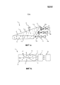
фиг.1а и 1b схематично изображают осветительное устройство в соответствии с вариантом осуществления настоящего изобретения;figa and 1b schematically depict a lighting device in accordance with an embodiment of the present invention;
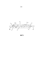
фиг.2 схематично изображает принцип работы настоящего изобретения;figure 2 schematically depicts the principle of operation of the present invention;
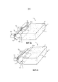
фиг.3а и 3b схематично изображают варианты осуществления осветительного устройства в соответствии с вариантом осуществления настоящего изобретения, содержащего по меньшей мере один коллиматор;figa and 3b schematically depict embodiments of a lighting device in accordance with an embodiment of the present invention containing at least one collimator;
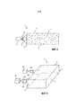
фиг.4 схематично изображает вид сбоку осветительного устройства в соответствии с вариантом осуществления настоящего изобретения, содержащего оптический блок;4 schematically depicts a side view of a lighting device in accordance with an embodiment of the present invention, comprising an optical unit;
фиг.5 схематично изображает вариант осуществления осветительного устройства в соответствии с вариантом осуществления настоящего изобретения, содержащего оптические блоки. 5 schematically depicts an embodiment of a lighting device in accordance with an embodiment of the present invention comprising optical units.
Как показано на чертежах, размеры различных элементов являются в иллюстративных целях преувеличенными и, таким образом, указаны для того, чтобы проиллюстрировать общие конструкции вариантов осуществления настоящего изобретения.As shown in the drawings, the dimensions of the various elements are exaggerated for illustrative purposes and are thus indicated in order to illustrate the general construction of embodiments of the present invention.
Осуществление изобретенияThe implementation of the invention
Теперь настоящее изобретение будет описано далее более подробно со ссылками на сопроводительные чертежи, на которых показаны иллюстративные варианты осуществления настоящего изобретения. Однако настоящее изобретение может быть реализовано во многих иных формах и не должно рассматриваться как ограниченное приведенными далее вариантами осуществления, как раз наоборот, эти варианты осуществления приведены в качестве примерных, так что это описание специалистам в данной области выразит объем изобретения. Далее, по всему описанию одинаковые ссылочные позиции относятся к одним и тем же или подобным элементам или компонентам. The present invention will now be described in more detail below with reference to the accompanying drawings, in which illustrative embodiments of the present invention are shown. However, the present invention can be implemented in many other forms and should not be construed as limited by the following embodiments, but rather, on the contrary, these embodiments are exemplary, so that this description will express the scope of the invention to specialists in this field. Further, throughout the description, the same reference numerals refer to the same or similar elements or components.
Фиг.1а схематично изображает осветительное устройство 1, сконфигурированное для создания выходного света 11. Это осветительное устройство 1 содержит множество светоиспускающих элементов 6а, 6b, 6с, множество модулей 7а, 7b, 7с выбора светового угла и световод 2. Модули 7а, 7b, 7с выбора светового угла установлены для того, чтобы вводить входные световые пучки 10а, 10b, 10с из светоиспускающих элементов 6а, 6b, 6с в световод 2. Световод 2 сконфигурирован с возможностью приема входных световых пучков 10а, 10b, 10с и вывода их в виде выходного света 11. Интервал углов падения входных световых пучков 10а, 10b, 10с определен модулями 7а, 7b, 7с выбора светового угла таким образом, чтобы они были разными для света от соответствующих светоиспускающих элементов 6а, 6b, 6с, введенного в световод 2. Угол падения означает угол между световым лучом, падающим на световую поверхность 3 ввода, и линией, перпендикулярной этой световой поверхности 3 ввода в точке падения светового луча, то есть поверхностью, нормальной к световой поверхности 3 ввода в точке падения светового луча. На показанном примере максимальная величина углов падения входного светового пучка 10а из первого светоиспускающего элемента 6а меньше, чем максимальная величина углов падения входных световых пучков 10b, 10с из второго и третьего светоиспускающих элементов 6а, 6b. Другими словами, средняя величина углов падения световых лучей внутри каждого входного светового пучка 10а, 10b, 10с сконфигурирована таким образом, чтобы быть другой. Fig. 1a schematically depicts a
Фиг.1b схематично изображает показанное на фиг.1а осветительное устройство 1 на виде сбоку, отличном от вида на фиг.1а, при этом светоиспускающие элементы указаны ссылочными поз.6, а модули выбора светового угла указаны ссылочными поз.7. Fig. 1b schematically depicts the
Светоиспускающие элементы 6, 6а, 6b, 6с, в принципе, могут содержать любой тип элемента, который способен порождать и испускать свет. Например, светоиспускающие элементы 6, 6а, 6b, 6с могут содержать светоизлучающие диоды - светодиоды. RGB-светодиоды с успехом используются для обеспечения динамического светового выхода из осветительного устройства 1. Множество, то есть два или более, светоиспускающих элементов 6, 6а, 6b, 6с внутри осветительного устройства 1 в соответствии с настоящим изобретением могут быть одного и того же типа или различных типов. The
На фиг.1а и 1b световод 2 содержит волновод, который сконфигурирован для приема входного света 10 через световую поверхность 3 ввода или посредством ее и для вывода света через световую поверхность 4 вывода или посредством ее. В предпочтительном варианте осуществления, как показано на фиг.1а и 1b, световод 2 выполнен по существу в форме пластины, имеющей торцевые поверхности вдоль ее краев, а также верхнюю поверхность и нижнюю поверхность. Верхняя и нижняя поверхности параллельны между собой. Световая поверхность 3 ввода выполнена на по меньшей мере одной из торцевых поверхностей и является перпендикулярной верхней и нижней поверхностям. Световая поверхность 4 вывода выполнена на верхней и нижней поверхностях. Световод 2 альтернативно может быть образован различными другими способами. Например, он может иметь искривленную конфигурацию, имеющую криволинейные верхнюю и нижнюю поверхности, может иметь более стержнеобразную форму, может иметь треугольную, круговую или любую другую правильную или неправильную форму. Альтернативно, световая поверхность 4 вывода может быть выполнена либо на верхней, либо на нижней поверхности.On figa and 1b, the
Световод 2 сконфигурирован с возможностью обеспечения распространения введенного в него света посредством полного внутреннего отражения. Он содержит материал, через который свет может распространяться. Этот материал, предпочтительно, является прозрачным материалом. Примеры такого материала включают в себя прозрачные акриловые материалы, такие как полиметилметакрилат (ПММА), поликарбонат, стекло и силиконовый каучук.The
В волновод введены светорассеивающие и/или отражающие частицы. Эти частицы 5 обуславливают вывод света в виде выходного света 11. Светорассеивающие и/или отражающие частицы 5 перенаправляют световые пучки, которые падают на них, и могут перенаправлять по меньшей мере некоторые из этих световых пучков в направлении световой поверхности 4 вывода под углом падения, который меньше, чем критический угол падения полного внутреннего отражения, обуславливая таким образом вывод светового пучка из световой поверхности 4 вывода световода 2.Light scattering and / or reflecting particles are introduced into the waveguide. These
Модули 7а, 7b, 7с выбора светового угла выполнены с возможностью приема света, испущенного светоиспускающими элементами 6а, 6b, 6с. Кроме того, они сконфигурированы для испускания света таким образом, чтобы по меньшей мере часть выходного света вводилась в световую поверхность 3 ввода световода 2.The light
Модули 7а, 7b, 7с выбора светового угла дополнительно выполнены с возможностью выбирать или адаптировать световые лучи, испущенные из светоиспускающих элементов 6а, 6b, 6с, таким образом, чтобы в световод 2 вводились только лучи, находящиеся в определенном интервале углов падения. The light
Изменение интервала углов падения различных входных световых пучков 10а, 10b, 10с делает возможным регулировку вывода света из световода 2. Принцип этого схематично показан на фиг.2. Эта иллюстрация показывает два примера световых лучей 110а и 110b, исходящих из светоиспускающих элементов 6а, 6b. Поскольку световая поверхность 3 ввода является по существу плоской поверхностью, то поверхность, нормальная в каждой точке к поверхности ввода, - приблизительно одна и та же. Пример поверхности, нормальной к поверхности 3 ввода, показан пунктирными линиями. Световой луч 110а введен в световод 2 под небольшим углом αа относительно нормали к поверхности, то есть под небольшим углом падения. Световой луч 110b введен в световод 2 под большим углом падения αb. Световые лучи 110а и 110b проходят внутри световода вследствие полного внутреннего отражения. В случае, изображенном на фиг.2, общее расстояние, которое оба луча 110а и 110b прошли внутри световода, по существу одно и то же. Однако световой луч 110а прошел гораздо дальше в световод 2, чем световой луч 110b. Этот световой луч 110b с большим углом падения αb, чем угол падения αа светового луча 110а, делает большее количество отражений внутри световода 2, и поэтому не распространяется в световоде 2 так же далеко, как и световой луч 110а, хотя в случае, изображенном на фиг.2, эти световые лучи 110а и 110b прошли внутри световода по существу одно и то же расстояние. Changing the interval of angles of incidence of various
Количество света, которое выведено из световода 2, является функцией расстояния прохождения или распространения в световоде 2. Поэтому световой луч 110b с большим углом падения αb будет выведен из световода 2 быстрее, чем световые лучи 110а с меньшим углом падения αа. Световые лучи 110а с меньшим углом падения αа будут выведены более "медленно" и, таким образом, будут в состоянии проникнуть дальше в световод 2, прежде чем будут выведены. Соответственно, световые лучи, имеющие относительно большее количество световых лучей с большим углом падения α, будут выведены из световода 2 "быстрее", чем световые лучи 110а, имеющие относительно большее количество световых лучей с меньшим углом падения α.The amount of light that is extracted from the
Одним из способов регулирования интервала углов падения светового луча является использование коллиматора. На фиг.1а входной световой пучок 10а, испущенный из светоиспускающего элемента 6а, коллимируется в большей степени, чем входной световой пучок 10с, испущенный из светоиспускающего элемента 6с. Чем больше коллимирован свет, тем больше в нем относительного количества световых лучей, имеющих малые углы падения α. Соответственно, более коллимированный свет будет в большей степени проникать в световод, чем менее коллимированный свет. Как проиллюстрировано на фиг.1, входной световой пучок 10а, испущенный из светоиспускающего элемента 6а, таким образом, проникнет в световод 2 дальше, чем входной световой пучок 10с, испущенный из светоиспускающего элемента 6с. Входной световой пучок 10а, кроме того, будет выведен из световода 2 более "медленно", чем входной световой пучок 10b, и, таким образом, будет менее интенсивным. Для того чтобы компенсировать это, интенсивность более коллимированного светового пучка 10а может быть увеличена. Коллимация света позволяет также производить увеличение интенсивности входного светового пучка 10 с меньшим риском получения ярких световых пятен, появляющихся на стороне ввода света световода.One way to control the interval of angles of incidence of a light beam is to use a collimator. 1a, the
Изменением коллимации входного светового пучка 10, таким образом, можно регулировать расстояние, которое свет проходит в световоде 2 от поверхности 3 ввода света, прежде чем он будет выведен. Другими словами, степень коллимации может быть использована для изменения расстояния, которое свет проходит внутри световода 2. Чем больше коллимирован свет, тем дальше он пройдет по световоду 2 и тем "медленнее" будет выведен из поверхности 4 вывода света. Другими словами, чем больше коллимирован свет, тем дальше он пройдет внутри световода 2 и тем меньше выходная эффективность света. Это может быть использовано, например, для достижения равномерного светового выхода из световода, имеющего такую форму, в которой длина пути или расстояние проникновения для света от поверхности 3 ввода света изменяется. Фиг.1 показывает такое осветительное устройство 1 со световодом 2, которое является треугольным. Расстояние, которое на фиг.1 условно обозначено L1, которое свет должен пройти, чтобы быть выведенным после прохождения существу полной длины световода 2, является более длинным для входного светового пучка 10а, испущенного из светоиспускающего элемента 6а у основания треугольника, чем для входных световых пучков 10b и 10с, испущенных из светоиспускающих элементов 6b и 6с, соответственно, в середине и у вершины треугольника. Конфигурированием входного светового пучка 10а таким образом, чтобы он был наиболее коллимированным, входного светового пучка 10b, чтобы он был менее коллимированным, и входного светового пучка 10с, чтобы он был наименее коллимированным, свет у наибольшей стороны треугольника (обозначенной L1) пройдет дальше в световод 2, чем свет в середине (обозначено L2) и у вершины (обозначено L3) треугольника. Вследствие коллимации свет будет равномерно испускаться по всей длине L в трех местах треугольника, включая длинное основание. Тем самым достигнут равномерный выходной свет 11. Меньшая степень светового вывода для более коллимированного света может быть компенсирована увеличением на соответствующую величину интенсивности входного светового пучка 10. Таким образом, дальнейшим конфигурированием входного светового пучка 10а, так, чтобы он был более интенсивным, входного светового пучка 10b, чтобы он был менее интенсивным, и входного светового пучка 10с, чтобы он был менее интенсивным, выходной свет 11 может быть сделан еще более равномерным.By changing the collimation of the
Специалист в данной области поймет, что равномерное выходное свечение световода 2 треугольной или иной неправильной формы может быть соответствующим образом организовано посредством использования модулей световой селекции другого типа, таких как описанные далее модули 8 блокировки света.One of ordinary skill in the art will recognize that a uniform output glow of a triangular or other
Фиг.3а показывает схематичный вариант осуществления осветительного устройства 1 в соответствии с настоящим изобретением, которое содержит два светоиспускающих элемента 6а, 6b и световод 2. Этот световод 2 содержит светорассеивающие и/или отражающие частицы 5 и выполнен с возможностью принимать входной свет 10 от светоиспускающих элементов 6а, 6b через световую поверхность 3 ввода или посредством ее. Световое устройство 1 дополнительно содержит два коллиматора 7а, 7b, которые выполнены с возможностью коллимации входных световых пучков 10а, 10b от соответствующих светоиспускающих элементов 6а, 6b, прежде чем свет будет введен в световод 2 через световую поверхность 3 ввода. Коллиматоры 7а, 7b отражают свет от светоиспускающих элементов 6а, 6b таким образом, что он становится более параллельным поверхности, нормальной к световой поверхности 3 ввода, то есть, таким образом, что он становится более коллимированным в направлении, которое по существу перпендикулярно поверхности, нормальной к световой поверхности 3 ввода. Тем самым средний угол падения α их световых лучей уменьшается. Коллиматор 7а выполнен с возможностью коллимации света в большей степени, чем коллиматор 7b посредством перенаправления света в направлении поверхности, нормальной в большей степени. Fig. 3a shows a schematic embodiment of a
Фиг.3b показывает подобный же вариант осуществления, в котором используется один коллиматор 7 для обеспечения различной коллимации света, испущенного от светоиспускающих элементов 6а, 6b. Этот один коллиматор 7b по разному перенаправляет входные световые пучки 10а, 10b от двух светоиспускающих элементов 6а, 6b посредством плавного изменения угла перенаправления. Тем самым достигается плавное изменение в степени коллимации при переходе от входного светового пучка 10b, испущенного светоиспускающим элементом 6b, к входному световому пучку 10а, испущенному светоиспускающим элементом 6а. Fig. 3b shows a similar embodiment in which one
Следует понимать, что в осветительном устройстве 1 по настоящему изобретению может быть использовано большее количество светоиспускающих элементов 6 и/или коллиматоров 7, чем показано на фиг.3а и 3b, Следует понимать также, что степень коллимации не обязательно постепенно увеличивать или уменьшать вдоль световой поверхности 3 ввода световода 2. Когда световод 2 имеет неправильную форму, или если есть другая причина для того, чтобы требовать различного светового выхода вдоль световода 2, тогда вдоль световода 2 могут быть расположены, соответственно, один или большее количество коллиматоров 7, обеспечивающих различную степень коллимации. Это также действительно для вариантов осуществления, в которых различные степени коллимации обеспечиваются посредством других элементов регулировки коллимации, а не коллиматорами, такими как отражатели, рефракторы, оптические блоки или способами дифракции, такими как с линзами Френеля. It should be understood that in the
Изменение интервала угла падения для входных световых пучков 10 от разных светоиспускающих элементов 6 в альтернативном варианте осуществления может быть достигнуто предотвращением ввода в световод света, идущего под некоторыми углами падения α, например, посредством светового блокиратора, такого как оптический блок. Фиг.4 показывает пример, в котором перед светоиспускающим элементом 6 помещен модуль выбора светового угла в виде модуля 8 блокировки света. Этот модуль 8 блокировки света препятствует вводу в световод световых лучей внутри интервала малых углов падения α. Только лучи с большим углом падения α могут пройти модуль 8 блокировки света и, таким образом, могут быть введены в световод 2. Поскольку результирующий входной световой пучок 10 содержит большую часть световых лучей с большим углом падения α, он пройдет в световод 2 на короткое расстояние. Таким образом, такой модуль 8 блокировки света подходит для обеспечения света с более низкой степенью коллимации, для света, для которого не требуется глубокое проникновение в световод 2.Changing the incidence angle interval for the input light beams 10 from different
Для того чтобы достичь разных интервалов углов падения для света, испущенного из двух или более светоиспускающих элементов 6, один модуль 8 блокировки света может быть использован таким образом, чтобы был блокирован свет лишь от одного из светоиспускающих элементов 6, но не от другого. Как показано на фиг.5, альтернативно, могут быть использованы два или более модулей 8 блокировки света или один модуль 8 блокировки света для каждого светоиспускающего элемента. В этом случае оптические блоки 8 устанавливают таким образом, чтобы соответствующие модули 8 блокировки света блокировали световые лучи различных интервалов углов падения α, например, будучи разными по размерам. В другом варианте осуществления один модуль 8 блокировки света может быть использован, чтобы по разному блокировать свет от разных светоиспускающих элементов 6. Такой один модуль 8 блокировки света может быть сконфигурирован таким образом, чтобы обеспечивать переменную степень блокировки, например, имея постепенное изменение размеров, так чтобы световые лучи интервала больших углов падения были бы блокированы на первом конце модуля 8 блокировки света, а интервал меньших углов падения был бы блокирован на втором конце модуля 8 блокировки света. In order to achieve different ranges of incidence angles for the light emitted from two or more
В заключение - раскрыто осветительное устройство, содержащее световод с введенными светорассеивающими и/или отражающими частицами, первый светоиспускающий элемент и второй светоиспускающий элемент. Осветительное устройство сконфигурировано таким образом, что для световых лучей, испущенных первым светоиспускающим элементом, углы падения световых лучей, введенных в световод, находятся внутри первого углового интервала, и таким образом, что для световых лучей, испущенных вторым светоиспускающим элементом, углы падения световых лучей, введенных в световод, находятся внутри второго углового интервала, при этом первый угловой интервал и второй угловой интервал различны. Обеспечено осветительное устройство, в котором количество света, который выведен из световода, в выбранном месте может быть адаптировано в соответствии с требуемым, например, для того, чтобы дать равномерное освещение.In conclusion, a lighting device is disclosed comprising a light guide with light diffusing and / or reflecting particles introduced, a first light emitting element and a second light emitting element. The lighting device is configured so that for the light rays emitted by the first light emitting element, the angles of incidence of the light rays introduced into the light guide are inside the first angular interval, and so that for the light rays emitted by the second light emitting element, the angles of incidence of the light rays, introduced into the fiber, are inside the second angular interval, while the first angular interval and the second angular interval are different. A lighting device is provided in which the amount of light that is removed from the light guide at a selected location can be adapted as desired, for example, in order to give uniform illumination.
Хотя настоящее изобретение было подробно проиллюстрировано и описано в приложенных чертежах и в вышеприведенном описании, такая иллюстрация и описание должны рассматриваться как иллюстративные или примерные, а не ограничивающие: настоящее изобретение не сводится к раскрытым вариантам осуществления. Специалистами в данной области, имеющими практическое отношение к заявленному изобретению, в результате изучения чертежей, описания и приложенных пунктов формулы изобретения могут быть придуманы и введены другие изменения в раскрытые варианты осуществления. Тот простой факт, что некоторые критерии упоминаются во взаимно различных зависимых пунктах формулы изобретения, не означает, что для получения положительного эффекта не может быть использована комбинация этих критериев. Любые ссылочные позиции в пунктах формулы изобретения не должны истолковываться как ограничивающие ее объем.Although the present invention has been illustrated and described in detail in the accompanying drawings and in the above description, such illustration and description should be considered as illustrative or exemplary, and not limiting: the present invention is not limited to the disclosed embodiments. Specialists in this field, having a practical relationship to the claimed invention, as a result of studying the drawings, description and appended claims, other changes to the disclosed embodiments may be devised and introduced. The simple fact that some criteria are mentioned in mutually different dependent claims does not mean that a combination of these criteria cannot be used to obtain a positive effect. Any reference positions in the claims should not be construed as limiting its scope.
Claims (19)
Applications Claiming Priority (3)
| Application Number | Priority Date | Filing Date | Title |
|---|---|---|---|
| US201261695809P | 2012-08-31 | 2012-08-31 | |
| US61/695,809 | 2012-08-31 | ||
| PCT/IB2013/056833 WO2014033602A2 (en) | 2012-08-31 | 2013-08-23 | Illumination device based on light guide with light scattering particles and light angle selection module |
Publications (2)
| Publication Number | Publication Date |
|---|---|
| RU2015111537A RU2015111537A (en) | 2016-10-20 |
| RU2638822C2 true RU2638822C2 (en) | 2017-12-18 |
Family
ID=49622849
Family Applications (1)
| Application Number | Title | Priority Date | Filing Date |
|---|---|---|---|
| RU2015111537A RU2638822C2 (en) | 2012-08-31 | 2013-08-23 | Lighting device based on light guide with light-scattering particles and light angle selection module |
Country Status (6)
| Country | Link |
|---|---|
| US (1) | US20150205031A1 (en) |
| EP (1) | EP2890928A2 (en) |
| JP (1) | JP2015528634A (en) |
| CN (1) | CN104583672A (en) |
| RU (1) | RU2638822C2 (en) |
| WO (1) | WO2014033602A2 (en) |
Families Citing this family (3)
| Publication number | Priority date | Publication date | Assignee | Title |
|---|---|---|---|---|
| NZ743790A (en) * | 2016-01-12 | 2023-01-27 | Magic Leap Inc | Beam angle sensor in virtual/augmented reality system |
| US10955607B2 (en) * | 2017-03-07 | 2021-03-23 | Lumileds Llc | LED lighting device with remote phosphor in-coupling structure for in-coupling light from light emitting diodes |
| KR102116173B1 (en) | 2018-01-12 | 2020-05-28 | 제트카베 그룹 게엠베하 | Lamp for vehicle and vehicle |
Citations (9)
| Publication number | Priority date | Publication date | Assignee | Title |
|---|---|---|---|---|
| RU2324960C2 (en) * | 2002-03-21 | 2008-05-20 | Лумус Лтд. | Light-conducting optical element |
| US20090135625A1 (en) * | 2007-11-27 | 2009-05-28 | Sony Corporation | Display device and optical device |
| RU2358301C2 (en) * | 2003-09-10 | 2009-06-10 | Лумус Лтд. | Optical devices with light guide substrate |
| US20090147533A1 (en) * | 2007-12-06 | 2009-06-11 | Kee Tae Um | Display Device |
| WO2010049912A2 (en) * | 2008-10-31 | 2010-05-06 | Udayan Kanade | A light source with light recovery mechanism |
| US20110096570A1 (en) * | 2008-05-30 | 2011-04-28 | Koninklijke Philips Electronics N.V. | Illumination device comprising a light guide |
| RU2431168C2 (en) * | 2008-07-11 | 2011-10-10 | Корпорация "САМСУНГ ЭЛЕКТРОНИКС Ко., Лтд." | Illumination device |
| US20120106193A1 (en) * | 2010-10-29 | 2012-05-03 | Kim Guk-Hyun | Backlight assembly and display apparatus having the same |
| US20120120678A1 (en) * | 2010-11-15 | 2012-05-17 | Young Lighting Technology Corporation | Backlight module |
Family Cites Families (10)
| Publication number | Priority date | Publication date | Assignee | Title |
|---|---|---|---|---|
| JP3551187B2 (en) * | 2002-11-28 | 2004-08-04 | セイコーエプソン株式会社 | Optical element, illumination device, and projection display device |
| WO2006129220A1 (en) * | 2005-05-30 | 2006-12-07 | Koninklijke Philips Electronics N.V. | Light-emitting device with brightness enhancing layer |
| JP4823636B2 (en) * | 2005-10-13 | 2011-11-24 | ハリソン東芝ライティング株式会社 | Lighting device |
| WO2007057819A1 (en) * | 2005-11-21 | 2007-05-24 | Koninklijke Philips Electronics N.V. | Lighting device |
| US7901125B2 (en) * | 2006-01-23 | 2011-03-08 | Fujifilm Corporation | Wedge-shaped lighting device |
| US8475010B2 (en) * | 2008-05-30 | 2013-07-02 | Koninklijke Philips Electronics N.V. | Illumination device comprising a collimator |
| CA2726151C (en) | 2008-05-30 | 2016-11-22 | Koninklijke Philips Electronics N.V. | Round illumination device |
| KR101621013B1 (en) * | 2008-12-09 | 2016-05-16 | 삼성디스플레이 주식회사 | Display device |
| JP2011060685A (en) * | 2009-09-14 | 2011-03-24 | Panasonic Corp | Light source unit |
| KR20120088121A (en) * | 2011-01-31 | 2012-08-08 | 삼성전자주식회사 | Backlight assembly and display apparatus having the same |
-
2013
- 2013-08-23 RU RU2015111537A patent/RU2638822C2/en not_active IP Right Cessation
- 2013-08-23 JP JP2015529164A patent/JP2015528634A/en active Pending
- 2013-08-23 WO PCT/IB2013/056833 patent/WO2014033602A2/en active Application Filing
- 2013-08-23 US US14/423,341 patent/US20150205031A1/en not_active Abandoned
- 2013-08-23 EP EP13792976.6A patent/EP2890928A2/en not_active Withdrawn
- 2013-08-23 CN CN201380044980.9A patent/CN104583672A/en active Pending
Patent Citations (9)
| Publication number | Priority date | Publication date | Assignee | Title |
|---|---|---|---|---|
| RU2324960C2 (en) * | 2002-03-21 | 2008-05-20 | Лумус Лтд. | Light-conducting optical element |
| RU2358301C2 (en) * | 2003-09-10 | 2009-06-10 | Лумус Лтд. | Optical devices with light guide substrate |
| US20090135625A1 (en) * | 2007-11-27 | 2009-05-28 | Sony Corporation | Display device and optical device |
| US20090147533A1 (en) * | 2007-12-06 | 2009-06-11 | Kee Tae Um | Display Device |
| US20110096570A1 (en) * | 2008-05-30 | 2011-04-28 | Koninklijke Philips Electronics N.V. | Illumination device comprising a light guide |
| RU2431168C2 (en) * | 2008-07-11 | 2011-10-10 | Корпорация "САМСУНГ ЭЛЕКТРОНИКС Ко., Лтд." | Illumination device |
| WO2010049912A2 (en) * | 2008-10-31 | 2010-05-06 | Udayan Kanade | A light source with light recovery mechanism |
| US20120106193A1 (en) * | 2010-10-29 | 2012-05-03 | Kim Guk-Hyun | Backlight assembly and display apparatus having the same |
| US20120120678A1 (en) * | 2010-11-15 | 2012-05-17 | Young Lighting Technology Corporation | Backlight module |
Also Published As
| Publication number | Publication date |
|---|---|
| US20150205031A1 (en) | 2015-07-23 |
| EP2890928A2 (en) | 2015-07-08 |
| WO2014033602A3 (en) | 2014-05-30 |
| RU2015111537A (en) | 2016-10-20 |
| CN104583672A (en) | 2015-04-29 |
| WO2014033602A2 (en) | 2014-03-06 |
| JP2015528634A (en) | 2015-09-28 |
Similar Documents
| Publication | Publication Date | Title |
|---|---|---|
| US8807816B2 (en) | Luminaire with Functionality-enhancing structure | |
| JP5530426B2 (en) | Illumination device having a collimator | |
| US9322970B2 (en) | Optical system for coupling light from point light sources into a flat light guide | |
| US9121982B2 (en) | Light-emitting device for emitting diffuse light | |
| KR20160138984A (en) | Asymmetric turning film with multiple light sources | |
| JP2004310002A (en) | Light guiding plate | |
| KR20120066658A (en) | Light-emitting device | |
| CN107667255B (en) | Illumination system and illumination method using light guide | |
| JP6214151B2 (en) | Lighting device | |
| CZ2001620A3 (en) | Lamp | |
| RU2638822C2 (en) | Lighting device based on light guide with light-scattering particles and light angle selection module | |
| WO2014033576A1 (en) | Illumination device based on light guide with light diffusing particles | |
| JP2005539356A (en) | Light emitting device having light input and light output unit | |
| CN113710952B (en) | Light emitting device | |
| JP2006202559A (en) | Surface light source apparatus | |
| WO2019157501A1 (en) | Luminaires for spatial dimming | |
| CN109477627B (en) | Lighting system using light guiding structure | |
| JP6285220B2 (en) | LIGHTING DEVICE AND LIGHTING APPARATUS HAVING THE SAME | |
| RU2575320C2 (en) | Light-emitting system for emission of scattered light | |
| JP2004139901A (en) | Lighting device | |
| KR20160059552A (en) | Back light unit | |
| JP2016201203A (en) | Luminaire |
Legal Events
| Date | Code | Title | Description |
|---|---|---|---|
| HZ9A | Changing address for correspondence with an applicant | ||
| MM4A | The patent is invalid due to non-payment of fees |
Effective date: 20180824 |