JP2015528634A - Lighting device based on light guide with light scattering particles and light angle selection module - Google Patents
Lighting device based on light guide with light scattering particles and light angle selection module Download PDFInfo
- Publication number
- JP2015528634A JP2015528634A JP2015529164A JP2015529164A JP2015528634A JP 2015528634 A JP2015528634 A JP 2015528634A JP 2015529164 A JP2015529164 A JP 2015529164A JP 2015529164 A JP2015529164 A JP 2015529164A JP 2015528634 A JP2015528634 A JP 2015528634A
- Authority
- JP
- Japan
- Prior art keywords
- light
- angle
- emitting element
- light emitting
- lighting device
- Prior art date
- Legal status (The legal status is an assumption and is not a legal conclusion. Google has not performed a legal analysis and makes no representation as to the accuracy of the status listed.)
- Pending
Links
Images


Classifications
-
- G—PHYSICS
- G02—OPTICS
- G02B—OPTICAL ELEMENTS, SYSTEMS OR APPARATUS
- G02B6/00—Light guides; Structural details of arrangements comprising light guides and other optical elements, e.g. couplings
- G02B6/0001—Light guides; Structural details of arrangements comprising light guides and other optical elements, e.g. couplings specially adapted for lighting devices or systems
- G02B6/0011—Light guides; Structural details of arrangements comprising light guides and other optical elements, e.g. couplings specially adapted for lighting devices or systems the light guides being planar or of plate-like form
- G02B6/0013—Means for improving the coupling-in of light from the light source into the light guide
- G02B6/0023—Means for improving the coupling-in of light from the light source into the light guide provided by one optical element, or plurality thereof, placed between the light guide and the light source, or around the light source
-
- G—PHYSICS
- G02—OPTICS
- G02B—OPTICAL ELEMENTS, SYSTEMS OR APPARATUS
- G02B6/00—Light guides; Structural details of arrangements comprising light guides and other optical elements, e.g. couplings
- G02B6/0001—Light guides; Structural details of arrangements comprising light guides and other optical elements, e.g. couplings specially adapted for lighting devices or systems
- G02B6/0011—Light guides; Structural details of arrangements comprising light guides and other optical elements, e.g. couplings specially adapted for lighting devices or systems the light guides being planar or of plate-like form
- G02B6/0033—Means for improving the coupling-out of light from the light guide
- G02B6/0035—Means for improving the coupling-out of light from the light guide provided on the surface of the light guide or in the bulk of it
- G02B6/004—Scattering dots or dot-like elements, e.g. microbeads, scattering particles, nanoparticles
- G02B6/0041—Scattering dots or dot-like elements, e.g. microbeads, scattering particles, nanoparticles provided in the bulk of the light guide
-
- G—PHYSICS
- G02—OPTICS
- G02B—OPTICAL ELEMENTS, SYSTEMS OR APPARATUS
- G02B6/00—Light guides; Structural details of arrangements comprising light guides and other optical elements, e.g. couplings
- G02B6/0001—Light guides; Structural details of arrangements comprising light guides and other optical elements, e.g. couplings specially adapted for lighting devices or systems
- G02B6/0011—Light guides; Structural details of arrangements comprising light guides and other optical elements, e.g. couplings specially adapted for lighting devices or systems the light guides being planar or of plate-like form
- G02B6/0013—Means for improving the coupling-in of light from the light source into the light guide
- G02B6/0023—Means for improving the coupling-in of light from the light source into the light guide provided by one optical element, or plurality thereof, placed between the light guide and the light source, or around the light source
- G02B6/0028—Light guide, e.g. taper
-
- G—PHYSICS
- G02—OPTICS
- G02B—OPTICAL ELEMENTS, SYSTEMS OR APPARATUS
- G02B6/00—Light guides; Structural details of arrangements comprising light guides and other optical elements, e.g. couplings
- G02B6/0001—Light guides; Structural details of arrangements comprising light guides and other optical elements, e.g. couplings specially adapted for lighting devices or systems
- G02B6/0011—Light guides; Structural details of arrangements comprising light guides and other optical elements, e.g. couplings specially adapted for lighting devices or systems the light guides being planar or of plate-like form
- G02B6/0013—Means for improving the coupling-in of light from the light source into the light guide
- G02B6/0023—Means for improving the coupling-in of light from the light source into the light guide provided by one optical element, or plurality thereof, placed between the light guide and the light source, or around the light source
- G02B6/003—Lens or lenticular sheet or layer
-
- G—PHYSICS
- G02—OPTICS
- G02B—OPTICAL ELEMENTS, SYSTEMS OR APPARATUS
- G02B6/00—Light guides; Structural details of arrangements comprising light guides and other optical elements, e.g. couplings
- G02B6/0001—Light guides; Structural details of arrangements comprising light guides and other optical elements, e.g. couplings specially adapted for lighting devices or systems
- G02B6/0011—Light guides; Structural details of arrangements comprising light guides and other optical elements, e.g. couplings specially adapted for lighting devices or systems the light guides being planar or of plate-like form
- G02B6/0013—Means for improving the coupling-in of light from the light source into the light guide
- G02B6/0023—Means for improving the coupling-in of light from the light source into the light guide provided by one optical element, or plurality thereof, placed between the light guide and the light source, or around the light source
- G02B6/0031—Reflecting element, sheet or layer
-
- G—PHYSICS
- G02—OPTICS
- G02B—OPTICAL ELEMENTS, SYSTEMS OR APPARATUS
- G02B6/00—Light guides; Structural details of arrangements comprising light guides and other optical elements, e.g. couplings
- G02B6/0001—Light guides; Structural details of arrangements comprising light guides and other optical elements, e.g. couplings specially adapted for lighting devices or systems
- G02B6/0011—Light guides; Structural details of arrangements comprising light guides and other optical elements, e.g. couplings specially adapted for lighting devices or systems the light guides being planar or of plate-like form
- G02B6/0033—Means for improving the coupling-out of light from the light guide
- G02B6/0035—Means for improving the coupling-out of light from the light guide provided on the surface of the light guide or in the bulk of it
- G02B6/0045—Means for improving the coupling-out of light from the light guide provided on the surface of the light guide or in the bulk of it by shaping at least a portion of the light guide
-
- G—PHYSICS
- G02—OPTICS
- G02B—OPTICAL ELEMENTS, SYSTEMS OR APPARATUS
- G02B6/00—Light guides; Structural details of arrangements comprising light guides and other optical elements, e.g. couplings
- G02B6/0001—Light guides; Structural details of arrangements comprising light guides and other optical elements, e.g. couplings specially adapted for lighting devices or systems
- G02B6/0011—Light guides; Structural details of arrangements comprising light guides and other optical elements, e.g. couplings specially adapted for lighting devices or systems the light guides being planar or of plate-like form
- G02B6/0066—Light guides; Structural details of arrangements comprising light guides and other optical elements, e.g. couplings specially adapted for lighting devices or systems the light guides being planar or of plate-like form characterised by the light source being coupled to the light guide
- G02B6/0068—Arrangements of plural sources, e.g. multi-colour light sources
Abstract
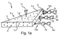
埋め込まれた光散乱及び/又は反射粒子5を有するライトガイド2と、第1の発光要素6aと、第2の発光要素6bとを含む照明デバイス1が開示される。照明デバイス1は、第1の発光要素6aによって放射される光線について、ライトガイド2内へと入力される光線の入射角が、第1の角度区間内にあり、第2の発光要素6bによって放射される光線について、ライトガイド2内へと入力される光線の入射角が、第2の角度区間内にあるように構成され、第1の角度区間と第2の角度区間とは異なる。例えば均一の照明を与えるために、選択された位置においてライトガイド2から出力される光の量が要望通りに適応される照明デバイス1が提供される。An illumination device 1 is disclosed that includes a light guide 2 having embedded light scattering and / or reflective particles 5, a first light emitting element 6a, and a second light emitting element 6b. The illumination device 1 has the incident angle of the light beam input into the light guide 2 within the first angle section for the light beam emitted by the first light emitting element 6a, and is emitted by the second light emitting element 6b. The incident angle of the light beam input into the light guide 2 is configured to be within the second angle section, and the first angle section and the second angle section are different. For example, an illumination device 1 is provided in which the amount of light output from the light guide 2 at a selected location is adapted as desired to provide uniform illumination.
Description
本発明は、光散乱及び/又は反射粒子が埋め込まれたライトガイドと、複数の発光要素と、光角度選択モジュールとを含む照明デバイスに関する。 The present invention relates to a lighting device comprising a light guide embedded with light scattering and / or reflecting particles, a plurality of light emitting elements, and a light angle selection module.
光を内部で伝播し、その表面からの光の方向を転換し出力させることができるライトガイドシート又はプレートに結合される光源を含む照明デバイスは、棚、インテリアパネル、サイン及びポスターといった面を照明するように提供される。 A lighting device that includes a light source coupled to a light guide sheet or plate that can propagate light internally and redirect and output the light from its surface, illuminates surfaces such as shelves, interior panels, signs and posters Provided to be.
このような照明デバイスに使用する1つのライトガイドは、Evonik Industries社から販売されるACRYLITE(登録商標)Endlightenシートである。これは、光拡散粒子が埋め込まれた光伝導アクリル材料シートを含む。アクリルシートは、その端面を介して、光源からの光を受け入れる。端面から、光は、内部反射によってシート内を伝播する。シート内に埋め込まれている光拡散粒子は、移動光の少なくとも一部がシートの表面から出て、シートにその照明特性を与えるように当該移動光の方向を転換する。 One light guide used for such lighting devices is the ACRYLITE® Endlightten sheet sold by Evonik Industries. This includes a photoconductive acrylic material sheet embedded with light diffusing particles. The acrylic sheet receives light from the light source through its end face. From the end face, light propagates in the sheet by internal reflection. The light diffusing particles embedded in the sheet change the direction of the traveling light so that at least a portion of the traveling light exits the surface of the sheet and imparts its illumination characteristics to the sheet.
このようなライトガイドの各位置における輝度は、ライトガイド内の光損失に起因して、当該位置に到着するために光が移動又は伝播しなければならない距離に依存する。これは、1つ以上の光源が位置付けられているライトガイドの端は、光源からより離れた領域よりも明るいという結果となる。更に、光がその中で様々な距離を移動する、例えば不規則な形状及び三角形のライトガイドは、不均一に点灯するという結果にもなる。 The brightness at each position of such a light guide depends on the distance that the light must travel or propagate to reach that position due to light loss in the light guide. This results in the end of the light guide where one or more light sources are positioned brighter than the area further away from the light source. Furthermore, light traveling in various distances within it, for example irregularly shaped and triangular light guides, also results in uneven lighting.
上記に鑑み、本発明の関心事項は、より均一な照明を有する、例えばライトガイドから出力される光の輝度が背景技術のセクションにおいて説明されたライトガイドから出力される光よりもより均質である、又は、ライトガイドから出力される光の輝度が完全に若しくはほぼ完全に均質である、照明デバイスを提供することである。本発明の別の関連する関心事項は、選択された位置におけるライトガイドから出力される光の量が所望通りに適応される照明デバイスを提供することである。 In view of the above, the interest of the present invention has a more uniform illumination, for example the brightness of the light output from the light guide is more homogeneous than the light output from the light guide described in the background section Or providing a lighting device in which the brightness of the light output from the light guide is completely or almost completely homogeneous. Another related concern of the present invention is to provide an illumination device in which the amount of light output from the light guide at selected locations is adapted as desired.
上記の関心事項及び他の関心事項のうちの少なくとも1つに取り組むために、独立請求項に係る照明デバイスが提供される。好適な実施形態は、従属請求項によって規定される。 To address at least one of the above concerns and other concerns, a lighting device according to the independent claims is provided. Preferred embodiments are defined by the dependent claims.
本発明の第1の態様によれば、埋め込まれた光散乱及び/又は反射粒子と、光入力面に衝突する光をライトガイド内へと入力する当該光入力面とを含む当該ライトガイドと、第1の発光要素と、少なくとも第2の発光要素と、を含み、第1の発光要素及び少なくとも第2の発光要素によってそれぞれ放射される光の少なくとも一部が、光入力面に衝突し、照明デバイスは、第1の発光要素によって放射される光線について、光入力面に衝突する光線の入射角が、第1の角度区間内にあり、少なくとも第2の発光要素によって放射される光線について、光入力面に衝突する光線の入射角が、第2の角度区間内にあるように構成され、第1の角度区間と第2の角度区間とは異なる、又は、実質的に異なる、照明デバイスが提供される。 According to a first aspect of the invention, the light guide comprising embedded light scattering and / or reflective particles and the light input surface for inputting light impinging on the light input surface into the light guide; A first light emitting element and at least a second light emitting element, wherein at least part of the light respectively emitted by the first light emitting element and at least the second light emitting element impinges on the light input surface and is illuminated For the light emitted by the first light emitting element, the device has an incident angle of the light that impinges on the light input surface is within the first angular interval, and at least for the light emitted by the second light emitting element. Provided is an illumination device configured such that an incident angle of a light ray impinging on an input surface is within a second angle interval, and the first angle interval and the second angle interval are different or substantially different Is done.
例えば、照明デバイスは、第1の発光要素及び少なくとも第2の発光要素によってそれぞれ放射される光を受け取り、第1の発光要素及び少なくとも第2の発光要素によってそれぞれ放射される光の少なくとも一部が光入力面に衝突するように、光を出力する光角度選択モジュールを含む。光角度選択モジュールは、第1の発光要素によって放射される光線について、光入力面に衝突する光線の入射角が、第1の角度区間内にあり、少なくとも第2の発光要素によって放射される光線について、光入力面に衝突する光線の入射角が、第2の角度区間内にあるように構成される。 For example, the lighting device receives light emitted by a first light emitting element and at least a second light emitting element, respectively, and at least a portion of the light emitted by the first light emitting element and at least the second light emitting element, respectively. A light angle selection module that outputs light so as to collide with the light input surface is included. The light angle selection module has, for the light emitted by the first light emitting element, the incident angle of the light that impinges on the light input surface is within the first angle section, and the light emitted by at least the second light emitting element. Is configured such that the incident angle of the light beam colliding with the light input surface is within the second angle section.
或いは又は任意選択的に、上記の光角度選択機能は、第1の発光要素及び少なくとも第2の発光要素内にそれぞれ提供されてもよい。つまり、第1の発光要素及び少なくとも第2の発光要素はそれぞれ、第1の発光要素及び少なくとも第2の発光要素によってそれぞれ放射される光の少なくとも一部が光入力面に衝突するように、また、第1の発光要素によって放射される光線について、光入力面に衝突する光線の入射角が、第1の角度区間内にあり、少なくとも第2の発光要素によって放射される光線について、光入力面に衝突する光線の入射角が、第2の角度区間内にあるように構成され、第1の角度区間と第2の角度区間とは異なる、又は、大幅に異なる。 Alternatively or optionally, the light angle selection function described above may be provided in each of the first light emitting element and at least the second light emitting element. That is, the first light-emitting element and at least the second light-emitting element are respectively arranged so that at least part of the light emitted by the first light-emitting element and at least the second light-emitting element respectively impinges on the light input surface. For the light emitted by the first light emitting element, the incident angle of the light that impinges on the light input surface is within the first angle interval, and at least for the light emitted by the second light emitting element, the light input surface The incident angle of the light beam that collides with the second angle section is configured to be within the second angle section, and the first angle section and the second angle section are different or significantly different.
以下の説明では、本発明の実施形態は、照明デバイスが上記されたような光角度選択モジュールを含む場合を参照して説明される。しかし、当然ながら、以下に説明される本発明の実施形態はすべて、照明デバイスにおける上記されたような光角度選択機能が、第1の発光要素及び少なくとも第2の発光要素にそれぞれ提供されている、即ち、別個の光角度選択ユニットによってではなくこれらの発光要素に提供されている場合にも対応して適応される。 In the following description, embodiments of the present invention will be described with reference to the case where the lighting device includes a light angle selection module as described above. However, it will be appreciated that all of the embodiments of the invention described below are provided with a light angle selection function as described above in the lighting device, respectively, on the first light emitting element and at least the second light emitting element. I.e. correspondingly provided for these light emitting elements rather than by a separate light angle selection unit.
本明細書において言及される「入射角」との用語は、光入力面に入射する光線と、光線の入射点における光入力面に垂直な線、即ち、光線の入射点における光入力面の面法線との間の角度を表す。 As used herein, the term “incident angle” refers to a light ray incident on the light input surface and a line perpendicular to the light input surface at the light incident point, ie, the surface of the light input surface at the light incident point. Represents the angle to the normal.
一実施形態では、光角度選択モジュールは、第1の発光要素によって放射される光線について、少なくとも1つの平面に対して光入力面に衝突する光線の入射角が、第1の角度区間内にあり、少なくとも第2の発光要素によって放射される光線について、当該少なくとも1つの平面に対して光入力面に衝突する光線の入射角が、第2の角度区間内にあるように構成され、当該少なくとも1つの平面は、光入力面の面法線及び光入力面の面法線に直交する方向によって画定される。例えば、ライトガイド内へと入力される光は、1つの方向においてのみコリメートされる。 In one embodiment, the light angle selection module has an incident angle of a light ray that impinges on the light input surface with respect to at least one plane within the first angle interval for the light ray emitted by the first light emitting element. , At least for the light rays emitted by the second light emitting element, the incident angle of the light rays impinging on the light input surface with respect to the at least one plane is configured to be within a second angle interval, the at least one The two planes are defined by a surface normal of the light input surface and a direction perpendicular to the surface normal of the light input surface. For example, light input into the light guide is collimated only in one direction.
第1の角度区間と第2の角度区間とは、例えば部分的に重なっていてもよい。例えば第1の角度区間は、第2の角度区間の副区間であってもよく、その反対であってもよい。第1及び/又は第2の角度区間のそれぞれにおける角度は、各角度区間の端点に対応する最大の大きさ及び最小の大きさを有する。 For example, the first angle section and the second angle section may partially overlap. For example, the first angle interval may be a sub-interval of the second angle interval or vice versa. The angle in each of the first and / or second angle intervals has a maximum size and a minimum size corresponding to the end points of each angle interval.
第1の発光要素によって放射される光線と少なくとも第2の発光要素によって放射される光線とがそれぞれ、異なる入射角区間内で、ライトガイドの光入力面に入射することによって、ライトガイドから出力される光の速度は、第1及び少なくとも第2の発光要素のそれぞれからの光に対して、異なる。光ビーム内の光線の入射角の平均の大きさが小さいほど、光は、ライトガイドからゆっくりと出力される。この点は、以下により詳細に説明される。 Light rays emitted by the first light emitting element and at least light rays emitted by the second light emitting element are respectively output from the light guide by entering the light input surface of the light guide within different incident angle sections. The speed of light is different for light from each of the first and at least second light emitting elements. The smaller the average incident angle of the rays in the light beam, the slower the light is output from the light guide. This point is explained in more detail below.
ライトガイドの光入力面における第1の発光要素及び少なくとも第2の発光要素からの光ビームの入射角区間の適切な選択によって、例えばライトガイドの光出力面に亘る出力光の所望の空間的均一性を達成するように、ライトガイドからの光の出力が促進される又は可能にされる。 By appropriate selection of the angle of incidence of the light beam from the first light emitting element and at least the second light emitting element at the light input surface of the light guide, for example, the desired spatial uniformity of the output light across the light output surface of the light guide The light output from the light guide is facilitated or enabled so as to achieve sexuality.
例えばライトガイドの光出力面を介するライトガイドからの均一な照明出力を達成するためには、ライトガイドから出力される光の速度が重要である。ライトガイドから光が出力される速度は、光がライトガイド内を移動又は伝播する必要のある距離に依存する。例えば、入力された光が到達するためにライトガイド内で比較的長い距離を移動しなければならない位置では、光は、ライトガイドからの均一な光出力を達成するためには、低速で出力される。同様に、入力された光が到達するためにライトガイド内で比較的短い距離を移動しなければならない位置では、光は、ライトガイドからの均一な光出力を達成するためには、より速い速度で出力される。本発明は、入力された光がライトガイドから出力される速度及び程度を、ライトガイドの光入力面における第1の発光要素及び少なくとも第2の発光要素からの光ビームの入射角区間を適切に選択することによって、適応させる手段を容易にする又は可能にする。本発明は、出力点によって異なる速度及び程度でライトガイドからの出力光を容易にする又は可能にする。 For example, in order to achieve a uniform illumination output from the light guide through the light output surface of the light guide, the speed of the light output from the light guide is important. The speed at which light is output from the light guide depends on the distance that the light needs to travel or propagate through the light guide. For example, at a position where the input light must travel a relatively long distance in the light guide in order to reach, the light is output at a low speed to achieve a uniform light output from the light guide. The Similarly, where the input light must travel a relatively short distance in the light guide in order to reach, the light is faster to achieve a uniform light output from the light guide. Is output. According to the present invention, the speed and degree at which the input light is output from the light guide are appropriately determined based on the incident angle interval of the light beam from the first light emitting element and at least the second light emitting element on the light input surface of the light guide. The choice facilitates or enables the means to adapt. The present invention facilitates or enables output light from the light guide at different speeds and degrees depending on the output point.
また、ライトガイドの光入力面における第1の発光要素及び少なくとも第2の発光要素からの光ビームの入射角区間を適切に選択することによって、ライトガイドから出力される光の均一性を同様に又は更には同じとしたまま、ライトガイド内へと入力される光の強度を増加させることが可能である。 Further, by appropriately selecting the incident angle section of the light beam from the first light emitting element and at least the second light emitting element on the light input surface of the light guide, the uniformity of the light output from the light guide is similarly set. Alternatively, or while keeping the same, it is possible to increase the intensity of the light input into the light guide.
本発明に係る照明デバイスは、光散乱及び/若しくは反射粒子、要素並びに/又は構造体が埋め込まれたライトガイドを含む。ライトガイドは、ライトガイド内へと入力された光の伝播を、全反射(TIR)によって可能にする。ライトガイドは、光がその中を伝播可能な材料を含む。材料は透明材料であることが好適である。本明細書において言及される「透明」との用語は、光を散乱させることなく、光散乱及び/又は反射粒子が埋め込まれた材料内を通過させる物理的特性である。様々な実施形態では、ライトガイドは、ポリ(メチルメタクリレート)(PMMA)、ポリカーボネート、ガラス及び/又はシリコンゴムから選択される材料を含む。PMMAは、時に、アクリルガラスとも呼ばれる。ライトガイドは、これらの材料のうちの2つ以上を含んでもよい。例えばライトガイドは、PMMA、ポリカーボネート、ガラス及び/又はシリコンゴムを含んでもよい。 The lighting device according to the invention comprises a light guide in which light scattering and / or reflective particles, elements and / or structures are embedded. The light guide allows the propagation of light input into the light guide by total internal reflection (TIR). The light guide includes a material through which light can propagate. The material is preferably a transparent material. The term “transparent” as referred to herein is a physical property that allows light scattering and / or reflecting particles to pass through the embedded material without scattering light. In various embodiments, the light guide comprises a material selected from poly (methyl methacrylate) (PMMA), polycarbonate, glass and / or silicon rubber. PMMA is sometimes referred to as acrylic glass. The light guide may include two or more of these materials. For example, the light guide may include PMMA, polycarbonate, glass and / or silicon rubber.
ライトガイドは、プレート、ロッド又はファイバといった様々な形を有してよい。ライトガイドは、実質的に規則正しい又は不規則な形状であってよい。ライトガイドの外面の少なくとも一部が滑らかである。別の例では、ライトガイドの外面の少なくとも一部は凸凹である。即ち、滑らかではない。ライトガイドの外面を、少なくともその一部が凸凹であるように構成することは、一般に、ライトガイドから光出力を増加させることが必要である場合にのみ望まれる。ライトガイドの外面の選択された部分を凸凹であるように構成することによって、ライトガイドから出力される光の均一性の増加が達成される。ライトガイドは、矩形、三角形又は円形の形状を有してもよい。 The light guide may have various shapes such as plates, rods or fibers. The light guide may be substantially regular or irregular in shape. At least a portion of the outer surface of the light guide is smooth. In another example, at least a portion of the outer surface of the light guide is uneven. That is, it is not smooth. Configuring the outer surface of the light guide such that at least a portion thereof is uneven is generally desired only when it is necessary to increase the light output from the light guide. By configuring selected portions of the outer surface of the light guide to be uneven, an increase in the uniformity of the light output from the light guide is achieved. The light guide may have a rectangular, triangular or circular shape.
ライトガイドは、材料に埋め込まれた光散乱及び/又は反射粒子を含む。 The light guide includes light scattering and / or reflective particles embedded in the material.
発光要素は、基本的に、光を生成し放射できる任意の種類の要素であってよい。例えば発光要素は、発光ダイオード(LED)を含む。照明デバイスからダイナミックな色光出力を可能とするために、RGBのLEDを使用することが有利である。照明デバイス内の複数の、即ち、2つ以上の発光要素は、同じタイプであっても異なるタイプであってもよい。 The light-emitting element can basically be any kind of element that can generate and emit light. For example, the light emitting element includes a light emitting diode (LED). In order to enable dynamic color light output from the lighting device, it is advantageous to use RGB LEDs. The plurality of, i.e., two or more light emitting elements in the lighting device may be of the same type or different types.
発光要素は、使用時に発光する。ライトガイドは、少なくとも2つの発光要素からの光を、少なくとも1つの光入力面を通して受け取る。少なくとも1つの光入力面から、光は、ライトガイド内を全反射によって伝播する。ライトガイドに埋め込まれた光散乱及び/又は反射粒子は、ライトガイド内を伝播する光の方向を、当該光の少なくとも一部がライトガイドの表面、例えば光出力面から出て、これにより、ライトガイドにその照明特性を与えるように転換する。 The light emitting element emits light during use. The light guide receives light from at least two light emitting elements through at least one light input surface. From at least one light input surface, light propagates through the light guide by total reflection. The light scattering and / or reflecting particles embedded in the light guide indicate the direction of light propagating in the light guide, so that at least a part of the light exits from the surface of the light guide, for example, the light output surface. Switch to give the guide its lighting characteristics.
光角度選択モジュールは、多くの様々な方法で、ライトガイドの光入力面に入力される第1の発光要素及び少なくとも第2の発光要素からの光の入射角区間に違いを与える。例えば第1の発光要素から放射される光の光線の方向は、コリメーションによって、ライトガイドの光入力面の面法線に対しより平行となるように転換される。任意選択的に又は或いは、特定の入射角を有する光線がライトガイドに入らないように遮断又は阻止される。 The light angle selection module provides a difference in the angle of incidence of light from the first light emitting element and at least the second light emitting element input to the light input surface of the light guide in many different ways. For example, the direction of the light beam emitted from the first light emitting element is changed by the collimation so as to be more parallel to the surface normal of the light input surface of the light guide. Optionally or alternatively, light having a specific angle of incidence is blocked or prevented from entering the light guide.
一実施形態では、角度選択モジュールは、第1の角度区間における角度に対する角度の最大の大きさが、第2の角度区間における角度に対する角度の最大の大きさよりも大きいように、又は、その反対も同様に、構成される。これは、例えば、第1の発光要素から放射される光及び第2の発光要素から放射される光を異なる度合いにコリメートすることによって達成される。 In one embodiment, the angle selection module may cause the maximum magnitude of the angle relative to the angle in the first angular interval to be greater than the maximum magnitude of the angle relative to the angle in the second angular interval, or vice versa. Similarly configured. This is accomplished, for example, by collimating the light emitted from the first light emitting element and the light emitted from the second light emitting element to different degrees.
したがって、一実施形態において、光角度選択モジュールは、光入力面に衝突する第1の発光要素からの光及び光入力面に衝突する少なくとも第2の発光要素からの光が異なる度合いのコリメーションを有するように、第1の発光要素及び/又は少なくとも第2の発光要素からそれぞれ受け取られる光をコリメートするコリメータを含む。 Thus, in one embodiment, the light angle selection module has a different degree of collimation between light from the first light emitting element impinging on the light input surface and light from at least the second light emitting element impinging on the light input surface. As such, it includes a collimator that collimates the light respectively received from the first light emitting element and / or at least the second light emitting element.
光をコリメートすることによって、ライトガイドの光入力面に衝突する光ビーム内の光線のうち大きい割合が、小さい入射角を有する。つまり、ライトガイドの光入力面の面法線に対して光ビーム内の光線の角度の平均の大きさが減少される。コリメーションの度合いが高いほど、ライトガイドの光入力面の面法線に対して光ビーム内の光線の角度の平均の大きさが小さく、したがって、ライトガイドから光はゆっくりと出力される。このコンテキストにおいて、ライトガイドから光が「ゆっくり」と出力されるとは、例えば光入力面である光が入力された場所からのライトガイド内の距離の関数としてライトガイドから出力される光の量が、比較的小さいことを意味する。このようなライトガイドからの光のゆっくりとした出力によって、ライトガイド内の光は、ライトガイド内へと入力された後に素早くライトガイドから出力又は漏れ出ることがないので、ライトガイド内の比較的奥まで移動することができる。 By collimating the light, a large proportion of the rays in the light beam that impinge on the light input surface of the light guide have a small incident angle. That is, the average size of the angle of the light beam in the light beam with respect to the surface normal of the light input surface of the light guide is reduced. The higher the degree of collimation, the smaller the average size of the angle of the light beam in the light beam with respect to the surface normal of the light input surface of the light guide, and thus light is slowly output from the light guide. In this context, light is “slowly” output from the light guide, for example, the amount of light output from the light guide as a function of the distance in the light guide from where the light that is the light input surface is input. Means relatively small. With such a slow output of light from the light guide, the light in the light guide does not quickly output or leak out of the light guide after being input into the light guide. It can move to the back.
コリメータは、発光要素のうちの一方から受け取った光のみをコリメートしても、或いは、両方の発光要素から受け取った光を異なる程度にコリメートしてもよい。 The collimator may collimate only light received from one of the light emitting elements, or collimate light received from both light emitting elements to different degrees.
一実施形態では、少なくとも1つのコリメータは、少なくとも2つのコリメータユニットを含み、第1のコリメータユニットは、第1の発光要素から受け取った光をコリメートし、第2のコリメータユニットは、少なくとも第2の発光要素から受け取った光をコリメートする。第1及び第2のコリメータユニットは更に、光入力面に衝突する第1の発光要素からの光と、光入力面に衝突する少なくとも第2の発光要素からの光とが異なる度合いのコリメーションを有するように構成される。 In one embodiment, the at least one collimator includes at least two collimator units, the first collimator unit collimates light received from the first light emitting element, and the second collimator unit includes at least a second Collimate the light received from the light emitting element. The first and second collimator units further have a degree of collimation between the light from the first light emitting element that collides with the light input surface and the light from at least the second light emitting element that collides with the light input surface. Configured as follows.
別の実施形態では、少なくとも1つのコリメータは、光入力面に衝突する光のコリメーションの度合いが、少なくとも1つのコリメータ上の光の入射位置に対して変化するように、その結果、光入力面上の光の入射位置に対して変化するように、少なくとも1つのコリメータによって受け取られる光のコリメーションの度合いを変化させる。 In another embodiment, the at least one collimator is arranged on the light input surface such that the degree of collimation of light impinging on the light input surface varies with respect to the incident position of the light on the at least one collimator. The degree of collimation of light received by the at least one collimator is changed so as to change with respect to the incident position of the light.
コリメータ及びコリメータユニットのうちの少なくとも1つは、平らなコリメータを含む。平らなコリメータの例としては、米国特許出願公開第2011/096570A1号、第2011/085332A1号及び第2011/063855A1号に説明される平らなコリメートLED導波管が挙げられる。このような平らなコリメータは、光をコリメートする実質的に平らな導波管を含む。平らなコリメータは、例えば、コリメート角を有する反射面を使用することによって、光を第1の方向にコリメートし、反射面と実質的に垂直な溝付き面を使用することによって、光を、第1の方向に垂直である第2の方向にコリメートする。本発明に係る照明デバイスは、例えば、異なる角度が付けられた反射面を有することによって、及び/又は、溝が異なるように配置されている溝付き面を有することによって、異なる度合いにコリメートされた光を出力する2つ以上のこのような平らなコリメータを含んでもよい。平らなコリメータを使用することの利点は、ライトガイド及びコリメータがすべて実質的に平らとなるように配置され、更には、同じ厚さを有するように構成される点である。この点は、照明デバイスの製造を容易にし、ライトガイド内への光のより効率的な入力を提供することによってその機能を向上させ、照明デバイスの美的外観を高める。 At least one of the collimator and the collimator unit includes a flat collimator. Examples of flat collimators include the flat collimated LED waveguides described in US Patent Application Publication Nos. 2011 / 096570A1, 2011 / 085332A1, and 2011 / 063855A1. Such flat collimators include a substantially flat waveguide that collimates light. A flat collimator collimates light in a first direction, for example by using a reflective surface having a collimating angle, and uses a grooved surface substantially perpendicular to the reflective surface to direct light to the first. Collimate in a second direction that is perpendicular to the direction of one. The lighting device according to the invention is collimated to different degrees, for example by having reflective surfaces with different angles and / or by having grooved surfaces in which the grooves are arranged differently. It may include two or more such flat collimators that output light. The advantage of using a flat collimator is that the light guide and collimator are all arranged to be substantially flat and are further configured to have the same thickness. This facilitates the manufacture of the lighting device, improves its function by providing a more efficient input of light into the light guide and enhances the aesthetic appearance of the lighting device.
或いは又は任意選択的に、コリメーションは、当技術分野において知られている他の手段及び/又は方法によって達成されてもよい。コリメーションデバイス及び方法の例としては、例えばレンズであるコリメート反射器及び屈折器、フレネルレンズの使用といった回折方法が挙げられる。 Alternatively or optionally, collimation may be achieved by other means and / or methods known in the art. Examples of collimation devices and methods include diffraction methods such as the use of collimating reflectors and refractors, which are lenses, and Fresnel lenses.
一実施形態では、光角度選択モジュールは、第1の角度区間における角度に対する角度の最小の大きさが、第2の角度区間における角度に対する角度の最小の大きさよりも大きいように、又は、その反対も同様に、構成される。これは、例えば、特定の入射角区間内の光線が、ライトガイド内へと入力されることを阻止することによって達成される。ライトガイド内への光線の阻止は、例えば、発光要素のうちの1つからの光ビームを、光学ブロックといった光ブロッカで遮断することによって達成される。 In one embodiment, the light angle selection module is configured such that the minimum magnitude of the angle relative to the angle in the first angular interval is greater than the minimum magnitude of the angle relative to the angle in the second angular interval, or vice versa. Is similarly constructed. This is accomplished, for example, by preventing light rays within a particular incident angle interval from entering the light guide. Blocking the light beam into the light guide is accomplished, for example, by blocking the light beam from one of the light emitting elements with a light blocker such as an optical block.
したがって、光角度選択モジュールは、第1の発光要素及び/又は第2の発光要素から受け取られ、少なくとも1つの選択された角度区間内の入射角を有する光線を遮断する少なくとも1つの光ブロッカを含む。 Accordingly, the light angle selection module includes at least one light blocker that blocks light rays received from the first light emitting element and / or the second light emitting element and having an incident angle within at least one selected angular interval. .
一例では、光ブロッカは、小さい入射角を有する光線が、ライトガイド内へと入力されることを阻止する。したがって、大きい入射角を有する光線のみが、光ブロッカを通過し、ライトガイド内へと入力されることが可能である。結果として得られる入力光ビームは、大きい入射角を有する光線の割合が大きいので、ライトガイド内へ短い距離しか伝播しないか、又は、ライトガイド内を短い距離を移動し、ライトガイドから比較的速く出力される。光は、ライトガイド内を、全反射(TIR)によって移動するので、ライトガイド内を光が伝搬した距離、即ち、光の入力点又は位置から、光がライトガイドから出力される位置又は場所までの距離は、光がライトガイドから出力されるまでライトガイド内を移動する全距離に比べて、比較的小さい。したがって、小さい入射角を有する光線を遮断するこのような光ブロッカは、ライトガイド内を奥まで伝播しないことが望まれる光を達成するのに適している。代替例では、大きい入射角の区間内の光線がライトガイド内へと入力されることを阻止する光ブロッカが使用される。大きい角度を有する光線を遮断するこのような光ブロッカは、ライトガイド内を奥まで伝播することが望まれる光を配置するのに適している。 In one example, the light blocker blocks light having a small angle of incidence from entering the light guide. Therefore, only light rays having a large incident angle can pass through the light blocker and be input into the light guide. The resulting input light beam has a large proportion of rays with a large angle of incidence, so it only propagates a short distance into the light guide or travels a short distance in the light guide and is relatively fast from the light guide. Is output. Since light travels in the light guide by total reflection (TIR), the distance that the light propagates in the light guide, that is, from the light input point or position to the position or place where the light is output from the light guide. Is relatively small compared to the total distance traveled through the light guide until light is output from the light guide. Accordingly, such an optical blocker that blocks light rays having a small angle of incidence is suitable for achieving light that is desired not to propagate far into the light guide. In an alternative, a light blocker is used that prevents light rays in the high angle of incidence interval from entering the light guide. Such a light blocker that blocks light rays having a large angle is suitable for placing light that is desired to propagate deep within the light guide.
光ブロッカは、発光要素のうちの一方から受け取った光のみを遮断しても、或いは、両方の発光要素から受け取った光を異なる程度に遮断してもよい。 The light blocker may block only light received from one of the light emitting elements, or may block light received from both light emitting elements to different degrees.
一実施形態では、光ブロッカは、少なくとも2つの光ブロックユニットを含み、第1の光ブロックユニットは、第1の選択された入射角区間における光線を遮断し、第1の発光要素から受け取った光を遮断し、第2の光ブロックユニットは、第2の選択された入射角区間における光線を遮断し、第2の発光要素から受け取った光を遮断する。光ブロックユニットは更に、光入力面に衝突する第1の発光要素からの光線と、光入力面に衝突する少なくとも第2の発光要素からの光線とが、異なる入射角区間内にあるように構成される。 In one embodiment, the light blocker includes at least two light block units, the first light block unit blocking light in the first selected angle of incidence section and receiving light from the first light emitting element. And the second light block unit blocks light in the second selected incident angle section and blocks light received from the second light emitting element. The light block unit is further configured such that the light beam from the first light emitting element that collides with the light input surface and the light beam from at least the second light emitting element that collides with the light input surface are in different incident angle sections. Is done.
別の実施形態では、少なくとも1つの光ブロッカは、光入力面に衝突する光線の入射角区間が、光入力面上の光の入射位置に対して変化するように、少なくとも1つの光ブロッカによって遮断される入射角区間を変化させる。このような実施形態では、2つ以上の発光要素からの光を遮断するために、遮断される光線の角度区間に推移を提供する単一の光ブロッカが使用されてもよい。 In another embodiment, the at least one light blocker is blocked by the at least one light blocker such that the incident angle section of the light beam impinging on the light input surface changes with respect to the light incident position on the light input surface. The incident angle interval to be changed is changed. In such embodiments, a single light blocker may be used that provides a transition in the angular interval of the blocked light to block light from more than one light emitting element.
代替実施形態では、照明デバイスの2つ以上の発光要素からの光は、様々な方法を使用することによって、異なる入射角区間を有するようにされる。例えば、照明デバイスの第1の発光要素から放射された光ビームは、コリメータによってコリメートされる一方で、同じ照明デバイスの第2の発光要素から放射された光ビームは、光ブロッカを使用することによって、特定の角度の光線から取り除かれる。 In alternative embodiments, light from two or more light emitting elements of the lighting device is made to have different incident angle sections by using various methods. For example, a light beam emitted from a first light emitting element of a lighting device is collimated by a collimator, while a light beam emitted from a second light emitting element of the same lighting device is used by using a light blocker. , Removed from light rays at a certain angle.
本発明に係る照明デバイスは、棚、インテリアパネル、断面の薄いサイン又はポスターパネル等を照明するために使用される。照明デバイスは、住居といった空間の一般照明に使用される消費者照明器具といった照明器具内に含まれることが有利である。 The lighting device according to the present invention is used to illuminate a shelf, an interior panel, a sign having a thin cross section, a poster panel, or the like. The lighting device is advantageously included in a lighting fixture such as a consumer lighting fixture used for general lighting of a space such as a residence.
本発明の第2の態様によれば、本発明に係る照明デバイスを含む照明器具が提供される。 According to the 2nd aspect of this invention, the lighting fixture containing the illuminating device which concerns on this invention is provided.
本発明の更なる目的及び利点は、例示的な実施形態によって以下に説明される。 Further objects and advantages of the present invention are described below by way of exemplary embodiments.
なお、本発明は、請求項に記載される特徴のあらゆる可能な組み合わせに関する。本発明の更なる特徴及び利点は、添付の請求項及び以下の説明を検討することによって明らかとなろう。当業者であれば、本発明の様々な特徴を組み合わせて、以下に説明される実施形態以外の実施形態を作成可能であることは認識できよう。 The invention relates to all possible combinations of the features recited in the claims. Additional features and advantages of the invention will be apparent from a review of the appended claims and the following description. Those skilled in the art will recognize that various features of the present invention can be combined to create embodiments other than those described below.
本発明の例示的な実施形態は、添付図面を参照して以下に説明される。 Exemplary embodiments of the present invention are described below with reference to the accompanying drawings.
図面に示されているように、様々な要素のサイズは、例示を目的として拡大されており、したがって、本発明の実施形態の一般的な構造を示すために提供されている。 As shown in the drawings, the sizes of the various elements have been enlarged for purposes of illustration and are thus provided to illustrate the general structure of embodiments of the present invention.
本発明は、本発明の例示的な実施形態が示される添付図面を参照して、以下により詳細に説明される。しかし、本発明は、多くの異なる形で具現化され、本明細書に記載される実施形態に限定されると解釈されるべきではない。むしろ、これらの実施形態は、この開示が当業者に本発明の範囲を伝えるように、例として提供されている。また、同様の参照符号は、全体に亘り、同一又は同様の要素又はコンポーネントを指している。 The invention will be described in more detail below with reference to the accompanying drawings, in which exemplary embodiments of the invention are shown. However, the present invention may be embodied in many different forms and should not be construed as limited to the embodiments set forth herein. Rather, these embodiments are provided by way of example so that this disclosure will convey the scope of the invention to those skilled in the art. Also, like reference numerals generally refer to the same or similar elements or components.
図1aは、出力光11を生成する照明デバイス1を概略的に示す。照明デバイス1は、複数の発光要素6a、6b、6c、複数の光角度選択モジュール7a、7b、7c及びライトガイド2を含む。光角度選択モジュール7a、7b、7cは、発光要素6a、6b、6cからの入力光ビーム10a、10b、10cを、ライトガイド2内へと入力する。ライトガイド2は、入力光ビーム10a、10b、10cを受け取り、それを出力光11として出力する。入力光ビーム10a、10b、10cの入射角区間は、光角度選択モジュール7a、7b、7cによって、対応する発光要素6a、6b、6cからの光に対して、当該光がライトガイド2内へと入力する際に、異なるようにされている。入射角は、光入力面3に入射する光線と、当該光線の入射点における光入力面3と直角な線、即ち、当該光線の入射点における光入力面3の面法線との間の角度を表す。図示される例では、第1の発光要素6aからの入力光ビーム10aの入射角の最大の大きさは、第2及び第3の発光要素6b、6cからの入力光ビーム10b、10cの入射角の最大の大きさよりも小さい。つまり、各入力光ビーム10a、10b、10cにおける光線の入射角の平均の大きさは、異なるようにされている。
FIG. 1 a schematically shows an illumination device 1 that produces
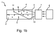
図1bは、図1aに示される照明デバイス1を、図1aにおける視野とは異なる側面から概略的に示し、発光要素は参照符号6によって示され、光角度選択モジュールは参照符号7によって示されている。 FIG. 1b schematically shows the lighting device 1 shown in FIG. 1a from a different side than the field of view in FIG. 1a, the light-emitting element is indicated by reference numeral 6 and the light angle selection module is indicated by reference numeral 7. Yes.
発光要素6、6a、6b、6cは、基本的に、光を生成し放射できる任意の種類の要素であってよい。例えば発光要素6、6a、6b、6cは、発光ダイオード(LED)を含む。照明デバイス1からダイナミックな色光出力を可能とするために、RGBのLEDを使用することが有利である。本発明に係る照明デバイス1内の複数の、即ち、2つ以上の発光要素6、6a、6b、6cは、同じタイプであっても異なるタイプであってもよい。
The
図1a及び図1bでは、ライトガイド2は、光入力面3を通り又はそれを介して入力光10を受け取り、光出力面4を通り又はそれを介して光を出力する導波管を含む。図1a及び図1bに示されるように、好適な実施形態では、ライトガイド2は、実質的にプレート状であり、その端に沿った端面と、上面及び底面とを有する。上面と底面とは平行である。光入力面3は、端面のうちの少なくとも1つの端面上に配置され、上面及び底面と直角をなす。光出力面4は、上面及び底面に配置される。代替的に、ライトガイド2は、様々な他の態様で構成されてもよい。例えばライトガイド2は、湾曲した上面及び底面を有する湾曲構造を有しても、よりロッド状の形状を有しても、三角形であっても、円形であっても、任意の他の規則的若しくは不規則な形状を有してもよい。代替案では、光出力面4は、上面又は底面上に配置される。
In FIGS. 1 a and 1 b, the
ライトガイド2は、ライトガイド内へと入力された光の伝播を、全反射(TIR)によって可能にする。ライトガイドは、光がその中を伝播可能な材料を含む。材料は透明材料であることが好適である。この材料の例としては、ポリ(メチルメタクリレート)(PMMA)、ポリカーボネート、ガラス及びシリコンゴムといった透明アクリル材料が挙げられる。
The
光散乱及び/又は反射粒子5が、導波管内に埋め込まれる。これらの粒子5は、出力光11として光の出力を可能にする。光散乱及び/又は反射粒子5は、当該粒子に衝突する光ビームの方向を転換し、また、光ビームの少なくとも一部の方向を、TIRの臨界角よりも小さい入射角で、光出力面4に向けて転換し、これにより、光ビームはライトガイド2の光出力面4から出力される。
Light scattering and / or
光角度選択モジュール7a、7b、7cは、発光要素6a、6b、6cによって放射された光を受け取る。光角度選択モジュールは更に、出力光の少なくとも一部が、ライトガイド2の光入力面3内へと入力されるように、光を出力する。
The light
光角度選択モジュール7a、7b、7cは更に、入射角の特定の区間内にある光線のみがライトガイド2内へと入力されるように、発光要素6a、6b、6cから放射された光の光線を選択又は適応させる。
The light
様々な入力光ビーム10a、10b、10cの入射角区間の変動は、光がライトガイド2から出力される方法の調節を可能にする。この原理は、図2に概略的に示される。図2は、光源6a、6bから生じる2つの例示的な光線110a、110bを示す。光入力面3は実質的に平らであるので、光入力面の各点における面法線は、ほぼ同じである。光入力面3の面法線の一例は、点線として示される。光線110aは、面法線に関して小角度αaで、即ち、小さい入射角で、ライトガイド2内へと入力される。光線110bは、より大きい入射角αbで、ライトガイド2内へと入力される。光線110a及び110bは、ライトガイド2内を、全反射(TIR)によって、移動する。図2に示されるシナリオでは、両方の光線110a、110bが、ライトガイド2内で移動した総距離は、実質的に同じである。しかし、光線110aは、光線110bよりもライトガイド2のより奥まで伝播している。光線110bは、光線110aの入射角αaよりも大きい入射角αbを有し、ライトガイド2内でより多くの反射が生じ、したがって、光線110aほどにはライトガイド2内の奥まで伝播しないが、図2に示されるこのシナリオにおける光線110a及び110bは、ライトガイド2内で実質的に同じ距離を移動する。
Variations in the angle of incidence of the various
ライトガイド2から出力される光の量は、ライトガイド2内の移動及び伝播の距離の関数である。したがって、大きい入射角αbを有する光線110bは、小さい入射角αaを有する光線110aよりも速くライトガイド2から出力される。小さい入射角αaを有する光線110aは、より遅く出力されるので、出力される前に、ライトガイド2のより奥まで伝播することができる。したがって、大きい入射角αを有する光線の割合が高い光ビームは、小さい入射角αを有する光線の割合が高い光ビームよりも速くライトガイド2から出力される。
The amount of light output from the
光ビームの入射角区間を調節する1つの方法は、コリメーションの使用によるものである。図1aでは、発光要素6aから放射される入力光ビーム10aは、発光要素6cから放射される入力光ビーム10cよりも高い度合にコリメートされている。光がコリメートされるほど、小さい入射角αを有する光線の割合が大きくなる。したがって、よりコリメートされた光が、あまりコリメートされない光よりも、より高い度合で、ライトガイド内の奥まで伝播する。図1aに例示されるように、発光要素6aから放射された光ビーム10aは、したがって、発光要素6cから放射された入力光ビーム10cよりも、ライトガイド2内の奥まで伝播する。入力光10aは更に、入力光10bよりもゆっくりと、したがって、あまり強くなく、ライトガイド2から出力される。これを補正するために、よりコリメートされた光ビーム10aの強度が増加される。光のコリメーションは、ライトガイドの光入力端において明るい光の点が登場するリスクを少なくして、入力光ビーム10の強度を増加させることを可能にする。
One way to adjust the angle of incidence of the light beam is through the use of collimation. In FIG. 1a, the
入力光ビーム10のコリメーションを変化させることによって、光がライトガイド2内を、光入力面3から、出力されるまで移動する距離を調節することができる。つまり、コリメーションの度合いは、光がライトガイドプレート2内を伝播する距離を変化させるために使用される。光はコリメートされるほど、ライトガイド2内をより奥まで移動し、光出力面4からよりゆっくりと出力される。つまり、光はコリメートされるほど、ライトガイド2内をより奥まで移動し、光出力効率は低下する。これは、例えば、光入力面3からの光の移動又は伝播距離が様々である形状を有するライトガイド2から均一な照明出力を達成するために使用される。図1aは、三角形であるライトガイド2を有する上記したような照明デバイス1を示す。図1aにおいて、ライトガイド2の実質的に全長に亘って出力されるために、光がライトガイド2内を移動しなければならない、L1によって概略的に示される距離は、三角形の底辺における発光要素6aから放射される入力光ビーム10aの方が、それぞれ、三角形の中間及び上部において発光要素6b及び6cから放射される入力光ビーム10b及び10cよりも長い。入力光ビーム10aが最もコリメートされるように、入力光ビーム10bがあまりコリメートされないように、入力光ビーム10cが最もコリメートされないようにすることによって、三角形の最も長い辺(L1によって示される)における光は、三角形の中間(L2によって示される)及び上部(L3によって示される)における光よりも、ライトガイド2内の奥まで移動する。光は、コリメーションによって、長い底辺を含む三角形の3つ全ての位置において、長さLに亘って均一に出力される。これにより、均一な出力光11が達成される。よりコリメートされた光の光出力の度合いの低さは、対応する大きさによって、よりコリメートされた入力光ビーム10の強度を増加させることによって、相殺される。したがって、更に、入力光ビーム10aが最も強くなるように、入力光ビーム10bがあまり強くないように、入力光ビーム10cが最も強くないようにすることによって、出力光11は、より一層、均一となる。
By changing the collimation of the
当業者は、三角形、又は、そうでなければ不規則な形状のライトガイド2の均一な出力照明は、以下に開示される光ブロックユニット8といった別のタイプの光選択モジュール8を使用することによっても、対応して構成されることを認識する。
Those skilled in the art will recognize that the uniform output illumination of the
図3aは、2つの発光要素6a、6bとライトガイド2とを含む本発明に係る照明デバイス1の概略的な実施形態を示す。ライトガイド2は、光散乱及び/又は反射粒子5を含み、発光要素6a、6bから、光入力面3を通して又はそれを介して、入力光10を受け取る。照明デバイス1は更に、対応する発光要素6a、6bからの光ビーム10a、10bを、当該光がライトガイド2内へと光入力面3を介して入力される前にコリメートする2つのコリメータ7a、7bを含む。コリメータ7a、7bは、発光要素6a、6bからの光を、当該光が光入力面3の面法線とより平行になるように、即ち、当該光が、光入力面3の面法線に実質的に直交する方向によりコリメートされるように、反射する。これにより、これらの光線の平均入射角αは減少される。コリメータ7aは、光の方向を、面法線に向けてより大きい度合で転換することによって、コリメータ7bよりも高い度合で光をコリメートする。
FIG. 3 a shows a schematic embodiment of a lighting device 1 according to the invention comprising two light emitting
図3bは、同様の実施形態を示すが、発光要素6a、6bから放射される光の異なるコリメーションを提供するために、単一のコリメータ7が使用される。単一のコリメータ7は、2つの発光要素6a、6bからの入力光ビーム10a、10bの方向を、方向転換角度の滑らかな推移を介して、異なるように転換する。これによって、発光要素6bによって放射された入力光ビーム10bから発光要素6aによって放射された入力光ビーム10aまで行く際に、コリメーションの度合いにおける滑らかな推移が達成される。
FIG. 3b shows a similar embodiment, but a single collimator 7 is used to provide different collimation of the light emitted from the
当然ながら、本発明に係る照明デバイス1には、図3a及び図3bに示されるよりも、より大きい数の発光要素6及び/又はコリメータ7が使用されてもよい。更に、当然ながら、コリメーションの度合いは、ライトガイド2の光入力面3に沿って徐々に増加又は減少される必要はない。ライトガイド2が不規則な形状を有する場合、又は、ライトガイド2に沿って異なる光出力を所望される別の理由がある場合、様々な度合いのコリメーションを提供する1つ以上のコリメータ7が、適宜、ライトガイド2に沿って配置されてよい。この点は、様々な度合いのコリメーションが、反射器、屈折器、光学ブロック、又は、フレネルレンズといった回折方法といったコリメータ以外の他のコリメーション調節要素によって達成される実施形態についても言えることである。
Of course, a larger number of light emitting elements 6 and / or collimators 7 may be used in the lighting device 1 according to the invention than shown in FIGS. 3a and 3b. Furthermore, it will be appreciated that the degree of collimation need not be gradually increased or decreased along the
様々な発光要素6からの入力光ビーム10の入射角区間の変動は、代替実施形態では、特定の入射角αにおいて移動する光が、例えば光学ブロックといった光ブロッカを使用することによって、ライトガイド内へと入力されることを阻止することによって達成される。図4は、光ブロックユニット8の形の光角度選択モジュールが、発光要素6の前に配置されている一例を示す。光ブロックユニット8は、小さい入射角αの区間内の光線が、ライトガイド内へと入力されることを阻止する。大きい入射角αを有する光線のみが、光ブロックユニット8を通過し、したがって、ライトガイド2内へと入力されることが可能である。結果として得られる入力光ビーム10は、大きい入射角αを有する光線の割合が大きいので、ライトガイド2内で短い距離を伝播する。したがって、このような光ブロックユニット8は、ライトガイド2内の奥まで伝播しないことが望まれる光について、低い度合のコリメーションを有する光を提供するのに適している。
Variations in the incident angle interval of the
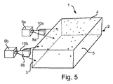
2つ以上の発光要素6から放射される光の入射角の様々な区間を達成するために、1つの光ブロックユニット8が、発光要素6のうちの一方の(他方ではない)発光要素からの光が遮断されるように使用される。或いは、図5に示されるように、2つ以上の光ブロックユニット8、即ち、各発光要素に対し1つの光ブロックユニットが使用されてもよい。この場合、光学ブロック8は、各光ブロックユニット8が、例えば異なるサイズであることによって、入射角αの区間が異なる光線が遮断されるように構成される。別の実施形態では、単一の光ブロックユニット8が、様々な発光要素6からの光を異なるように遮断するように使用される。このような単一の光ブロックユニット8は、例えば大きい入射角の区間の光線が光ブロックユニット8の第1の端において遮断され、小さい入射角の区間の光線が光ブロックユニット8の第2の端において遮断されるように、滑らかなサイズ推移を有することによって、推移する遮断の度合いを提供する。 In order to achieve various sections of the incident angle of light emitted from two or more light emitting elements 6, one light block unit 8 is provided from one (not the other) of the light emitting elements 6. Used so that light is blocked. Alternatively, as shown in FIG. 5, two or more light block units 8, i.e. one light block unit for each light emitting element, may be used. In this case, the optical block 8 is configured so that light beams having different sections of the incident angle α are blocked by the light block units 8 having different sizes, for example. In another embodiment, a single light block unit 8 is used to block light from various light emitting elements 6 differently. In such a single light block unit 8, for example, light rays in a section with a large incident angle are blocked at the first end of the light block unit 8, and light beams in a section with a small incident angle are second in the light block unit 8. Having a smooth size transition so that it is interrupted at the edges provides a degree of transition interruption.
結論として、光散乱及び/又は反射粒子が埋め込まれたライトガイドと、第1の発光要素と、第2の発光要素とを含む照明デバイスが開示される。照明デバイスは、第1の発光要素によって放射される光線については、ライトガイド内へと入力される当該光線の入射角が、第1の角度区間内であり、第2の発光要素によって放射される光線については、ライトガイド内へと入力される当該光線の入射角が、第2の角度区間内であるように構成され、第1の角度区間と第2の角度区間とは異なる。選択された位置においてライトガイドから出力される光の量が、例えば均一な照明を与えるために、所望通りに適応される照明デバイスが提供される。 In conclusion, an illumination device is disclosed that includes a light guide embedded with light scattering and / or reflective particles, a first light emitting element, and a second light emitting element. For the light emitted by the first light emitting element, the lighting device has the incident angle of the light input into the light guide within the first angular interval and is emitted by the second light emitting element. Regarding the light beam, the incident angle of the light beam input into the light guide is configured to be within the second angle section, and the first angle section and the second angle section are different. An illumination device is provided in which the amount of light output from the light guide at the selected location is adapted as desired, for example to provide uniform illumination.
本発明は、添付図面及び上記説明において詳細に例示かつ説明されたが、当該例示及び説明は、例示的であって限定的に解釈されるべきではない。本発明は、開示された実施形態に限定されない。開示された実施形態に対する他の変形態様も、図面、開示内容及び添付の請求項を検討することにより、請求項に係る発明を実施する当業者には理解されかつ実施可能である。特定の手段が相互に異なる従属請求項に記載されるからといって、これらの手段の組み合わせを有利に使用することができないことを示すものではない。請求項における任意の参照符号は、範囲を限定しているものと解釈されるべきではない。 Although the invention has been illustrated and described in detail in the accompanying drawings and the foregoing description, the illustration and description are exemplary and should not be construed as limiting. The invention is not limited to the disclosed embodiments. Other variations to the disclosed embodiments can be understood and implemented by those skilled in the art of practicing the claimed invention after reviewing the drawings, the disclosure, and the appended claims. The mere fact that certain measures are recited in mutually different dependent claims does not indicate that a combination of these measured cannot be used to advantage. Any reference signs in the claims should not be construed as limiting the scope.
Claims (14)
第1の発光要素と、
第2の発光要素と、
を含む照明デバイスであって、
前記第1の発光要素及び前記第2の発光要素によってそれぞれ放射される光の少なくとも一部が、前記光入力面に衝突し、
前記照明デバイスは、前記第1の発光要素によって放射される光線について、前記光入力面に衝突する光線の入射角が、第1の角度区間内にあるように構成され、
前記照明デバイスは、前記第2の発光要素によって放射される光線について、前記光入力面に衝突する光線の入射角が、第2の角度区間内にあるように構成され、
前記第1の角度区間と前記第2の角度区間とは異なる、照明デバイス。 The light guide comprising embedded light scattering and / or light reflecting particles and the light input surface for inputting light impinging on the light input surface into the light guide;
A first light emitting element;
A second light emitting element;
A lighting device comprising:
At least some of the light emitted by each of the first light emitting element and the second light emitting element impinges on the light input surface;
The lighting device is configured such that, for a light beam emitted by the first light emitting element, an incident angle of the light beam that collides with the light input surface is within a first angle section;
The lighting device is configured such that, for a light beam emitted by the second light emitting element, an incident angle of the light beam colliding with the light input surface is within a second angle section;
The lighting device, wherein the first angle section and the second angle section are different.
前記光角度選択モジュールは、前記第1の発光要素によって放射される光線について、前記光入力面に衝突する光線の入射角が、前記第1の角度区間内にあるように構成され、
前記光角度選択モジュールは、前記第2の発光要素によって放射される光線について、前記光入力面に衝突する光線の入射角が、前記第2の角度区間内にあるように構成される、請求項1に記載の照明デバイス。 Receiving light emitted by the first light emitting element and the second light emitting element, respectively, and at least a part of the light emitted by the first light emitting element and the second light emitting element respectively is the light input surface. A light angle selection module for outputting light so as to collide with
The light angle selection module is configured such that, for a light beam emitted by the first light emitting element, an incident angle of the light beam colliding with the light input surface is within the first angle section,
The light angle selection module is configured such that, for a light beam emitted by the second light emitting element, an incident angle of a light beam that collides with the light input surface is within the second angle section. The lighting device according to 1.
前記光角度選択モジュールは、前記第2の発光要素によって放射される光線について、前記平面に対して前記光入力面に衝突する光線の入射角が、第2の角度区間内にあるように構成され、
前記平面は、前記光入力面の面法線及び前記光入力面の前記面法線に直交する方向のうちの少なくとも1つによって画定される、請求項2に記載の照明デバイス。 The light angle selection module is configured such that, for a light beam emitted by the first light emitting element, an incident angle of a light beam that collides with the light input surface with respect to a plane is within a first angle section;
The light angle selection module is configured such that an incident angle of a light beam colliding with the light input surface with respect to the plane is within a second angle section with respect to the light beam emitted by the second light emitting element. ,
The lighting device according to claim 2, wherein the plane is defined by at least one of a surface normal of the light input surface and a direction orthogonal to the surface normal of the light input surface.
Applications Claiming Priority (3)
| Application Number | Priority Date | Filing Date | Title |
|---|---|---|---|
| US201261695809P | 2012-08-31 | 2012-08-31 | |
| US61/695,809 | 2012-08-31 | ||
| PCT/IB2013/056833 WO2014033602A2 (en) | 2012-08-31 | 2013-08-23 | Illumination device based on light guide with light scattering particles and light angle selection module |
Publications (2)
| Publication Number | Publication Date |
|---|---|
| JP2015528634A true JP2015528634A (en) | 2015-09-28 |
| JP2015528634A5 JP2015528634A5 (en) | 2016-10-13 |
Family
ID=49622849
Family Applications (1)
| Application Number | Title | Priority Date | Filing Date |
|---|---|---|---|
| JP2015529164A Pending JP2015528634A (en) | 2012-08-31 | 2013-08-23 | Lighting device based on light guide with light scattering particles and light angle selection module |
Country Status (6)
| Country | Link |
|---|---|
| US (1) | US20150205031A1 (en) |
| EP (1) | EP2890928A2 (en) |
| JP (1) | JP2015528634A (en) |
| CN (1) | CN104583672A (en) |
| RU (1) | RU2638822C2 (en) |
| WO (1) | WO2014033602A2 (en) |
Cited By (1)
| Publication number | Priority date | Publication date | Assignee | Title |
|---|---|---|---|---|
| KR20190086313A (en) * | 2018-01-12 | 2019-07-22 | 엘지전자 주식회사 | Lamp for vehicle and vehicle |
Families Citing this family (2)
| Publication number | Priority date | Publication date | Assignee | Title |
|---|---|---|---|---|
| EP4043944A1 (en) * | 2016-01-12 | 2022-08-17 | Magic Leap, Inc. | Beam angle sensor in virtual/augmented reality system |
| US10955607B2 (en) * | 2017-03-07 | 2021-03-23 | Lumileds Llc | LED lighting device with remote phosphor in-coupling structure for in-coupling light from light emitting diodes |
Citations (5)
| Publication number | Priority date | Publication date | Assignee | Title |
|---|---|---|---|---|
| JP2007108438A (en) * | 2005-10-13 | 2007-04-26 | Harison Toshiba Lighting Corp | Illuminating device |
| US20090147533A1 (en) * | 2007-12-06 | 2009-06-11 | Kee Tae Um | Display Device |
| JP2011060685A (en) * | 2009-09-14 | 2011-03-24 | Panasonic Corp | Light source unit |
| US20110085332A1 (en) * | 2008-05-30 | 2011-04-14 | Koninklijke Philips Electronics N.V. | Illumination device comprising a collimator |
| US20110096570A1 (en) * | 2008-05-30 | 2011-04-28 | Koninklijke Philips Electronics N.V. | Illumination device comprising a light guide |
Family Cites Families (14)
| Publication number | Priority date | Publication date | Assignee | Title |
|---|---|---|---|---|
| IL148804A (en) * | 2002-03-21 | 2007-02-11 | Yaacov Amitai | Optical device |
| JP3551187B2 (en) * | 2002-11-28 | 2004-08-04 | セイコーエプソン株式会社 | Optical element, illumination device, and projection display device |
| IL157837A (en) * | 2003-09-10 | 2012-12-31 | Yaakov Amitai | Substrate-guided optical device particularly for three-dimensional displays |
| WO2006129220A1 (en) * | 2005-05-30 | 2006-12-07 | Koninklijke Philips Electronics N.V. | Light-emitting device with brightness enhancing layer |
| EP1954976A1 (en) * | 2005-11-21 | 2008-08-13 | Koninklijke Philips Electronics N.V. | Lighting device |
| EP1978300B1 (en) * | 2006-01-23 | 2014-03-19 | FUJIFILM Corporation | Planar illumination device |
| JP4626645B2 (en) * | 2007-11-27 | 2011-02-09 | ソニー株式会社 | Display device and optical device |
| US8434913B2 (en) | 2008-05-30 | 2013-05-07 | Koninklijke Philips Electronics N.V. | Round illumination device |
| RU2431168C2 (en) * | 2008-07-11 | 2011-10-10 | Корпорация "САМСУНГ ЭЛЕКТРОНИКС Ко., Лтд." | Illumination device |
| WO2010049912A2 (en) * | 2008-10-31 | 2010-05-06 | Udayan Kanade | A light source with light recovery mechanism |
| KR101621013B1 (en) * | 2008-12-09 | 2016-05-16 | 삼성디스플레이 주식회사 | Display device |
| KR20120045098A (en) * | 2010-10-29 | 2012-05-09 | 삼성전자주식회사 | Backlight assembly and liquid crystal device having the same |
| TWI428673B (en) * | 2010-11-15 | 2014-03-01 | Young Lighting Technology Corp | Blacklight module |
| KR20120088121A (en) * | 2011-01-31 | 2012-08-08 | 삼성전자주식회사 | Backlight assembly and display apparatus having the same |
-
2013
- 2013-08-23 US US14/423,341 patent/US20150205031A1/en not_active Abandoned
- 2013-08-23 EP EP13792976.6A patent/EP2890928A2/en not_active Withdrawn
- 2013-08-23 CN CN201380044980.9A patent/CN104583672A/en active Pending
- 2013-08-23 WO PCT/IB2013/056833 patent/WO2014033602A2/en active Application Filing
- 2013-08-23 RU RU2015111537A patent/RU2638822C2/en not_active IP Right Cessation
- 2013-08-23 JP JP2015529164A patent/JP2015528634A/en active Pending
Patent Citations (5)
| Publication number | Priority date | Publication date | Assignee | Title |
|---|---|---|---|---|
| JP2007108438A (en) * | 2005-10-13 | 2007-04-26 | Harison Toshiba Lighting Corp | Illuminating device |
| US20090147533A1 (en) * | 2007-12-06 | 2009-06-11 | Kee Tae Um | Display Device |
| US20110085332A1 (en) * | 2008-05-30 | 2011-04-14 | Koninklijke Philips Electronics N.V. | Illumination device comprising a collimator |
| US20110096570A1 (en) * | 2008-05-30 | 2011-04-28 | Koninklijke Philips Electronics N.V. | Illumination device comprising a light guide |
| JP2011060685A (en) * | 2009-09-14 | 2011-03-24 | Panasonic Corp | Light source unit |
Cited By (3)
| Publication number | Priority date | Publication date | Assignee | Title |
|---|---|---|---|---|
| KR20190086313A (en) * | 2018-01-12 | 2019-07-22 | 엘지전자 주식회사 | Lamp for vehicle and vehicle |
| KR102116173B1 (en) * | 2018-01-12 | 2020-05-28 | 제트카베 그룹 게엠베하 | Lamp for vehicle and vehicle |
| US10731815B2 (en) | 2018-01-12 | 2020-08-04 | Zkw Group Gmbh | Lamp for vehicle and vehicle |
Also Published As
| Publication number | Publication date |
|---|---|
| CN104583672A (en) | 2015-04-29 |
| RU2015111537A (en) | 2016-10-20 |
| WO2014033602A2 (en) | 2014-03-06 |
| RU2638822C2 (en) | 2017-12-18 |
| US20150205031A1 (en) | 2015-07-23 |
| EP2890928A2 (en) | 2015-07-08 |
| WO2014033602A3 (en) | 2014-05-30 |
Similar Documents
| Publication | Publication Date | Title |
|---|---|---|
| JP5530426B2 (en) | Illumination device having a collimator | |
| JP5779096B2 (en) | Lighting system, lighting fixture, collimator, and display device | |
| US9121982B2 (en) | Light-emitting device for emitting diffuse light | |
| WO2010058554A1 (en) | Optical element and light-emitting device | |
| KR20120052289A (en) | Free form lighting module | |
| WO2010044190A1 (en) | Optical element and light emitting device | |
| US8287172B2 (en) | Planar illumination device | |
| JP2004158452A (en) | Backlight unit | |
| JP2010224089A (en) | Prism | |
| KR20120066658A (en) | Light-emitting device | |
| KR102244847B1 (en) | Super Directional Light Guide Film And Thin Film Type Back Light Unit For Flat Panel Display Using The Same | |
| JP7083830B2 (en) | Light emitting module with light guide plate for automobile headlights | |
| JP2014103063A (en) | Lighting system | |
| CN102803836A (en) | Illumination apparatus | |
| JP2015528634A (en) | Lighting device based on light guide with light scattering particles and light angle selection module | |
| JP2011138774A (en) | Light guide plate and backlight module using the same | |
| WO2014033576A1 (en) | Illumination device based on light guide with light diffusing particles | |
| TWI655463B (en) | Lighting device | |
| JP2005539356A (en) | Light emitting device having light input and light output unit | |
| CN104482501B (en) | Optical element, optical module and lighting device | |
| CN202532218U (en) | Lamp structure with batwing-shaped light intensity distribution | |
| WO2019080634A1 (en) | Led total reflection lens, led light guide body, and automobile lamp | |
| CN109477627B (en) | Lighting system using light guiding structure | |
| JP6285220B2 (en) | LIGHTING DEVICE AND LIGHTING APPARATUS HAVING THE SAME | |
| JP2004139901A (en) | Lighting device |
Legal Events
| Date | Code | Title | Description |
|---|---|---|---|
| A521 | Request for written amendment filed |
Free format text: JAPANESE INTERMEDIATE CODE: A523 Effective date: 20160819 |
|
| A621 | Written request for application examination |
Free format text: JAPANESE INTERMEDIATE CODE: A621 Effective date: 20160819 |
|
| A711 | Notification of change in applicant |
Free format text: JAPANESE INTERMEDIATE CODE: A711 Effective date: 20160912 |
|
| A977 | Report on retrieval |
Free format text: JAPANESE INTERMEDIATE CODE: A971007 Effective date: 20170714 |
|
| A131 | Notification of reasons for refusal |
Free format text: JAPANESE INTERMEDIATE CODE: A131 Effective date: 20170724 |
|
| A601 | Written request for extension of time |
Free format text: JAPANESE INTERMEDIATE CODE: A601 Effective date: 20171020 |
|
| A02 | Decision of refusal |
Free format text: JAPANESE INTERMEDIATE CODE: A02 Effective date: 20180410 |